

Page 1

XJ PASSIVE RESTRAINT SYSTEMS 8M - 1
PASSIVE RESTRAINT SYSTEMS
TABLE OF CONTENTS
page page
DESCRIPTION AND OPERATION
AIRBAG SYSTEM .........................1
DRIVER SIDE AIRBAG MODULE .............2
PASSENGER SIDE AIRBAG MODULE..........3
AIRBAG CONTROL MODULE ................3
CLOCKSPRING ...........................4
DIAGNOSIS AND TESTING
AIRBAG SYSTEM .........................4
SERVICE PROCEDURES
AIRBAG SYSTEM .........................5
REMOVAL AND INSTALLATION
DRIVER SIDE AIRBAG MODULE .............6
DESCRIPTION AND OPERATION
AIRBAG SYSTEM
DESCRIPTION
A dual front airbag system is standard factory-installed safety equipment on this model. The primary
passenger restraints in this vehicle are the standard
equipment factory-installed seat belts, which require
active use by the vehicle occupants. The airbag system is a supplemental passive restraint that was
designed and is intended to enhance the protection
for the front seat occupants of the vehicle only when
used in conjunction with the seat belts. See the owner’s manual in the vehicle glove box for more information on the features, use and operation of all of
the factory-installed passenger restraints, including
the airbag system.
NOTE: This group covers both Left-Hand Drive
(LHD) and Right-Hand Drive (RHD) versions of this
model. Whenever required and feasible, the RHD
versions of affected vehicle components have been
constructed as mirror-image of the LHD versions.
While most of the illustrations used in this group
represent only the LHD version, the diagnostic and
service procedures outlined can generally be
applied to either version. Exceptions to this rule
have been clearly identified as LHD or RHD, if a
special illustration or procedure is required.
The dual front airbag system consists of the following components:
• Airbag Control Module (ACM)
DRIVER SIDE AIRBAG MODULE TRIM
COVER................................7
PASSENGER SIDE AIRBAG MODULE..........9
PASSENGER SIDE AIRBAG DOOR...........11
AIRBAG CONTROL MODULE ...............12
CLOCKSPRING ..........................13
ADJUSTMENTS
CLOCKSPRING CENTERING................15
SPECIAL TOOLS
PASSIVE RESTRAINT SYSTEMS ............16
• Airbag indicator lamp
• Clockspring
• Driver and passenger side airbag modules
(including the airbag inflators)
• Driver and passenger side knee blockers
• Wire harness and connections.
This group provides complete service information
for the ACM, both airbag modules, and the clockspring. Complete service information for the other
airbag system components can be located as follows:
• Refer to Instrument Cluster in the proper sec-
tion of Group 8E - Instrument Panel Systems for
complete service information for the airbag indicator
lamp.
• Refer to Knee Blocker in the Removal and
Installation section of Group 8E - Instrument Panel
Systems for complete service information on the
driver side knee blocker.
• Refer to Glove Box in the Removal and Instal-
lation section of Group 8E - Instrument Panel Systems for complete service information on the
passenger side knee blocker.
• Refer to Airbag System in the Contents of
Group 8W - Wiring Diagrams for complete service
information and circuit diagrams for the airbag system wiring components.
See the proper Diagnostic Procedures manual to
test or diagnose a problem with any component of
the airbag system.
OPERATION
The airbag system electrical circuits are continuously monitored and controlled by a microprocessor
and software contained within the Airbag Control
Page 2

8M - 2 PASSIVE RESTRAINT SYSTEMS XJ
DESCRIPTION AND OPERATION (Continued)
Module (ACM). The ACM also contains an impact
sensor and a safing sensor, which are monitored by
the ACM to determine when an impact occurs that is
severe enough to require airbag system protection.
When a frontal impact is severe enough, the ACM
signals the inflator units of both airbag modules to
deploy the airbags.
An airbag indicator lamp in the instrument cluster
lights for about seven seconds as a bulb test, each
time the ignition switch is turned to the On or Start
positions. Following the bulb test, the airbag indicator lamp is turned on or off by the ACM to indicate
the status of the airbag system. If the airbag indicator lamp comes on at any time other than during the
bulb test, it indicates that there is a problem in the
airbag system circuits. Such a problem may cause
the airbags not to deploy when required, or to deploy
when not required.
The driver side airbag module includes an inflatable airbag and an inflator unit behind a trim cover
in the hub area of the steering wheel. The passenger
side airbag module includes a second inflatable airbag and an inflator unit behind an airbag door in the
instrument panel above the glove box.
During a frontal vehicle impact, the knee blockers
work in concert with properly adjusted seat belts to
restrain the driver and front seat passenger in the
proper position for an airbag deployment. The knee
blockers also work to absorb and distribute the crash
energy from the driver and front seat passenger to
the structure of the instrument panel. The driver
side knee blocker is a stamped metal reinforcement
located behind the instrument panel steering column
opening cover. The passenger side knee blocker is
integral to the glove box door.
Following are general descriptions of the major
components in the airbag system.
WARNING:
• THE AIRBAG SYSTEM IS A SENSITIVE, COMPLEX ELECTROMECHANICAL UNIT. BEFORE
ATTEMPTING TO DIAGNOSE OR SERVICE ANY AIRBAG SYSTEM OR RELATED STEERING WHEEL,
STEERING COLUMN, OR INSTRUMENT PANEL
COMPONENTS YOU MUST FIRST DISCONNECT
AND ISOLATE THE BATTERY NEGATIVE (GROUND)
CABLE. THEN WAIT TWO MINUTES FOR THE SYSTEM CAPACITOR TO DISCHARGE BEFORE FURTHER SYSTEM SERVICE. THIS IS THE ONLY SURE
WAY TO DISABLE THE AIRBAG SYSTEM. FAILURE
TO DO THIS COULD RESULT IN ACCIDENTAL AIRBAG DEPLOYMENT AND POSSIBLE PERSONAL
INJURY.
• THE DRIVER SIDE AIRBAG MODULE INFLATOR
ASSEMBLY CONTAINS SODIUM AZIDE AND POTASSIUM NITRATE. THESE MATERIALS ARE POISONOUS AND EXTREMELY FLAMMABLE. CONTACT
WITH ACID, WATER, OR HEAVY METALS MAY PRODUCE HARMFUL AND IRRITATING GASES (SODIUM
HYDROXIDE IS FORMED IN THE PRESENCE OF
MOISTURE) OR COMBUSTIBLE COMPOUNDS. THE
PASSENGER AIRBAG MODULE CONTAINS ARGON
GAS PRESSURIZED TO OVER 2500 PSI. DO NOT
ATTEMPT TO DISMANTLE AN AIRBAG MODULE OR
TAMPER WITH ITS INFLATOR. DO NOT PUNCTURE,
INCINERATE, OR BRING INTO CONTACT WITH
ELECTRICITY. DO NOT STORE AT TEMPERATURES
EXCEEDING 93° C (200° F).
• REPLACE AIRBAG SYSTEM COMPONENTS
ONLY WITH PARTS SPECIFIED IN THE CHRYSLER
MOPAR PARTS CATALOG. SUBSTITUTE PARTS
MAY APPEAR INTERCHANGEABLE, BUT INTERNAL
DIFFERENCES MAY RESULT IN INFERIOR OCCUPANT PROTECTION.
• THE FASTENERS, SCREWS, AND BOLTS ORIGINALLY USED FOR THE AIRBAG SYSTEM COMPONENTS HAVE SPECIAL COATINGS AND ARE
SPECIFICALLY DESIGNED FOR THE AIRBAG SYSTEM. THEY MUST NEVER BE REPLACED WITH ANY
SUBSTITUTES. ANY TIME A NEW FASTENER IS
NEEDED, REPLACE IT WITH THE CORRECT FASTENERS PROVIDED IN THE SERVICE PACKAGE OR
SPECIFIED IN THE CHRYSLER MOPAR PARTS CATALOG.
• WHEN A STEERING COLUMN HAS AN AIRBAG
MODULE ATTACHED, NEVER PLACE THE COLUMN
ON THE FLOOR OR ANY OTHER SURFACE WITH
THE STEERING WHEEL OR AIRBAG MODULE FACE
DOWN.
DRIVER SIDE AIRBAG MODULE
DESCRIPTION
The driver side airbag module protective trim cover
is the most visible part of the driver side airbag system. The driver side airbag module is mounted
directly to the steering wheel. Located under the airbag module trim cover are the horn switch, the
folded airbag cushion, and the airbag cushion supporting components. The resistive membrane-type
horn switch is secured with heat stakes to the inside
surface of the airbag module trim cover, between the
trim cover and the folded airbag cushion.
The driver side airbag module cannot be repaired,
and must be replaced if deployed or in any way damaged. The driver side airbag module trim cover and
the horn switch are available as a unit for service
replacement.
OPERATION
The driver side airbag module includes a stamped
metal housing to which the cushion and an inflator
Page 3

XJ PASSIVE RESTRAINT SYSTEMS 8M - 3
DESCRIPTION AND OPERATION (Continued)
unit are attached and sealed. The conventional pyrotechnic-type inflator assembly is mounted to studs on
the back of the airbag module housing. The inflator
seals the hole in the airbag cushion so it can discharge the gas it produces directly into the cushion
when supplied with the proper electrical signal. Following an airbag deployment, the airbag cushion
quickly deflates by venting this gas towards the
instrument panel through the porous fabric material
used on the steering wheel side of the airbag cushion.
The protective trim cover is fitted to the front of
the airbag module and forms a decorative cover in
the center of the steering wheel. The inside of the
trim cover has locking blocks molded into it that
engage a lip on the airbag module metal housing.
Two stamped metal retainers then fit over the inflator mounting studs on the back of the airbag module
housing and are engaged in slots on the inside of the
cover, securely locking the trim cover into place. The
trim cover will split at predetermined breakout lines,
then fold back out of the way along with the horn
switch upon airbag deployment.
PASSENGER SIDE AIRBAG MODULE
DESCRIPTION
The passenger side airbag door on the instrument
panel above the glove box is the most visible part of
the passenger side airbag system. Located under the
airbag door are the passenger side airbag cushion
and the airbag cushion supporting components.
The passenger side airbag module includes an
extruded aluminum housing within which the cushion and inflator are mounted and sealed. Two
stamped metal brackets, one on each end of the housing, enclose the cushion and inflator and also serve
as the mounting brackets for the module. The two
mounting brackets at the top front of the airbag module are secured with screws to the top of the instrument panel structural support beneath the
instrument panel top cover. The two mounting brackets at the bottom front of the airbag module are
secured with screws to the instrument panel structural support over the glove box.
Following a passenger side airbag deployment, the
passenger side airbag module and the passenger side
airbag door must be replaced. The passenger side airbag module cannot be repaired, and must be replaced
if deployed or in any way damaged. The passenger
side airbag door is available as a separate service
item.
OPERATION
The hybrid-type inflator assembly includes a small
canister of highly compressed argon gas. The inflator
seals the hole in the airbag cushion so it can dis-
charge the gas it produces directly into the cushion
when supplied with the proper electrical signal. Following an airbag deployment, the airbag cushion
quickly deflates by venting this gas through the
porous fabric material used on each end panel of the
airbag cushion.
The molded plastic passenger side airbag door is
secured to extruded tabs at the top and bottom rear
of the airbag module housing by keyed openings in
the upper and lower mounting flange returns of the
airbag door. The upper and lower airbag door mounting flanges are then secured to the instrument panel
structural support and the upper glove box opening
reinforcement with screws. The airbag door has predetermined breakout lines concealed beneath its decorative cover. Upon airbag deployment, the airbag
door will split at the breakout lines and the door will
fold back over the top of the instrument panel, out of
the way.
AIRBAG CONTROL MODULE
DESCRIPTION
The Airbag Control Module (ACM) is secured with
nuts to weld-studs on the ACM mounting bracket.
The ACM mounting bracket is secured with screws to
the floor panel transmission tunnel underneath the
center floor console and behind the park brake mechanism in the passenger compartment of the vehicle.
The ACM contains an electronic microprocessor, an
electronic impact sensor, an electromechanical safing
sensor, and an energy storage capacitor.
The ACM cannot be repaired or adjusted and, if
damaged or faulty, it must be replaced.
OPERATION
The microprocessor in the ACM contains the airbag
system logic. The airbag system logic includes
On-Board Diagnostics (OBD), and the ability to communicate with the instrument cluster circuitry over
the Chrysler Collision Detection (CCD) data bus to
control the airbag indicator lamp. The microprocessor
continuously monitors all of the airbag system electrical circuits to determine the system readiness. If
the ACM detects a monitored system fault, it sends
messages to the instrument cluster over the CCD
data bus to turn on the airbag indicator lamp. Refer
to Instrument Cluster in the proper section of
Group 8E - Instrument Panel Systems for more information on the airbag indicator lamp.
One electronic impact sensor is used in this airbag
system. The impact sensor is an accelerometer that
senses the rate of vehicle deceleration, which provides verification of the direction and severity of an
impact. The impact sensor is calibrated for the specific vehicle, and is only serviced as a unit with the
Page 4
8M - 4 PASSIVE RESTRAINT SYSTEMS XJ
DESCRIPTION AND OPERATION (Continued)
ACM. A pre-programmed decision algorithm in the
ACM microprocessor determines when the deceleration rate as signaled by the impact sensor indicates
an impact that is severe enough to require airbag
system protection. When the programmed conditions
are met, the ACM sends an electrical signal to deploy
the airbags.
In addition to the electronic impact sensor, there is
an electromechanical sensor within the ACM called a
safing sensor. The safing sensor is a normally open
series switch located in the airbag deployment circuit
of the ACM. This sensor detects impact energy of a
lesser magnitude than the electronic impact sensor,
and must be closed in order for the airbags to deploy.
The ACM also contains an energy-storage capacitor. This capacitor stores enough electrical energy to
deploy the airbags for up to one second following a
battery disconnect or failure during an impact. The
purpose of the capacitor is to provide airbag system
protection in a severe secondary impact, if the initial
impact has damaged or disconnected the battery, but
was not severe enough to deploy the airbags.
CLOCKSPRING
DESCRIPTION
The clockspring assembly is secured with two integral plastic latches onto the steering column lock
housing near the top of the steering column behind
the steering wheel. The clockspring is used to maintain a continuous electrical circuit between the fixed
clockspring wire harness on the steering column and
several electrical components that rotate with the
steering wheel. The rotating components include the
driver side airbag module, the horn switch and, if the
vehicle is so equipped, the vehicle speed control
switches.
The clockspring cannot be repaired. If the clockspring is faulty, damaged, or if the driver side airbag
has been deployed, the clockspring must be replaced.
However, if the clockspring is removed for service or
if the steering column is disconnected from the steering gear allowing the clockspring tape to change position relative to the other steering components, it
must be re-centered following completion of the service or it may be damaged. Refer to Clockspring
Centering in the Adjustments section of this group
for the proper centering procedures.
Service replacement clocksprings are shipped precentered and with a locking pin installed. This locking pin should not be removed until the clockspring
has been installed on the steering column. If the
locking pin is removed before the clockspring is
installed on a steering column, the clockspring centering procedure must be performed.
DIAGNOSIS AND TESTING
AIRBAG SYSTEM
A DRB scan tool is required for diagnosis of the
airbag system. See the proper Diagnostic Procedures
manual for more information.
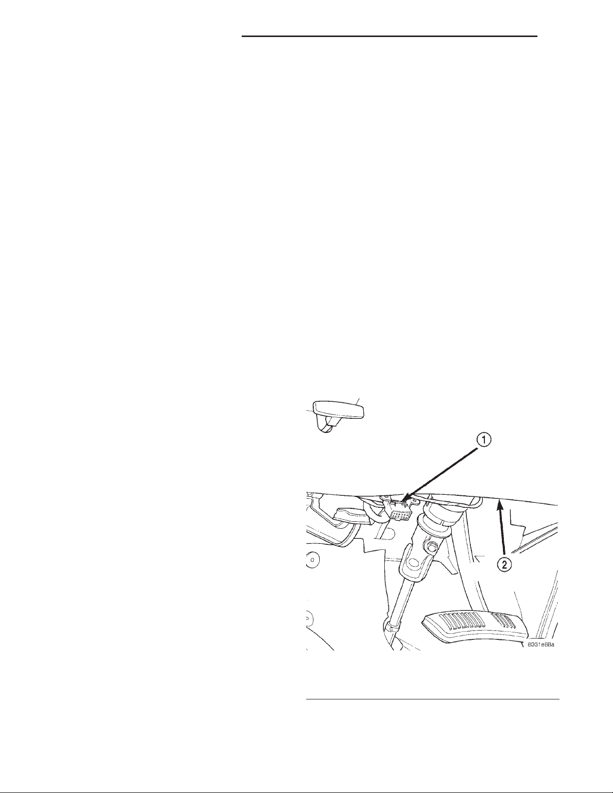
(1) Connect the DRB scan tool to the 16-way data
link wire harness connector. The connector is located
on the driver side lower edge of the instrument
panel, outboard of the steering column (Fig. 1).
OPERATION
The clockspring assembly consists of a plastic case
which contains a flat, ribbon-like, electrically conductive tape that winds and unwinds like a clockspring
with the steering wheel rotation. The electrically conductive tape consists of several fine gauge copper
wire leads sandwiched between two narrow strips of
plastic film.
Like the clockspring in a timepiece, the clockspring
tape has travel limits and can be damaged by being
wound too tightly. To prevent this from occurring, the
clockspring is centered when it is installed on the
steering column. Centering the clockspring indexes
the clockspring tape to other steering components so
that it can operate within its designed travel limits.
Fig. 1 16-Way Data Link Connector - Typical
1 – 16–WAY DATA LINK CONNECTOR
2 – BOTTOM OF INSTRUMENT PANEL
(2) Turn the ignition switch to the On position.
Exit the vehicle with the DRB. Be certain that the
Page 5

XJ PASSIVE RESTRAINT SYSTEMS 8M - 5
DIAGNOSIS AND TESTING (Continued)
DRB contains the latest version of the proper DRB
software.
(3) Using the DRB, read and record the active
Diagnostic Trouble Code (DTC) data.
(4) Read and record any stored DTC data.
(5) See the proper Diagnostic Procedures manual if
any DTC is found in Step 3 or Step 4.
(6) After completing the necessary repairs, try to
erase the stored DTC data. If any problems remain,
the stored DTC data will not erase. See the proper
Diagnostic Procedures manual for the procedures to
diagnose any stored DTC that will not erase.
(7) With the ignition switch still in the On position, check to be certain that nobody is in the vehicle.
(8) From outside of the vehicle (away from the airbags in case of an accidental deployment) turn the
ignition switch to the Off position for about ten seconds, and then back to the On position. Observe the
airbag indicator lamp in the instrument cluster. It
should light for six to eight seconds, and then go out.
This indicates that the airbag system is functioning
normally.
NOTE: If the airbag indicator lamp fails to light, or
lights and stays on, there is an airbag system malfunction. See the proper Diagnostic Procedures
manual to diagnose the problem.
SERVICE PROCEDURES
DISPOSAL OF NON-DEPLOYED AIRBAG MODULES
All damaged or faulty and non-deployed driver side
or passenger side airbag modules which are replaced
on vehicles are to be returned. If an airbag module
assembly is faulty or damaged and non-deployed,
refer to the parts return list in the current Chrysler
Corporation Warranty Policies and Procedures manual for the proper handling and disposal procedures.
DEPLOYED
Any vehicle which is to be returned to use after an
airbag deployment, must have both airbag modules,
the passenger side airbag module door and the clockspring replaced. These components will be damaged
or weakened as a result of an airbag deployment,
which may or may not be obvious during a visual
inspection, and are not intended for reuse.
Other vehicle components should be closely
inspected, but are to be replaced only as required by
the extent of the visible damage incurred.
STORAGE
An airbag module must be stored in its original,
special container until used for service. Also, it must
be stored in a clean, dry environment; away from
sources of extreme heat, sparks, and high electrical
energy. Always place or store an airbag module on a
surface with its trim cover or airbag side facing up,
to minimize movement in case of an accidental
deployment.
AIRBAG SYSTEM
NON-DEPLOYED
At no time should any source of electricity be permitted near the inflator on the back of an airbag
module. When carrying a non-deployed airbag module, the trim cover or airbag side of the module
should be pointed away from the body to minimize
injury in the event of an accidental deployment. If
the module is placed on a bench or any other surface,
the trim cover or airbag side of the module should be
face up to minimize movement in the event of an
accidental deployment.
In addition, the airbag system should be disarmed
whenever any steering wheel, steering column, or
instrument panel components require diagnosis or
service. Failure to observe this warning could result
in accidental airbag deployment and possible personal injury. Refer to Group 8E - Instrument
Panel Systems for additional service procedures on
the instrument panel components. Refer to Group
19 - Steering for additional service procedures on
the steering wheel and steering column components.
CLEANUP PROCEDURE
Following an airbag system deployment, the vehicle interior will contain a powdery residue. This residue consists primarily of harmless particulate
by-products of the small pyrotechnic charge used to
initiate the airbag deployment propellant. However,
this residue will also contain traces of sodium
hydroxide powder, a chemical by-product of the propellant material that is used to generate the nitrogen
gas that inflates the airbag. Since sodium hydroxide
powder can irritate the skin, eyes, nose, or throat, be
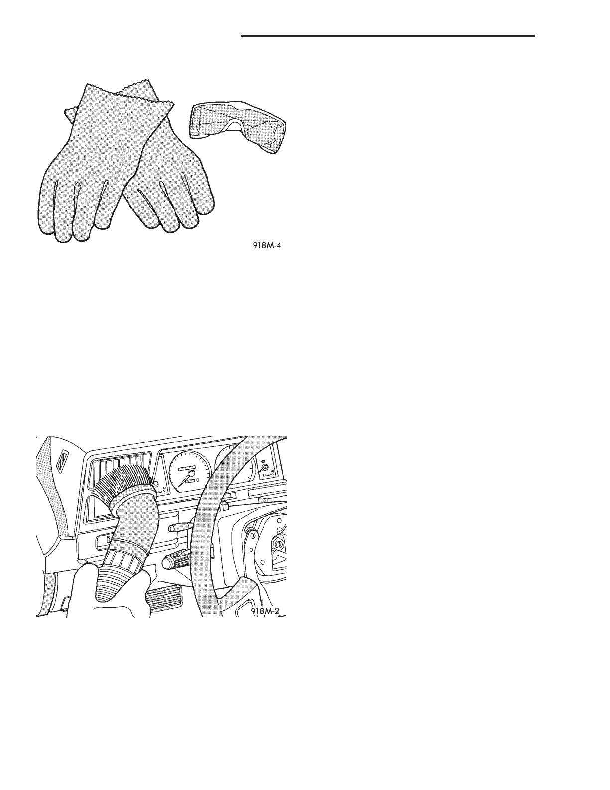
sure to wear safety glasses, rubber gloves, and a
long-sleeved shirt during cleanup (Fig. 2).
WARNING: IF YOU EXPERIENCE SKIN IRRITATION
DURING CLEANUP, RUN COOL WATER OVER THE
AFFECTED AREA. ALSO, IF YOU EXPERIENCE
IRRITATION OF THE NOSE OR THROAT, EXIT THE
VEHICLE FOR FRESH AIR UNTIL THE IRRITATION
CEASES. IF IRRITATION CONTINUES, SEE A PHYSICIAN.
Begin the cleanup by removing the airbag modules
from the vehicle. Refer to Driver Side Airbag Mod-
ule and Passenger Side Airbag Module in the
Page 6
8M - 6 PASSIVE RESTRAINT SYSTEMS XJ
SERVICE PROCEDURES (Continued)
driver side airbag has been deployed, the clockspring
must also be replaced. Refer to Clockspring in the
Removal and Installation section of this group for the
additional service procedures for the clockspring.
WARNING:
• THE AIRBAG SYSTEM IS A SENSITIVE, COMPLEX ELECTROMECHANICAL UNIT. BEFORE
ATTEMPTING TO DIAGNOSE OR SERVICE ANY AIRBAG SYSTEM OR RELATED STEERING WHEEL,
STEERING COLUMN, OR INSTRUMENT PANEL
COMPONENTS YOU MUST FIRST DISCONNECT
AND ISOLATE THE BATTERY NEGATIVE (GROUND)
CABLE. THEN WAIT TWO MINUTES FOR THE SYSTEM CAPACITOR TO DISCHARGE BEFORE FURTHER SYSTEM SERVICE. THIS IS THE ONLY SURE
Fig. 2 Wear Safety Glasses and Rubber Gloves -
Typical
Removal and Installation section of this group for the
procedures.
Use a vacuum cleaner to remove any residual powder from the vehicle interior. Clean from outside the
vehicle and work your way inside, so that you avoid
kneeling or sitting on a non-cleaned area.
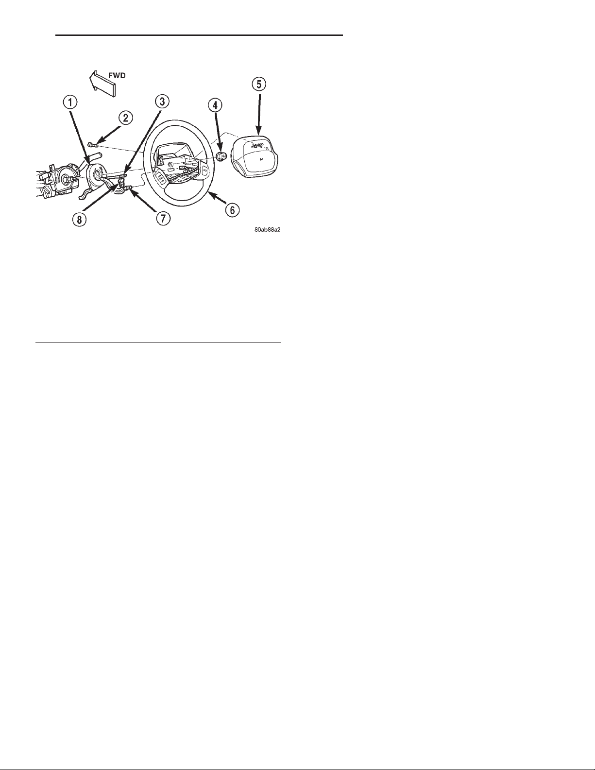
Be sure to vacuum the heater and air conditioning
outlets as well (Fig. 3). Run the heater and air conditioner blower on the lowest speed setting and vacuum any powder expelled from the outlets. You may
need to vacuum the interior of the vehicle a second
time to recover all of the powder.
Fig. 3 Vacuum Heater and A/C Outlets - Typical
Place the deployed airbag modules in your vehicular scrap pile.
REMOVAL AND INSTALLATION
DRIVER SIDE AIRBAG MODULE
The following procedure is for replacement of a
faulty or damaged driver side airbag module. If the
WAY TO DISABLE THE AIRBAG SYSTEM. FAILURE
TO DO THIS COULD RESULT IN ACCIDENTAL AIRBAG DEPLOYMENT AND POSSIBLE PERSONAL
INJURY.
• WHEN REMOVING A DEPLOYED AIRBAG MODULE, RUBBER GLOVES, EYE PROTECTION, AND A
LONG-SLEEVED SHIRT SHOULD BE WORN. THERE
MAY BE DEPOSITS ON THE AIRBAG MODULE AND
OTHER INTERIOR SURFACES. IN LARGE DOSES,
THESE DEPOSITS MAY CAUSE IRRITATION TO THE
SKIN AND EYES.
REMOVAL
(1) Disconnect and isolate the battery negative
cable. If either of the airbags has not been deployed,
wait two minutes for the system capacitor to discharge before further service.
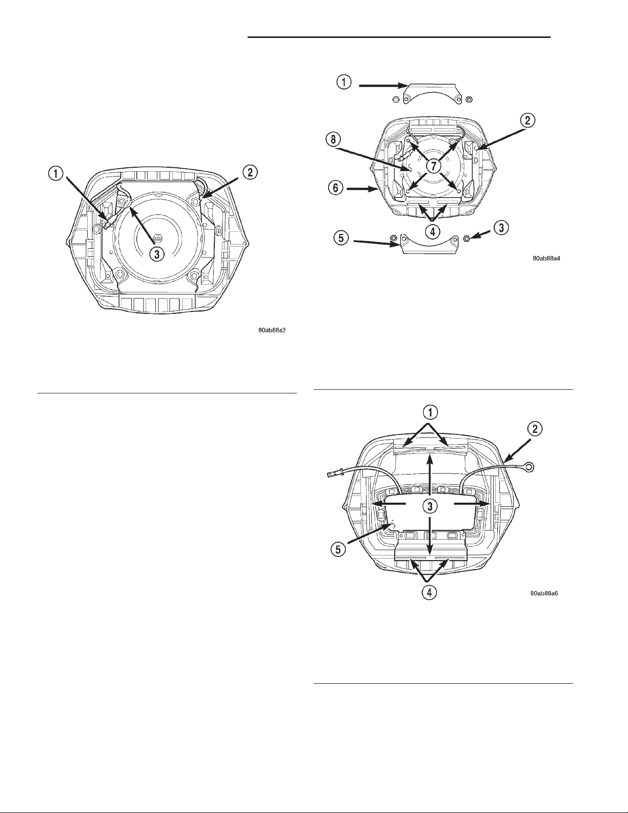
(2) From the underside of the steering wheel,
remove the two screws that secure the driver side
airbag module to the steering wheel (Fig. 4).
(3) Pull the airbag module away from the steering
wheel far enough to access the two wire harness connectors on the back of the airbag module.
(4) Disconnect the clockspring horn switch wire
harness connector from the horn switch feed wire
connector, which is located on the back of the airbag
module.
(5) The clockspring airbag wire harness connector
is a tight snap-fit into the airbag module connector
receptacle, which is located on the airbag inflator on
the back of the airbag module. Firmly grasp and pull
or gently pry on the clockspring airbag wire harness
connector to disconnect it from the airbag module.
Do not pull on the clockspring wire harness to
disengage the connector from the airbag module connector receptacle.
(6) Remove the driver side airbag module from the
steering wheel.
(7) If the driver side airbag has been deployed, the
clockspring must be replaced. Refer to Clockspring
Page 7
XJ PASSIVE RESTRAINT SYSTEMS 8M - 7
REMOVAL AND INSTALLATION (Continued)
(2) Reconnect the clockspring horn switch wire
harness connector to the horn switch feed wire connector, which is located on the back of the airbag
module.
(3) Carefully position the driver side airbag module in the steering wheel. Be certain that the clockspring wire harnesses in the steering wheel hub area
are not pinched between the airbag module and the
steering wheel.
(4) From the underside of the steering wheel,
install and tighten the two driver side airbag module
mounting screws. Tighten the screws to 10.2 N·m (90
in. lbs.).
(5) Do not reconnect the battery negative cable at
this time. Refer to Airbag System in the Diagnosis
Fig. 4 Driver Side Airbag Module Remove/Install
1 – CLOCKSPRING
2 – SCREW
3 – HORN SWITCH WIRE
4 – NUT
5 – DRIVER AIRBAG MODULE
6 – STEERING WHEEL
7 – SPEED CONTROL WIRE
8 – AIRBAG WIRE
and Testing section of this group for the proper procedures.
DRIVER SIDE AIRBAG MODULE TRIM COVER
The horn switch is integral to the driver side airbag module trim cover. If either component is faulty
or damaged, the entire driver side airbag module
trim cover and horn switch unit must be replaced.
in the Removal and Installation section of this group
for the clockspring service procedures.
INSTALLATION
WARNING:
• USE EXTREME CARE TO PREVENT ANY FOREIGN MATERIAL FROM ENTERING THE DRIVER
SIDE AIRBAG MODULE, OR BECOMING
ENTRAPPED BETWEEN THE AIRBAG CUSHION
AND THE DRIVER SIDE AIRBAG TRIM COVER.
FAILURE TO OBSERVE THIS WARNING COULD
RESULT IN OCCUPANT INJURIES UPON AIRBAG
DEPLOYMENT.
• THE DRIVER SIDE AIRBAG MODULE TRIM
COVER MUST NEVER BE PAINTED. REPLACEMENT
TRIM COVERS ARE SERVICED IN THE ORIGINAL
COLORS. PAINT MAY CHANGE THE WAY IN WHICH
THE MATERIAL OF THE TRIM COVER RESPONDS
TO AN AIRBAG DEPLOYMENT. FAILURE TO
OBSERVE THIS WARNING COULD RESULT IN
OCCUPANT INJURIES UPON AIRBAG DEPLOYMENT.
(1) When installing the driver side airbag module,
reconnect the clockspring airbag wire harness connector to the airbag module connector receptacle by
pressing straight in on the connector. You can be certain that the connector is fully engaged by listening
carefully for a distinct audible click as the connector
snaps into place.
WARNING:
• THE AIRBAG SYSTEM IS A SENSITIVE, COMPLEX ELECTROMECHANICAL UNIT. BEFORE
ATTEMPTING TO DIAGNOSE OR SERVICE ANY AIRBAG SYSTEM OR RELATED STEERING WHEEL,
STEERING COLUMN, OR INSTRUMENT PANEL
COMPONENTS YOU MUST FIRST DISCONNECT
AND ISOLATE THE BATTERY NEGATIVE (GROUND)
CABLE. THEN WAIT TWO MINUTES FOR THE SYSTEM CAPACITOR TO DISCHARGE BEFORE FURTHER SYSTEM SERVICE. THIS IS THE ONLY SURE
WAY TO DISABLE THE AIRBAG SYSTEM. FAILURE
TO DO THIS COULD RESULT IN ACCIDENTAL AIRBAG DEPLOYMENT AND POSSIBLE PERSONAL
INJURY.
• THE HORN SWITCH IS INTEGRAL TO THE AIRBAG MODULE TRIM COVER. SERVICE OF THIS
COMPONENT SHOULD BE PERFORMED ONLY BY
CHRYSLER-TRAINED AND AUTHORIZED DEALER
SERVICE TECHNICIANS. FAILURE TO TAKE THE
PROPER PRECAUTIONS OR TO FOLLOW THE
PROPER PROCEDURES COULD RESULT IN ACCIDENTAL, INCOMPLETE, OR IMPROPER AIRBAG
DEPLOYMENT AND POSSIBLE OCCUPANT INJURIES.
REMOVAL
(1) Disconnect and isolate the battery negative
cable. If either of the airbags has not been deployed,
wait two minutes for the system capacitor to discharge before further service.
Page 8
8M - 8 PASSIVE RESTRAINT SYSTEMS XJ
REMOVAL AND INSTALLATION (Continued)
(2) Remove the driver side airbag module from the
steering wheel. Refer to Driver Side Airbag Mod-
ule in the Removal and Installation section of this
group for the procedures.
(3) Remove the plastic horn switch feed wire
retainer from the stud on the back of the driver side
airbag housing (Fig. 5).
Fig. 6 Driver Side Airbag Trim Cover Retainers
Remove/Install
1 – UPPER RETAINER
2 – AIRBAG HOUSING
3 – NUT (4)
4 – RETAINER SLOTS
Fig. 5 Horn Switch Feed Wire Remove/Install
1 – HORN SWITCH FEED WIRE
2 – HORN SWITCH GROUND WIRE
3 – WIRE RETAINER
5 – LOWER RETAINER
6 – TRIM COVER
7 – STUDS
8 – INFLATOR
(4) Remove the four nuts that secure the upper
and lower trim cover retainers to the studs on the
back of the driver side airbag housing (Fig. 6).
(5) Remove the upper and lower trim cover retainers from the airbag housing studs.
(6) Remove the horn switch ground wire eyelet
from the upper airbag housing stud.
(7) Disengage the four trim cover locking blocks
from the lip around the outside edge of the driver
side airbag housing and remove the housing from the
cover (Fig. 7).
INSTALLATION
WARNING:
• USE EXTREME CARE TO PREVENT ANY FOREIGN MATERIAL FROM ENTERING THE DRIVER
SIDE AIRBAG MODULE, OR BECOMING
ENTRAPPED BETWEEN THE AIRBAG CUSHION
AND THE DRIVER SIDE AIRBAG TRIM COVER.
FAILURE TO OBSERVE THIS WARNING COULD
RESULT IN OCCUPANT INJURIES UPON AIRBAG
DEPLOYMENT.
• THE DRIVER SIDE AIRBAG MODULE TRIM
COVER MUST NEVER BE PAINTED. REPLACEMENT
TRIM COVERS ARE SERVICED IN THE ORIGINAL
COLORS. PAINT MAY CHANGE THE WAY IN WHICH
THE MATERIAL OF THE TRIM COVER RESPONDS
TO AN AIRBAG DEPLOYMENT. FAILURE TO
Fig. 7 Driver Side Airbag Trim Cover Remove/Install
1 – RETAINER SLOTS
2 – TRIM COVER
3 – LOCKING BLOCKS
4 – RETAINER SLOTS
5 – HORN SWITCH
OBSERVE THIS WARNING COULD RESULT IN
OCCUPANT INJURIES UPON AIRBAG DEPLOYMENT.
(1) Carefully position the driver side airbag mod-
ule in the trim cover. Be certain that the horn switch
Page 9
XJ PASSIVE RESTRAINT SYSTEMS 8M - 9
REMOVAL AND INSTALLATION (Continued)
feed and ground wires are not pinched between the
airbag housing and the trim cover locking blocks.
(2) Engage the upper and lower trim cover locking
blocks with the lip of the driver side airbag housing,
then engage the locking blocks on each side of the
trim cover with the lip of the housing. Be certain
that each of the locking blocks is fully engaged on
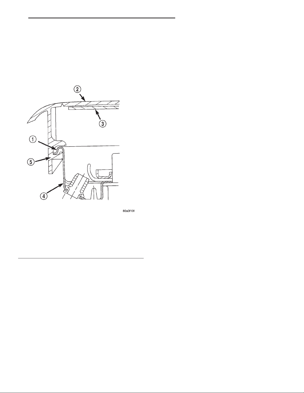
the lip of the airbag housing (Fig. 8).
the passenger side airbag module has been deployed,
the passenger side airbag door must also be replaced.
Refer to Passenger Side Airbag Door in the
Removal and Installation section of this group for the
additional service procedures for the passenger side
airbag door.
WARNING:
• THE AIRBAG SYSTEM IS A SENSITIVE, COMPLEX ELECTROMECHANICAL UNIT. BEFORE
ATTEMPTING TO DIAGNOSE OR SERVICE ANY AIRBAG SYSTEM OR RELATED STEERING WHEEL,
STEERING COLUMN, OR INSTRUMENT PANEL
COMPONENTS YOU MUST FIRST DISCONNECT
AND ISOLATE THE BATTERY NEGATIVE (GROUND)
CABLE. THEN WAIT TWO MINUTES FOR THE SYSTEM CAPACITOR TO DISCHARGE BEFORE FURTHER SYSTEM SERVICE. THIS IS THE ONLY SURE
WAY TO DISABLE THE AIRBAG SYSTEM. FAILURE
TO DO THIS COULD RESULT IN ACCIDENTAL AIRBAG DEPLOYMENT AND POSSIBLE PERSONAL
INJURY.
• WHEN REMOVING A DEPLOYED AIRBAG MODULE, RUBBER GLOVES, EYE PROTECTION, AND A
LONG-SLEEVED SHIRT SHOULD BE WORN. THERE
MAY BE DEPOSITS ON THE AIRBAG MODULE AND
OTHER INTERIOR SURFACES. IN LARGE DOSES,
THESE DEPOSITS MAY CAUSE IRRITATION TO THE
SKIN AND EYES.
Fig. 8 Driver Side Airbag Trim Cover Locking
Blocks Engaged
1 – LIP
2 – TRIM COVER
3 – HORN SWITCH
4 – AIRBAG HOUSING
5 – LOCKING BLOCK
(3) Install the horn switch ground wire eyelet over
the upper airbag housing stud.
(4) Install the upper and lower airbag trim cover
retainers over the airbag housing studs. Be certain
that the tabs on each retainer are engaged in the
retainer slots of the upper and lower trim cover locking blocks (Fig. 7).
(5) Install and tighten the trim cover retainer
mounting nuts on the airbag housing studs. Tighten
the nuts to 10 N·m (90 in. lbs.).
(6) Install the driver side airbag module onto the
steering wheel. Refer to Driver Side Airbag Mod-
ule in the Removal and Installation section of this
group for the procedures.
PASSENGER SIDE AIRBAG MODULE
The following procedure is for replacement of a
faulty or damaged passenger side airbag module. If
REMOVAL
(1) Disconnect and isolate the battery negative
cable. If either of the airbags has not been deployed,
wait two minutes for the system capacitor to discharge before further service.
(2) Remove the top cover from the instrument
panel. Refer to Instrument Panel Top Cover in the
Removal and Installation section of Group 8E Instrument Panel Systems for the procedures.
(3) Disconnect the passenger side airbag module
wire harness connector from the instrument panel
wire harness. This connector is located on the top of
the instrument panel structural support between the
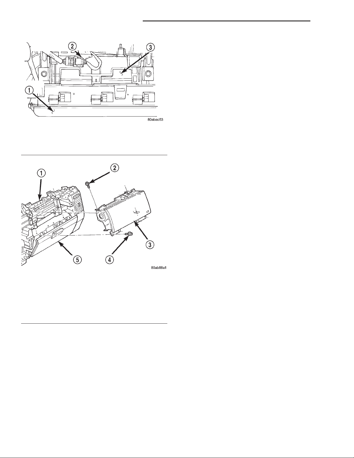
airbag module and the windshield (Fig. 9).
(4) Disengage the passenger side airbag module
wire harness connector retainer from the mounting
hole on the top of the instrument panel structural
support.
(5) Remove the four screws that secure the upper
flange of the passenger side airbag door to the
instrument panel structural support (Fig. 10).
(6) Remove the two screws that secure the passenger side airbag module upper mounting brackets to
the top of the instrument panel structural support.
(7) Roll down the glove box from the instrument
panel. Refer to Glove Box - Roll Down in the
Page 10
8M - 10 PASSIVE RESTRAINT SYSTEMS XJ
REMOVAL AND INSTALLATION (Continued)
(11) Remove the passenger side airbag door from
the airbag module. Refer to Passenger Side Airbag
Door in the Removal and Installation section of this
group for the procedures.
INSTALLATION
WARNING: USE EXTREME CARE TO PREVENT
ANY FOREIGN MATERIAL FROM ENTERING THE
PASSENGER SIDE AIRBAG MODULE, OR BECOMING ENTRAPPED BETWEEN THE AIRBAG CUSHION
AND THE PASSENGER SIDE AIRBAG DOOR. FAIL-
Fig. 9 Passenger Side Airbag Module Connector
1 – AIRBAG DOOR
2 – PASSENGER SIDE AIRBAG WIRE HARNESS CONNECTOR
3 – AIRBAG HOUSING
Fig. 10 Passenger Side Airbag Module Remove/
Install
1 – INSTRUMENT PANEL
2 – SCREW
3 – PASSENGERAIRBAG MODULE
4 – SCREW
5 – GLOVE BOX DOOR
Removal and Installation section of Group 8E Instrument Panel Systems for the procedures.
(8) Remove the four screws that secure the lower
flange of the passenger side airbag door to the
instrument panel upper glove box opening reinforcement.
(9) Reach through and above the instrument panel
glove box opening to access and remove the two
screws that secure the passenger side airbag module
lower mounting brackets to the instrument panel
structural support.
(10) Remove the passenger side airbag module and
airbag door from the instrument panel as a unit.
URE TO OBSERVE THIS WARNING COULD RESULT
IN OCCUPANT INJURIES UPON AIRBAG DEPLOYMENT.
(1) Install the passenger side airbag door onto the
airbag module. Refer to Passenger Side Airbag
Door in the Removal and Installation section of this
group for the procedures.
(2) Carefully position the passenger side airbag
module and airbag door in the instrument panel as a
unit.
(3) Reach through and above the instrument panel
glove box opening to install and tighten the two
screws that secure the passenger side airbag module
lower mounting brackets to the instrument panel
structural support. Tighten the screws to 11.8 N·m
(105 in. lbs.).
(4) Install and tighten the four screws that secure
the lower flange of the passenger side airbag door to
the instrument panel upper glove box opening reinforcement. Tighten the screws to 2.2 N·m (20 in.
lbs.).
(5) Install the glove box into the instrument panel.
Refer to Glove Box - Roll Down in the Removal
and Installation section of Group 8E - Instrument
Panel Systems for the procedures.
(6) Install and tighten the two screws that secure
the passenger side airbag module upper mounting
brackets to the top of the instrument panel structural support. Tighten the screws to 11.8 N·m (105
in. lbs.).
(7) Install and tighten the four screws that secure
the upper flange of the passenger side airbag door to
the instrument panel structural support. Tighten the
screws to 2.2 N·m (20 in. lbs.).
(8) Engage the passenger side airbag module wire
harness connector retainer in the mounting hole on
the top of the instrument panel structural support.
(9) Reconnect the passenger side airbag module
wire harness connector to the instrument panel wire
harness. Be certain that the connector is fully
engaged and latched.
(10) Install the top cover onto the instrument
panel. Refer to Instrument Panel Top Cover in the
Page 11
XJ PASSIVE RESTRAINT SYSTEMS 8M - 11
REMOVAL AND INSTALLATION (Continued)
Removal and Installation section of Group 8E Instrument Panel Systems for the procedures.
(11) Do not reconnect the battery negative cable at
this time. Refer to Airbag System in the Diagnosis
and Testing section of this group for the proper procedures.
PASSENGER SIDE AIRBAG DOOR
WARNING:
• THE AIRBAG SYSTEM IS A SENSITIVE, COMPLEX ELECTROMECHANICAL UNIT. BEFORE
ATTEMPTING TO DIAGNOSE OR SERVICE ANY AIRBAG SYSTEM OR RELATED STEERING WHEEL,
STEERING COLUMN, OR INSTRUMENT PANEL
COMPONENTS YOU MUST FIRST DISCONNECT
AND ISOLATE THE BATTERY NEGATIVE (GROUND)
CABLE. THEN WAIT TWO MINUTES FOR THE SYSTEM CAPACITOR TO DISCHARGE BEFORE FURTHER SYSTEM SERVICE. THIS IS THE ONLY SURE
WAY TO DISABLE THE AIRBAG SYSTEM. FAILURE
TO DO THIS COULD RESULT IN ACCIDENTAL AIRBAG DEPLOYMENT AND POSSIBLE PERSONAL
INJURY.
• WHEN REMOVING A DEPLOYED AIRBAG MODULE, RUBBER GLOVES, EYE PROTECTION, AND A
LONG-SLEEVED SHIRT SHOULD BE WORN. THERE
MAY BE DEPOSITS ON THE AIRBAG MODULE AND
OTHER INTERIOR SURFACES. IN LARGE DOSES,
THESE DEPOSITS MAY CAUSE IRRITATION TO THE
SKIN AND EYES.
REMOVAL
(1) Disconnect and isolate the battery negative
cable. If either of the airbags has not been deployed,
wait two minutes for the system capacitor to discharge before further service.
(2) Remove the passenger side airbag module from
the instrument panel. Refer to Passenger Side Air-
bag Module in the Removal and Installation section
of this group for the procedures.
(3) Place the passenger side airbag module on a
suitable work surface. Slide the passenger side airbag door sideways on the airbag module until the
keyed holes in the returns of the upper and lower
airbag door mounting flanges clear the three tabs on
the top and the bottom of the airbag module housing
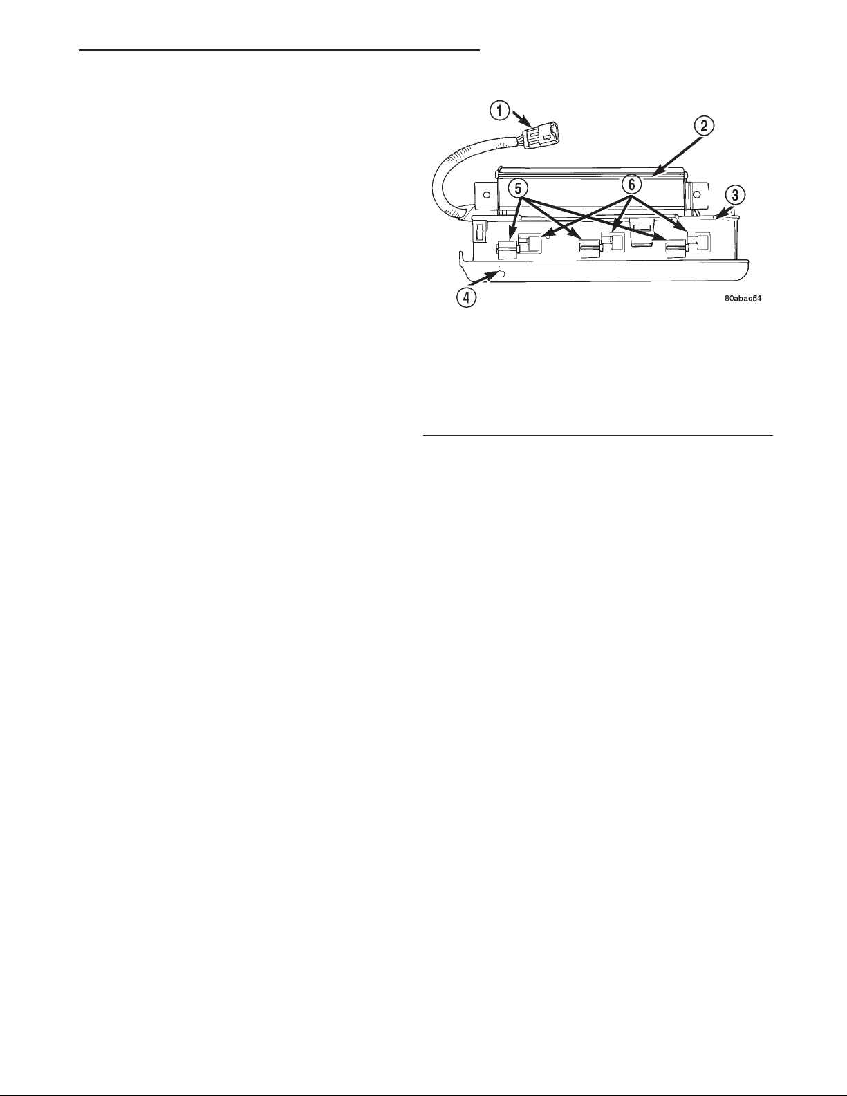
(Fig. 11).
(4) Disengage the keyed holes in the returns of the
upper and lower airbag door mounting flange returns
from the three tabs on the top and the bottom of the
passenger side airbag module housing.
(5) Remove the passenger side airbag door from
the airbag module.
Fig. 11 Passenger Side Airbag Door Remove/Install
1 – CONNECTOR
2 – AIRBAG MODULE HOUSING
3 – AIRBAG DOOR FLANGE
4 – AIRBAG DOOR
5–TABS
6 – KEYED SLOTS
INSTALLATION
WARNING:
• USE EXTREME CARE TO PREVENT ANY FOREIGN MATERIAL FROM ENTERING THE PASSENGER SIDE AIRBAG MODULE, OR BECOMING
ENTRAPPED BETWEEN THE AIRBAG CUSHION
AND THE PASSENGER SIDE AIRBAG DOOR. FAILURE TO OBSERVE THIS WARNING COULD RESULT
IN OCCUPANT INJURIES UPON AIRBAG DEPLOYMENT.
• THE PASSENGER SIDE AIRBAG DOOR MUST
NEVER BE PAINTED. REPLACEMENT AIRBAG
DOORS ARE SERVICED IN THE ORIGINAL COLORS. PAINT MAY CHANGE THE WAY IN WHICH THE
MATERIAL OF THE AIRBAG DOOR RESPONDS TO
AN AIRBAG DEPLOYMENT. FAILURE TO OBSERVE
THIS WARNING COULD RESULT IN OCCUPANT
INJURIES UPON AIRBAG DEPLOYMENT.
(1) Position the passenger side airbag door over
the airbag module.
(2) Engage the keyed holes in the returns of the
upper and lower airbag door mounting flanges with
the three tabs on the top and the bottom of the passenger side airbag module housing.
(3) Slide the passenger side airbag door sideways
until the keyed holes in the returns of the upper and
lower airbag door mounting flanges are locked onto
the three tabs on the top and the bottom of the airbag module housing.
(4) Install the passenger side airbag module onto
the instrument panel. Refer to Passenger Side Air-
bag Module in the Removal and Installation section
of this group for the procedures.
Page 12
8M - 12 PASSIVE RESTRAINT SYSTEMS XJ
REMOVAL AND INSTALLATION (Continued)
AIRBAG CONTROL MODULE
WARNING:
• THE AIRBAG CONTROL MODULE CONTAINS
THE IMPACT SENSOR, WHICH ENABLES THE SYSTEM TO DEPLOY THE AIRBAG. BEFORE ATTEMPTING TO DIAGNOSE OR SERVICE ANY AIRBAG
SYSTEM OR RELATED STEERING WHEEL, STEERING COLUMN, OR INSTRUMENT PANEL COMPONENTS YOU MUST FIRST DISCONNECT AND
ISOLATE THE BATTERY NEGATIVE (GROUND)
CABLE. THEN WAIT TWO MINUTES FOR THE SYSTEM CAPACITOR TO DISCHARGE BEFORE FURTHER SYSTEM SERVICE. THIS IS THE ONLY SURE
WAY TO DISABLE THE AIRBAG SYSTEM. FAILURE
TO DO THIS COULD RESULT IN ACCIDENTAL AIRBAG DEPLOYMENT AND POSSIBLE PERSONAL
INJURY.
• NEVER STRIKE OR KICK THE AIRBAG CONTROL MODULE, AS IT CAN DAMAGE THE IMPACT
SENSOR OR AFFECT ITS CALIBRATION. IF AN AIRBAG CONTROL MODULE IS ACCIDENTALLY
DROPPED DURING SERVICE, THE MODULE MUST
BE SCRAPPED AND REPLACED WITH A NEW UNIT.
ALWAYS REINSTALL THE AIRBAG CONTROL MODULE PROTECTIVE COVER. FAILURE TO OBSERVE
THIS WARNING COULD RESULT IN ACCIDENTAL,
INCOMPLETE, OR IMPROPER AIRBAG DEPLOYMENT AND POSSIBLE OCCUPANT INJURIES.
(a) Squeeze the two connector latch tabs
between the thumb and forefinger.
(b) Pull the connector straight away from the
ACM connector receptacle.
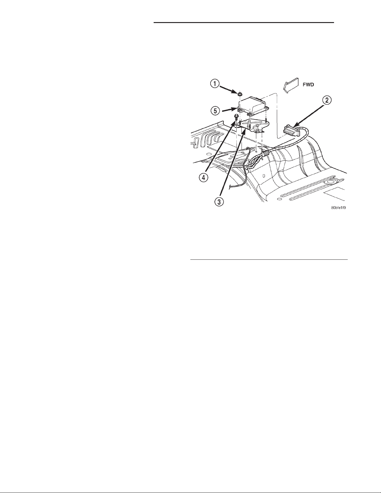
Fig. 12 Airbag Control Module Remove/Install
1 – NUT AND WASHER (3)
2 – INSTRUMENT PANEL WIRE HARNESS CONNECTOR
3 – ACM MOUNTING BRACKET
4 – SCREW (4)
5 – AIRBAG CONTROL MODULE
REMOVAL
(1) Disconnect and isolate the battery negative
cable. If either of the airbags has not been deployed,
wait two minutes for the system capacitor to discharge before further service.
(2) Remove the center floor console from the floor
panel transmission tunnel. Refer to Full Floor Con-
sole in the index of this service manual for the location of the proper center floor console removal
procedures.
(3) Remove the console rear duct from the floor
panel transmission tunnel. Refer to Ducts And Out-
lets in the index of this service manual for the location of the proper console rear duct removal
procedures.
(4) Remove the three screws that secure the center
floor console rear mounting bracket to the floor panel
transmission tunnel.
(5) Remove the center floor console rear mounting
bracket from the floor panel transmission tunnel.
(6) Disconnect the instrument panel wire harness
connector from the Airbag Control Module (ACM)
(Fig. 12). To disconnect the instrument panel wire
harness connector from the ACM:
(7) Remove the three nuts that secure the ACM to
the weld studs on the ACM mounting bracket on the
floor panel transmission tunnel.
(8) Remove the ACM from the ACM mounting
bracket on the floor panel transmission tunnel.
INSTALLATION
(1) Carefully position the ACM onto the ACM
mounting bracket on the floor panel transmission
tunnel. When the ACM is correctly positioned the
arrow on the ACM label will be pointed forward in
the vehicle.
(2) Install and tighten the three nuts that secure
the ACM to the weld studs on the ACM mounting
bracket on the floor panel transmission tunnel.
Tighten the nuts to 7.3 N·m (65 in. lbs.).
(3) Reconnect the instrument panel wire harness
connector to the ACM connector receptacle. Be certain that the connector latches are fully engaged.
(4) Position the center floor console rear mounting
bracket onto the floor panel transmission tunnel over
the ACM.
(5) Install and tighten the three screws that secure
the center floor console rear mounting bracket to the
floor panel transmission tunnel. Tighten the screws
to 1.1 N·m (10 in. lbs.).
Page 13
XJ PASSIVE RESTRAINT SYSTEMS 8M - 13
REMOVAL AND INSTALLATION (Continued)
(6) Install the console rear duct onto the floor
panel transmission tunnel. Refer to Ducts And Out-
lets in the index of this service manual for the location of the proper console rear duct installation
procedures.
(7) Install the center floor console onto the floor
panel transmission tunnel. Refer to Full Floor Con-
sole in the index of this service manual for the location of the proper center floor console installation
procedures.
(8) Do not reconnect the battery negative cable at
this time. Refer to Airbag System in the Diagnosis
and Testing section of this group for the proper procedures.
CLOCKSPRING
The clockspring cannot be repaired. It must be
replaced if faulty or damaged, or if the driver side
airbag has been deployed.
WARNING: THE AIRBAG SYSTEM IS A SENSITIVE,
COMPLEX ELECTROMECHANICAL UNIT. BEFORE
ATTEMPTING TO DIAGNOSE OR SERVICE ANY AIRBAG SYSTEM OR RELATED STEERING WHEEL,
STEERING COLUMN, OR INSTRUMENT PANEL
COMPONENTS YOU MUST FIRST DISCONNECT
AND ISOLATE THE BATTERY NEGATIVE (GROUND)
CABLE. THEN WAIT TWO MINUTES FOR THE SYSTEM CAPACITOR TO DISCHARGE BEFORE FURTHER SYSTEM SERVICE. THIS IS THE ONLY SURE
WAY TO DISABLE THE AIRBAG SYSTEM. FAILURE
TO DO THIS COULD RESULT IN ACCIDENTAL AIRBAG DEPLOYMENT AND POSSIBLE PERSONAL
INJURY.
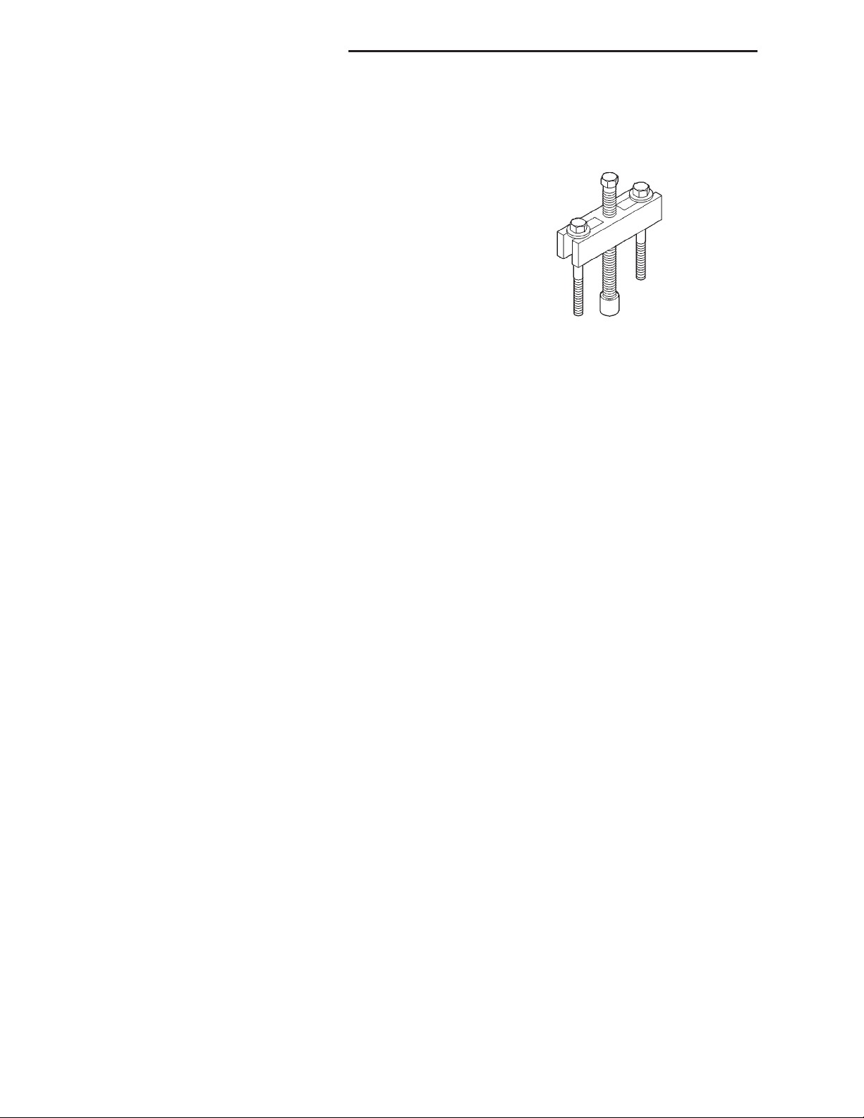
(5) Pull the steering wheel off of the steering column upper shaft spline using a steering wheel puller
(Special Tool C-3428-B).
(6) Remove the steering column opening cover
from the instrument panel. Refer to Steering Col-
umn Opening Cover in the Removal and Installation section of Group 8E - Instrument Panel Systems
for the procedures.
(7) If the vehicle is so equipped, move the tilt
steering column to the fully raised position.
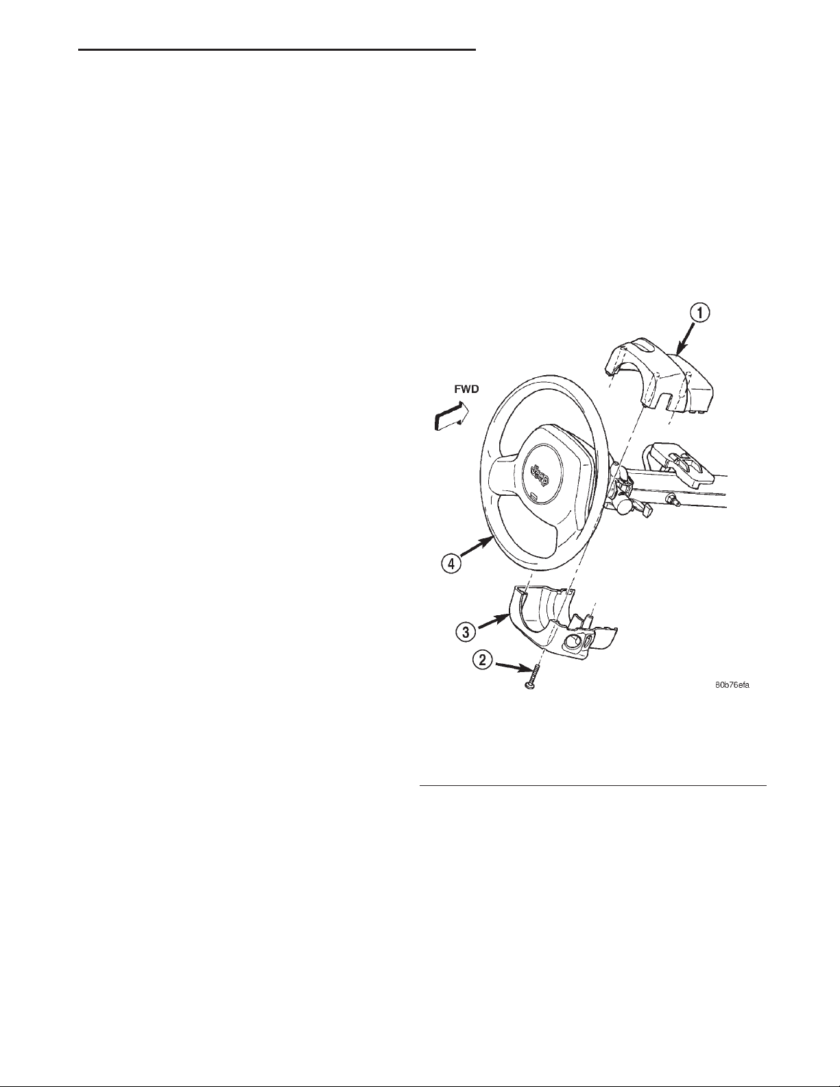
(8) Remove the three screws that secure the lower
steering column shroud to the upper shroud (Fig. 13).
REMOVAL
NOTE: Before starting this procedure, be certain to
turn the steering wheel until the front wheels are in
the straight-ahead position.
(1) Place the front wheels in the straight-ahead
position.
(2) Remove the driver side airbag module from the
steering wheel. Refer to Driver Side Airbag Mod-
ule in the Removal and Installation section of this
group for the procedures.
(3) If the vehicle is so equipped, disconnect the
upper clockspring wire harness connector from the
steering wheel wire harness for the vehicle speed
control switches located within the hub cavity of the
steering wheel.
(4) Remove the nut that secures the steering wheel
armature to the steering column upper shaft, which
is located within the hub cavity of the steering wheel.
Fig. 13 Steering Column Shrouds Remove/Install
1 – UPPER SHROUD
2 – SCREW (3)
3 – LOWER SHROUD
4 – STEERING WHEEL
(9) If the vehicle is equipped with a standard nontilt steering column, loosen the two upper steering
column mounting nuts. If the vehicle is equipped
with the optional tilt steering column, move the tilt
steering column to the fully lowered position.
(10) Remove both the upper and lower shrouds
from the steering column.
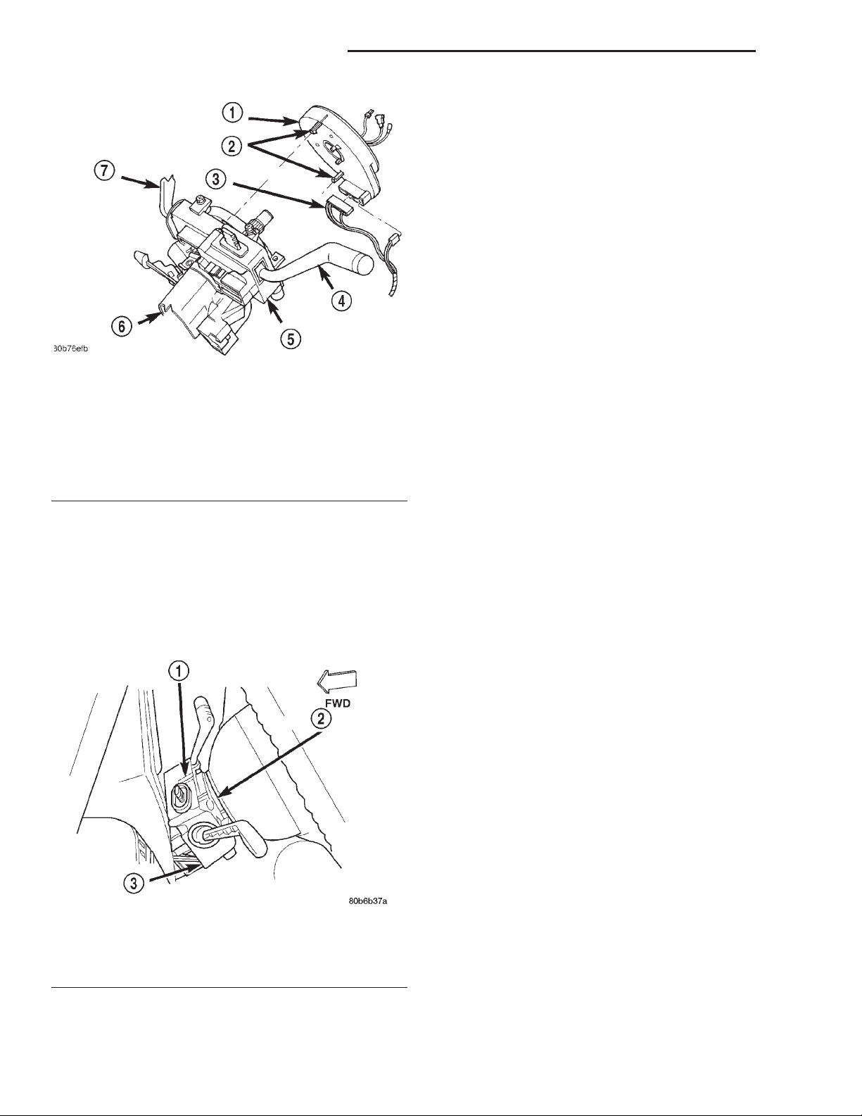
(11) Disconnect the two instrument panel wire
harness connectors from the lower clockspring connector receptacles (Fig. 14).
(12) The multi-function switch water shield
bracket on the top of the steering column has a small
access window which allows access to the upper
Page 14
8M - 14 PASSIVE RESTRAINT SYSTEMS XJ
REMOVAL AND INSTALLATION (Continued)
replaced if faulty or damaged, or if the driver side
airbag has been deployed.
(14) If the removed clockspring is to be reused,
lock the clockspring rotor to the clockspring case to
maintain clockspring centering until it is reinstalled
on the steering column. This can be done by inserting
a stiff wire through the small index hole located at
about the 11 o’clock position in the centered clockspring rotor and case. Refer to Clockspring Center-
ing in the Adjustments section of this group for an
illustration of the clockspring index hole. Bend the
wire over after it has been inserted through the
index hole to prevent it from falling out.
INSTALLATION
If the clockspring is not properly centered in rela-
Fig. 14 Clockspring Remove/Install
1 – CLOCKSPRING
2 – LATCHES
3 – WIRE HARNESS
4 – TURN SIGNAL SWITCH LEVER
5 – WATER SHIELD BRACKET
6 – STEERING COLUMN
7 – WIPER SWITCH LEVER
clockspring latch with a small screwdriver (Fig. 15).
Gently pry both plastic latches of the clockspring
assembly to release them from the steering column
upper housing.
NOTE: If the clockspring plastic latches are broken,
be certain to remove the broken pieces from the
steering column upper housing.
Fig. 15 Upper Clockspring Latch Access Window
1 – UPPER CLOCKSPRING LATCH ACCESS WINDOW
2 – CLOCKSPRING
3 – WATER SHIELD AND BRACKET
(13) Remove the clockspring from the steering col-
umn. The clockspring cannot be repaired. It must be
tion to the steering wheel, steering shaft and steering gear, it may be damaged. Refer to Clockspring
Centering in the Adjustments section of this group
before installing or reinstalling a clockspring.
Service replacement clocksprings are shipped precentered and with a locking pin installed. This locking pin should not be removed until the clockspring
has been installed on the steering column. If the
locking pin is removed before the clockspring is
installed on a steering column, the clockspring centering procedure must be performed.
NOTE: Before starting this procedure, be certain
that the front wheels are still in the straight-ahead
position.
(1) If the removed clockspring is being reused,
remove the wire from the index hole that is locking
the clockspring rotor to the clockspring case to maintain clockspring centering.
(2) Be certain that the turn signal switch stalk is
in the neutral position, then carefully slide the centered clockspring down over the steering column
upper shaft until the clockspring latches engage the
steering column upper housing.
(3) If a new clockspring has been installed, remove
the locking pin that is securing the clockspring rotor
to the clockspring case and maintaining clockspring
centering.
(4) Reconnect the two instrument panel wire harness connectors to the lower clockspring connector
receptacles. Be certain that the connector latches are
fully engaged.
(5) Position the steering column shrouds on the
steering column.
(6) Install and tighten the three screws that secure
the lower steering column shroud to the upper
shroud. Tighten the screws to 2 N·m (18 in. lbs.).
(7) Install the steering column opening cover onto
the instrument panel. Refer to Steering Column
Opening Cover in the Removal and Installation sec-
Page 15
XJ PASSIVE RESTRAINT SYSTEMS 8M - 15
REMOVAL AND INSTALLATION (Continued)
tion of Group 8E - Instrument Panel Systems for the
procedures.
(8) Install the steering wheel onto the steering column upper shaft. Be certain to index the flats on the
hub of the steering wheel with the formations on the
inside of the clockspring rotor. Pull the upper clockspring wire harnesses through the lower hole in the
steering wheel armature.
(9) Install and tighten the steering wheel mounting nut. Tighten the nut to 61 N·m (45 ft. lbs.). Be
certain not to pinch the wire harnesses between the
steering wheel and the nut.
(10) If the vehicle is so equipped, reconnect the
upper clockspring wire harness connector to the
steering wheel wire harness for the vehicle speed
control switches.
(11) Install the driver side airbag module onto the
steering wheel. Refer to Driver Side Airbag Mod-
ule in the Removal and Installation section of this
group for the procedures.
ADJUSTMENTS
CLOCKSPRING CENTERING
The clockspring is designed to wind and unwind
when the steering wheel is rotated, but is only
designed to rotate the same number of turns (about
five complete rotations) as the steering wheel can be
turned from stop to stop. Centering the clockspring
indexes the clockspring tape to other steering components so that it can operate within its designed
travel limits. The rotor of a centered clockspring can
be rotated two and one-half turns in either direction
from the centered position, without damaging the
clockspring tape.
However, if the clockspring is removed for service
or if the steering column is disconnected from the
steering gear, the clockspring tape can change position relative to the other steering components. The
clockspring must then be re-centered following completion of the service or the clockspring tape may be
damaged.
Service replacement clocksprings are shipped precentered and with a locking pin installed. This locking pin should not be removed until the clockspring
has been installed on the steering column. If the
locking pin is removed before the clockspring is
installed on a steering column, the clockspring centering procedure must be performed.
AND ISOLATE THE BATTERY NEGATIVE (GROUND)
CABLE. THEN WAIT TWO MINUTES FOR THE SYSTEM CAPACITOR TO DISCHARGE BEFORE FURTHER SYSTEM SERVICE. THIS IS THE ONLY SURE
WAY TO DISABLE THE AIRBAG SYSTEM. FAILURE
TO DO THIS COULD RESULT IN ACCIDENTAL AIRBAG DEPLOYMENT AND POSSIBLE PERSONAL
INJURY.
NOTE: Before starting this procedure, be certain to
turn the steering wheel until the front wheels are in
the straight-ahead position.
(1) Place the front wheels in the straight-ahead
position.
(2) Remove the clockspring from the steering column. Refer to Clockspring in the Removal and
Installation section of this group for the procedures.
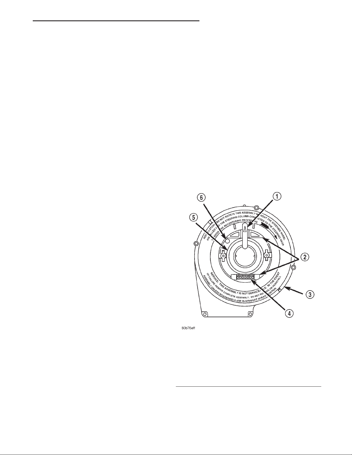
(3) Hold the clockspring case in one hand so that it
is oriented as it would be when it is installed on the
steering column (Fig. 16).
Fig. 16 Clockspring
1 – LOCKING PIN
2 – ROTOR FLATS
3 – CASE
4 – UPPER CLOCKSPRING WIRE HARNESSES (WIRES NOT
SHOWN)
5 – ROTOR
6 – INDEX HOLE
WARNING: THE AIRBAG SYSTEM IS A SENSITIVE,
COMPLEX ELECTROMECHANICAL UNIT. BEFORE
ATTEMPTING TO DIAGNOSE OR SERVICE ANY AIRBAG SYSTEM OR RELATED STEERING WHEEL,
STEERING COLUMN, OR INSTRUMENT PANEL
COMPONENTS YOU MUST FIRST DISCONNECT
(4) Use your other hand to rotate the clockspring
rotor clockwise to the end of its travel. Do not apply
excessive torque.
(5) From the end of the clockwise travel, rotate the
rotor about two and one-half turns counterclockwise,
Page 16
8M - 16 PASSIVE RESTRAINT SYSTEMS XJ
ADJUSTMENTS (Continued)
until the rotor flats are horizontal. If the upper clockspring wire harnesses are not oriented towards the
bottom of the clockspring, rotate the rotor another
one-half turn in the counterclockwise direction.
(6) The clockspring is now centered. Lock the
clockspring rotor to the clockspring case to maintain
clockspring centering until it is reinstalled on the
steering column. This can be done by inserting a stiff
wire through the small index hole located at about
the 11 o’clock position in the centered clockspring
rotor and case. Bend the wire over after it has been
inserted through the index hole to prevent it from
falling out.
(7) The front wheels should still be in the straightahead position. Install the clockspring onto the steering column. Refer to Clockspring in the Removal
and Installation section of this group for the procedures.
SPECIAL TOOLS
PASSIVE RESTRAINT SYSTEMS
Puller C-3428-B
 Loading...