

Page 1
XJ LAMPS 8L - 1
LAMPS
TABLE OF CONTENTS
page page
LAMP DIAGNOSIS ......................... 1
HEADLAMP AND FOG LAMP ALIGNMENT....... 3
LAMP BULB SERVICE ...................... 6
LAMP DIAGNOSIS
TABLE OF CONTENTS
page page
DESCRIPTION AND OPERATION
HEADLAMP LEVELING MOTOR...............1
DIAGNOSIS AND TESTING
DIAGNOSTIC PROCEDURES ................1
DESCRIPTION AND OPERATION
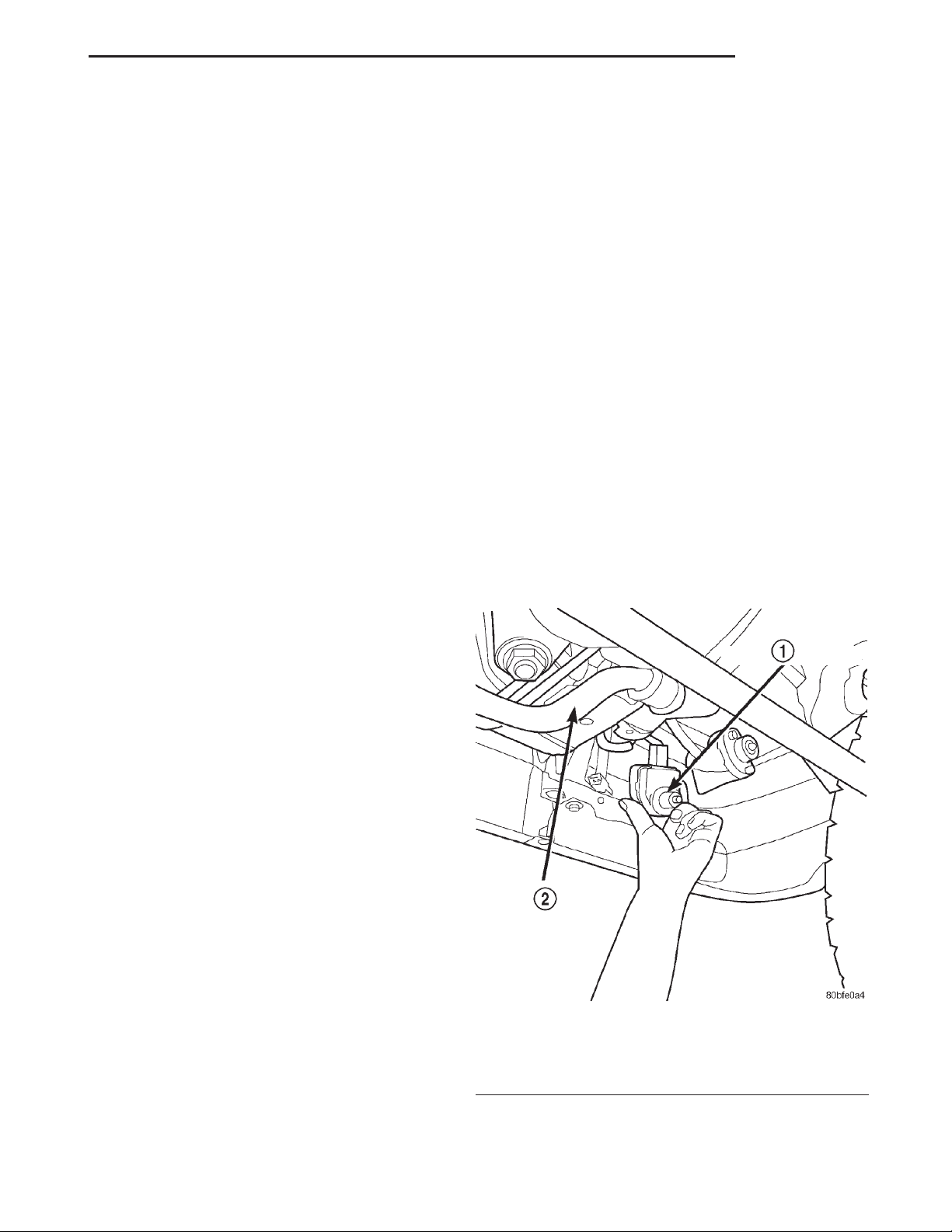
HEADLAMP LEVELING MOTOR
DESCRIPTION
Vehicles equipped with a remote headlamp leveling
system use two leveling motors attached to each
headlamp mounting bracket. They are located just
behind the headlamp assemblies and must be
accessed from underneath the vehicle.
LAMP SERVICE............................ 8
BULB APPLICATION ....................... 11
DIAGNOSIS AND TESTING ..................2
OPERATION
This system allows the driver to adjust the vertical
headlamp aim from the interior of the vehicle to compensate for passenger or cargo load. A headlamp leveling switch is located in the instrument panel and
controls the headlamp leveling motor function.
DIAGNOSIS AND TESTING
DIAGNOSTIC PROCEDURES
When a vehicle experiences problems with the
headlamp system, verify the condition of the battery
connections, fuses, charging system, headlamp bulbs,
wire connectors, relay, high beam switch, dimmer
switch, and headlamp switch. Refer to Group 8W,
Wiring Diagrams for component locations and circuit
information.
Fig. 1 Headlamp Leveling Motor Position &
Orientation
1 – HEADLAMP LEVELING MOTOR
2 – FRONT STABILIZER BAR
Page 2
8L - 2 LAMPS XJ
DIAGNOSIS AND TESTING (Continued)
DIAGNOSIS AND TESTING
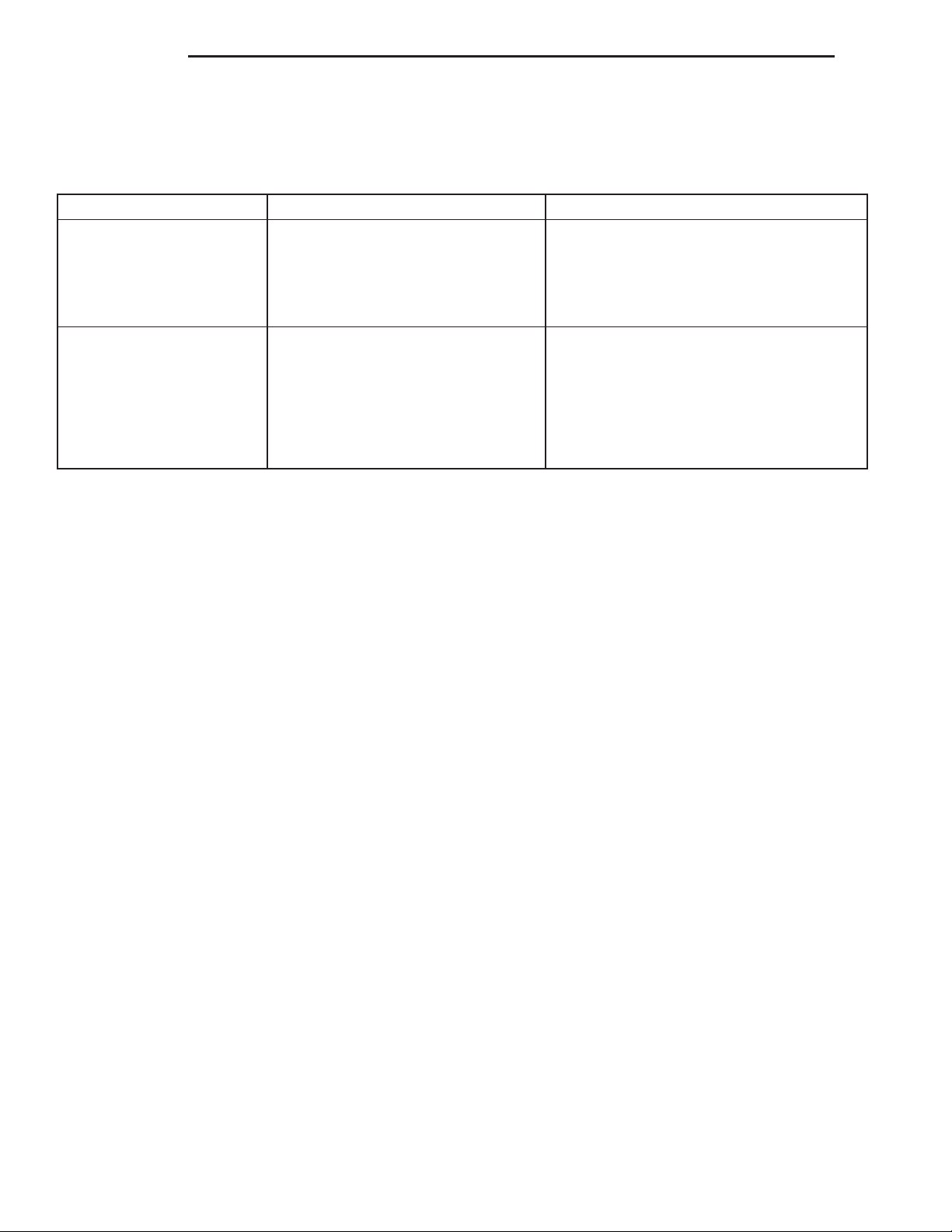
HEADLAMP LEVELING MOTOR DIAGNOSIS
CONDITION POSSIBLE CAUSES CORRECTION
ONE MOTOR DOES NOT
OPERATE
BOTH MOTORS DO NOT
OPERATE
1. Poor connection at motor. 1. Secure connector on motor.
2. No voltage at motor. 2. Repair circuit. Refer to Group 8W,
Wiring.
3. Defective motor. 3. Replace motor.
1. No voltage at headlamp leveling
switch.
2. No voltage at both motors. 2. Repair circuit or replace fuse. Refer to
3. Poor connection at motors. 3. Secure connectors on motors.
4. Both motors defective. 4. Replace motors.
1. Repair circuit or replace fuse. Refer to
Group 8W, Wiring.
Group 8W, Wiring.
Page 3

XJ LAMPS 8L - 3
HEADLAMP AND FOG LAMP ALIGNMENT
TABLE OF CONTENTS
page page
SERVICE PROCEDURES
HEADLAMP ALIGNMENT PREPARATION........3
SERVICE PROCEDURES
HEADLAMP ALIGNMENT PREPARATION
(1) Verify headlamp are on low beam setting.
(2) Verify that the headlamp leveling switch is in
the “0” position.
(3) Inspect and correct damaged or defective components that could interfere with proper headlamp
alignment.
(4) Verify proper tire inflation.
(5) Clean headlamp lenses.
(6) Verify that luggage area is loaded as the vehicle is routinely used.
(7) Fuel tank should be FULL. Add 2.94 kg (6.5
lbs.) of weight over the fuel tank for each estimated
gallon of missing fuel.
ADJUSTMENTS
HEADLAMP/FOG LAMP ADJUSTMENT USING ALIGNMENT SCREEN
ALIGNMENT SCREEN PREPARATION
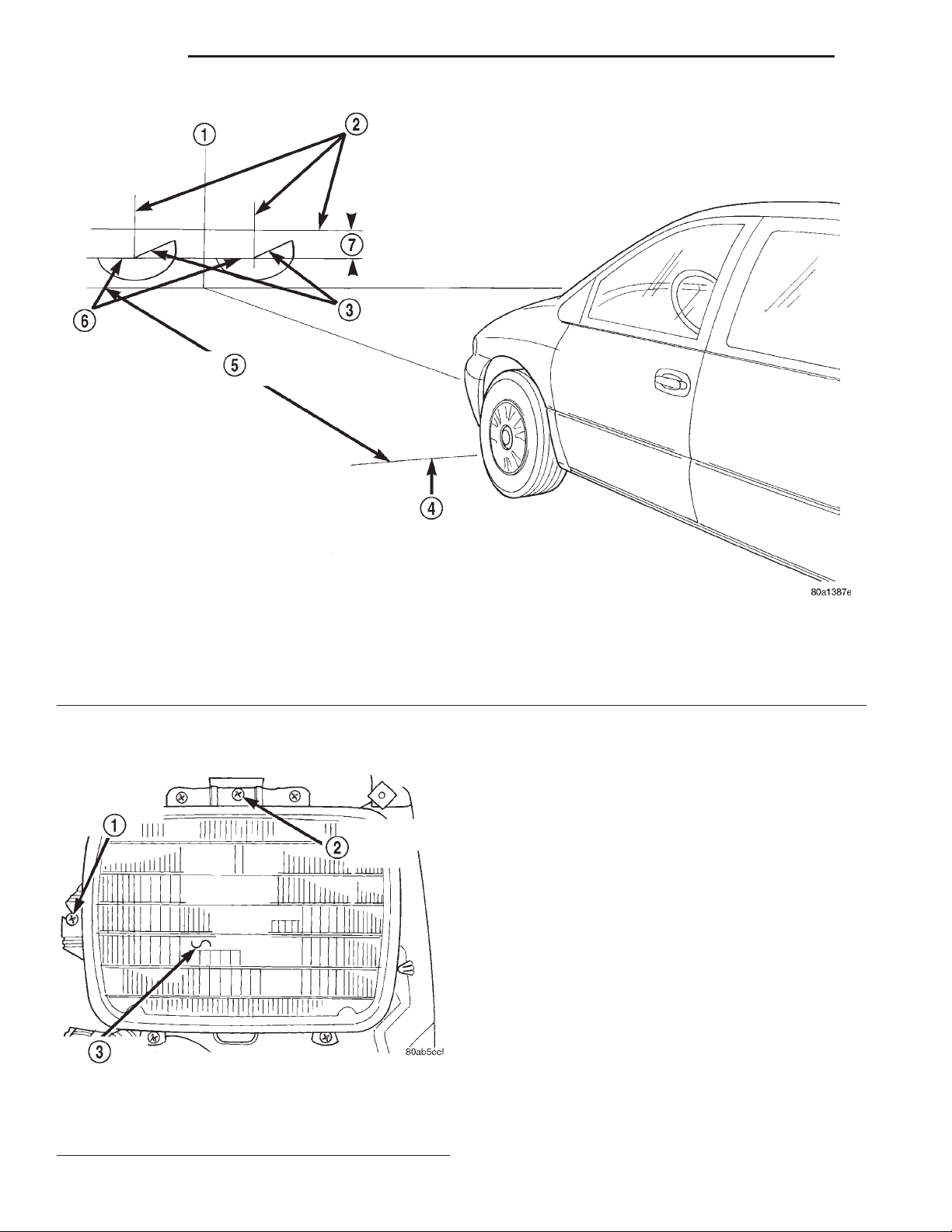
(1) Position vehicle on a level surface perpendicular to a flat wall 10 meters (32.8 ft.) away from front
of headlamp lens (Fig. 1).
(2) Place 75 kg in the driver’s seat to simulate the
ride height of the vehicle when driven.
(3) If necessary, tape a line on the floor 10 meters
(32.8 ft) away from and parallel to the wall.
(4) From the floor up 1.27 meters (5 ft), tape a line
on the wall at the centerline of the vehicle. Sight
along the centerline of the vehicle (from rear of vehicle forward) to verify accuracy of the line placement.
ADJUSTMENTS
HEADLAMP/FOG LAMPADJUSTMENT USING
ALIGNMENT SCREEN ....................3
(5) Rock vehicle side-to-side three times and allow
suspension to stabilize.
(6) Jounce front suspension three times by pushing
downward on front bumper and releasing.
(7) Measure the distance from the center of headlamp lens to the floor. Transfer measurement to the
alignment screen (with tape). Use this line for
up/down adjustment reference.
(8) Place a tape line 130 mm below and parallel to
the center of headlamp line.
(9) Measure distance from the centerline of the
vehicle to the center of each headlamp being aligned.
Transfer measurements to screen (with tape) to each
side of vehicle centerline. Use these lines for left/
right adjustment reference.
HEADLAMP ADJUSTMENT
A properly aimed low beam headlamp will project a
high intensity light pattern on the screen with the
horizontal cut-off line aligned with the tape line 130
mm (5.12 in.) below the headlamp centerline (Fig. 1).
The intersection of the horizontal and 15 degree cutoff lines in the projected pattern should align to the
intersection of the headlamp centerline vertical tape
line and the tape line 130 mm (5.12 in.) below the
headlamp horizontal centerline. The high beams on a
vehicle with aero headlamps cannot be aligned. The
high beam pattern should be correct when the low
beams are aligned properly.
To adjust headlamp alignment, rotate alignment
screws (Fig. 2) to achieve the specified low beam hot
spot pattern.
Page 4
8L - 4 LAMPS XJ
ADJUSTMENTS (Continued)
1 – CENTER OF VEHICLE
2 – CENTER OF HEADLAMPS
3 – 15° CUT-OFF LINE
4 – FRONT OF HEADLAMP
Fig. 1 Headlamp Alignment Screen—Typical
5 – 10 METERS (32.8 ft.)
6 – HORIZONTAL CUT-OFF LINE
7 – 130mm
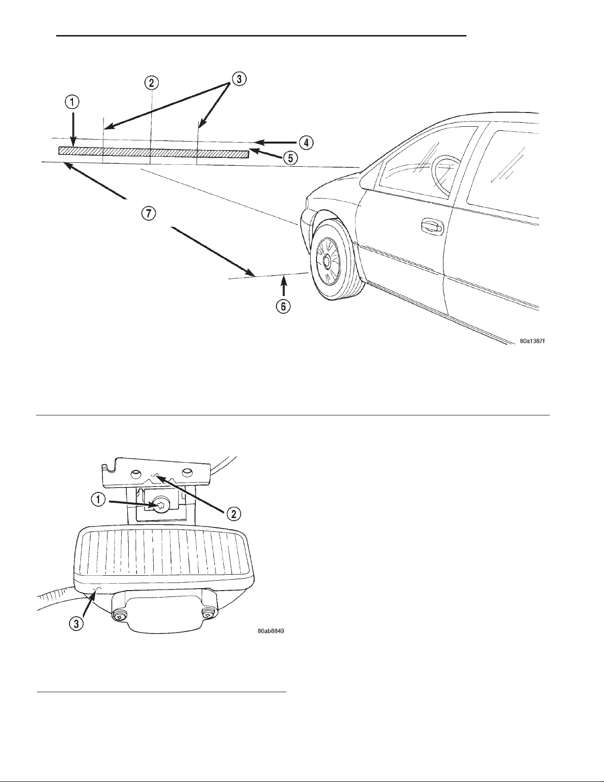
FOG LAMP ALIGNMENT
Prepare an alignment screen. Refer to the Alignment Screen Preparation paragraph in this section. A
properly aligned fog lamp will project a pattern on
the alignment screen 200 mm (8 in.) below the fog
lamp centerline and straight ahead (Fig. 3). To
improve visual interpretation of the fog lamp pattern
on the alignment screen, disable the headlamps by
disengaging the wire connectors from the headlamp
bulbs.
To adjust fog lamp alignment, rotate alignment
screws (Fig. 4) to achieve the specified pattern.
Fig. 2 Headlamp Beam Adustment Screws
1 – LEFT/RIGHTADJUSTMENT SCREW
2 – UP/DOWN ADJUSTMENT SCREW
3 – HEADLAMP
Page 5
XJ LAMPS 8L - 5
ADJUSTMENTS (Continued)
1 – HIGH INTENSITY AREA
2 – CENTER OF VEHICLE
3 – VERTICAL CENTER OF FOG LAMP
4 – HORIZONTAL CENTER OF FOG LAMP
Fig. 3 Fog Lamp Alignment-Typical
5 – 200mm (8 in.)
6 – FRONT OF FOG LAMP
7 – 10 METERS (32.8 ft.)
Fig. 4 Fog Lamp Beam Adjustment Screws
1 – ADJUSTMENT SCREW
2 – MOUNTING BRACKET
3 – FOG LAMP
Page 6
8L - 6 LAMPS XJ
LAMP BULB SERVICE
TABLE OF CONTENTS
page page
REMOVAL AND INSTALLATION
FRONT POSITION LAMP BULB ...............6
SIDE REPEATER LAMP BULB ................6
REMOVAL AND INSTALLATION
FRONT POSITION LAMP BULB
REMOVAL
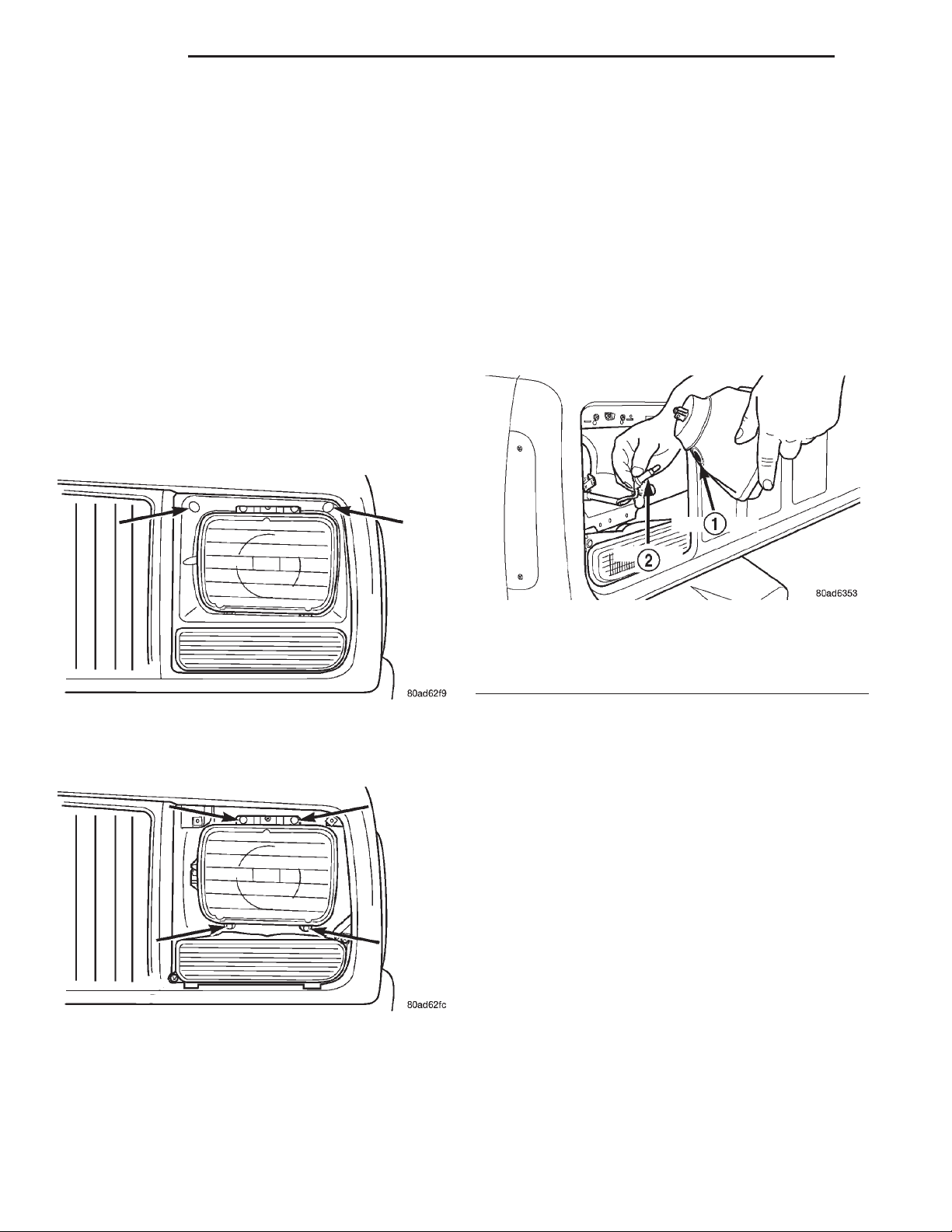
(1) Remove the 2 screws holding the headlamp
bezel in place and remove bezel (Fig. 1).
REAR FOG LAMP BULB ....................7
LICENSE PLATE LAMP BULB ................7
(3) Pull the front position lamp straight from
headlamp (Fig. 3).
Fig. 3 Front Position Lamp Grommet & Socket
Location
1 – GROMMET
2 – SOCKET
Fig. 1 Headlight Bezel Retaining Screws
(2) Remove the 4 screws holding the headlamp
(Fig. 2).
Fig. 2 Headlamp Retaining Screws
(4) Remove the front position lamp bulb from
socket.
INSTALLATION
(1) Install the front position lamp bulb in lamp
socket.
(2) Verify lamp operation.
(3) Install front position lamp in headlamp.
(4) Connect headlamp electrical connector.
(5) Position the headlamp, headlamp retaining
ring and install the retaining screws.
(6) Position the headlamp bezel and install retaining screws.
SIDE REPEATER LAMP BULB
REMOVAL
(1) Grip the side repeater lamp assembly and pull
straight from the fender.
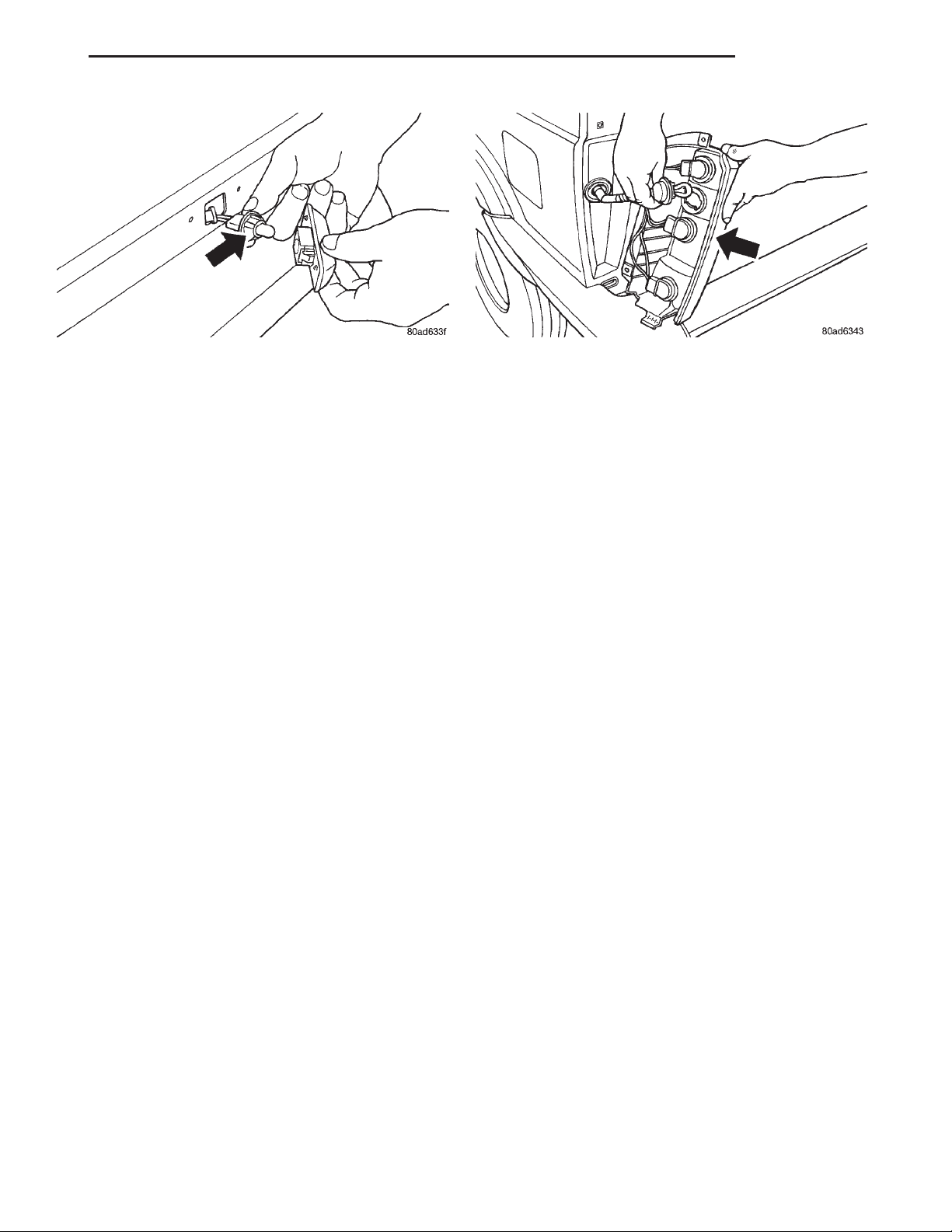
(2) Rotate and pull the socket from the housing
(Fig. 4).
(3) Pull the bulb straight from the socket.
Page 7
XJ LAMPS 8L - 7
REMOVAL AND INSTALLATION (Continued)
Fig. 4 Side Repeater Lamp Fig. 5 Rear Lamp Replacement
INSTALLATION
(1) Align the side repeater lamp bulb to the socket
(Fig. 4).
(2) Push the bulb into the socket.
(3) Verify lamp operation.
(4) Push and rotate the socket into the housing.
(5) Press the lamp assembly into the fender
mounting hole.
REAR FOG LAMP BULB
REMOVAL
(1) There are 3 mounting bolts attaching the taillight assembly. When removing, unfasten the 3 bolts
located on the top and side. Lift up and out to
remove the assembly.
(2) Turn the socket assembly 1/3 turn and pull the
socket from the housing (Fig. 5).
(3) Pull the rear fog lamp straight from its socket.
INSTALLATION
(1) Install rear fog lamp bulb in its socket.
(2) Verify lamp operation.
(3) Install the remaining three lamp sockets in the
taillamp assembly.
(4) Position the taillamp assembly and install the
retaining screws.
LICENSE PLATE LAMP BULB
REMOVAL
(1) Remove the appropriate license plate lamp
retaining screws.
(2) Pull lamp housing from rear liftgate. Lamp
must be positioned properly to allow removal without
removing license plate.
(3) Rotate the lamp socket counter clockwise and
pull straight from lamp housing.
(4) Pull the lamp bulb straight from its socket.
INSTALLATION
(1) Install bulb in lamp socket.
(2) Verify lamp operation.
(3) Install lamp socket in lamp housing.
(4) Install license plate lamp assembly in liftgate
and install retaining screws.
Page 8
8L - 8 LAMPS XJ
LAMP SERVICE
TABLE OF CONTENTS
page page
REMOVAL AND INSTALLATION
HEADLAMP ..............................8
HEADLAMP LEVELING MOTOR...............8
SIDE REPEATER LAMP.....................9
REMOVAL AND INSTALLATION
HEADLAMP
REMOVAL
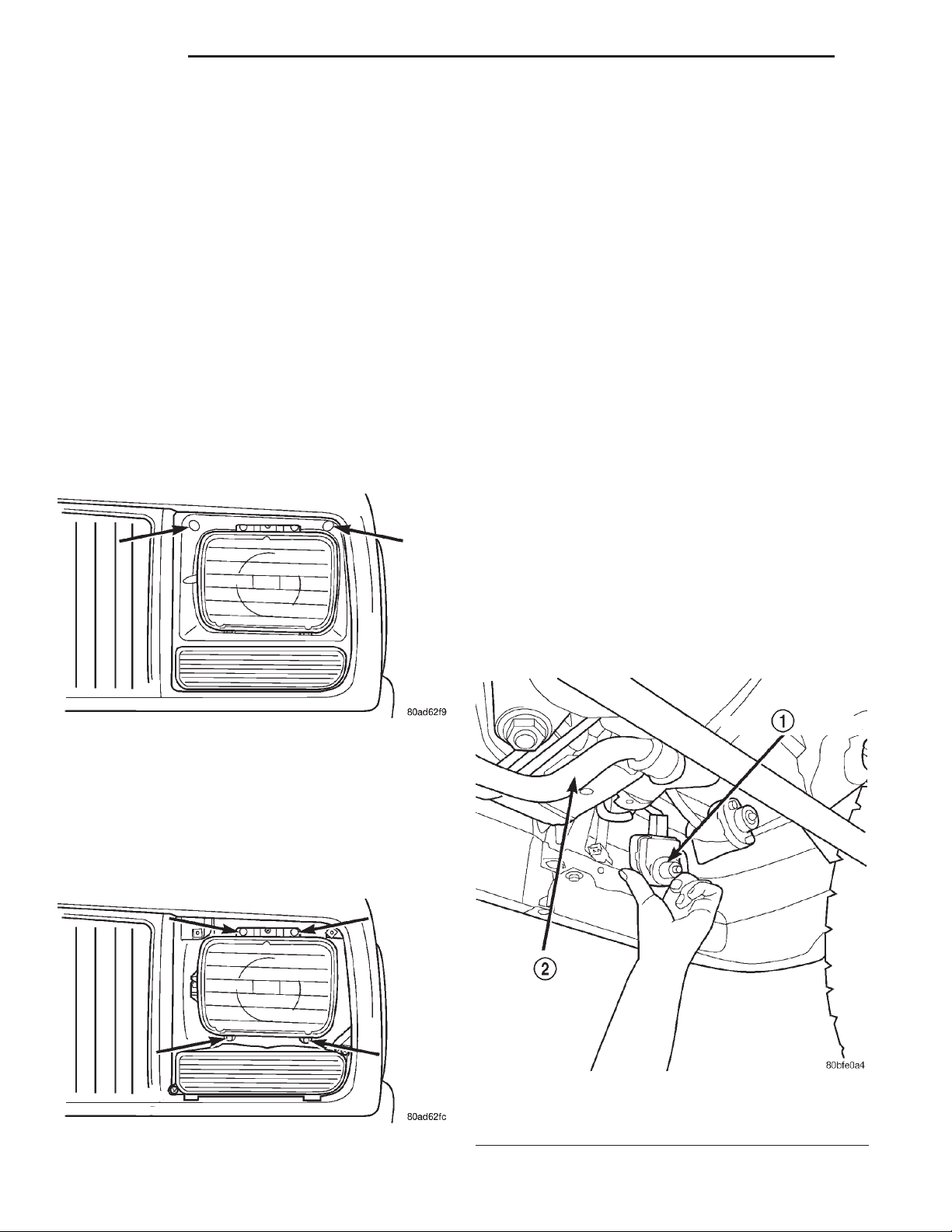
(1) Remove the 2 screws holding the headlamp
bezel in place and remove bezel (Fig. 1).
FRONT FOG LAMP ........................9
REAR TURN SIGNAL, BACKUP, TAILLAMP
AND FOG LAMP .........................9
LICENSE PLATE LAMP .....................9
INSTALLATION
(1) Install front position lamp in headlamp.
(2) Connect headlamp electrical connector.
(3) Position the headlamp, headlamp retaining
ring and install the retaining screws.
(4) Position the headlamp bezel and install retaining screws.
HEADLAMP LEVELING MOTOR
REMOVAL
(1) Open the hood and disconnect the negative battery cable.
(2) Raise the vehicle on a hoist or position a
creeper under the front of the vehicle.
(3) Remove the appropriate side front splash
shield. Located just in front of the front wheel.
Fig. 1 Headlight Bezel Retaining Screws
(2) Remove the 4 screws holding the headlamp
(Fig. 2).
(3) Pull the front position lamp straight from
headlamp.
(4) Disconnect the headlamp electrical connector
by pulling straight off.
(5) Remove the headlamp from the vehicle.
Fig. 2 Headlamp Retaining Screws
Fig. 3 Headlamp Leveling Motor
1 – HEADLAMP LEVELING MOTOR
2 – FRONT STABILIZER BAR
Page 9
XJ LAMPS 8L - 9
REMOVAL AND INSTALLATION (Continued)
(4) Disconnect the headlamp leveling motor electri-
cal connector.
(5) Rotate the leveling motor 90 degrees until
motor is loose in mounting bracket.
(6) Tilt motor upwards to disconnect motor push
rod from the headlamp leveling linkage.
(7) Remove the headlamp leveling motor from the
vehicle (Fig. 3).
INSTALLATION
(1) Install leveling motor push rod through hole in
mounting bracket and connect push rod on leveling
linkage. The proper angle must be achieved to connect the push rod onto the leveling linkage.
(2) Once the push rod is connected, rotate motor
until tabs line up with tabs in mounting bracket.
Once the tabs are lined up push and rotate the motor
90 degrees to lock in place.
(3) Connect the headlamp leveling motor electrical
connector.
(4) Position the front splash shield.
(5) Lower the vehicle and connect the negative
battery cable.
SIDE REPEATER LAMP
FRONT FOG LAMP
REMOVAL
1. Remove the 2 screws from the bottom cover of
the lamp body.
2. Disconnect the 2 wires from the lamp element.
3. Remove the lamp element from the housing.
INSTALLATION
1. Install the new lamp element in the housing
and reinstall the lower housing.
REAR TURN SIGNAL, BACKUP, TAILLAMP AND FOG LAMP
REMOVAL
(1) There are 3 mounting bolts attaching the taillight assembly. When removing, unfasten the 3 bolts
located on the top and side. Lift up and out to
remove the assembly.
REMOVAL
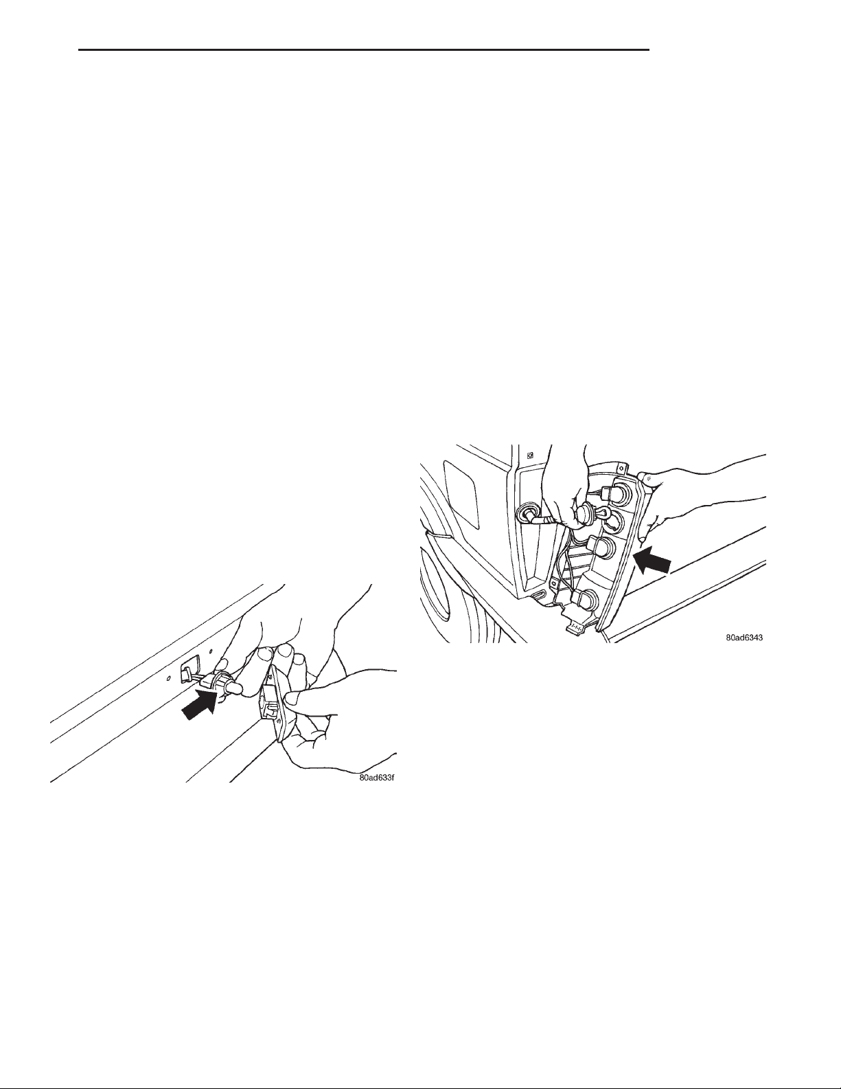
(1) Grip the side repeater lamp assembly and pull
straight from the fender.
Fig. 4 Side Repeater Lamp
(2) Rotate and pull the socket from the housing
(Fig. 4).
INSTALLATION
(1) Push and rotate the socket into the housing.
(2) Verify lamp operation.
(3) Press the lamp assembly into the fender
mounting hole.
Fig. 5 Rear Lamp Replacement
(2) Turn the socket assembly 1/3 turn and pull the
socket from the housing (Fig. 5).
INSTALLATION
(1) Install the four lamp sockets in the taillamp
assembly.
(2) Verify lamp operation.
(3) Position the taillamp assembly and install the
retaining screws.
LICENSE PLATE LAMP
REMOVAL
(1) Remove the appropriate license plate lamp
retaining screws.
(2) Pull lamp housing from rear liftgate. Lamp
must be positioned properly to allow removal without
removing license plate.
(3) Rotate the lamp socket counter clockwise and
pull straight from lamp housing.
Page 10

8L - 10 LAMPS XJ
REMOVAL AND INSTALLATION (Continued)
INSTALLATION
(1) Install lamp socket in lamp housing.
(2) Verify lamp operation.
(3) Install license plate lamp assembly in liftgate
and install retaining screws.
Page 11

XJ LAMPS 8L - 11
BULB APPLICATION
TABLE OF CONTENTS
page
SPECIFICATIONS
REPLACEMENT BULBS ....................11
SPECIFICATIONS
REPLACEMENT BULBS
Exterior Lamps Bulb Type
Headlamp ............................. H4
Front Position ......................... T4W
Front Turn Signal .................... P27/7W
Side Turn Signal ...................... W3W
License Lamp ......................... W5W
Rear Position and Stop ................ P27/7W
Rear Turn Signal .................... P27/7W
Reversing .......................... P27/7W
Rear Fog ........................... P27/7W
Underhood Lamp ...................... W5W
Underhood Retractable Lamp .............. 105
Front Fog .............................. H3
CHMSL ............................ W16W
Interior Lamps Bulb Type
Ashtray Lamp ......................... 1891
Cigarette Lighter Lamp ................... 53
Auto. Trans. Floor Shift Lamp ............. 658
Cargo Lamp ........................... 561
Climate Control Lamp (2) .................. 74
Dome Lamp ........................... 561
Dome/Reading Lamp ......... (1)561and(2)906
Glove Box Lamp ........................ 194
Lighted Vanity Mirror (2) .................. 74
Map Reading Light in Overhead Console (4) . . . 912
Rocker Switch ........................... 37
Transfer Case Lamp ..................... 658
Underpanel Courtesy lamps (2) ............ 168
NOTE: Numbers refer to commercial bulb types
that can be purchased from your local Jeep dealer.
Page 12

 Loading...