

Page 1
XJ WIPER AND WASHER SYSTEMS 8K - 1
WIPER AND WASHER SYSTEMS
TABLE OF CONTENTS
page page
GENERAL INFORMATION
INTRODUCTION ..........................1
WINDSHIELD WIPER SYSTEM ..............1
WINDSHIELD WASHER SYSTEM.............1
REAR WIPER AND WASHER SYSTEM ........2
DESCRIPTION AND OPERATION
WIPER ARM AND BLADE...................2
WIPER LINKAGE AND PIVOT................2
WIPER MOTOR...........................2
WIPER SWITCH AND WASHER SWITCH.......3
WASHER RESERVOIR .....................3
WASHER PUMP ..........................4
WASHER FLUID LEVEL SENSOR.............4
GENERAL INFORMATION
INTRODUCTION
Windshield wiper and washer systems are standard factory-installed equipment on this model. A
rear wiper and washer system is optional factory-installed equipment. Following is general information
about the available wiper and washer systems for
this vehicle. Refer to 8W-53 - Wipers in Group 8W Wiring Diagrams for complete circuit descriptions
and diagrams.
NOTE: This group covers both Left-Hand Drive
(LHD) and Right-Hand Drive (RHD) versions of this
model. Whenever required and feasible, the RHD
versions of affected vehicle components have been
constructed as mirror-image of the LHD versions.
While most of the illustrations used in this group
represent only the LHD version, the diagnostic and
service procedures outlined can generally be
applied to either version. Exceptions to this rule
have been clearly identified as LHD or RHD, if a
special illustration or procedure is required.
WINDSHIELD WIPER SYSTEM
An intermittent windshield wiper system is standard equipment on this model. The intermittent
wiper system lets the driver select from either of two
wiper speeds, low or high, or the intermittent wipe
delay mode.
WASHER NOZZLE AND PLUMBING...........4
DIAGNOSIS AND TESTING
WIPER SYSTEM..........................4
WASHER SYSTEM ........................6
WIPER SWITCH AND WASHER SWITCH.......7
REMOVAL AND INSTALLATION
WIPER BLADE ...........................8
WIPER ARM.............................8
WIPER LINKAGE AND PIVOT................9
WIPER MOTOR...........................9
WIPER SWITCH AND WASHER SWITCH......11
WASHER SYSTEM .......................13
The intermittent wipe mode delay times are driver
adjustable from about one second to about fifteen seconds. The intermittent wipe mode is provided by
delay logic and relay control circuitry contained
within the intermittent wiper/washer switch. The
intermittent wipe relay is also contained within the
switch.
The windshield wipers will operate only when the
ignition switch is in the Accessory or On positions. A
circuit breaker located in the junction block protects
the circuitry of the windshield wiper system. Refer to
the owner’s manual in the vehicle glove box for more
information on the features, use and operation of the
windshield wiper system.
WINDSHIELD WASHER SYSTEM
An electrically operated windshield washer system
is standard equipment. The washer reservoir is
located between the inner and outer front fenders,
above and forward of the left front wheel housing.
The reservoir filler neck is located in the engine compartment on the left inner fender shield.
The washer reservoir holds the washer fluid, which
is pressurized by a pump when the windshield
washer switch lever is actuated. The windshield
washer pump feeds the pressurized washer fluid
through the washer system plumbing to the windshield washer nozzles.
A low washer fluid warning lamp is standard
equipment on all models equipped with the optional
rear wiper and washer system. The low washer fluid
warning lamp in the instrument cluster will warn
Page 2

8K - 2 WIPER AND WASHER SYSTEMS XJ
GENERAL INFORMATION (Continued)
the driver when the washer fluid level needs to be
checked. Refer to Group 8E - Instrument Panel Systems for more information on this feature.
The washers will operate only when the ignition
switch is in the Accessory or On positions. If the wipers are not already turned on when the washers are
activated, the wipers will be automatically cycled for
one or two wipes, then be turned off. A fuse located
in the junction block protects the circuitry of the
washer system. Refer to the owner’s manual in the
vehicle glove box for more information on the features, use and operation of the windshield washer
system.
REAR WIPER AND WASHER SYSTEM
A rear wiper and washer system is an available
option on this model. The rear wiper system is a
fixed-cycle wiper system. A single switch in the
instrument panel accessory switch bezel controls both
the rear wiper and washer functions. The rear
washer system shares the reservoir of the windshield
washer system, but has its own dedicated washer
pump and plumbing.
The rear wiper and washer systems will operate
only when the ignition switch is in the Accessory or
On positions. A fuse in the junction block protects the
circuitry of both the rear wiper and washer systems.
Refer to the owner’s manual in the vehicle glove
box for more information on the features, use and
operation of the rear wiper and washer system.
DESCRIPTION AND OPERATION
WIPER ARM AND BLADE
All Cherokee models have two 45.72-centimeter
(18-inch) windshield wiper blades with non-replaceable rubber elements (squeegees). The optional rear
wiper uses a single 33.0-centimeter (13-inch) wiper
blade with a non-replaceable rubber element (squeegee).
Caution should be exercised to protect the rubber
squeegees from any petroleum-based cleaners or contaminants, which will rapidly deteriorate the rubber.
If the squeegees are damaged, worn, or contaminated, the entire wiper blade assembly must be
replaced.
Wiper squeegees exposed to the elements for a long
time tend to lose their wiping effectiveness. Periodic
cleaning of the squeegees is suggested to remove
deposits of salt and road film. The wiper blades,
arms, and windshield or rear glass should be cleaned
with a sponge or cloth and windshield washer fluid, a
mild detergent, or a non-abrasive cleaner. If the
squeegees continue to streak or smear, the wiper
blades should be replaced.
The blades are mounted to spring-loaded wiper
arms. The spring tension of the wiper arms controls
the pressure applied to the blades on the glass. The
windshield wiper arms are secured by an integral
latch to the two wiper pivots on the cowl plenum cover/grille panel at the base of the windshield. The rear
wiper arm is secured by a nut directly to the rear
wiper motor output shaft on the liftgate below the
liftgate glass.
The wiper arms and blades cannot be adjusted or
repaired. If faulty or damaged, they must be
replaced.
WIPER LINKAGE AND PIVOT
The wiper linkage and pivot module is secured
with screws to the cowl top panel beneath the cowl
plenum cover/grille panel. The wiper motor is
secured with screws to the center of the linkage and
pivot module bracket. The wiper pivots are secured
to the ends of the module bracket.
The two wiper pivot crank arms and the wiper
motor crank arm each have ball studs on their ends.
The left pivot ball stud is the longer of the three. A
connecting link with a plastic socket-type bushing in
the right end, and a plastic sleeve-type bushing in
the left end, is fit over the pivot ball studs to join the
two pivots.
The wiper drive link has a plastic socket-type
bushing on each end. One end of the drive link is
snap-fit over the exposed end of the longer left pivot
ball stud, while the other end is snap-fit over the ball
stud on the wiper motor crank arm.
The wiper linkage, pivots, bushings, motor, crank
arm, and mounting bracket are only serviced as a
complete unit. If any part of this assembly is faulty
or damaged, the entire unit must be replaced.
WIPER MOTOR
FRONT
The two-speed permanent magnet wiper motor has
an integral transmission and park switch. The motor
also contains an internal automatic resetting circuit
breaker to protect the motor from overloads.
The motor is secured to the wiper linkage and
pivot module bracket with three screws and is protected by a rubber boot. The wiper motor output
shaft passes through a hole in the module bracket,
where a nut secures the wiper motor crank arm to
the motor output shaft. A reinforcement and stud
plate with a rubber-isolated mounting bracket
extends from the cowl plenum side of the dash panel
to the motor mounting bracket to provide additional
support.
Wiper speed is controlled by current flow to the
proper set of brushes. The wiper motor completes its
Page 3
XJ WIPER AND WASHER SYSTEMS 8K - 3
DESCRIPTION AND OPERATION (Continued)
wipe cycle when the windshield wiper switch stalk is
moved to the Off position, and parks the blades in
the lowest portion of the wipe pattern.
The windshield wiper motor cannot be repaired. If
faulty or damaged, the entire wiper linkage and pivot
module unit must be replaced. The reinforcement
bracket and stud plate are available for service.
REAR
The rear wiper motor is secured to a bracket that
is fastened to the liftgate inner panel, below the liftgate glass and behind the liftgate trim panel. The
motor output shaft passes through the liftgate outer
panel where a rubber gasket and plastic bezel unit,
and a nut seal and secure the unit to the liftgate
outer panel. The rear wiper arm is secured directly
to the motor output shaft with a nut.
The rear wiper motor unit provides three operating
modes:
• Constant wipe that operates when the rear
wiper switch is turned to the On position.
• Constant wipe that operates when the rear
washer switch is depressed.
• A park mode that operates the wiper motor until
the blade reaches its park position when either the
rear wiper switch or the ignition switch is placed in
the Off position.
The rear wiper motor cannot be repaired. If faulty
or damaged, the entire rear wiper motor assembly
must be replaced.
WIPER SWITCH AND WASHER SWITCH
FRONT
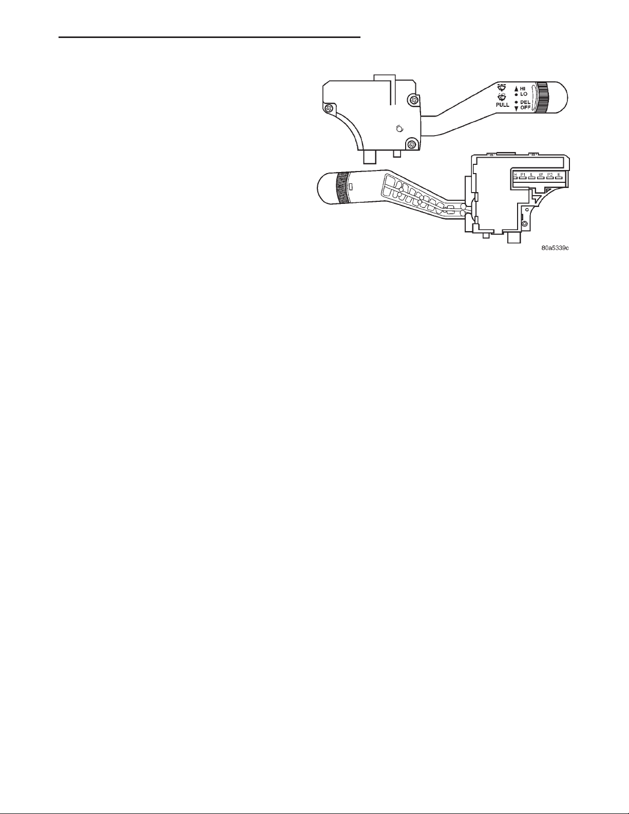
The windshield wiper and washer switches are
mounted on the right side of the steering column
(Fig. 1). The switch stalk is moved up or down to
select the wiper switch mode, and pulled towards the
steering wheel to activate the washer system. An
intermittent wipe system control knob on the end of
the switch stalk is rotated to select the desired delay
interval. The windshield wiper and washer switch
contains circuitry for the following functions:
• Windshield wipers
• Intermittent wiper delay relay control and logic
• Intermittent wipe relay
• Windshield washers.
The windshield wiper and washer switch cannot be
repaired. If any function of the switch is faulty, or if
the switch is damaged, the entire switch unit must
be replaced.
REAR
The single two-function rear wiper and washer
switch is installed in the instrument panel accessory
switch bezel, which is located near the bottom of the
Fig. 1 Windshield Wiper Switch and Washer Switch
instrument panel center bezel area, below the heater
and air conditioner controls. The rear wiper and
washer switch controls the rear wiper and washer
functions.
The toggle-type switch features a detent in the On
position, and a momentary Wash position. The rear
wiper and washer switch also has an integral illumination lamp with a serviceable bulb. The switch knob
is pushed down to its detent to activate the rear
wiper system, and down again to the momentary
position to activate the rear washer system. Both the
rear wiper and rear washer motors will operate continuously for as long as the switch is held in the
momentary Wash position.
The rear wiper and washer switch cannot be
repaired and, if faulty or damaged, the entire switch
unit must be replaced.
WASHER RESERVOIR
A single washer fluid reservoir is used for both the
standard front and optional rear washer systems.
The washer fluid reservoir is secured between the
left front inner and outer fender panels, above and in
front of the left front wheel house.
Each washer pump and motor unit has a barbed
nipple, which is installed through a rubber grommet
seal inserted in a hole near the bottom of the reservoir. The washer pumps are retained by an interference fit between the barbed nipple and the grommet
seal, which is a light press fit.
The washer reservoir has a separate filler neck
and grommet seal. The filler neck snaps into the reservoir from the engine compartment side of the left
inner fender shield. A snap-fit filler cap with an integral bail strap is fit to the reservoir filler neck. On
models so equipped, the reservoir also has a hole provided for a washer fluid level sensor.
The washer reservoir, filler neck, grommet seal,
and filler cap are each available for service.
Page 4

8K - 4 WIPER AND WASHER SYSTEMS XJ
DESCRIPTION AND OPERATION (Continued)
WASHER PUMP
The washer pumps and motors are mounted near
the bottom of the washer reservoir. A barbed nipple
on the pump housing passes through a rubber grommet seal installed in a hole near the bottom of the
reservoir. The washer pump is retained by an interference fit between the barbed pump nipple and the
grommet seal, which is a light press fit.
A permanently lubricated and sealed motor is coupled to a rotor-type pump. Washer fluid is gravity-fed
from the reservoir to the pump. When the motor is
energized, the pump pressurizes the washer fluid
and forces it through the plumbing to the nozzles.
On vehicles with the optional rear wiper/washer
system, the front washer pump and motor is always
mounted in the lower hole of the reservoir. The
washer pump and motor unit cannot be repaired. If
faulty, the entire washer pump and motor unit must
be replaced.
WASHER FLUID LEVEL SENSOR
The washer fluid level sensor is mounted near the
front of the washer reservoir, above the two washer
pumps. A barbed nipple on the sensor is press-fit into
a rubber grommet seal installed in a hole in the front
of the reservoir.
When the fluid level in the reservoir falls below
the pivoting float on the sensor, the float changes
position and closes the internal switch contacts of the
sensor. Refer to Group 8E - Instrument Panel Systems for diagnosis of the low washer fluid warning
lamp and circuit, including the sensor.
The washer fluid level sensor cannot be repaired. If
faulty or damaged, the sensor unit must be replaced.
WASHER NOZZLE AND PLUMBING
FRONT
Pressurized washer fluid is fed through a single
hose, attached to a barbed nipple on the front washer
pump. The hose is routed to a tee fitting located in
the cowl plenum area, beneath the cowl plenum cover/grille panel. Hoses from the tee fitting are routed
to the two nozzles, which are riveted into openings in
the cowl plenum cover/grille panel below the windshield.
The two fluidic washer nozzles are not adjustable.
The nozzles and hose fittings cannot be repaired and,
if faulty or damaged, they must be replaced.
REAR
Pressurized washer fluid is fed through a single
hose, attached to a barbed nipple on the rear washer
pump. The hose is routed from the front of the vehicle to the liftgate with the body wire harness.
Located at the highest point of the supply hose
routing, beneath the liftgate opening upper header
garnish moulding, the hose connects to a check valve.
The check valve prevents washer fluid drain-back or
siphoning from occurring. From the check valve,
another single hose is routed through a grommet to
the liftgate, where it is connected to a nipple that
protrudes from the inside of the rear wiper motor
output shaft bezel.
The washer fluid passes through the bezel nipple
to the outside of the liftgate. There a single hose is
connected to a nipple on the outside of the rear wiper
motor output shaft bezel. The hose is routed through
a plastic trough-like guard snapped to the underside
of the rear wiper arm. The hose is then attached to
the single rear washer nozzle. The nozzle snaps into
place on the rear wiper arm.
The rear washer nozzle cannot be adjusted. The
nozzle, bezel, check valve, and hose fittings cannot be
repaired and, if faulty or damaged, they must be
replaced.
DIAGNOSIS AND TESTING
WIPER SYSTEM
FRONT
For circuit descriptions and diagrams, refer to
8W-53 - Wipers in Group 8W - Wiring Diagrams.
WARNING: ON VEHICLES EQUIPPED WITH AIRBAGS, REFER TO GROUP 8M - PASSIVE
RESTRAINT SYSTEMS BEFORE ATTEMPTING ANY
STEERING WHEEL, STEERING COLUMN, OR
INSTRUMENT PANEL COMPONENT DIAGNOSIS OR
SERVICE. FAILURE TO TAKE THE PROPER PRECAUTIONS COULD RESULT IN ACCIDENTAL AIRBAG DEPLOYMENT AND POSSIBLE PERSONAL
INJURY.
(1) Check the circuit breaker in the junction block.
If OK, go to Step 2. If not OK, replace the faulty circuit breaker.
(2) Disconnect and isolate the battery negative
cable. Unplug the windshield wiper switch wire harness connector. Connect the battery negative cable.
Turn the ignition switch to the On position. Check
for battery voltage at the fused ignition switch output (run/acc) circuit cavity of the wiper switch wire
harness connector. If OK, go to Step 3. If not OK,
repair the open circuit to the junction block as
required.
(3) If the problem being diagnosed involves only
the pulse wipe, wipe-after-wash, or intermittent wipe
modes, go to Step 4. If not, go to Step 5.
Page 5

XJ WIPER AND WASHER SYSTEMS 8K - 5
DIAGNOSIS AND TESTING (Continued)
(4) Turn the ignition switch to the Off position.
Disconnect and isolate the battery negative cable.
Check for continuity between the ground circuit cavity of the wiper switch wire harness connector and a
good ground. There should be continuity. If OK,
replace the faulty switch. If not OK, repair the open
circuit to ground as required.
(5) Turn the ignition switch to the Off position.
Disconnect and isolate the battery negative cable.
Remove the windshield wiper and washer switch and
check the switch continuity. See Wiper Switch and
Washer Switch in the Diagnosis and Testing section
of this group for the procedures. If OK, go to Step 6.
If not OK, replace the faulty switch.
(6) Unplug the windshield wiper motor wire harness connector. Check for continuity between the
ground circuit cavity in the body half of the wiper
motor wire harness connector and a good ground.
There should be continuity. If OK, go to Step 7. If not
OK, repair the open circuit to ground as required.
(7) Connect the battery negative cable. Turn the
ignition switch to the On position. Check for battery
voltage at the fused ignition switch output (run/acc)
circuit cavity in the body half of the wiper motor wire
harness connector. If OK, go to Step 8. If not OK,
repair the open circuit to the junction block as
required.
(8) Turn the ignition switch to the Off position.
Disconnect and isolate the battery negative cable.
With the windshield wiper and washer switch wire
harness connector still unplugged, check the cavities
for each of the following circuits in the body half of
the wiper motor wire harness connector for continuity to ground. In each case, there should be no continuity. If OK, go to Step 9. If not OK, repair the short
circuit as required.
• Wiper park switch sense
• Wiper switch low speed output
• Wiper switch high speed output.
(9) Check for continuity between the cavities in
the body half of the wiper motor wire harness connector and the cavities in the windshield wiper and
washer switch wire harness connector for each of the
following circuits. In each case, there should be continuity. If OK, replace the faulty wiper motor. If not
OK, repair the open circuit as required.
• Wiper park switch sense
• Wiper switch low speed output
• Wiper switch high speed output.
REAR
For circuit descriptions and diagrams, refer to
8W-53 - Wipers in Group 8W - Wiring Diagrams.
WARNING: ON VEHICLES EQUIPPED WITH AIRBAGS, REFER TO GROUP 8M - PASSIVE
RESTRAINT SYSTEMS BEFORE ATTEMPTING ANY
STEERING WHEEL, STEERING COLUMN, OR
INSTRUMENT PANEL COMPONENT DIAGNOSIS OR
SERVICE. FAILURE TO TAKE THE PROPER PRECAUTIONS COULD RESULT IN ACCIDENTAL AIRBAG DEPLOYMENT AND POSSIBLE PERSONAL
INJURY.
(1) Check the fuse in the junction block. If OK, go
to Step 2. If not OK, repair the shorted circuit or
component as required and replace the faulty fuse.
(2) Disconnect and isolate the battery negative
cable. Remove the accessory switch bezel and unplug
the wire harness connector from the rear wiper and
washer switch. Connect the battery negative cable.
Turn the ignition switch to the On position. Check
for battery voltage at the fused ignition switch output circuit cavity of the rear wiper and washer
switch wire harness connector. If OK, go to Step 3. If
not OK, repair the open circuit to the junction block
as required.
(3) Turn the ignition switch to the Off position.
Disconnect and isolate the battery negative cable.
Check for continuity between the ground circuit cavity of the rear wiper and washer switch wire harness
connector and a good ground. There should be continuity. If OK, go to Step 4. If not OK, repair the open
circuit to ground as required.
(4) Test the rear wiper and washer switch continuity. See Wiper Switch and Washer Switch in the
Diagnosis and Testing section of this group for the
procedures. If OK, go to Step 5. If not OK, replace
the faulty switch.
(5) Remove the liftgate trim panel and unplug the
rear wiper motor wire harness connector. Connect
the battery negative cable. Turn the ignition switch
to the On position. Check for battery voltage at the
fused ignition switch output (run) circuit cavity of
the rear wiper motor wire harness connector. If OK,
go to Step 6. If not OK, repair the open circuit to the
junction block as required.
(6) Turn the ignition switch to the Off position.
Disconnect and isolate the battery negative cable.
Check for continuity between the ground circuit cavity of the rear wiper motor wire harness connector
and a good ground. There should be continuity. If
OK, go to Step 7. If not OK, repair the open circuit to
ground as required.
(7) Check for continuity between the rear wiper
motor control circuit cavity of the rear wiper motor
wire harness connector and a good ground. There
should be no continuity. If OK, go to Step 8. If not
OK, repair the short circuit as required.
(8) Check for continuity between the rear wiper
motor control circuit cavities of the rear wiper motor
wire harness connector and the rear wiper and
washer switch wire harness connector. There should
Page 6

8K - 6 WIPER AND WASHER SYSTEMS XJ
DIAGNOSIS AND TESTING (Continued)
be continuity. If OK, replace the faulty rear wiper
motor. If not OK, repair the open circuit as required.
WASHER SYSTEM
FRONT
The diagnosis found here addresses an inoperative
front washer pump. If the washer pump operates,
but no washer fluid is emitted from the washer nozzles, be certain to check the fluid level in the reservoir. Check for ice or other foreign material in the
reservoir, and for pinched, disconnected, broken, or
incorrectly routed washer system plumbing. For circuit descriptions and diagrams, refer to 8W-53 - Wipers in Group 8W - Wiring Diagrams.
WARNING: ON VEHICLES EQUIPPED WITH AIRBAGS, REFER TO GROUP 8M - PASSIVE
RESTRAINT SYSTEMS BEFORE ATTEMPTING ANY
STEERING WHEEL, STEERING COLUMN, OR
INSTRUMENT PANEL COMPONENT DIAGNOSIS OR
SERVICE. FAILURE TO TAKE THE PROPER PRECAUTIONS COULD RESULT IN ACCIDENTAL AIRBAG DEPLOYMENT AND POSSIBLE PERSONAL
INJURY.
(1) Turn the ignition switch to the On position.
Turn the wiper switch to the Low or High speed position. Check whether the wipers operate. If OK, go to
Step 2. If not OK, see the Wiper System diagnosis in
this group.
(2) Turn the ignition switch to the Off position.
Disconnect and isolate the battery negative cable.
Unplug the front washer pump wire harness connector. Check for continuity between the ground circuit
cavity of the front washer pump wire harness connector and a good ground. There should be continuity. If
OK, go to Step 3. If not OK, repair the open circuit to
ground as required.
(3) Connect the battery negative cable. Turn the
ignition switch to the On position. Check for battery
voltage at the front washer switch output circuit cavity of the front washer pump wire harness connector
while actuating the washer switch. If OK, replace the
faulty washer pump. If not OK, go to Step 4.
(4) Turn the ignition switch to the Off position.
Disconnect and isolate the battery negative cable.
Unplug the windshield wiper/washer switch wire
harness connector. Check for continuity between the
front washer switch output circuit cavity of the front
washer pump wire harness connector and a good
ground. There should be no continuity. If OK, go to
Step 5 If not OK, repair the short circuit as required.
(5) Check for continuity between the front washer
switch output circuit cavities of the front washer
pump wire harness connector and the wiper/washer
switch wire harness connector. There should be con-
tinuity. If OK, replace the faulty switch. If not OK,
repair the open circuit as required.
REAR
The diagnosis found here addresses an inoperative
rear washer pump. If the washer pump operates, but
no washer fluid is emitted from the washer nozzle, be
certain to check the fluid level in the reservoir. Check
for ice or other foreign material in the reservoir, and
for pinched, disconnected, broken, or incorrectly
routed washer system plumbing. For circuit descriptions and diagrams, refer to 8W-53 - Wipers in Group
8W - Wiring Diagrams.
WARNING: ON VEHICLES EQUIPPED WITH AIRBAGS, REFER TO GROUP 8M - PASSIVE
RESTRAINT SYSTEMS BEFORE ATTEMPTING ANY
STEERING WHEEL, STEERING COLUMN, OR
INSTRUMENT PANEL COMPONENT DIAGNOSIS OR
SERVICE. FAILURE TO TAKE THE PROPER PRECAUTIONS COULD RESULT IN ACCIDENTAL AIRBAG DEPLOYMENT AND POSSIBLE PERSONAL
INJURY.
(1) Turn the ignition switch to the On position.
Place the rear wiper/washer switch in the Wipe position. Check whether the rear wiper is operating. If
OK, go to Step 2. If not OK, see the Wiper System
diagnosis in this group.
(2) Turn the ignition switch to the Off position.
Disconnect and isolate the battery negative cable.
Unplug the rear washer pump wire harness connector. Check for continuity between the ground circuit
cavity of the rear washer pump wire harness connector and a good ground. There should be continuity. If
OK, go to Step 3. If not OK, repair the open circuit to
ground as required.
(3) Connect the battery negative cable. Turn the
ignition switch to the On position. Check for battery
voltage at the rear washer motor control circuit cavity of the rear washer pump wire harness connector
while the rear washer switch is actuated. If OK,
replace the faulty pump. If not OK, go to Step 4.
(4) Turn the ignition switch to the Off position.
Disconnect and isolate the battery negative cable.
Unplug the rear wiper/washer switch wire harness
connector. Check for continuity between the rear
washer motor control circuit cavity of the rear
washer pump wire harness connector and a good
ground. There should be no continuity. If OK, go to
Step 5. If not OK, repair the short circuit as
required.
(5) Check for continuity between the rear washer
motor control circuit cavities of the rear washer
pump wire harness connector and the rear wiper/
washer switch wire harness connector. There should
Page 7
XJ WIPER AND WASHER SYSTEMS 8K - 7
DIAGNOSIS AND TESTING (Continued)
be continuity. If OK, replace the faulty switch. If not
OK, repair the open circuit as required.
WIPER SWITCH AND WASHER SWITCH
FRONT
Perform the diagnosis for the front wiper system
and/or washer system as described in this group
before testing the front wiper and washer switch. For
circuit descriptions and diagrams, see 8W-53 - Wipers in Group 8W - Wiring Diagrams.
WARNING: ON VEHICLES EQUIPPED WITH AIRBAGS, REFER TO GROUP 8M - PASSIVE
RESTRAINT SYSTEMS BEFORE ATTEMPTING ANY
STEERING WHEEL, STEERING COLUMN, OR
INSTRUMENT PANEL COMPONENT DIAGNOSIS OR
SERVICE. FAILURE TO TAKE THE PROPER PRECAUTIONS COULD RESULT IN ACCIDENTAL AIRBAG DEPLOYMENT AND POSSIBLE PERSONAL
INJURY.
(1) Disconnect and isolate the battery negative
cable.
(2) Remove the front wiper and washer switch
from the steering column and unplug the wire harness connector from the switch.
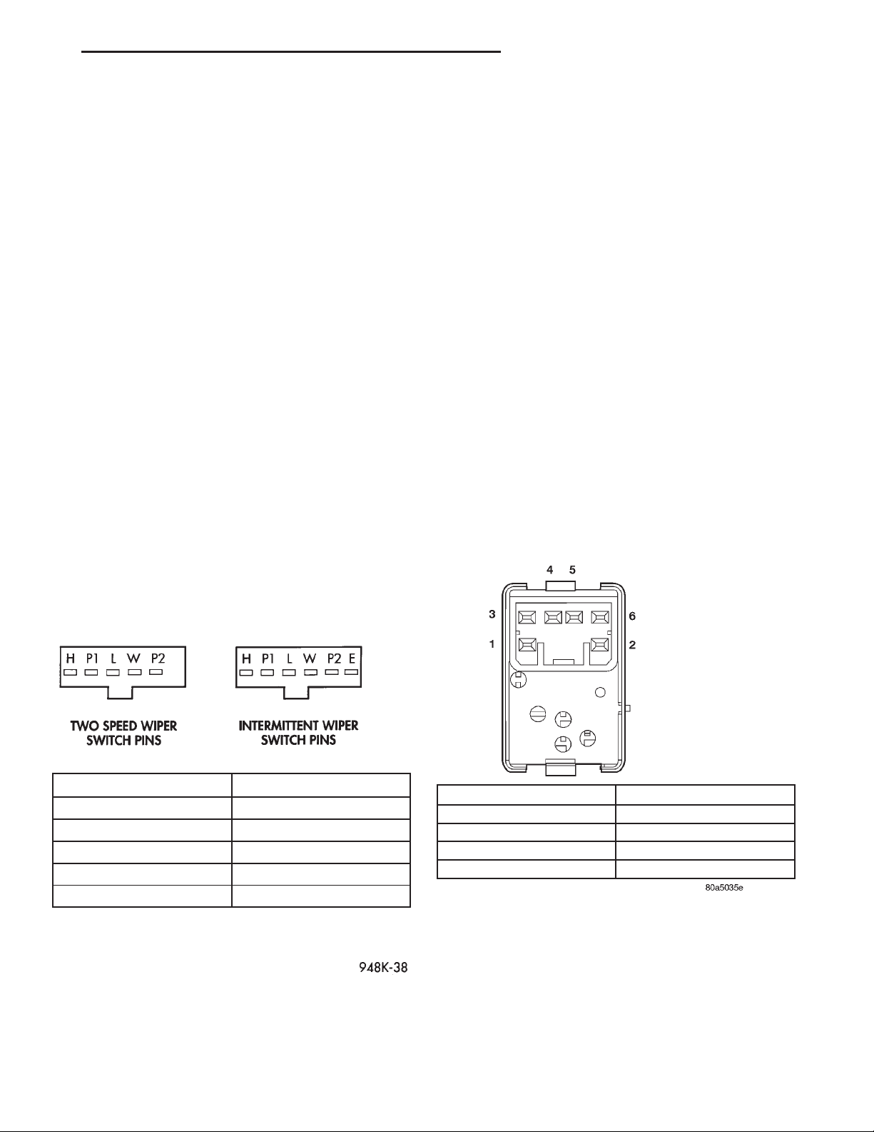
(3) Using an ohmmeter, perform the switch continuity checks at the switch terminals as shown in the
Windshield Wiper Switch and Washer Switch Continuity chart (Fig. 2).
the wiper system and/or washer system wire harness
circuits as required.
REAR
Perform the diagnosis for the rear wiper system
and/or washer system as described in this group
before testing the rear wiper and washer switch. For
circuit descriptions and diagrams, see 8W-53 - Wipers in Group 8W - Wiring Diagrams.
WARNING: ON VEHICLES EQUIPPED WITH AIRBAGS, REFER TO GROUP 8M - PASSIVE
RESTRAINT SYSTEMS BEFORE ATTEMPTING ANY
STEERING WHEEL, STEERING COLUMN, OR
INSTRUMENT PANEL COMPONENT DIAGNOSIS OR
SERVICE. FAILURE TO TAKE THE PROPER PRECAUTIONS COULD RESULT IN ACCIDENTAL AIRBAG DEPLOYMENT AND POSSIBLE PERSONAL
INJURY.
(1) Remove the accessory switch bezel from the
instrument panel and unplug the rear wiper and
washer switch wire harness connector.
(2) Using an ohmmeter, check the rear wiper and
washer switch continuity at the switch terminals as
shown in the Rear Wiper Switch and Washer Switch
Continuity chart (Fig. 3).
SWITCH POSITION CONTINUITY BETWEEN
OFF PIN P2 AND PIN L
LOW PIN P1 AND PIN L
HIGH PIN P1 AND PIN H
WASH PIN P1 AND PIN W
INTERMITTENT CANNOT BE CHECKED
Fig. 2 Windshield Wiper Switch and Washer Switch
Continuity
(4) If the switch fails any of the continuity checks,
replace the faulty switch. If the switch is OK, repair
SWITCH POSITION CONTINUITY BETWEEN
OFF 1 AND 4
WIPE 4 AND 5
WASH 2 AND 5, 4 AND 5
ILLUMINATION LAMP 1 AND 3
Fig. 3 Rear Wiper Switch and Washer Switch
Continuity
(3) If the switch fails any of the continuity checks,
replace the faulty switch. If the switch is OK, repair
the rear wiper system and/or washer system wire
harness circuits as required.
Page 8
8K - 8 WIPER AND WASHER SYSTEMS XJ
REMOVAL AND INSTALLATION
WIPER BLADE
FRONT
NOTE: The notched retainer end of the wiper element should always be oriented towards the end of
the wiper blade that is nearest to the wiper pivot.
(1) Lift the wiper arm to raise the wiper blade and
element off of the windshield glass.
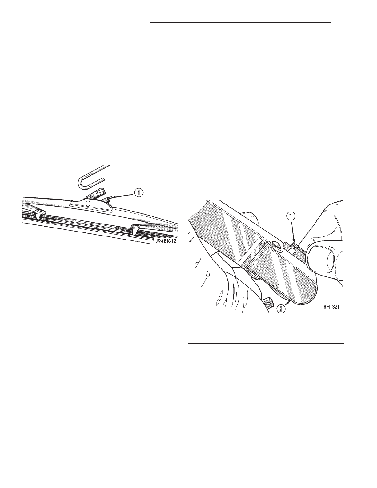
(2) To remove the wiper blade from the wiper arm,
push the release tab under the arm tip and slide the
blade away from the tip towards the pivot end of the
arm (Fig. 4).
(3) To install the wiper blade on the wiper arm,
slide the blade retainer into the U-shaped formation
on the tip of the wiper arm until the release tab
snaps into its locked position. Be certain that the
notched retainer for the wiper element is oriented
towards the end of the wiper blade that is nearest to
the rear wiper motor output shaft.
WIPER ARM
CAUTION: The use of a screwdriver or other prying
tool to remove a wiper arm may distort it. This distortion could allow the arm to come off of the pivot
shaft, regardless of how carefully it is installed.
FRONT
(1) Lift the wiper arm to permit the latch to be
pulled out to its holding position, then release the
arm (Fig. 5). The arm will remain off the windshield
with the latch in this position.
Fig. 4 Wiper Blade Remove/Install - Typical
1 – RELEASE TAB
(3) To install the wiper blade on the wiper arm,
slide the blade retainer into the U-shaped formation
on the tip of the wiper arm until the release tab
snaps into its locked position. Be certain that the
notched retainer for the wiper element is oriented
towards the end of the wiper blade that is nearest to
the wiper pivot.
REAR
NOTE: The notched retainer end of the wiper element should always be oriented towards the end of
the wiper blade that is nearest to the wiper pivot.
(1) Lift the rear wiper arm to raise the wiper blade
and element off of the rear liftglass.
(2) To remove the wiper blade from the wiper arm,
push the release tab under the arm tip and slide the
blade away from the tip towards the rear wiper
motor output shaft end of the arm (Fig. 4).
Fig. 5 Wiper Arm Remove/Install
1 – LOCKING LATCH
2 – ARM
(2) Remove the arm from the pivot using a rocking
motion.
(3) Install the arm and blade with the wiper motor
in the Park position. See the Front Wiper Arm
Installation illustration (Fig. 6).
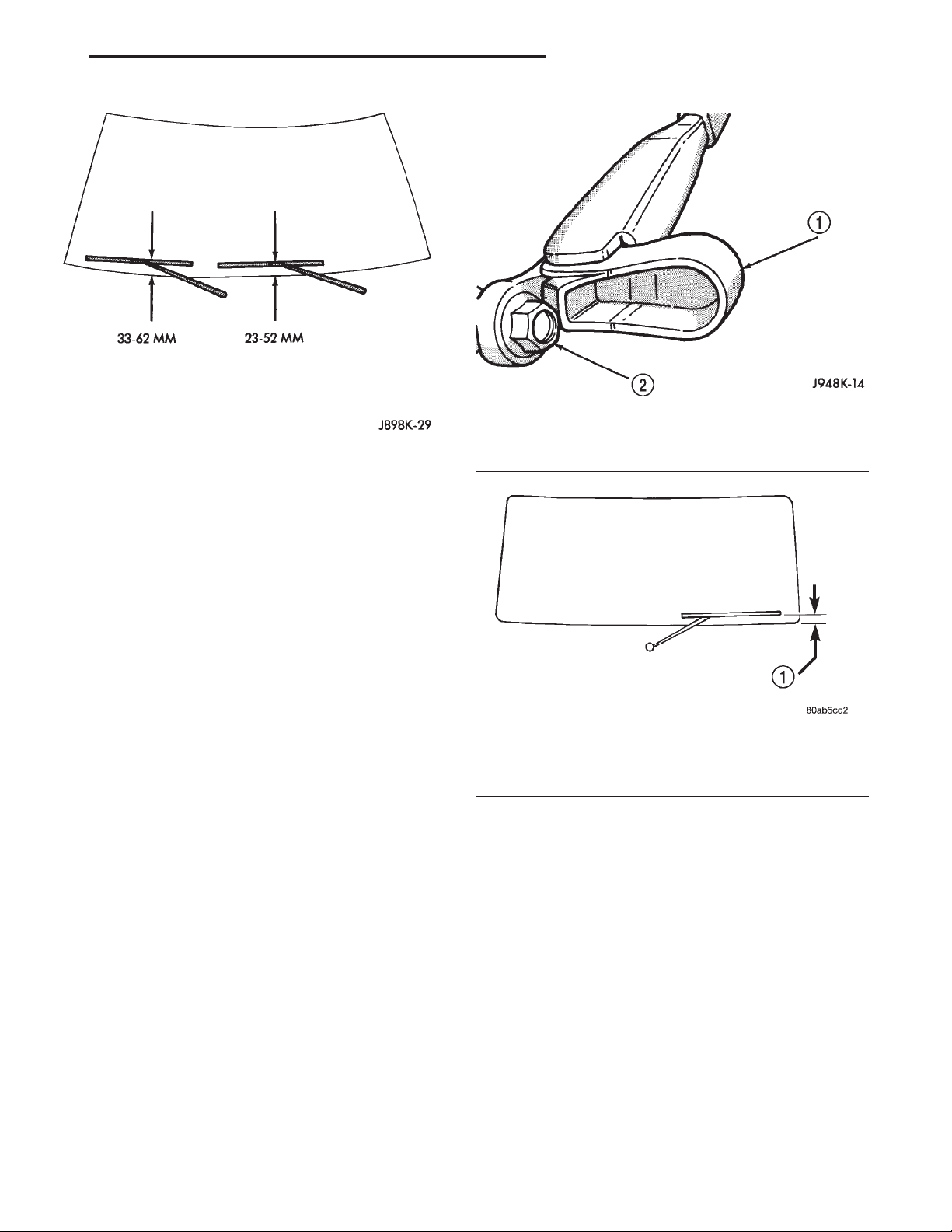
(4) Mount the arms on the pivot shafts so that the
distance from the lower edge of the wiper arm tip to
the upper edge of the lower windshield moulding is:
• 23 to 52 mm (0.90 to 2.04 inch) on the driver
side
Page 9
XJ WIPER AND WASHER SYSTEMS 8K - 9
REMOVAL AND INSTALLATION (Continued)
Fig. 7 Rear Wiper Arm Remove/Install
Fig. 6 Front Wiper Arm Installation
• 33 to 62 mm (1.29 to 2.44 inch) on the passenger
side.
(5) Lift the wiper arm away from the windshield
slightly to relieve the spring tension on the latch.
Push the latch into the locked position and slowly
release the arm until the wiper blade rests on the
windshield.
(6) Operate the wipers with the windshield glass
wet, then turn the wiper switch to the Off position.
Check for the correct wiper arm positioning and
readjust if required.
1 – PIVOT COVER
2 – WIPER ARM RETAINING NUT
REAR
(1) Disconnect the washer nozzle hose and clip
from the external nipple of the rear wiper motor output shaft bezel.
(2) Lift the wiper arm pivot cover and remove the
retaining nut (Fig. 7).
(3) Remove the wiper arm from the motor output
shaft using a rocking motion.
(4) Install the rear wiper arm with the wiper
motor in the Park position. Place the rear wiper
blade on the glass so that it is parallel to the liftgate
glass opening, and install the wiper arm retaining
nut.
(5) Operate the rear wiper with the liftgate glass
wet, then turn the rear wiper switch to the Off position so that the blade moves to the Park position.
(6) The measurement from the tip of the blade
should now be from 27 to 35 mm (1.06 to 1.38 inch)
above the upper edge of the lower liftgate glass seal
(Fig. 8). Check for the correct wiper arm positioning
and readjust if required.
Fig. 8 Rear Wiper Arm Installation
1 – IN PARKED POSITION —27 TO 35 mm (1.06 TO 1.38 INCH)
ABOVE UPPER EDGE OF LOWER GLASS SEALAT TIP OF
WIPER BLADE
(7) Tighten the wiper arm retaining nut to 18 N·m
(160 in. lbs.) and close the pivot cover.
WIPER LINKAGE AND PIVOT
The wiper linkage and pivots can only be removed
from or installed in the vehicle as a unit with the
wiper motor. See Wiper Motor in this group for the
service procedures.
WIPER MOTOR
FRONT
(1) Disconnect and isolate the battery negative
cable.
Page 10
8K - 10 WIPER AND WASHER SYSTEMS XJ
REMOVAL AND INSTALLATION (Continued)
(2) Remove the wiper arms from the wiper pivots.
See Wiper Arm in this group for the procedures.
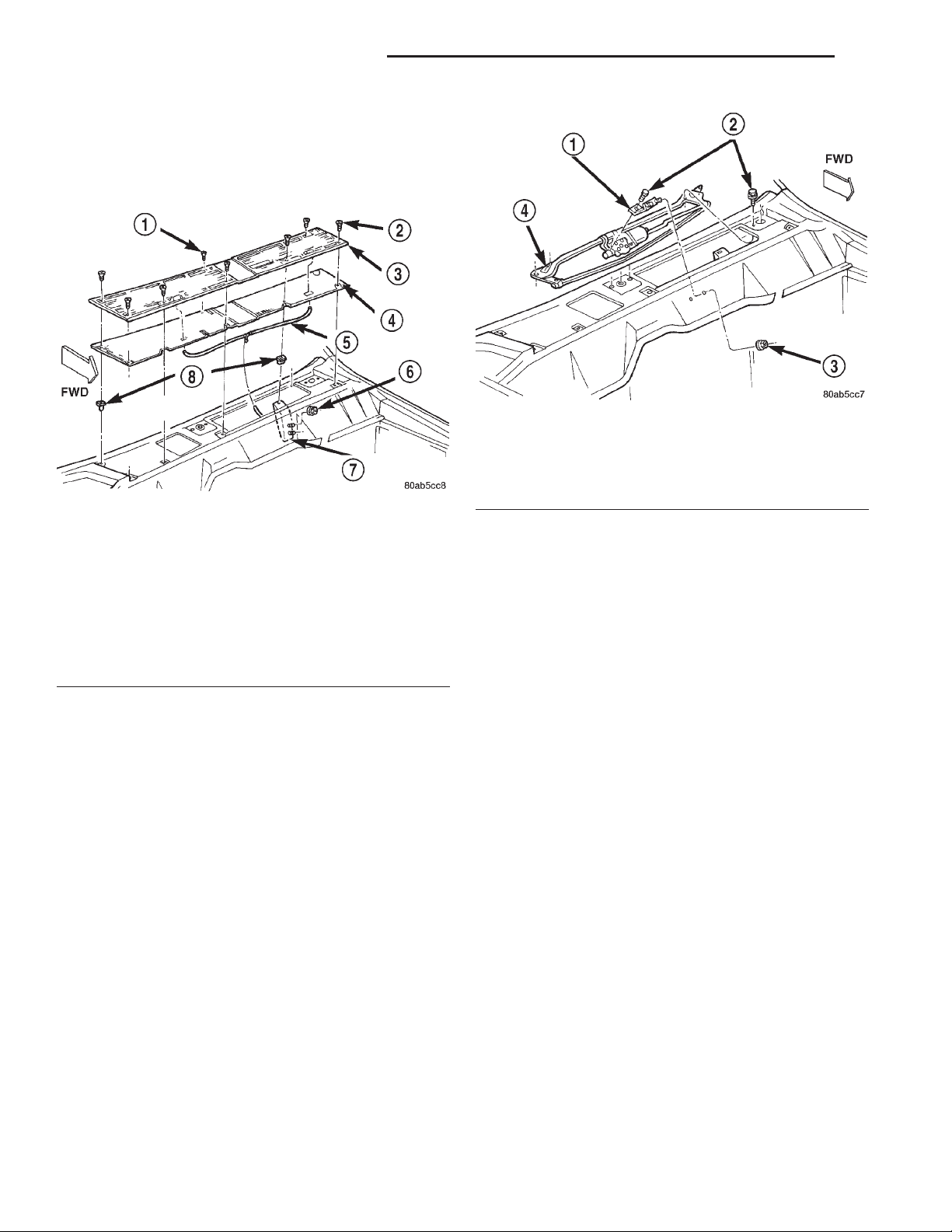
(3) Remove the eight screws that secure the cowl
plenum cover/grille panel and screen to the cowl top
panel (Fig. 9).
Fig. 10 Wiper Linkage Module Remove/Install
1 – BRACKETAND GROMMET
2 – SCREW
3 – NUT
4 – LINKAGE AND PIVOT MODULE
Fig. 9 Cowl Plenum Cover/Grille Panel Remove/
Install
1 – SCREW
2 – SCREW
3 – GRILLE PANEL
4 – SCREEN
5 – WASHER HOSE
6 – NUT
7 – BRACKET
8 – NUT
(4) Carefully lift the cowl plenum cover/grille panel
and screen from the vehicle far enough to access the
windshield washer plumbing. Use care so as not to
damage the paint around the pivot openings of the
panel.
(5) Disconnect the windshield washer supply hose
and the passenger side washer nozzle hose from the
washer nozzle supply hose tee fitting.
(6) Remove the cowl plenum cover/grille panel and
screen from the vehicle.
(7) Reach into the cowl plenum and unplug the
wiper motor wire harness connector.
(8) Open and support the hood
(9) Remove the two nuts that secure the studs of
the wiper module mounting bracket and reinforcement to the dash panel (Fig. 10).
(10) Remove the four screws near the wiper pivots
that secure the wiper module to the cowl plenum
panel.
(11) Remove the wiper module from the cowl plenum as a unit.
(12) Reverse the removal procedures to install.
Tighten the mounting hardware as follows:
• Wiper module mounting screws - 6 N·m (50 in.
lbs.)
• Wiper module mounting bracket and reinforce-
ment nuts - 6 N·m (50 in. lbs.).
REAR
(1) Disconnect and isolate the battery negative
cable.
(2) From the outside of the liftgate glass, remove
the rear wiper arm from the rear wiper motor output
shaft. See Wiper Arm in this group for the procedures.
(3) From the outside of the liftgate, remove the
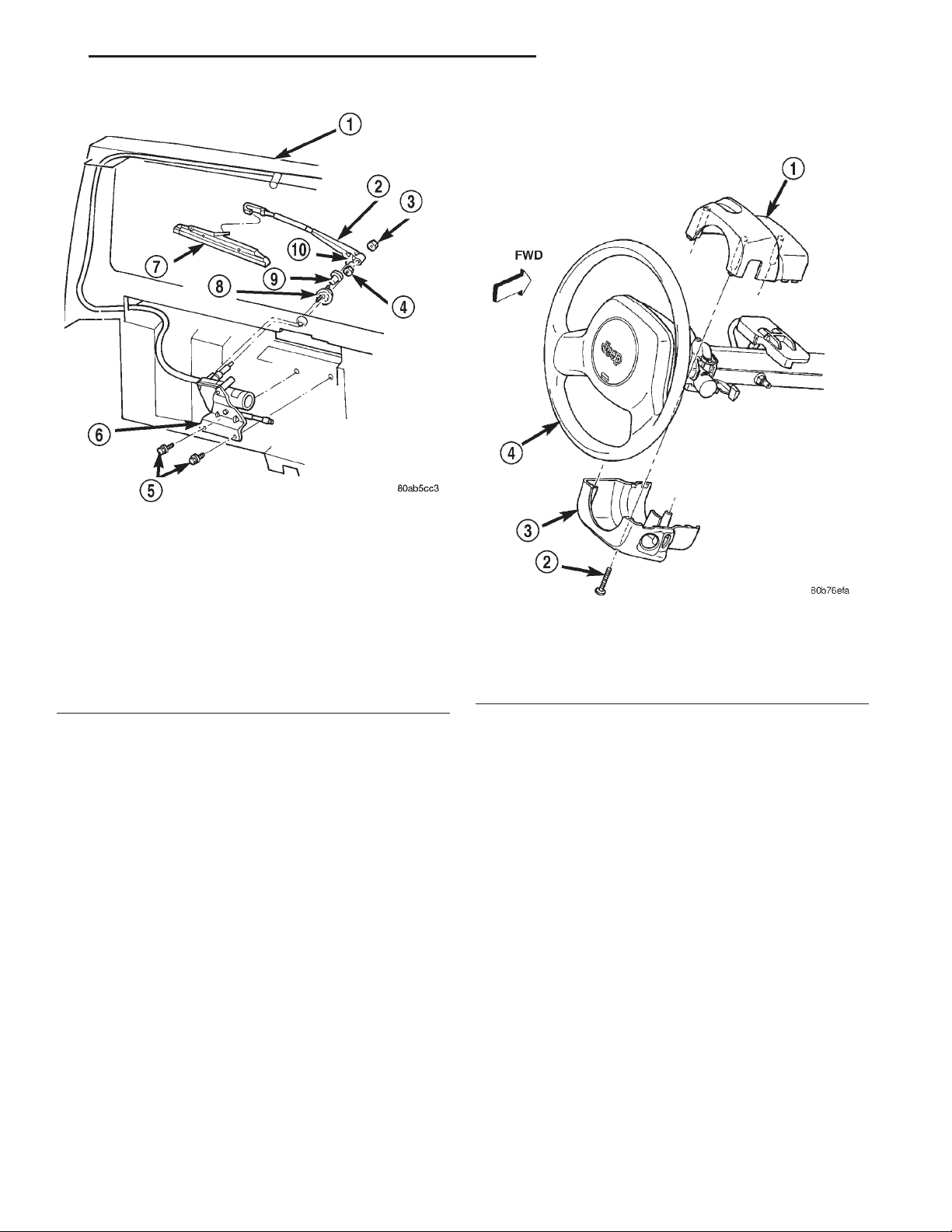
rear wiper motor output shaft nut (Fig. 11).
(4) Pull the rear wiper motor output shaft bezel
and rubber gasket away from the liftgate far enough
to access the washer supply hose.
(5) Disconnect the washer supply hose from the
internal nipple on the bezel.
(6) Remove the bezel and rubber gasket from the
motor output shaft.
(7) Remove the liftgate trim panel from the liftgate. Refer to Group 23 - Body for the procedures.
(8) Unplug the rear wiper motor wire harness connector.
(9) Remove the two screws that secure the rear
wiper motor mounting bracket to the liftgate inner
panel.
(10) Remove the rear wiper motor and mounting
bracket from the liftgate as a unit.
(11) Reverse the removal procedures to install.
Tighten the mounting hardware as follows:
• Rear wiper motor mounting bracket screws - 5
N·m (45 in. lbs.)
Page 11
XJ WIPER AND WASHER SYSTEMS 8K - 11
REMOVAL AND INSTALLATION (Continued)
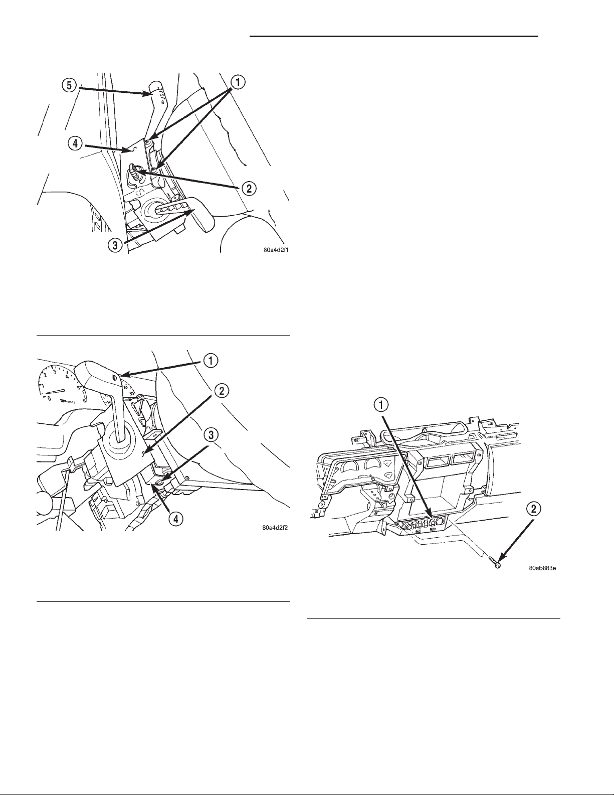
(3) Remove the three screws that secure the lower
steering column shroud to the upper shroud (Fig. 12).
Fig. 11 Rear Wiper Motor Remove/Install
1 – LIFTGATE
2 – ARM
3 – NUT
4 – NUT
5 – SCREW
6 – MOTORAND BRACKET
7 – BLADE
8 – BEZEL
9 – CLIP
10 – HOSE
• Rear wiper motor output shaft retaining nut - 3
N·m (27 in. lbs.).
WIPER SWITCH AND WASHER SWITCH
FRONT
WARNING: ON VEHICLES EQUIPPED WITH AIRBAGS, REFER TO GROUP 8M - PASSIVE
RESTRAINT SYSTEMS BEFORE ATTEMPTING ANY
STEERING WHEEL, STEERING COLUMN, OR
INSTRUMENT PANEL COMPONENT DIAGNOSIS OR
SERVICE. FAILURE TO TAKE THE PROPER PRECAUTIONS COULD RESULT IN ACCIDENTAL AIRBAG DEPLOYMENT AND POSSIBLE PERSONAL
INJURY.
(1) Disconnect and isolate the battery negative
cable.
(2) Remove the knee blocker from the instrument
panel. See Knee Blocker in Group 8E - Instrument
Panel Systems for the procedures.
Fig. 12 Steering Column Shrouds Remove/Install
1 – UPPER SHROUD
2 – SCREW (3)
3 – LOWER SHROUD
4 – STEERING WHEEL
(4) If the vehicle is equipped with a standard nontilt steering column, loosen the two upper steering
column mounting nuts. If the vehicle is equipped
with the optional tilt steering column, move the tilt
steering column to the fully lowered position.
(5) Remove both the upper and lower shrouds from
the steering column.
(6) Remove the two screws that secure the switch
water shield and bracket to the top of the steering
column (Fig. 13).
(7) Remove the one screw located below the multifunction switch lever that secures the switch water
shield and bracket to the steering column (Fig. 14).
(8) Gently pull the lower mounting tab of the
switch water shield bracket away from the steering
column far enough to clear the screw boss below the
multi-function switch lever.
(9) Lift the water shield and bracket with the
multi-function switch off of the left side of the steering column as a unit and move it out of the way. If
the vehicle is equipped with the optional tilt steering
column, lifting gently upward on the tilt release lever
Page 12
8K - 12 WIPER AND WASHER SYSTEMS XJ
REMOVAL AND INSTALLATION (Continued)
(13) Reverse the removal procedures to install.
Tighten the upper switch mounting screws to 2.2
N·m (20 in. lbs.). Tighten the lower switch water
shield and bracket screw to 1.1 N·m (10 in. lbs.).
Tighten the non-tilt steering column mounting nuts
to 22 N·m (200 in. lbs.) and the steering column
shroud mounting screws to 2 N·m (18 in. lbs.).
REAR
WARNING: ON VEHICLES EQUIPPED WITH AIRBAGS, REFER TO GROUP 8M - PASSIVE
RESTRAINT SYSTEMS BEFORE ATTEMPTING ANY
STEERING WHEEL, STEERING COLUMN, OR
INSTRUMENT PANEL COMPONENT DIAGNOSIS OR
SERVICE. FAILURE TO TAKE THE PROPER PRE-
Fig. 13 Water Shield Upper Screws Remove/Install
1 – MOUNTING SCREWS
2 – HAZARD WARNING SWITCH KNOB
3 – MULTI-FUNCTION SWITCH LEVER
4 – WATER SHIELD AND BRACKET
5 – WIPER SWITCH LEVER
CAUTIONS COULD RESULT IN ACCIDENTAL AIRBAG DEPLOYMENT AND POSSIBLE PERSONAL
INJURY.
(1) Disconnect and isolate the battery negative
cable.
(2) Remove the center bezel from the instrument
panel. See Instrument Panel Center Bezel in Group
8E - Instrument Panel Systems for the procedures.
(3) Remove the three screws that secure the accessory switch bezel to the instrument panel (Fig. 15).
Fig. 14 Water Shield Lower Screw Remove/Install
1 – MULTI-FUNCTION SWITCH LEVER
2 – WATER SHIELD AND BRACKET
3 – LOWER MOUNTING SCREW
4 – LOWER MOUNTING TAB
will provide additional clearance to ease multi-function switch removal.
(10) Gently pull the windshield wiper and washer
switch up and away from the right side of the steering column far enough to access the wire harness
connector.
(11) Unplug the wire harness connector from the
windshield wiper and washer switch.
(12) Remove the windshield wiper and washer
switch from the steering column.
Fig. 15 Accessory Switch Bezel Remove/Install
1 – ACCESSORY SWITCH BEZEL
2 – SCREW
(4) Pull the accessory switch bezel out from the
instrument panel far enough to access the wire harness connectors.
(5) Unplug the wire harness connectors from the
rear of the accessory switches, the cigar lighter and
the power outlet.
(6) Remove the accessory switch bezel from the
instrument panel.
(7) With a small thin-bladed screwdriver, gently
pry the snap clips at the top and bottom of the rear
Page 13
XJ WIPER AND WASHER SYSTEMS 8K - 13
REMOVAL AND INSTALLATION (Continued)
wiper and washer switch receptacle on the back of
the accessory switch bezel and pull the switch out of
the bezel.
(8) Reverse the removal procedures to install. Be
certain that both of the switch snap clip retainers in
the receptacle on the back of the accessory switch
bezel are fully engaged. Tighten the mounting screws
to 2.2 N·m (20 in. lbs.).
WASHER SYSTEM
WASHER RESERVOIR
(1) Disconnect and isolate the battery negative
cable.
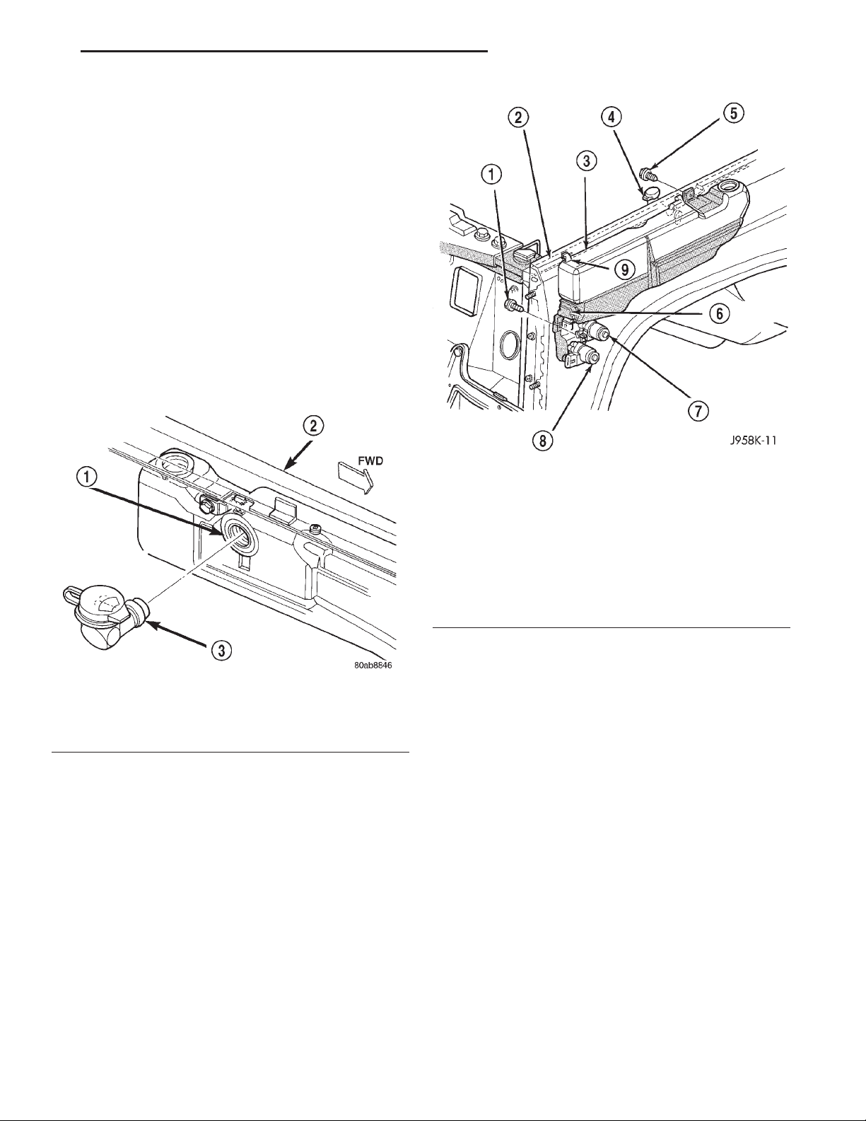
(2) The washer reservoir filler neck is held in the
reservoir by an interference fit. Remove the filler
neck from the reservoir using a combination of pulling, rocking and twisting actions (Fig. 16).
Fig. 16 Washer Reservoir Filler Neck Remove/Install
1 – RESERVOIR
2 – LEFT FENDER
3 – FILLER NECK AND CAP
(3) Remove the engine air filter housing. Refer to
Group 14 - Fuel System for the procedures.
(4) Remove the two screws that secure the washer
reservoir to the inner fender shield (Fig. 17).
(5) Raise and support the vehicle.
(6) Remove the left front inner wheelhouse splash
shield. Refer to Group 23 - Body for the procedures.
(7) Remove the washer supply hose(s) from the
washer pump(s) and drain the washer fluid from the
reservoir into a clean container for reuse.
(8) Unplug the wire harness connectors from the
washer pump(s) and the washer fluid level sensor.
(9) Slide the reservoir slightly towards the rear of
the vehicle to release the two hooks from the inner
fender ledge slots.
(10) Lower the front of the washer reservoir and
slide the unit forward to remove it from the vehicle.
Fig. 17 Washer Reservoir Remove/Install
1 – SCREW
2 – FENDER
3 – WASHER RESERVOIR
4 – FILLER NECK
5 – SCREW
6 – FLUID LEVEL SENSOR
7 – REAR WASHER PUMP
8 – FRONT WASHER PUMP
9 – HOOK
(11) Reverse the removal procedures to install.
Tighten the reservoir mounting screws to 3 N·m (26
in. lbs.).
WASHER PUMP
(1) Disconnect and isolate the battery negative
cable.
(2) Raise and support the vehicle.
(3) Remove the left front inner wheelhouse splash
shield. Refer to Group 23 - Body for the procedures.
(4) Remove the washer supply hose(s) from the
barbed outlet nipple of the washer pump(s) and drain
the washer fluid from the reservoir into a clean container for reuse.
(5) Unplug the wire harness connectors from the
washer pump(s).
(6) Using a trim stick or another suitable wide
flat-bladed tool, gently pry the barbed inlet nipple of
the washer pump out of the rubber grommet seal in
the reservoir. Care must be taken not to damage the
reservoir.
(7) Remove the rubber grommet seal from the reservoir and discard.
Page 14
8K - 14 WIPER AND WASHER SYSTEMS XJ
REMOVAL AND INSTALLATION (Continued)
(8) Reverse the removal procedures to install.
Always use a new rubber grommet seal on the reservoir.
WASHER FLUID LEVEL SENSOR
(1) Remove the washer reservoir from the vehicle.
See Washer Reservoir in this group for the procedures.
NOTE: The pivoting float of the washer fluid sensor
must be in a horizontal position within the reservoir
in order to be removed. With the reservoir empty
and in an upright position, the pivoting float will orient itself to the horizontal position when the sensor
connector is pointed straight downwards.
(2) Using a trim stick or another suitable wide
flat-bladed tool, gently pry the washer fluid level sensor out of the rubber grommet seal. Care must be
taken not to damage the reservoir.
(3) Remove the rubber grommet seal from the reservoir and discard.
(4) Reverse the removal procedures to install.
Always use a new rubber grommet seal on the reservoir.
(3) Carefully lift the cowl plenum cover/grille panel
and screen from the vehicle far enough to access the
windshield washer plumbing. Use care so as not to
damage the paint around the pivot openings of the
panel.
(4) Disconnect the windshield washer supply hose
and the passenger side washer nozzle hose from the
washer nozzle supply hose tee fitting.
(5) Remove the cowl plenum cover/grille panel and
screen from the vehicle.
(6) From the underside of the cowl plenum cover/
grille panel, disconnect the washer hose from the
nozzle fitting.
(7) From the underside of the cowl plenum cover/
grille panel, remove the rivet that secures the nozzle
to the opening in the cowl plenum cover/grille panel.
(8) Remove the washer nozzle from the cowl plenum cover/grille panel.
(9) Reverse the removal procedures to install.
REAR
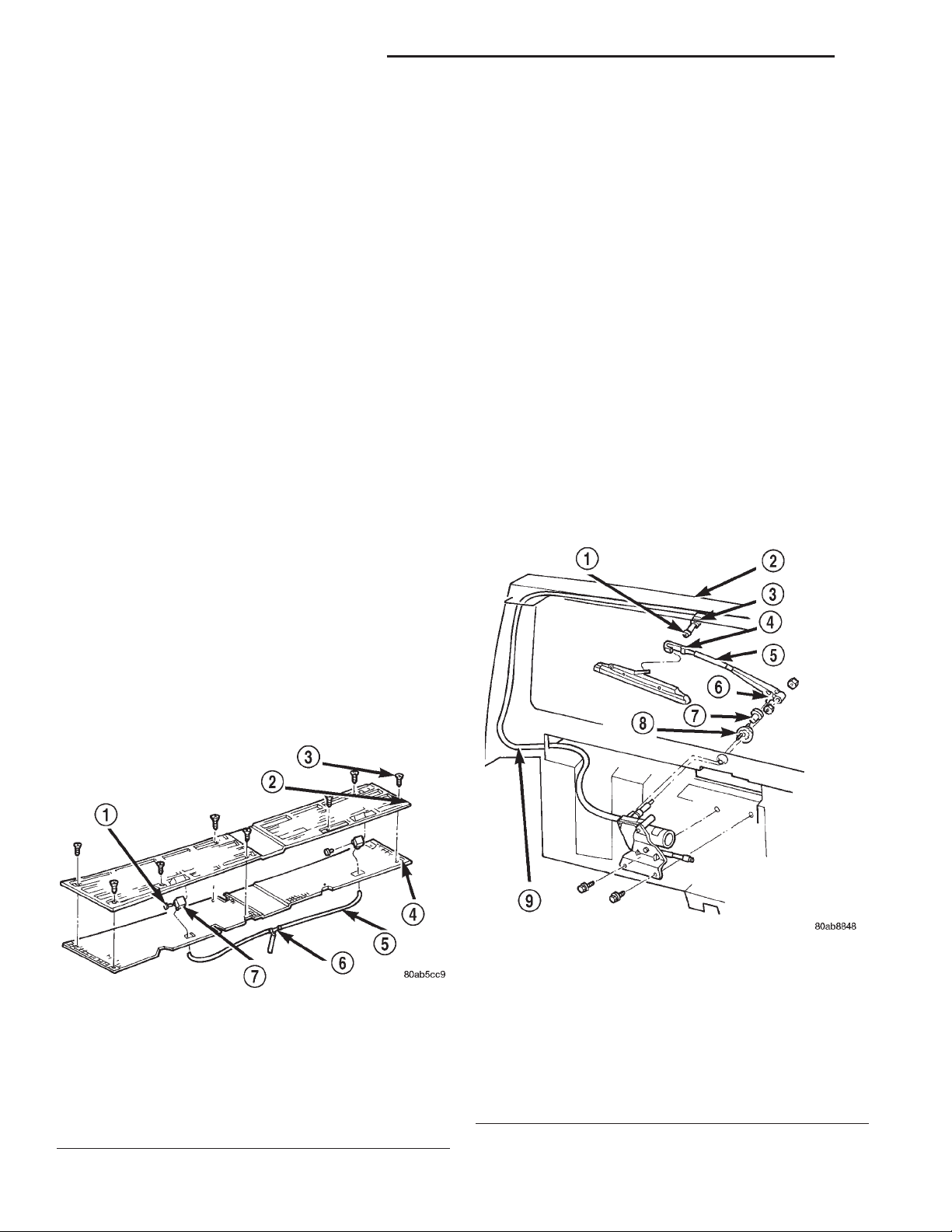
(1) Unsnap the rear washer nozzle from the rear
wiper arm (Fig. 19).
WASHER NOZZLE
FRONT
(1) Remove the wiper arms from the wiper pivots.
See Wiper Arm in this group for the procedures.
(2) Remove the eight screws that secure the cowl
plenum cover/grille panel and screen to the cowl top
panel (Fig. 18).
Fig. 18 Front Washer Nozzles Remove/Install
1 – RIVET
2 – GRILLE PANEL
3 – SCREW
4 – SCREEN
5 – WASHER HOSE
6 – TEE
7 – NOZZLE
Fig. 19 Rear Washer Nozzle Remove/Install
1 – TO CHECK VALVE AND BODY SUPPLY HOSE
2 – LIFTGATE
3 – GROMMET
4 – NOZZLE
5 – GUARD
6 – HOSE
7 – CLIP
8 – BEZEL
9 – LIFTGATE SUPPLY HOSE
Page 15
XJ WIPER AND WASHER SYSTEMS 8K - 15
REMOVAL AND INSTALLATION (Continued)
(2) Disconnect the washer supply hose from the
barbed rear washer nozzle nipple.
(3) Reverse the removal procedures to install.
CHECK VALVE
(1) Remove the four screws that secure the liftgate
opening upper garnish moulding to the upper liftgate
opening reinforcement.
(2) Using a trim stick or another suitable widebladed flat tool, gently pry the liftgate opening upper
garnish moulding away from the upper liftgate opening reinforcement to release the snap clip retainers.
(3) Remove the garnish moulding from the upper
liftgate opening.
(4) Disconnect the liftgate half of the washer supply hose from the barbed nipple of the rear washer
system check valve.
(5) Disconnect the body half of the washer supply
hose from the other barbed nipple of the rear washer
system check valve.
(6) Remove the check valve from the vehicle.
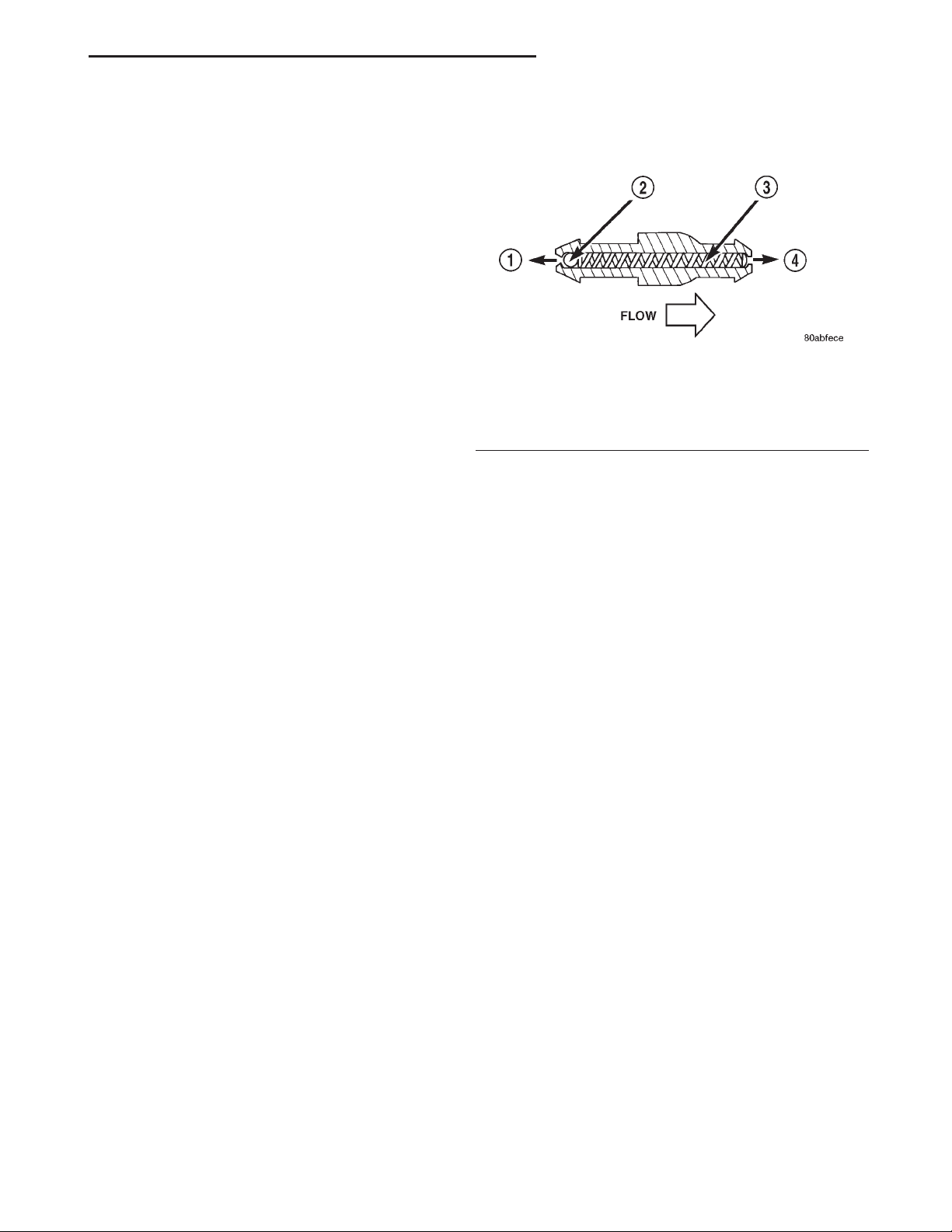
(7) When reinstalling the check valve, be certain
the valve is properly oriented within the system flow
(Fig. 20).
Fig. 20 Rear Washer System Check Valve
1 – TO RESERVOIR
2 – CHECKBALL
3 – SPRING
4 – TO NOZZLE
(8) Reverse the remaining removal procedures to
complete the installation.
Page 16

 Loading...