

Page 1

XJ TURN SIGNAL AND HAZARD WARNING SYSTEMS 8J - 1
TURN SIGNAL AND HAZARD WARNING SYSTEMS
TABLE OF CONTENTS
page page
DESCRIPTION AND OPERATION
TURN SIGNAL SYSTEM....................1
HAZARD WARNING SYSTEM................1
TURN SIGNAL SWITCH AND HAZARD
WARNING SWITCH ......................2
TURN SIGNAL CANCELLING CAM............3
COMBINATION FLASHER ...................3
DIAGNOSIS AND TESTING
TURN SIGNAL AND HAZARD WARNING
SYSTEMS .............................4
DESCRIPTION AND OPERATION
TURN SIGNAL SYSTEM
DESCRIPTION
A turn signal system is standard factory-installed
safety equipment on this model. The turn signal system uses ignition switched battery current, and will
operate only when the ignition switch is in the On or
Accessory positions. The turn signal system includes
the following components:
• Combination flasher
• Front side marker lamps
• Turn signal cancelling cam
• Turn signal indicator lamps
• Turn signal lamps
• Turn signal switch.
Refer to Lamp in the proper section of Group 8L Lamps for more information on the exterior turn signal lamps. Refer to Instrument Cluster in the
proper section of Group 8E - Instrument Panel Systems for more information on the turn signal indicator lamps. Following are general descriptions of the
major components in the turn signal system. For
complete circuit diagrams, refer to Turn Signals in
the Contents of Group 8W - Wiring Diagrams.
OPERATION
With the ignition switch in the On or Accessory
position, and the turn signal (multi-function) switch
control stalk moved up (right turn) or down (left
turn), the turn signal system is activated. When the
turn signal system is activated, the circuitry of the
turn signal switch and the combination flasher will
cause the selected (right or left) turn signal indicator
lamp, front park/turn signal lamp, front side marker
TURN SIGNAL SWITCH AND HAZARD
WARNING SWITCH ......................5
REMOVAL AND INSTALLATION
COMBINATION FLASHER ...................5
TURN SIGNAL SWITCH AND HAZARD
WARNING SWITCH ......................6
lamp and rear tail/stop/turn signal lamp to flash on
and off. If the exterior lamps are turned off, the front
park/turn signal lamp and the front side marker
lamp will flash in unison. If the exterior lamps are
turned on, the front park/turn signal lamp and the
front side marker lamp will flash alternately.
See the owner’s manual in the vehicle glove box for
more information on the features, use and operation
of the turn signal system.
HAZARD WARNING SYSTEM
DESCRIPTION
A hazard warning system is standard factory-installed safety equipment on this model. Unlike the
turn signal system, the hazard warning system uses
a non-switched source of battery current so that the
system will operate regardless of the ignition switch
position. The hazard warning system includes the following components:
• Combination flasher
• Front side marker lamps
• Hazard warning switch
• Turn signal indicator lamps
• Turn signal lamps.
Refer to Lamp in the proper section of Group 8L Lamps for more information on the exterior turn signal lamps. Refer to Instrument Cluster in the
proper section of Group 8E - Instrument Panel Systems for more information on the turn signal indicator lamps. Following are general descriptions of the
major components in the hazard warning system. For
complete circuit diagrams, refer to Turn Signals in
the Contents of Group 8W - Wiring Diagrams.
Page 2
8J - 2 TURN SIGNAL AND HAZARD WARNING SYSTEMS XJ
DESCRIPTION AND OPERATION (Continued)
OPERATION
With the hazard warning switch in the On position, the hazard warning system is activated. When
the hazard warning system is activated, the circuitry
of the hazard warning switch and the combination
flasher will cause both the right side and the left side
turn signal indicator lamps, front park/turn signal
lamps, front side marker lamps and rear tail/stop/
turn signal lamps to flash on and off. If the exterior
lamps are turned off, the front park/turn signal
lamps and the front side marker lamps will flash in
unison. If the exterior lamps are turned on, the front
park/turn signal lamps and the front side marker
lamps will flash alternately.
See the owner’s manual in the vehicle glove box for
more information on the features, use and operation
of the hazard warning system.
TURN SIGNAL SWITCH AND HAZARD WARNING SWITCH
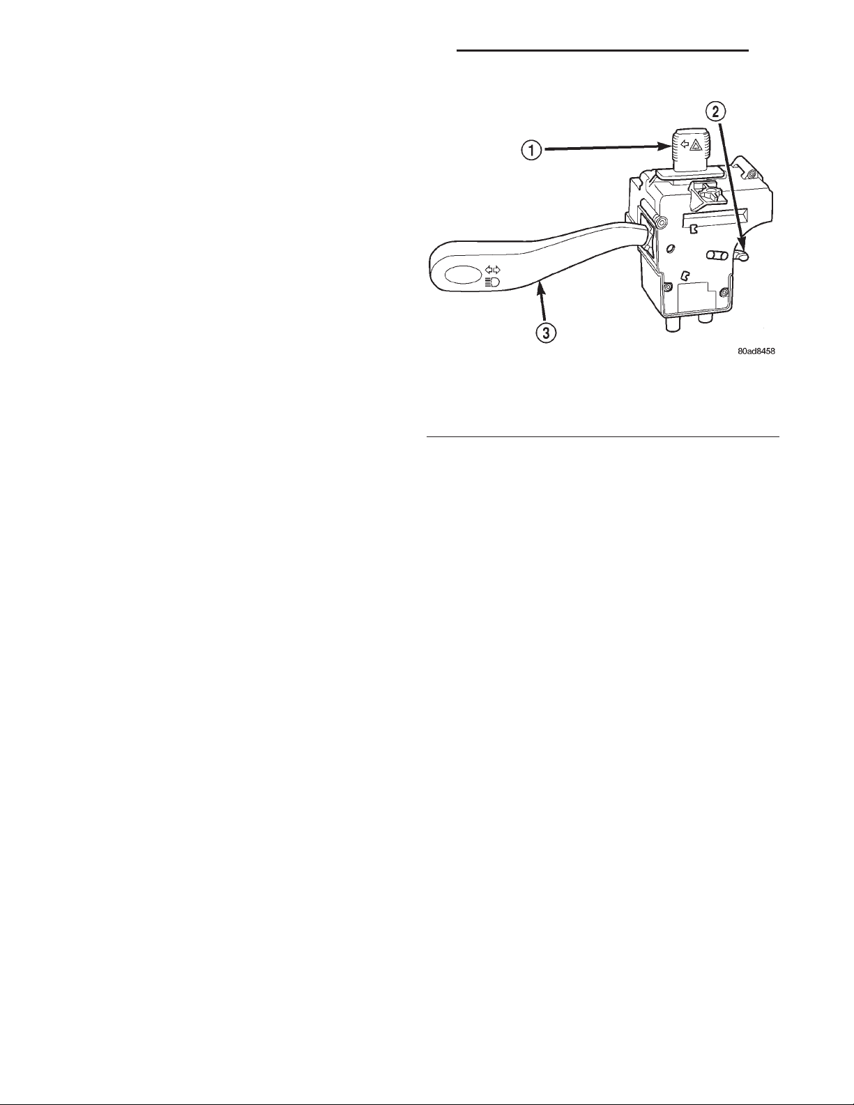
1 – HAZARD WARNING BUTTON
2 – CANCEL ACTUATOR
3 – CONTROL STALK
Fig. 1 Multi-Function Switch
DESCRIPTION
The turn signal and hazard warning switches are
integral to the multi-function switch unit, which is
secured to the left side of the steering column (Fig.
1). The only visible parts of the multi-function switch
are the control stalk that extends from the left side
of the steering column, and the hazard warning
switch button that protrudes from the top of the
steering column. The multi-function switch control
stalk has international control symbols on it, which
identify its functions. The hazard warning switch
button is identified with a double triangle, which is
the international control symbol for hazard warning.
The remainder of the multi-function switch is concealed beneath the steering column shrouds.
The multi-function switch also contains circuitry
for the following functions:
• Headlamp beam selection
• Headlamp optical horn
The information contained in this group addresses
only the multi-function switch turn signal and hazard warning functions. For information relative to
the other systems that are controlled by and circuits
that are integral to the multi-function switch, see the
group in this service manual that covers that system.
However, the turn signal and hazard warning
switches cannot be repaired. If these switches or any
other circuit or component of the multi-function
switch unit is faulty or damaged, the entire multifunction switch unit must be replaced.
OPERATION
TURN SIGNAL SWITCH
The multi-function switch control stalk that
extends from the left side of the steering column just
below the steering wheel is moved up or down to
activate the turn signal switch. When the control
stalk is moved in the upward direction, the right
turn signal switch circuitry is activated; and, when
the control stalk is moved in the downward direction,
the left turn signal switch circuitry is activated. The
turn signal switch has a detent position in each
direction that provides turn signals with automatic
cancellation, and an intermediate momentary position in each direction that provides turn signals only
until the multi-function switch control stalk is
released.
When the turn signal switch is in a detent position, it is turned off by one of two turn signal cancelling cam lobes that are integral to the rotor of the
clockspring mechanism. Turning the steering wheel
causes the turn signal cancelling cam lobes to contact
a cancel actuator in the multi-function switch, and
the turn signal switch automatically returns to the
off position.
HAZARD WARNING SWITCH
The hazard warning switch is controlled by the
hazard warning switch button. Slide the switch button to the left to turn the switch on and activate the
hazard warning system, and slide the button to the
right again to turn the switch and the hazard warning system off.
Page 3

XJ TURN SIGNAL AND HAZARD WARNING SYSTEMS 8J - 3
DESCRIPTION AND OPERATION (Continued)
TURN SIGNAL CANCELLING CAM
DESCRIPTION
The turn signal cancelling cam is concealed within
the steering column below the steering wheel. The
turn signal cancelling cam consists of two lobes that
are integral to the lower surface of the clockspring
rotor. The clockspring mechanism provides turn signal cancellation as well as a constant electrical connection between the horn switch, driver side airbag
module and speed control switches on the steering
wheel and the instrument panel wire harness on the
steering column. The housing of the clockspring is
secured to the steering column and remains stationary. The rotor of the clockspring, including the turn
signal cancelling cam lobes rotate with the steering
wheel.
The turn signal cancelling cam is integral to the
clockspring and cannot be repaired. If faulty or damaged, the entire clockspring assembly must be
replaced. Refer to Clockspring in the Removal and
Installation section of Group 8M - Passive Restraint
Systems for the clockspring service procedures.
OPERATION
The turn signal cancelling cam has two lobes
molded into the lower surface of the clockspring
rotor. When the turn signals are activated by moving
the multi-function switch control stalk to a detent
position, a turn signal cancel actuator is extended
from the inside surface of the multi-function switch
housing toward the clockspring rotor. When the
steering wheel is rotated during the turn, one of the
two turn signal cancelling cam lobes will contact the
turn signal cancel actuator, releasing the multi-function switch control stalk from its detent and cancelling the turn signal event.
COMBINATION FLASHER
DESCRIPTION
The combination flasher is a smart relay that functions as both the turn signal system and the hazard
warning system flasher. The combination flasher contains active electronic Integrated Circuitry (IC) elements. This flasher is designed to handle the current
flow requirements of the factory-installed lighting. If
supplemental lighting is added to the turn signal
lamp circuits, such as when towing a trailer with
lights, the combination flasher will automatically try
to compensate to keep the flash rate the same.
While the combination flasher has a International
Standards Organization (ISO)-type relay terminal
configuration or footprint, the internal circuitry is
much different. The combination flasher does not use
standard ISO-relay inputs or provide ISO-relay type
outputs or functions. The combination flasher should
never be substituted for an ISO-relay or replaced
with an ISO-relay, or else component and vehicle
damage may occur.
Because of the active electronic elements within
the combination flasher, it cannot be tested with conventional automotive electrical test equipment. If the
combination flasher is believed to be faulty, test the
turn signal system and hazard warning system circuits as described in this group. Then replace the
combination flasher with a known good unit to confirm system operation.
The combination flasher has five blade-type terminals intended for the following inputs and outputs:
fused B(+), fused ignition switch output, ground, turn
signal circuit, and hazard warning circuit. Constant
battery voltage and ground are supplied to the
flasher so that it can perform the hazard warning
function, and ignition switched battery voltage is
supplied for the turn signal function. Refer to Turn
Signals in the Contents of Group 8W - Wiring Diagrams for complete circuit diagrams.
The combination flasher is located in a wire harness connector which is secured to the diagnostics
splice block bracket outboard of the steering column
opening underneath the instrument panel. The combination flasher cannot be repaired or adjusted and,
if faulty or damaged, it must be replaced.
OPERATION
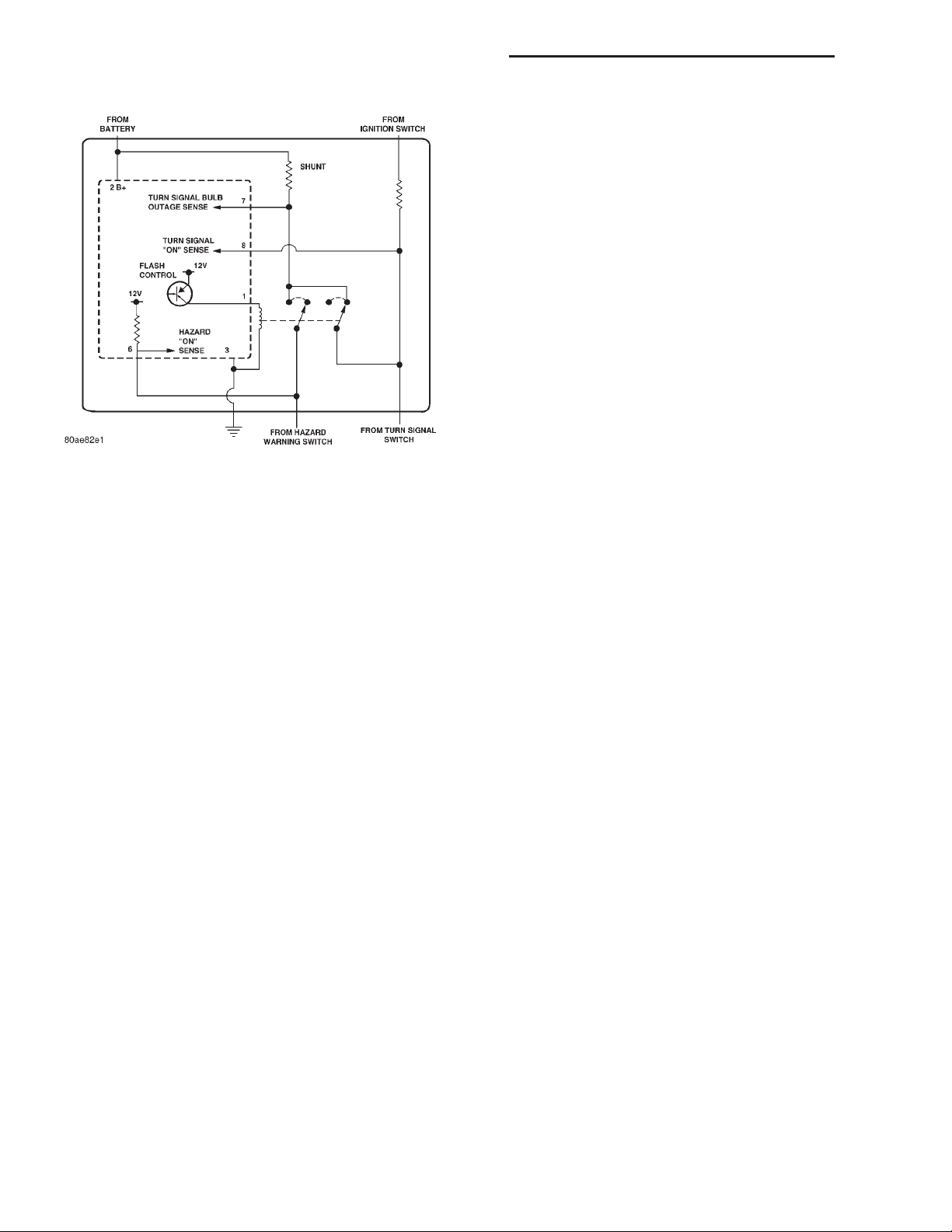
The IC within the combination flasher (Fig. 2) contains the logic that controls the flasher operation and
the flash rate. Pin 6 of the IC receives a sense voltage from the hazard warning circuit of the multifunction switch. When the hazard warning switch is
turned on, the 9hazard on sense” voltage will become
low due to the circuit being grounded through the
turn signal bulbs. This low voltage sense signals the
IC to energize the flash control Positive-NegativePositive (PNP) transistor at a pre-calibrated flash
rate or frequency. Each time the PNP transistor energizes the hazard warning circuit, the pin 6 “hazard
on sense” voltage will become high and the IC signals
the PNP transistor to de-energize the circuit. This
cycling will continue until the hazard warning switch
is turned off.
Likewise, pin 8 of the IC receives a sense voltage
from the turn signal circuits of the multi-function
switch. When the left or right turn signal switch is
turned on, the “turn signal on sense” voltage will
become low due to the circuit being grounded
through the turn signal bulbs. This low voltage sense
signals the IC to energize the flash control PNP transistor at a pre-calibrated flash rate or frequency.
Each time the PNP transistor energizes the turn signal circuit, the pin 8 “turn signal on sense” voltage
Page 4
8J - 4 TURN SIGNAL AND HAZARD WARNING SYSTEMS XJ
DESCRIPTION AND OPERATION (Continued)
If the problem being diagnosed is related to a failure of the turn signals to automatically cancel following completion of a turn, inspect the multi-function
switch for a faulty or damaged cancel actuator and
inspect the turn signal cancelling cam lobes on the
clockspring mechanism for damage or improper
installation. For complete circuit diagrams, refer to
Turn Signals in the Contents of Group 8W - Wiring
Diagrams.
WARNING: ON VEHICLES EQUIPPED WITH AIRBAGS, REFER TO GROUP 8M - PASSIVE
RESTRAINT SYSTEMS BEFORE ATTEMPTING ANY
STEERING WHEEL, STEERING COLUMN, OR
INSTRUMENT PANEL COMPONENT DIAGNOSIS OR
SERVICE. FAILURE TO TAKE THE PROPER PRECAUTIONS COULD RESULT IN ACCIDENTAL AIRBAG DEPLOYMENT AND POSSIBLE PERSONAL
INJURY.
Fig. 2 Combination Flasher - Typical
will become high and the IC signals the PNP transistor to de-energize the circuit. This cycling will continue until the right or left turn signal switch is
turned off.
A special design feature of the combination flasher
allows it to “sense” that a turn signal circuit or bulb
is not operating, and provide the driver an indication
of the condition by flashing the remaining bulbs in
the affected circuit at a higher rate (120 flashes-perminute or higher). Conventional flashers either continue flashing at their typical rate (heavy-duty type),
or discontinue flashing the affected circuit entirely
(standard-duty type). During turn signal operation,
the combination flasher IC compares normal battery
voltage input on pin 2 with the shunt resistor voltage
input on pin 7. If the IC “senses” that the voltage difference between pin 2 and pin 7 is different than the
pre-calibrated value of the IC, it will increase the
rate at which it signals the PNP transistor to energize the pin 1 output. Thus, the inoperative half (left
or right side) of the turn signal circuit will flash
faster.
DIAGNOSIS AND TESTING
TURN SIGNAL AND HAZARD WARNING SYSTEMS
When diagnosing the turn signal or hazard warning circuits, remember that high generator output
can burn out bulbs rapidly and repeatedly. If this is a
problem on the vehicle being diagnosed, refer to
Charging System in the Diagnosis and Testing section of Group 8C - Charging System for further diagnosis of a possible generator overcharging condition.
(1) Turn the ignition switch to the On position.
Actuate the turn signal switch or the hazard warning
switch. Observe the turn signal indicator lamp(s) in
the instrument cluster. If the flash rate is very high,
check for a turn signal bulb that is not lit or is very
dimly lit. Repair the circuits to that lamp or replace
the faulty bulb, as required. If the turn signal indicator(s) fail to light, go to Step 2.
(2) Turn the ignition switch to the Off position.
Check the turn signal fuse in the junction block
and/or the hazard warning fuse in the Power Distribution Center (PDC). If OK, go to Step 3. If not OK,
repair the shorted circuit or component as required
and replace the faulty fuse(s).
(3) Check for battery voltage at the hazard warning fuse in the PDC. If OK, go to Step 4. If not OK,
repair the open fused B(+) circuit to the battery as
required.
(4) Turn the ignition switch to the On position.
Check for battery voltage at the turn signal fuse in
the fuseblock module. If OK, go to Step 5. If not OK,
repair the open fused ignition switch output (accessory/run) circuit to the ignition switch as required.
(5) Turn the ignition switch to the Off position.
Disconnect and isolate the battery negative cable.
Remove the combination flasher from its wire harness connector and replace it with a known good
unit. Connect the battery negative cable. Test the
operation of the turn signal and hazard warning systems. If OK, discard the faulty combination flasher.
If not OK, remove the test flasher and go to Step 6.
(6) Turn the ignition switch to the On position.
Check for battery voltage at the fused ignition switch
output (accessory/run) circuit cavity in the combination flasher wire harness connector. If OK, go to Step
7. If not OK, go to Step 9.
Page 5
XJ TURN SIGNAL AND HAZARD WARNING SYSTEMS 8J - 5
DIAGNOSIS AND TESTING (Continued)
(7)
Turn the ignition switch to the Off position.
Place the hazard warning switch in the On position.
Check for battery voltage again at the fused B+ circuit cavity in the combination flasher wire harness
connector. If OK, go to Step 8. If not OK, go to Step 9.
(8) Disconnect and isolate the battery negative
cable. Check for continuity between the ground circuit cavity of the combination flasher wire harness
connector and a good ground. There should be continuity. If OK, go to Step 9. If not OK, repair the open
ground circuit to ground as required.
(9) Disconnect the instrument panel wire harness
connector from the multi-function switch connector
receptacle. Check for continuity between the turn signal output circuit cavities in the combination flasher
wire harness connector and in the instrument panel
wire harness connector for the multi-function switch.
There should be continuity. If OK, go to Step 10. If
not OK, repair the open turn signal output circuit as
required.
(10) Check for continuity between the hazard
warning output circuit cavities in the combination
flasher wire harness connector and in the instrument
panel wire harness connector for the multi-function
switch. There should be continuity. If OK, refer to
Turn Signal Switch and Hazard Warning Switch
in the Diagnosis and Testing section of this group. If
not OK, repair the open hazard warning output circuit as required.
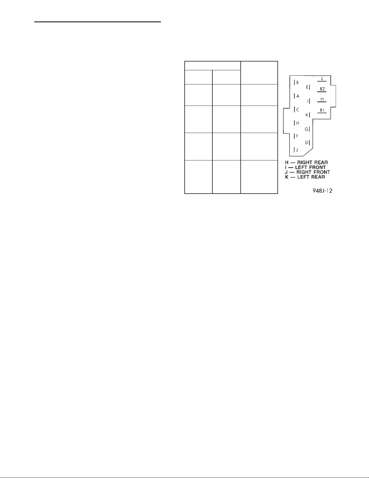
shown in the Multi-Function Switch Continuity chart
(Fig. 3).
SWITCH POSITION CONTINUITY
TURN
SIGNAL
NEUTRAL OFF F and H
LEFT OFF F and H
RIGHT OFF F and K
NEUTRAL ON B and E
HAZARD
WARNING
BETWEEN
F and K
A and E
C and K
C and I
A and E
C and H
C and J
A and E
C and H
C and K
C and I
C and J
Fig. 3 Multi-Function Switch Continuity
(3) If the turn signal switch or hazard warning
switch fails any of the continuity checks, replace the
faulty multi-function switch assembly as required. If
the switch circuits are OK, repair the lighting circuits as required.
TURN SIGNAL SWITCH AND HAZARD
WARNING SWITCH
The turn signal switch and the hazard warning
switch are integral to the multi-function switch.
Refer to Turn Signal and Hazard Warning Sys-
tems in the Diagnosis and Testing section of this
group before testing the multi-function switch. For
complete circuit diagrams, refer to Turn Signals in
the Contents of Group 8W - Wiring Diagrams.
WARNING: ON VEHICLES EQUIPPED WITH AIRBAGS, REFER TO GROUP 8M - PASSIVE RESTRAINT
SYSTEMS BEFORE ATTEMPTING ANY STEERING
WHEEL, STEERING COLUMN, OR INSTRUMENT
PANEL COMPONENT DIAGNOSIS OR SERVICE.
FAILURE TO TAKE THE PROPER PRECAUTIONS
COULD RESULT IN ACCIDENTAL AIRBAG DEPLOYMENT AND POSSIBLE PERSONAL INJURY.
(1) Disconnect and isolate the battery negative
cable. Disconnect the instrument panel wire harness
connector from the multi-function switch connector
receptacle.
(2) Using an ohmmeter, perform the switch continuity checks at the connector receptacle terminals as
REMOVAL AND INSTALLATION
COMBINATION FLASHER
WARNING: ON VEHICLES EQUIPPED WITH AIRBAGS, REFER TO GROUP 8M - PASSIVE
RESTRAINT SYSTEMS BEFORE ATTEMPTING ANY
STEERING WHEEL, STEERING COLUMN, OR
INSTRUMENT PANEL COMPONENT DIAGNOSIS OR
SERVICE. FAILURE TO TAKE THE PROPER PRECAUTIONS COULD RESULT IN ACCIDENTAL AIRBAG DEPLOYMENT AND POSSIBLE PERSONAL
INJURY.
REMOVAL
(1) Disconnect and isolate the battery negative
cable.
(2) Remove the knee blocker from the instrument
panel. Refer to Knee Blocker in the Removal and
Installation section of Group 8E - Instrument Panel
Systems for the procedures.
(3) Reach through the outboard side of the steering column opening to access and disengage the combination flasher wire harness connector retainer from
Page 6
8J - 6 TURN SIGNAL AND HAZARD WARNING SYSTEMS XJ
REMOVAL AND INSTALLATION (Continued)
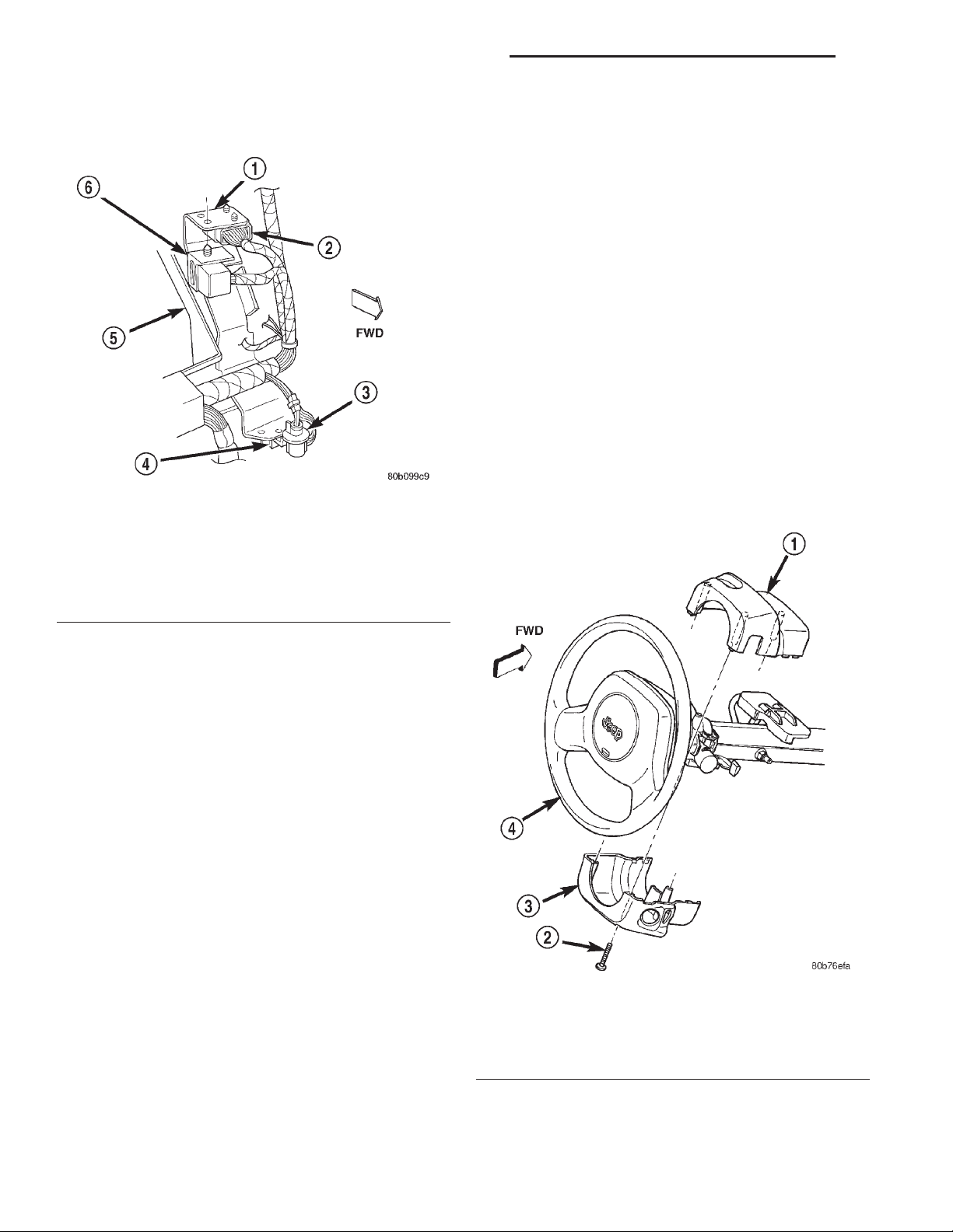
the instrument panel diagnostics mounting bracket
(Fig. 4).
Fig. 4 Combination Flasher Remove/Install
1 – DIAGNOSTICS MOUNTING BRACKET
2 – DIAGNOSTICS SPLICE BLOCK
3 – INSTRUMENT PANEL COURTESY LAMP
4 – DATA LINK CONNECTOR
5 – OUTBOARD STEERING COLUMN OPENING
6 – COMBINATION FLASHER AND CONNECTOR
TURN SIGNAL SWITCH AND HAZARD WARNING SWITCH
WARNING: ON VEHICLES EQUIPPED WITH AIRBAGS, REFER TO GROUP 8M - PASSIVE RESTRAINT
SYSTEMS BEFORE ATTEMPTING ANY STEERING
WHEEL, STEERING COLUMN, OR INSTRUMENT
PANEL COMPONENT DIAGNOSIS OR SERVICE.
FAILURE TO TAKE THE PROPER PRECAUTIONS
COULD RESULT IN ACCIDENTAL AIRBAG DEPLOYMENT AND POSSIBLE PERSONAL INJURY.
REMOVAL
(1) Disconnect and isolate the battery negative
cable.
(2) Remove the knee blocker from the instrument
panel. Refer to Knee Blocker in the Removal and
Installation section of Group 8E - Instrument Panel
Systems for the procedures.
(3) Remove the three screws that secure the lower
steering column shroud to the upper shroud (Fig. 5).
(4) Pull the combination flasher into the instrument panel steering column opening far enough to
access the wire harness connector.
(5) Remove the combination flasher from the wire
harness connector.
(6) Remove the combination flasher from under
the instrument panel.
INSTALLATION
(1) Position the combination flasher under the
instrument panel.
(2) Align the combination flasher terminals with
the terminal cavities in the wire harness connector.
(3) Push in firmly on the combination flasher until
the terminals are fully seated in the terminal cavities
in the wire harness connector.
(4) Install the combination flasher wire harness
connector retainer into the mounting hole of the
instrument panel diagnostics mounting bracket.
(5) Install the knee blocker onto the instrument
panel. Refer to Knee Blocker in the Removal and
Installation section of Group 8E - Instrument Panel
Systems for the procedures.
(6) Reconnect the battery negative cable.
Fig. 5 Steering Column Shrouds Remove/Install
1 – UPPER SHROUD
2 – SCREW (3)
3 – LOWER SHROUD
4 – STEERING WHEEL
(4) If the vehicle is equipped with a standard nontilt steering column, loosen the two upper steering
column mounting nuts. If the vehicle is equipped
Page 7
XJ TURN SIGNAL AND HAZARD WARNING SYSTEMS 8J - 7
REMOVAL AND INSTALLATION (Continued)
with the optional tilt steering column, move the tilt
steering column to the fully lowered position.
(5) Remove both the upper and lower shrouds from
the steering column.
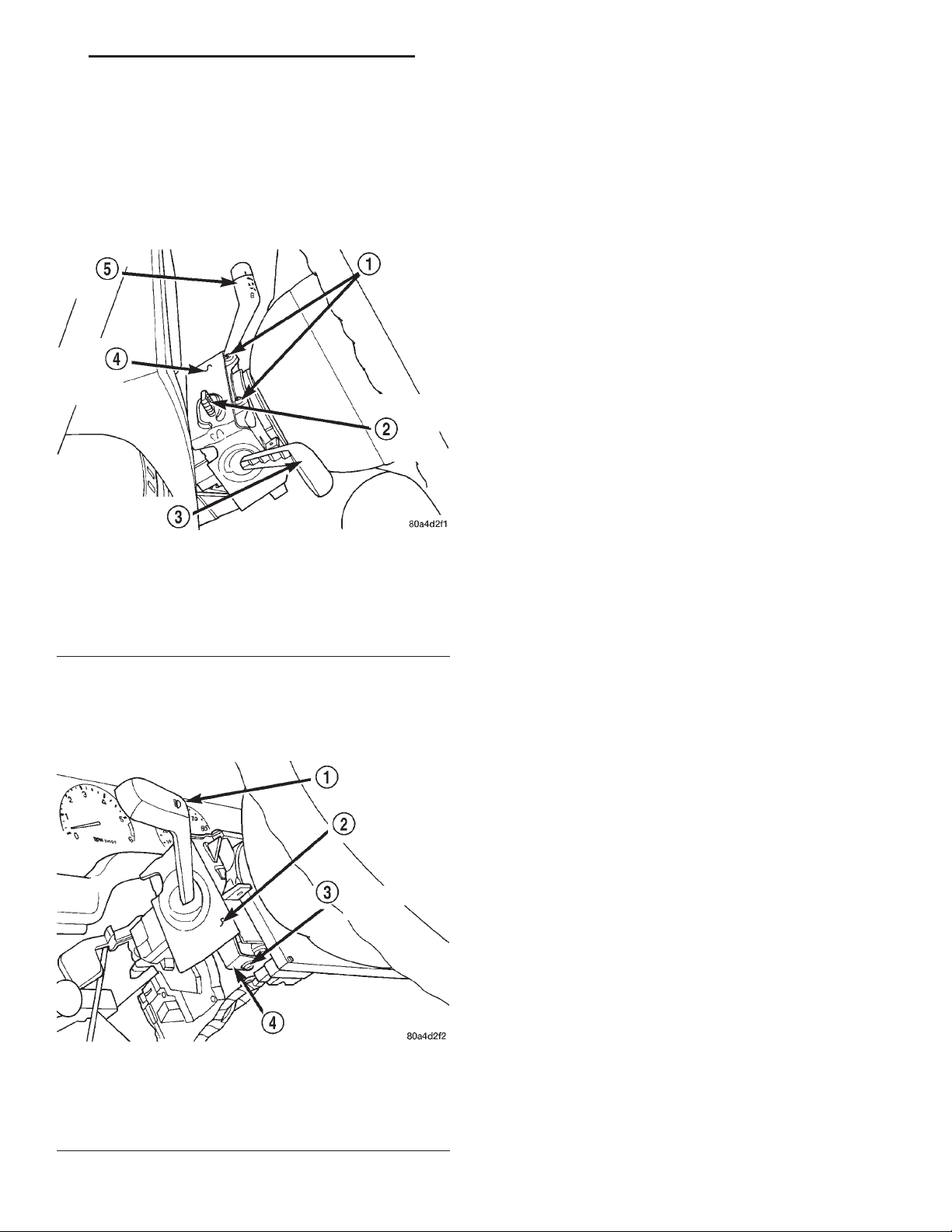
(6) Remove the two screws that secure the multifunction switch water shield and bracket to the top of
the steering column (Fig. 6).
Fig. 6 Water Shield Upper Screws Remove/Install
1 – MOUNTING SCREWS
2 – HAZARD WARNING SWITCH KNOB
3 – MULTI-FUNCTION SWITCH LEVER
4 – WATER SHIELD AND BRACKET
5 – WIPER SWITCH LEVER
(7) Remove the one screw located below the multifunction switch control stalk that secures the multifunction switch water shield and bracket to the
steering column (Fig. 7).
Fig. 7 Water Shield Lower Screw Remove/Install
1 – MULTI-FUNCTION SWITCH LEVER
2 – WATER SHIELD AND BRACKET
3 – LOWER MOUNTING SCREW
4 – LOWER MOUNTING TAB
(8) Gently pull the lower mounting tab of the
multi-function switch water shield bracket away from
the steering column far enough to clear the screw
boss below the multi-function switch control stalk.
(9) Lift the water shield and bracket with the
multi-function switch off of the left side of the steering column far enough to access the two multi-function switch wire harness connectors. If the vehicle is
equipped with the optional tilt steering column, lifting gently upward on the tilt release lever will provide additional clearance to ease multi-function
switch removal.
(10) Disconnect the two instrument panel wire
harness connectors from the multi-function switch
connector receptacles.
(11) Remove the multi-function switch and water
shield from the steering column as a unit.
(12) Gently and carefully remove the water shield
from the switch by pulling it over the hazard warning switch button and the multi-function switch control stalk.
INSTALLATION
(1) Gently and carefully install the water shield
onto the switch by pulling it over the hazard warning
switch button and the multi-function switch control
stalk.
(2) Position the multi-function switch and water
shield near its mounts on the steering column as a
unit.
(3) Reconnect the two instrument panel wire harness connectors to the multi-function switch connector receptacles.
(4) Position the multi-function switch onto its
mounts on the left side of the steering column. If the
vehicle is equipped with the optional tilt steering column, lifting gently upward on the tilt release lever
will provide additional clearance to ease multi-function switch installation.
(5) Position the lower mounting tab of the multifunction switch water shield bracket to the steering
column screw boss below the multi-function switch
control stalk.
(6) Install and tighten the one screw located below
the multi-function switch control stalk that secures
the multi-function switch water shield and bracket to
the steering column. Tighten the screw to 1.1 N·m
(10 in. lbs.).
(7) Install and tighten the two screws that secure
the multi-function switch water shield and bracket to
the top of the steering column. Tighten the screws to
2.2 N·m (20 in. lbs.).
(8) Position both the upper and lower shrouds onto
the steering column.
Page 8

8J - 8 TURN SIGNAL AND HAZARD WARNING SYSTEMS XJ
REMOVAL AND INSTALLATION (Continued)
(9) Install and tighten the three screws that secure
the lower steering column shroud to the upper
shroud. Tighten the screws to 2 N·m (18 in. lbs.).
(10) If the vehicle is so equipped, tighten the two
nuts that secure the non-tilt steering column upper
mounting bracket to the dash panel steering column
support bracket studs. Tighten the nuts to 22 N·m
(200 in. lbs.).
(11) Install the knee blocker onto the instrument
panel. Refer to Knee Blocker in the Removal and
Installation section of Group 8E - Instrument Panel
Systems for the procedures.
(12) Reconnect the battery negative cable.
 Loading...