

Page 1

XJ CHARGING SYSTEM 8C - 1
CHARGING SYSTEM
TABLE OF CONTENTS
page page
DESCRIPTION AND OPERATION
CHARGING SYSTEM.......................1
GENERATOR.............................1
BATTERY TEMPERATURE SENSOR...........2
ELECTRONIC VOLTAGE REGULATOR..........2
DIAGNOSIS AND TESTING
CHARGING SYSTEM.......................2
ON-BOARD DIAGNOSTIC TEST FOR
CHARGING SYSTEM .....................3
DESCRIPTION AND OPERATION
CHARGING SYSTEM
DESCRIPTION
The charging system consists of:
• Generator
• Electronic Voltage Regulator (EVR) circuitry
within the Powertrain Control Module (PCM)
• Ignition switch (refer to Group 8D, Ignition Sys-
tem for information)
• Battery (refer to Group 8A, Battery for informa-
tion)
• Battery temperature sensor
• Generator Lamp (if equipped)
• Check Gauges Lamp (if equipped)
• Voltmeter (refer to Group 8E, Instrument Panel
and Gauges for information)
• Wiring harness and connections (refer to Group
8W, Wiring for information)
OPERATION
The charging system is turned on and off with the
ignition switch. The system is on when the engine is
running and the ASD relay is energized. When the
ASD relay is on, voltage is supplied to the ASD relay
sense circuit at the PCM. This voltage is connected
through the PCM and supplied to one of the generator field terminals (Gen. Source +) at the back of the
generator.
The amount of DC current produced by the generator is controlled by the EVR (field control) circuitry
contained within the PCM. This circuitry is connected in series with the second rotor field terminal
and ground.
A battery temperature sensor, located in the battery tray housing, is used to sense battery tempera-
REMOVAL AND INSTALLATION
GENERATOR.............................3
BATTERY TEMPERATURE SENSOR ...........5
SPECIFICATIONS
GENERATOR RATINGS.....................5
TORQUE CHART..........................5
ture. This temperature data, along with data from
monitored line voltage, is used by the PCM to vary
the battery charging rate. This is done by cycling the
ground path to control the strength of the rotor magnetic field. The PCM then compensates and regulates
generator current output accordingly.
All vehicles are equipped with On-Board Diagnostics (OBD). All OBD-sensed systems, including EVR
(field control) circuitry, are monitored by the PCM.
Each monitored circuit is assigned a Diagnostic Trouble Code (DTC). The PCM will store a DTC in electronic memory for certain failures it detects. Refer to
On-Board Diagnostics in Group 25, Emission Control
System for more DTC information.
The Check Gauges Lamp (if equipped) monitors:
charging system voltage, engine coolant temperature and engine oil pressure. If an extreme condition
is indicated, the lamp will be illuminated. This is
done as reminder to check the three gauges. The signal to activate the lamp is sent via the CCD bus circuits. The lamp is located on the instrument panel.
Refer to Group 8E, Instrument Panel and Gauges for
additional information.
GENERATOR
DESCRIPTION
The generator is belt-driven by the engine using a
serpentine type drive belt. It is serviced only as a
complete assembly. If the generator fails for any reason, the entire assembly must be replaced.
OPERATION
As the energized rotor begins to rotate within the
generator, the spinning magnetic field induces a current into the windings of the stator coil. Once the
Page 2

8C - 2 CHARGING SYSTEM XJ
DESCRIPTION AND OPERATION (Continued)
generator begins producing sufficient current, it also
provides the current needed to energize the rotor.
The Y type stator winding connections deliver the
induced AC current to 3 positive and 3 negative
diodes for rectification. From the diodes, rectified DC
current is delivered to the vehicle electrical system
through the generator battery terminal.
Although the generators appear the same externally, different generators with different output ratings are used on this vehicle. Be certain that the
replacement generator has the same output rating
and part number as the original unit. Refer to Generator Ratings in the Specifications section at the
back of this group for amperage ratings and part
numbers.
Noise emitting from the generator may be caused
by: worn, loose or defective bearings; a loose or defective drive pulley; incorrect, worn, damaged or misadjusted fan drive belt; loose mounting bolts; a
misaligned drive pulley or a defective stator or diode.
BATTERY TEMPERATURE SENSOR
DESCRIPTION
The Battery Temperature Sensor (BTS) is attached
to the battery tray located under the battery.
OPERATION
The amount of DC current produced by the generator is controlled by EVR circuitry contained within
the PCM. This circuitry is connected in series with
the generators second rotor field terminal and its
ground.
Voltage is regulated by cycling the ground path to
control the strength of the rotor magnetic field. The
EVR circuitry monitors system line voltage (B+) and
battery temperature (refer to Battery Temperature
Sensor for more information). It then determines a
target charging voltage. If sensed battery voltage is
0.5 volts or lower than the target voltage, the PCM
grounds the field winding until sensed battery voltage is 0.5 volts above target voltage. A circuit in the
PCM cycles the ground side of the generator field up
to 100 times per second (100Hz), but has the capability to ground the field control wire 100% of the time
(full field) to achieve the target voltage. If the charging rate cannot be monitored (limp-in), a duty cycle
of 25% is used by the PCM in order to have some
generator output. Also refer to Charging System
Operation for additional information.
DIAGNOSIS AND TESTING
OPERATION
The BTS is used to determine the battery temperature and control battery charging rate. This temperature data, along with data from monitored line
voltage, is used by the PCM to vary the battery
charging rate. System voltage will be higher at colder
temperatures and is gradually reduced at warmer
temperatures.
The PCM sends 5 volts to the sensor and is
grounded through the sensor return line. As temperature increases, resistance in the sensor decreases
and the detection voltage at the PCM increases.
The BTS is also used for OBD II diagnostics. Certain faults and OBD II monitors are either enabled
or disabled, depending upon BTS input (for example,
disable purge and enable Leak Detection Pump
(LDP) and O2 sensor heater tests). Most OBD II
monitors are disabled below 20°F.
ELECTRONIC VOLTAGE REGULATOR
DESCRIPTION
The Electronic Voltage Regulator (EVR) is not a
separate component. It is actually a voltage regulating circuit located within the Powertrain Control
Module (PCM). The EVR is not serviced separately. If
replacement is necessary, the PCM must be replaced.
CHARGING SYSTEM
The following procedures may be used to diagnose
the charging system if:
• the generator lamp (if equipped) is illuminated
with the engine running
• the voltmeter (if equipped) does not register
properly
• an undercharged or overcharged battery condi-
tion occurs.
Remember that an undercharged battery is often
caused by:
• accessories being left on with the engine not
running
• a faulty or improperly adjusted switch that
allows a lamp to stay on. See Ignition-Off Draw Test
in Group 8A, Battery for more information.
INSPECTION
To perform a complete test of the charging system,
refer to the appropriate Powertrain Diagnostic Procedures service manual and the DRB scan tool. Perform the following inspections before attaching the
scan tool.
(1) Inspect the battery condition. Refer to Group
8A, Battery for procedures.
(2) Inspect condition of battery cable terminals,
battery posts, connections at engine block, starter
solenoid and relay. They should be clean and tight.
Repair as required.
Page 3
XJ CHARGING SYSTEM 8C - 3
DIAGNOSIS AND TESTING (Continued)
(3) Inspect all fuses in both the fuseblock and
Power Distribution Center (PDC) for tightness in
receptacles. They should be properly installed and
tight. Repair or replace as required.
(4) Inspect generator mounting bolts for tightness.
Replace or tighten bolts if required. Refer to the Generator Removal/Installation section of this group for
torque specifications.
(5) Inspect generator drive belt condition and tension. Tighten or replace belt as required. Refer to
Belt Tension Specifications in Group 7, Cooling System.
(6) Inspect automatic belt tensioner (if equipped).
Refer to Group 7, Cooling System for information.
(7) Inspect generator electrical connections at generator field, battery output, and ground terminal (if
equipped). Also check generator ground wire connection at engine (if equipped). They should all be clean
and tight. Repair as required.
ON-BOARD DIAGNOSTIC TEST FOR CHARGING SYSTEM
The Powertrain Control Module (PCM) monitors
critical input and output circuits of the charging system, making sure they are operational. A Diagnostic
Trouble Code (DTC) is assigned to each input and
output circuit monitored by the On-Board Diagnostic
(OBD) system. Some circuits are checked continuously and some are checked only under certain conditions.
For DTC information, refer to Diagnostic Trouble
Codes in Group 25, Emission Control System. This
will include a complete list of DTC’s including DTC’s
for the charging system.
(1) Disconnect negative battery cable at battery.
(2) Remove generator drive belt. Refer to Group 7,
Cooling System for procedures.
(3) Left Hand Drive (LHD) Vehicles Only: Remove
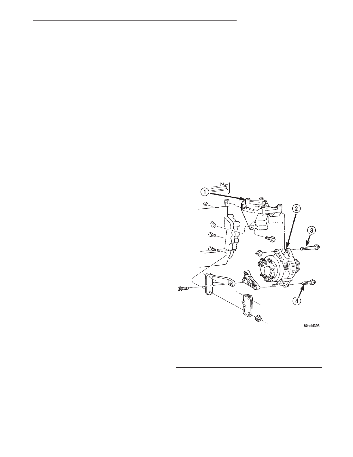
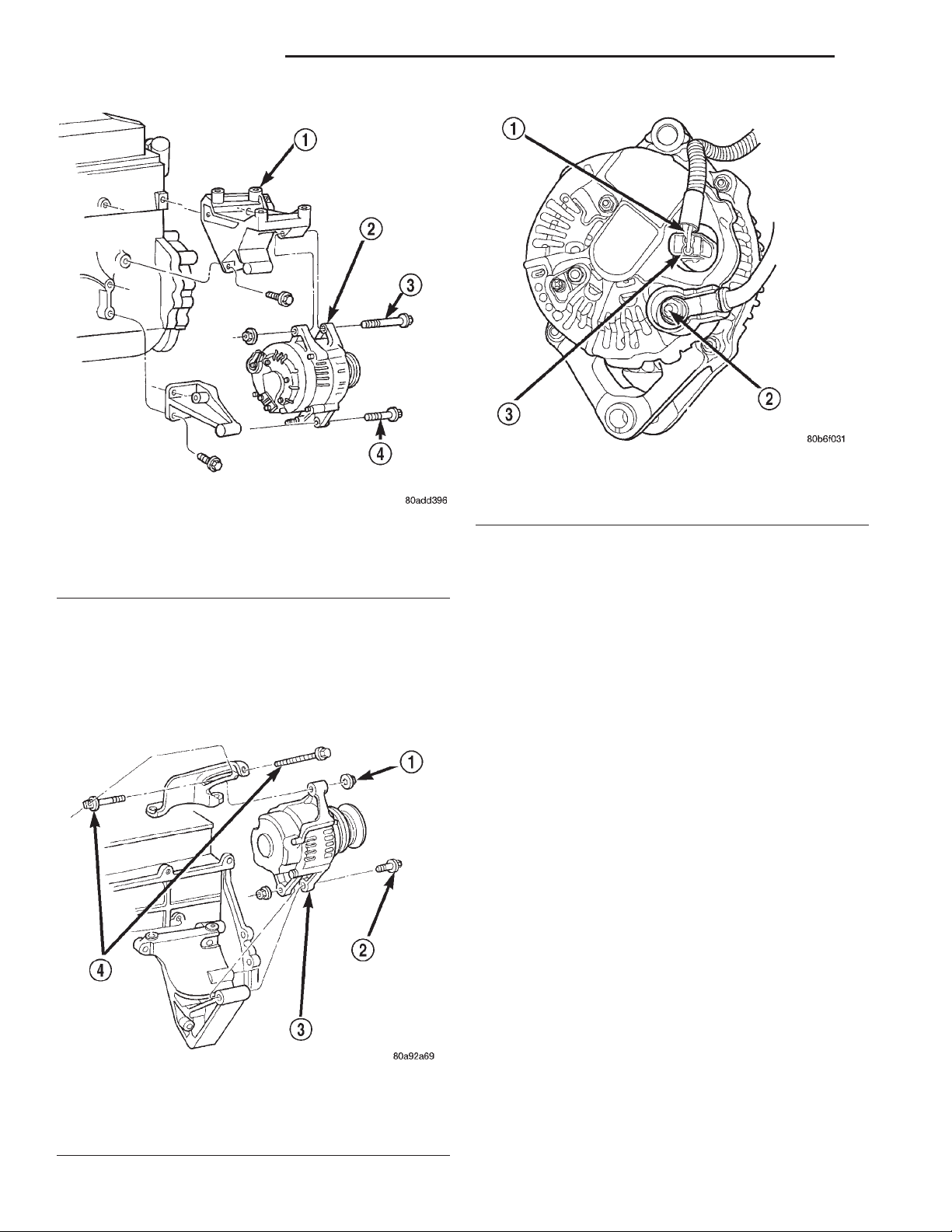
generator pivot and mounting bolts/nut (Fig. 1) or
(Fig. 2). Position generator for access to wire connectors.
(4) Right Hand Drive (RHD) Vehicles Only:
Remove upper nut (generator adjustment nut) and
both belt adjustment bolts (Fig. 3). Remove generator
lower nut/bolt. Position generator for access to wire
connectors.
(5) If equipped, unsnap plastic cover from B+ terminal.
(6) Remove B+ terminal mounting nut at rear of
generator (Fig. 4). Disconnect terminal from generator.
(7) Disconnect field wire connector at rear of generator by pushing on connector tab.
(8) Remove generator from vehicle.
REMOVAL AND INSTALLATION
GENERATOR
REMOVAL
WARNING: DISCONNECT NEGATIVE CABLE FROM
BATTERY BEFORE REMOVING BATTERY OUTPUT
WIRE (B+ WIRE) FROM GENERATOR. FAILURE TO
DO SO CAN RESULT IN INJURY OR DAMAGE TO
ELECTRICAL SYSTEM.
Fig. 1 Remove/Install Generator—2.5L Engine
1 – UPPER MOUNTING BRACKET
2 – GENERATOR
3 – UPPER BOLT
4 – LOWER BOLT
Page 4
8C - 4 CHARGING SYSTEM XJ
REMOVAL AND INSTALLATION (Continued)
Fig. 4 Generator Connectors—Typical Denso
1 – FIELD WIRES
2 – B+ (OUTPUT TERMINAL)
Fig. 2 Remove/Install Generator—4.0L Engine—LHD
1 – UPPER MOUNTING BRACKET
2 – GENERATOR
3 – UPPER BOLT
4 – LOWER BOLT
INSTALLATION
(1) Position generator to engine and snap field
wire connector into rear of generator.
(2) Install B+ terminal to generator mounting
stud. Tighten mounting nut to 8.5 N·m (75 in. lbs.)
torque.
3 – FIELD WIRE CONNECTOR
(3) If equipped, snap plastic cover to B+ terminal.
(4) LHD Vehicles: Install generator fasteners and
tighten as follows:
• Generator upper mounting bolt-55 N·m (41 ft.
lbs.) torque.
• Generator lower pivot bolt/nut-55 N·m (41 ft.
lbs.) torque.
CAUTION: Never force a belt over a pulley rim
using a screwdriver. The synthetic fiber of the belt
can be damaged.
Fig. 3 Remove/Install Generator—4.0L Engine—RHD
1 – UPPER NUT
2 – LOWER BOLT
3 – GENERATOR
4 – BELTADJUSTMENT BOLTS
CAUTION: When installing a serpentine accessory
drive belt, the belt MUST be routed correctly. The
water pump will be rotating in the wrong direction if
the belt is installed incorrectly, causing the engine
to overheat. Refer to belt routing label in engine
compartment, or refer to Belt Schematics in Group
7, Cooling System.
(5) LHD Vehicles: Install generator drive belt.
Refer to Group 7, Cooling System for procedures.
(6) RHD Vehicles: Install upper nut (generator
adjustment nut) and both belt adjustment bolts.
Install generator lower nut/bolt.
(7) RHD Vehicles: On vehicles equipped with RHD,
the generator is used to adjust the serpentine belt.
Refer to Group 7, Cooling System for belt routing,
belt adjustment and bolt tightening procedures.
(8) Install negative battery cable to battery.
Page 5
XJ CHARGING SYSTEM 8C - 5
REMOVAL AND INSTALLATION (Continued)
BATTERY TEMPERATURE SENSOR
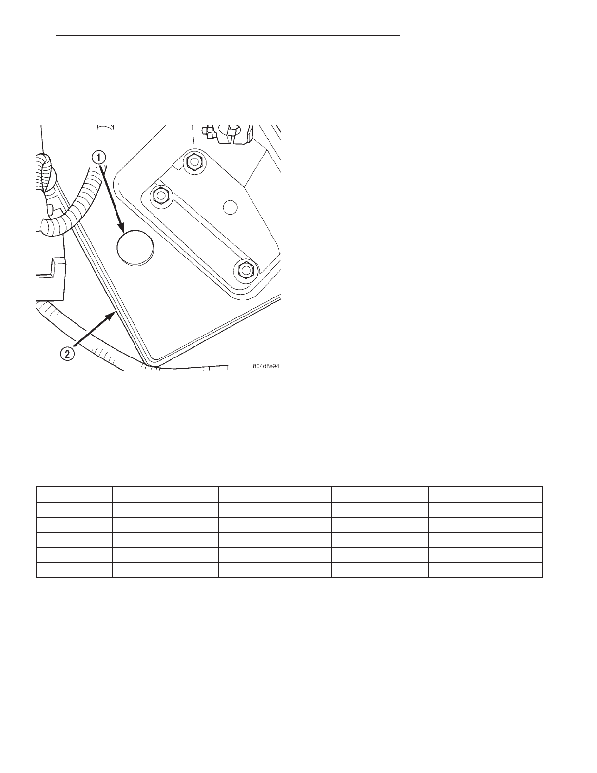
The battery temperature sensor is located under
vehicle battery (Fig. 5) and is attached to a mounting
hole on battery tray.
REMOVAL
(1) Remove battery. Refer to Group 8A, Battery for
procedures.
(2) Disconnect sensor pigtail harness from engine
wire harness.
(3) Pry sensor straight up from battery tray
mounting hole.
INSTALLATION
(1) Feed pigtail harness through hole in top of bat-
tery tray and press sensor into top of battery tray.
(2) Connect pigtail harness.
(3) Install battery. Refer to Group 8A, Battery for
procedures.
Fig. 5 Battery Temperature Sensor
1 – BATTERY TEMPERATURE SENSOR
2 – BATTERY TRAY
SPECIFICATIONS
GENERATOR RATINGS
TYPE PART NUMBER RATED SAE AMPS ENGINES MINIMUM TEST AMPS
DENSO 56041685AA 117 4.0L 88
DENSO 56041565AA 81 4.0L 57
DENSO 56005684AB 81 2.5L 57
DENSO 56005685AC 117 2.5L 88
DENSO 56041822AA 124 2.5L/4.0L 90
TORQUE CHART
Right Hand Drive= RHD, Left Hand Drive= LHD.
Description Torque
Generator Mounting Bolt—LHD—2.5L/4.0L
Engine .................. 55N·m(41ft.lbs.)
Generator Pivot Bolt/Nut—LHD—2.5L/4.0L
Engine .................. 55N·m(41ft.lbs.)
Battery Terminal Nut—LHD or
RHD .................. 8.5N·m(75in.lbs.)
Description Torque
Ground Terminal Nut—LHD or
RHD .................. 8.5N·m(75in.lbs.)
Harness Hold-down Nut—LHD or
RHD .................. 8.5N·m(75in.lbs.)
Field Terminal Nuts—LHD or
RHD .................. 2.8N·m(25in.lbs.)
Page 6

 Loading...