

Page 1
XJ STARTING SYSTEMS 8B - 1
STARTING SYSTEMS
TABLE OF CONTENTS
page page
REMOVAL AND INSTALLATION
STARTER — LHD (DIESEL).................1
STARTER — RHD (DIESEL).................2
STARTER RELAY .........................3
REMOVAL AND INSTALLATION
STARTER — LHD (DIESEL)
Removal
(1) Disconnect the negative battery cable.
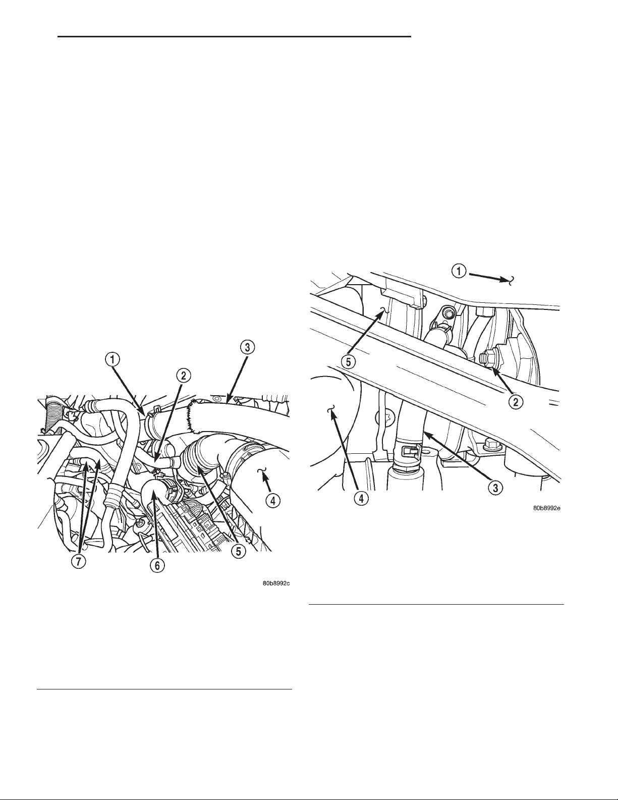
(2) Remove the innercooler inlet hose from turbo-
charger and position it out of the way (Fig. 1).
SPECIFICATIONS
STARTING SYSTEM .......................3
TORQUE SPECIFICATIONS..................4
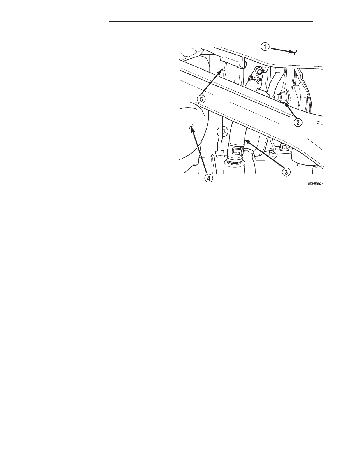
(5) Remove the turbocharger oil return hose from
engine block and plug (Fig. 2).
Fig. 1 LHD Engine Compartment — Diesel
1 – INTAKE MANIFOLD ELBOW
2 – BREATHER HOSE
3 – INNERCOOLER OUTLET HOSE
4 – AIR FILTER COVER
5 – AIR FILTER OUTLET (FRESH AIR) HOSE
6 – INNERCOOLER INLET HOSE
7 – HEATER CORE COOLANT SUPPLY HOSES
(3) Remove the (2) right engine mount upper sill
plate nuts.
(4) Raise the vehicle on a hoist.
Fig. 2 Turbocharger Oil Return Hose — Position &
Orientation
1 – VEHICLE UNDERBODY
2 – RIGHT ENGINE MOUNT THROUGHBOLT NUT
3 – TURBOCHARGER OIL RETURN HOSE
4 – EXHAUST MANIFOLD DOWNPIPE
5 – TURBOCHARGER
(6) Remove the right engine mount through bolt
nut only (Fig. 2). Do not remove the bolt at this time.
(7) Position a jack stand and raise the weight off
the right engine mount.
(8) Remove the (2) right engine mount lower sill
plate bolts.
(9) Remove the (4) right engine mount bracket to
engine block retaining bolts.
(10) Remove the engine mount throughbolt.
(11) Remove the engine mount and the engine
mount bracket from the vehicle.
Page 2
8B - 2 STARTING SYSTEMS XJ
REMOVAL AND INSTALLATION (Continued)
(12) Remove the starter motor support bracket.
(13) Disconnect the starter motor electrical connec-
tors.
CAUTION: Heatshields are very sharp. Wear gloves
to prevent injury.
(14) Remove the starter heatshield.
(15) Remove the (3) starter motor retaining bolts.
(16) Remove the starter motor from the vehicle.
Installation
(1) Position the starter motor and install retaining
bolts. Torque bolts to 27 N·m (20 ft. lbs.).
(2) Connect the starter motor electrical. Torque
(B+) nut to 27 N·m (20 ft. lbs.).
CAUTION: Heatshields are very sharp. Wear gloves
to prevent injury.
(3) Install the starter heatshield.
(4) Install the starter motor support bracket.
Torque nuts to 10 N·m (90 in. lbs.).
(5) Install the engine mount and engine mount
bracket in the vehicle, making sure sill plate studs
are through engine mount.
(6) Install the engine mount throughbolt and nut
leaving them loose at this time.
(7) Install the (4) engine mount bracket to engine
block bolts. Torque bolts to 61 N·m (45 ft. lbs.).
(8) Tighten, but do not torque (2) right engine
mount lower bolts.
(9) Remove the jack stand.
(10) Torque the (2) lower engine mount bolts to 54
N·m (40 ft. lbs.).
(11) Torque throughbolt nut to 65 N·m (48 ft. lbs.).
(12) Install the oil return line on the engine block
nipple.
(13) Lower the vehicle from the hoist.
(14) Install the (2) engine mount upper sill plate
nuts. Torque nuts to 41 N·m (30 ft. lbs.).
(15) Install the innercooler inlet hose on turbocharger.
(16) Connect the negative battery cable.
STARTER — RHD (DIESEL)
1 – VEHICLE UNDERBODY
2 – RIGHT ENGINE MOUNT THROUGHBOLT NUT
3 – TURBOCHARGER OIL RETURN HOSE
4 – EXHAUST MANIFOLD DOWNPIPE
5 – TURBOCHARGER
(6) Remove the right engine mount through bolt
nut only (Fig. 3). Do not remove the bolt at this time.
(7) Remove the engine mount upper sill plate nuts.
(8) Position a jack stand and raise weight off right
engine mount.
(9) Remove the track bar support bracket retain-
ing bolts and remove bracket.
(10) Remove the remaining lower engine mount
bolt from the sill plate.
(11) Remove the (4) engine mount bracket bolts.
(12) Remove the engine mount throughbolt.
(13) Remove the engine mount and engine mount
bracket from the vehicle.
(14) Remove the starter motor support bracket.
CAUTION: Heatshield is very sharp. Wear gloves to
prevent injury.
Fig. 3 Turbocharger Oil Return Line
REMOVAL
(1) Disconnect the negative battery cable.
(2) Make sure steering wheel is in the unlocked
position.
(3) Raise the vehicle on a hoist.
(4) Rotate the front wheels to access and remove
the steering shaft pinch bolt, slide shaft straight off
gearbox input shaft and position steering shaft aside.
(5) Remove the turbocharger oil return line from
engine block and plug (Fig. 3).
(15) Remove the starter heat shield.
(16) Disconnect the starter motor electrical connec-
tors.
(17) Remove the (3) stater motor retaining bolts.
(18) Remove the starter motor from the vehicle.
Installation
(1) Position the starter motor. Torque retaining
bolts to 27 N·m (20 ft. lbs.).
Page 3

XJ STARTING SYSTEMS 8B - 3
REMOVAL AND INSTALLATION (Continued)
(2) Reconnect the starter motor electrical. Torque
(B+) nut to 27 N·m (20 ft. lbs.).
CAUTION: Heatshield is very sharp. Wear gloves to
prevent injury.
(3) Install the starter heat shield.
(4) Install the starter motor support bracket.
Torque bolt to 47 N·m (35 ft. lbs.). Torque nuts to 10
N·m (90 in. lbs.).
(5) Install the engine mount and engine mount
bracket in the vehicle.
(6) Install the engine mount throughbolt and nut
leaving them loose at this time.
(7) Install, but do not torque the engine mount
and track bar support bracket bolts
(8) Install the (4) engine mount bracket to engine
block bolts. Torque bolts to 61 N·m (45 ft. lbs.).
(9) Remove the jack stand.
(10) Install and torque the upper engine mount sill
plate nuts to 41 N·m (30 ft. lbs.).
(11) Torque the lower engine mount retaining bolts
to 54 N·m (40 ft. lbs.).
(12) Torque the larger track bar support bracket
bolts to 125 N·m (92 ft. lbs.).
(13) Torque the engine mount throughbolt nut to
65 N·m (48 ft. lbs.).
(14) Install the oil return line on the engine block
nipple.
(15) Install steering shaft pinch bolt. Torque to 49
N·m (36 ft. lbs.).
(16) Lower the vehicle from the hoist.
(17) Connect the negative battery cable.
STARTER RELAY
(1) Disconnect and isolate the battery negative
cable.
(2) Remove the cover from the Power Distribution
Center (PDC).
(3) Refer to the label on the PDC for starter relay
identification and location.
(4) Unplug the starter relay from the PDC.
(5) Install the starter relay by aligning the relay
terminals with the cavities in the PDC and pushing
the relay firmly into place.
(6) Install the PDC cover.
(7) Connect the battery negative cable.
(8) Test the relay operation.
Page 4
8B - 4 STARTING SYSTEMS XJ
SPECIFICATIONS
STARTING SYSTEM
Starter and Solenoid
Engine Application 2.5L Diesel
Power Rating 2.2 Kilowatt
Voltage 12 Volts
Number of Fields 4
Number of Poles 4
Number of Brushes 4
Drive Type Planetary Gear Reduction
Free Running Test Voltage 11.5 Volts
Free Running Test Maximum
Amperage Draw
Free Running Test Minimum
Speed
Solenoid Closing Maximum
Voltage
*Cranking Amperage Draw
test
*Test at operating temperature. Cold engine, tight (new) engine, or heavy oil will
increase starter amperage draw.
160 Amperes
5500 rpm
7.8 Volts
350 Amperes
TORQUE SPECIFICATIONS
DESCRIPTION TORQUE
Engine Mount Throughbolt .... 65N·m(48ft.lbs.)
Engine Mount Upper Sill Plate Nuts ..... 41N·m
(30 ft. lbs.)
Engine Mount to Engine Mounting Bolts . . 61 N·m
(45 ft. lbs.)
Lower Engine Mount Bolts .... 54N·m(40ft.lbs.)
Stater Motor (B+) Terminal .... 27N·m(20ft.lbs.)
Starter Motor Retaining Bolts . . 27 N·m (20 ft. lbs.)
Starter Motor Support Bracket Nuts ...... 10N·m
(90 in. lbs.)
Steering Shaft Pinch Bolt ..... 49N·m(36ft.lbs.)
Track Bar Support Bracket Bolts ....... 125N·m
(92 ft. lbs.)
 Loading...