

Page 1

XJ STARTING SYSTEMS 8B - 1
STARTING SYSTEMS
TABLE OF CONTENTS
page page
DESCRIPTION AND OPERATION
STARTING SYSTEM .......................1
STARTER MOTOR.........................2
STARTER RELAY .........................3
DIAGNOSIS AND TESTING
STARTING SYSTEM .......................4
STARTER MOTOR NOISE - 2.5L ENGINE ......8
STARTER MOTOR.........................9
DESCRIPTION AND OPERATION
STARTING SYSTEM
DESCRIPTION
An electrically operated engine starting system is
standard factory-installed equipment on this model.
The starting system is designed to provide the vehicle operator with a convenient, efficient and reliable
means of cranking and starting the internal combustion engine used to power the vehicle and all of its
accessory systems. The starting system includes the
following major components:
• Battery
• Battery cables
• Clutch pedal position switch (manual transmis-
sion)
• Ignition switch
• Park/neutral position switch (automatic trans-
mission)
• Starter motor (including the integral starter
solenoid)
• Starter relay.
The starting system consists of two separate circuits. A high-amperage feed circuit that feeds the
starter motor between 150 and 350 amperes of battery current, and a low-amperage control circuit that
operates on less than 20 amperes of battery current.
The starting system high-amperage feed circuit
includes the battery, the battery cables, the contact
disc portion of the starter solenoid, and the starter
motor. The following starting system feed circuit
components are covered in more detail in other areas
of this service manual:
• The battery is located in the passenger side
front corner of the engine compartment, near the
upper radiator crossmember and provides the electrical current needed to operate the starting system.
STARTER RELAY ........................10
REMOVAL AND INSTALLATION
STARTER MOTOR........................11
STARTER RELAY ........................13
CLEANING AND INSPECTION
STARTING SYSTEM ......................14
SPECIFICATIONS
STARTING SYSTEM ......................15
Refer to Battery in the index of this service manual
for the location of more information on the battery.
• The battery cables connect the battery to the
electrical system of the vehicle and to the starting
system. Refer to Battery Cables in the index of this
service manual for the location of more information
on the battery cables.
The starting system low-amperage control circuit
includes the ignition switch, the clutch pedal position
switch (manual transmission), the park/neutral position switch (automatic transmission), the starter
relay, the electromagnetic windings of the starter
solenoid, and the wire harnesses that connect these
components. The following starting system control
circuit components are covered in more detail in
other areas of this service manual:
• The ignition switch is mounted on the bottom of
the steering column and actuates the starting system
when a properly coded ignition key is inserted in the
ignition lock cylinder on the right side of the steering
column and turned to the spring-loaded momentary
Start position. Refer to Ignition Switch and Key
Lock Cylinder in the index of this service manual
for the location of more information on the ignition
switch.
• The clutch pedal position switch is integral to
the master cylinder of the clutch hydraulic linkage
assembly on models equipped with a manual transmission. Refer to Clutch Hydraulic Linkage in the
index of this service manual for the location of more
information on the clutch pedal position switch.
• On models with the 2.5L engine, the park/neutral position switch is threaded into the left side of
the automatic transmission case and has a springloaded plunger that is actuated by a cam integral to
the gearshift mechanism within the transmission.
The back up lamp switch is also integral to the park/
neutral position switch. On models with the 4.0L
Page 2
8B - 2 STARTING SYSTEMS XJ
DESCRIPTION AND OPERATION (Continued)
engine, the park/neutral position switch is mounted
on the right side of the automatic transmission case.
The switch is indexed to and driven by the transmission manual valve shaft. Refer to Park/Neutral
Position Switch in the index of this service manual
for the location of more information on either version
of the park/neutral position switch.
Following are general descriptions of the starter
relay and the starter motor. See the owner’s manual
in the vehicle glove box for more information on the
features, use and operation of the starting system.
Refer to Starting System in the index of this service manual for the location of complete wiring diagrams for the starting system.
NOTE: This group covers both Left-Hand Drive
(LHD) and Right-Hand Drive (RHD) versions of this
model. Whenever required and feasible, the RHD
versions of affected vehicle components have been
constructed as mirror-image of the LHD versions.
While most of the illustrations used in this group
represent only the LHD version, the diagnostic and
service procedures outlined can generally be
applied to either version. Exceptions to this rule
have been clearly identified as LHD or RHD, if a
special illustration or procedure is required.
by engaging the starter pinion gear with the starter
ring gear. Once the engine starts, the ignition switch
key is released by the vehicle operator. When the
ignition switch key is released, the switch automatically returns to the On position, which de-energizes
the starting system.
STARTER MOTOR
DESCRIPTION
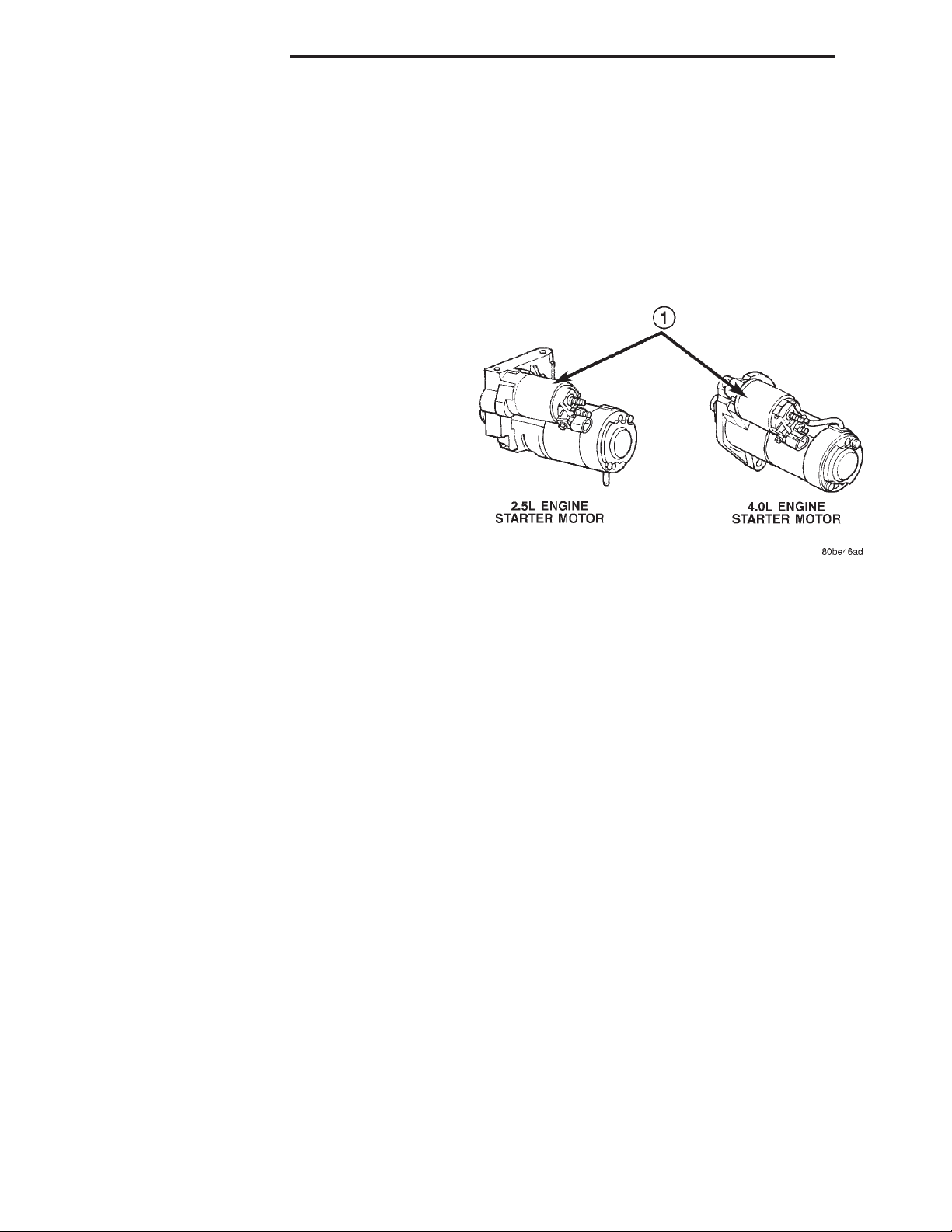
Fig. 1 Starter Motors
1 – STARTER SOLENOID
OPERATION
If the vehicle is equipped with a manual transmission, the clutch pedal position switch is installed in
series between the ignition switch and the coil battery terminal of the starter relay. This normally open
switch prevents the starter relay from being energized when the ignition switch is turned to the
momentary Start position, unless the clutch pedal is
fully depressed. This feature prevents starter motor
operation while the clutch disc and the flywheel are
engaged. The starter relay coil ground terminal is
always grounded on vehicles with a manual transmission.
If the vehicle is equipped with an automatic transmission, battery voltage is supplied through the lowamperage control circuit to the coil battery terminal
of the starter relay when the ignition switch is
turned to the momentary Start position. The park/
neutral position switch is installed in series between
the starter relay coil ground terminal and ground.
This normally open switch prevents the starter relay
from being energized and the starter motor from
operating unless the automatic transmission gear
selector is in the Neutral or Park positions.
When the starter relay coil windings are energized,
the relay directs battery current to the starter solenoid coil windings. When the starter solenoid coil
windings are energized, the solenoid directs battery
current to the starter motor, which cranks the engine
The starter motors used for both the 2.5L and the
4.0L engines available in this model are not interchangeable (Fig. 1). However, each of these starter
motors incorporates several of the same features to
create a reliable, efficient, compact, lightweight and
powerful unit. Both starters feature high torque
direct current electric motors. Inside both starter
motors the commutator of the rotating motor armature is contacted by four brushes. The starter motor
for the 2.5L engine is driven by four permanent magnet field poles, while the starter motor for the 4.0L
engine is driven by four electromagnetic field coils
wound around four pole shoes. The 2.5L starter
motor is rated at 1.2 kilowatts (about 1.6 horsepower) output at 12 volts, while the 4.0L starter
motor is rated at 1.4 kilowatts (about 1.9 horsepower) output at 12 volts.
These starter motors are equipped with a planetary gear reduction (intermediate transmission) system. The planetary gear reduction system consists of
a gear that is integral to the output end of the electric motor armature shaft that is in continual
engagement with a larger gear that fits on a spline
on the input end of the starter pinion gear shaft.
This feature makes it possible to reduce the dimensions of the starter. At the same time, it allows
higher armature rotational speed and delivers
increased torque through the starter pinion gear.
Page 3
XJ STARTING SYSTEMS 8B - 3
DESCRIPTION AND OPERATION (Continued)
Both starter motors use an overrunning clutch and
starter pinion gear unit to engage and drive the
starter ring gear, which is integral to the flywheel
(manual transmission) or torque converter drive
plate (automatic transmission) mounted on the rear
crankshaft flange. Shims are available and can be
used to adjust the 2.5L starter motor mounting position to correct for improper starter pinion gear to
starter ring gear engagement.
The starter motors for both engines are activated
by an integral heavy duty starter solenoid switch
mounted to the overrunning clutch housing. This
electromechanical switch connects and disconnects
the feed of battery current to the starter motor
through a movable contact on one end of the solenoid
core or plunger. At the same time, the solenoid
plunger actuates a shift fork that engages and disengages the starter pinion gear with a starter ring
gear. The starter solenoid has two electromagnetic
windings or coils, a pull-in coil and a hold-in coil. The
pull-in coil requires more battery current and produces a stronger electromagnetic field than the
hold-in coil.
Both starter motors are serviced only as a unit
with their starter solenoids, and cannot be repaired.
If either component is faulty or damaged, the entire
starter motor and starter solenoid unit must be
replaced.
OPERATION
When the starter solenoid pull-in coil windings are
energized the solenoid plunger is drawn into the electromagnetic coil. The solenoid plunger pulls the shift
lever in the starter motor. This engages the starter
overrunning clutch and pinion gear with the starter
ring gear on the manual transmission flywheel or on
the automatic transmission torque converter drive
plate. As the solenoid plunger reaches the end of its
travel, it moves the solenoid contact disc to complete
the high-amperage starter feed circuit and energizes
the solenoid hold-in coil windings. Battery current
now flows between the solenoid battery terminal and
the starter field terminal, energizing the starter and
cranking the engine.
Once the engine starts, the overrunning clutch protects the starter motor from damage by allowing the
starter pinion gear to spin faster than the pinion
shaft. When the solenoid plunger hold-in coil is deenergized, the solenoid plunger return spring returns
the plunger to its relaxed position. This causes the
solenoid contact disc to open the starter feed circuit,
and the shift lever to disengage the overrunning
clutch and pinion gear unit from the starter ring
gear.
STARTER RELAY
DESCRIPTION
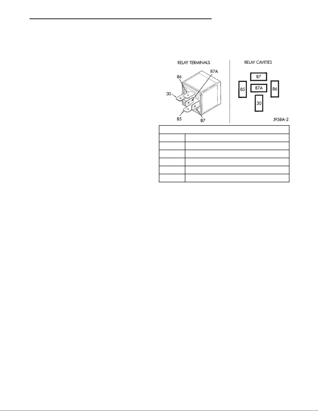
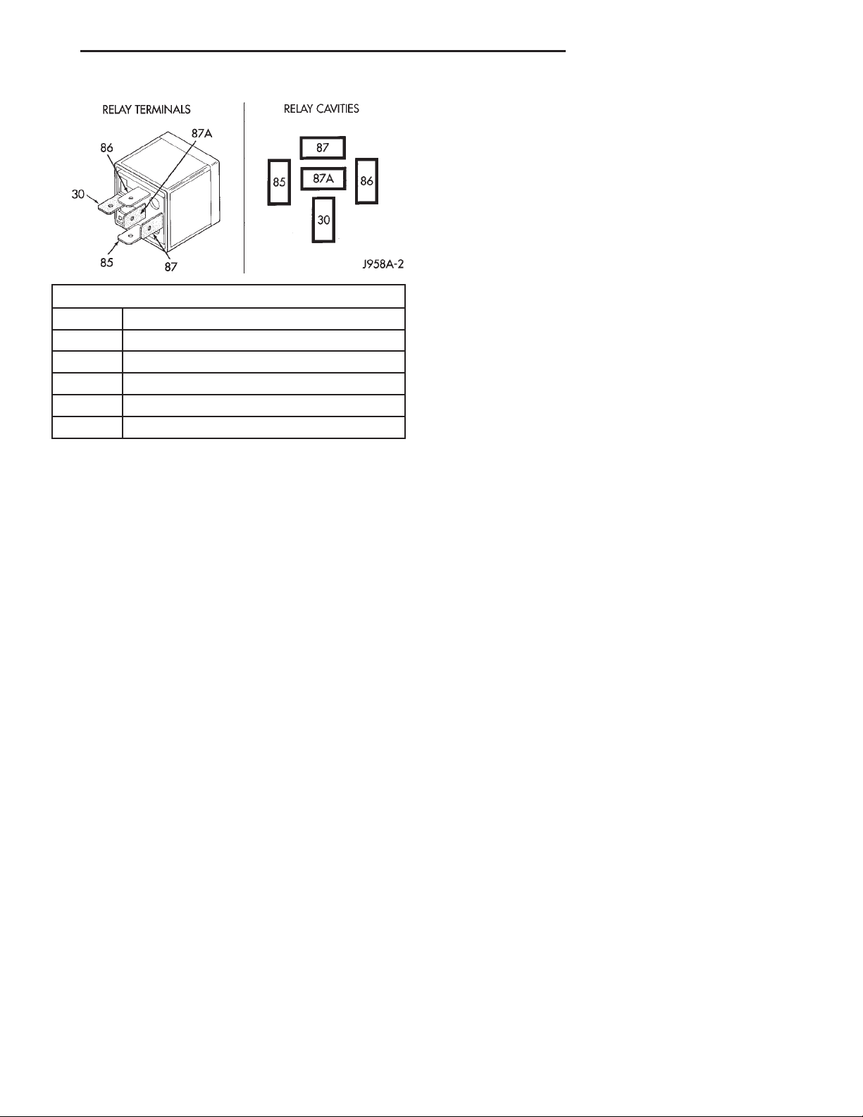
TERMINAL LEGEND
NUMBER IDENTIFICATION
30 COMMON FEED
85 COIL GROUND
86 COIL BATTERY
87 NORMALLY OPEN
87A NORMALLY CLOSED
Fig. 2 Starter Relay
The starter relay (Fig. 2) is an electromechanical
device that switches battery current to the pull-in
coil of the starter solenoid when the ignition switch
is turned to the Start position. The starter relay is
located in the Power Distribution Center (PDC), in
the engine compartment. See the fuse and relay layout label affixed to the inside surface of the PDC
cover for starter relay identification and location.
The starter relay is a International Standards
Organization (ISO) relay. Relays conforming to the
ISO specifications have common physical dimensions,
current capacities, terminal patterns, and terminal
functions.
The starter relay cannot be repaired or adjusted
and, if faulty or damaged, it must be replaced.
OPERATION
The ISO relay consists of an electromagnetic coil, a
resistor or diode, and three (two fixed and one movable)
electrical contacts. The movable (common feed) relay
contact is held against one of the fixed contacts (normally closed) by spring pressure. When the electromagnetic coil is energized, it draws the movable contact
away from the normally closed fixed contact, and holds
it against the other (normally open) fixed contact.
When the electromagnetic coil is de-energized,
spring pressure returns the movable contact to the
normally closed position. The resistor or diode is connected in parallel with the electromagnetic coil in the
relay, and helps to dissipate voltage spikes that are
produced when the coil is de-energized.
Page 4
8B - 4 STARTING SYSTEMS XJ
DIAGNOSIS AND TESTING
STARTING SYSTEM
DIAGNOSIS
The battery, starting system and charging system
in the vehicle operate with one another, and must be
tested as a complete system. In order for the engine
to start and the battery to charge properly, all of the
components that are used in these systems must perform within specifications. The service information
for these systems has been separated within this service manual to make it easier to locate the specific
information you are seeking. However, when
attempting to diagnose any of these systems, it is
important that you keep their interdependency in
mind.
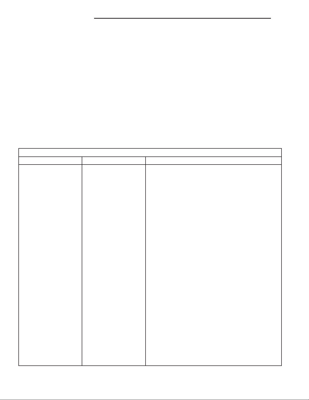
Starting System Diagnosis
Condition Possible Cause Correction
Starter fails to operate. 1. Battery discharged or
faulty.
2. Starting circuit wiring
faulty.
3. Starter relay faulty.
4. Ignition switch faulty.
5. Clutch pedal position
switch faulty.
6. Park/Neutral position
switch faulty or
misadjusted.
7. Starter solenoid faulty.
8. Starter motor faulty.
The diagnostic procedures used for the battery,
starting system and charging system include the
most basic conventional diagnostic methods, to the
more sophisticated On-Board Diagnostics (OBD) built
into the Powertrain Control Module (PCM). Use of an
induction-type milliampere ammeter, a volt/ohmmeter, a battery charger, a carbon pile rheostat (load
tester) and a 12-volt test lamp may be required. All
OBD-sensed systems are monitored by the PCM.
Each monitored circuit is assigned a Diagnostic Trouble Code (DTC). The PCM will store a DTC in electronic memory for any failure it detects. Refer to
Charging System, On-Board Diagnostic Test in
the index of this service manual for the location of
the proper on-board diagnostic test procedures.
1. Refer to Battery in the index of this service manual for
the location of the proper battery diagnosis and testing
procedures. Replace the faulty battery, as required.
2. Refer to Starting System in the index of this service
manual for the location of complete starting system wiring
diagrams. Test and repair the faulty starter feed and/or
control circuits, as required.
3. Refer to Starter Relay in the index of this service
manual for the location ofr the proper starter relay
diagnosis and testing procedures. Replace the faulty
starter relay, as required.
4. Refer to Ignition Switch and Key Lock Cylinder in the
index of this service manual for the location of the proper
ignition switch diagnosis and testing procedures. Replace
the faulty ignition switch, as required.
5. Refer to Clutch Pedal Position Switch in the index of
this service manual for the location of the proper clutch
pedal position switch diagnosis and testing procedures.
Replace the faulty clutch hydraulic linkage unit, as
required.
6. Refer to Park/Neutral Position Switch in the index of
this service manual for the location of the proper
park/neutral position switch diagnosis and testing
procedures. Replace the faulty park/neutral position
switch, as required.
7. Refer to Starter Motor in the index of this service
manual for the location of the proper starter solenoid
diagnosis and testing procedures. Replace the faulty
starter motor, as required.
8. Refer to Starter Motor in the index of this service
manual for the location of the proper starter motor
diagnosis and testing procedures. Replace the faulty
starter motor, as required.
Page 5

XJ STARTING SYSTEMS 8B - 5
DIAGNOSIS AND TESTING (Continued)
Starting System Diagnosis
Condition Possible Cause Correction
Starter engages, fails to
turn engine.
Starter engages, spins
out before engine starts.
Starter does not
disengage.
1. Battery discharged or
faulty.
2. Starting circuit wiring
faulty.
3. Starter motor faulty.
4. Engine seized.
1. Starter ring gear faulty.
2. Starter motor faulty.
1. Starter motor
improperly installed.
2. Starter relay faulty.
3. Ignition switch faulty.
4. Starter motor faulty.
1. Refer to Battery in the index of this service manual for
the location of the proper battery diagnosis and testing
procedures. Replace the faulty battery, as required.
2. Refer to Starting System in the index of this service
manual for the location of complete starting system wiring
diagrams. Test and repair the faulty starter feed and/or
control circuits, as required.
3. Refer to Starter Motor in the index of this service
manual for the location of the proper starter motor
diagnosis and testing procedures. Replace the faulty
starter motor, as required.
4. Refer to Engine Diagnosis in the index of this service
manual for the location of the proper engine diagnosis
and testing procedures. Repair or replace the faulty
engine, as required.
1. Refer to Starter Motor in the index of this service
manual for the location of the proper starter motor
removal and installation procedures. Remove the starter
motor to inspect the starter ring gear. Replace the faulty
starter ring gear, as required.
2. Refer to Starter Motor in the index of this service
manual for the location of the proper starter motor
diagnosis and testing procedures. Replace the faulty
starter motor, as required.
1. Refer to Starter Motor in the index of this service
manual for the location of the proper starter motor
installation procedures. Tighten the starter motor
mounting hardware to the correct tightness specifications,
as required.
2. Refer to Starter Relay in the index of this service
manual for the location of the proper starter relay
diagnosis and testing procedures. Replace the faulty
starter relay, as required.
3. Refer to Ignition Switch and Key Lock Cylinder in the
index of this service manual for the location of the proper
ignition switch diagnosis and testing procedures. Replace
the faulty ignition switch, as required.
4. Refer to Starter Motor in the index of this service
manual for the location of the proper starter motor
diagnosis and testing procedures. Replace the faulty
starter motor, as required.
TESTING
Before testing the starting system perform a visual
inspection of the starting system components and
connections. Refer to Starting System in the index
of this service manual for the location of the proper
starting system cleaning and inspection procedures.
COLD CRANKING TEST
Refer to Starting System in the index of this service manual for the location of complete starting sys-
tem wiring diagrams. Before performing this test, be
certain that the following procedures are accomplished:
• The battery is fully-charged and load tested.
Refer to Battery Charging in the index of this service manual for the location of the proper battery
charging procedures. Refer to Battery in the index of
this service manual for the location of the battery
diagnosis and testing procedures, including the
proper battery load test procedures.
Page 6
8B - 6 STARTING SYSTEMS XJ
DIAGNOSIS AND TESTING (Continued)
• Fully engage the parking brake.
• If the vehicle is equipped with an automatic
transmission, place the gearshift selector lever in the
Park position. If the vehicle is equipped with a manual transmission, place the gearshift selector lever in
the Neutral position and block the clutch pedal in the
fully depressed position.
• Verify that all lamps and accessories are turned
off.
• To prevent the engine from starting, remove the
Automatic ShutDown (ASD) relay. The ASD relay is
located in the Power Distribution Center (PDC), in
the engine compartment. See the fuse and relay layout label affixed to the underside of the PDC cover
for ASD relay identification and location.
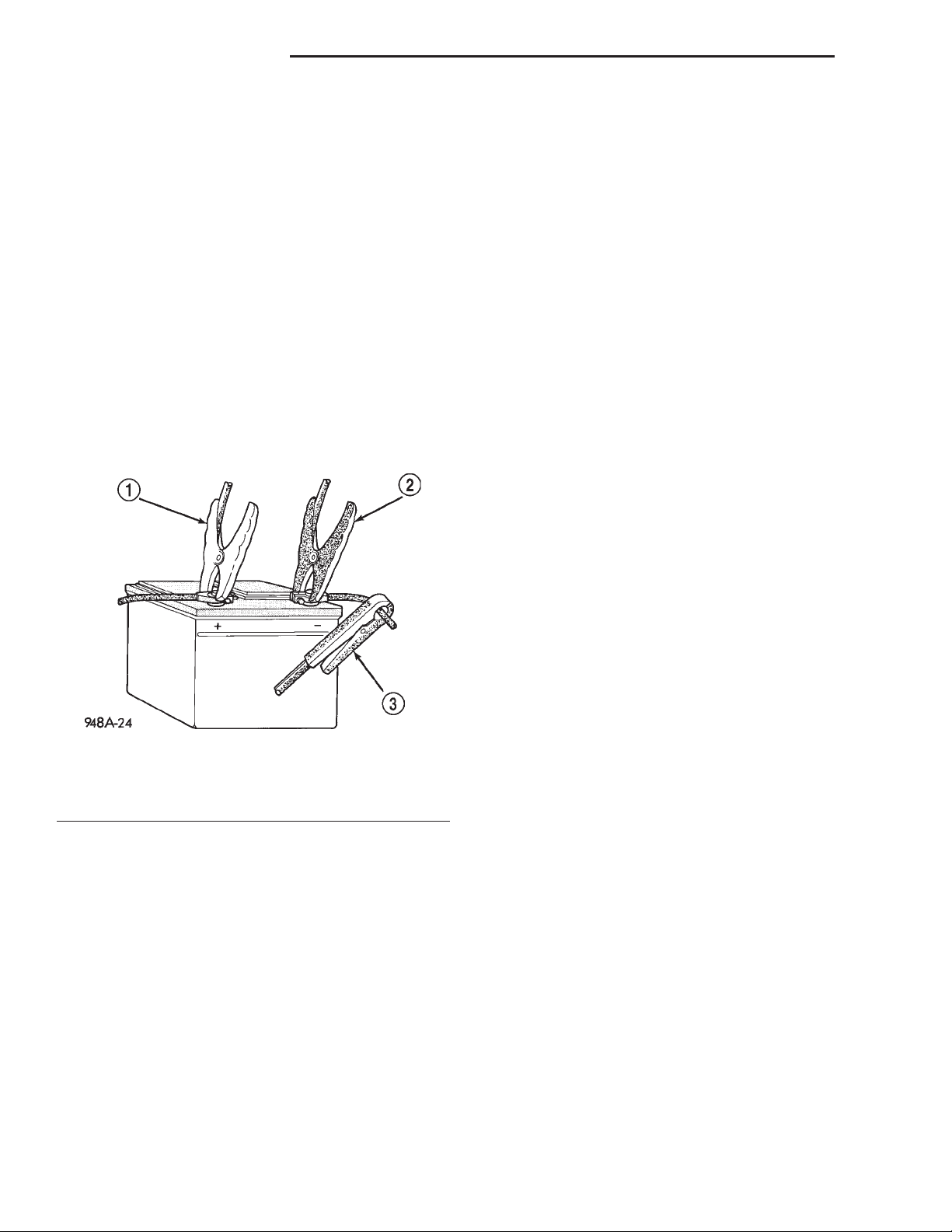
(1) Connect a suitable volt-ampere tester to the
battery terminals (Fig. 3). See the instructions provided by the manufacturer of the volt-ampere tester
being used.
Fig. 3 Volts-Amps Tester Connections - Typical
1 – POSITIVE CLAMP
2 – NEGATIVE CLAMP
3 – INDUCTION AMMETER CLAMP
(2) Rotate and hold the ignition switch in the Start
position. Note the cranking voltage and current
(amperage) draw readings shown on the volt-ampere
tester.
(a) If the voltage reads below 9.6 volts, refer to
Starter Motor in the index of this service manual
for the location of the proper starter motor diagnosis and testing procedures. If the starter motor
tests OK, refer to Engine Diagnosis in the index
of this service manual for the location of the proper
engine diagnosis and testing procedures. If the
starter motor is not OK, replace the faulty starter
motor.
(b) If the voltage reads above 9.6 volts and the
current (amperage) draw reads below specifications, refer to the Feed Circuit Test in this sec-
tion.
(c) If the voltage reads 12.5 volts or greater and
the starter motor does not turn, refer to the Con-
trol Circuit Test in this section.
(d) If the voltage reads 12.5 volts or greater and
the starter motor turns very slowly, refer to the
Feed Circuit Test in this section.
NOTE: A cold engine will increase the starter current (amperage) draw reading, and reduce the battery voltage reading.
FEED CIRCUIT TEST
The starter feed circuit test (voltage drop method)
will determine if there is excessive resistance in the
high-amperage starter feed circuit. Refer to Starting
System in the index of this service manual for the
location of complete starting system wiring diagrams.
When performing the voltage drop test, it is impor-
tant to remember that the voltage drop is giving an
indication of the resistance between the two points at
which the voltmeter probes are attached. EXAM-
PLE: When testing the resistance of the battery positive cable, touch the voltmeter leads to the battery
positive cable terminal clamp and to the battery positive cable eyelet terminal at the starter solenoid
B(+) terminal stud. If you probe the battery positive
terminal post and the battery positive cable eyelet
terminal at the starter solenoid B(+) terminal stud,
you are reading the combined voltage drop in the
battery positive cable terminal clamp-to-terminal
post connection and the battery positive cable.
The following operation will require a voltmeter
accurate to 1/10 (0.10) volt. Before performing this
test, be certain that the following procedures are
accomplished:
• The battery is fully-charged and load tested.
Refer to Battery Charging in the index of this service manual for the location of the proper battery
charging procedures. Refer to Battery in the index of
this service manual for the location of the battery
diagnosis and testing procedures, including the
proper battery load test procedures.
• Fully engage the parking brake.
• If the vehicle is equipped with an automatic
transmission, place the gearshift selector lever in the
Park position. If the vehicle is equipped with a manual transmission, place the gearshift selector lever in
the Neutral position and block the clutch pedal in the
fully depressed position.
• Verify that all lamps and accessories are turned
off.
Page 7
XJ STARTING SYSTEMS 8B - 7
DIAGNOSIS AND TESTING (Continued)
• To prevent the engine from starting, remove the
Automatic ShutDown (ASD) relay. The ASD relay is
located in the Power Distribution Center (PDC), in
the engine compartment. See the fuse and relay layout label affixed to the underside of the PDC cover
for ASD relay identification and location.
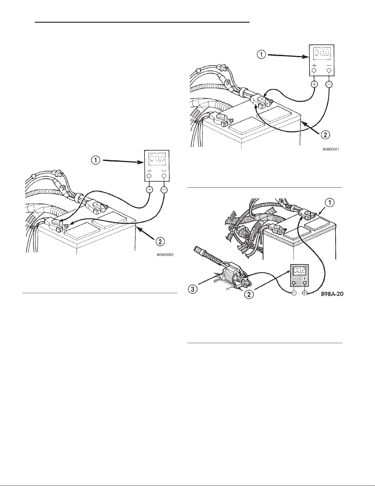
(1) Connect the positive lead of the voltmeter to
the battery negative terminal post. Connect the negative lead of the voltmeter to the battery negative
cable terminal clamp (Fig. 4). Rotate and hold the
ignition switch in the Start position. Observe the
voltmeter. If voltage is detected, correct the poor contact between the battery negative cable terminal
clamp and the battery negative terminal post.
Fig. 5 Test Battery Positive Connection Resistance -
Typical
1 – VOLTMETER
2 – BATTERY
Fig. 4 Test Battery Negative Connection Resistance
- Typical
1 – VOLTMETER
2 – BATTERY
(2) Connect the positive lead of the voltmeter to
the battery positive terminal post. Connect the negative lead of the voltmeter to the battery positive cable
terminal clamp (Fig. 5). Rotate and hold the ignition
switch in the Start position. Observe the voltmeter. If
voltage is detected, correct the poor connection
between the battery positive cable terminal clamp
and the battery positive terminal post.
(3) Connect the voltmeter to measure between the
battery positive cable terminal clamp and the starter
solenoid B(+) terminal stud (Fig. 6). Rotate and hold
the ignition switch in the Start position. Observe the
voltmeter. If the reading is above 0.2 volt, clean and
tighten the battery positive cable eyelet terminal connection at the starter solenoid B(+) terminal stud.
Repeat the test. If the reading is still above 0.2 volt,
replace the faulty battery positive cable.
Fig. 6 Test Battery Positive Cable Resistance -
Typical
1 – BATTERY
2 – VOLTMETER
3 – STARTER MOTOR
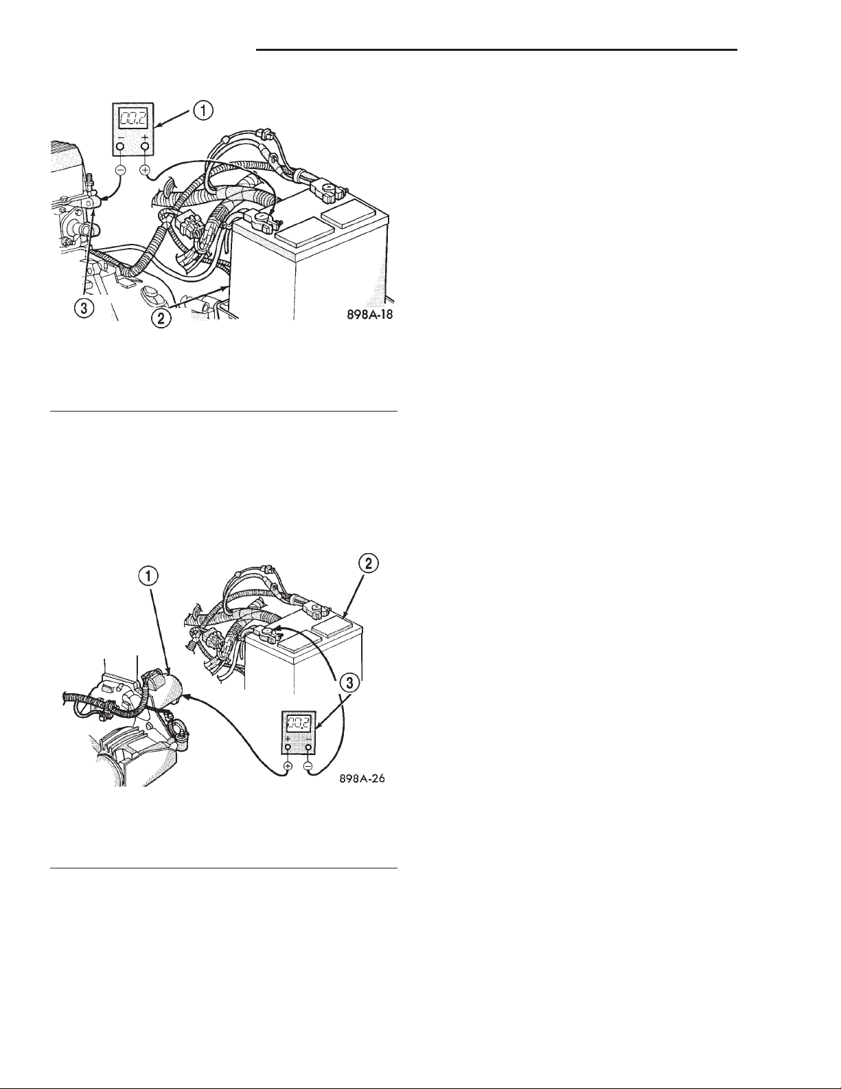
(4) Connect the voltmeter to measure between the
battery negative cable terminal clamp and a good
clean ground on the engine block (Fig. 7). Rotate and
hold the ignition switch in the Start position.
Observe the voltmeter. If the reading is above 0.2
volt, clean and tighten the battery negative cable
eyelet terminal connection to the engine block.
Repeat the test. If the reading is still above 0.2 volt,
replace the faulty battery negative cable.
Page 8
8B - 8 STARTING SYSTEMS XJ
DIAGNOSIS AND TESTING (Continued)
If the resistance tests detect no feed circuit problems, refer to Starter Motor in the index of this service manual for the location of the proper starter
motor diagnosis and testing procedures.
CONTROL CIRCUIT TEST
The starter control circuit components should be
tested in the order in which they are listed, as follows:
• Starter Relay Refer to Starter Relay in the
index of this service manual for the location of the
proper starter relay diagnosis and testing procedures.
• Starter Solenoid Refer to Starter Motor in the
index of this service manual for the location of the
proper starter solenoid diagnosis and testing proce-
Fig. 7 Test Ground Circuit Resistance - Typical
1 – VOLTMETER
2 – BATTERY
3 – ENGINE GROUND
(5) Connect the positive lead of the voltmeter to
the starter housing. Connect the negative lead of the
voltmeter to the battery negative terminal post (Fig.
8). Rotate and hold the ignition switch in the Start
position. Observe the voltmeter. If the reading is
above 0.2 volt, correct the poor starter to engine
block ground contact.
dures.
• Ignition Switch Refer to Ignition Switch and
Key Lock Cylinder in the index of this service
manual for the location of the proper ignition switch
diagnosis and testing procedures.
• Clutch Pedal Position Switch If the vehicle is
equipped with a manual transmission, refer to
Clutch Pedal Position Switch in the index of this
service manual for the location of the proper clutch
pedal position switch diagnosis and testing procedures.
• Park/Neutral Position Switch If the vehicle is
equipped with an automatic transmission, refer to
Park/Neutral Position Switch in the index of this
service manual for the location of the proper park/
neutral position switch diagnosis and testing procedures.
Fig. 8 Test Starter Ground - Typical
1 – STARTER MOTOR
2 – BATTERY
3 – VOLTMETER
STARTER MOTOR NOISE - 2.5L ENGINE
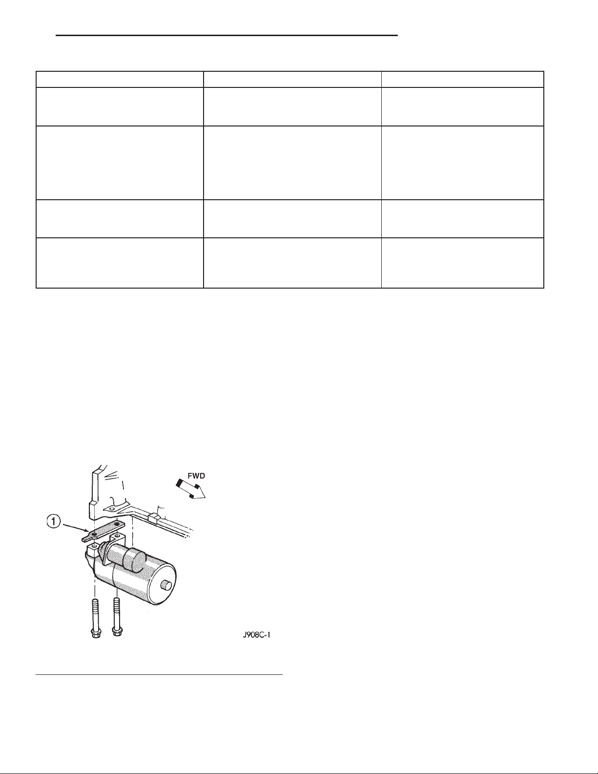
See the Starter Motor Noise Diagnosis chart (Fig.
9). If the complaint is similar to Conditions 1 and 2
in the chart, correction can be made by placing shims
between the starter motor and the engine block using
the following procedures:
Page 9
XJ STARTING SYSTEMS 8B - 9
DIAGNOSIS AND TESTING (Continued)
CONDITION POSSIBLE CAUSE CORRECTION
1. VERY HIGH FREQUENCY
WHINE BEFORE ENGINE
STARTS; ENGINE STARTS OK.
2. VERY HIGH FREQUENCY
WHINE AFTER ENGINE STARTS
WITH IGNITION KEY RELEASED.
ENGINE STARTS OK.
3. A LOUD “WHOOP” AFTER
ENGINE STARTS WHILE
STARTER MOTOR IS ENGAGED.
4. A “RUMBLE,” “GROWL,” OR
“KNOCK” AS STARTER MOTOR
COASTS TO STOP AFTER
ENGINE STARTS.
NOTE: A high frequency whine during cranking is normal for this starter motor.
FIG. 9 STARTER MOTOR NOISE DIAGNOSIS
1. Excessive distance between pinion
gear and flywheel/drive plate gear.
2. Insufficient distance between
starter motor pinion gear and
flywheel/drive plate runout can cause
noise to be intermittent.
3. Most probably cause is defective
overrunning clutch.
4. Most probable cause is bent or
unbalanced starter motor armature.
1. Move starter motor toward
flywheel/drive plate by removing
shim(s), if possible.
2. Shim starter motor away from
flywheel/drive plate. Inspect
flywheel/drive plate for damage;
bent, unusual wear, and excessive
runout. Replace flywheel/drive
plate as necessary.
3. Replace starter motor.
4. Replace starter motor.
(1) If the complaint is similar to Condition 1, the
starter motor must be moved toward the starter ring
gear by removing shims from both starter mounting
pads on the engine block (Fig. 10). Refer to Starter
Motor in the index of this service manual for the
location of the proper starter motor removal and
installation procedures.
NOTE: The shim thickness is 0.381 mm (0.015 in.).
These shims may be stacked if additional thickness
is required.
Fig. 10 Starter Motor Shim
1 – STARTER MOTOR SHIM
(2) If the complaint is similar to Condition 2, the
starter motor must be moved away from the starter
ring gear. This is done by installing shim(s) across
both starter mounting pads on the engine block.
More than one shim may be required. Refer to
Starter Motor in the index of this service manual
for the location of the proper removal and installation procedures.
NOTE: This is a condition that will generally cause
broken starter (flywheel/torque converter drive
plate) ring gear teeth or broken starter motor housings.
STARTER MOTOR
Correct starter motor operation can be confirmed
by performing the following free running bench test.
This test can only be performed with the starter
motor removed from the vehicle. Refer to Starting
System in the index of this service manual for the
location of the proper starter motor specifications.
CAUTION: The 2.5L engine uses a permanent magnet starter. Permanent magnet starters are highly
sensitive to hammering, shocks, external pressure
and reverse polarity. This starter motor must never
be clamped in a vise by the starter field frame. The
starter should only be clamped by the mounting
flange. Do not reverse the battery cable connections to this starter motor when testing. The permanent magnets may be damaged and the starter
rendered unserviceable if it is subjected to any of
these conditions.
Page 10
8B - 10 STARTING SYSTEMS XJ
DIAGNOSIS AND TESTING (Continued)
STARTER MOTOR
(1) Remove the starter motor from the vehicle.
Refer to Starter Motor in the index of this service
manual for the location of the proper starter motor
removal and installation procedures.
(2) Mount the starter motor securely in a softjawed bench vise. The vise jaws should be clamped
on the mounting flange of the starter motor. Never
clamp on the starter motor by the field frame.
(3) Connect a suitable volt-ampere tester and a
12-volt battery to the starter motor in series, and set
the ammeter to the 100 ampere scale. See the
instructions provided by the manufacturer of the
volt-ampere tester being used.
(4) Install a jumper wire from the solenoid terminal to the solenoid B(+) terminal stud. The starter
motor should operate. If the starter motor fails to
operate, replace the faulty starter motor.
(5) Adjust the carbon pile load of the tester to
obtain the free running test voltage. Refer to Start-
ing System in the index of this service manual for
the location of the proper starter motor free running
test voltage specifications.
(6) Note the reading on the ammeter and compare
this reading to the free running test maximum
amperage draw. Refer to Starting System in the
index of this service manual for the location of the
proper starter motor free running test maximum
amperage draw specifications.
(7) If the ammeter reading exceeds the maximum
amperage draw specification, replace the faulty
starter motor.
STARTER SOLENOID
This test can only be performed with the starter
motor removed from the vehicle.
(1) Remove the starter motor from the vehicle.
Refer to Starter Motor in the index of this service
manual for the location of the proper starter motor
removal and installation procedures.
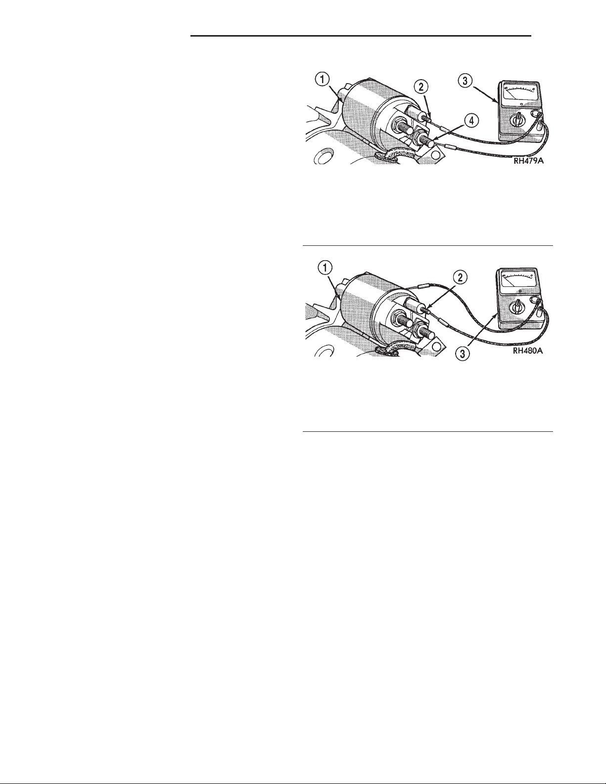
(2) Disconnect the wire from the solenoid field coil
terminal.
(3) Check for continuity between the solenoid terminal and the solenoid field coil terminal with a continuity tester (Fig. 11). There should be continuity. If
OK, go to Step 4. If not OK, replace the faulty starter
motor.
(4) Check for continuity between the solenoid terminal and the solenoid case (Fig. 12). There should
be continuity. If not OK, replace the faulty starter
motor.
STARTER RELAY
The starter relay (Fig. 13) is located in the Power
Distribution Center (PDC), in the engine compartment. Refer to the fuse and relay layout label affixed
Fig. 11 Continuity Test Between Solenoid Terminal
and Field Coil Terminal - Typical
1 – SOLENOID
2 – SOLENOID TERMINAL
3 – OHMMETER
4 – FIELD COIL TERMINAL
Fig. 12 Continuity Test Between Solenoid Terminal
and Solenoid Case - Typical
1 – SOLENOID
2 – SOLENOID TERMINAL
3 – OHMMETER
to the underside of the PDC cover for starter relay
identification and location. Refer to Starting Sys-
tem in the index of this service manual for the location of complete starting system wiring diagrams.
RELAY TEST
(1) Remove the starter relay from the PDC. Refer
to Starter Relay in the index of this service manual
for the location of the proper starter relay removal
and installation procedures.
(2) A relay in the de-energized position should
have continuity between terminals 87A and 30, and
no continuity between terminals 87 and 30. If OK, go
to Step 3. If not OK, replace the faulty relay.
(3) Resistance between terminals 85 and 86 (electromagnet) should be 75 6 5 ohms. If OK, go to Step
4. If not OK, replace the faulty relay.
(4) Connect a battery to terminals 85 and 86.
There should now be continuity between terminals
30 and 87, and no continuity between terminals 87A
and 30. If OK, perform the Relay Circuit Test that
follows. If not OK, replace the faulty relay.
Page 11
XJ STARTING SYSTEMS 8B - 11
DIAGNOSIS AND TESTING (Continued)
mission or if not OK with an automatic transmission,
check for an open or shorted fused ignition switch
output (start) circuit to the ignition switch and
repair, as required. If the fused ignition switch output (start) circuit is OK, refer to Ignition Switch
and Key Lock Cylinder in the index of this service
manual for the location of the proper ignition switch
diagnosis and testing procedures.
(5) The coil ground terminal (85) is connected to
the electromagnet in the relay. On vehicles with a
manual transmission, it is grounded at all times. On
TERMINAL LEGEND
NUMBER IDENTIFICATION
30 COMMON FEED
85 COIL GROUND
86 COIL BATTERY
87 NORMALLY OPEN
87A NORMALLY CLOSED
Fig. 13 Starter Relay
RELAY CIRCUIT TEST
(1) The relay common feed terminal cavity (30) is
connected to battery voltage and should be hot at all
times. If OK, go to Step 2. If not OK, repair the open
circuit to the fused B(+) fuse in the PDC as required.
(2) The relay normally closed terminal (87A) is
connected to terminal 30 in the de-energized position,
but is not used for this application. Go to Step 3.
(3) The relay normally open terminal (87) is connected to the common feed terminal (30) in the energized position. This terminal supplies battery voltage
to the starter solenoid field coil. There should be continuity between the cavity for relay terminal 87 and
the starter solenoid terminal at all times. If OK, go
to Step 4. If not OK, repair the open engine starter
motor relay output circuit to the starter solenoid as
required.
(4) The coil battery terminal (86) is connected to
the electromagnet in the relay. It is energized when
the ignition switch is held in the Start position. On
vehicles with a manual transmission, the clutch
pedal must be blocked in the fully depressed position
for this test. Check for battery voltage at the cavity
for relay terminal 86 with the ignition switch in the
Start position, and no voltage when the ignition
switch is released to the On position. If OK, go to
Step 5. If not OK with a manual transmission, disconnect the clutch pedal position switch wire harness
connector and install a jumper wire between the two
cavities in the body half of the connector and check
for battery voltage again at the cavity for relay terminal 86. If now OK, replace the faulty clutch pedal
position switch. If still not OK with a manual trans-
vehicles with an automatic transmission, it is
grounded through the park/neutral position switch
only when the gearshift selector lever is in the Park
or Neutral positions. Check for continuity to ground
at the cavity for relay terminal 85. If not OK with a
manual transmission, repair the open park/neutral
position switch sense circuit to ground as required. If
not OK with an automatic transmission, check for an
open or shorted park/neutral position switch sense
circuit to the park/neutral position switch and repair,
as required. If the park/neutral position switch sense
circuit checks OK, refer to Park/Neutral Position
Switch in the index of this service manual for the
location of the proper park/neutral position switch
diagnosis and testing procedures.
REMOVAL AND INSTALLATION
STARTER MOTOR
REMOVAL
2.5L ENGINE
(1) Disconnect and isolate the battery negative
cable.
(2) Raise and support the vehicle.
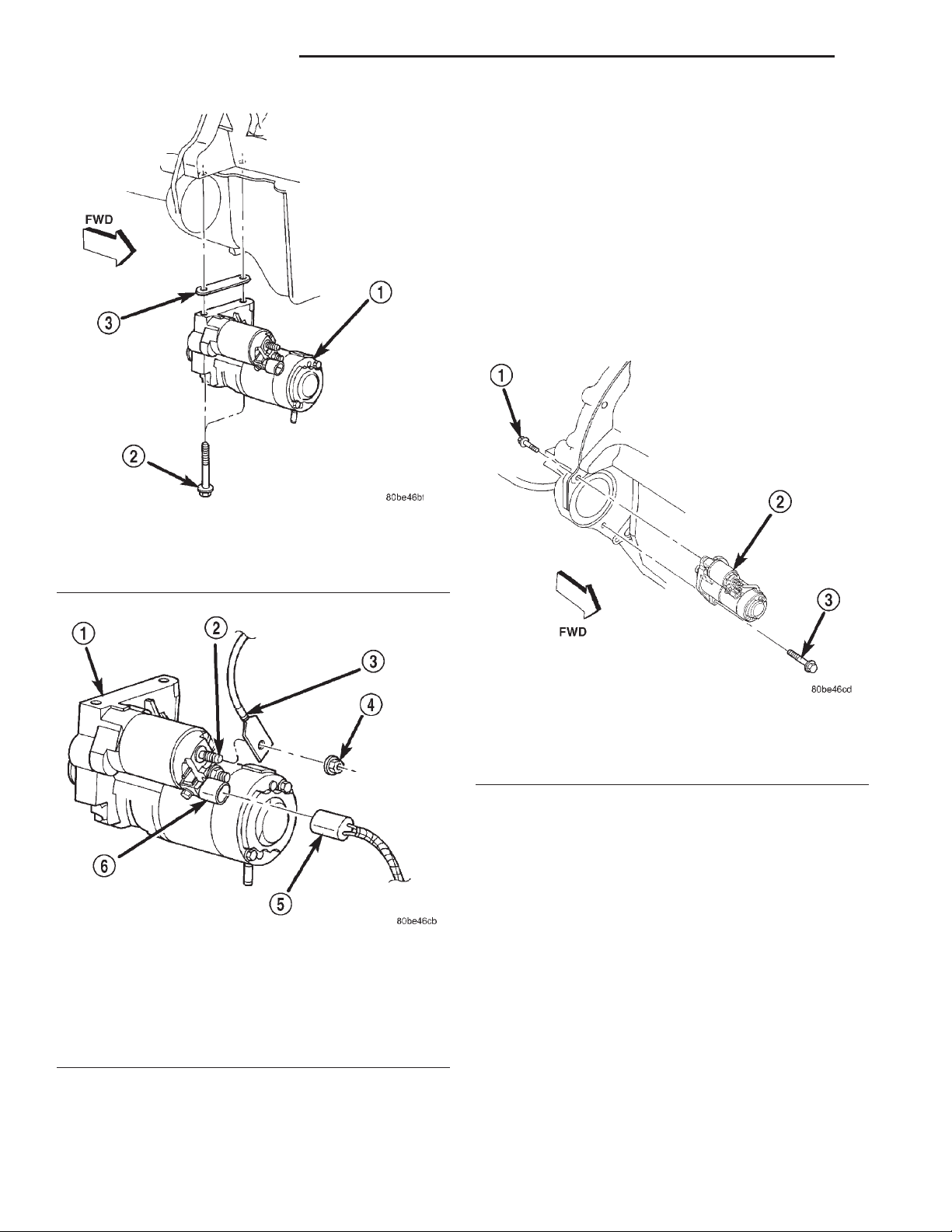
(3) While supporting the starter motor with one
hand, use the other hand to remove the two screws
that secure the starter motor to the engine block
(Fig. 14).
(4) Lower the starter motor from the engine block
far enough to access and remove the nut that secures
the battery positive cable eyelet terminal to the
starter solenoid B(+) terminal stud (Fig. 15). Always
support the starter motor during this process. Do not
let the starter motor hang from the wire harness.
(5) Remove the battery positive cable eyelet terminal from the starter solenoid B(+) terminal stud.
Always support the starter motor during this process.
Do not let the starter motor hang from the wire harness.
Page 12
8B - 12 STARTING SYSTEMS XJ
REMOVAL AND INSTALLATION (Continued)
during this process. Do not let the starter motor
hang from the wire harness.
(7) Remove the starter motor and any starter
motor shims (if used) from the engine block.
4.0L ENGINE
(1) Disconnect and isolate the battery negative
cable.
(2) Raise and support the vehicle.
(3) Remove the lower screw (forward facing) that
secures the starter motor to the manual transmission
clutch housing or the automatic transmission torque
converter housing (Fig. 16).
Fig. 14 Starter Motor Remove/Install - 2.5L Engine
1 – STARTER MOTOR
2 – SCREW (2)
3 – SHIM
Fig. 15 Starter Connections Remove/Install - Typical
1 – STARTER MOTOR
2 – SOLENOID B(+) TERMINAL STUD
3 – BATTERY POSITIVE CABLE EYELET TERMINAL
4 – NUT
5 – SOLENOID TERMINAL WIRE HARNESS CONNECTOR
6 – SOLENOID TERMINAL CONNECTOR RECEPTACLE
(6) Disconnect the solenoid terminal wire harness
connector from the connector receptacle on the
starter solenoid. Always support the starter motor
Fig. 16 Starter Motor Remove/Install - 4.0L Engine
1 – SCREW
2 – STARTER MOTOR
3 – SCREW
(4) While supporting the starter motor with one
hand, use the other hand to remove the upper screw
(rearward facing) that secures the starter motor to
the manual transmission clutch housing or the automatic transmission torque converter housing.
(5) Lower the starter motor from the front of the
manual transmission clutch housing or automatic
transmission torque converter housing far enough to
access and remove the nut that secures the battery
positive cable eyelet terminal to the starter solenoid
B(+) terminal stud (Fig. 15). Always support the
starter motor during this process. Do not let the
starter motor hang from the wire harness.
(6) Remove the battery positive cable eyelet terminal from the solenoid B(+) terminal stud. Always
support the starter motor during this process. Do not
let the starter motor hang from the wire harness.
(7) Disconnect the solenoid terminal wire harness
connector from the connector receptacle on the
Page 13

XJ STARTING SYSTEMS 8B - 13
REMOVAL AND INSTALLATION (Continued)
starter solenoid. Always support the starter motor
during this process. Do not let the starter motor
hang from the wire harness.
(8) Remove the starter motor from the manual
transmission clutch housing or automatic transmission torque converter housing.
INSTALLATION
2.5L ENGINE
(1) Position the starter motor to the engine block.
(2) Reconnect the solenoid terminal wire harness
connector to the connector receptacle on the starter
solenoid. Always support the starter motor during
this process. Do not let the starter motor hang from
the wire harness.
(3) Install the battery positive cable eyelet terminal onto the starter solenoid B(+) terminal stud.
Always support the starter motor during this process.
Do not let the starter motor hang from the wire harness.
(4) Install and tighten the nut that secures the
battery positive cable eyelet terminal to the starter
solenoid B(+) terminal stud. Tighten the nut to 11.3
N·m (100 in. lbs.). Always support the starter motor
during this process. Do not let the starter motor
hang from the wire harness.
(5) Position the starter motor and any starter
motor shims that were removed during the starter
motor removal procedure to the engine block. Loosely
install the two starter motor mounting screws to
secure the starter motor and shims to the engine
block.
NOTE: Shim thickness available is 0.381 mm (0.015
in.). Refer to Starter Motor Noise - 2.5L Engine in
the index of this service manual for the location of
the proper starter motor noise diagnosis and testing procedures.
Always support the starter motor during this process.
Do not let the starter motor hang from the wire harness.
(4) Install and tighten the nut that secures the
battery positive cable eyelet terminal to the starter
solenoid B(+) terminal stud. Tighten the nut to 11.3
N·m (100 in. lbs.). Always support the starter motor
during this process. Do not let the starter motor
hang from the wire harness.
(5) Position the starter motor to the manual transmission clutch housing or automatic transmission
torque converter housing. Loosely install the two
starter motor mounting screws to secure the starter
motor to the manual transmission clutch housing or
automatic transmission torque converter housing.
(6) Tighten the lower (forward facing) screw that
secures the starter motor to the manual transmission
clutch housing or automatic transmission torque converter housing. Tighten the screw to 40.7 N·m (30 ft.
lbs.).
(7) Tighten the upper (rearward facing) screw that
secures the starter motor to the manual transmission
clutch housing or automatic transmission torque converter housing. Tighten the screw to 47.5 N·m (35 ft.
lbs.).
(8) Lower the vehicle.
(9) Reconnect the battery negative cable.
STARTER RELAY
REMOVAL
(1) Disconnect and isolate the battery negative
cable.
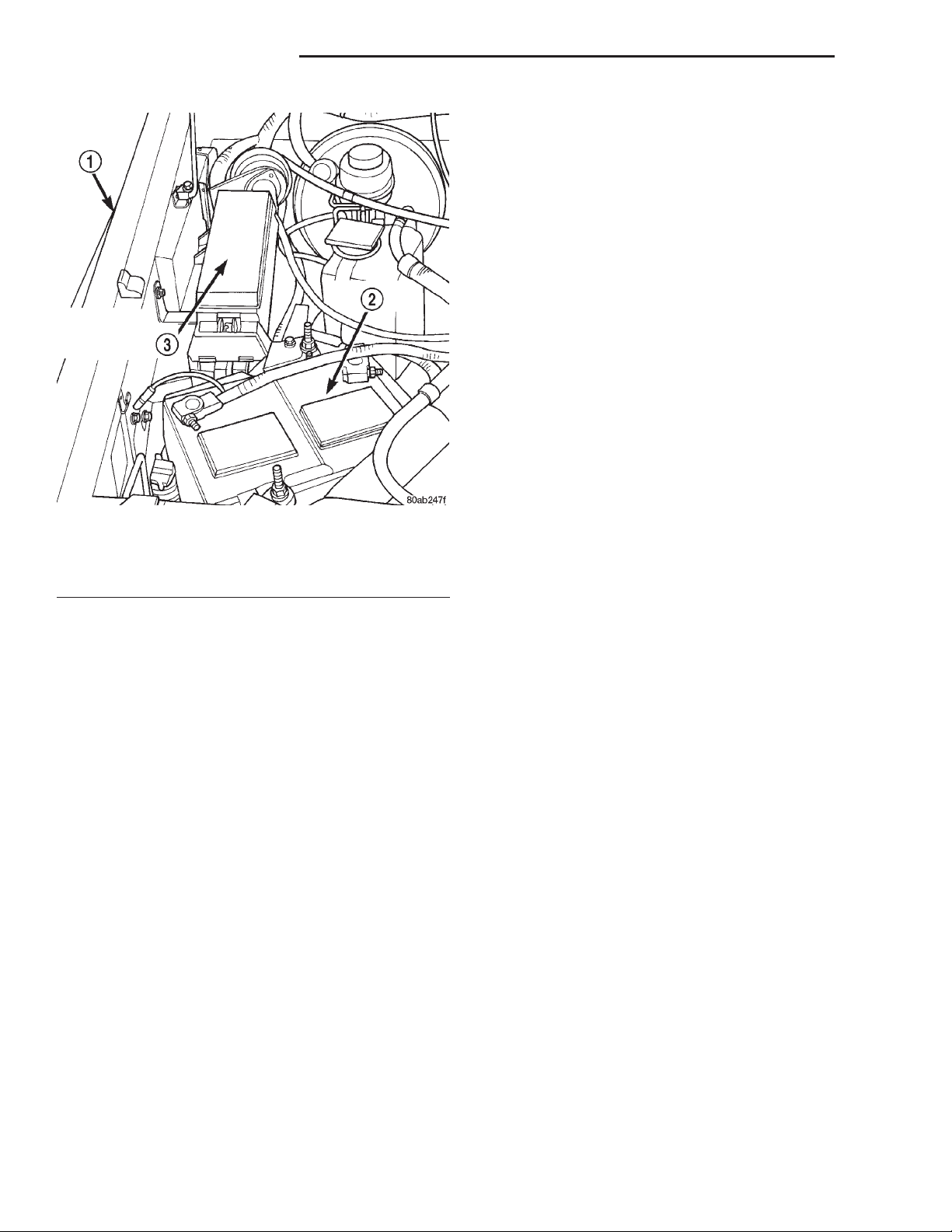
(2) Remove the cover from the Power Distribution
Center (PDC) (Fig. 17).
(3) See the fuse and relay layout label affixed to
the underside of the PDC cover for starter relay identification and location.
(4) Remove the starter relay from the PDC.
(6) Tighten the two screws that secure the starter
motor and shims to the engine block. Tighten the
screws to 44.7 N·m (33 ft. lbs.).
(7) Lower the vehicle.
(8) Reconnect the battery negative cable.
4.0L ENGINE
(1) Position the starter motor to the manual transmission clutch housing or automatic transmission
torque converter housing.
(2) Reconnect the solenoid terminal wire harness
connector to the connector receptacle on the starter
solenoid. Always support the starter motor during
this process. Do not let the starter motor hang from
the wire harness.
(3) Install the battery positive cable eyelet terminal onto the starter solenoid B(+) terminal stud.
INSTALLATION
(1) See the fuse and relay layout label affixed to
the underside of the PDC cover for the proper starter
relay location.
(2) Position the starter relay in the proper receptacle in the PDC.
(3) Align the starter relay terminals with the terminal cavities in the PDC receptacle.
(4) Push down firmly on the starter relay until the
terminals are fully seated in the terminal cavities in
the PDC receptacle.
(5) Install the cover onto the PDC.
(6) Reconnect the battery negative cable.
Page 14
8B - 14 STARTING SYSTEMS XJ
REMOVAL AND INSTALLATION (Continued)
• Ignition Switch Visually inspect the ignition
switch for indications of physical damage and loose
or corroded wire harness connections. Clean corroded
connections as required. Refer to Wiring Diagrams
in the index of this service manual for the location of
the proper wiring repair or connector and terminal
service procedures. Refer to Ignition Switch and
Key Lock Cylinder in the index of this service
manual for the location of the proper ignition switch
service procedures.
• Clutch Pedal Position Switch If the vehicle is
equipped with a manual transmission, visually
inspect the clutch pedal position switch for indications of physical damage and loose or corroded wire
harness connections. Clean corroded connections as
required. Refer to Wiring Diagrams in the index of
this service manual for the location of the proper wiring repair or connector and terminal service procedures. Refer to Clutch Hydraulic Linkage in the
index of this service manual for the location of the
proper clutch pedal position switch service procedures.
Fig. 17 Power Distribution Center
1 – RIGHT FENDER
2 – BATTERY
3 – POWER DISTRIBUTION CENTER
CLEANING AND INSPECTION
STARTING SYSTEM
The following components of the starting system
should be carefully inspected whenever any starting
system problem is encountered.
WARNING: ON VEHICLES EQUIPPED WITH AIRBAGS, DISABLE THE AIRBAG SYSTEM BEFORE
ATTEMPTING ANY STEERING WHEEL, STEERING
COLUMN, OR INSTRUMENT PANEL COMPONENT
DIAGNOSIS OR SERVICE. DISCONNECT AND ISOLATE THE BATTERY NEGATIVE (GROUND) CABLE,
THEN WAIT TWO MINUTES FOR THE AIRBAG SYSTEM CAPACITOR TO DISCHARGE BEFORE PERFORMING FURTHER DIAGNOSIS OR SERVICE. THIS
IS THE ONLY SURE WAY TO DISABLE THE AIRBAG
SYSTEM. FAILURE TO TAKE THE PROPER PRECAUTIONS COULD RESULT IN ACCIDENTAL AIRBAG DEPLOYMENT AND POSSIBLE PERSONAL
INJURY.
• Battery Visually inspect the battery for indications of physical damage and loose or corroded cable
connections. Determine the state-of-charge and
cranking capacity of the battery. Charge or replace
the battery, if required. Refer to Battery in the index
of this service manual for the location of the proper
battery cleaning and inspection procedures.
• Park/Neutral Position Switch If the vehicle is
equipped with an automatic transmission, visually
inspect the park/neutral position switch for indications of physical damage and loose or corroded wire
harness connections. Clean corroded connections as
required. Refer to Wiring Diagrams in the index of
this service manual for the location of the proper wiring repair or connector and terminal service procedures. Refer to Park/Neutral Position Switch in
the index of this service manual for the location of
the proper park/neutral position switch service procedures.
• Starter Relay Visually inspect the starter relay
for indications of physical damage and loose or corroded wire harness connections. Clean corroded connections as required. Refer to Wiring Diagrams in
the index of this service manual for the location of
the proper wiring repair or connector and terminal
service procedures. Refer to Starter Relay in the
index of this service manual for the location of the
proper starter relay service procedures.
• Starter Motor Visually inspect the starter motor
for indications of physical damage and loose or corroded wire harness connections. Clean corroded connections as required. Refer to Wiring Diagrams in
the index of this service manual for the location of
the proper wiring repair or connector and terminal
service procedures. If the problem being diagnosed
involves improper starter engagement, disengagement or noise complaints the starter motor should be
removed. With the starter motor removed, inspect
the starter pinion and ring gears for damaged or
missing teeth. Replace faulty components as
required. Refer to Starter Motor in the index of this
Page 15
XJ STARTING SYSTEMS 8B - 15
CLEANING AND INSPECTION (Continued)
service manual for the location of the proper starter
motor removal and installation procedures.
• Starter Solenoid Visually inspect the starter
solenoid for indications of physical damage and loose
or corroded wire harness connections. Clean corroded
connections as required. Refer to Wiring Diagrams
in the index of this service manual for the location of
the proper wiring repair or connector and terminal
service procedures. Refer to Starter Motor in the
index of this service manual for the location of the
proper starter solenoid service procedures.
• Wiring Visually inspect the starting system wire
harnesses for indications of physical damage. Repair
or replace any faulty wiring, as required. Refer to
Starting System in the index of this service manual
for the location of complete starting system wiring
diagrams. Refer to Wiring Diagrams in the index of
this service manual for the location of the proper wiring repair or connector and terminal service procedures.
SPECIFICATIONS
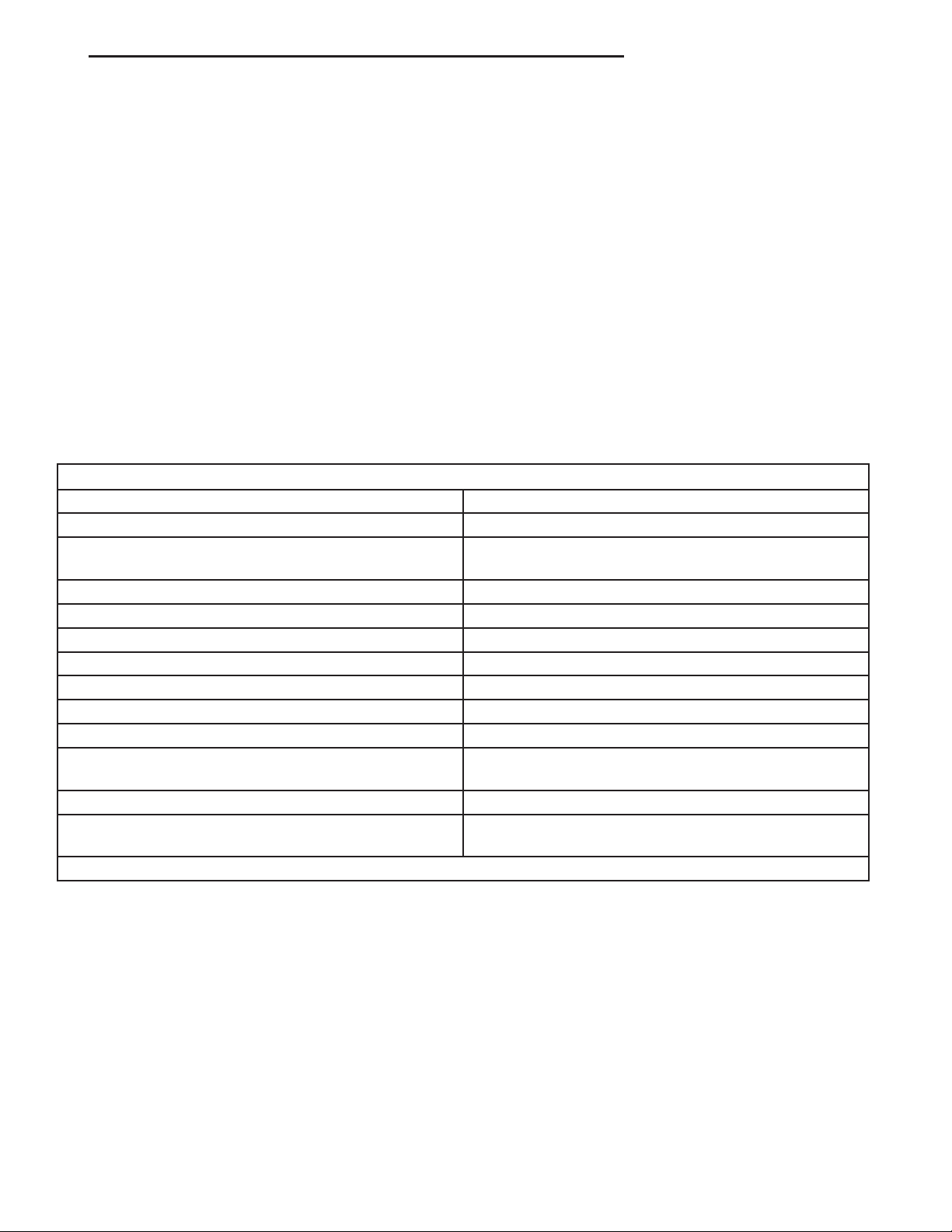
STARTING SYSTEM
Starter Motor and Solenoid
Manufacturer Mitsubishi
Engine Application 2.5L, 4.0L
Power Rating
Voltage 12 Volts
Number of Fields 4
Number of Poles 4
Number of Brushes 4
Drive Type Planetary Gear Reduction
Free Running Test Voltage 11.2 Volts
Free Running Test Maximum Amperage Draw 90 Amperes
Free Running Test Minimum Speed
Solenoid Closing Maximum Voltage Required 7.8 Volts
*Cranking Amperage Draw Test
*Test at operating temperature. Cold engine, tight (new) engine, or heavy oil will increase starter amperage draw.
2.5L - 1.2 Kilowatt (1.6 Horsepower)
4.0L - 1.4 Kilowatt (1.9 Horsepower)
2.5L - 2600 rpm
4.0L - 2500 rpm
2.5L - 130 Amperes
4.0L - 160 Amperes
Page 16

 Loading...