

Page 1
XJ CLUTCH 6 - 1
CLUTCH
TABLE OF CONTENTS
page page
DESCRIPTION AND OPERATION
CLUTCH COMPONENTS....................1
CLUTCH HYDRAULIC SYSTEM ..............1
REMOVAL AND INSTALLATION
CLUTCH COVER AND DISC .................1
PILOT BEARING ..........................3
DESCRIPTION AND OPERATION
CLUTCH COMPONENTS
The clutch mechanism consists of a single, dry-type
clutch disc and a diaphragm style clutch cover. A
hydraulic linkage is used to operate the clutch disc
and cover. The clutch components are very similar to
those used in gas engine models.
A pilot bearing is used to support the transmission
input shaft. The bearing is seated in a separate,
removable housing bolted to the flywheel hub.
CLUTCH HYDRAULIC SYSTEM
The clutch hydraulic system should not require
additional fluid under normal circumstances.
NOTE: The reservoir fluid level will actually
increase as normal clutch wear occurs. For this reason, it is important to avoid over filling, or removing fluid from the reservoir.
FLYWHEEL ..............................5
FLYWHEEL RING GEAR ....................7
SPECIFICATIONS
SPECIFICATIONS .........................8
SPECIAL TOOLS
SPECIAL TOOLS..........................8
If inspection indicates additional fluid is needed,
add fluid from a sealed container only. Use Mopart
brake fluid, or an equivalent meeting standards SAE
J1703 and DOT 3. Do not use any other type of fluid.
REMOVAL AND INSTALLATION
CLUTCH COVER AND DISC
REMOVAL
(1) Remove the transmission. Refer to Group 21,
Transmission and Transfer Case for procedure.
(2) If the original clutch cover will be reinstalled,
mark position of cover on flywheel for assembly reference. Use paint or scribe for this purpose.
(3) If the clutch cover is to be replaced, cover bolts
can be removed in any sequence. However, if original
cover will be reinstalled, loosen cover bolts evenly in
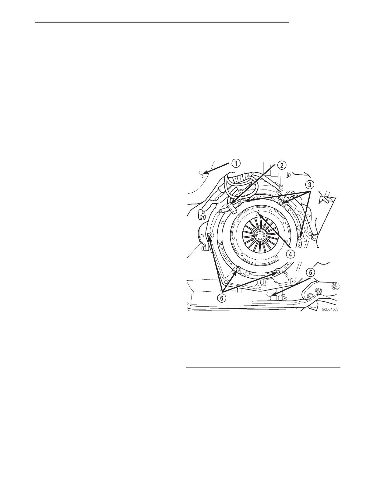
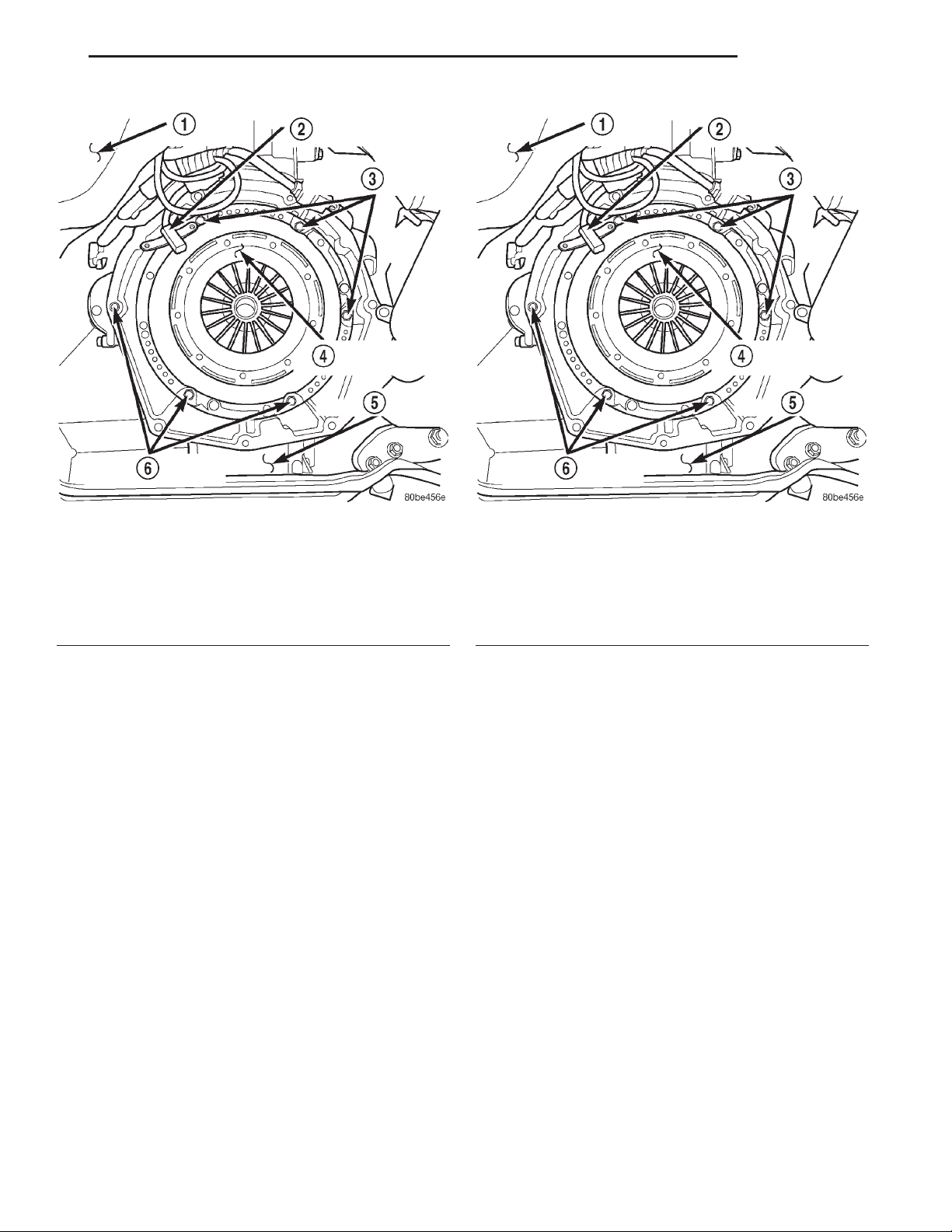
Fig. 1 Clutch Cover (Pressure Plate) View
1 – VEHICLE UNDERBODY
2 – ENGINE SPEED SENSOR
3 – PRESSURE PLATE RETAINING BOLTS
4 – CLUTCH COVER (PRESSURE PLATE)
5 – ENGINE OIL PAN
6 – PRESSURE PLATE RETAINING BOLTS
a star pattern to relieve spring tension equally. This
is necessary to avoid warping the cover.
(4) Remove the clutch cover bolts and remove
cover and disc (Fig. 1).
INSTALLATION
(1) Lightly scuff sand flywheel face with 180 grit
emery cloth. Then clean surface with brake cleaner.
(2) Lightly lubricate the pilot bearing with Mopart
high temperature bearing grease.
Page 2
6 - 2 CLUTCH XJ
REMOVAL AND INSTALLATION (Continued)
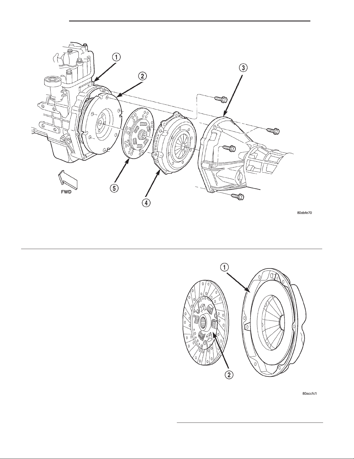
Fig. 2 Clutch Components (VM Diesel)
1 – ENGINE BLOCK
2 – FLYWHEEL
3 – CLUTCH HOUSING AND TRANSMISSION
(3) Check free operation of clutch disc by sliding
disc onto transmission output shaft splines. Disc
should slide onto splines freely without binding.
(4) Position the clutch disc on flywheel. Be sure
side of disc marked “flywheel side” is positioned
against flywheel (Fig. 3). If disc is not marked, be
sure flat side of disc hub is placed toward the flywheel.
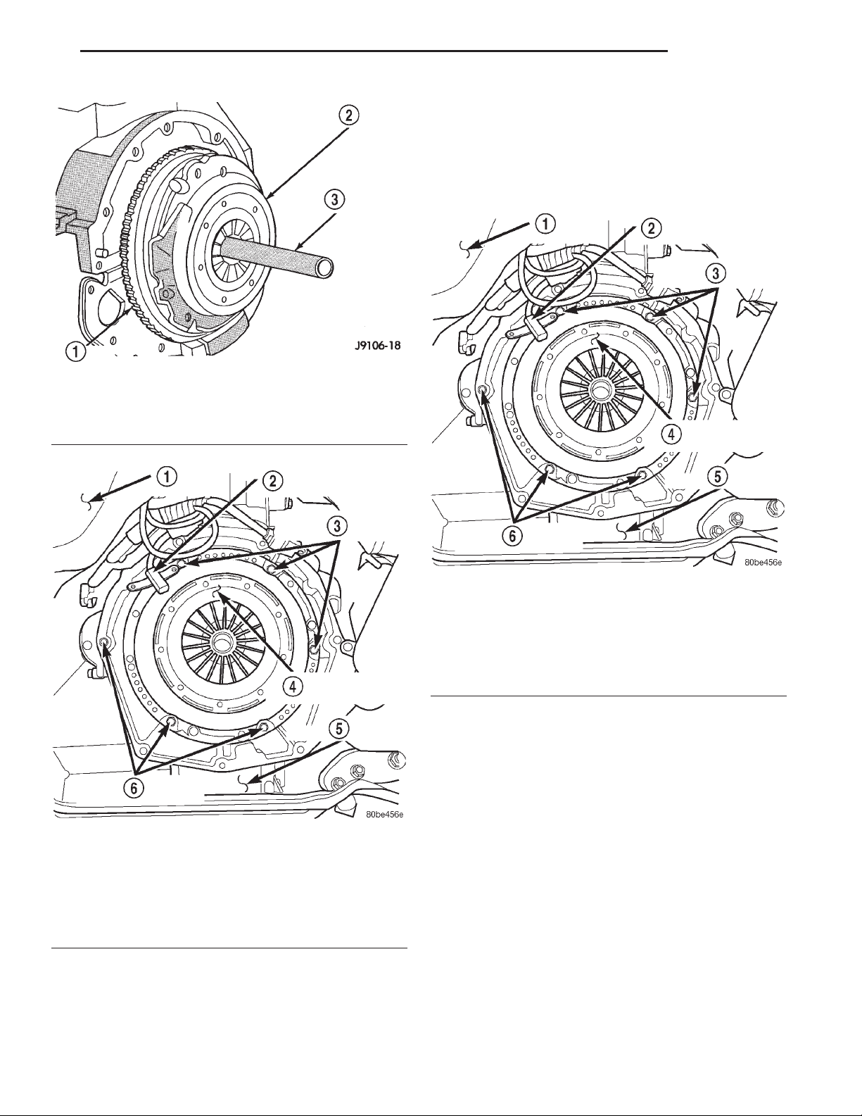
(5) Insert the clutch alignment tool (Fig. 4) in
clutch disc and pilot bearing.
(6) Position the clutch cover over the disc and on
the flywheel (Fig. 5).
(7) Install the clutch cover bolts finger tight (Fig.
5).
(8) Starting with the bolts marked “P” on the cover
first, tighten clutch cover bolts in a star pattern to 50
N·m torque (37 ft. lbs.).
(9) Apply light coat of Mopart high temperature
bearing grease to pilot bearing and splines of transmission input shaft.
CAUTION: Do not over-lubricate as this will result
in grease contamination of the disc.
4 – CLUTCH COVER
5 – CLUTCH DISC
Fig. 3 Clutch Disc Position
1 – INSPECT THIS SURFACE
2 – “FLYWHEEL SIDE” STAMPED ON THIS SURFACE
Page 3
XJ CLUTCH 6 - 3
REMOVAL AND INSTALLATION (Continued)
PILOT BEARING
REMOVAL
(1) Remove the transmission and transfer case.
Refer to Group 21, Transmission and Transfer Case
for procedures.
Fig. 4 Clutch Disc Alignment – Typical
1 – FLYWHEEL
2 – CLUTCH COVER AND DISC
3 – CLUTCH DISC ALIGNMENT TOOL
Fig. 5 Clutch Cover (Pressure Plate) View
1 – VEHICLE UNDERBODY
2 – ENGINE SPEED SENSOR
3 – PRESSURE PLATE RETAINING BOLTS
4 – CLUTCH COVER (PRESSURE PLATE)
5 – ENGINE OIL PAN
6 – PRESSURE PLATE RETAINING BOLTS
(10) Install the transmission and transfer case.
Refer to Group 21, Transmission and Transfer Case
for procedure.
Fig. 6 Clutch Cover (Pressure Plate) View
1 – VEHICLE UNDERBODY
2 – ENGINE SPEED SENSOR
3 – PRESSURE PLATE RETAINING BOLTS
4 – CLUTCH COVER (PRESSURE PLATE)
5 – ENGINE OIL PAN
6 – PRESSURE PLATE RETAINING BOLTS
(2) Remove the clutch cover and disc (Fig. 6). Refer
to clutch cover and disc removal and installation in
this group.
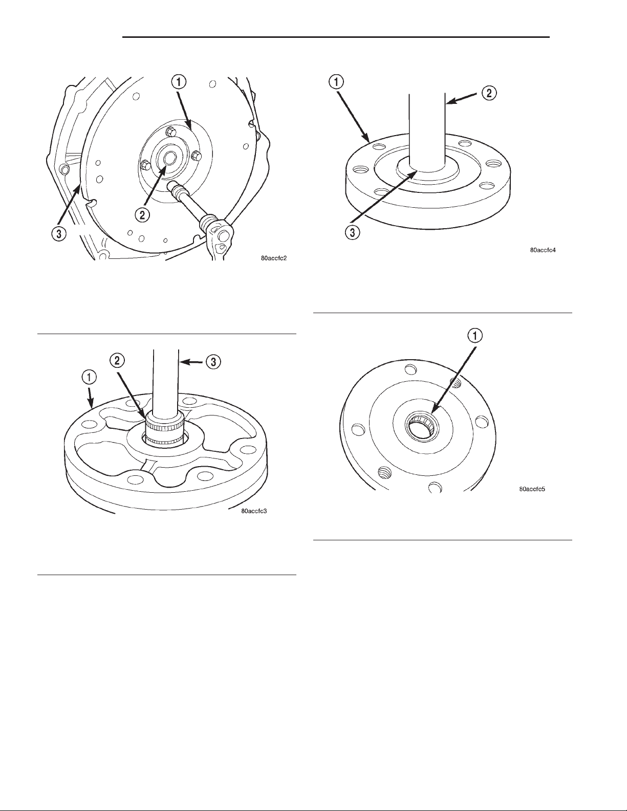
(3) Remove the four bolts that attach the pilot
bearing retainer to the flywheel (Fig. 7).
(4) Remove the pilot bearing retainer.
(5) Support the bearing retainer on two wood
blocks.
(6) Remove the pilot bearing with a suitable sized
socket and extension (Fig. 8). Use mallet to tap bearing out of retainer.
Page 4
6 - 4 CLUTCH XJ
REMOVAL AND INSTALLATION (Continued)
Fig. 7 Pilot Bearing Retainer Bolt Removal/
Installation
1 – RETAINER
2 – PILOT BEARING
3 – FLYWHEEL
Fig. 8 Pilot Bearing Removal
1 – HOUSING
2 – SUITABLE SIZE SOCKET
3 – EXTENSION
INSTALLATION
CAUTION: The bearing can be installed incorrectly
if care is not exercised. Make sure the stamped letters on the bearing will be facing out (toward rear
of vehicle) after installation.
Fig. 9 Pilot Bearing Installation
1 – HOUSING
2 – SPECIAL TOOL C-4171
3 – BEARING
Fig. 10 Pilot Bearing Seated In Retainer
1 – SEAT PILOT BEARING FLUSH WITH LOWER EDGE OF
CHAMFER (IN BORE)
(1) Lightly scuff sand the flywheel surface with
180 grit emery cloth. Clean the surface with Mopart
brake or carburetor cleaner.
(2) Install the new pilot bearing with hammer and
tool handle C-4171. (Fig. 9). Seat the bearing flush
with lower edge of chamfer in retainer bore (Fig. 10).
Reposition the bearing if necessary.
(3) Install the bearing retainer. Torque bolts to 28
N·m (20 ft. lbs.)
(4) Lubricate the pilot bearing with Mopart high
temperature wheel bearing grease.
Page 5
XJ CLUTCH 6 - 5
REMOVAL AND INSTALLATION (Continued)
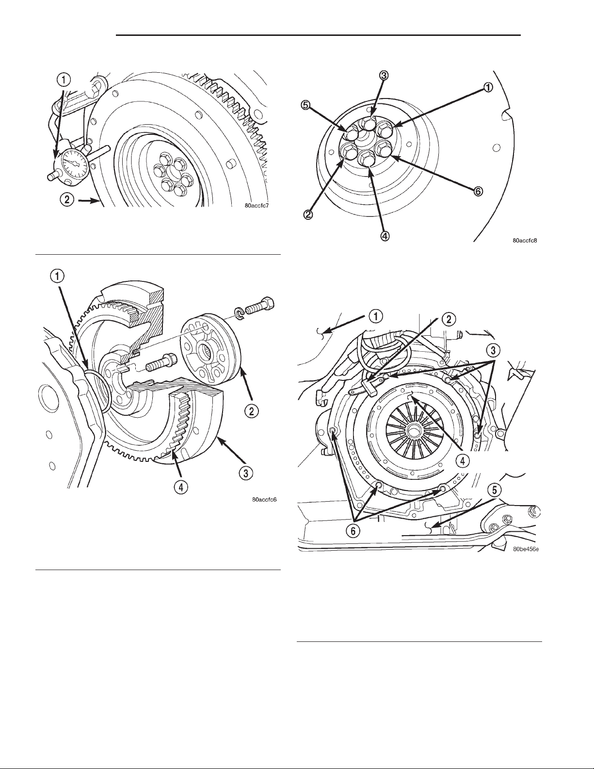
Fig. 11 Clutch Cover (Pressure Plate) View
1 – VEHICLE UNDERBODY
2 – ENGINE SPEED SENSOR
3 – PRESSURE PLATE RETAINING BOLTS
4 – CLUTCH COVER (PRESSURE PLATE)
5 – ENGINE OIL PAN
6 – PRESSURE PLATE RETAINING BOLTS
(5) Install the clutch disc and cover (Fig. 11). Refer
to clutch cover and disc removal and installation in
this group.
(6) Install the transmission and transfer case.
Refer to Group 21, Transmission and Transfer Case
for procedures.
FLYWHEEL
REMOVAL
(1) Remove the transmission and clutch housing.
Refer to Group 21, Transmission and Transfer Case
for procedure.
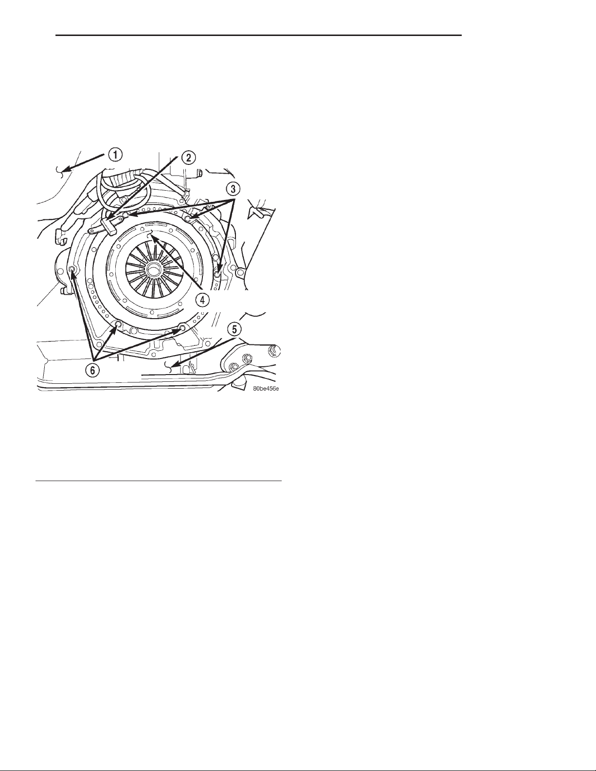
(2) Remove the clutch cover and disc (Fig. 12) as
described in this section.
(3) Remove the bolts that attach pilot bearing
retainer to flywheel.
(4) Remove the pilot bearing and retainer.
(5) Remove the flywheel bolts.
(6) Grasp the flywheel firmly and work it off the
crankshaft flange.
(7) Remove the o-ring from the crankshaft flange,
or the mounting shoulder of the flywheel (Fig. 14).
(8) Clean the flywheel in solvent.
Fig. 12 Clutch Cover (Pressure Plate) View
1 – VEHICLE UNDERBODY
2 – ENGINE SPEED SENSOR
3 – PRESSURE PLATE RETAINING BOLTS
4 – CLUTCH COVER (PRESSURE PLATE)
5 – ENGINE OIL PAN
6 – PRESSURE PLATE RETAINING BOLTS
INSPECTION
Examine the flywheel mounting surfaces, clutch
contact surface, and ring gear. Check condition of flywheel hub and attaching bolts. Replace flywheel if
hub exhibits cracks in the area of attaching bolt
holes. Replace ring gear if the teeth are damaged.
Resurface the flywheel if the clutch contact surface is
scored or rough (refer to flywheel finishing and ring
gear replacement information in this section.
Check flywheel runout if misalignment is suspected. Runout should not exceed 0.08 mm. Measure
flywheel face runout with a dial indicator (Fig. 13).
Mount the indicator on a stud installed in the engine
block or in one of the flywheel attaching bolt holes.
Face runout can be corrected by resurfacing if necessary. Surface grinding equipment is recommended for
this purpose. Stock removal should not exceed 0.25
mm.
INSTALLATION
CAUTION: Use NEW flywheel bolts for the following
procedure.
(1) Clean the crankshaft flange before mounting
the flywheel. Dirt or grease on flange surface may
cock flywheel causing run-out.
Page 6
6 - 6 CLUTCH XJ
REMOVAL AND INSTALLATION (Continued)
Fig. 13 Checking Flywheel Runout
1 – DIAL INDICATOR
2 – FLYWHEEL FACE
Fig. 15 Cross Tightening Method
(c) Loosen one bolt at a time and tighten to 19.6
N•m (14 ft. lbs.) plus 75° using the cross tightening method until completion.
Fig. 14 Flywheel Mounting (VM Diesel)
1 – O-RING
2 – PILOT BEARING HOUSING
3 – FLYWHEEL
4 – STARTER RING GEAR
(2) Install new o-ring in the flywheel mounting
flange (Fig. 14). Use grease to hold the ring in place.
(3) Install the flywheel on the crankshaft and
align the bolt holes.
(4) Install and tighten the new flywheel bolts as
follows:
(a) Lubricate and install the 6 new flywheel
bolts.
(b) Torque the 6 flywheel bolts to 49 N•m (36 ft.
lbs.) starting with one bolt and following with the
opposite one (cross tightening) until completion, in
a clockwise direction (Fig. 15).
Fig. 16 Clutch Cover (Pressure Plate) View
1 – VEHICLE UNDERBODY
2 – ENGINE SPEED SENSOR
3 – PRESSURE PLATE RETAINING BOLTS
4 – CLUTCH COVER (PRESSURE PLATE)
5 – ENGINE OIL PAN
6 – PRESSURE PLATE RETAINING BOLTS
(5) Install the clutch cover and disc (Fig. 16). Refer
to clutch cover and disc removal and installation procedure in this section.
(6) Install the transmission and transfer case.
Refer to Group 21, Transmission and Transfer Case
for removal and installation procedure.
Page 7
XJ CLUTCH 6 - 7
REMOVAL AND INSTALLATION (Continued)
FLYWHEEL RING GEAR
REMOVAL
(1) Remove the transmission and transfer case.
Refer to Group 21, Transmission and Transfer Case
for removal and installation procedures.
Fig. 17 Clutch Cover (Pressure Plate) View
1 – VEHICLE UNDERBODY
2 – ENGINE SPEED SENSOR
3 – PRESSURE PLATE RETAINING BOLTS
4 – CLUTCH COVER (PRESSURE PLATE)
5 – ENGINE OIL PAN
6 – PRESSURE PLATE RETAINING BOLTS
(2) Remove the clutch cover and disc (Fig. 17).
Refer to clutch cover and disc removal and installation in this group.
(3) Remove the flywheel. Refer to flywheel removal
and installation in this group.
(4) Mark position of the old gear for alignment reference. Use a carbide tipped scribe to mark gear location on flywheel.
(5) Wear protective goggles or approved safety
glasses.
(6) Remove the old gear by cutting most of the way
through it at one point. Use an abrasive cut off wheel
for this purpose. Break the ring gear at cut with a
hammer and a cold chisel or punch
(7) Ring gear is shrink fit on flywheel. This means
the gear must be expanded by heating in order to
install it.
NOTE: The method of heating and expanding the
new ring gear is extremely important. Every surface
of the gear must be heated at the same time to produce uniform expansion. An oven or similar
enclosed heating device must be used. Temperature
required for uniform expansion is approximately
350°-375°.
CAUTION: Do not use an oxy/acetylene torch to
remove the old gear, or to heat and expand a new
gear. The high temperature of the torch flame can
cause localized heating that will damage the flywheel. In addition, using the torch to heat a replacement gear will cause uneven heating and
expansion. The torch flame can also anneal the
gear teeth resulting in rapid wear and damage after
installation.
INSTALLATION
(1) Position and install the heated ring gear on the
flywheel:
(a) Wear heat resistant gloves to handle the hot
ring gear.
(b) Align the ring gear on the flywheel evenly.
(c) Use hammer and brass drift to tap ring gear
onto the flywheel.
(d) Seat the ring gear on flywheel
(2) Allow the ring gear to cool down before installation on the engine. Place flywheel on work bench
and let it cool in normal shop air.
(3) Install the flywheel and torque bolts. Refer to
flywheel removal and installation in this group.
(4) Install the clutch cover and disc (Fig. 18). Refer
to clutch cover and disc removal and installation in
this group.
(5) Install the transmission and transfer case.
Refer to Group 21, Transmission and Transfer Case
for removal and installation procedures.
CAUTION: Do not use water or compressed air to
cool the flywheel. The rapid cooling produced by
water or compressed air will distort or crack the
new gear.
Page 8
6 - 8 CLUTCH XJ
REMOVAL AND INSTALLATION (Continued)
SPECIFICATIONS
SPECIFICATIONS
DESCRIPTION TORQUE
Clutch Cover to Flywheel
Bolts ................... 50N·m(37ft.lbs.)
Clutch Housing to Transmission
Bolts ................... 46N·m(34ft.lbs.)
Flywheel to Crankshaft
Bolts ..... Seeremoval and installation procedure.
Pilot Bearing Retainer to Flywheel/Crankshaft
Bolts ................... 28N·m(20ft.lbs.)
Clutch Housing to Engine
Top (2) Bolts .............. 37N·m(27ft.lbs.)
Middle (2) Bolts ........... 58N·m(43ft.lbs.)
Bottom (2) Bolts ........... 75N·m(55ft.lbs.)
SPECIAL TOOLS
Fig. 18 Clutch Cover (Pressure Plate) View
1 – VEHICLE UNDERBODY
2 – ENGINE SPEED SENSOR
3 – PRESSURE PLATE RETAINING BOLTS
4 – CLUTCH COVER (PRESSURE PLATE)
5 – ENGINE OIL PAN
6 – PRESSURE PLATE RETAINING BOLTS
SPECIAL TOOLS
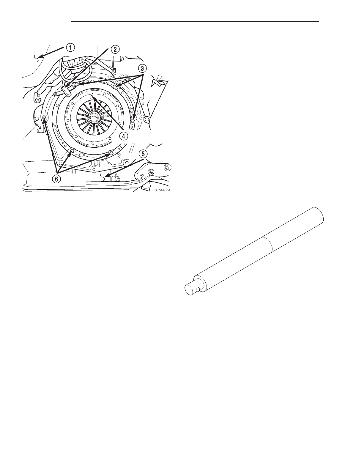
Universal Handle—C-4171
 Loading...