

Page 1
XJ CLUTCH 6 - 1
CLUTCH
TABLE OF CONTENTS
page page
DESCRIPTION AND OPERATION
CLUTCH ................................1
FLYWHEEL ..............................2
CLUTCH DISC............................2
CLUTCH PRESSURE PLATE.................2
CLUTCH RELEASE BEARING ................3
HYDRAULIC CLUTCH LINKAGE ..............4
DIAGNOSIS AND TESTING
SAFETY PRECAUTIONS ....................4
INSTALLATION METHODS AND PARTS
USAGE................................4
CLUTCH DIAGNOSTIC INFORMATION.........4
CLUTCH CONTAMINATION..................6
IMPROPER CLUTCH RELEASE OR
ENGAGEMENT ..........................6
CLUTCH MISALIGNMENT...................6
CLUTCH HOUSING MISALIGNMENT ..........6
DESCRIPTION AND OPERATION
CLUTCH
CLUTCH FLYWHEEL RUNOUT ...............6
CLUTCH COVER AND DISC RUNOUT .........7
CLUTCH DIAGNOSIS CHARTS...............7
SERVICE PROCEDURES
CLUTCH COMPONENT LUBRICATION .........9
CLUTCH LINKAGE FLUID...................9
CLUTCH FLUID LEVEL....................10
FLYWHEEL .............................10
REMOVAL AND INSTALLATION
CLUTCH COVER AND DISC ................11
RELEASE BEARING ......................12
PILOT BEARING .........................12
CLUTCH HOUSING.......................13
CLUTCH HYDRAULIC LINKAGE .............13
SPECIFICATIONS
TORQUE ...............................15
DESCRIPTION
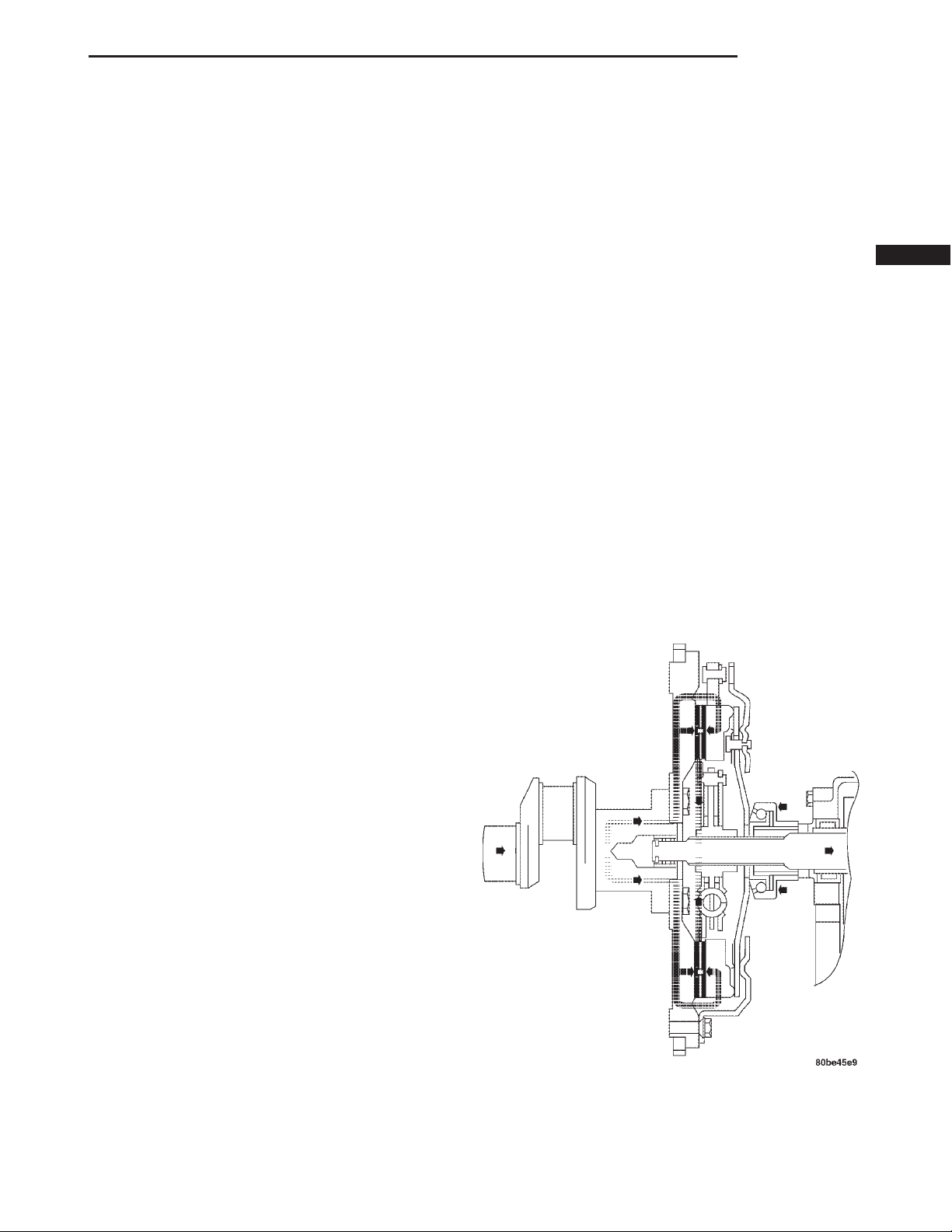
The clutch mechanism consists of a flywheel, a single, dry-type disc, and a diaphragm style clutch cover
(Fig. 1). A hydraulic linkage is used to operate the
clutch release bearing and fork. The flywheel is
bolted to the rear flange of the crankshaft. The
clutch pressure plate is bolted to the flywheel with
the clutch disc located between these two components. The clutch system provides the mechanical,
but still easily detachable, link between the engine
and the transmission. The system is designed to
ensure that the full torque output of the engine is
transfered to the transmission while isolating the
transmission from the engine firing pulses to minimize concerns such as gear rattle.
OPERATION
Leverage, clamping force, and friction are what
make the clutch work. The disc serves as the friction
element and a diaphragm spring and pressure plate
provide the clamping force. The clutch pedal, hydraulic linkage, release lever and bearing provide the
leverage.
Fig. 1 Engine Powerflow
Page 2
6 - 2 CLUTCH XJ
DESCRIPTION AND OPERATION (Continued)
The clutch master cylinder push rod is connected
to the clutch pedal. When the clutch pedal is
depressed, the slave cylinder is operated by the
clutch master cylinder mounted on the dash panel.
The release fork is actuated by the hydraulic slave
cylinder mounted on the transmission housing. The
release bearing is operated by a release fork pivoting
on a ball stud mounted in the transmission housing.
The release bearing then depresses the pressure
plate spring fingers, thereby releasing pressure on
the clutch disc and allowing the engine crankshaft to
spin independently of the transmission input shaft
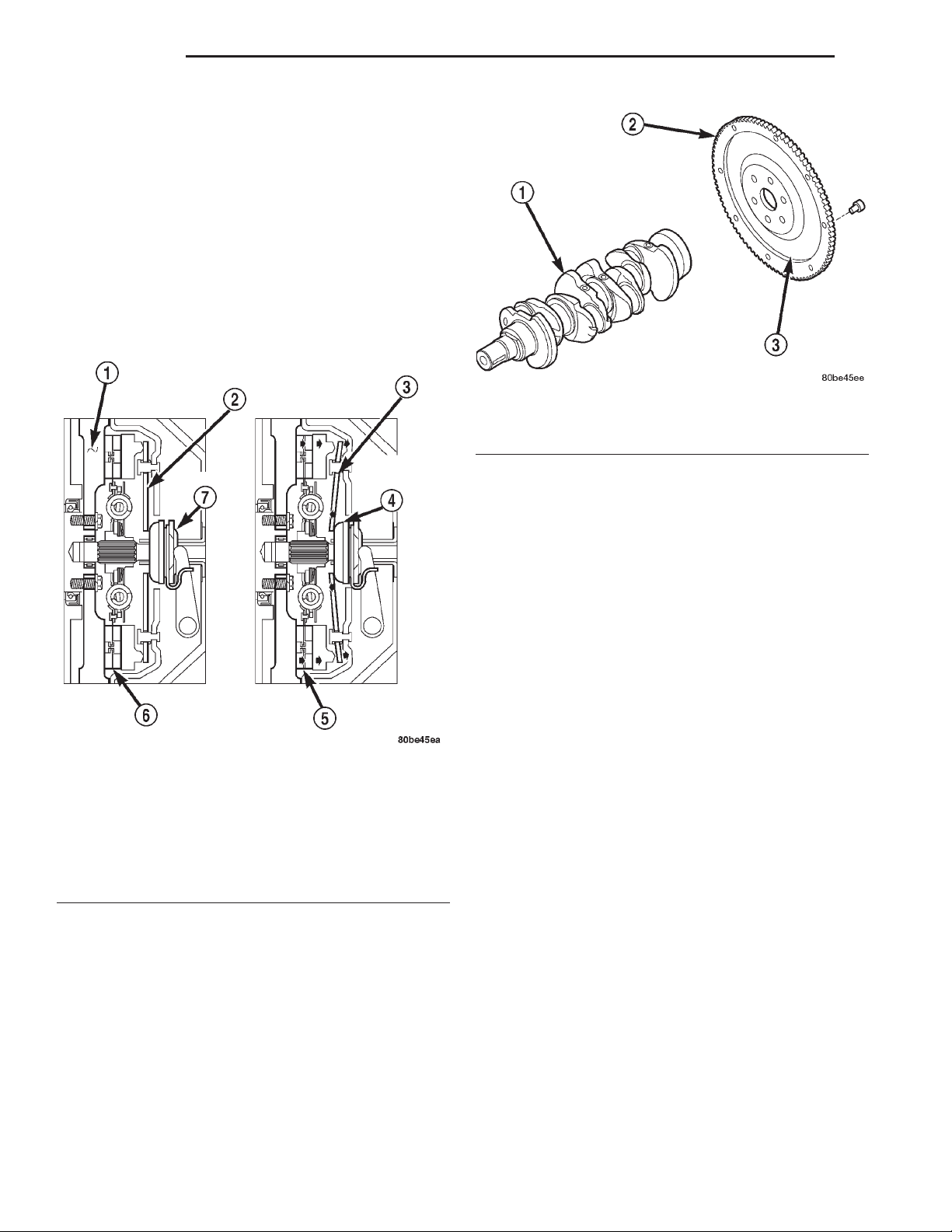
(Fig. 2).
Fig. 3 Flywheel
1 – CRANKSHAFT
2 – RING GEAR
3 – FLYWHEEL
OPERATION
The flywheel serves to dampen the engine firing
pulses. The heavy weight of the flywheel relative to
the rotating mass of the engine components serves to
stabilize the flow of power to the remainder of the
drivetrain. The crankshaft has the tendency to
attempt to speed up and slow down in response to
the cylinder firing pulses. The flywheel dampens
these impulses by absorbing energy when the crankshaft speeds and releasing the energy back into the
system when the crankshaft slows down.
Fig. 2 Clutch Operation
1 – FLYWHEEL
2 – PRESSURE PLATE FINGERS
3 – PIVOT POINT
4 – RELEASE BEARING PUSHED IN
5 – CLUTCH DISC ENGAGED
6 – CLUTCH DISC ENGAGED
7 – RELEASE BEARING
FLYWHEEL
DESCRIPTION
The flywheel (Fig. 3) is a heavy plate bolted to the
rear of the crankshaft. The flywheel incorporates the
ring gear around the outer circumference to mesh
with the starter to permit engine cranking. The rear
face of the flywheel serves as the driving member to
the clutch disc.
CLUTCH DISC
DESCRIPTION
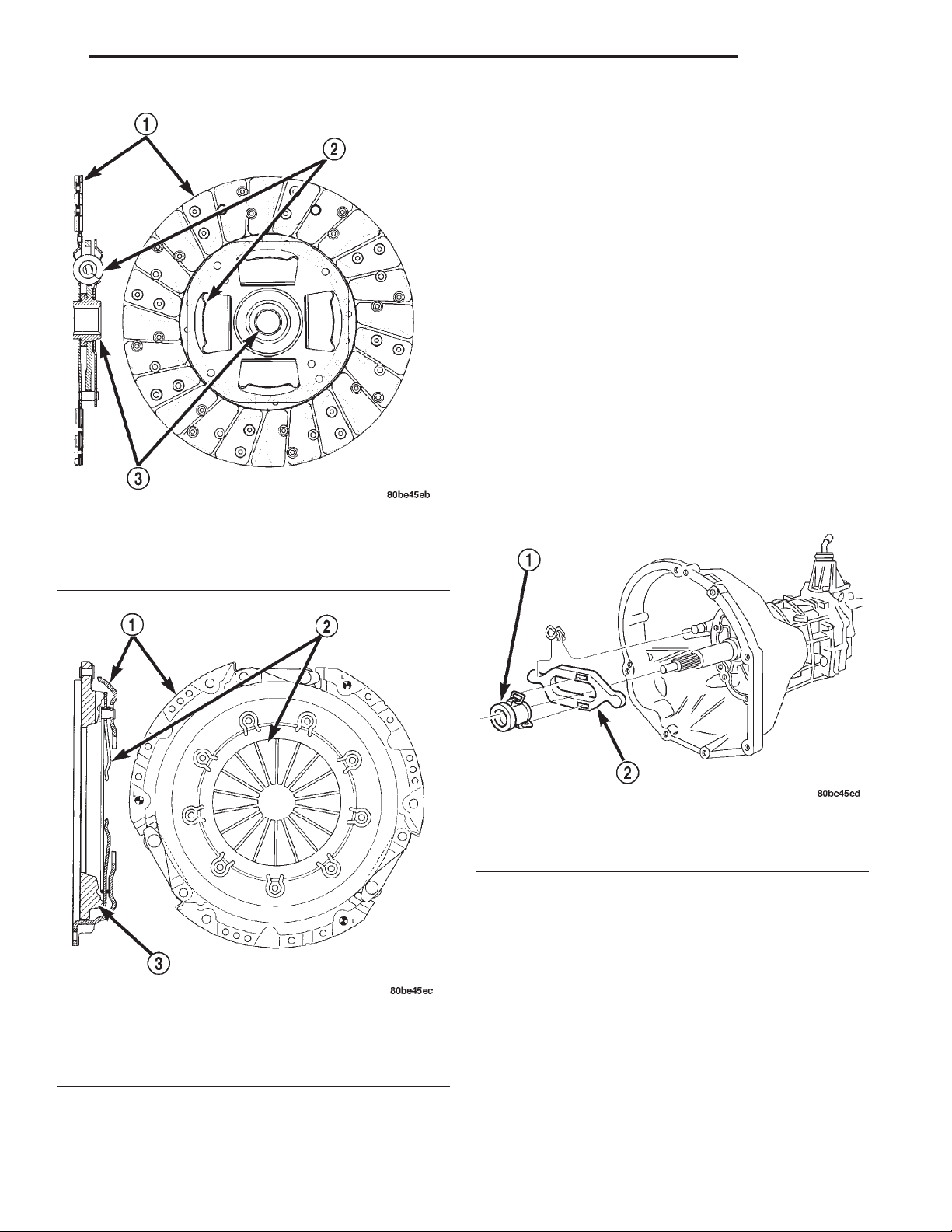
The clutch disc friction material is riveted to the
disc hub (Fig. 4). The hub bore is splined for installation on the transmission input shaft. The clutch disc
has cushion springs in the disc hub to dampen disc
vibrations during application and release of the clutch.
OPERATION
The clutch disc is held onto the surface of the flywheel by the force exerted by the pressure plate’s diaphragm spring. The friction material of the clutch disc
then transfers the engine torque from the flywheel and
pressure plate to the input shaft of the transmission.
CLUTCH PRESSURE PLATE
DESCRIPTION
The clutch pressure plate assembly is a diaphragm
type with a one-piece spring and multiple release fingers (Fig. 5). The pressure plate release fingers are
preset during manufacture and are not adjustable.
The assembly also contains the cover, pressure plate,
and fulcrum components.
Page 3
XJ CLUTCH 6 - 3
DESCRIPTION AND OPERATION (Continued)
OPERATION
The clutch pressure plate assembly clamps the
clutch disc against the flywheel. When the release
bearing is depressed by the shift fork, the pressure
exerted on the clutch disc by the pressure plate
spring is decreased. As additional force is applied,
the bearing presses the diaphragm spring fingers
inward on the fulcrums. This action moves the pressure plate rearward relieving clamp force on the disc.
The clutch disc is disengaged and freewheeling at
this point.
CLUTCH RELEASE BEARING
DESCRIPTION
A conventional release bearing (Fig. 6) is used to
engage and disengage the clutch pressure plate
assembly. The clutch release bearing is mounted on
the transmission front bearing retainer. The bearing
is attached to the release fork, which moves the bearing into contact with the clutch cover diaphragm
Fig. 4 Clutch Disc-Typical
1 – FACING MATERIAL
2 – DAMPER SPRINGS
3 – HUB
spring.
Fig. 5 Clutch Pressure Plate-Typical
1 – COVER
2 – RELEASE FINGERS
3 – PRESSURE PLATE
Fig. 6 Clutch Release Bearing
1 – RELEASE BEARING
2 – RELEASE FORK
OPERATION
The release bearing is operated by a release fork in
the clutch housing. Slave cylinder force causes the
release lever to move the release bearing into contact
with the diaphragm spring. As additional force is
applied, the bearing presses the diaphragm spring
fingers inward on the fulcrums. This action moves
the pressure plate rearward relieving clamp force on
the disc. Releasing pedal pressure removes clutch
hydraulic pressure. The release bearing then moves
away from the diaphragm spring which allows the
pressure plate to exert clamping force on the clutch
disc.
Page 4
6 - 4 CLUTCH XJ
DESCRIPTION AND OPERATION (Continued)
HYDRAULIC CLUTCH LINKAGE
DESCRIPTION
The hydraulic linkage consists of a clutch master
cylinder with integral reservoir, a clutch slave cylinder and an interconnecting fluid line (Fig. 7).
The clutch master cylinder push rod is connected to
the clutch pedal. The slave cylinder push rod is connected to the clutch release fork. The master cylinder is
mounted on the driver side of the dash panel adjacent
to the brake master cylinder and booster assembly.
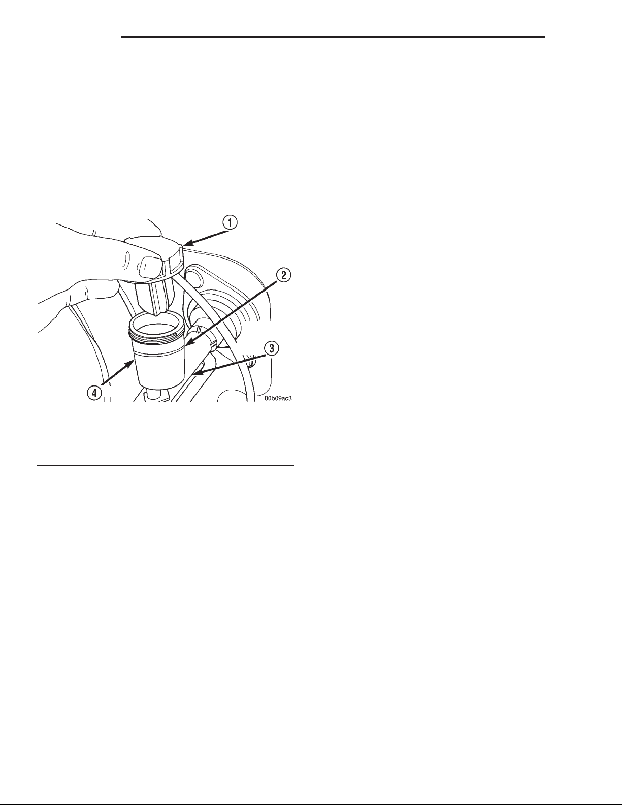
Fig. 7 Clutch Master Cylinder
1 – CAP
2 – FILL LINE
3 – CLUTCH MASTER CYLINDER
4 – RESERVOIR
OPERATION
The clutch linkage uses hydraulic pressure to operate the clutch. Depressing the clutch pedal develops
fluid pressure in the clutch master cylinder. This
pressure is transmitted to the slave cylinder through
a connecting line. In turn, the slave cylinder operates
the clutch release lever.
Slave cylinder force causes the release lever to
move the release bearing into contact with the diaphragm spring. As additional force is applied, the
bearing presses the diaphragm spring fingers inward
on the fulcrums. This action moves the pressure
plate rearward relieving clamp force on the disc.
DIAGNOSIS AND TESTING
SAFETY PRECAUTIONS
WARNING: EXERCISE CARE WHEN SERVICING
CLUTCH COMPONENTS. FACTORY INSTALLED
CLUTCH DISCS DO NOT CONTAIN ASBESTOS
FIBERS. DUST AND DIRT ON CLUTCH PARTS MAY
CONTAIN ASBESTOS FIBERS FROM AFTERMARKET
COMPONENTS. BREATHING EXCESSIVE CONCENTRATIONS OF THESE FIBERS CAN CAUSE SERIOUS
BODILY HARM. WEAR A RESPIRATOR DURING SERVICE AND NEVER CLEAN CLUTCH COMPONENTS
WITH COMPRESSED AIR OR WITH A DRY BRUSH.
EITHER CLEAN THE COMPONENTS WITH A WATER
DAMPENED RAGS OR USE A VACUUM CLEANER
SPECIFICALLY DESIGNED FOR REMOVING ASBESTOS FIBERS AND DUST. DO NOT CREATE DUST BY
SANDING A CLUTCH DISC. REPLACE THE DISC IF
THE FRICTION MATERIAL IS DAMAGED OR CONTAMINATED. DISPOSE OF ALL DUST AND DIRT CONTAINING ASBESTOS FIBERS IN SEALED BAGS OR
CONTAINERS. THIS WILL HELP MINIMIZE EXPOSURE
TO YOURSELF AND TO OTHERS. FOLLOW ALL RECOMMENDED SAFETY PRACTICES PRESCRIBED BY
THE OCCUPATIONAL SAFETY AND HEALTH ADMINISTRATION (OSHA) AND THE ENVIRONMENTAL
SAFETY AGENCY (EPA), FOR THE HANDLING AND
DISPOSAL OF PRODUCTS CONTAINING ASBESTOS.
INSTALLATION METHODS AND PARTS USAGE
Distortion of clutch components during installation
and the use of non-standard components are common
causes of clutch malfunction.
Improper clutch cover bolt tightening can distort
the cover. The usual result is clutch grab, chatter
and rapid wear. Tighten the cover bolts as described
in Removal and Installation section.
An improperly seated flywheel and/or clutch housing are additional causes of clutch failure. Improper
seating will produce misalignment and additional
clutch problems.
The use of non-standard or low quality parts will
also lead to problems and wear. Use recommended
factory quality parts to avoid comebacks.
A cocked pilot bearing is another cause of clutch
noise, drag, hard shifting, and rapid bearing wear.
Always use an alignment tool to install a new bearing. This practice helps avoid cocking the bearing
during installation.
CLUTCH DIAGNOSTIC INFORMATION
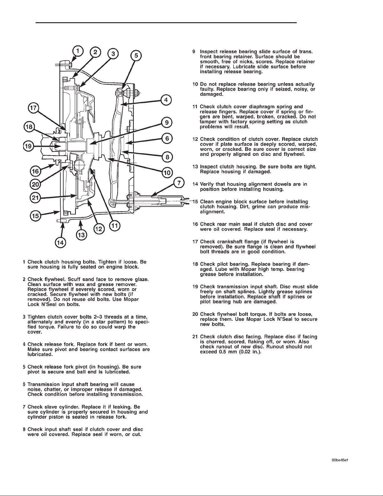
Unless the cause of a clutch problem is obvious, accurate problem diagnosis will usually require a road test to
confirm a problem. Component inspection (Fig. 8) will
then be required to determine the actual problem cause.
During a road test, drive the vehicle at normal
speeds. Shift the transmission through all gear
ranges and observe clutch action. If chatter, grab,
slip, or improper release is experienced, remove and
inspect the clutch components. However, if the problem is noise or hard shifting, further diagnosis may
be needed as the transmission or another driveline
component may be at fault. Careful observation during the test will help narrow the problem area.
Page 5
XJ CLUTCH 6 - 5
DIAGNOSIS AND TESTING (Continued)
Fig. 8 Clutch Components And Inspection
Page 6

6 - 6 CLUTCH XJ
DIAGNOSIS AND TESTING (Continued)
CLUTCH CONTAMINATION
Fluid contamination is a frequent cause of clutch
malfunctions. Oil, water, or clutch fluid on the clutch
disc and pressure plate surfaces will cause chatter,
slip and grab.
During inspection, note if any components are contaminated with oil, hydraulic fluid, or water/road
splash.
Oil contamination indicates a leak at either the
rear main seal or transmission input shaft. Oil leakage produces a residue of oil on the housing interior
and on the clutch cover and flywheel. Heat buildup
caused by slippage between the cover, disc and flywheel, can sometimes bake the oil residue onto the
components. The glaze-like residue ranges in color
from amber to black.
Road splash contamination means dirt/water is
entering the clutch housing due to loose bolts, housing cracks, or through hydraulic line openings. Driving through deep water puddles can force water/road
splash into the housing through such openings.
Clutch fluid leaks are usually from damaged slave
cylinder push rod seals. This type of leak can only be
confirmed by visual inspection.
IMPROPER CLUTCH RELEASE OR ENGAGEMENT
Clutch release or engagement problems are caused
by wear, or damage to one or more clutch components. A visual inspection of the release components
will usually reveal the problem part.
Release problems can result in hard shifting and
noise. Items to look for are: leaks at the clutch cylinders and interconnecting line; loose slave cylinder
bolts; worn/loose release fork and pivot stud; damaged release bearing; and a worn clutch disc, or pressure plate.
Normal condensation in vehicles that are stored or
out of service for long periods of time can generate
enough corrosion to make the disc stick to the flywheel, or pressure plate. If this condition is experienced, correction only requires that the disc be
loosened manually through the inspection plate opening.
Engagement problems usually result in slip, chatter/shudder, and noisy operation. The primary causes
are clutch disc contamination; clutch disc wear; misalignment, or distortion; flywheel damage; or a combination of the foregoing. A visual inspection is
required to determine the part actually causing the
problem.
CLUTCH MISALIGNMENT
Clutch components must be in proper alignment
with the crankshaft and transmission input shaft.
Misalignment caused by excessive runout or warpage
of any clutch component will cause grab, chatter and
improper clutch release.
CLUTCH HOUSING MISALIGNMENT
Clutch housing alignment is important to proper
clutch operation. The housing maintains alignment
between the crankshaft and transmission input
shaft. Misalignment can cause clutch noise, hard
shifting, incomplete release and chatter. It can also
result in premature wear of the pilot bearing, cover
release fingers and clutch disc. In severe cases, misalignment can also cause premature wear of the
transmission input shaft and front bearing.
Housing misalignment is generally caused by
incorrect seating on the engine or transmission, loose
housing bolts, missing alignment dowels, or housing
damage. Infrequently, misalignment may also be
caused by housing mounting surfaces that are not
completely parallel. Misalignment can be corrected
with shims.
CLUTCH FLYWHEEL RUNOUT
Check flywheel runout whenever misalignment is
suspected. Flywheel runout should not exceed 0.08
mm (0.003 in.). Measure runout at the outer edge of
the flywheel face with a dial indicator. Mount the
indicator on a stud installed in place of one of the flywheel bolts.
Common causes of runout are:
• heat warpage
• improper machining
• incorrect bolt tightening
• improper seating on crankshaft flange shoulder
• foreign material on crankshaft flange
Flywheel machining is not recommended. The flywheel clutch surface is machined to a unique contour
and machining will negate this feature. However,
minor flywheel scoring can be cleaned up by hand
with 180 grit emery, or with surface grinding equipment. Remove only enough material to reduce scoring (approximately 0.001 - 0.003 in.). Heavy stock
removal is not recommended. Replace the flywheel
if scoring is severe and deeper than 0.076 mm (0.003
in.). Excessive stock removal can result in flywheel
cracking or warpage after installation; it can also
weaken the flywheel and interfere with proper clutch
release.
Clean the crankshaft flange before mounting the
flywheel. Dirt and grease on the flange surface may
cock the flywheel causing excessive runout. Use new
bolts when remounting a flywheel and secure the
bolts with Mopart Lock And Seal. Tighten flywheel
bolts to specified torque only. Overtightening can distort the flywheel hub causing runout.
Page 7
XJ CLUTCH 6 - 7
DIAGNOSIS AND TESTING (Continued)
CLUTCH COVER AND DISC RUNOUT
Check the clutch disc before installation. Axial
(face) runout of a new disc should not exceed 0.50
mm (0.020 in.). Measure runout about 6 mm (1/4 in.)
from the outer edge of the disc facing. Obtain
another disc if runout is excessive.
Check condition of the clutch before installation. A
warped cover or diaphragm spring will cause grab
and incomplete release or engagement. Be careful
when handling the cover and disc. Impact can distort
the cover, diaphragm spring, release fingers and the
hub of the clutch disc.
Use an alignment tool when positioning the disc on
the flywheel. The tool prevents accidental misalignment which could result in cover distortion and disc
damage.
A frequent cause of clutch cover distortion (and
consequent misalignment) is improper bolt tightening.
DIAGNOSIS CHART
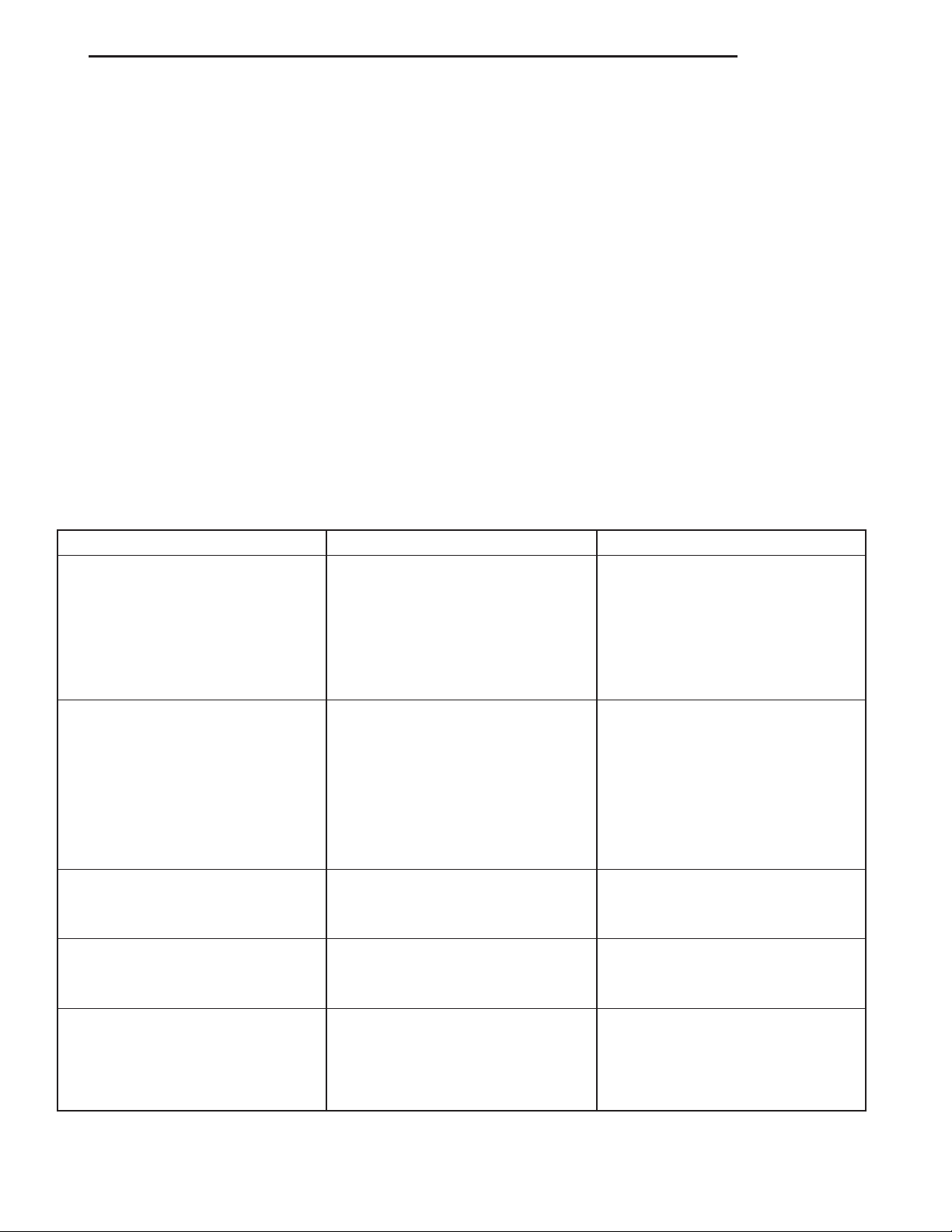
CONDITION POSSIBLE CAUSES CORRECTION
CLUTCH DIAGNOSIS CHARTS
The clutch inspection chart (Fig. 8) outlines items
to be checked before and during clutch installation.
Use the chart as a check list to help avoid overlooking potential problem sources during service operations.
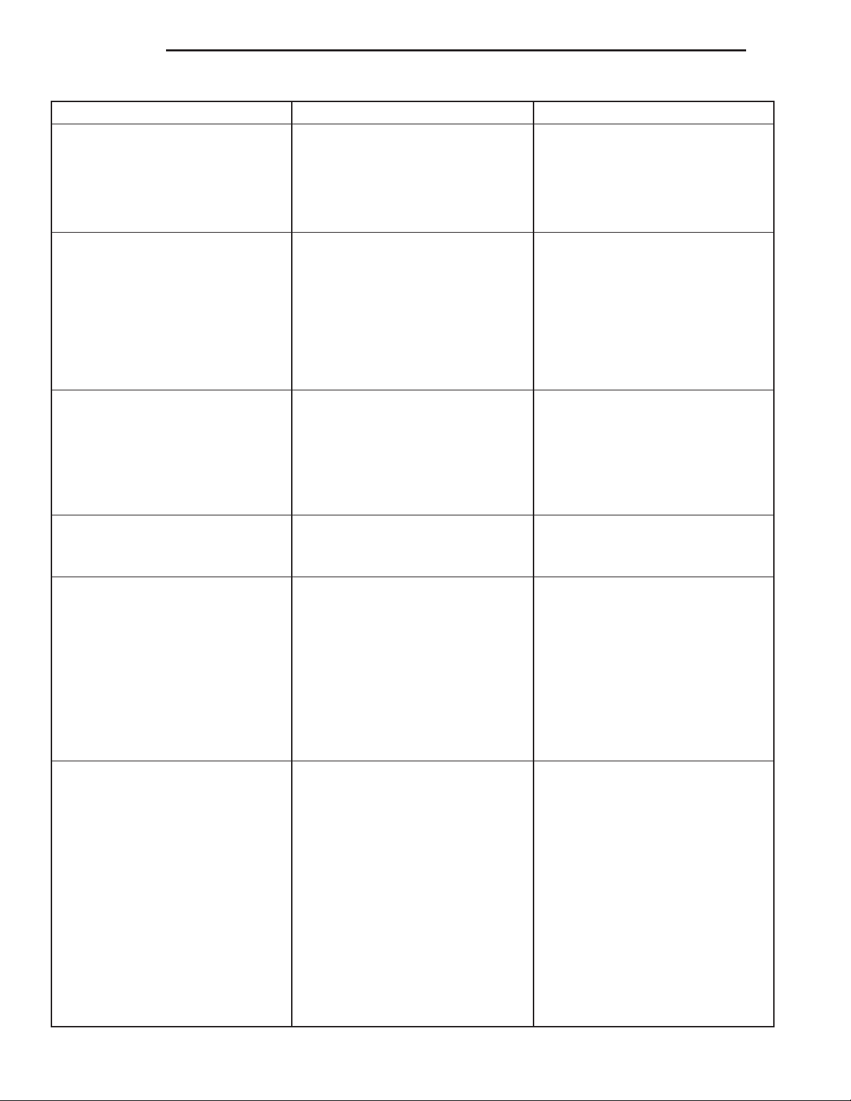
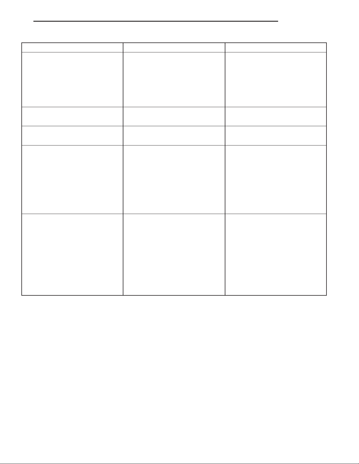
The diagnosis charts describe common clutch problems, causes and correction. Fault conditions are
listed at the top of each chart. Conditions, causes and
corrective action are outlined in the indicated columns.
The charts are provided as a convenient reference
when diagnosing faulty clutch operation.
Disc facing worn out 1. Normal wear. 1. Replace cover and disc.
Clutch disc facing contaminated with
oil, grease, or clutch fluid.
Clutch is running partially
disengaged.
Flywheel below minimum thickness
specification.
2. Driver frequently rides (slips) the
clutch. Results in rapid overheating
and wear.
3. Insufficient clutch cover
diaphragm spring tension.
1. Leak at rear main engine seal or
transmission input shaft seal.
2. Excessive amount of grease
applied to the input shaft splines.
3. Road splash, water entering
housing.
4. Slave cylinder leaking. 4. Replace hydraulic clutch linkage.
1. Release bearing sticking or
binding and does not return to the
normal running position.
1. Improper flywheel machining.
Flywheel has excessive taper or
excessive material removal.
2. Replace cover and disc.
3. Replace cover and disc.
1. Replace appropriate seal.
2. Remove grease and apply the
correct amount of grease.
3. Replace clutch disc. Clean clutch
cover and reuse if in good condition.
1. Verify failure. Replace the release
bearing and transmission front
bearing retainer as necessary.
1. Replace flywheel.
Clutch disc, cover and/or diaphragm
spring warped or distorted.
1. Rough handling. Impact bent
cover, spring, or disc.
2. Improper bolt tightening
procedure.
1. Replace disc or cover as
necessary.
2. Tighten clutch cover using proper
procedure.
Page 8
6 - 8 CLUTCH XJ
DIAGNOSIS AND TESTING (Continued)
CONDITION POSSIBLE CAUSES CORRECTION
Facing on flywheel side of disc torn,
gouged, or worn.
Clutch disc facing burnt. Flywheel
and cover pressure plate surfaces
heavily glazed.
Clutch disc binds on input shaft
splines.
Clutch disc rusted to flywheel and/or
pressure plate.
1. Flywheel surface scored or
nicked.
2. Clutch disc sticking or binding on
transmission input shaft.
1. Frequent operation under high
loads or hard acceleration
conditions.
2. Driver frequently rides (slips)
clutch. Results in rapid wear and
overheating of disc and cover.
1. Clutch disc hub splines damaged
during installation.
2. Input shaft splines rough,
damaged, or corroded.
1. Clutch not used for and extended
period of time (e.g. long term
vehicle storage).
2. Correct surface condition if
possible. Replace flywheel and disc
as necessary.
2. Inspect components and
correct/replace as necessary.
1. Correct condition of flywheel and
pressure plate surface. Replace
clutch cover and disc. Alert driver to
problem cause.
2. Correct condition of flywheel and
pressure plate surface. Replace
clutch cover and disc. Alert driver to
problem cause.
1. Clean, smooth, and lubricate hub
splines if possible. Replace disc if
necessary.
2. Clean, smooth, and lubricate
shaft splines if possible. Replace
input shaft if necessary.
1. Sand rusted surfaces with 180
grit sanding paper. Replace clutch
cover and flywheel if necessary.
Pilot bearing seized, loose, or rollers
are worn.
Clutch will not disengage properly. 1. Low clutch fluid level. 1. Replace hydraulic linkage
1. Bearing cocked during
installation.
2. Bearing defective. 2. Install and lubricate a new
3. Bearing not lubricated. 3. Install and lubricate a new
4. Clutch misalignment. 4. Inspect clutch and correct as
2. Clutch cover loose. 2. Follow proper bolt tightening
3. Clutch disc bent or distorted. 3. Replace clutch disc.
4. Clutch cover diaphragm spring
bent or warped.
5. Clutch disc installed backwards. 5. Remove and install clutch disc
6. Release fork bent or fork pivot
loose or damaged.
7. Clutch master or slave cylinder
failure.
1. Install and lubricate a new
bearing.
bearing.
bearing.
necessary. Install and lubricate a
new bearing.
assembly.
procedure.
4. Replace clutch cover.
correctly.
6. Replace fork or pivot as
necessary.
7. Replace hydraulic linkage
assembly.
Page 9
XJ CLUTCH 6 - 9
DIAGNOSIS AND TESTING (Continued)
CONDITION POSSIBLE CAUSES CORRECTION
Clutch pedal squeak. 1. Pivot pin loose. 1. Tighten pivot pin if possible.
Replace clutch pedal if necessary.
2. Master cylinder bushing not
lubricated.
3. Pedal bushings worn out or
cracked.
Clutch master or slave cylinder
plunger dragging andør binding
Release bearing is noisy. 1. Release bearing defective or
Contact surface of release bearing
damaged.
Partial engagement of clutch disc.
One side of disc is worn and the
other side is glazed and lightly
worn.
1. Master or slave cylinder
components worn or corroded.
damaged.
1. Clutch cover incorrect or release
fingers bent or distorted.
2. Release bearing defective or
damaged.
3. Release bearing misaligned. 3. Check and correct runout of
1. Clutch pressure plate position
incorrect.
2. Clutch cover, spring, or release
fingers bent or distorted.
3. Clutch disc damaged or
distorted.
4. Clutch misalignment. 4. Check alignment and runout of
2. Lubricate master cylinder
bushing.
3. Replace and lubricate bushings.
1. Replace clutch hydraulic linkage
assembly.
1. Replace release bearing.
1. Replace clutch cover and release
bearing.
2. Replace the release bearing.
clutch components. Check front
bearing sleeve for damage/
alignment. Repair as necessary.
1. Replace clutch disc and cover.
2. Replace clutch disc and cover.
2. Replace clutch disc.
flywheel, disc, pressure plate, andør
clutch housing. Correct as
necessary.
SERVICE PROCEDURES
CLUTCH COMPONENT LUBRICATION
Proper clutch component lubrication is important
to satisfactory operation. Using the correct lubricant
and not over lubricating are equally important. Apply
recommended lubricant sparingly to avoid disc and
pressure plate contamination.
Clutch and transmission components requiring
lubrication are:
• Pilot bearing.
• Release lever pivot ball stud.
• Release lever contact surfaces.
• Release bearing bore.
• Clutch disc hub splines.
• Clutch pedal pivot shaft bore.
• Clutch pedal bushings.
• Input shaft splines.
• Input shaft pilot hub.
• Transmission front bearing retainer slide sur-
face.
NOTE: Never apply grease to any part of the clutch
cover, or disc.
RECOMMENDED LUBRICANTS
Use Mopart multi-purpose grease for the clutch
pedal bushings and pivot shaft. Use Mopart high
temperature grease (or equivalent) for all other lubrication requirements. Apply recommended amounts
and do not over lubricate.
CLUTCH LINKAGE FLUID
If inspection or diagnosis indicates additional fluid
may be needed, use Mopart brake fluid, or an equiv-
Page 10
6 - 10 CLUTCH XJ
SERVICE PROCEDURES (Continued)
alent meeting standards SAE J1703 and DOT 3. Do
not use any other type of fluid.
CLUTCH FLUID LEVEL
The clutch fluid reservoir, master cylinder, slave
cylinder and fluid lines are pre-filled with fluid at
the factory during assembly operations.
The hydraulic system should not require additional
fluid under normal circumstances. In fact, the reser-
voir fluid level will actually increase as normal
clutch wear occurs. For this reason, it is important to avoid overfilling, or removing fluid from
the reservoir.
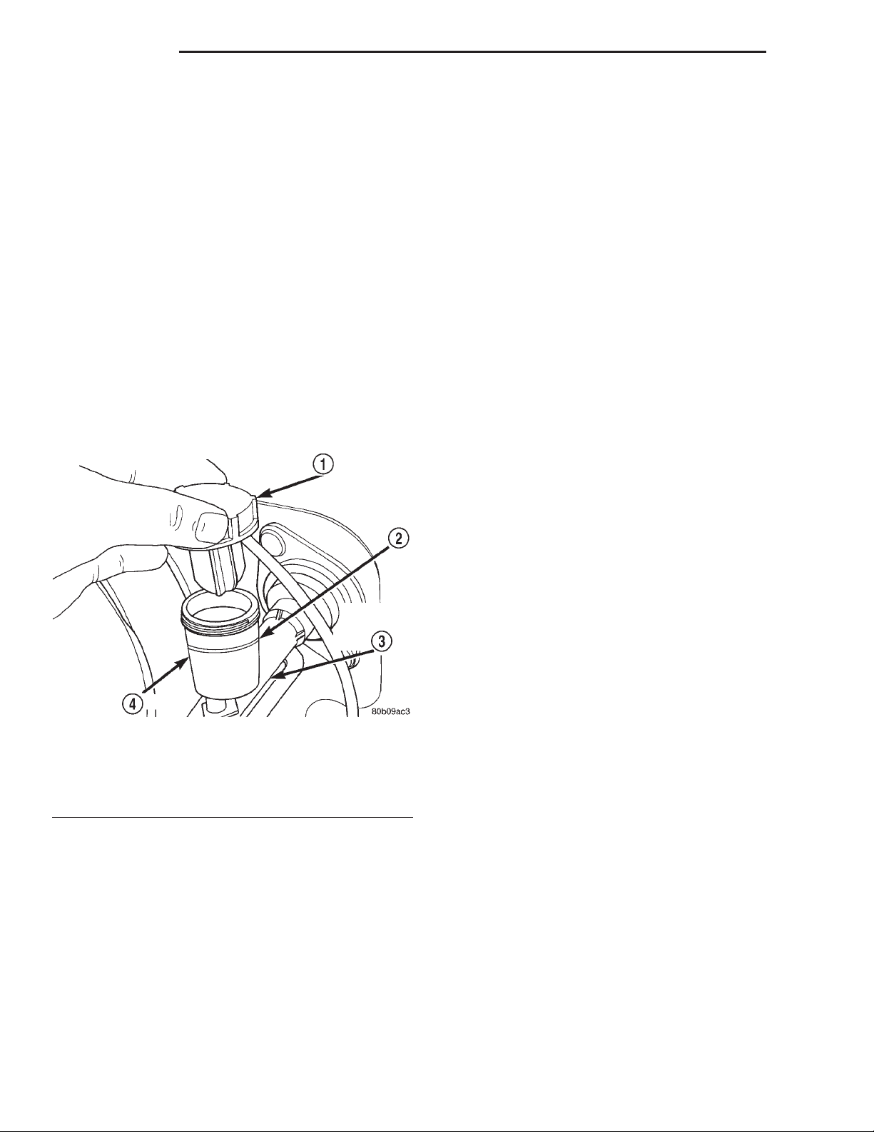
Clutch fluid level is checked at the master cylinder
reservoir (Fig. 9). An indicator ring is provided on the
outside rim of the reservoir.
Be sure to wipe the reservoir and cover clean
before removing the cover. This will avoid having dirt
or foreign material fall into the reservoir during a
fluid level check.
Fig. 9 Clutch Master Cylinder Reservoir And Cap
1 – CAP
2 – FILL LINE
3 – CLUTCH MASTER CYLINDER
4 – RESERVOIR
FLYWHEEL
Inspect the flywheel whenever the clutch disc,
cover and housing are removed for service. Check
condition of the flywheel face, hub, ring gear teeth,
and flywheel bolts.
Minor scratches, burrs, or glazing on the flywheel
face can be reduced with 180 grit emery cloth. However, the flywheel should be replaced if the disc contact surface is severely scored, heat checked, cracked,
or obviously worn.
Flywheel machining is not recommended. The flywheel surface is manufactured with a unique contour
that would be negated by machining. However,
cleanup of minor flywheel scoring can be performed
by hand with 180 grit emery, or with surface grinding equipment. Replace the flywheel if scoring is
deeper than 0.0762 mm (0.003 in.).
Heavy stock removal by grinding is not recom-
mended. Excessive stock removal can result in flywheel cracking or warpage after installation. It can
also weaken the flywheel and interfere with proper
clutch release.
Check flywheel runout if misalignment is suspected. Runout should not exceed 0.08 mm (0.003
in.). Measure runout at the outer edge of the flywheel face with a dial indicator. Mount the dial indicator on a stud installed in place of one of the clutch
housing attaching bolts.
Clean the crankshaft flange before mounting the
flywheel. Dirt and grease on the flange surface may
cock the flywheel causing excessive runout.
Check condition of the flywheel hub and attaching
bolts. Replace the flywheel if the hub exhibits cracks
in the area of the attaching bolt holes.
Install new attaching bolts whenever the flywheel
is replaced and use Mopart Lock N’ Seal, or Loctite
242 on the replacement bolt threads.
Recommended flywheel bolt torques are:
• 142 N·m (105 ft. lbs.) for 6-cylinder flywheels
• 95 N·m (70 ft. lbs.) for 4-cylinder flywheels
Inspect the teeth on the starter ring gear. If the
teeth are worn or damaged, the flywheel should
be replaced as an assembly. This is the recommended and preferred method of repair.
In cases where a new flywheel is not readily available, a replacement ring gear can be installed. However, the following precautions must be observed to
avoid damaging the flywheel and replacement gear.
(1) Mark position of the old gear for alignment reference on the flywheel. Use a scriber for this purpose.
(2) Wear protective goggles or approved safety
glasses. Also wear heat resistent gloves when handling a heated ring gear.
(3) Remove the old gear by cutting most of the way
through it (at one point) with an abrasive cut-off
wheel. Then complete removal with a cold chisel or
punch.
(4) The ring gear is a shrink fit on the flywheel.
This means the gear must be expanded by heating in
order to install it. The method of heating and
expanding the gear is extremely important.
Every surface of the gear must be heated at the same
time to produce uniform expansion. An oven or similar enclosed heating device must be used. Temperature required for uniform expansion is approximately
375° F.
Page 11
XJ CLUTCH 6 - 11
SERVICE PROCEDURES (Continued)
CAUTION: Do not use an oxy/acetylene torch to
remove the old gear, or to heat and expand a new
gear. The high temperature of the torch flame can
cause localized heating that will damage the flywheel. In addition, using the torch to heat a replacement gear will cause uneven heating and
expansion. The torch flame can also anneal the
gear teeth resulting in rapid wear and damage after
installation.
(5) The heated gear must be installed evenly to
avoid misalignment or distortion. A shop press and
suitable press plates should be used to install the
gear if at all possible.
(6) Be sure to wear eye and hand protection. Heat
resistent gloves and safety goggles are needed for
personal safety. Also use metal tongs, vise grips, or
similar tools to position the gear as necessary for
installation.
(7) Allow the flywheel and ring gear to cool down
before installation. Set the assembly on a workbench
and let it cool in normal shop air.
CAUTION: Do not use water, or compressed air to
cool the flywheel. The rapid cooling produced by
water or compressed air can distort, or crack the
gear and flywheel.
(a) Slide disc onto transmission input shaft
splines. Disc should slide freely on splines.
(b) Leave disc on shaft and check face runout
with dial indicator. Check runout at disc hub and
about 6 mm (1/4 in.) from outer edge of facing.
(c) Face runout should not exceed 0.5 mm (0.020
in.). Obtain another clutch disc if runout exceeds
this limit.
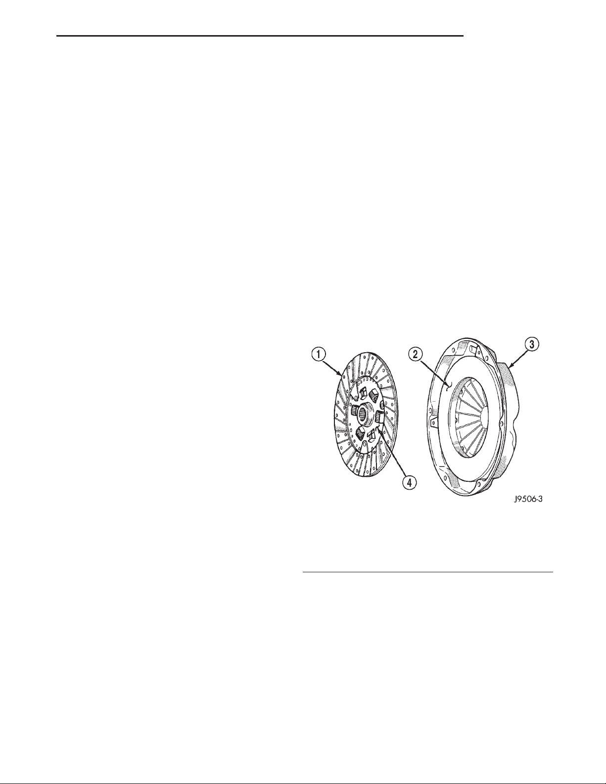
(4) Position clutch disc on flywheel. Be sure side of
disc marked flywheel side is positioned against flywheel (Fig. 10). If disc is not marked, be sure flat
side of disc hub is toward flywheel.
(5) Inspect condition of pressure plate surface of
clutch cover (Fig. 10). Replace cover if this surface is
worn, heat checked, cracked, or scored.
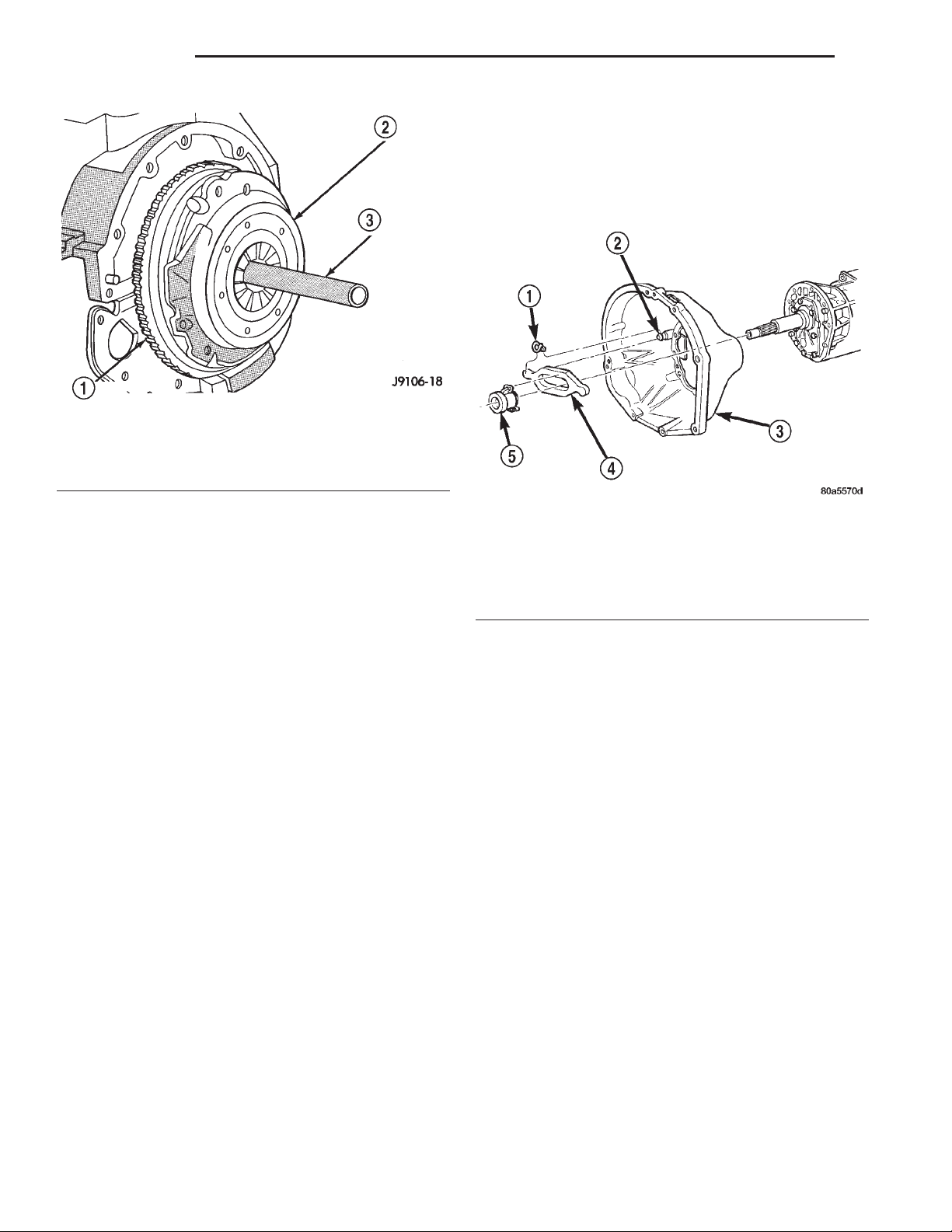
(6) Insert clutch alignment tool in clutch disc (Fig.
11).
(7) Insert alignment tool in pilot bearing and posi-
tion disc on flywheel. Be sure disc hub is positioned
correctly. Side of hub marked Flywheel Side should
face flywheel (Fig. 10). If disc is not marked, place
flat side of disc against flywheel.
REMOVAL AND INSTALLATION
CLUTCH COVER AND DISC
REMOVAL
(1) Remove transmission. Refer to procedures in
Group 21.
(2) If original clutch cover will be reinstalled, mark
position of cover on flywheel for assembly reference.
Use paint or a scriber for this purpose.
(3) If clutch cover is to be replaced, cover bolts can
be removed in any sequence. However, if original
cover will be reinstalled, loosen cover bolts evenly
and in rotation to relieve spring tension equally. This
is necessary to avoid warping cover.
(4) Remove cover bolts and remove cover and disc
(Fig. 10).
INSTALLATION
(1) Lightly scuff sand flywheel face with 180 grit
emery cloth. Then clean surface with a wax and
grease remover.
(2) Lubricate pilot bearing with Mopar high temperature bearing grease.
(3) Check runout and free operation of new clutch
disc as follows:
Fig. 10 Clutch Disc And Pressure Plate Inspection
1 – DISC
2 – INSPECT THIS SURFACE
3 – CLUTCH COVER
4 – “FLYWHEEL SIDE” STAMPED ON THIS SURFACE
(8) Position clutch cover over disc and on flywheel
(Fig. 11).
(9) Install clutch cover bolts finger tight.
(10) Tighten cover bolts evenly and in rotation a
few threads at a time. Cover bolts must be tight-
ened evenly and to specified torque to avoid
distorting cover. Tightening torques are 31 N·m
(23 ft. lbs.) on 2.5L engines and 50N·m (37ft. lbs.)
on 4.0 L engines.
(a) Start all 6 bolts by hand.
(b) Tighten 3 pilot hole bolts 3/4s of the way
(any sequence).
Page 12
6 - 12 CLUTCH XJ
REMOVAL AND INSTALLATION (Continued)
(2) Lubricate input shaft splines, bearing retainer
slide surface, fork pivot and release fork pivot surface
with Mopart high temperature grease.
(3) Install new release bearing. Be sure bearing is
properly secured to release fork.
(4) Install transmission.
Fig. 11 Typical Method Of Aligning Clutch Disc
1 – FLYWHEEL
2 – CLUTCH COVER AND DISC
3 – CLUTCH DISC ALIGNMENT TOOL
(c) Starting 180 degrees from the last pilot bolt,
tighten 3 large hole bolts 3/4s of the way (any
sequence).
(d) Tighten 3 pilot hole bolts all the way (any
sequence).
(e) Starting 180 degrees from last pilot bolt,
tighten 3 large bolts all the way (any sequence).
(11) Apply light coat of Mopart high temperature
bearing grease to clutch disc hub and splines of
transmission input shaft. Do not over lubricate
shaft splines. This will result in grease contamination of disc.
(12) Install transmission.
RELEASE BEARING
REMOVAL
(1) Remove transmission.
(2) Disconnect release bearing from release lever
and remove bearing (Fig. 12).
(3) Inspect bearing slide surface of transmission
front bearing retainer. Replace retainer if slide surface is scored, worn, or cracked.
(4) Inspect release fork and fork pivot. Be sure
pivot is secure and in good condition. Be sure fork is
not distorted or worn. Replace release fork retainer
spring if bent or damaged.
INSTALLATION
(1) Lubricate crankshaft pilot bearing with Mopart
high temperature bearing grease. Apply grease to
end of long shank, small diameter flat blade screwdriver. Then insert tool through clutch disc hub to
reach bearing.
Fig. 12 Release Bearing Attachment
1 – RETURN SPRING
2 – PIVOT BALL STUD
3 – CLUTCH HOUSING
4 – RELEASE FORK
5 – RELEASE BEARING
PILOT BEARING
REMOVAL
(1) Remove transmission. Refer to Group 21,
Transmission and Transfer Case, for proper procedures.
(2) Remove clutch cover and disc.
(3) Use a suitable blind hole puller to remove pilot
bearing.
INSTALLATION
(1) Clean bearing bore with solvent and wipe dry
with shop towel.
(2) Lubricate new pilot bearing with Mopart high
temperature grease.
(3) Position and start new bearing in bearing bore
by hand. Note that pilot bearing has seal at one end.
Install bearing so seal is facing outward toward
transmission.
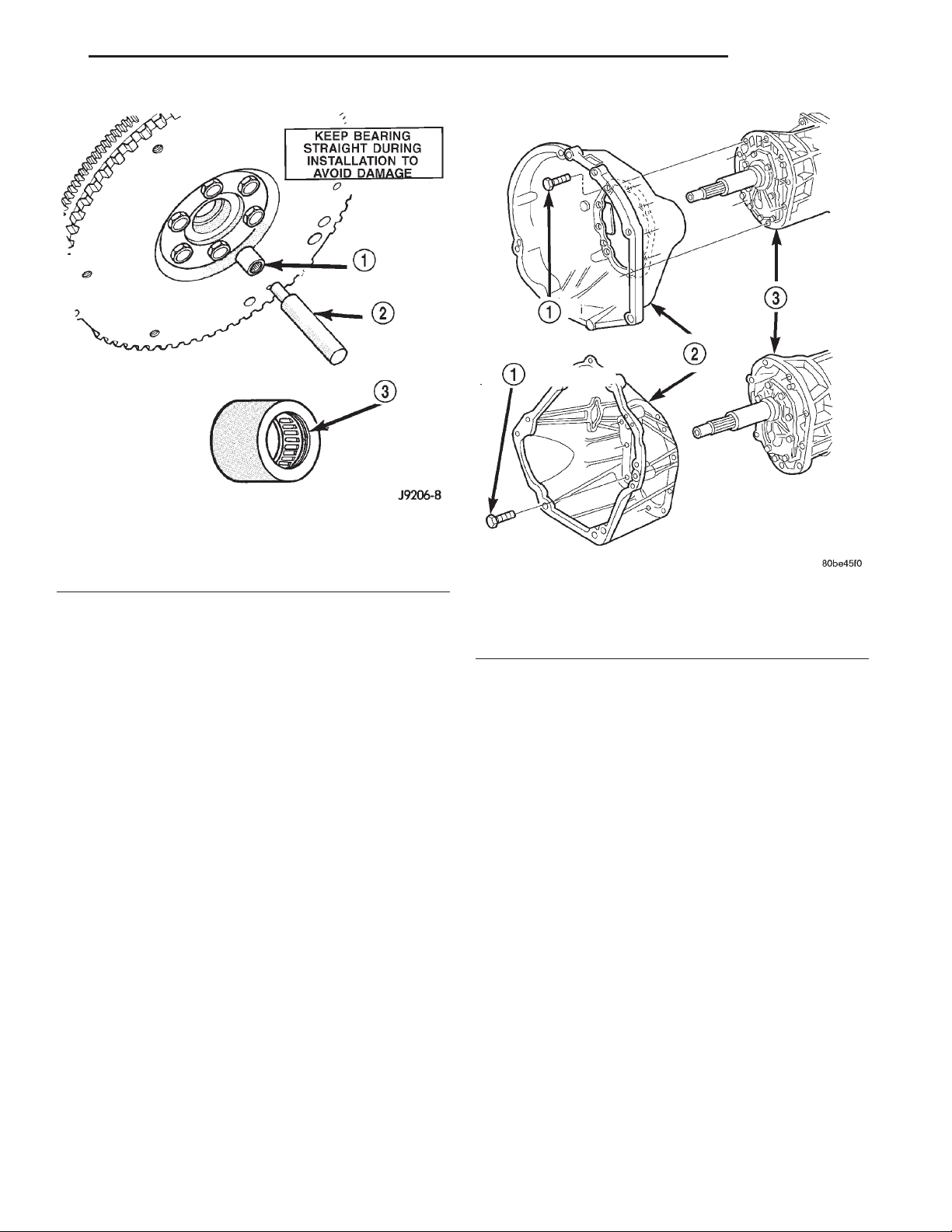
(4) Seat pilot bearing with clutch alignment tool
(Fig. 13). Keep bearing straight during installation.
Do not allow bearing to become cocked. Tap bearing
into place until flush with edge of bearing bore. Do
not recess bearing.
(5) Install transmission. Refer to Group 21, Transmission and Transfer Case, for proper procedures.
Page 13
XJ CLUTCH 6 - 13
REMOVAL AND INSTALLATION (Continued)
Fig. 13 Typical Method Of Installing Pilot Bearing
1 – PILOT BEARING
2 – ALIGNMENT TOOL
3 – BEARING SEAL MUST FACE TRANSMISSION
CLUTCH HOUSING
The clutch housing is removable and can be
replaced when the transmission is out of the vehicle.
The bolts attaching the housing to the transmission case are located inside the housing (Fig. 14).
Recommended tightening torque for the clutch housing-to-transmission bolts is 46 N·m (34 ft. lbs.).
NOTE: Be sure the transmission and housing mating surfaces are clean before installing an original,
or replacement clutch housing. Dirt/foreign material
trapped between the housing and transmission will
cause misalignment. If misalignment is severe
enough, the result will be clutch drag, incomplete
release and hard shifting.
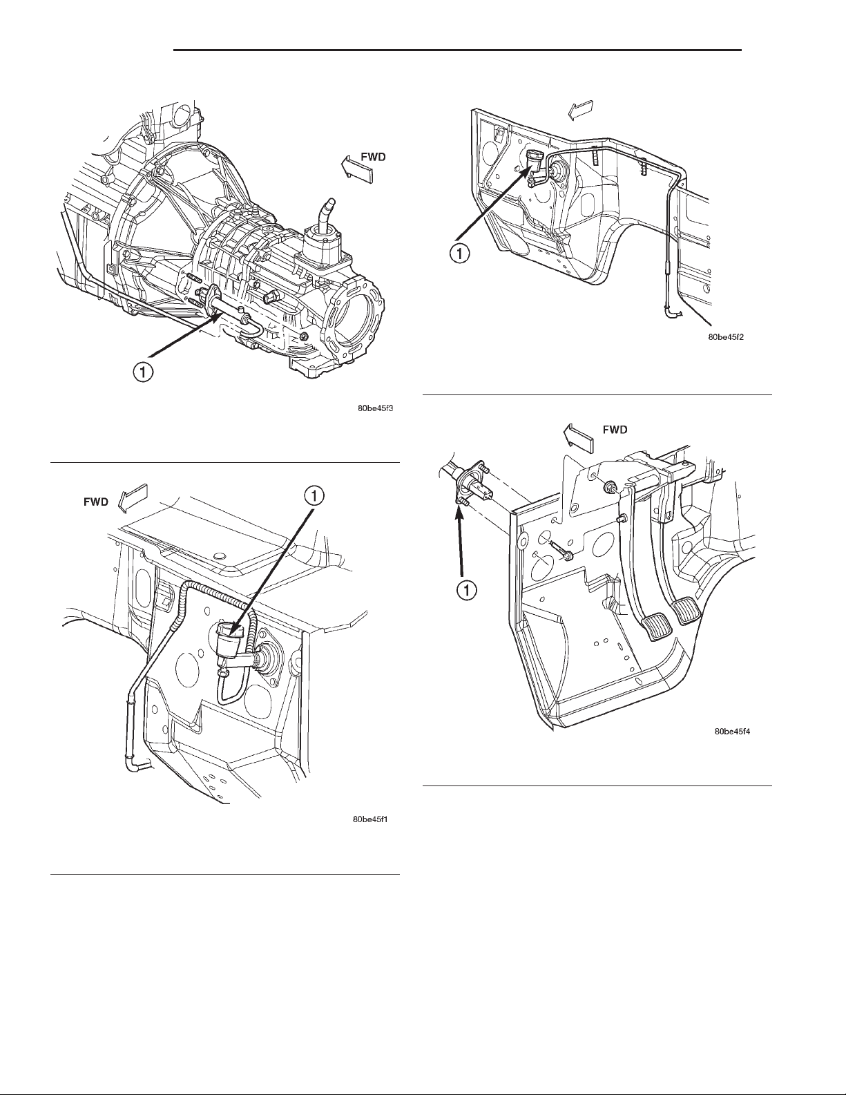
CLUTCH HYDRAULIC LINKAGE
The clutch master cylinder, slave cylinder and connecting line are serviced as an assembly only. The
linkage components cannot be overhauled or serviced
separately. The cylinders and connecting line are
sealed units. Also note that removal/installation procedures for right and left hand drive models are basically the same. Only master cylinder location is
different.
Fig. 14 Clutch Housing Attachment
1 – HOUSING-TO-TRANSMISSION BOLTS (46 N·m/34 ft. lbs.)
2 – CLUTCH HOUSING
3 – TRANSMISSION
REMOVAL
(1) Raise vehicle.
(2) Remove fasteners attaching slave cylinder to
clutch housing.
(3) Remove slave cylinder from clutch housing
(Fig. 15).
(4) Disengage clutch fluid line from body clips, if
applicable.
(5) Lower vehicle.
(6) Verify that cap on clutch master cylinder reservoir is tight. This is necessary to avoid spilling fluid
during removal.
(7) Remove clutch master cylinder attaching nuts
(Fig. 16) or (Fig. 17).
(8) Disengage captured bushing on clutch master
cylinder actuator from pivot pin on pedal arm (Fig.
18).
(9) Slide actuator off pivot pin.
(10) Disconnect clutch interlock safety switch
wires.
(11) Remove clutch hydraulic linkage through
engine compartment.
Page 14
6 - 14 CLUTCH XJ
REMOVAL AND INSTALLATION (Continued)
Fig. 17 Right Hand Drive Clutch Master Cylinder
1 – CLUTCH MASTER CYLINDER
Fig. 15 Slave Cylinder
1 – CLUTCH SLAVE CYLINDER
Fig. 16 Left Hand Drive Clutch Master Cylinder
1 – CLUTCH MASTER CYLINDER
INSTALLATION
(1) Be sure reservoir cover on clutch master cylin-
der is tight to avoid spills.
(2) Position clutch linkage components in vehicle.
Work connecting line and slave cylinder downward
past engine and adjacent to clutch housing (Fig. 16)
or (Fig. 17).
Fig. 18 Clutch Pedal Attachment
1 – CLUTCH MASTER CYLINDER
(3) Position clutch master cylinder on dash panel
(Fig. 16) or (Fig. 17).
(4) Attach clutch master cylinder actuator to pivot
pin on clutch pedal (Fig. 18).
(5) Install and tighten clutch master cylinder
attaching nuts to 38 N·m (28 ft. lbs.) torque.
(6) Raise vehicle.
(7) Insert slave cylinder push rod through clutch
housing opening and into release lever. Be sure cap
on end of rod is securely engaged in lever. Check this
before installing cylinder attaching nuts.
(8) Install and tighten slave cylinder attaching
nuts to 23 N·m (17 ft. lbs.) torque.
Page 15

XJ CLUTCH 6 - 15
REMOVAL AND INSTALLATION (Continued)
(9) Secure clutch fluid line in body and transmis-
sion clips.
(10) Lower vehicle.
(11) Connect clutch interlock safety switch wires.
SPECIFICATIONS
TORQUE
DESCRIPTION TORQUE
Bolts, clutch cover 2.5 L ....... 31N·m(23ft.lbs)
Bolts, clutch cover 4.0 L ....... 50N·m(37ft.lbs)
Bolt/Nut, clutch cyl. mount . . . 23 N·m (200 in. lbs)
Bolt, clutch housing M12 ...... 75N·m(55ft.lbs)
Bolt, clutch housing 3/8 ....... 37N·m(27ft.lbs)
Bolt, clutch housing 7/16 ...... 58N·m(43ft.lbs)
Bolt, clutch housing/trans. ..... 46N·m(34ft.lbs)
Bolt, dust shield M8 .......... 8N·m(72in.lbs)
Bolt, dust shield lower ........ 50N·m(37ft.lbs)
Bolt, X-member/frame ........ 41N·m(30ft.lbs)
Bolt, X-member/rear support . . . 45 N·m (33 ft. lbs.)
Bolts, flywheel 4.0 L ........ 142N·m(105 ft. lbs)
Bolts, flywheel 2.5 L ......... 95N·m(70ft.lbs)
Bolt, starter motor ........... 45N·m(33ft.lbs)
Bolts, U-joints ............. 19N·m(170 in. lbs.)
Page 16

 Loading...