

Page 1
XJ BRAKES 5 - 1
BRAKES
TABLE OF CONTENTS
page page
BASE BRAKE SYSTEM ...................... 1 ANTILOCK BRAKES ....................... 33
BASE BRAKE SYSTEM
TABLE OF CONTENTS
page page
DESCRIPTION AND OPERATION
BRAKE SYSTEM ..........................2
SERVICE WARNINGS & CAUTIONS ...........2
BRAKE PEDAL ...........................2
BRAKE LAMP SWITCH .....................2
RED BRAKE WARNING LAMP................3
POWER BRAKE BOOSTER ..................3
MASTER CYLINDER .......................3
COMBINATION VALVE......................3
FRONT DISC BRAKES......................4
REAR DRUM BRAKE.......................5
PARKING BRAKE..........................5
BRAKE HOSES AND LINES..................7
DIAGNOSIS AND TESTING
BASE BRAKE SYSTEM .....................7
BRAKE LAMP SWITCH .....................9
RED BRAKE WARNING LAMP................9
MASTER CYLINDER/POWER BOOSTER.......10
COMBINATION VALVE .....................11
DISC BRAKE ROTOR......................11
BRAKE DRUM ...........................11
BRAKE LINE AND HOSES ..................12
BRAKE FLUID CONTAMINATION.............12
SERVICE PROCEDURES
BRAKE FLUID LEVEL .....................12
MASTER CYLINDER BLEEDING .............12
BASE BRAKE BLEEDING...................13
DISC ROTOR MACHINING..................13
BRAKE DRUM MACHINING .................14
BRAKE TUBE FLARING....................14
REMOVAL AND INSTALLATION
BRAKE LAMP SWITCH ....................15
BRAKE PEDAL...........................15
COMBINATION VALVE.....................16
MASTER CYLINDER ......................16
POWER BRAKE BOOSTER .................17
FRONT DISC BRAKE CALIPER ..............18
FRONT DISC BRAKE SHOES ...............20
DISC BRAKE ROTOR .....................21
DRUM BRAKE SHOES.....................21
WHEEL CYLINDER .......................21
BRAKE SUPPORT PLATE ..................22
REAR PARKING BRAKE CABLES ............23
PARKING BRAKE LEVER...................23
DISASSEMBLY AND ASSEMBLY
MASTER CYLINDER RESERVOIR ............24
DISC BRAKE CALIPER ....................25
WHEEL CYLINDER .......................28
CLEANING AND INSPECTION
CALIPER ...............................28
REAR DRUM BRAKE......................29
WHEEL CYLINDER .......................29
ADJUSTMENTS
BRAKE LAMP SWITCH ....................30
REAR DRUM BRAKE......................30
PARKING BRAKE CABLE TENSIONER ........31
SPECIFICATIONS
BRAKE FLUID ...........................31
BRAKE COMPONENTS ....................32
TORQUE CHART.........................32
SPECIAL TOOLS
BASE BRAKES ..........................32
Page 2

5 - 2 BRAKES XJ
DESCRIPTION AND OPERATION
BRAKE SYSTEM
DESCRIPTION
Power assist front disc and rear drum brakes are
standard equipment. Disc brake components consist
of single piston calipers and ventilated rotors. Rear
drum brakes are dual shoe units with cast brake
drums.
The parking brake mechanism is lever and cable
operated. The cables are attached to levers on the
rear drum brake secondary shoes. The parking
brakes are operated by a hand lever.
A dual diaphragm vacuum power brake booster is
used for all applications. All models have an aluminum master cylinder with plastic reservoir.
All models are equipped with a combination valve.
The valve contains a pressure differential valve and
switch and a fixed rate rear proportioning valve.
Factory brake lining on all models consists of an
organic base material combined with metallic particles. The original equipment linings do not contain
asbestos.
SERVICE WARNINGS & CAUTIONS
DESCRIPTION
CAUTION: Never use gasoline, kerosene, alcohol,
motor oil, transmission fluid, or any fluid containing
mineral oil to clean the system components. These
fluids damage rubber cups and seals. Use only
fresh brake fluid or Mopar brake cleaner to clean or
flush brake system components. These are the only
cleaning materials recommended. If system contamination is suspected, check the fluid for dirt, discoloration, or separation into distinct layers. Also
check the reservoir cap seal for distortion. Drain
and flush the system with new brake fluid if contamination is suspected.
CAUTION: Use Mopar brake fluid, or an equivalent
quality fluid meeting SAE/DOT standards J1703 and
DOT 3. Brake fluid must be clean and free of contaminants. Use fresh fluid from sealed containers
only to ensure proper antilock component operation.
CAUTION: Use Mopar multi-mileage or high temperature grease to lubricate caliper slide surfaces,
drum brake pivot pins, and shoe contact points on
the backing plates. Use multi-mileage grease or GE
661 or Dow 111 silicone grease on caliper slide pins
to ensure proper operation.
WARNING: DUST AND DIRT ACCUMULATING ON
BRAKE PARTS DURING NORMAL USE MAY CONTAIN ASBESTOS FIBERS FROM AFTERMARKET
LININGS. BREATHING EXCESSIVE CONCENTRATIONS OF ASBESTOS FIBERS CAN CAUSE SERIOUS BODILY HARM. EXERCISE CARE WHEN
SERVICING BRAKE PARTS. DO NOT CLEAN
BRAKE PARTS WITH COMPRESSED AIR OR BY
DRY BRUSHING. USE A VACUUM CLEANER SPECIFICALLY DESIGNED FOR THE REMOVAL OF
ASBESTOS FIBERS FROM BRAKE COMPONENTS.
IF A SUITABLE VACUUM CLEANER IS NOT AVAILABLE, CLEANING SHOULD BE DONE WITH A
WATER DAMPENED CLOTH. DO NOT SAND, OR
GRIND BRAKE LINING UNLESS EQUIPMENT USED
IS DESIGNED TO CONTAIN THE DUST RESIDUE.
DISPOSE OF ALL RESIDUE CONTAINING ASBESTOS FIBERS IN SEALED BAGS OR CONTAINERS
TO MINIMIZE EXPOSURE TO YOURSELF AND OTHERS. FOLLOW PRACTICES PRESCRIBED BY THE
OCCUPATIONAL SAFETY AND HEALTH ADMINISTRATION AND THE ENVIRONMENTAL PROTECTION
AGENCY FOR THE HANDLING, PROCESSING, AND
DISPOSITION OF DUST OR DEBRIS THAT MAY
CONTAIN ASBESTOS FIBERS.
BRAKE PEDAL
DESCRIPTION
A suspended-type brake pedal is used, the pedal
pivots on a shaft mounted in the pedal support
bracket. The bracket is attached to the dash panel
and steering support bracket. The unit is serviced as
an assembly, except for the pedal pad.
OPERATION
The brake pedal is attached to the booster push
rod. When the pedal is depressed, the primary
booster push rod is depressed which move the booster
secondary rod. The booster secondary rod depress the
master cylinder piston.
BRAKE LAMP SWITCH
DESCRIPTION
The plunger type brake lamp switch is mounted on
a bracket attached to the brake pedal support. The
switch can be adjusted when necessary.
OPERATION
The brake lamp switch is used to for the brake
lamp, speed control and brake sensor circuits.
Page 3

XJ BRAKES 5 - 3
DESCRIPTION AND OPERATION (Continued)
RED BRAKE WARNING LAMP
DESCRIPTION
A red warning lamp is used for the service brake
portion of the hydraulic system. The lamp is located
in the instrument cluster.
OPERATION
The red warning light alerts the driver if a pressure differential exists between the front and rear
hydraulic systems or the parking brakes are applied.
The lamp is turned on momentarily when the ignition switch is turn to the on position. This is a self
test to verify the lamp is operational.
POWER BRAKE BOOSTER
DESCRIPTION
The booster assembly consists of a housing divided
into separate chambers by two internal diaphragms.
The outer edge of each diaphragm is attached to the
booster housing. The diaphragms are connected to
the booster primary push rod.
Two push rods are used in the booster. The primary push rod connects the booster to the brake
pedal. The secondary push rod connects the booster
to the master cylinder to stroke the cylinder pistons.
OPERATION
The atmospheric inlet valve is opened and closed
by the primary push rod. Booster vacuum supply is
through a hose attached to an intake manifold fitting
at one end and to the booster check valve at the
other. The vacuum check valve in the booster housing
is a one-way device that prevents vacuum leak back.
Power assist is generated by utilizing the pressure
differential between normal atmospheric pressure
and a vacuum. The vacuum needed for booster operation is taken directly from the engine intake manifold. The entry point for atmospheric pressure is
through a filter and inlet valve at the rear of the
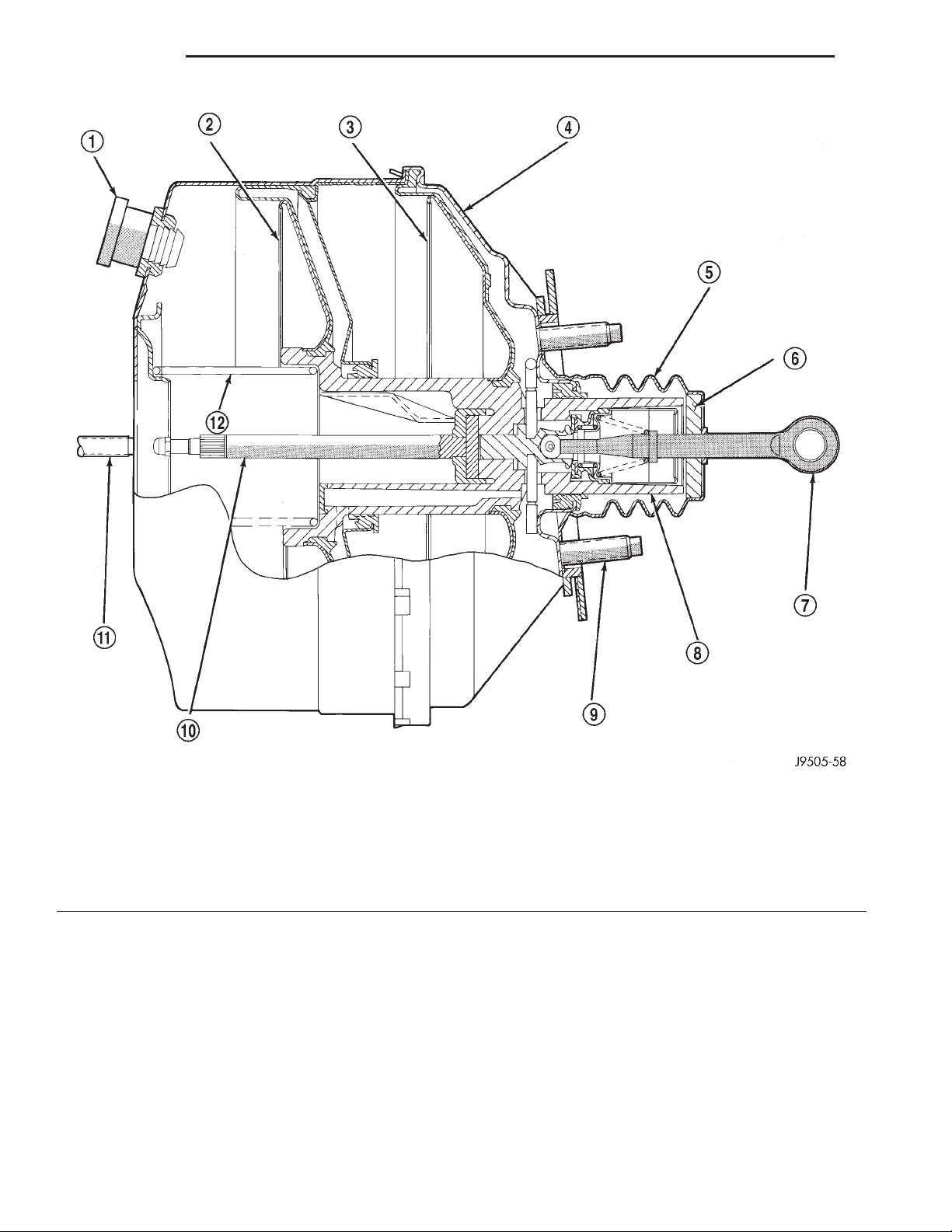
housing (Fig. 1).
The chamber areas forward of the booster diaphragms are exposed to vacuum from the intake
manifold. The chamber areas to the rear of the diaphragms, are exposed to normal atmospheric pressure of 101.3 kilopascals (14.7 pounds/square in.).
Brake pedal application causes the primary push
rod to open the atmospheric inlet valve. This exposes
the area behind the diaphragms to atmospheric pressure. The resulting pressure differential provides the
extra apply force for power assist.
The booster check valve, check valve grommet and
booster seals are serviceable.
MASTER CYLINDER
DESCRIPTION
The master cylinder has a removable nylon reservoir. The cylinder body is made of aluminum and
contains a primary and secondary piston assembly.
The cylinder body including the piston assemblies
are not serviceable. If diagnosis indicates an internal
problem with the cylinder body, it must be replaced
as an assembly. The reservoir and grommets are the
only replaceable parts on the master cylinder.
OPERATION
The master cylinder bore contains a primary and
secondary piston. The primary piston supplies
hydraulic pressure to the front brakes. The secondary
piston supplies hydraulic pressure to the rear brakes.
The master cylinder reservoir stores reserve brake
fluid for the hydraulic brake circuits.
COMBINATION VALVE
DESCRIPTION
The combination valve contains a pressure differential valve and switch and a rear brake proportioning valve. The valve is not repairable and must be
replaced as an assembly if diagnosis indicates this is
necessary.
OPERATION
PRESSURE DIFFERENTIAL VALVE
The pressure differential switch is connected to the
brake warning light. The switch is actuated by movement of the switch valve. The switch monitors fluid
pressure in the separate front/rear brake hydraulic
circuits.
A decrease or loss of fluid pressure in either
hydraulic circuit will cause the switch valve to shuttle to the low pressure side. Movement of the valve
pushes the switch plunger upward. This action closes
the switch internal contacts completing the electrical
circuit to the red warning light. The switch valve will
remain in an actuated position until repairs to the
brake system are made.
PROPORTIONING VALVE
The proportioning valve is used to balance frontrear brake action at high decelerations. The valve
allows normal fluid flow during moderate braking.
The valve only controls fluid flow during high decelerations brake stops.
Page 4
5 - 4 BRAKES XJ
DESCRIPTION AND OPERATION (Continued)
Fig. 1 Power Brake Booster–Typical
1 – VACUUM CHECK VALVE
2 – FRONT DIAPHRAGM
3 – REAR DIAPHRAGM
4 – HOUSING
5 – SEAL
6 – AIR FILTER
FRONT DISC BRAKES
DESCRIPTION
The calipers are a single piston type. The calipers
are free to slide laterally, this allows continuous compensation for lining wear.
OPERATION
When the brakes are applied fluid pressure is
exerted against the caliper piston. The fluid pressure
is exerted equally and in all directions. This means
7 – PRIMARY PUSH ROD (TO BRAKE PEDAL)
8 – ATMOSPHERIC INLET VALVE ASSEMBLY
9 – BOOSTER MOUNTING STUDS (4)
10 – SECONDARY PUSH ROD (TO MASTER CYLINDER)
11 – MASTER CYLINDER MOUNTING STUD (2)
12 – SPRING
pressure exerted against the caliper piston and
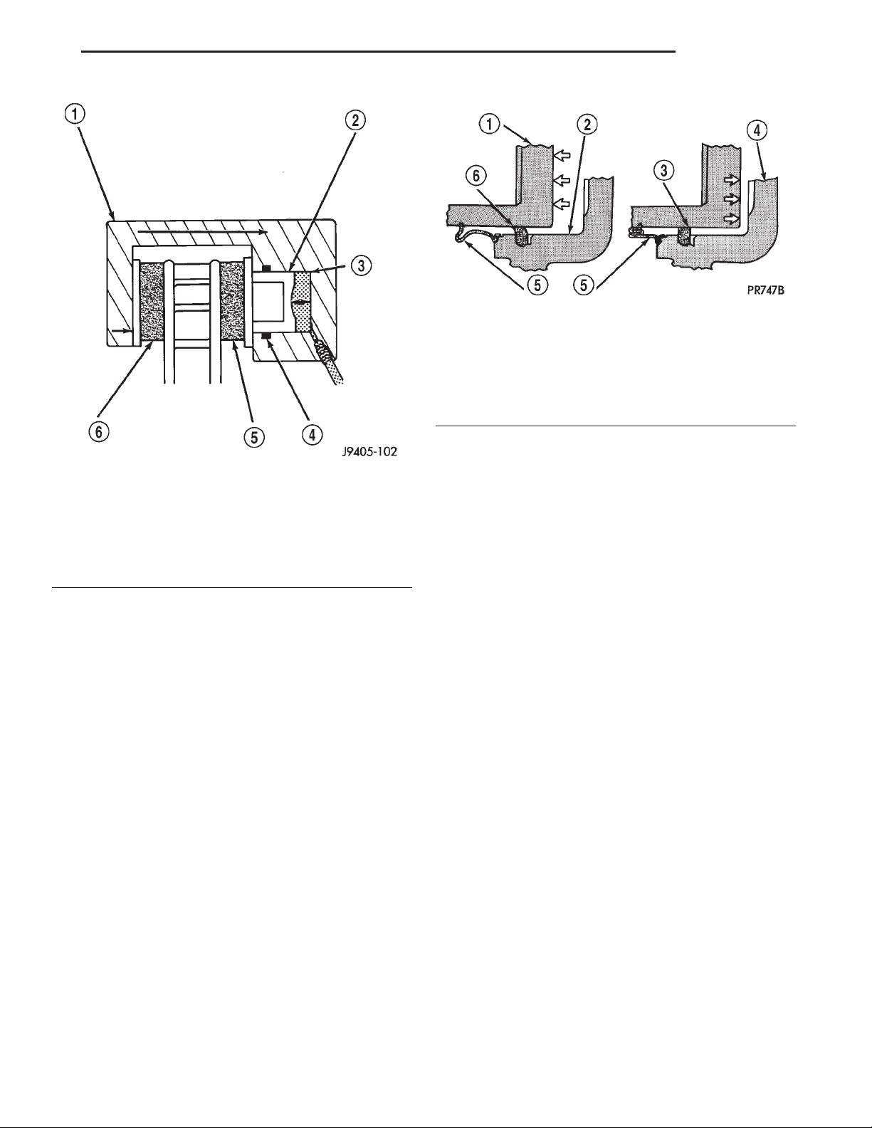
within the caliper bore will be equal (Fig. 2).
Fluid pressure applied to the piston is transmitted
directly to the inboard brake shoe. This forces the
shoe lining against the inner surface of the disc
brake rotor. At the same time, fluid pressure within
the piston bore forces the caliper to slide inward on
the mounting bolts. This action brings the outboard
brake shoe lining into contact with the outer surface
of the disc brake rotor.
Page 5
XJ BRAKES 5 - 5
DESCRIPTION AND OPERATION (Continued)
Fig. 3 Lining Wear Compensation By Piston Seal
1 – PISTON
2 – CYLINDER BORE
3 – PISTON SEAL BRAKE PRESSURE OFF
4 – CALIPER HOUSING
5 – DUST BOOT
6 – PISTON SEAL BRAKE PRESSURE ON
REAR DRUM BRAKE
Fig. 2 Brake Caliper Operation
1 – CALIPER
2 – PISTON
3 – PISTON BORE
4 – SEAL
5 – INBOARD SHOE
6 – OUTBOARD SHOE
In summary, fluid pressure acting simultaneously
on both piston and caliper, produces a strong clamping action. When sufficient force is applied, friction
will attempt to stop the rotors from turning and
bring the vehicle to a stop.
Application and release of the brake pedal generates only a very slight movement of the caliper and
piston. Upon release of the pedal, the caliper and piston return to a rest position. The brake shoes do not
retract an appreciable distance from the rotor. In
fact, clearance is usually at, or close to zero. The reasons for this are to keep road debris from getting
between the rotor and lining and in wiping the rotor
surface clear each revolution.
The caliper piston seal controls the amount of piston extension needed to compensate for normal lining
wear.
During brake application, the seal is deflected outward by fluid pressure and piston movement (Fig. 3).
When the brakes (and fluid pressure) are released,
the seal relaxes and retracts the piston.
The amount of piston retraction is determined by
the amount of seal deflection. Generally the amount
is just enough to maintain contact between the piston and inboard brake shoe.
DESCRIPTION
The rear brakes use a leading shoe (primary) and
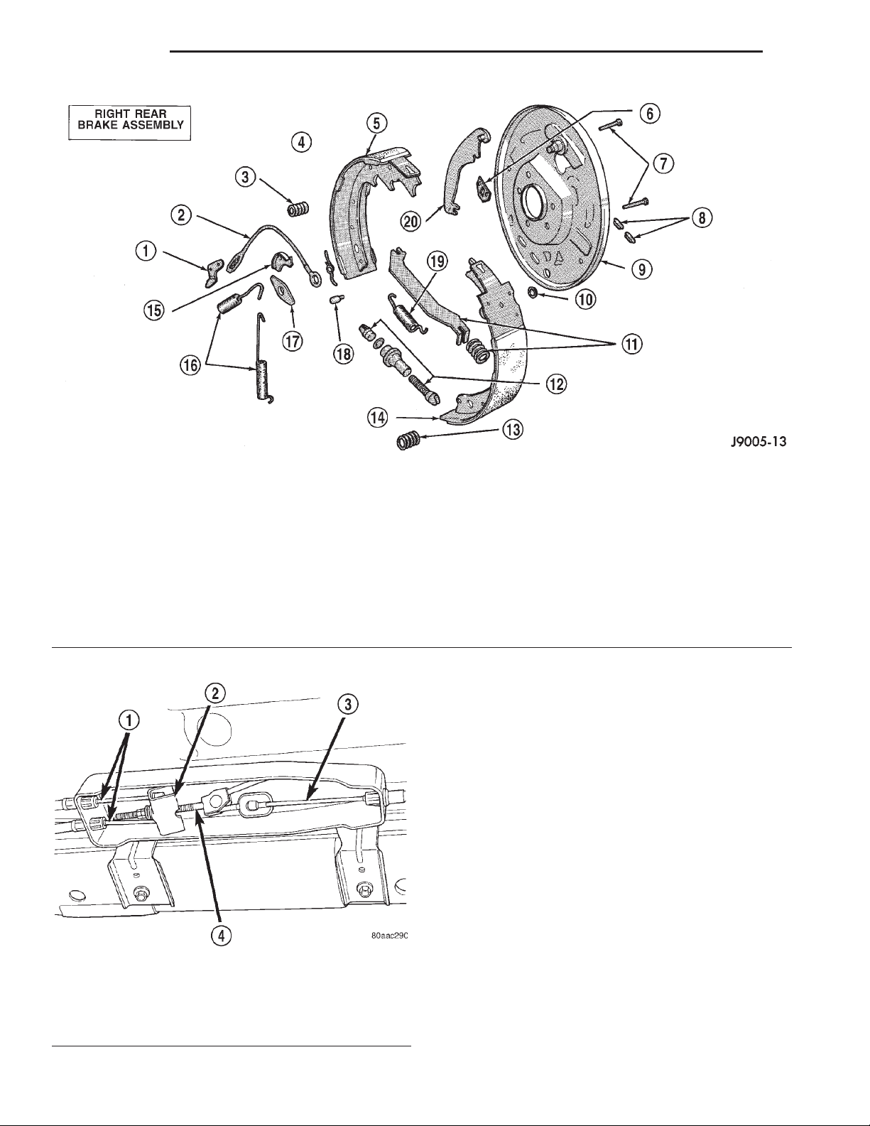
trailing shoe (secondary) design (Fig. 4).
OPERATION
When the brake pedal is depressed hydraulic pressure pushes the rear brake wheel cylinder pistons
outward. The wheel cylinder push rods then push the
brake shoes outward against the brake drum. When
the brake pedal is released return springs attached
to the brake shoes pull the shoes back to there original position.
PARKING BRAKE
DESCRIPTION
The parking bake is a hand lever and cable operated system used to apply the rear brakes.
OPERATION
A hand operated lever in the passenger compartment is the main application device. The front cable
is connected between the hand lever and the tensioner. The tensioner rod is attached to the equalizer
which is the connecting point for the rear cables (Fig.
5).
The rear cables are connected to the actuating
lever on each secondary brake shoe. The levers are
attached to the brake shoes by a pin either pressed
into, or welded to the lever. A clip is used to secure
the pin in the brake shoe. The pin allows each lever
to pivot independently of the brake shoe.
To apply the parking brakes, the hand lever is
pulled upward. This pulls the rear brake shoe actu-
Page 6
5 - 6 BRAKES XJ
DESCRIPTION AND OPERATION (Continued)
1 – ADJUSTER LEVER
2 – ADJUSTER CABLE
3 – HOLDDOWN SPRING AND RETAINERS
4 – ADJUSTER LEVER SPRING
5 – TRAILING SHOE
6 – CYLINDER-TO-SUPPORT SEAL
7 – HOLDDOWN PINS
8 – ACCESS PLUGS
9 – SUPPORT PLATE
10 – CABLE HOLE PLUG
Fig. 5 Parking Brake Components
1 – REAR CABLES
2 – EQUALIZER
3 – FRONT CABLE
4 – TENSIONER ROD
Fig. 4 Brake Components
11 – PARK BRAKE STRUTAND SPRING
12 – ADJUSTER SCREW ASSEMBLY
13 – HOLDDOWN SPRING AND RETAINERS
14 – LEADING SHOE
15 – CABLE GUIDE
16 – SHOE RETURN SPRINGS
17 – SHOE GUIDE PLATE
18 – PIN
19 – SHOE SPRING
20 – PARK BRAKE LEVER
ating levers forward, by means tensioner and cables.
As the actuating lever is pulled forward, the parking
brake strut (which is connected to both shoes), exerts
a linear force against the primary brake shoe. This
action presses the primary shoe into contact with the
drum. Once the primary shoe contacts the drum,
force is exerted through the strut. This force is transferred through the strut to the secondary brake shoe
causing it to pivot into the drum as well.
A gear type ratcheting mechanism is used to hold
the lever in an applied position. Parking brake
release is accomplished by the hand lever release
button.
A parking brake switch is mounted on the parking
brake lever and is actuated by movement of the
lever. The switch, which is in circuit with the red
warning light in the dash, will illuminate the warning light whenever the parking brakes are applied.
Parking brake adjustment is controlled by a cable
tensioner mechanism. The cable tensioner, once
adjusted at the factory, should not need further
adjustment under normal circumstances. Adjustment
Page 7

XJ BRAKES 5 - 7
DESCRIPTION AND OPERATION (Continued)
may be required if a new tensioner, or cables are
installed, or disconnected.
BRAKE HOSES AND LINES
DESCRIPTION
Flexible rubber hose is used at both front brakes
and at the rear axle junction block. Double walled
steel tubing is used to connect the master cylinder to
the major hydraulic braking components and then to
the flexible rubber hoses. Double inverted style and
ISO style flares are used on the brake lines.
DIAGNOSIS AND TESTING
BASE BRAKE SYSTEM
Base brake components consist of the brake shoes,
calipers, wheel cylinders, brake drums, rotors, brake
lines, master cylinder, booster, and parking brake
components.
Brake diagnosis involves determining if the problem is related to a mechanical, hydraulic, or vacuum
operated component.
The first diagnosis step is the preliminary check.
PRELIMINARY BRAKE CHECK
(1) Check condition of tires and wheels. Damaged
wheels and worn, damaged, or underinflated tires
can cause pull, shudder, vibration, and a condition
similar to grab.
(2) If complaint was based on noise when braking,
check suspension components. Jounce front and rear
of vehicle and listen for noise that might be caused
by loose, worn or damaged suspension or steering
components.
(3) Inspect brake fluid level and condition. Note
that the brake reservoir fluid level will decrease in
proportion to normal lining wear. Also note that
brake fluid tends to darken over time. This is
normal and should not be mistaken for contamination.
(a) If fluid level is abnormally low, look for evidence of leaks at calipers, wheel cylinders, brake
lines, and master cylinder.
(b) If fluid appears contaminated, drain out a
sample to examine. System will have to be flushed
if fluid is separated into layers, or contains a substance other than brake fluid. The system seals
and cups will also have to be replaced after flushing. Use clean brake fluid to flush the system.
(4) Check parking brake operation. Verify free
movement and full release of cables and pedal. Also
note if vehicle was being operated with parking
brake partially applied.
(5) Check brake pedal operation. Verify that pedal
does not bind and has adequate free play. If pedal
lacks free play, check pedal and power booster for
being loose or for bind condition. Do not road test
until condition is corrected.
(6) Check booster vacuum check valve and hose.
(7) If components checked appear OK, road test
the vehicle.
ROAD TESTING
(1) If complaint involved low brake pedal, pump
pedal and note if it comes back up to normal height.
(2) Check brake pedal response with transmission
in Neutral and engine running. Pedal should remain
firm under constant foot pressure.
(3) During road test, make normal and firm brake
stops in 25-40 mph range. Note faulty brake operation such as low pedal, hard pedal, fade, pedal pulsation, pull, grab, drag, noise, etc.
(4) Attempt to stop the vehicle with the parking
brake only and note grab, drag, noise, etc.
PEDAL FALLS AWAY
A brake pedal that falls away under steady foot
pressure is generally the result of a system leak. The
leak point could be at a brake line, fitting, hose, or
caliper/wheel cylinder. If leakage is severe, fluid will
be evident at or around the leaking component.
Internal leakage (seal by-pass) in the master cylinder caused by worn or damaged piston cups, may
also be the problem cause.
An internal leak in the ABS or RWAL system may
also be the problem with no physical evidence.
LOW PEDAL
If a low pedal is experienced, pump the pedal several times. If the pedal comes back up worn linings,
rotors, drums, or rear brakes out of adjustment are
the most likely causes. The proper course of action is
to inspect and replace all worn component and make
the proper adjustments.
SPONGY PEDAL
A spongy pedal is most often caused by air in the
system. However, thin brake drums or substandard
brake lines and hoses can also cause a spongy pedal.
The proper course of action is to bleed the system,
and replace thin drums and substandard quality
brake hoses if suspected.
HARD PEDAL OR HIGH PEDAL EFFORT
A hard pedal or high pedal effort may be due to
lining that is water soaked, contaminated, glazed, or
badly worn. The power booster or check valve could
also be faulty.
Page 8

5 - 8 BRAKES XJ
DIAGNOSIS AND TESTING (Continued)
PEDAL PULSATION
Pedal pulsation is caused by components that are
loose, or beyond tolerance limits.
The primary cause of pulsation are disc brake
rotors with excessive lateral runout or thickness variation, or out of round brake drums. Other causes are
loose wheel bearings or calipers and worn, damaged
tires.
NOTE: Some pedal pulsation may be felt during
ABS activation.
BRAKE DRAG
Brake drag occurs when the lining is in constant
contact with the rotor or drum. Drag can occur at one
wheel, all wheels, fronts only, or rears only.
Drag is a product of incomplete brake shoe release.
Drag can be minor or severe enough to overheat the
linings, rotors and drums.
Minor drag will usually cause slight surface charring of the lining. It can also generate hard spots in
rotors and drums from the overheat-cool down process. In most cases, the rotors, drums, wheels and
tires are quite warm to the touch after the vehicle is
stopped.
Severe drag can char the brake lining all the way
through. It can also distort and score rotors and
drums to the point of replacement. The wheels, tires
and brake components will be extremely hot. In
severe cases, the lining may generate smoke as it
chars from overheating.
Common causes of brake drag are:
• Seized or improperly adjusted parking brake
cables.
• Loose/worn wheel bearing.
• Seized caliper or wheel cylinder piston.
• Caliper binding on corroded bushings or rusted
slide surfaces.
• Loose caliper mounting.
• Drum brake shoes binding on worn/damaged
support plates.
• Mis-assembled components.
• Long booster output rod.
If brake drag occurs at all wheels, the problem
may be related to a blocked master cylinder return
port, or faulty power booster (binds-does not release).
BRAKE FADE
Brake fade is usually a product of overheating
caused by brake drag. However, brake overheating
and resulting fade can also be caused by riding the
brake pedal, making repeated high deceleration stops
in a short time span, or constant braking on steep
mountain roads. Refer to the Brake Drag information
in this section for causes.
BRAKE PULL
Front brake pull condition could result from:
• Contaminated lining in one caliper
• Seized caliper piston
• Binding caliper
• Loose caliper
• Rusty caliper slide surfaces
• Improper brake shoes
• Damaged rotor
A worn, damaged wheel bearing or suspension
component are further causes of pull. A damaged
front tire (bruised, ply separation) can also cause
pull.
A common and frequently misdiagnosed pull condition is where direction of pull changes after a few
stops. The cause is a combination of brake drag followed by fade at one of the brake units.
As the dragging brake overheats, efficiency is so
reduced that fade occurs. Since the opposite brake
unit is still functioning normally, its braking effect is
magnified. This causes pull to switch direction in
favor of the normally functioning brake unit.
An additional point when diagnosing a change in
pull condition concerns brake cool down. Remember
that pull will return to the original direction, if the
dragging brake unit is allowed to cool down (and is
not seriously damaged).
REAR BRAKE GRAB OR PULL
Rear grab or pull is usually caused by improperly
adjusted or seized parking brake cables, contaminated lining, bent or binding shoes and support
plates, or improperly assembled components. This is
particularly true when only one rear wheel is
involved. However, when both rear wheels are
affected, the master cylinder or proportioning valve
could be at fault.
BRAKES DO NOT HOLD AFTER DRIVING THROUGH DEEP
WATER PUDDLES
This condition is generally caused by water soaked
lining. If the lining is only wet, it can be dried by
driving with the brakes very lightly applied for a
mile or two. However, if the lining is both soaked and
dirt contaminated, cleaning and/or replacement will
be necessary.
BRAKE LINING CONTAMINATION
Brake lining contamination is mostly a product of
leaking calipers or wheel cylinders, worn seals, driving through deep water puddles, or lining that has
become covered with grease and grit during repair.
Contaminated lining should be replaced to avoid further brake problems.
Page 9
XJ BRAKES 5 - 9
DIAGNOSIS AND TESTING (Continued)
WHEEL AND TIRE PROBLEMS
Some conditions attributed to brake components
may actually be caused by a wheel or tire problem.
A damaged wheel can cause shudder, vibration and
pull. A worn or damaged tire can also cause pull.
Severely worn tires with very little tread left can
produce a grab-like condition as the tire loses and
recovers traction. Flat-spotted tires can cause vibration and generate shudder during brake operation. A
tire with internal damage such as a severe bruise,
cut, or ply separation can cause pull and vibration.
BRAKE NOISES
Some brake noise is common with rear drum
brakes and on some disc brakes during the first few
stops after a vehicle has been parked overnight or
stored. This is primarily due to the formation of trace
corrosion (light rust) on metal surfaces. This light
corrosion is typically cleared from the metal surfaces
after a few brake applications causing the noise to
subside.
BRAKE SQUEAK/SQUEAL
Brake squeak or squeal may be due to linings that
are wet or contaminated with brake fluid, grease, or
oil. Glazed linings and rotors with hard spots can
also contribute to squeak. Dirt and foreign material
embedded in the brake lining will also cause squeak/
squeal.
A very loud squeak or squeal is frequently a sign of
severely worn brake lining. If the lining has worn
through to the brake shoes in spots, metal-to-metal
contact occurs. If the condition is allowed to continue,
rotors and drums can become so scored that replacement is necessary.
BRAKE CHATTER
Brake chatter is usually caused by loose or worn
components, or glazed/burnt lining. Rotors with hard
spots can also contribute to chatter. Additional causes
of chatter are out-of-tolerance rotors, brake lining not
securely attached to the shoes, loose wheel bearings
and contaminated brake lining.
THUMP/CLUNK NOISE
Thumping or clunk noises during braking are frequently not caused by brake components. In many
cases, such noises are caused by loose or damaged
steering, suspension, or engine components. However,
calipers that bind on the slide surfaces can generate
a thump or clunk noise. In addition, worn out,
improperly adjusted, or improperly assembled rear
brake shoes can also produce a thump noise.
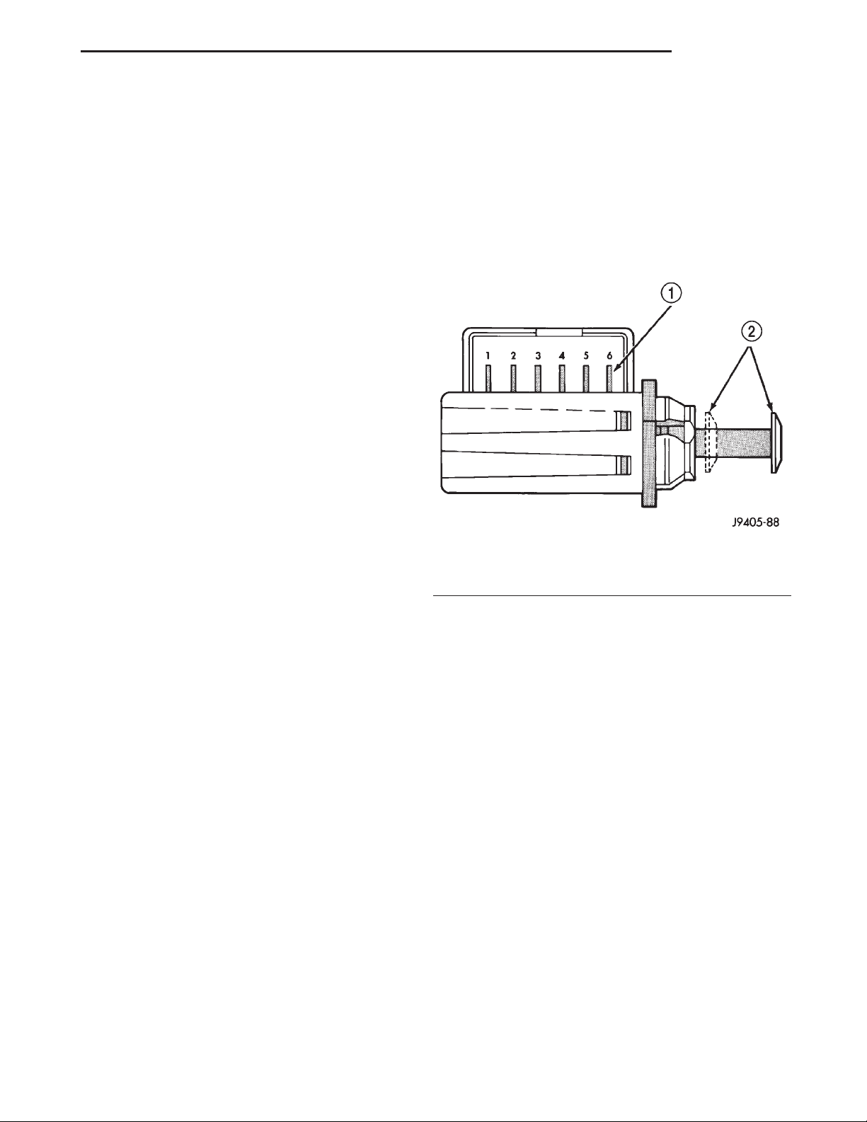
BRAKE LAMP SWITCH
The brake lamp switch operation can be tested
with an ohmmeter. The ohmmeter is used to check
continuity between the pin terminals (Fig. 6).
SWITCH CIRCUIT IDENTIFICATION
• Terminals 1 and 2: brake sensor circuit
• Terminals 3 and 4: speed control circuit if
equipped
• Terminals 5 and 6: brake lamp circuit
Fig. 6 Brake Lamp Switch Terminal Identification
1 – TERMINAL PINS
2 – PLUNGER TEST POSITIONS
SWITCH CONTINUITY TEST
NOTE: Disconnect switch harness before testing
switch continuity.
With the switch plunger retracted, attach test
leads to terminal pins 1 and 2. Replace switch if
meter indicates no continuity.
With the switch plunger retracted, attach test
leads to terminal pins 3 and 4. Replace switch if
meter indicates no continuity.
With the switch plunger extended, attach test
leads to terminal pins 5 and 6. Replace switch if
meter indicates no continuity.
RED BRAKE WARNING LAMP
The red brake warning lamp will illuminate under
the following conditions:
• Self test at start-up.
• Parking brakes are applied.
• Leak in front/rear brake hydraulic circuit.
If the red light remains on after start-up, first verify that the parking brakes are fully released. Then
check pedal action and fluid level. If the lamp on and
the brake pedal is low this indicates the pressure dif-
Page 10
5 - 10 BRAKES XJ
DIAGNOSIS AND TESTING (Continued)
ferential switch and valve have been actuated due to
a leak in the hydraulic system.
On models with ABS brakes, the amber warning
lamp only illuminates during the self test and when
an ABS malfunction has occurred. The ABS lamp
operates independently of the red warning lamp.
For additional information refer to Group 8W.
MASTER CYLINDER/POWER BOOSTER
(1) Start engine and check booster vacuum hose
connections. A hissing noise indicates vacuum leak.
Correct any vacuum leak before proceeding.
(2) Stop engine and shift transmission into Neutral.
(3) Pump brake pedal until all vacuum reserve in
booster is depleted.
(4) Press and hold brake pedal under light foot
pressure. The pedal should hold firm, if the pedal
falls away master cylinder is faulty (internal leakage).
(5) Start engine and note pedal action. It should
fall away slightly under light foot pressure then hold
firm. If no pedal action is discernible, power booster,
vacuum supply, or vacuum check valve is faulty. Proceed to the POWER BOOSTER VACUUM TEST.
(6) If the POWER BOOSTER VACUUM TEST
passes, rebuild booster vacuum reserve as follows:
Release brake pedal. Increase engine speed to 1500
rpm, close the throttle and immediately turn off ignition to stop engine.
(7) Wait a minimum of 90 seconds and try brake
action again. Booster should provide two or more vacuum assisted pedal applications. If vacuum assist is
not provided, booster is faulty.
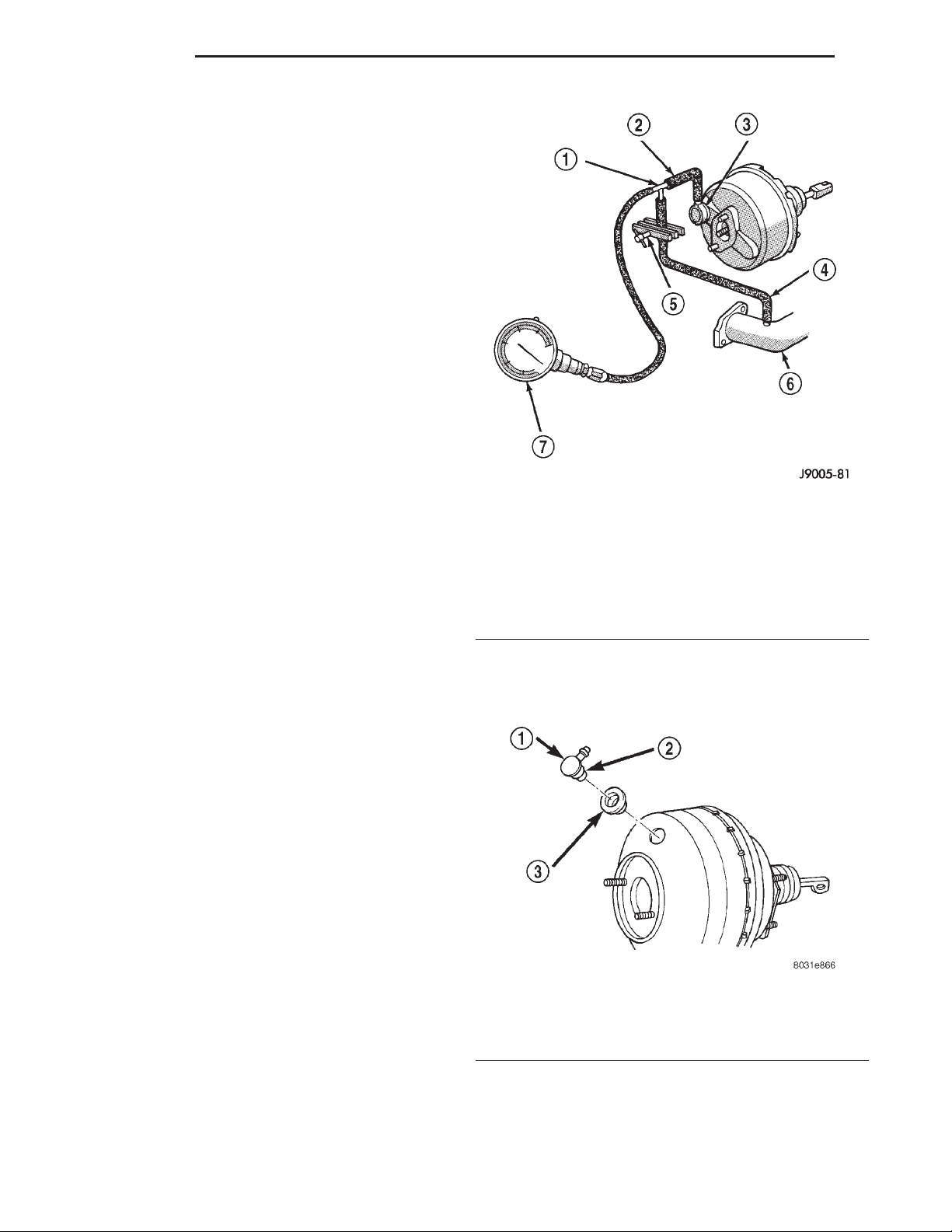
Fig. 7 Typical Booster Vacuum Test Connections
1 – TEE FITTING
2 – SHORT CONNECTING HOSE
3 – CHECK VALVE
4 – CHECK VALVE HOSE
5 – CLAMP TOOL
6 – INTAKE MANIFOLD
7 – VACUUM GAUGE
(5) Vacuum should hold steady. If gauge on pump
indicates vacuum loss, check valve is faulty and
should be replaced.
POWER BOOSTER VACUUM TEST
(1) Connect vacuum gauge to booster check valve
with short length of hose and T-fitting (Fig. 7).
(2) Start and run engine at curb idle speed for one
minute.
(3) Observe the vacuum supply. If vacuum supply
is not adequate, repair vacuum supply.
(4) Clamp hose shut between vacuum source and
check valve.
(5) Stop engine and observe vacuum gauge.
(6) If vacuum drops more than one inch HG (33
millibars) within 15 seconds, booster diaphragm or
check valve is faulty.
POWER BOOSTER CHECK VALVE TEST
(1) Disconnect vacuum hose from check valve.
(2) Remove check valve and valve seal from
booster.
(3) Use a hand operated vacuum pump for test.
(4) Apply 15-20 inches vacuum at large end of
check valve (Fig. 8).
Fig. 8 Vacuum Check Valve And Seal
1 – BOOSTER CHECK VALVE
2 – APPLY TEST VACUUM HERE
3 – VALVE SEAL
Page 11
XJ BRAKES 5 - 11
DIAGNOSIS AND TESTING (Continued)
COMBINATION VALVE
PRESSURE DIFFERENTIAL SWITCH
(1) Have helper sit in drivers seat to apply brake
pedal and observe red brake warning light.
(2) Raise vehicle on hoist.
(3) Connect bleed hose to a rear wheel cylinder
and immerse hose end in container partially filled
with brake fluid.
(4) Have helper press and hold brake pedal to floor
and observe warning light.
(a) If warning light illuminates, switch is operat-
ing correctly.
(b) If light fails to illuminate, check circuit fuse,
bulb, and wiring. The parking brake switch can be
used to aid in identifying whether or not the brake
light bulb and fuse is functional. Repair or replace
parts as necessary and test differential pressure
switch operation again.
(5) If warning light still does not illuminate,
switch is faulty. Replace combination valve assembly,
bleed brake system and verify proper switch and
valve operation.
REAR PROPORTIONING VALVE
The valve controls fluid flow. If fluid enters the
valve and does not exit the valve the combination
valve must be replaced.
DISC BRAKE ROTOR
The rotor braking surfaces should not be refinished
unless necessary.
Light surface rust and scale can be removed with a
lathe equipped with dual sanding discs. The rotor
surfaces can be restored by machining in a disc brake
lathe if surface scoring and wear are light.
Replace the rotor under the following conditions:
• severely scored
• tapered
• hard spots
• cracked
• below minimum thickness
ROTOR MINIMUM THICKNESS
Measure rotor thickness at the center of the brake
shoe contact surface. Replace the rotor if worn below
minimum thickness, or if machining would reduce
thickness below the allowable minimum.
Rotor minimum thickness is usually specified on
the rotor hub. The specification is either stamped or
cast into the hub surface.
ROTOR RUNOUT
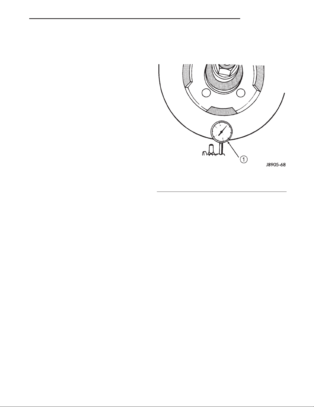
Check rotor lateral runout with dial indicator
C-3339 (Fig. 9). Excessive lateral runout will cause
brake pedal pulsation and rapid, uneven wear of the
brake shoes. Position the dial indicator plunger
approximately 25.4 mm (1 in.) inward from the rotor
edge. Maximum allowable rotor runout is 0.102 mm
(0.004 in.).
Fig. 9 Checking Rotor Runout And Thickness
Variation
1 – DIAL INDICATOR
ROTOR THICKNESS VARIATION
Variations in rotor thickness will cause pedal pul-
sation, noise and shudder.
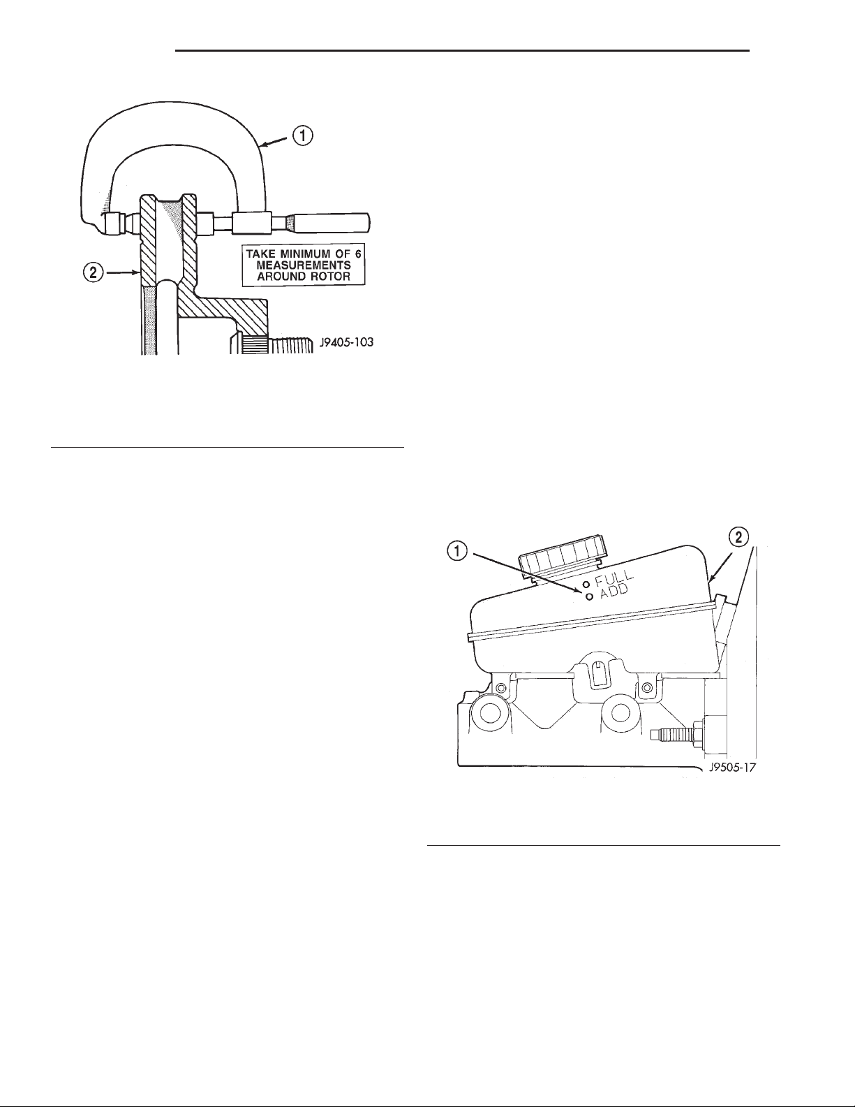
Measure rotor thickness at 6 to 12 points around
the rotor face (Fig. 10).
Position the micrometer approximately 25.4 mm (1
in.) from the rotor outer circumference for each measurement.
Thickness should not vary by more than 0.013 mm
(0.0005 in.) from point-to-point on the rotor. Machine
or replace the rotor if necessary.
BRAKE DRUM
The maximum allowable diameter of the drum
braking surface is indicated on the drum outer edge.
Generally, a drum can be machined to a maximum of
1.52 mm (0.060 in.) oversize. Always replace the
drum if machining would cause drum diameter to
exceed the size limit indicated on the drum.
BRAKE DRUM RUNOUT
Measure drum diameter and runout with an accurate gauge. The most accurate method of measurement involves mounting the drum in a brake lathe
and checking variation and runout with a dial indicator.
Variations in drum diameter should not exceed
0.076 mm (0.003 in.). Drum runout should not exceed
0.20 mm (0.008 in.) out of round. Machine the drum
if runout or variation exceed these values. Replace
Page 12
5 - 12 BRAKES XJ
DIAGNOSIS AND TESTING (Continued)
BRAKE FLUID CONTAMINATION
Indications of fluid contamination are swollen or
deteriorated rubber parts.
Swollen rubber parts indicate the presence of
petroleum in the brake fluid.
To test for contamination, put a small amount of
drained brake fluid in clear glass jar. If fluid separates into layers, there is mineral oil or other fluid
contamination of the brake fluid.
If brake fluid is contaminated, drain and thoroughly flush system. Replace master cylinder, proportioning valve, caliper seals, wheel cylinder seals,
Antilock Brakes hydraulic unit and all hydraulic
fluid hoses.
SERVICE PROCEDURES
Fig. 10 Measuring Rotor Thickness
1 – MICROMETER
2 – ROTOR
the drum if machining causes the drum to exceed the
maximum allowable diameter.
BRAKE LINE AND HOSES
Flexible rubber hose is used at both front brakes
and at the rear axle junction block. Inspect the hoses
whenever the brake system is serviced, at every
engine oil change, or whenever the vehicle is in for
service.
Inspect the hoses for surface cracking, scuffing, or
worn spots. Replace any brake hose immediately if
the fabric casing of the hose is exposed due to cracks
or abrasions.
Also check brake hose installation. Faulty installation can result in kinked, twisted hoses, or contact
with the wheels and tires or other chassis components. All of these conditions can lead to scuffing,
cracking and eventual failure.
The steel brake lines should be inspected periodically for evidence of corrosion, twists, kinks, leaks, or
other damage. Heavily corroded lines will eventually
rust through causing leaks. In any case, corroded or
damaged brake lines should be replaced.
Factory replacement brake lines and hoses are recommended to ensure quality, correct length and superior fatigue life. Care should be taken to make sure
that brake line and hose mating surfaces are clean
and free from nicks and burrs. Also remember that
right and left brake hoses are not interchangeable.
Use new copper seal washers at all caliper connections. Be sure brake line connections are properly
made (not cross threaded) and tightened to recommended torque.
BRAKE FLUID LEVEL
Always clean the master cylinder reservoir and cap
before adding fluid. This will prevent dirt from falling in the reservoir and contaminating the brake
fluid.
The reservoir has a ADD and a FULL mark on the
side (Fig. 11) fill to the FULL mark.
Fig. 11 Master Cylinder Fluid Level
1 – FLUID LEVEL MARKS
2 – RESERVOIR
MASTER CYLINDER BLEEDING
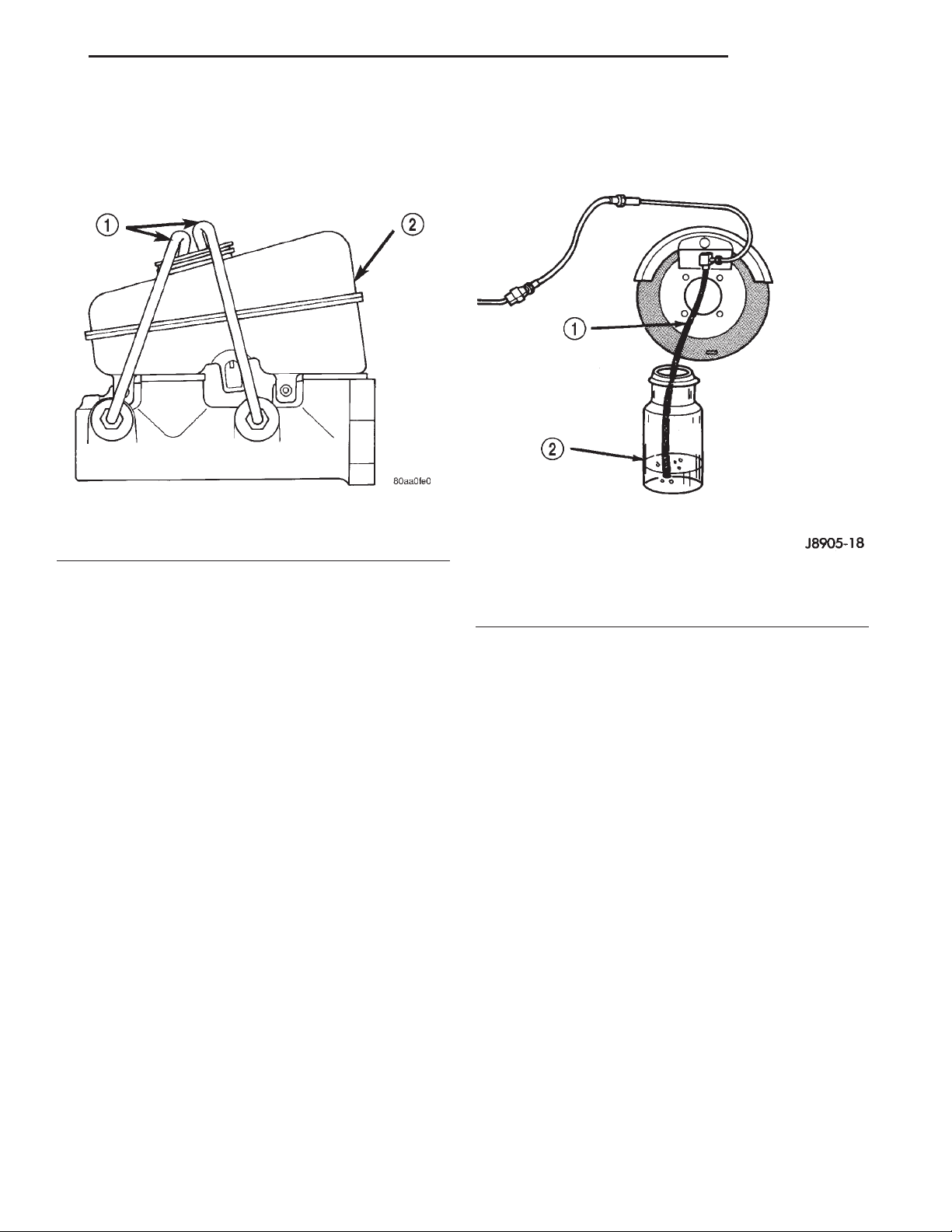
A new master cylinder should be bled before installation on the vehicle. Required bleeding tools include
bleed tubes and a wood dowel to stroke the pistons.
Bleed tubes can be fabricated from brake line.
BLEEDING PROCEDURE
(1) Mount master cylinder in vise.
(2) Attach bleed tubes to cylinder outlet ports.
Then position each tube end into reservoir (Fig. 12).
Page 13
XJ BRAKES 5 - 13
SERVICE PROCEDURES (Continued)
(3) Fill reservoir with fresh brake fluid.
(4) Press cylinder pistons inward with wood dowel.
Then release pistons and allow them to return under
spring pressure. Continue bleeding operations until
air bubbles are no longer visible in fluid.
Fig. 12 Master Cylinder Bleeding–Typical
1 – BLEEDING TUBES
2 – RESERVOIR
(3) Attach one end of bleed hose to bleed screw
and insert opposite end in glass container partially
filled with brake fluid (Fig. 13). Be sure end of bleed
hose is immersed in fluid.
BASE BRAKE BLEEDING
Use Mopar brake fluid, or an equivalent quality
fluid meeting SAE J1703-F and DOT 3 standards
only. Use fresh, clean fluid from a sealed container at
all times.
Do not pump the brake pedal at any time while
bleeding. Air in the system will be compressed into
small bubbles that are distributed throughout the
hydraulic system. This will make additional bleeding
operations necessary.
Do not allow the master cylinder to run out of fluid
during bleed operations. An empty cylinder will allow
additional air to be drawn into the system. Check the
cylinder fluid level frequently and add fluid as
needed.
Bleed only one brake component at a time in the
following sequence:
• Master Cylinder
• Combination Valve
• Right Rear Wheel
• Left Rear Wheel
• Right Front Wheel
• Left Front Wheel
MANUAL BLEEDING
(1) Remove reservoir filler caps and fill reservoir.
(2) If calipers, or wheel cylinders were overhauled,
open all caliper and wheel cylinder bleed screws.
Then close each bleed screw as fluid starts to drip
from it. Top off master cylinder reservoir once more
before proceeding.
Fig. 13 Bleed Hose Setup
1 – BLEED HOSE
2 – FLUID CONTAINER PARTIALLY FILLED WITH FLUID
(4) Open up bleeder, then have a helper press
down the brake pedal. Once the pedal is down close
the bleeder. Repeat bleeding until fluid stream is
clear and free of bubbles. Then move to the next
wheel.
PRESSURE BLEEDING
Follow the manufacturers instructions carefully
when using pressure equipment. Do not exceed the
tank manufacturers pressure recommendations. Generally, a tank pressure of 15-20 psi is sufficient for
bleeding.
Fill the bleeder tank with recommended fluid and
purge air from the tank lines before bleeding.
Do not pressure bleed without a proper master cylinder adapter. The wrong adapter can lead to leakage, or drawing air back into the system. Use
adapter provided with the equipment or Adapter
6921.
DISC ROTOR MACHINING
The disc brake rotor can be machined if scored or
worn. The lathe must machine both sides of the rotor
simultaneously with dual cutter heads. The rotor
mounting surface must be clean before placing on the
lathe. Equipment capable of machining only one side
at a time may produce a tapered rotor. A hub
Page 14
5 - 14 BRAKES XJ
SERVICE PROCEDURES (Continued)
mounted on-vehicle lathe is recommended. This type
of lathe trues the rotor to the vehicles hub/bearing.
CAUTION: Brake rotors that do not meet minimum
thickness specifications before or after machining
must be replaced.
BRAKE DRUM MACHINING
The brake drums can be machined on a drum lathe
when necessary. Initial machining cuts should be limited to 0.12 - 0.20 mm (0.005 - 0.008 in.) at a time as
heavier feed rates can produce taper and surface
variation. Final finish cuts of 0.025 to 0.038 mm
(0.001 to 0.0015 in.) are recommended and will generally provide the best surface finish.
Be sure the drum is securely mounted in the lathe
before machining operations. A damper strap should
always be used around the drum to reduce vibration
and avoid chatter marks.
The maximum allowable diameter of the drum
braking surface is stamped or cast into the drum
outer edge.
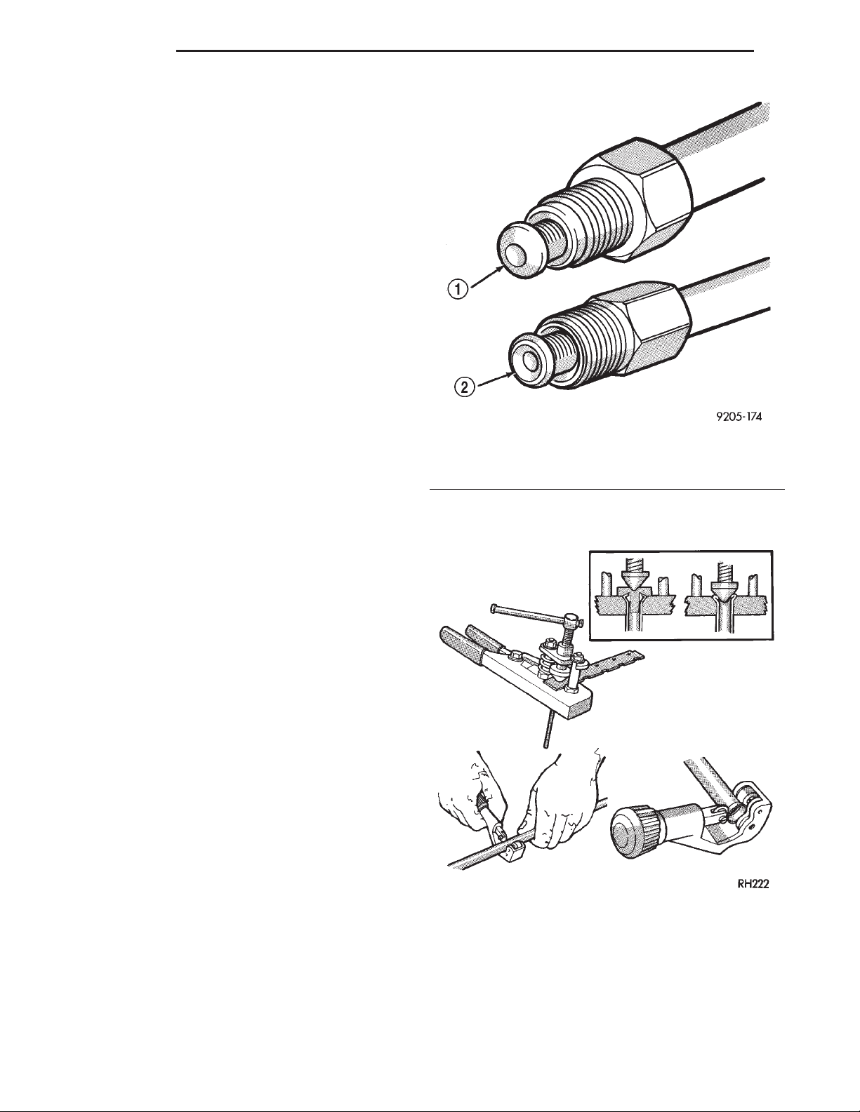
1 – ISO-STYLE FLARE
2 – DOUBLE INVERTED-STYLE FLARE
Fig. 14 Inverted Flare And ISO Flare
CAUTION: Replace the drum if machining will
cause the drum to exceed the maximum allowable
diameter.
BRAKE TUBE FLARING
A preformed metal brake tube is recommended and
preferred for all repairs. However, double-wall steel
tube can be used for emergency repair when factory
replacement parts are not readily available.
Special bending tools are needed to avoid kinking
or twisting of metal brake tubes. Special flaring tools
are needed to make a double inverted flare or ISO
flare (Fig. 14).
DOUBLE INVERTED FLARING
(1) Cut off damaged tube with Tubing Cutter.
(2) Ream cut edges of tubing to ensure proper
flare.
(3) Install replacement tube nut on the tube.
(4) Insert tube in flaring tool.
(5) Place gauge form over the end of the tube.
(6) Push tubing through flaring tool jaws until
tube contacts recessed notch in gauge that matches
tube diameter.
(7) Tighten the tool bar on the tube
(8) Insert plug on gauge in the tube. Then swing
compression disc over gauge and center tapered flaring screw in recess of compression disc (Fig. 15).
(9) Tighten tool handle until plug gauge is
squarely seated on jaws of flaring tool. This will start
the inverted flare.
(10) Remove the plug gauge and complete the
inverted flare.
Fig. 15 Inverted Flare Tools
ISO FLARING
To make a ISO flare use Snap-Ont Flaring Tool
TFM-428 or equivalent.
(1) Cut off damaged tube with Tubing Cutter.
(2) Remove any burrs from the inside of the tube.
(3) Install tube nut on the tube.
Page 15
XJ BRAKES 5 - 15
SERVICE PROCEDURES (Continued)
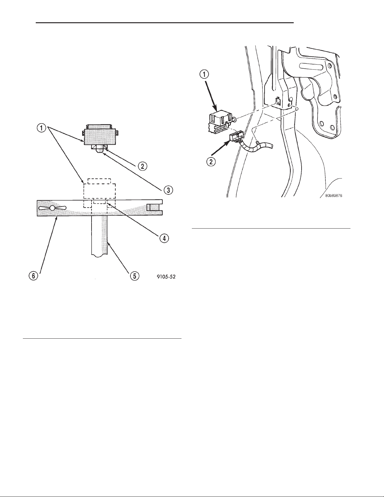
(4) Position the tube in the flaring tool flush with
the top of the tool bar (Fig. 16). Then tighten the tool
bar on the tube.
(5) Install the correct size adaptor on the flaring
tool yoke screw.
(6) Lubricate the adaptor.
(7) Align the adaptor and yoke screw over the tube
(Fig. 16).
(8) Turn the yoke screw in until the adaptor is
squarely seated on the tool bar.
Fig. 16 ISO Flaring
1 – ADAPTER
2 – LUBRICATE HERE
3 – PILOT
4 – FLUSH WITH BAR
5 – TUBING
6 – BAR ASSEMBLY
REMOVAL AND INSTALLATION
BRAKE LAMP SWITCH
REMOVAL
(1) Remove steering column cover and lower trim
panel for switch access (if necessary).
(2) Press brake pedal downward to fully applied
position.
(3) Rotate switch approximately 30° in counterclockwise direction to unlock switch retainer. Then
pull switch rearward and out of bracket.
(4) Disconnect switch harness and remove switch
from vehicle (Fig. 17).
Fig. 17 Brake Lamp Switch
1 – SWITCH
2 – HARNESS CONNECTOR
INSTALLATION
(1) Pull switch plunger all the way out to fully
extended position.
(2) Connect harness wires to switch.
(3) Press and hold brake pedal in applied position.
(4) Install switch as follows: Align tab on switch
with notch in switch bracket. Then insert switch in
bracket and turn it clockwise about 30° to lock it in
place.
(5) Release brake pedal. Then pull pedal lightly
rearward. Pedal will set plunger to correct position
as pedal pushes plunger into switch body. Switch will
make ratcheting sound as it self adjusts.
CAUTION: Booster damage may occur if the pedal
pull exceeds 20 lbs..
BRAKE PEDAL
REMOVAL
(1) Remove knee blocker under the steering column.
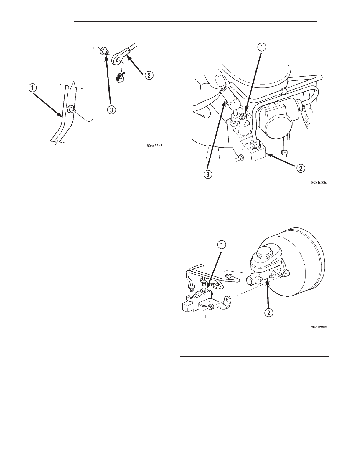
(2) Remove retainer clip securing booster push rod
to pedal (Fig. 18).
(3) Remove brake lamp switch.
(4) Remove nuts securing the booster to the pedal
support bracket and nuts to the column bracket.
(5) Remove pedal and support bracket as an
assembly from the vehicle.
Page 16
5 - 16 BRAKES XJ
REMOVAL AND INSTALLATION (Continued)
Fig. 18 Booster Push Rod
1 – BRAKE PEDAL
2 – BOOSTER ROD
3 – BUSHING
INSTALLATION
(1) Install pedal and support bracket as an assem-
bly into the vehicle.
(2) Install nuts securing the booster to the pedal
support bracket and nuts to the column bracket.
(3) Tighten nuts to 39 N·m (29 ft. lbs.).
(4) Lubricate the brake pedal pin and bushings
with Mopar multi-mileage grease.
(5) Install booster push rod on pedal pin and
install new retainer clip.
(6) Install knee blocker.
COMBINATION VALVE
NOTE: The combination valve is not repairable. The
valve is serviced as an assembly only.
REMOVAL
(1) Remove air cleaner cover and hose for access to
valve.
(2) Unsnap connector lock tabs and disconnect differential pressure switch wire at combination valve
(Fig. 19). Do not pull switch wire to disconnect.
(3) Disconnect brake lines at combination valve
(Fig. 20).
(4) Remove mounting nut and remove valve.
Fig. 19 Differential Pressure Switch
1 – SWITCH TERMINAL
2 – COMBINATION VALVE
3 – WIRE HARNESS CONNECTOR
Fig. 20 Combination Valve
1 – COMBINATION VALVE
2 – MASTER CYLINDER
(4) Connect wire to pressure differential switch.
(5) Bleed base brakes.
INSTALLATION
(1) Install valve and tighten mounting nut to 17
N·m (155 in. lbs.).
(2) Connect brake lines to replacement valve. Start
line fittings by hand to avoid cross threading.
(3) Tighten brake line fittings to 14 N·m (124 in.
lbs.).
MASTER CYLINDER
REMOVAL
(1) Remove brake lines at master cylinder and
combination valve (Fig. 20).
(2) Disconnect differential pressure switch wire
from the combination valve.
Page 17
XJ BRAKES 5 - 17
REMOVAL AND INSTALLATION (Continued)
(3) Remove mounting nuts from the combination
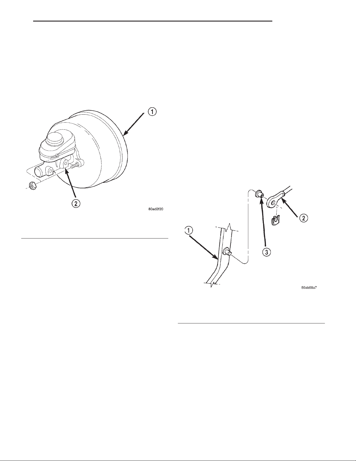
valve bracket and remove the valve (Fig. 20).
(4) Remove mounting nuts from the master cylinder (Fig. 21).
(5) Remove master cylinder.
(6) Remove cylinder cover and drain fluid.
(7) If master cylinder reservoir requires service,
refer to reservoir replacement procedure in this section.
POWER BRAKE BOOSTER
REMOVAL
(1) On RHD vehicles remove the coolant reserve/
overflow tank. Refer to Group 7 Cooling System.
(2) Disconnect brake lines at master cylinder.
(3) Disconnect wire at combination valve differen-
tial pressure switch.
(4) Remove nut mounting combination valve
bracket to booster studs and remove valve.
(5) Remove nuts mounting master cylinder to
booster studs and remove cylinder.
(6) Disconnect vacuum hose from booster check
valve.
(7) Remove knee blocker under the steering col-
umn.
(8) Remove retaining clip that secures booster
push rod to brake pedal (Fig. 22).
(9) Remove nuts attaching booster to passenger
compartment side of dash panel (Fig. 23).
Fig. 21 Master Cylinder
1 – BOOSTER
2 – MASTER CYLINDER
INSTALLATION
NOTE: If master cylinder is replaced, bleed cylinder
before installation.
(1) Remove protective sleeve from primary piston
shank on new master cylinder.
(2) Clean cylinder mounting surface of brake
booster.
(3) Install master cylinder onto brake booster
studs.
(4) Install mounting nuts and tighten to 17 N·m
(155 in. lbs.).
(5) Install combination valve and install mounting
nuts.
(6) Connect brake lines to master cylinder and
combination valve and tighten to 14 N·m (124 in.
lbs.).
(7) Connect differential pressure switch wire to the
combination valve.
(8) On RHD vehicles install the coolant reserve/
overflow tank. Refer to Group 7 Cooling System.
(9) Fill and bleed base brake system.
Fig. 22 Booster Push Rod
1 – BRAKE PEDAL
2 – BOOSTER ROD
3 – BUSHING
(10) In engine compartment, slide booster studs
out of dash panel, tilt booster upward, and remove
booster from engine compartment.
(11) Remove dash seal from booster.
INSTALLATION
(1) Install dash seal on booster.
(2) Align and position booster on dash panel.
(3) In passenger compartment, install booster
mounting nuts. Tighten nuts just enough to hold
booster in place.
(4) Slide booster push rod onto the brake pedal.
Then secure push rod to pedal pin with retaining
clip.
Page 18
5 - 18 BRAKES XJ
REMOVAL AND INSTALLATION (Continued)
(3) Drain small amount of fluid from master cylinder brake reservoir with suction gun.
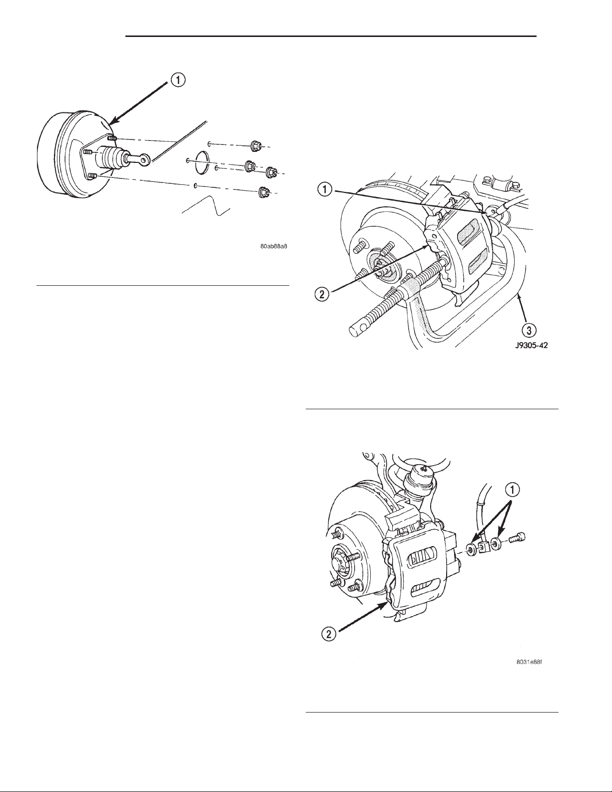
(4) Bottom caliper piston in bore with C-clamp.
Position clamp screw on outboard brake shoe and
clamp frame on rear of caliper (Fig. 24). Do not
allow clamp screw to bear directly on outboard
shoe retainer spring. Use wood or metal spacer
between shoe and clamp screw.
Fig. 23 Booster Mounting
1 – BOOSTER
NOTE: Lubricate the pedal pin and bushing with
Mopar multi-mileage grease before installation.
(5) Tighten booster mounting nuts to 39 N·m (29
ft. lbs.).
(6) Install the knee blocker.
(7) If original master cylinder is being installed,
check condition of seal at rear of master cylinder.
Replace seal if cut, or torn.
(8) Clean cylinder mounting surface of brake
booster. Use shop towel wetted with brake cleaner for
this purpose. Dirt, grease, or similar materials will
prevent proper cylinder seating and could result in
vacuum leak.
(9) Align and install master cylinder on booster
studs. Install mounting nuts and tighten to 17.5 N·m
(155 in. lbs.).
(10) Connect vacuum hose to booster check valve.
(11) Connect and secure brake lines to combination
valve and master cylinder. Start all brake line fittings by hand to avoid cross threading.
(12) Install combination valve on booster studs.
Tighten bracket mounting nuts to 17.5 N·m (155 in.
lbs.).
(13) Connect wire to combination valve switch.
(14) On RHD vehicles install the coolant reserve/
overflow tank. Refer to Group 7 Cooling System.
(15) Fill and bleed base brake system.
(16) Verify proper brake operation before moving
vehicle.
Fig. 24 Bottoming Caliper Piston With C-Clamp
1 – CALIPER BOSS
2 – OUTBOARD BRAKESHOE
3 – C-CLAMP
(5) Remove brake hose mounting bolt and discard
washers (Fig. 25).
FRONT DISC BRAKE CALIPER
REMOVAL
(1) Raise and support vehicle.
(2) Remove front wheel and tire assembly.
Fig. 25 Brake Hose And Bolt
1 – FITTING WASHERS
2 – CALIPERS
(6) Remove caliper mounting bolts (Fig. 26).
Page 19
XJ BRAKES 5 - 19
REMOVAL AND INSTALLATION (Continued)
Fig. 26 Caliper Mounting Bolts
1 – CALIPER MOUNTING BOLT (2)
2 – CALIPER
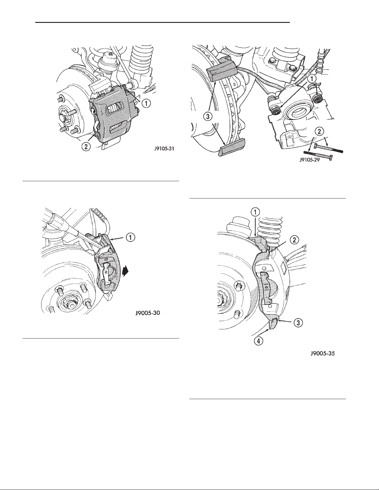
(7) Tilt top of caliper outward with pry tool if necessary (Fig. 27) and remove caliper.
1 – BUSHINGS
2 – CALIPER MOUNTING BOLTS
3 – MOUNTING LEDGES
Fig. 28 Caliper Lubrication Points
Fig. 27 Caliper Removal
1 – TILT CALIPER OUTBOARD TO REMOVE
(8) Remove caliper from vehicle.
INSTALLATION
(1) Clean brake shoe mounting ledges with wire
brush and apply light coat of Mopar multi-mileage
grease to surfaces (Fig. 28).
(2) Install caliper by position notches at lower end
of brake shoes on bottom mounting ledge. Then
rotate caliper over rotor and seat notches at upper
end of shoes on top mounting ledge (Fig. 29).
(3) Coat caliper mounting bolts with silicone
grease. Then install and tighten bolts to 15 N·m (11
ft. lbs.).
CAUTION: If new caliper bolts are being installed,
or if the original reason for repair was a drag/pull
Fig. 29 Caliper Installation
1 – TOP LEDGE
2 – BRAKESHOE TAB ON LEDGE OUTER SURFACE
3 – LEDGE SEATED IN BRAKESHOE NOTCH
4 – BOTTOM LEDGE
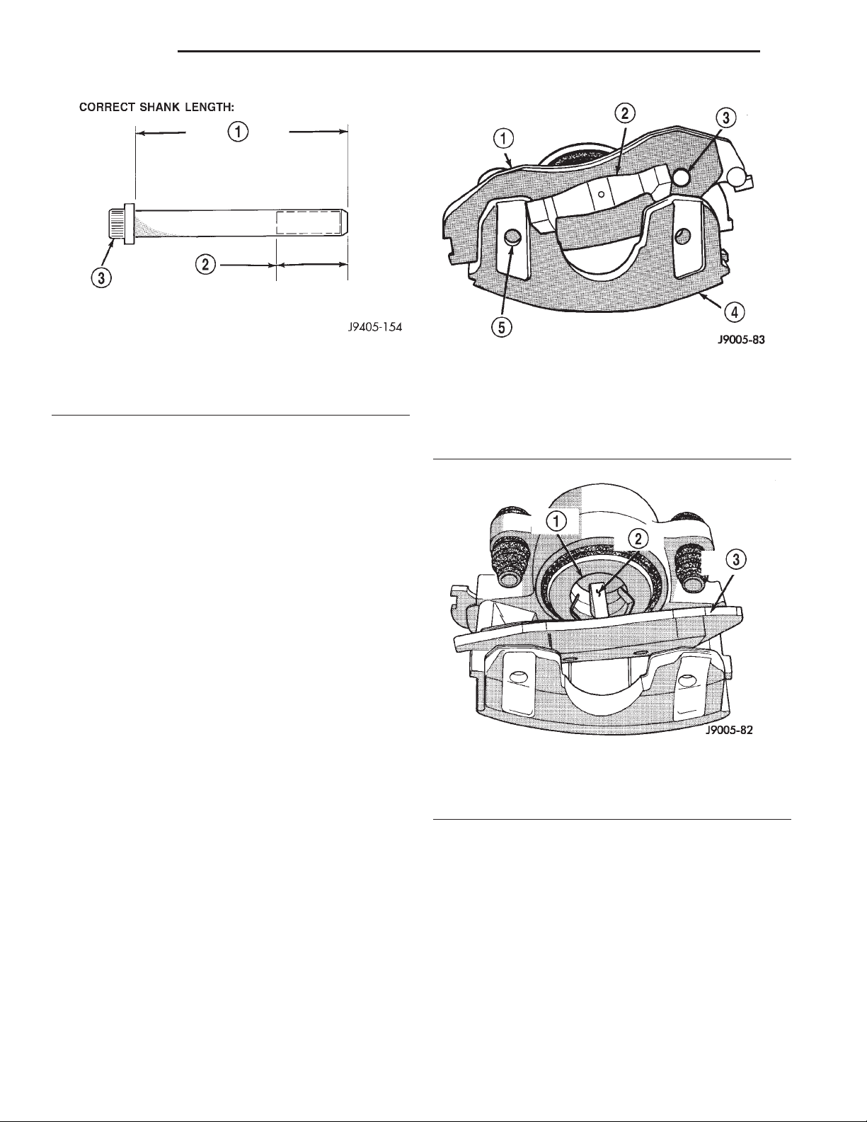
condition, check caliper bolt length before proceeding. Bolts must not have a shank length greater
than 67.6 mm (2.66 in.) (Fig. 30).
(4) Install brake hose to caliper with new seal
washers and tighten fitting bolt to 31 N·m (23 ft.
lbs.).
Page 20
5 - 20 BRAKES XJ
REMOVAL AND INSTALLATION (Continued)
Fig. 30 Mounting Bolt Dimensions
1 – 67mm(6 0.6 mm) 2.637 in. (6 0.0236 in.)
2 – 22 mm (0.866 in.) THREAD LENGTH
3 – CALIPER BOLT
CAUTION: Verify brake hose is not twisted or
kinked before tightening fitting bolt.
(5) Bleed base brake system.
(6) Install wheel and tire assemblies.
(7) Remove supports and lower vehicle.
(8) Verify firm pedal before moving vehicle.
FRONT DISC BRAKE SHOES
REMOVAL
(1) Raise and support vehicle.
(2) Remove wheel and tire assembly.
(3) Remove caliper.
(4) Pressing one end of outboard shoe inward to
disengage shoe lug. Then rotate shoe upward until
retainer spring clears caliper. Press opposite end of
shoe inward to disengage shoe lug and rotate shoe up
and out of caliper (Fig. 31).
(5) Grasp ends of inboard shoe and tilt shoe outward to release springs from caliper piston (Fig. 32)
and remove shoe from caliper.
NOTE: If original brake shoes will be used, keep
them in sets left and right. They are not interchangeable.
(6) Secure caliper to nearby suspension part with
wire. Do not allow brake hose to support caliper
weight.
(7) Wipe caliper off with shop rags or towels.
CAUTION: Do not use compressed air, this can
unseat dust boot and force dirt into piston bore.
Fig. 31 Outboard Brake Shoe Removal
1 – OUTBOARD BRAKESHOE
2 – SHOE SPRING
3 – LOCATING LUG
4 – CALIPER
5 – LOCATING LUG
Fig. 32 Inboard Brake Shoe Removal
1 – CALIPER PISTON
2 – SHOE SPRINGS
3 – INBOARD BRAKESHOE
INSTALLATION
(1) Install inboard shoe in caliper and verify shoe
retaining is fully seated into the piston.
(2) Starting one end of outboard shoe in caliper
and rotating shoe downward into place. Verify shoe
locating lugs and shoe spring are seated.
(3) Install caliper.
(4) Install wheel and tire assembly.
(5) Remove support and lower vehicle.
(6) Pump brake pedal until caliper pistons and
brake shoes are seated.
(7) Top off brake fluid level if necessary.
Page 21
XJ BRAKES 5 - 21
REMOVAL AND INSTALLATION (Continued)
DISC BRAKE ROTOR
REMOVAL
(1) Remove wheel and tire assemble.
(2) Remove caliper.
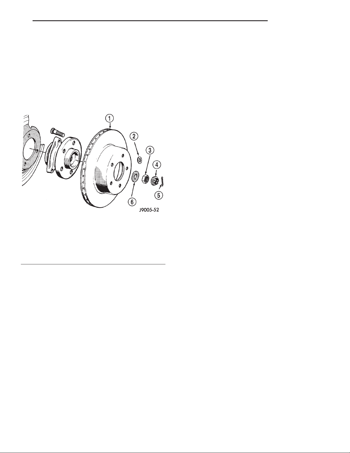
(3) Remove retainers securing rotor to hub studs
(Fig. 33).
(4) Remove rotor from hub.
(5) If rotor shield requires service, remove front
hub and bearing assembly.
Fig. 33 Rotor & Hub
1 – ROTOR
2 – RETAINER
3 – BEARING NUT
4 – NUT LOCK
5 – COTTER PIN
6 – WASHER
INSTALLATION
(1) If new rotor is being installed, remove protective coating from rotor surfaces with carburetor
cleaner.
(2) Install rotor on hub.
(3) Install caliper.
(4) Install wheel and tire assembly.
DRUM BRAKE SHOES
REMOVAL
(1) Raise vehicle and remove rear wheels.
(2) Remove and discard spring nuts securing
drums to wheel studs.
(3) Remove brake drums. If drums prove difficult
to remove, retract brake shoes. Remove access plug
at the rear of backing plate and back off adjuster
screw with brake tool and screwdriver.
(4) Remove U-clip and washer securing adjuster
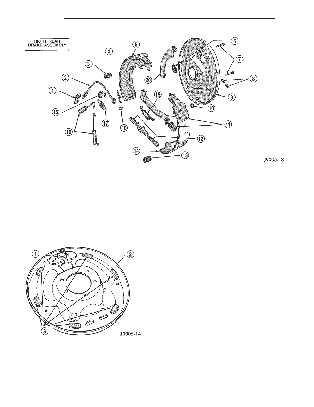
cable to parking brake lever (Fig. 34).
(5) Remove primary and secondary return springs
from anchor pin with brake spring pliers.
(6) Remove hold-down springs, retainers and pins
with standard retaining spring tool.
(7) Install spring clamps on wheel cylinders to
hold pistons in place.
(8) Remove adjuster lever, adjuster screw and
spring.
(9) Remove adjuster cable and cable guide.
(10) Remove brake shoes and parking brake strut.
(11) Disconnect cable from parking brake lever and
remove lever.
INSTALLATION
(1) Clean support plate with brake cleaner.
(2) If new drums are being installed, remove protective coating with carburetor cleaner followed by
final rinse with brake cleaner.
(3) Clean and lubricate anchor pin with light coat
of Mopar multi-mileage grease.
(4) Apply Mopar multi-mileage grease to brake
shoe contact surfaces of support plate (Fig. 35).
(5) Lubricate adjuster screw threads and pivot
with spray lube.
(6) Attach parking brake lever to secondary brake
shoe. Use new washer and U-clip to secure lever.
(7) Remove wheel cylinder clamps.
(8) Attach parking brake cable to lever.
(9) Install brake shoes on support plate. Secure
shoes with new hold-down springs, pins and retainers.
(10) Install parking brake strut and spring.
(11) Install guide plate and adjuster cable on
anchor pin.
(12) Install primary and secondary return springs.
(13) Install adjuster cable guide on secondary
shoe.
(14) Lubricate and assemble adjuster screw.
(15) Install adjuster screw, spring and lever and
connect to adjuster cable.
(16) Adjust shoes to drum.
(17) Install wheel/tire assemblies and lower vehicle.
(18) Verify firm brake pedal before moving vehicle.
WHEEL CYLINDER
REMOVAL
(1) Remove wheel and tire assembly.
(2) Remove brake drum.
(3) Disconnect wheel cylinder brake line.
(4) Remove brake shoe return springs and move
shoes out of engagement with cylinder push rods.
(5) Remove cylinder attaching bolts and remove
cylinder from support plate.
Page 22
5 - 22 BRAKES XJ
REMOVAL AND INSTALLATION (Continued)
Fig. 34 Drum Brake Components—Typical
1 – ADJUSTER LEVER
2 – ADJUSTER CABLE
3 – HOLDDOWN SPRING AND RETAINERS
4 – ADJUSTER LEVER SPRING
5 – TRAILING SHOE
6 – CYLINDER-TO-SUPPORT SEAL
7 – HOLDDOWN PINS
8 – ACCESS PLUGS
9 – SUPPORT PLATE
10 – CABLE HOLE PLUG
11 – PARK BRAKE STRUTAND SPRING
12 – ADJUSTER SCREW ASSEMBLY
13 – HOLDDOWN SPRING AND RETAINERS
14 – LEADING SHOE
15 – CABLE GUIDE
16 – SHOE RETURN SPRINGS
17 – SHOE GUIDE PLATE
18 – PIN
19 – SHOE SPRING
20 – PARK BRAKE LEVER
INSTALLATION
(1) Apply bead of silicone sealer around cylinder
mounting surface of support plate.
(2) Install cylinder mounting bolts and tighten to
20 N·m (15 ft. lbs.).
(3) Connect brake line to cylinder.
(4) Install brake shoe return spring.
(5) Install brake drum.
(6) Install wheel and tire assembly.
(7) Bleed base brake system.
BRAKE SUPPORT PLATE
Fig. 35 Shoe Contact Surfaces
1 – ANCHOR PIN
2 – SUPPORT PLATE
3 – SHOE CONTACT SURFACES
REMOVAL
(1) Remove wheel and tire assembly and brake
drum.
(2) Remove brake shoe assembly.
(3) Remove parking brake cable from parking
brake lever.
(4) Compress parking brake cable retainer tabs.
Then push retainer and cable through and out of
support plate.
Page 23
XJ BRAKES 5 - 23
REMOVAL AND INSTALLATION (Continued)
(5) Disconnect brake line at wheel cylinder.
(6) Remove wheel cylinder from support plate.
(7) Remove axle shaft, refer to Group 3 for proce-
dures.
(8) Remove bolts attaching support plate to axle
and remove support plate.
INSTALLATION
(1) Apply bead of silicone sealer around axle
mounting surface of support plate.
(2) Install support plate on axle flange. Tighten
attaching bolts to 115 N·m (85 ft. lbs.).
(3) Apply bead of silicone sealer around wheel cyl-
inder mounting surface and install wheel cylinder.
(4) Install brake line in wheel cylinder.
(5) Install parking brake cable in support plate.
(6) Install axle shaft, refer to Group 3 for proce-
dure.
(7) Connect parking brake cable to lever on sec-
ondary shoe and install brake shoes on support plate.
(8) Adjust brake shoes to drum with brake gauge.
(9) Install brake drum and wheel and tire assem-
bly.
(10) Bleed brake system.
1 – REAR CABLES
2 – EQUALIZER
3 – FRONT CABLE
4 – TENSIONER ROD
Fig. 36 Parking Brake Cables
REAR PARKING BRAKE CABLES
REMOVAL
(1) Raise vehicle and loosen equalizer nuts until
rear cables are slack.
(2) Disengage cables from equalizer and compress
cable retainers with a worm drive hose clamp.
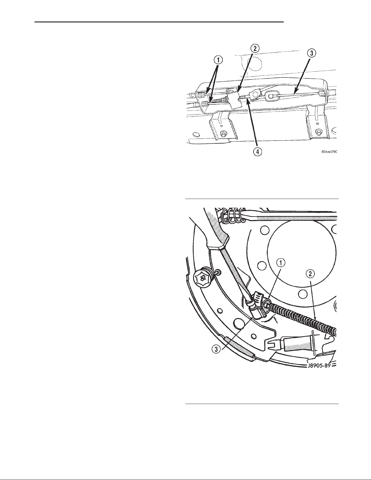
(3) Remove cables from the cable bracket (Fig. 36).
(4) Remove rear wheel and brake drums.
(5) Remove secondary brake shoe and disconnect
cable from lever on brake shoe.
(6) Compress cables retainer with worm drive hose
clamp (Fig. 37) and remove cables from backing
plates.
INSTALLATION
(1) Install new cables in backing plates. Be sure
cable retainer is seated.
(2) Attach cable to lever on brake shoe and install
brake shoe on backing plate.
(3) Adjust brake shoes to drum with brake gauge.
(4) Install brake drums and wheels.
(5) Install cables into the cable bracket and insure
retainers are seated in the bracket.
(6) Engage the cable ends into the equalizer and
install equalizer nut.
(7) Adjust parking brakes.
Fig. 37 Cable Retainer
1 – CABLE RETAINER
2 – REAR CABLE
3 – WORM DRIVE HOSE CLAMP
PARKING BRAKE LEVER
The center console must be removed to service the
parking brake lever. Refer to Group 23 Interior Components for service procedures.
Page 24
5 - 24 BRAKES XJ
REMOVAL AND INSTALLATION (Continued)
REMOVAL
(1) Release parking brakes.
(2) Raise vehicle.
(3) Remove adjusting nut from tensioner rod at the
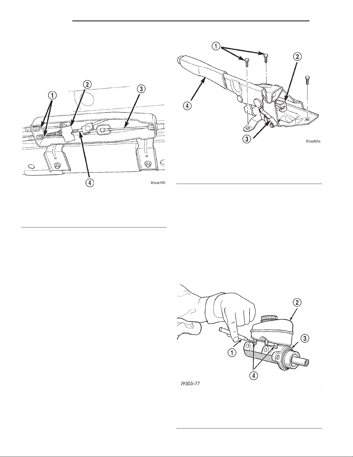
equalizer (Fig. 38).
Fig. 39 Parking Brake Lever Assembly
1 – MOUNTING BOLTS
2 – FRONT CABLE LEVER
3 – PARKING BRAKE SWITCH
4 – PARKING BRAKE LEVER
Fig. 38 Parking Brake Equalizer
1 – REAR CABLES
2 – EQUALIZER
3 – FRONT CABLE
4 – TENSIONER ROD
(4) Lower vehicle.
(5) Disengage front cable from the cable lever.
(6) Compress cable retainer with worm drive hose
clamp and remove the cable from the parking brake
lever base.
(7) Disconnect parking brake lamp switch wire
(Fig. 39).
(8) Remove parking brake lever assembly mounting bolts (Fig. 39).
(9) Remove lever assembly.
(10) Remove parking brake lamp switch.
INSTALLATION
(1) Install parking brake lamp switch.
(2) Position lever assembly on floorpan and install
lever mounting bolts.
(3) Tighten lever mounting bolts to 10 to 14 N·m
(7 to 10 ft. lbs.).
(4) Insert front cable through the parking brake
lever base. Insure the cable retainer is seated into
the base.
(5) Attach the front cable to the cable lever (Fig.
39).
(6) Connect parking brake lamp switch wire.
(7) Raise vehicle.
(8) Install adjusting nut to the tensioner rod and
adjust parking brakes.
(9) Lower vehicle.
(10) Verify correct parking brake operation.
DISASSEMBLY AND ASSEMBLY
MASTER CYLINDER RESERVOIR
REMOVAL
(1) Remove reservoir cap and empty fluid into
drain container.
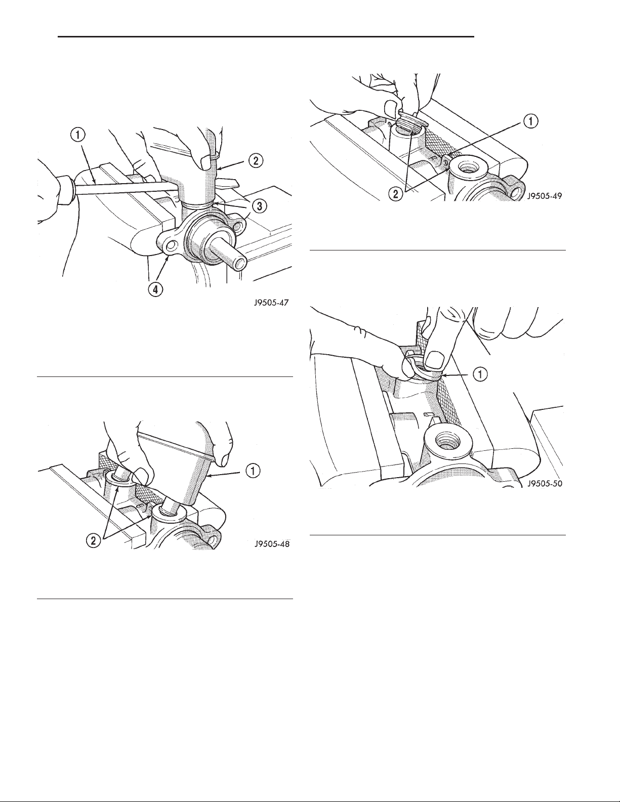
(2) Remove pins that retain reservoir to master
cylinder. Use hammer and pin punch to remove pins
(Fig. 40).
Fig. 40 Reservoir Retaining Pins
1 – PIN PUNCH
2 – RESERVOIR
3 – BODY
4 – ROLL PINS
Page 25
XJ BRAKES 5 - 25
DISASSEMBLY AND ASSEMBLY (Continued)
(3) Clamp cylinder body in vise with brass protec-
tive jaws.
(4) Loosen reservoir from grommets with pry tool
(Fig. 41).
Fig. 43 Grommet Removal
1 – MASTER CYLINDER BODY
2 – GROMMETS
(1) Lubricate new grommets with clean brake fluid
and Install new grommets in cylinder body (Fig. 44).
Use finger pressure to install and seat grommets.
Fig. 41 Loosening Reservoir
1–PRYTOOL
2 – RESERVOIR
3 – GROMMET
4 – MASTER CYLINDER BODY
(5) Remove reservoir by rocking it to one side and
pulling free of grommets (Fig. 42).
Fig. 42 Reservoir Removal
1 – RESERVOIR
2 – GROMMETS
(6) Remove old grommets from cylinder body (Fig.
43).
INSTALLATION
CAUTION: Do not use any type of tool to install the
grommets. Tools may cut, or tear the grommets creating a leak problem after installation. Install the
grommets using finger pressure only.
Fig. 44 Grommet Installation
1 – WORK NEW GROMMETS INTO PLACE USING FINGER
PRESSURE ONLY
(2) Start reservoir in grommets. Then rock reservoir back and forth while pressing downward to seat
it in grommets.
(3) Install pins that retain reservoir to cylinder
body.
(4) Fill and bleed master cylinder on bench before
installation in vehicle.
DISC BRAKE CALIPER
DISASSEMBLY
(1) Remove brake shoes from caliper.
(2) Drain brake fluid out of caliper.
(3) Take a piece of wood and pad it with one-inch
thickness of shop towels. Place this piece in the outboard shoe side of the caliper in front of the piston.
Page 26
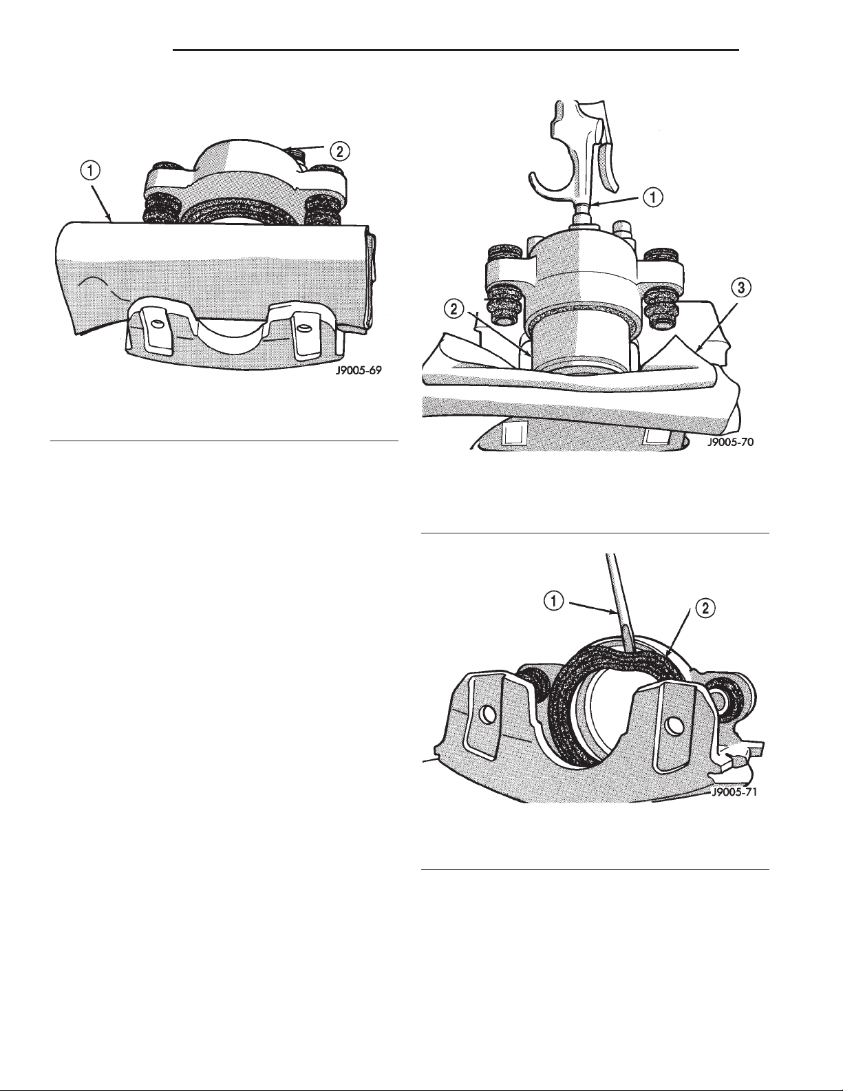
5 - 26 BRAKES XJ
DISASSEMBLY AND ASSEMBLY (Continued)
This will cushion and protect caliper piston during
removal (Fig. 45).
Fig. 45 Padding Caliper Interior
1 – SHOP TOWELS OR CLOTHS
2 – CALIPER
(4) Remove caliper piston with short bursts of
low pressure compressed air. Direct air through fluid
inlet port and ease piston out of bore (Fig. 46).
CAUTION: Do not blow the piston out of the bore
with sustained air pressure. This could result in a
cracked piston. Use only enough air pressure to
ease the piston out.
WARNING: NEVER ATTEMPT TO CATCH THE PISTON AS IT LEAVES THE BORE. THIS MAY RESULT
IN PERSONAL INJURY.
(5) Remove caliper piston dust boot with suitable
pry tool (Fig. 47).
(6) Remove caliper piston seal with wood or plastic
tool (Fig. 48). Do not use metal tools as they will
scratch piston bore.
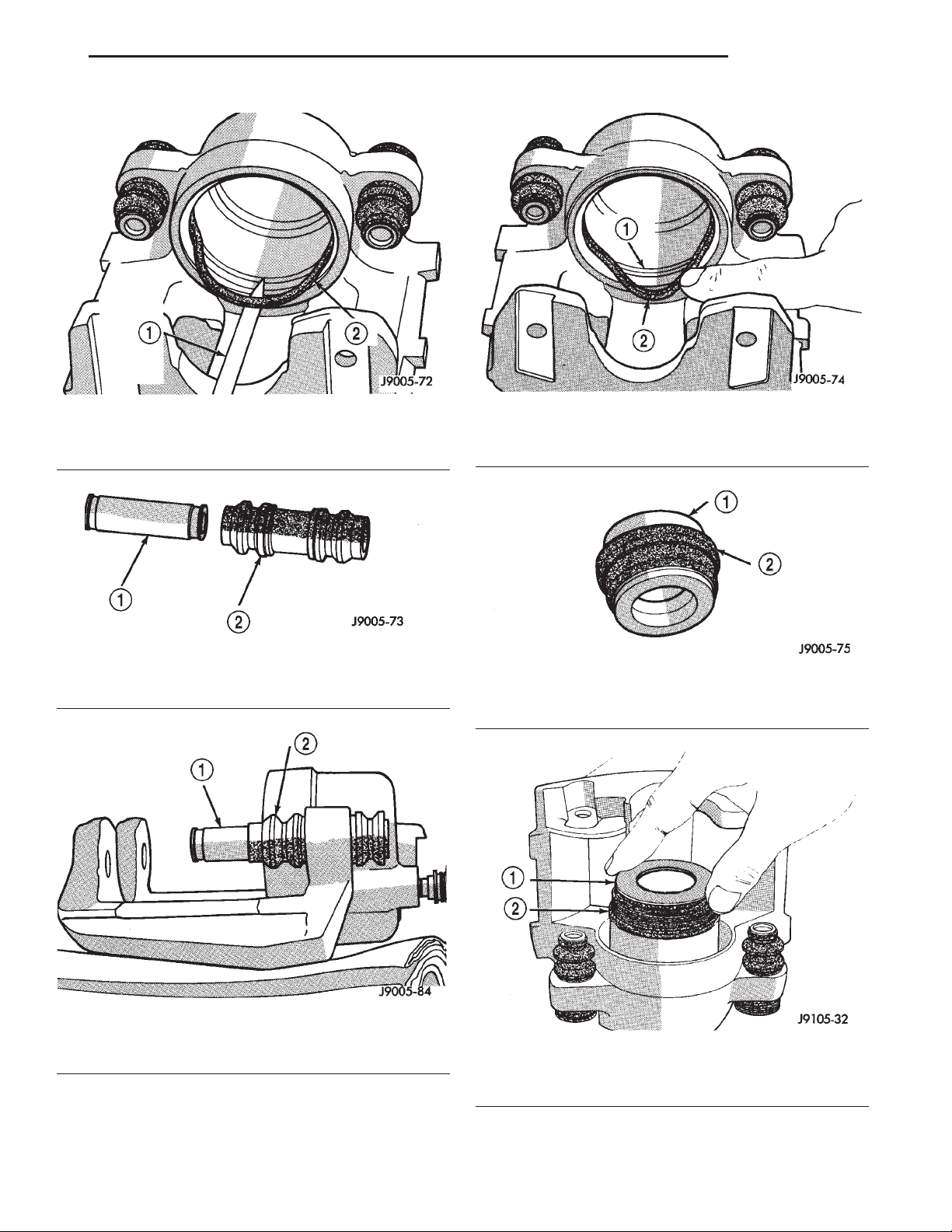
(7) Remove caliper mounting bolt bushings and
boots (Fig. 49).
ASSEMBLY
CAUTION: Dirt, oil, and solvents can damage caliper seals. Insure assembly area is clean and dry.
Fig. 46 Caliper Piston Removal
1 – AIR GUN
2 – CALIPER PISTON
3 – PADDING MATERIAL
Fig. 47 Caliper Piston Dust Boot Removal
1 – COLLAPSE BOOT WITH PUNCH OR SCREWDRIVER
2 – PISTON DUST BOOT
(1) Lubricate caliper piston bore, new piston seal
and piston with clean brake fluid.
(2) Lubricate caliper bushings and interior of
bushing boots with silicone grease.
(3) Install bushing boots in caliper, then insert
bushing into boot and push bushing into place (Fig.
50).
(4) Install new piston seal into seal groove with
finger (Fig. 51).
(5) Install new dust boot on caliper piston and seat
boot in piston groove (Fig. 52).
(6) Press piston into caliper bore by hand, use a
turn and push motion to work piston into seal (Fig.
53).
(7) Press caliper piston to bottom of bore.
Page 27
XJ BRAKES 5 - 27
DISASSEMBLY AND ASSEMBLY (Continued)
Fig. 48 Piston Seal Removal
1 – REMOVE SEAL WITH WOOD PENCIL OR SIMILAR TOOL
2 – PISTON SEAL
Fig. 49 Mounting Bolt Bushing And Boot
1 – CALIPER SLIDE BUSHING
2 – BOOT
Fig. 51 Piston Seal Installation
1 – SEAL GROOVE
2 – PISTON SEAL
Fig. 52 Dust Boot On Piston
1 – PISTON
2 – DUST BOOT
Fig. 50 Bushings And Boots Installation
1 – BUSHING
2 – BOOT
Fig. 53 Caliper Piston Installation
1 – PISTON
2 – BOOT
Page 28
5 - 28 BRAKES XJ
DISASSEMBLY AND ASSEMBLY (Continued)
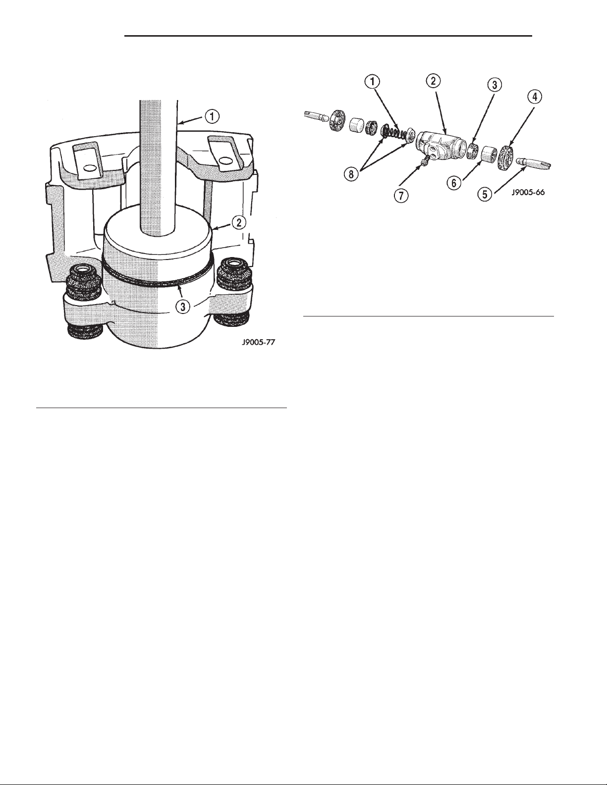
(8) Seat dust boot in caliper with Installer Tool
C-4842 and Tool Handle C-4171 (Fig. 54).
Fig. 55 Wheel Cylinder Components–Typical
1 – SPRING
2 – CYLINDER
3 – PISTON CLIP
4 – BOOT
5 – PUSH ROD
6 – PISTON
7 – BLEED SCREW
8 – CUP EXPANDERS
Fig. 54 Piston Dust Boot Installation
1 – HANDLE C-4171
2 – INSTALLER C-4842
3 – DUST BOOT
(9) Replace caliper bleed screw if removed.
WHEEL CYLINDER
DISASSEMBLY
(1) Remove push rods and boots (Fig. 55).
(2) Press pistons, cups and spring and expander
out of cylinder bore.
(3) Remove bleed screw.
ASSEMBLY
(1) Lubricate wheel cylinder bore, pistons, piston
cups and spring and expander with clean brake fluid.
(2) Install first piston in cylinder bore. Then
install first cup in bore and against piston. Be sure
lip of piston cup is facing inward (toward
spring and expander) and flat side is against
piston.
(3) Install spring and expander followed by
remaining piston cup and piston.
(4) Install boots on each end of cylinder and insert
push rods in boots.
(5) Install cylinder bleed screw.
CLEANING AND INSPECTION
CALIPER
CLEANING
Clean the caliper components with clean brake
fluid or brake clean only. Wipe the caliper and piston
dry with lint free towels or use low pressure compressed air.
CAUTION: Do not use gasoline, kerosene, thinner,
or similar solvents. These products may leave a
residue that could damage the piston and seal.
INSPECTION
The piston is made from a phenolic resin (plastic
material) and should be smooth and clean.
The piston must be replaced if cracked or scored.
Do not attempt to restore a scored piston surface by
sanding or polishing.
CAUTION: If the caliper piston is replaced, install
the same type of piston in the caliper. Never interchange phenolic resin and steel caliper pistons.
The pistons, seals, seal grooves, caliper bore and
piston tolerances are different.
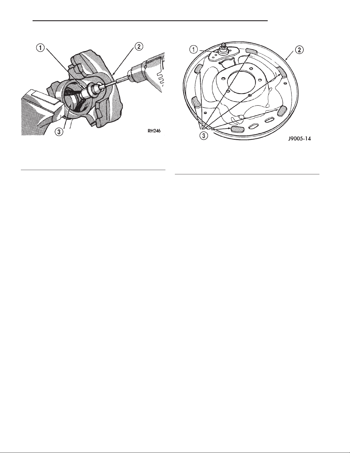
The bore can be lightly polished with a brake
hone to remove very minor surface imperfections
(Fig. 56). The caliper should be replaced if the bore is
severely corroded, rusted, scored, or if polishing
would increase bore diameter more than 0.025 mm
(0.001 inch).
Page 29
XJ BRAKES 5 - 29
CLEANING AND INSPECTION (Continued)
Fig. 56 Polishing Piston Bore
1 – SPECIAL HONE
2 – CALIPER
3 – PISTON BORE
REAR DRUM BRAKE
CLEANING
Clean the individual brake components, including
the support plate and wheel cylinder exterior, with a
water dampened cloth or with brake cleaner. Do not
use any other cleaning agents. Remove light rust and
scale from the brake shoe contact pads on the support plate with fine sandpaper.
INSPECTION
As a general rule, riveted brake shoes should be
replaced when worn to within 0.78 mm (1/32 in.) of
the rivet heads. Bonded lining should be replaced
when worn to a thickness of 1.6 mm (1/16 in.).
Examine the lining contact pattern to determine if
the shoes are bent or the drum is tapered. The lining
should exhibit contact across its entire width. Shoes
exhibiting contact only on one side should be
replaced and the drum checked for runout or taper.
Inspect the adjuster screw assembly. Replace the
assembly if the star wheel or threads are damaged,
or the components are severely rusted or corroded.
Discard the brake springs and retainer components
if worn, distorted or collapsed. Also replace the
springs if a brake drag condition had occurred. Overheating will distort and weaken the springs.
Inspect the brake shoe contact pads on the support
plate, replace the support plate if any of the pads are
worn or rusted through. Also replace the plate if it is
bent or distorted (Fig. 57).
Fig. 57 Shoe Contact Surfaces
1 – ANCHOR PIN
2 – SUPPORT PLATE
3 – SHOE CONTACT SURFACES
WHEEL CYLINDER
CLEANING
Clean the cylinder and pistons with clean brake
fluid or brake cleaner only. Do not use any other
cleaning agents.
Dry the cylinder and pistons with compressed air.
Do not use rags or shop towels to dry the cylinder
components. Lint from cloth material will adhere to
the cylinder bores and pistons.
INSPECTION
Inspect the cylinder bore. Light discoloration and
dark stains in the bore are normal and will not
impair cylinder operation.
The cylinder bore can be lightly polished but only
with crocus cloth. Replace the cylinder if the bore is
scored, pitted or heavily corroded. Honing the bore to
restore the surface is not recommended.
Inspect the cylinder pistons. The piston surfaces
should be smooth and free of scratches, scoring and
corrosion. Replace the pistons if worn, scored, or corroded. Do attempt to restore the surface by sanding
or polishing.
Discard the old piston cups and the spring and
expander. These parts are not reusable. The original
dust boots may be reused but only if they are in good
condition.
Page 30
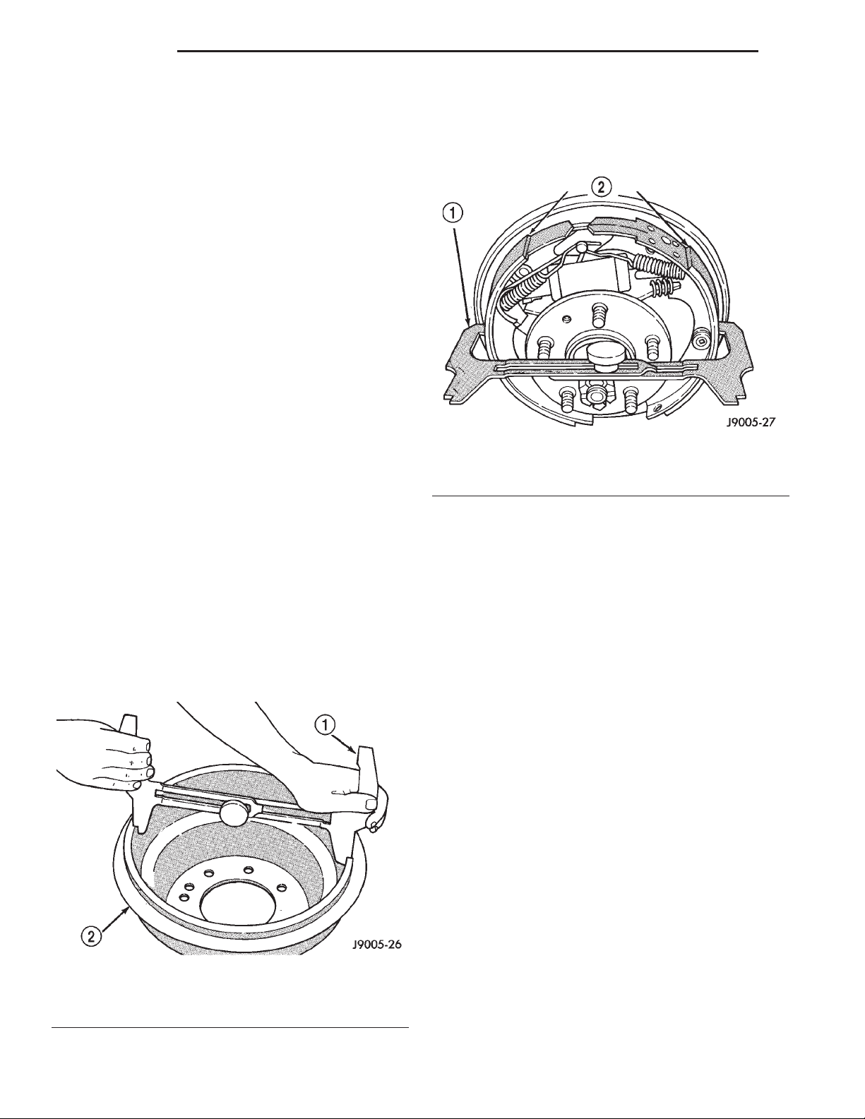
5 - 30 BRAKES XJ
ADJUSTMENTS
BRAKE LAMP SWITCH
(1) Press and hold brake pedal in applied position.
(2) Pull switch plunger all the way out to fully
extended position.
(3) Release brake pedal. Then pull pedal lightly
rearward. Pedal will set plunger to correct position
as pedal pushes plunger into switch body. Switch will
make ratcheting sound as it self adjusts.
CAUTION: Booster damage may occur if the pedal
pull exceeds 20 lbs..
REAR DRUM BRAKE
The rear drum brakes are equipped with a self-adjusting mechanism. Under normal circumstances, the
only time adjustment is required is when the shoes
are replaced, removed for access to other parts, or
when one or both drums are replaced.
Adjustment can be made with a standard brake
gauge or with adjusting tool. Adjustment is performed with the complete brake assembly installed
on the backing plate.
ADJUSTMENT WITH BRAKE GAUGE
(1) Be sure parking brakes are fully released.
(2) Raise rear of vehicle and remove wheels and
brake drums.
(3) Verify that left and right automatic adjuster
levers and cables are properly connected.
(4) Insert brake gauge in drum. Expand gauge
until gauge inner legs contact drum braking surface.
Then lock gauge in position (Fig. 58).
(5) Reverse gauge and install it on brake shoes.
Position gauge legs at shoe centers as shown (Fig.
59). If gauge does not fit (too loose/too tight), adjust
shoes.
Fig. 59 Adjusting Gauge On Brake Shoes
1 – BRAKE GAUGE
2 – BRAKE SHOES
(6) Pull shoe adjuster lever away from adjuster
screw star wheel.
(7) Turn adjuster screw star wheel (by hand) to
expand or retract brake shoes. Continue adjustment
until gauge outside legs are light drag-fit on shoes.
(8) Install brake drums and wheels and lower
vehicle.
(9) Drive vehicle and make one forward stop followed by one reverse stop. Repeat procedure 8-10
times to operate automatic adjusters and equalize
adjustment.
Fig. 58 Adjusting Gauge On Drum
1 – BRAKE GAUGE
2 – BRAKE DRUM
NOTE: Bring vehicle to complete standstill at each
stop. Incomplete, rolling stops will not activate
automatic adjusters.
ADJUSTMENT WITH ADJUSTING TOOL
(1) Be sure parking brake lever is fully released.
(2) Raise vehicle so rear wheels can be rotated
freely.
(3) Remove plug from each access hole in brake
support plates.
(4) Loosen parking brake cable adjustment nut
until there is slack in front cable.
(5) Insert adjusting tool through support plate
access hole and engage tool in teeth of adjusting
screw star wheel (Fig. 60).
(6) Rotate adjuster screw star wheel (move tool
handle upward) until slight drag can be felt when
wheel is rotated.
Page 31
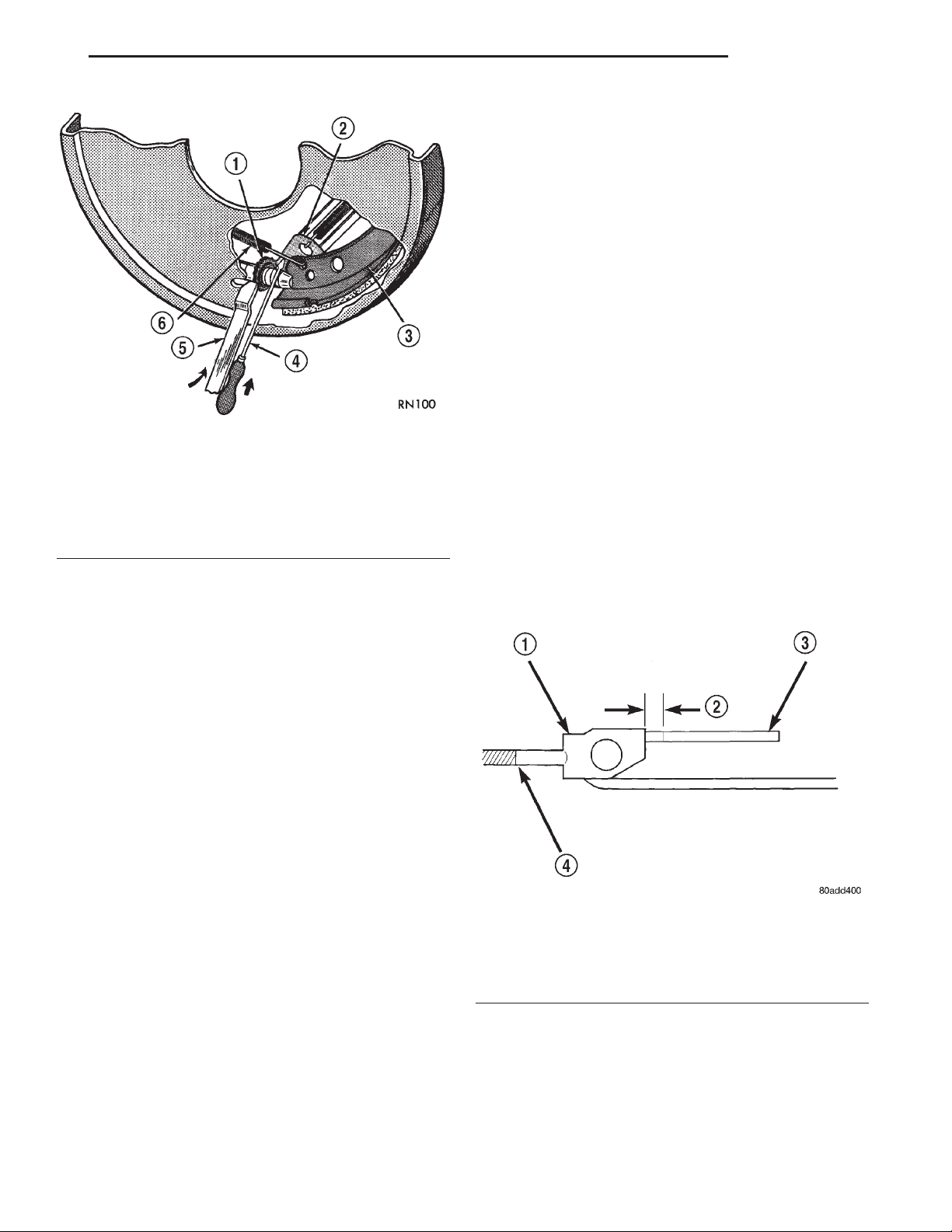
XJ BRAKES 5 - 31
ADJUSTMENTS (Continued)
(4) Check rear brake shoe adjustment with standard brake gauge.
CAUTION: Excessive shoe-to-drum clearance, or
worn brake components will result in faulty parking
brake adjustment and operation.
(5) Verify that parking brake cables operate freely
and are not binding, or seized. Replace faulty cables,
before proceeding.
(6) Reinstall brake drums and wheel/tire assemblies after brake shoe adjustment is complete.
(7) Lower vehicle enough for access to parking
brake lever. Then fully apply parking brakes. Leave
brakes applied until adjustment is complete.
(8) Raise vehicle and mark tensioner rod 6.5 mm
(1/4 in.) from tensioner bracket (Fig. 61).
Fig. 60 Brake Adjustment
1 – STAR WHEEL
2 – LEVER
3 – BRAKE SHOE WEB
4 – SCREWDRIVER
5 – ADJUSTING TOOL
6 – ADJUSTER SPRING
(9) Tighten adjusting nut at equalizer until mark
on tensioner rod moves into alignment with tensioner
bracket.
(10) Lower vehicle until rear wheels are 15-20 cm
(6-8 in.) off shop floor.
(11) Release parking brake lever and verify that
rear wheels rotate freely without drag.
(12) Lower vehicle.
(7) Push and hold adjuster lever away from star
wheel with thin screwdriver.
(8) Back off adjuster screw star wheel until brake
drag is eliminated.
(9) Repeat adjustment at opposite wheel. Be sure
adjustment is equal at both wheels.
(10) Install support plate access hole plugs.
(11) Adjust parking brake cable and lower vehicle.
(12) Drive vehicle and make one forward stop followed by one reverse stop. Repeat procedure 8-10
times to operate automatic adjusters and equalize
adjustment.
NOTE: Bring vehicle to complete standstill at each
stop. Incomplete, rolling stops will not activate
automatic adjusters.
PARKING BRAKE CABLE TENSIONER
NOTE: Parking brake adjustment is only necessary
when the tensioner, or a cable has been replaced or
disconnected.
ADJUSTMENT
(1) Raise vehicle.
(2) Back off tensioner adjusting nut to create slack
in cables.
(3) Remove rear wheel/tire assemblies and remove
brake drums.
NOTE: Do not loosen/tighten equalizer adjusting
nut for any reason after completing adjustment.
Fig. 61 Tensioner Rod Measurement
1 – TENSIONER BRACKET
2 – 6.5 mm (1/4 in.)
3 – TENSIONER ROD
4 – ROD TO EQUALIZER
SPECIFICATIONS
BRAKE FLUID
The brake fluid used in this vehicle must conform
to DOT 3 specifications and SAE J1703 standards.
No other type of brake fluid is recommended or
approved for usage in the vehicle brake system. Use
Page 32
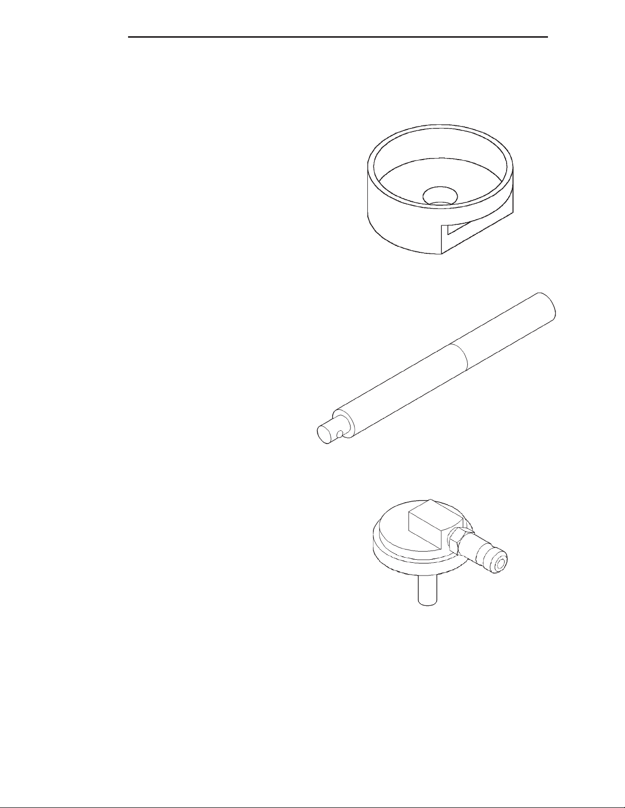
5 - 32 BRAKES XJ
SPECIFICATIONS (Continued)
only Mopar brake fluid or an equivalent from a
tightly sealed container.
CAUTION: Never use reclaimed brake fluid or fluid
from an container which has been left open. An
open container will absorb moisture from the air
and contaminate the fluid.
CAUTION: Never use any type of a petroleumbased fluid in the brake hydraulic system. Use of
such type fluids will result in seal damage of the
vehicle brake hydraulic system causing a failure of
the vehicle brake system. Petroleum based fluids
would be items such as engine oil, transmission
fluid, power steering fluid, etc.
BRAKE COMPONENTS
Disc Brake Caliper
Type............................. Sliding
Disc Brake Rotor
Type .......................... Ventilated
Max. Runout ............. 0.12 mm (0.005 in.)
Max. Thickness Variation . . 0.013 mm (0.0005 in.)
Min. Thickness .......... 22.7 mm (0.8937 in.)
Brake Drum
Size ........................ 9in.or10in.
Brake Booster
Type ..................... Dual Diaphragm
SPECIAL TOOLS
BASE BRAKES
Installer Caliper Dust Boot 8280
TORQUE CHART
DESCRIPTION TORQUE
Brake Pedal
Pivot Bolt/Nut ............ 35N·m(26ft.lbs.)
Brake Booster
Mounting Nuts ........... 39N·m(29ft.lbs.)
Master Cylinder
Mounting Nuts ......... 17.5 N·m (155 in. lbs.)
Brake Lines ............. 14N·m(124 in. lbs.)
Combination Valve
Mounting Nuts ......... 17.5 N·m (155 in. lbs.)
Brake Lines ............. 14N·m(124 in. lbs.)
Caliper
Mounting Bolts ........... 15N·m(11ft.lbs.)
Brake Hose Bolt ........... 31N·m(23ft.lbs.)
Wheel Cylinder
Mounting Bolts ............ 10N·m(7ft.lbs.)
Brake Line ............. 14N·m(124 in. lbs.)
Parking Brake
Lever Screws ......... 10-14 N·m (7-10 ft. lbs.)
Lever Bracket Screws . . 10-14 N·m (7-10 ft. lbs.)
Cable Retainer Nut ....... 1.5N·m(14in.lbs.)
Handle C-4171
Adapter Pressure Bleeder 6921
Page 33

XJ BRAKES 5 - 33
ANTILOCK BRAKES
TABLE OF CONTENTS
page page
DESCRIPTION AND OPERATION
ANTILOCK BRAKE SYSTEM ................33
CONTROLLER ANTILOCK BRAKES...........33
HYDRAULIC CONTROL UNIT................34
WHEEL SPEED SENSORS AND TONE WHEEL . . 34
COMBINATION VALVE.....................35
G-SWITCH..............................35
ABS WARNING LAMP .....................35
DIAGNOSIS AND TESTING
ANTILOCK BRAKES.......................36
SERVICE PROCEDURES
BLEEDING ABS BRAKE SYSTEM ............36
DESCRIPTION AND OPERATION
ANTILOCK BRAKE SYSTEM
DESCRIPTION
The purpose of the antilock system is to prevent
wheel lockup during periods of high wheel slip. Preventing lockup helps maintain vehicle braking action
and steering control.
The antilock CAB activates the system whenever
sensor signals indicate periods of high wheel slip.
High wheel slip can be described as the point where
wheel rotation begins approaching 20 to 30 percent of
actual vehicle speed during braking. Periods of high
wheel slip occur when brake stops involve high pedal
pressure and rate of vehicle deceleration.
Battery voltage is supplied to the CAB ignition terminal when the ignition switch is turned to Run position. The CAB performs a system initialization
procedure at this point. Initialization consists of a
static and dynamic self check of system electrical
components.
The static check occurs after the ignition switch is
turned to Run position. The dynamic check occurs
when vehicle road speed reaches approximately 30
kph (18 mph). During the dynamic check, the CAB
briefly cycles the pump and solenoids to verify operation.
If an ABS component exhibits a fault during initialization, the CAB illuminates the amber warning
light and registers a fault code in the microprocessor
memory.
REMOVAL AND INSTALLATION
HYDRAULIC CONTROL UNIT/CONTROLLER
ANTILOCK BRAKES .....................36
FRONT WHEEL SPEED SENSOR ............37
REAR WHEEL SPEED SENSOR .............37
G-SWITCH..............................38
DISASSEMBLY AND ASSEMBLY
HYDRAULIC CONTROL UNIT/CONTROLLER
ANTILOCK BRAKE ......................39
SPECIFICATIONS
T0RQUE CHART .........................40
would in a vehicle without ABS. The HCU components are not activated.
During antilock braking fluid pressure is modulated according to wheel speed, degree of slip and
rate of deceleration. A sensor at each wheel converts
wheel speed into electrical signals. These signals are
transmitted to the CAB for processing and determination of wheel slip and deceleration rate.
The ABS system has three fluid pressure control
channels. The front brakes are controlled separately
and the rear brakes in tandem. A speed sensor input
signal indicating a high slip condition activates the
CAB antilock program. Two solenoid valves are used
in each antilock control channel. The valves are all
located within the HCU valve body and work in pairs
to either increase, hold, or decrease apply pressure as
needed in the individual control channels. The solenoid valves are not static during antilock braking.
They are cycled continuously to modulate pressure.
Solenoid cycle time in antilock mode can be measured in milliseconds.
CONTROLLER ANTILOCK BRAKES
DESCRIPTION
The CAB is mounted to the HCU and operates the
ABS system (Fig. 1) separate from other vehicle electrical circuits.
OPERATION
The CAB voltage source is through the ignition
switch in the RUN position. The CAB contains dual
OPERATION
During normal braking, the master cylinder, power
booster and wheel brake units all function as they
Page 34
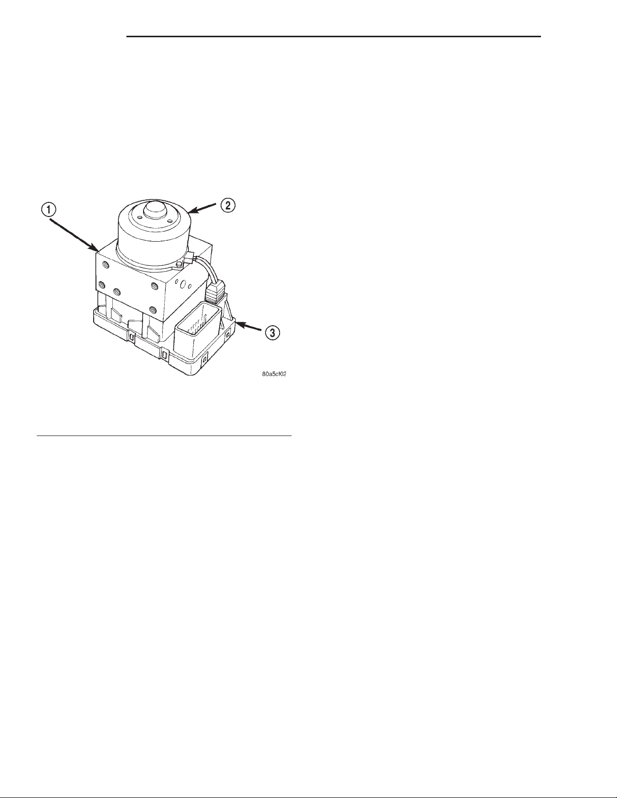
5 - 34 BRAKES XJ
DESCRIPTION AND OPERATION (Continued)
microprocessors. A logic block in each microprocessor
receives identical sensor signals. These signals are
processed and compared simultaneously. The CAB
contains a self check program that illuminates the
ABS warning light when a system fault is detected.
Faults are stored in a diagnostic program memory
and are accessible with the DRB scan tool. ABS
faults remain in memory until cleared, or until after
the vehicle is started approximately 50 times. Stored
faults are not erased if the battery is disconnected.
Fig. 1 Controller Antilock Brakes
1 – HCU
2 – MOTOR
3 – CAB
HYDRAULIC CONTROL UNIT
DESCRIPTION
The HCU consists of a valve body, pump motor,
and wire harness (Fig. 1).
power booster operate the same as a vehicle without
an ABS brake system.
During antilock braking, solenoid valve pressure
modulation occurs in three stages, pressure increase,
pressure hold, and pressure decrease. The valves are
all contained in the valve body portion of the HCU.
PRESSURE DECREASE
The outlet valve is opened and the inlet valve is
closed during the pressure decrease cycle.
A pressure decrease cycle is initiated when speed
sensor signals indicate high wheel slip at one or
more wheels. At this point, the CAB closes the inlet
then opens the outlet valve, which also opens the
return circuit to the accumulators. Fluid pressure is
allowed to bleed off (decrease) as needed to prevent
wheel lock.
Once the period of high wheel slip has ended, the
CAB closes the outlet valve and begins a pressure
increase or hold cycle as needed.
PRESSURE HOLD
Both solenoid valves are closed in the pressure
hold cycle. Fluid apply pressure in the control channel is maintained at a constant rate. The CAB maintains the hold cycle until sensor inputs indicate a
pressure change is necessary.
PRESSURE INCREASE
The inlet valve is open and the outlet valve is
closed during the pressure increase cycle. The pressure increase cycle is used to counteract unequal
wheel speeds. This cycle controls re-application of
fluid apply pressure due to changing road surfaces or
wheel speed.
WHEEL SPEED SENSORS AND TONE WHEEL
OPERATION
Accumulators in the valve body store extra fluid
released to the system for ABS mode operation. The
pump provides the fluid volume needed and is operated by a DC type motor. The motor is controlled by
the CAB.
The valves modulate brake pressure during
antilock braking and are controlled by the CAB.
The HCU provides three channel pressure control
to the front and rear brakes. One channel controls
the rear wheel brakes in tandem. The two remaining
channels control the front wheel brakes individually.
During antilock braking, the solenoid valves are
opened and closed as needed. The valves are not
static. They are cycled rapidly and continuously to
modulate pressure and control wheel slip and deceleration.
During normal braking, the HCU solenoid valves
and pump are not activated. The master cylinder and
DESCRIPTION
A speed sensor is used at each wheel. The front
sensors are mounted to the steering knuckles. The
rear sensors at the outboard end of the axle.
OPERATION
The sensors convert wheel speed into a small AC
electrical signal. This signal is transmitted to the
CAB. The CAB converts the AC signal into a digital
signal for each wheel. This voltage is generated by
magnetic induction when a tone wheel passes by the
stationary magnet of the wheel speed sensor.
A gear type tone ring serves as the trigger mechanism for each sensor. The tone rings are mounted at
the outboard ends of the front and rear axle shafts.
Different sensors are used at the front and rear
wheels (Fig. 2). The front/rear sensors have the same
electrical values but are not interchangeable. The
Page 35
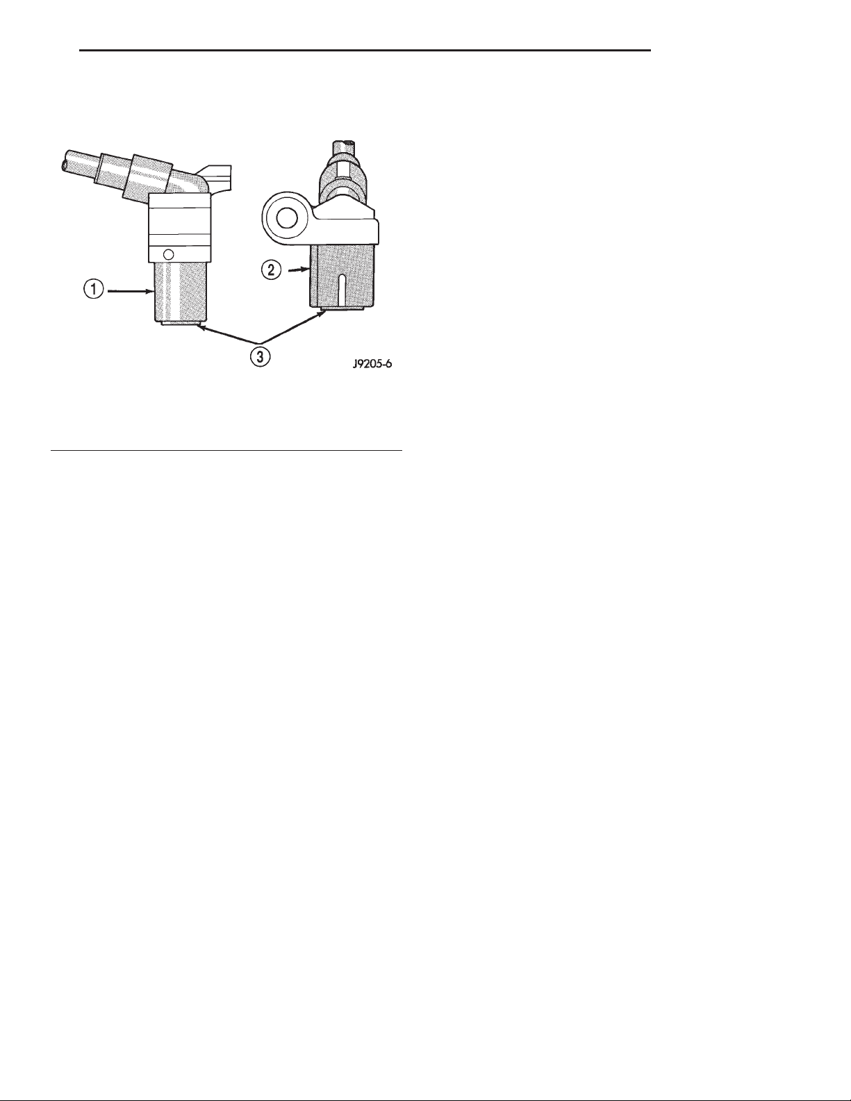
XJ BRAKES 5 - 35
DESCRIPTION AND OPERATION (Continued)
sensors have a resistance between 900 and 1300
ohms.
Fig. 2 Wheel Speed Sensors
1 – FRONT SENSOR
2 – REAR SENSOR
3 – PICKUP FACE
FRONT SENSOR AIR GAP
Front sensor air gap is fixed and not adjustable.
Only rear sensor air gap is adjustable.
Although front air gap is not adjustable, it can be
checked if diagnosis indicates this is necessary. Front
air gap should be 0.36 to 1.5 mm (0.014 to 0.059 in.). If
gap is incorrect, the sensor is either loose, or damaged.
REAR SENSOR AIR GAP
A rear sensor air gap adjustment is only needed
when reinstalling an original sensor. Replacement
sensors have an air gap spacer attached to the sensor
pickup face. The spacer establishes correct air gap
when pressed against the tone ring during installation. As the tone ring rotates, it peels the spacer off
the sensor to create the required air gap. Rear sensor
air gap is 0.92-1.275 mm (0.036-0.05 in.).
Sensor air gap measurement, or adjustment procedures are provided in this section. Refer to the front,
or rear sensor removal and installation procedures as
required.
COMBINATION VALVE
DESCRIPTION
The combination valve contains a pressure differential valve and switch and a rear brake proportioning valve. The valve is not repairable and must be
replaced as an assembly if diagnosis indicates this is
necessary.
OPERATION
PRESSURE DIFFERENTIAL VALVE
The pressure differential switch is connected to the
brake warning light. The switch is actuated by movement of the switch valve. The switch monitors fluid
pressure in the separate front/rear brake hydraulic
circuits.
A decrease or loss of fluid pressure in either
hydraulic circuit will cause the switch valve to shuttle to the low pressure side. Movement of the valve
pushes the switch plunger upward. This action closes
the switch internal contacts completing the electrical
circuit to the red warning light. The switch valve will
remain in an actuated position until repairs to the
brake system are made.
PROPORTIONING VALVE
The proportioning valve is used to balance frontrear brake action at high decelerations. The valve
allows normal fluid flow during moderate braking.
The valve only controls fluid flow during high decelerations brake stops.
G-SWITCH
DESCRIPTION
The G-switch is located under the rear seat. The
switch has directional arrow and must be mounted
with the arrow pointing towards the front of the
vehicle.
OPERATION
The switch (Fig. 3), provides an additional vehicle
deceleration reference during 4x4 operation. The
switch is monitored by the CAB at all times. The
switch reference signal is utilized by the CAB when
all wheels are decelerating at the same speed.
ABS WARNING LAMP
DESCRIPTION
The amber ABS warning lamp is located in the
instrument cluster. The lamp illuminates at start-up
to perform a self check. The lamp goes out when the
self check program determines the system is operating normal.
OPERATION
If an ABS component exhibits a fault the CAB will
illuminate the lamp and register a trouble code in
the microprocessor. The lamp is controlled by the
CAB. The lamp is illuminated when the CAB sends a
ground signal to the ABS relay. The ABS relay then
grounds the lamp circuit and illuminates the lamp.
Page 36
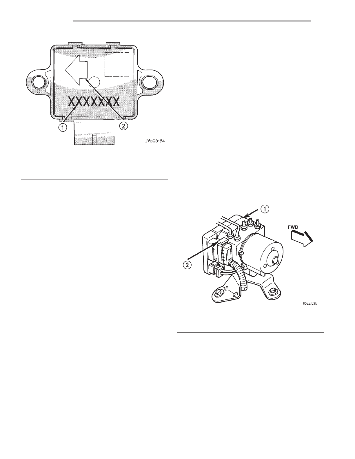
5 - 36 BRAKES XJ
DESCRIPTION AND OPERATION (Continued)
(3) Select ANTILOCK BRAKES, followed by MISCELLANEOUS, then ABS BRAKES. Follow the
instructions displayed. When scan tool displays TEST
COMPLETE, disconnect scan tool and proceed.
(4) Perform base brake bleeding a second time.
Refer to base brake section for procedure.
(5) Top off master cylinder fluid level and verify
proper brake operation before moving vehicle.
REMOVAL AND INSTALLATION
HYDRAULIC CONTROL UNIT/CONTROLLER ANTILOCK BRAKES
REMOVAL
Fig. 3 G-Switch
1 – SWITCH PART NUMBER
2 – ARROW INDICATES FRONT OF SWITCH FOR PROPER
MOUNTING
DIAGNOSIS AND TESTING
(1) Remove negative battery cable from the battery.
(2) Pull up on the CAB harness connector release
(Fig. 4) and remove connector.
(3) Remove brake lines from the HCU.
(4) Remove HCU/CAB mounting nuts and bolt
(Fig. 5) and remove HCU/CAB.
ANTILOCK BRAKES
The ABS brake system performs several self-tests
every time the ignition switch is turned on and the
vehicle is driven. The CAB monitors the systems
input and output circuits to verify the system is operating correctly. If the on board diagnostic system
senses that a circuit is malfunctioning the system
will set a trouble code in its memory.
NOTE: An audible noise may be heard during the
self-test. This noise should be considered normal.
NOTE: The MDS or DRB III scan tool is used to
diagnose the ABS system. For additional information refer to the Antilock Brake section in Group
8W. For test procedures refer to the Chassis Diagnostic Manual.
SERVICE PROCEDURES
BLEEDING ABS BRAKE SYSTEM
ABS system bleeding requires conventional bleeding methods plus use of the DRB scan tool. The procedure involves performing a base brake bleeding,
followed by use of the scan tool to cycle and bleed the
HCU pump and solenoids. A second base brake bleeding procedure is then required to remove any air
remaining in the system.
(1) Perform base brake bleeding. Refer to base
brake section for procedure.
(2) Connect scan tool to the Data Link Connector.
Fig. 4 CAB Harness Connector Release
1 – CAB
2 – CAB HARNESS RELEASE
INSTALLATION
(1) Install HCU/CAB on the mounting studs.
(2) Install mounting nuts and bolt. Tighten to 11.5
N·m (102 in. lbs.).
(3) Install brake lines to the HCU and tighten to
19 N·m (170 in. lbs.).
(4) Install wiring harness connector to the CAB
and push down on the release to secure the connector.
(5) Install negative battery cable to the battery.
(6) Bleed ABS brake system.
Page 37
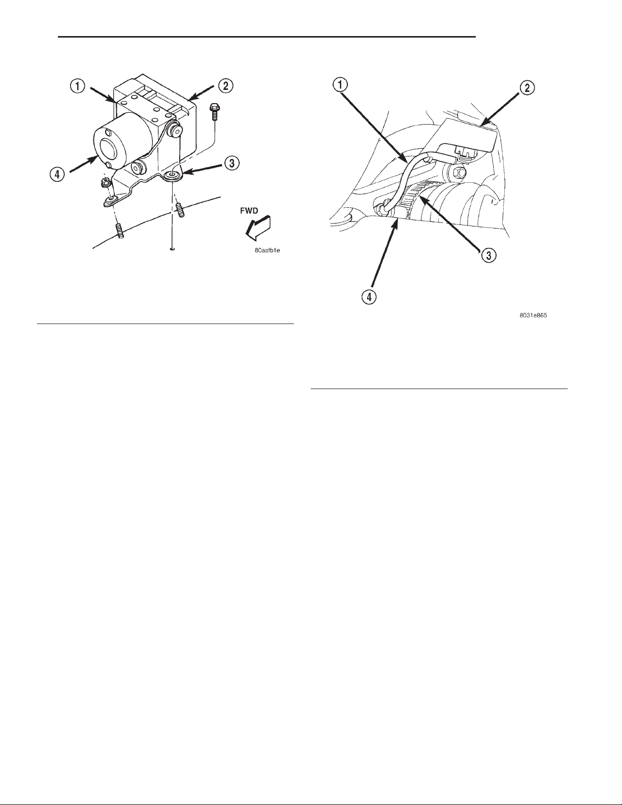
XJ BRAKES 5 - 37
REMOVAL AND INSTALLATION (Continued)
Fig. 5 HCU/CAB Mounting
1 – HCU
2 – CAB
3 – HCU/CAB BRACKET
4 – MOTOR
FRONT WHEEL SPEED SENSOR
REMOVAL
(1) Raise vehicle and turn wheel outward for eas-
ier access to sensor.
(2) Remove sensor wire from mounting brackets.
(3) Clean sensor and surrounding area with shop
towel before removal.
(4) Remove bolt attaching sensor to steering
knuckle and remove sensor (Fig. 6).
(5) Remove sensor wire from brackets on body and
steering knuckle.
(6) Unseat sensor wire grommet in wheel house
panel.
(7) In engine compartment, disconnect sensor wire
connector at harness plug. Then remove sensor and
wire.
INSTALLATION
(1) If original sensor will be installed, wipe all
traces of old spacer material off sensor pickup face.
Use a dry shop towel for this purpose.
(2) Apply Mopar Lock N’ Seal or Loctite t 242 to
bolt that secures sensor in steering knuckle. Use new
sensor bolt if original bolt is worn or damaged.
(3) Position sensor on steering knuckle. Seat sensor locating tab in hole in knuckle and install sensor
attaching bolt finger tight.
(4) Tighten sensor attaching bolt to 4.7 N·m (42 in.
lbs.).
(5) If original sensor has been installed, check sensor air gap. Air gap should be 0.36 to 1.5 mm (0.014
to 0.059 in.). If gap is incorrect, sensor is either loose,
or damaged.
Fig. 6 Front Wheel Speed Sensor
1 – WHEEL SPEED SENSOR PIGTAIL
2 – STEERING KNUCKLE
3 – TONE WHEEL
4 – FRONT WHEEL SPEED SENSOR
(6) Secure sensor wire to steering knuckle and
body brackets.
(7) Route sensor wire forward and behind shock
absorber. Then attach sensor wire to spring seat
bracket with grommets on sensor wire.
(8) Route sensor wire to outer sill bracket. Remove
all twists or kinks from wire.
(9) Attach sensor wire to sill bracket with grommet. Be sure wire is free of twists and kinks.
(10) Verify sensor wire routing. Wire should loop
forward and above sill bracket. Loose end of wire
should be below sill bracket and towards brake hose.
(11) Seat sensor wire grommet in body panel and
clip wire to brake line at grommet location.
(12) Connect sensor wire to harness in engine compartment.
REAR WHEEL SPEED SENSOR
REMOVAL
(1) Raise and fold rear seat forward for access to
rear sensor connectors (Fig. 7).
(2) Disconnect sensors at rear harness connectors.
(3) Push sensor grommets and sensor wires
through floorpan.
(4) Raise vehicle.
(5) Disconnect sensor wires at rear axle connectors.
(6) Remove wheel and tire assembly.
Page 38
5 - 38 BRAKES XJ
REMOVAL AND INSTALLATION (Continued)
Fig. 8 Rear Wheel Speed Sensor
1 – TONE WHEEL
2 – WHEEL SPEED SENSOR
Fig. 7 Acceleration Switch And Rear Sensor
Connections
1 – REAR SEAT CROSSMEMBER
2 – ACCELERATION SENSOR
3 – SENSOR MOUNTING BRACKET
4 – TO R. R. WHEEL SENSOR
5 – TO L. R. WHEEL SENSOR
6 – FLOORPAN
7 – SENSOR HARNESS
(7) Remove brake drum.
(8) Remove clips securing sensor wires to brake
lines, rear axle and, brake hose.
(9) Unseat sensor wire support plate grommet.
(10) Remove bolt attaching sensor to bracket and
remove sensor (Fig. 8).
INSTALLATION
(1) If original sensor is being installed, remove
any remaining pieces of cardboard spacer from sensor pickup face. Use dry shop towel only to remove
old spacer material.
(2) Insert sensor wire through support plate hole.
Then seat sensor grommet in support plate.
(3) Apply Mopar Lock N’ Seal or Loctite t 242 to
original sensor bolt. Use new bolt if original is worn
or damaged.
(4) Install sensor bolt finger tight only at this
time.
(5) If original rear sensor was installed, adjust
sensor air gap to 0.92-1.275 mm (0.036-0.05 in.). Use
feeler gauge to measure air gap (Fig. 9). Tighten sensor bolt to 13 N·m (115 in. lbs.).
(6) If new sensor was installed, push cardboard
spacer on sensor face against tone ring (Fig. 10).
Fig. 9 Setting Air Gap On Original Rear Sensor
1 – WHEEL SPEED SENSOR
2 – BRASS FEELER GAUGE
3 – TONE RING
Then tighten sensor bolt to 13 N·m (115 in. lbs.). Correct air gap will be established as tone ring rotates
and peels spacer off sensor face.
(7) Route sensor wires to rear seat area.
(8) Feed sensor wires through floorpan access hole
and seat sensor grommets in floorpan.
(9) Verify that rear sensor wires are secured to
rear brake hose and axle with clips. Verify that wire
is clear of rotating components.
(10) Install brake drum and wheel and tire assembly.
(11) Lower vehicle.
(12) Connect sensor wire to harness connector.
Then reposition carpet and fold rear seat down.
G-SWITCH
REMOVAL
(1) Raise and fold rear seat assembly forward for
access to sensor.
Page 39
XJ BRAKES 5 - 39
REMOVAL AND INSTALLATION (Continued)
Fig. 10 New Rear Sensor
1 – REAR SENSOR
2 – AIR GAP SPACERATTACHED TO SENSOR FACE
(2) Disconnect switch harness.
(3) Remove switch mounting screws (Fig. 11)
(4) Remove the acceleration switch.
Fig. 11 G-Switch Mounting
1 – ACCELERATION SWITCH
2 – SWITCH BRACKET
3 – REAR SEAT CROSSMEMBER
Fig. 12 G-Switch
1 – SWITCH PART NUMBER
2 – ARROW INDICATES FRONT OF SWITCH FOR PROPER
MOUNTING
(3) Connect harness to switch. Be sure harness
connector is firmly seated.
(4) Move seat back to normal position.
DISASSEMBLY AND ASSEMBLY
HYDRAULIC CONTROL UNIT/CONTROLLER ANTILOCK BRAKE
DISASSEMBLY
(1) Remove pump motor connector from the CAB.
(2) Remove CAB mounting screws from the HCU
(Fig. 13).
(3) Remove CAB from the HCU.
INSTALLATION
CAUTION: The mercury switch (inside the
G-switch), will not function properly if the switch is
installed incorrectly. Verify that the switch locating
arrow is pointing to the front of the vehicle (Fig.
12).
(1) Position switch in mounting bracket.
(2) Install switch mounting bolts and tighten to 3
N·m (27.5 in. lbs.).
Fig. 13 CAB Mounting Screws
1 – MOUNTING SCREWS
2 – CAB
Page 40

5 - 40 BRAKES XJ
DISASSEMBLY AND ASSEMBLY (Continued)
ASSEMBLY
(1) Install the CAB onto the HCU.
(2) Install the CAB mounting screws and tighten
to 1.8 N·m (16 in. lbs.).
(3) Install pump motor connector to the CAB.
SPECIFICATIONS
T0RQUE CHART
DESCRIPTION TORQUE
G-Sensor
Sensor Bolt .............. 3N·m(27.5 in. lbs.)
Bracket Bolt ............. 2.7N·m(24in.lbs.)
Hydraulic Control Unit/Controller Antilock
Brakes
Mounting Nuts ......... 11.5N·m(102 in. lbs.)
Brake Lines ............. 19N·m(170 in. lbs.)
Controller Antilock Brakes
Mounting Screws ......... 1.8N·m(16in.lbs.)
Wheel Speed Sensors
Front Mounting Bolt ...... 4.7N·m(42in.lbs.)
Rear Mounting Bolt ....... 13N·m(115in.lbs.)
 Loading...