

Page 1
XJ DIFFERENTIAL AND DRIVELINE 3 - 1
DIFFERENTIAL AND DRIVELINE
TABLE OF CONTENTS
page page
PROPELLER SHAFTS ....................... 1
TUBE, 181, AND 186 FBI AXLE.............. 16
PROPELLER SHAFTS
TABLE OF CONTENTS
page page
DESCRIPTION AND OPERATION
PROPELLER SHAFT .......................1
PROPELLER SHAFT JOINTS.................2
PROPELLER SHAFT JOINT ANGLE............3
DIAGNOSIS AND TESTING
VIBRATION ..............................4
UNBALANCE .............................5
RUNOUT ................................5
SERVICE PROCEDURES
DRIVELINE ANGLE MEASUREMENT
PREPARATION..........................6
PROPELLER SHAFT ANGLE MEASUREMENT....6
REMOVAL AND INSTALLATION
FRONT PROPELLER SHAFT.................8
194 RBI AXLE............................ 65
8 1/4 REAR AXLE........................ 103
REAR PROPELLER SHAFT ..................8
DISASSEMBLY AND ASSEMBLY
SINGLE CARDAN UNIVERSAL JOINT ..........9
DOUBLE CARDAN JOINT...................11
CLEANING AND INSPECTION
PROPELLER SHAFT ......................14
ADJUSTMENTS
REAR AXLE PINION INPUT ANGLE ...........15
FRONT AXLE PINION INPUT ANGLE ..........15
SPECIFICATIONS
PROPELLER SHAFTS AND U–JOINTS.........15
SPECIAL TOOLS
PROPELLER SHAFT ......................15
DESCRIPTION AND OPERATION
PROPELLER SHAFT
DESCRIPTION
A propeller shaft (Fig. 2) is the shaft which connects the transmission/transfer case to the axle differential. This is the link through which the engine
power is transmitted to the axle.
The propeller shaft is designed and built with the
yoke lugs in line with each other which is called zero
phasing. This design produces the smoothest running
condition, an out-of-phase shaft can cause a vibration.
Tubular propeller shafts are balanced by the manufacturer with weights spot welded to the tube.
PRECAUTIONS
Use the exact replacement parts when installing
the propeller shafts. The use of the correct replace-
ment parts helps to ensure safe operation. All fasteners must be torqued to the specified values for safe
operation.
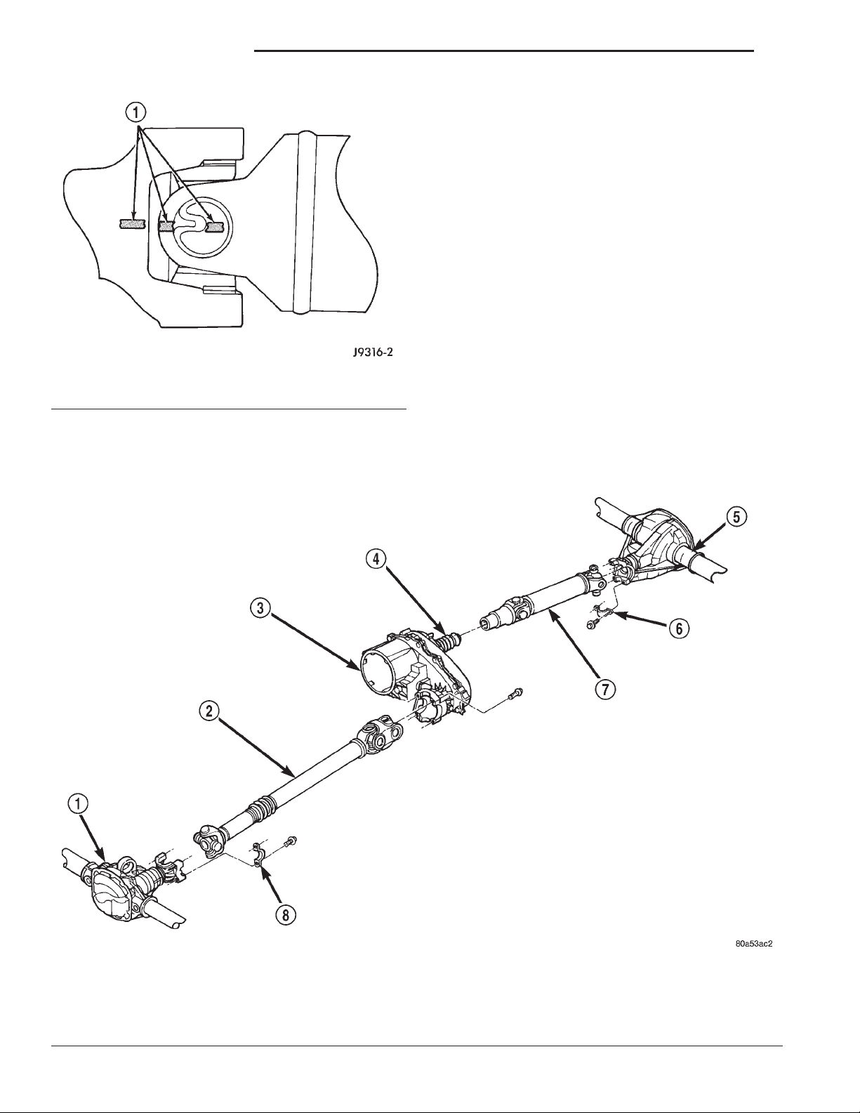
Also make alignment reference marks (Fig. 1) on
the propeller shaft yoke and axle, or transmission,
yoke prior to servicing. This helps to eliminate possible vibration.
CAUTION: Do not allow the propeller shaft to drop
or hang from any propeller shaft joint during
removal. Attach the propeller shaft to the vehicle
underside with wire to prevent damage to the joints.
OPERATION
The propeller shaft must operate through constantly changing relative angles between the transmission and axle when going over various road
surfaces. It must also be capable of changing length
while transmitting torque. The axle rides suspended
by springs in a floating motion.This is accomplished
through universal joints, which permit the propeller
Page 2
3 - 2 PROPELLER SHAFTS XJ
DESCRIPTION AND OPERATION (Continued)
Before undercoating a vehicle, the propeller
shaft and the U-joints should be covered to prevent an out-of-balance condition and driveline
vibration.
CAUTION: Use original equipment replacement
parts for attaching the propeller shafts. The specified torque must always be applied when tightening
the fasteners.
PROPELLER SHAFT JOINTS
DESCRIPTION
Two different types of propeller shaft joints are
used:
Fig. 1 Reference Marks on Yokes
1 – REFERENCE MARKS
shaft to operate at different angles. The slip joints (or
yokes) permit contraction or expansion (Fig. 2).
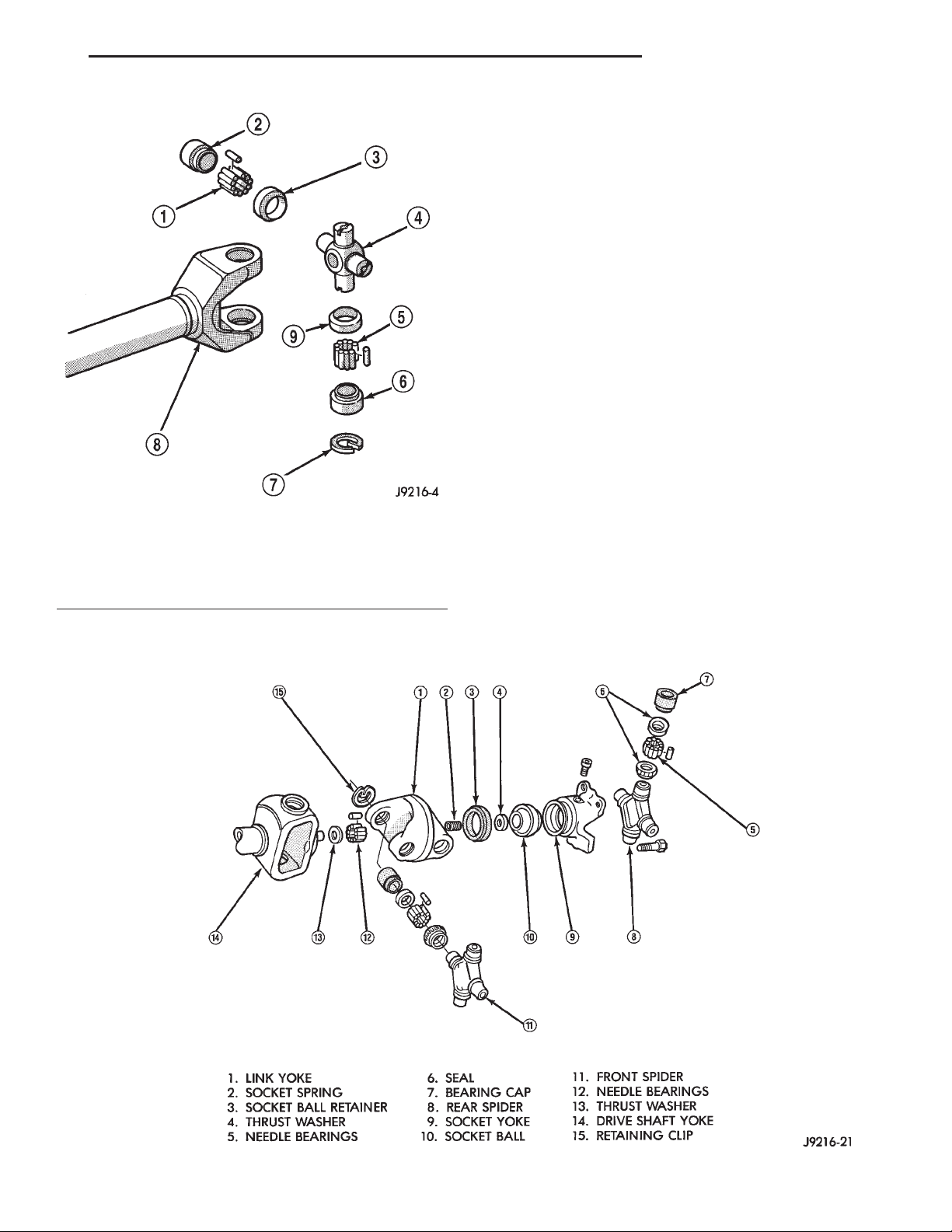
• Single cardan universal joint (Fig. 3)
• Double cardan (CV) universal joint (Fig. 4)
None of the universal joints are serviceable. If one
becomes worn or damaged, the complete universal
joint assembly must be replaced.
1 – FRONT AXLE
2 – FRONT PROPELLER SHAFT
3 – TRANSFER CASE
4 – BOOT
Fig. 2 Propeller Shafts
5 – REAR AXLE
6 – STRAP
7 – REAR PROPELLER SHAFT
8 – STRAP
Page 3
XJ PROPELLER SHAFTS 3 - 3
DESCRIPTION AND OPERATION (Continued)
PROPELLER SHAFT JOINT ANGLE
DESCRIPTION
When two shafts come together at a common joint,
the bend that is formed is called the operating angle.
The larger the angle, the larger the amount of angular acceleration and deceleration of the joint. This
speeding up and slowing down of the joint must be
cancelled to produce a smooth power flow.
OPERATION
This cancellation is done through the phasing of a
propeller shaft and ensuring that the proper propeller shaft joint working angles are maintained.
A propeller shaft is properly phased when the yoke
ends are in the same plane, or in line. A twisted
shaft will make the yokes out of phase and cause a
noticeable vibration.
When taking propeller shaft joint angle measurements, or checking the phasing, of two piece shafts,
Fig. 3 Single Cardan Universal Joint
1 – NEEDLE BEARING 6 – BEARING CAP
2 – BEARING CAP 7 – RETAINING CLIP
3 – SEAL 8 – YOKE
4 – SPIDER 9 – SEAL
5 – NEEDLE BEARING
consider each shaft separately.
Ideally the driveline system should have;
• Angles that are equal or opposite within 1
degree of each other.
• Have a 3 degree maximum operating angle.
• Have at least a 1/2 degree continuous operating
(propeller shaft) angle.
Fig. 4 Double Cardan (CV) Universal Joint
Page 4
3 - 4 PROPELLER SHAFTS XJ
DESCRIPTION AND OPERATION (Continued)
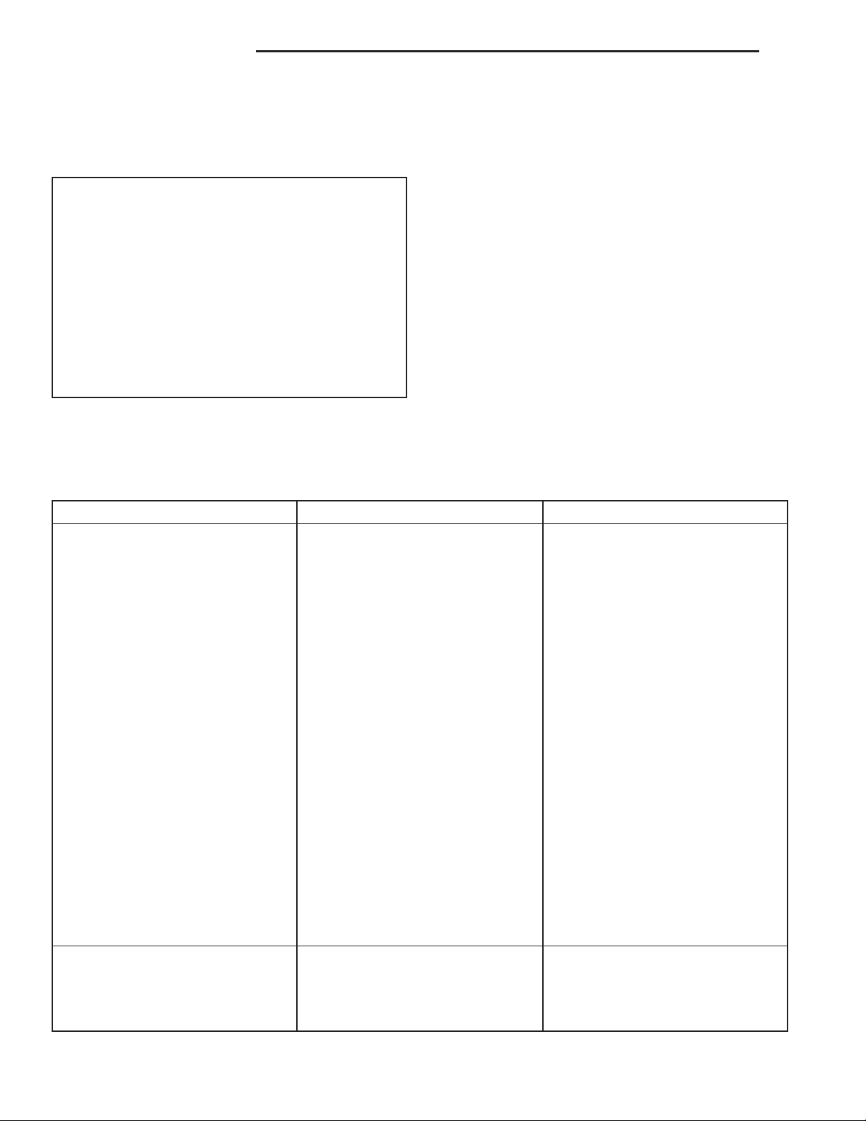
Propeller shaft speed (rpm) is the main factor in
determining the maximum allowable operating angle.
As a guide to the maximum normal operating angles
refer to (Fig. 5).
PROPELLER SHAFT MAX. NORMAL
R.P.M. OPERATING ANGLES
5000 3°
4500 3°
4000 4°
3500 5°
3000 5°
2500 7°
2000 8°
1500 11°
Fig. 5 Maximum Angles And Propeller Shaft Speed
DRIVELINE VIBRATION
Drive Condition Possible Cause Correction
DIAGNOSIS AND TESTING
VIBRATION
Tires that are out-of-round, or wheels that are
unbalanced, will cause a low frequency vibration.
Refer to Group 22, Tires and Wheels, for additional
information.
Brake drums that are unbalanced will cause a
harsh, low frequency vibration. Refer to Group 5,
Brakes, for additional information.
Driveline vibration can also result from loose or
damaged engine mounts. Refer to Group 9, Engines,
for additional information.
Propeller shaft vibration increases as the vehicle
speed is increased. A vibration that occurs within a
specific speed range is not usually caused by a propeller shaft being unbalanced. Defective universal
joints, or an incorrect propeller shaft angle, are usually the cause of such a vibration.
Propeller Shaft Noise 1) Undercoating or other foreign
material on shaft.
2) Loose U-joint clamp screws. 2) Install new clamps and screws
3) Loose or bent U-joint yoke or
excessive runout.
4) Incorrect driveline angularity. 4) Measure and correct driveline
5) Rear spring center bolt not in
seat.
6) Worn U-joint bearings. 6) Install new U-joint.
7) Propeller shaft damaged or out
of balance.
8) Broken rear spring. 8) Install new rear spring.
9) Excessive runout or unbalanced
condition.
10) Excessive drive pinion gear
shaft runout.
11) Excessive axle yoke deflection. 11) Inspect and replace yoke if
12) Excessive transfer case runout. 12) Inspect and repair as necessary.
1) Clean exterior of shaft and wash
with solvent.
and tighten to proper torque.
3) Install new yoke.
angles.
5) Loosen spring u-bolts and seat
center bolt.
7) Installl new propeller shaft.
9) Re-index propeller shaft, test,
and evaluate.
10) Re-index propeller shaft and
evaluate.
necessary.
Universal Joint Noise 1) Loose U-joint clamp screws. 1) Install new clamps and screws
and tighten to proper torque.
2) Lack of lubrication. 2) Replace as U-joints as
necessary.
Page 5
XJ PROPELLER SHAFTS 3 - 5
DIAGNOSIS AND TESTING (Continued)
UNBALANCE
NOTE: Removing and re-indexing the propeller
shaft 180° relative to the yoke may eliminate some
vibrations.
If propeller shaft is suspected of being unbalanced,
it can be verified with the following procedure:
(1) Raise the vehicle.
(2) Clean all the foreign material from the propel-
ler shaft and the universal joints.
(3) Inspect the propeller shaft for missing balance
weights, broken welds, and bent areas. If the pro-
peller shaft is bent, it must be replaced.
(4) Inspect the universal joints to ensure that they
are not worn, are properly installed, and are correctly aligned with the shaft.
(5) Check the universal joint clamp screws torque.
(6) Remove the wheels and tires. Install the wheel
lug nuts to retain the brake drums or rotors.
(7) Mark and number the shaft six inches from the
yoke end at four positions 90° apart.
(8) Run and accelerate the vehicle until vibration
occurs. Note the intensity and speed the vibration
occurred. Stop the engine.
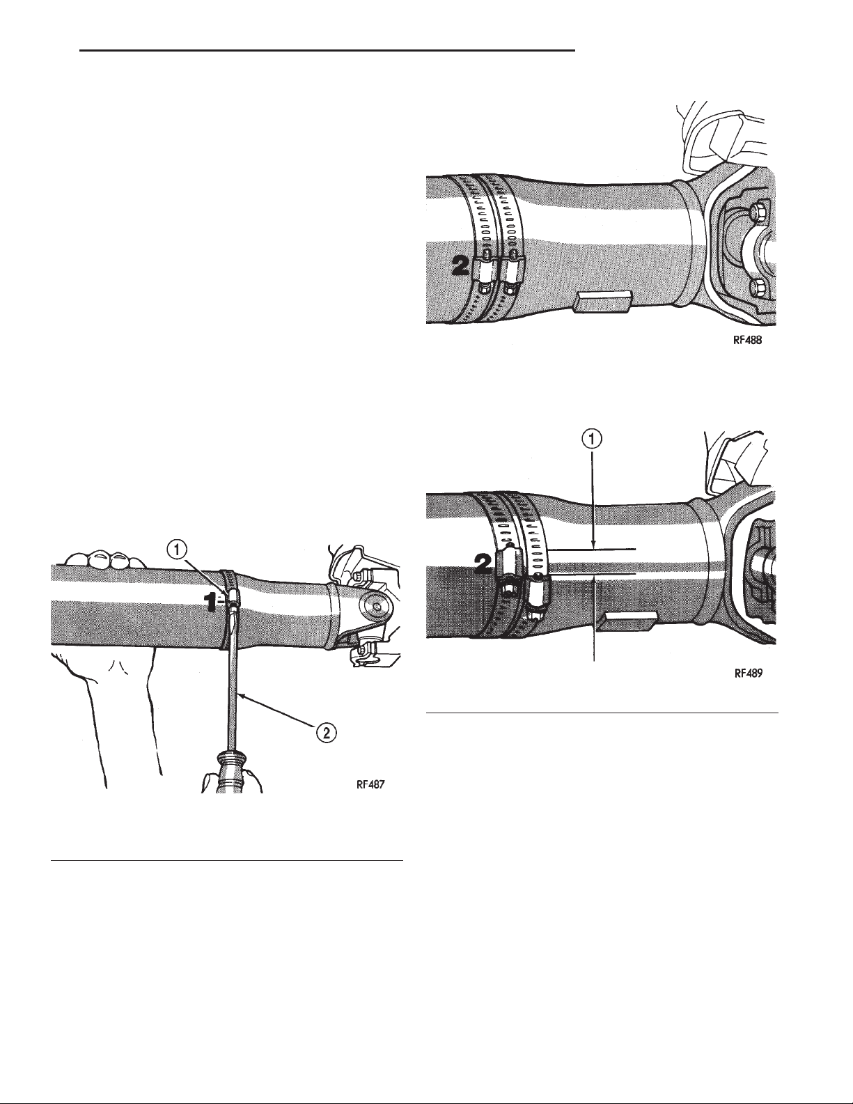
(9) Install a screw clamp at position 1 (Fig. 6).
Fig. 7 Two Clamp Screws At The Same Position
(13) If the additional clamp causes an additional
vibration, separate the clamps (1/4 inch above and
below the mark). Repeat the vibration test (Fig. 8).
Fig. 6 Clamp Screw At Position 1
1 – CLAMP
2 – SCREWDRIVER
(10) Start the engine and re-check for vibration. If
there is little or no change in vibration, move the
clamp to one of the other three positions. Repeat the
vibration test.
(11) If there is no difference in vibration at the
other positions, the source of the vibration may not
be propeller shaft.
(12) If the vibration decreased, install a second
clamp (Fig. 7) and repeat the test.
Fig. 8 Clamp Screws Separated
1–1⁄2INCH
(14) Increase distance between the clamp screws
and repeat the test until the amount of vibration is
at the lowest level. Bend the slack end of the clamps
so the screws will not loosen.
(15) If the vibration remains unacceptable, apply
the same steps to the front end of the propeller shaft.
(16) Install the wheel and tires. Lower the vehicle.
RUNOUT
(1) Remove dirt, rust, paint, and undercoating
from the propeller shaft surface where the dial indicator will contact the shaft.
(2) The dial indicator must be installed perpendicular to the shaft surface.
(3) Measure runout at the center and ends of the
shaft sufficiently far away from weld areas to ensure
that the effects of the weld process will not enter into
the measurements.
Page 6
3 - 6 PROPELLER SHAFTS XJ
DIAGNOSIS AND TESTING (Continued)
(4) Refer to Runout Specifications chart.
(5) If the propeller shaft runout is out of specification, remove the propeller shaft, index the shaft 180°,
and re-install the propeller shaft. Measure shaft
runout again.
(6) If the propeller shaft runout is now within
specifications, mark the shaft and yokes for proper
orientation.
(7) If the propeller shaft runout is not within specifications, verify that the runout of the transmission/
transfer case and axle are within specifications.
Correct as necessary and re-measure propeller shaft
runout.
(8) Replace the propeller shaft if the runout still
exceeds the limits.
RUNOUT SPECIFICATIONS
Front of Shaft 0.020 in. (0.50 mm)
Center of Shaft 0.025 in. (0.63 mm)
Rear of Shaft 0.020 in. (0.50 mm)
Measure front/rear runout approximately 3 inches
(76 mm) from the weld seam at each end of the shaft
tube for tube lengths over 30 inches. For tube lengths
under 30 inches, the maximum allowed runout is
0.020 in. (0.50 mm) for the full length of the tube.
(2) Rotate the shaft until transmission/transfer
case output yoke bearing is facing downward.
Always make measurements from front to
rear. Also, be sure to take all measurements
while working from the same side of the vehicle.
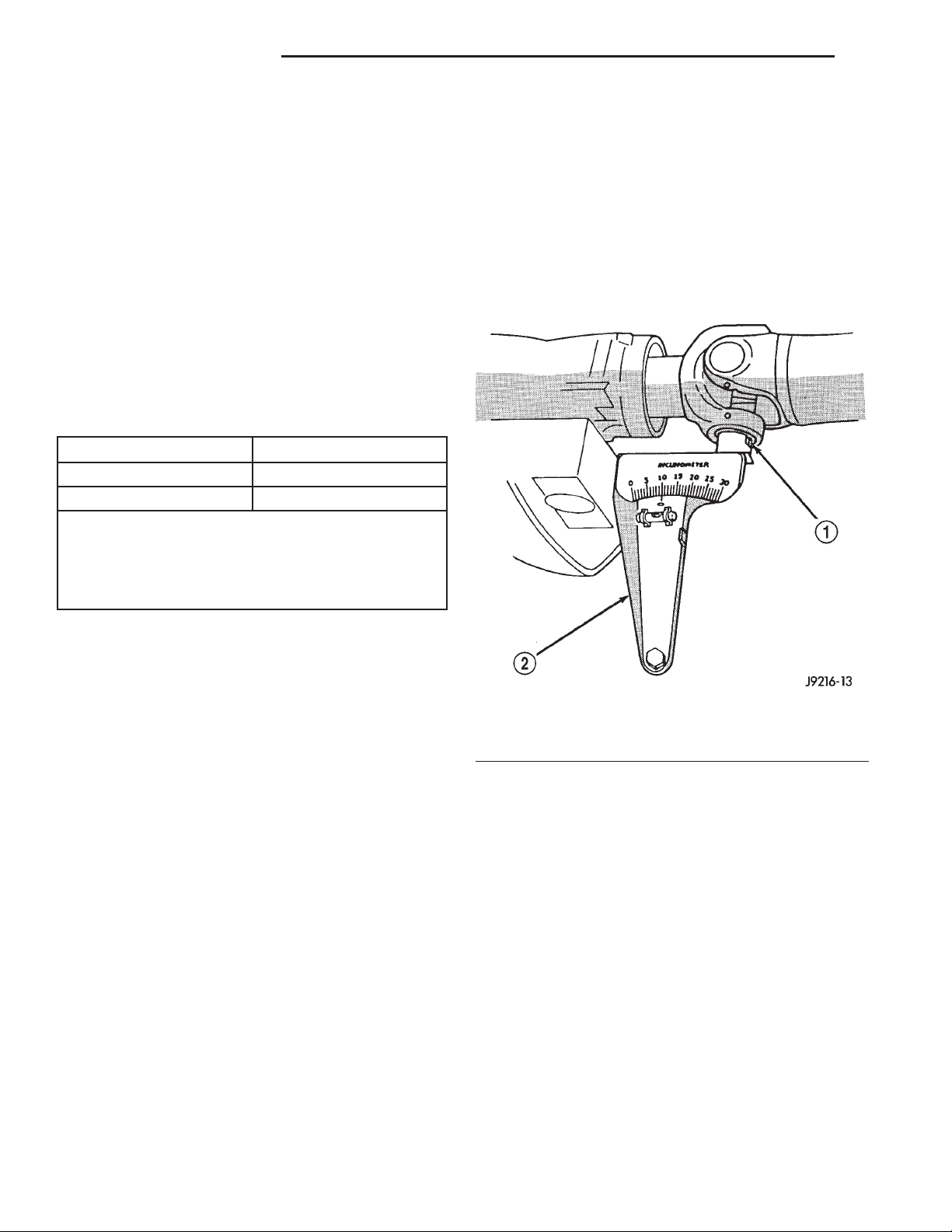
(3) Place Inclinometer on yoke bearing (A) parallel
to the shaft (Fig. 9). Center bubble in sight glass and
record measurement.
This measurement will give you the transmission or Output Yoke Angle (A).
SERVICE PROCEDURES
DRIVELINE ANGLE MEASUREMENT PREPARATION
Before measuring universal joint angles, the fol-
lowing must be done;
• Inflate all tires to correct pressure.
• Check the angles in the same loaded or
unloaded condition as when the vibration occurred.
Propeller shaft angles change according to the
amount of load in the vehicle.
• Check the condition of all suspension components and verify all fasteners are torqued to specifications.
• Check the condition of the engine and transmission mounts and verify all fasteners are torqued to
specifications.
PROPELLER SHAFT ANGLE MEASUREMENT
To accurately check driveline alignment, raise and
support the vehicle at the axles as level as possible.
Allow the wheels and propeller shaft to turn.
(1) Remove any external bearing snap rings, if
equipped, from universal joint so protractor base sits
flat.
Fig. 9 Front (Output) Angle Measurement (A)
1 – SLIP YOKE BEARING CAP
2 – SPECIAL TOOL 7663 (J-23498A)
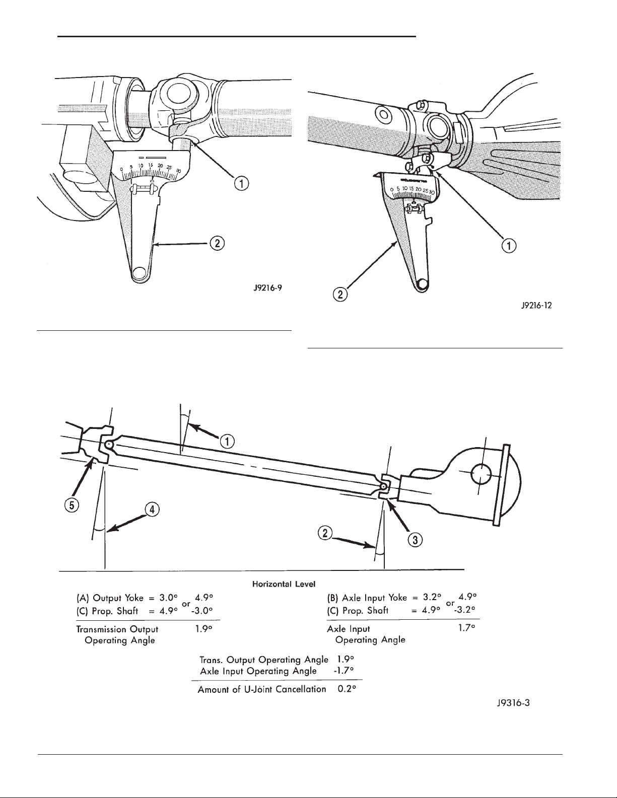
(4) Rotate propeller shaft 90 degrees and place
Inclinometer on yoke bearing parallel to the shaft
(Fig. 10). Center bubble in sight glass and record
measurement. This measurement can also be taken
at the rear end of the shaft.
This measurement will give you the Propeller
Shaft Angle (C).
(5) Subtract smaller figure from larger (C minus
A) to obtain Transmission Output Operating Angle.
(6) Rotate propeller shaft 90 degrees and place
Inclinometer on pinion yoke bearing parallel to the
shaft (Fig. 11). Center bubble in sight glass and
record measurement.
Page 7
XJ PROPELLER SHAFTS 3 - 7
SERVICE PROCEDURES (Continued)
Fig. 10 Propeller Shaft Angle Measurement (C)
1 – SHAFT YOKE BEARING CAP
2 – SPECIAL TOOL 7663 (J23498–A)
This measurement will give you the pinion
shaft or Input Yoke Angle (B).
(7) Subtract smaller figure from larger (C minus
B) to obtain axle Input Operating Angle.
Fig. 11 Rear (Input) Angle Measurement (B)
1 – PINION YOKE BEARING CAP
2 – SPECIAL TOOL 7663 (J-23498A)
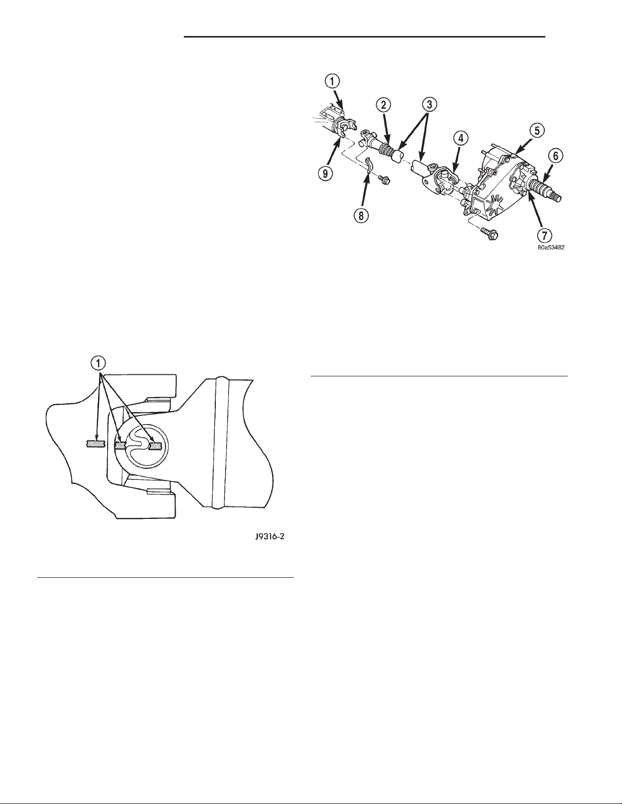
Refer to rules given below and the example in
(Fig. 12) for additional information.
1 – 4.9° Angle (C)
2 – 3.2° Angle (B)
3 – Input Yoke
Fig. 12 Universal Joint Angle Example
4 – 3.0° Angle (A)
5 – Output Yoke
Page 8
3 - 8 PROPELLER SHAFTS XJ
SERVICE PROCEDURES (Continued)
• Good cancellation of U–joint operating angles
(within 1°).
• Operating angles less than 3°.
• At least 1/2 of one degree continuous operating
(propeller shaft) angle.
REMOVAL AND INSTALLATION
FRONT PROPELLER SHAFT
REMOVAL
(1) Hoist and support vehicle on safety stands.
(2) Remove the crossmember/skid plate as neces-
sary to gain access to the propeller shaft.
(3) Shift the transmission and transfer case, if nec-
essary, into the Neutral position.
(4) Using a suitable marker, mark a line across
the yoke at the transfer case, the link yoke, and propeller shaft yoke at the rear of the front propeller
shaft for installation reference (Fig. 13).
(5) Mark a line across the propeller shaft yoke and
the pinion shaft yoke for installation reference.
1 – FRONT AXLE
2 – BOOT
3 – PROPELLER SHAFT
4 – CV-JOINT
5 – TRANSFER CASE
6 – BOOT
7 – SLINGER
8 – CLAMP
9 – YOKE
Fig. 14 Front Propeller Shaft
Fig. 13 Reference Marks on Yokes
1 – REFERENCE MARKS
(6) Remove the U-joint strap bolts at the pinion
shaft yoke (Fig. 14).
(7) Remove bolts holding rear universal joint to
the transfer case yoke.
(8) Separate the rear universal joint from the
transfer case yoke.
(9) Push rear of propeller shaft upward to clear
transfer case yoke.
(10) Separate front universal joint from front axle.
(11) Separate propeller shaft from vehicle.
INSTALLATION
(1) Position front propeller shaft under vehicle
with rear universal joint over the transfer case yoke.
(2) Place front universal joint into the axle pinion
yoke.
(3) Align mark on the rear link yoke and universal
joint to the mark on the transfer case yoke (Fig. 13).
(4) Loosely install bolts to hold universal joint to
transfer case yoke.
(5) Align mark on front universal joint to the mark
on the axle pinion yoke.
(6) Tighten the U-joint strap/clamp bolts at the
axle yoke to 19 N·m (14 ft. lbs.) torque.
(7) Tighten the universal joint to transfer case
bolts to 27 N·m (20 ft. lbs.) torque.
(8) Lower the vehicle.
REAR PROPELLER SHAFT
REMOVAL
(1) Shift the transmission and transfer case into
Neutral.
(2) Hoist and support vehicle on safety stands.
(3) Scribe alignment marks at the pinion shaft and
at each end of the propeller shaft. These marks will
be used for installation reference.
(4) Remove the U-joint strap bolts at the pinion
shaft yoke.
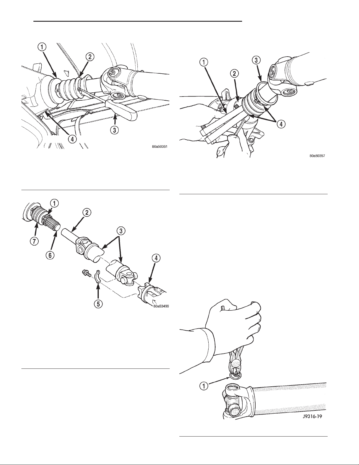
(5) Pry open clamp holding the dust boot to propeller shaft yoke (Fig. 15).
(6) Slide the slip yoke off of the transmission/
transfer case output shaft and remove the propeller
shaft (Fig. 16).
Page 9
XJ PROPELLER SHAFTS 3 - 9
REMOVAL AND INSTALLATION (Continued)
(4) Lower the vehicle.
Fig. 15 Dust Boot Clamp
1 – SLINGER
2 – BOOT
3–AWL
4 – TRANSFER CASE
Fig. 16 Rear Propeller Shaft
1 – CLAMP
2 – YOKE
3 – PROPELLER SHAFT
4 – AXLE YOKE
5 – CLAMP
6 – OUTPUT SHAFT
7 – BOOT
Fig. 17 Crimping Dust Boot Clamp
1 – SPECIAL TOOL C-4975–A
2 – SLINGER
3 – BOOT
4 – CLAMP
DISASSEMBLY AND ASSEMBLY
SINGLE CARDAN UNIVERSAL JOINT
DISASSEMBLY
Individual components of cardan universal joints
are not serviceable. If worn or leaking, they must be
replaced as an assembly.
(1) Remove the propeller shaft.
(2) Using a soft drift, tap the outside of the bearing cap assembly to loosen snap ring.
(3) Remove snap rings from both sides of yoke
(Fig. 18).
INSTALLATION
(1) Slide the slip yoke on the transmission/transfer
case output shaft. Align the installation reference
marks at the axle yoke and install the propeller shaft
(Fig. 16).
(2) Tighten the U-joint strap/clamp bolts at the
axle yoke to 19 N·m (14 ft. lbs.) torque.
(3) Crimp clamp to hold dust boot to propeller
shaft yoke (Fig. 17).
Fig. 18 Remove Snap Ring
1 – SNAP RING
Page 10
3 - 10 PROPELLER SHAFTS XJ
DISASSEMBLY AND ASSEMBLY (Continued)
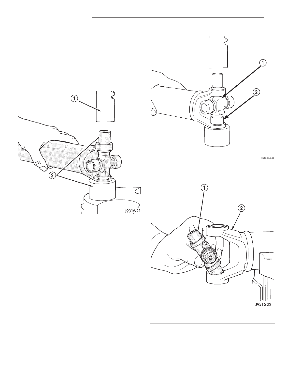
(4) Set the yoke in an arbor press or vise with a
socket whose inside diameter is large enough to
receive the bearing cap positioned beneath the yoke.
(5) Position the yoke with the grease fitting, if
equipped, pointing up.
(6) Place a socket with an outside diameter
smaller than the upper bearing cap on the upper
bearing cap and press the cap through the yoke to
release the lower bearing cap (Fig. 19).
Fig. 19 Press Out Bearing
1 – PRESS
2 – SOCKET
(7) If the bearing cap will not pull out of the yoke
by hand after pressing, tap the yoke ear near the
bearing cap to dislodge the cap.
(8) To remove the opposite bearing cap, turn the
yoke over and straighten the cross in the open hole.
Then, carefully press the end of the cross until the
remaining bearing cap can be removed (Fig. 20).
CAUTION: If the cross or bearing cap are not
straight during installation, the bearing cap will
score the walls of the yoke bore and damage can
occur.
Fig. 20 Press Out Remaining Bearing
1 – CROSS
2 – BEARING CAP
Fig. 21 Install Cross In Yoke
1 – CROSS
2 – YOKE
ASSEMBLY
(1) Apply extreme pressure (EP) N.L.G.I. Grade 1
or 2 grease to inside of yoke bores to aid in installation.
(2) Position the cross in the yoke with its lube fitting, if equipped, pointing up (Fig. 21).
(3) Place a bearing cap over the trunnion and
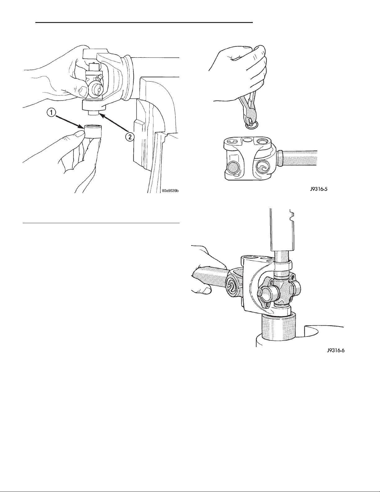
align the cap with the yoke bore (Fig. 22). Keep the
needle bearings upright in the bearing assembly. A
needle bearing lying at the bottom of the cap will
prevent proper assembly.
Page 11
XJ PROPELLER SHAFTS 3 - 11
DISASSEMBLY AND ASSEMBLY (Continued)
Fig. 22 Install Bearing On Trunnion
1 – BEARING CAP
2 – TRUNNION
(4) Press the bearing cap into the yoke bore
enough to install a snap ring.
(5) Install a snap ring.
(6) Repeat Step 3 and Step 4to install the opposite
bearing cap. If the joint is stiff or binding, strike the
yoke with a soft hammer to seat the needle bearings.
(7) Add grease to lube fitting, if equipped.
(8) Install the propeller shaft.
DOUBLE CARDAN JOINT
DISASSEMBLY
Individual components of cardan universal joints
are not serviceable. If worn or leaking, they must be
replaced as an assembly.
(1) Remove the propeller shaft.
(2) Using a soft drift, tap the outside of the bearing cap assembly to loosen snap ring.
Remove all the bearing cap snap rings (Fig. 23).
(3)
(4) Set the joint in an arbor press or vise with a
socket whose inside diameter is large enough to
receive the bearing cap positioned beneath the link
yoke.
(5) Place a socket with an outside diameter
smaller than the upper bearing cap on the upper
bearing cap and partially press one bearing cap from
the outboard side of the link yoke enough to grasp
the bearing cap with vise jaws (Fig. 24). Be sure to
remove grease fittings that interfere with removal.
Fig. 23 Remove Snap Rings
Fig. 24 Press Out Bearing
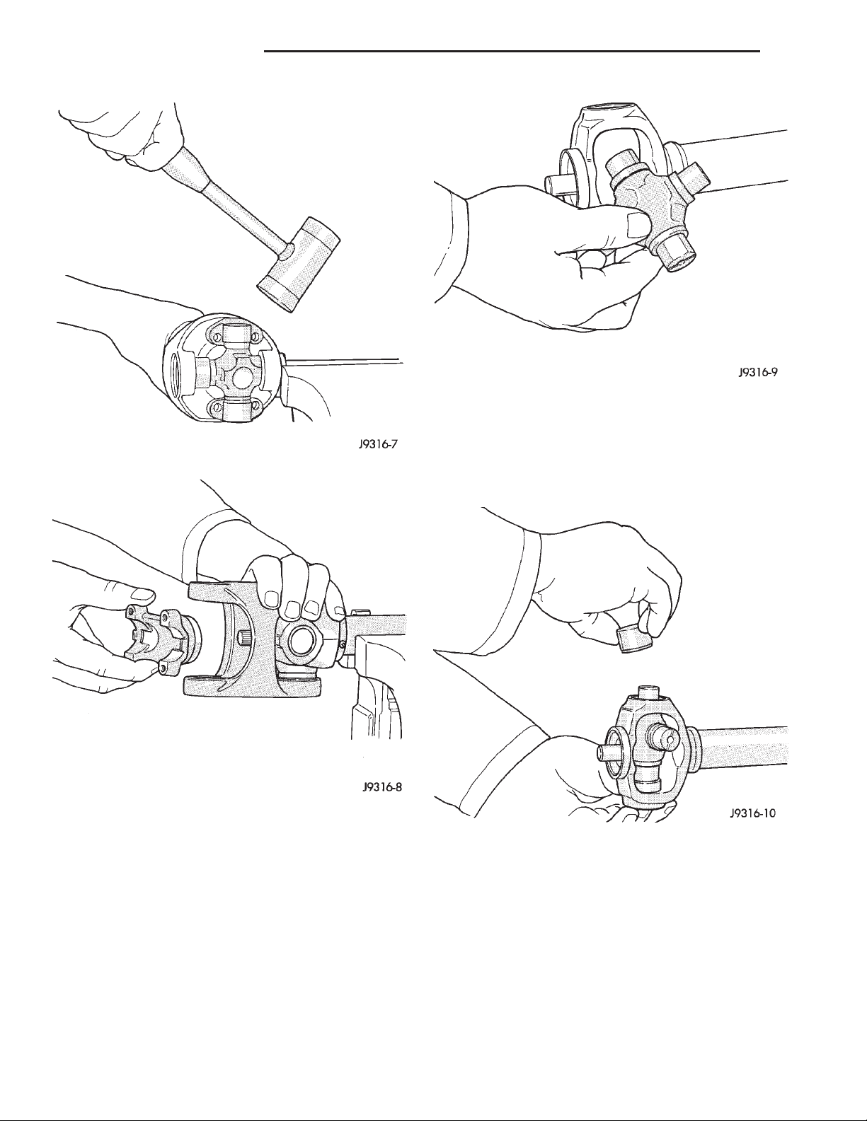
(6) Grasp the protruding bearing by vise jaws. Tap
the link yoke with a mallet and drift to dislodge the
bearing cap from the yoke (Fig. 25).
(7) Flip assembly and repeat Step 4, Step 5, and
Step 6 to remove the opposite bearing cap. This will
then allow removal of the cross centering kit assembly and spring (Fig. 26).
(8) Press the remaining bearing caps out the other
end of the link yoke as described above to complete
the disassembly.
Page 12
3 - 12 PROPELLER SHAFTS XJ
DISASSEMBLY AND ASSEMBLY (Continued)
Fig. 27 Install Cross In Yoke
(3) Place a bearing cap over the trunnion and
align the cap with the yoke bore (Fig. 28). Keep the
Fig. 25 Remove Bearing From Yoke
needle bearings upright in the bearing assembly. A
needle bearing lying at the bottom of the cap will
prevent proper assembly.
Fig. 26 Remove Centering Kit
ASSEMBLY
During assembly, ensure that the alignment
marks on the link yoke and propeller shaft
yoke are aligned.
(1) Apply extreme pressure (EP) N.L.G.I. Grade 1
or 2 grease to inside of yoke bores to aid in installation.
Fit a cross into the propeller shaft yoke (Fig. 27).
(2)
Fig. 28 Install Bearing Cap
(4) Press the bearing cap into the yoke bore
enough to install a snap ring (Fig. 29).
(5) Install a snap ring.
Page 13
XJ PROPELLER SHAFTS 3 - 13
DISASSEMBLY AND ASSEMBLY (Continued)
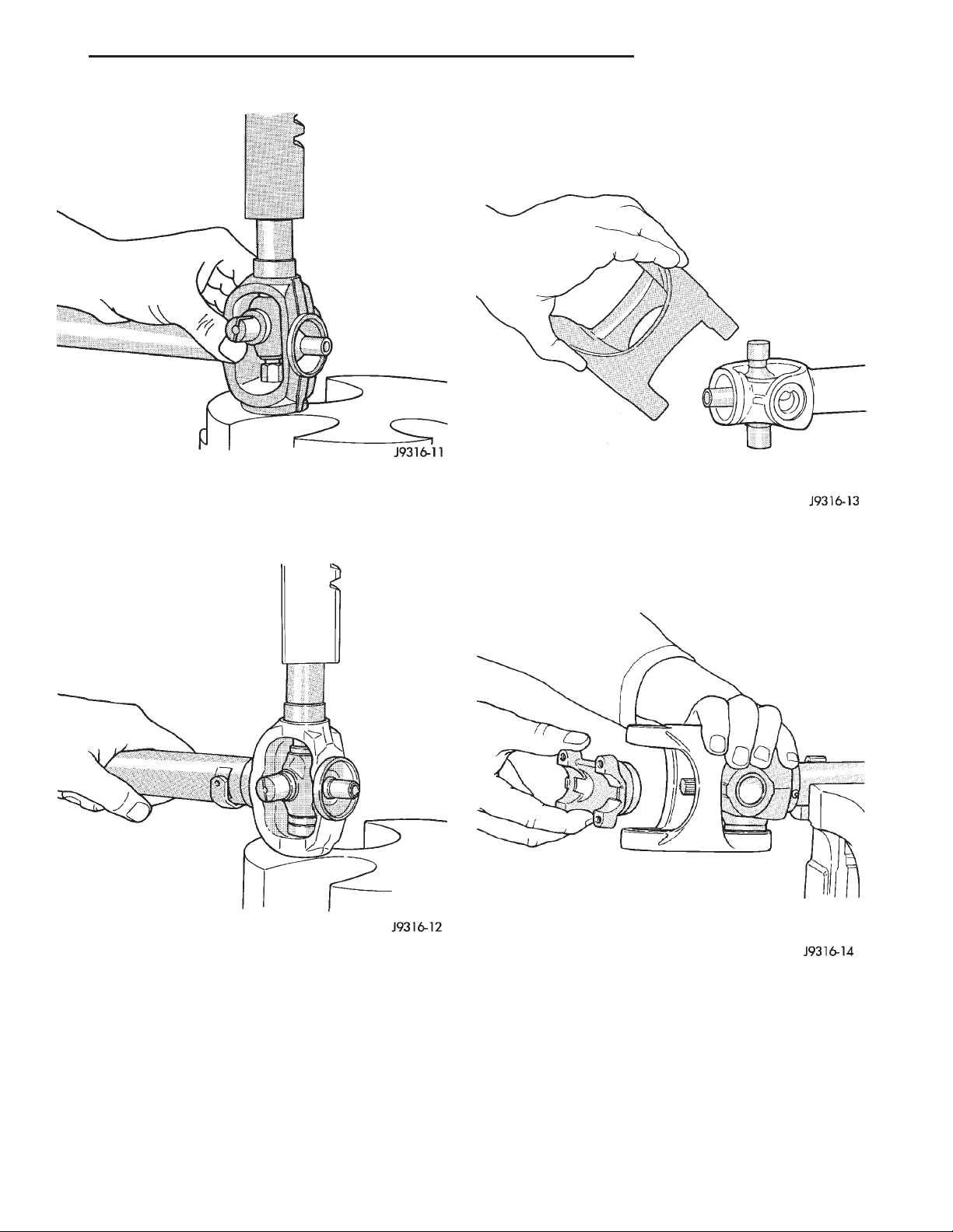
(7) Fit the link yoke on the remaining two trun-
nions and press both bearing caps into place (Fig.
31).
(8) Install snap rings.
Fig. 29 Press In Bearing Cap
(6) Flip the propeller shaft yoke and install the
bearing cap onto the opposite trunnion. Install a
snap ring (Fig. 30).
(9) Install the centering kit assembly inside the
link yoke making sure the spring is properly positioned (Fig. 32).
Fig. 31 Install Link Yoke
Fig. 30 Press In Bearing Cap
Fig. 32 Install Centering Kit
Page 14
3 - 14 PROPELLER SHAFTS XJ
DISASSEMBLY AND ASSEMBLY (Continued)
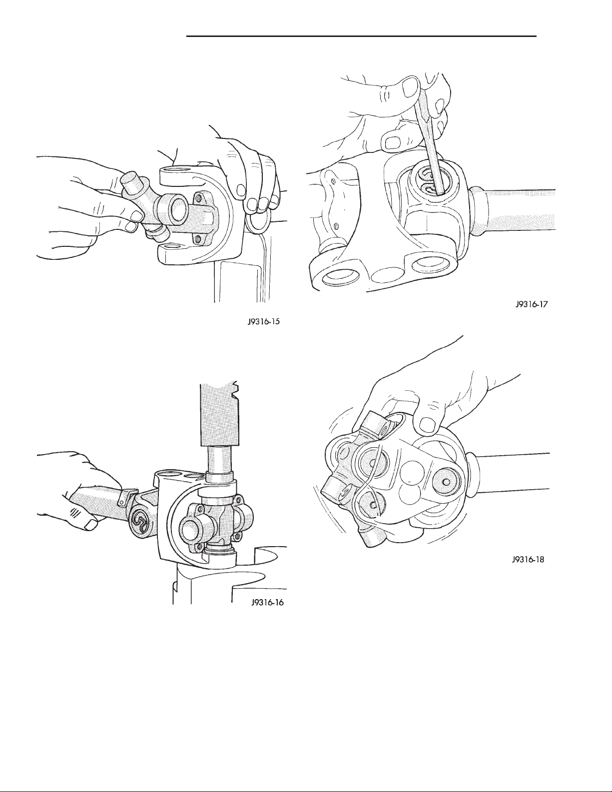
(10) Place two bearing caps on opposite trunnions
of the remaining cross. Fit the open trunnions into
the link yoke bores and the bearing caps into the
centering kit (Fig. 33).
Fig. 35 Seat Snap Rings In Groove
Fig. 33 Install Remaining Cross
(11) Press the remaining two bearing caps into
place and install snap rings (Fig. 34).
Fig. 34 Press In Bearing Cap
(12) Tap the snap rings to allow them to seat into
the grooves (Fig. 35).
(13) Check for proper assembly. Flex the joint
beyond center, it should snap over-center in both
directions when correctly assembled (Fig. 36).
(14) Install the propeller shaft.
Fig. 36 Check Assembly
CLEANING AND INSPECTION
PROPELLER SHAFT
(1) Clean all universal joint bores with cleaning
solvent and a wire brush.
(2) Inspect the yokes for distortion, cracks, and
worn bearing cap bores.
Page 15
XJ PROPELLER SHAFTS 3 - 15
ADJUSTMENTS
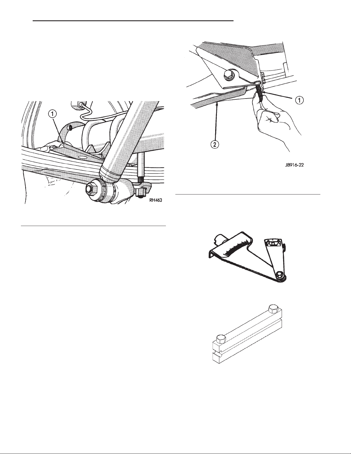
REAR AXLE PINION INPUT ANGLE
Adjust the rear axle pinion input angle on vehicles
equipped with leaf springs with tapered shims (Fig.
37). Install tapered shims between the springs and
axle pad to correct the angle. Refer to Group 2, Suspension, for additional information.
Fig. 38 Front Axle Angle Adjustment
1 – SHIM
2 – SUSPENSION ARM
Fig. 37 Pinion Angle Adjustment at Leaf Springs
1 – WEDGE
FRONT AXLE PINION INPUT ANGLE
Adjust the front axle pinion input angle at the
lower suspension arms with shims (Fig. 38). Adding
shims will decrease the pinion shaft angle but will
also increase the caster angle. The pinion shaft angle
has priority over the caster angle. Refer to Group 2,
Suspension, for additional information.
SPECIFICATIONS
PROPELLER SHAFTS AND U–JOINTS
DESCRIPTION TORQUE
Bolts, Transfer Case Yoke ..... 27N·m(20ft.lbs.)
Bolts, Axle Yoke............. 19N·m(14ft.lbs.)
Bolts, Axle Yoke............. 19N·m(14ft.lbs.)
SPECIAL TOOLS
PROPELLER SHAFT
Inclinometer—7663
Boot Clamp Installer—C-4975-A
Page 16
3 - 16 TUBE, 181, AND 186 FBI AXLE XJ
TUBE, 181, AND 186 FBI AXLE
TABLE OF CONTENTS
page page
DESCRIPTION AND OPERATION
181 FBI AXLE............................16
186 FBI AXLE............................17
LUBRICANT.............................17
STANDARD DIFFERENTIAL.................18
DIAGNOSIS AND TESTING
GENERAL INFORMATION ..................19
GEAR NOISE............................21
BEARING NOISE .........................21
LOW SPEED KNOCK......................21
VIBRATION .............................21
DRIVELINE SNAP ........................21
SERVICE PROCEDURES
LUBRICANT CHANGE .....................21
REMOVAL AND INSTALLATION
DRIVE AXLE ASSEMBLY ...................22
TUBE AXLE ASSEMBLY....................23
AXLE SHAFT—CARDAN U-JOINT ............23
181 FBI PINION SHAFT SEAL ...............24
186 FBI PINION SHAFT SEAL ...............26
COLLAPSIBLE SPACER....................27
HUB BEARING AND AXLE SHAFT ............30
STEERING KNUCKLE AND BALL STUDS.......31
AXLE BUSHING REPLACEMENT.............33
DIFFERENTIAL ..........................33
DIFFERENTIAL SIDE BEARINGS .............36
AXLE SHAFT OIL SEAL ....................36
181 FBI PINION ..........................36
186 FBI PINION ..........................41
RING GEAR.............................45
DISASSEMBLY AND ASSEMBLY
STANDARD DIFFERENTIAL.................46
FINAL ASSEMBLY ........................47
CLEANING AND INSPECTION
CARDAN U-JOINT ........................47
AXLE COMPONENTS .....................47
ADJUSTMENTS
181 FBI PINION GEAR DEPTH...............48
186 FBI PINION GEAR DEPTH...............50
181 FBI DIFFERENTIAL BEARING PRELOAD
AND GEAR BACKLASH ..................52
186 FBI DIFFERENTIAL BEARING PRELOAD
AND GEAR BACKLASH ..................56
GEAR CONTACT PATTERN ANALYSIS ........59
SPECIFICATIONS
181 FBI AXLE............................61
186 FBI AXLE............................61
TORQUE ...............................61
SPECIAL TOOLS
181 and 186 FBI AXLE .....................61
DESCRIPTION AND OPERATION
181 FBI AXLE
DESCRIPTION
The 181 Front Beam-design Iron (FBI) axle consists of a cast iron differential housing with axle
shaft tubes extending from either side. The tubes are
pressed into the differential housing and welded.
The integral type housing, hypoid gear design has
the centerline of the pinion set above the centerline
of the ring gear.
The axle has a fitting for a vent hose used to
relieve internal pressure caused by lubricant vaporization and internal expansion.
The axles are equipped with semi–floating axle
shafts, meaning that loads are supported by the hub
bearings. The axle shafts are retained by nuts at the
hub bearings. The hub bearings are bolted to the
steering knuckle at the outboard end of the axle tube
yoke. The hub bearings are serviced as an assembly.
For vehicles with ABS brakes, the ABS wheel
speed sensors are attached to the knuckle assemblies. The tone rings for the ABS system are pressed
onto the axle shaft. Do not damage ABS tone
wheel or the sensor when removing axle shafts.
The stamped steel cover provides a means for
inspection and servicing the differential.
The 181 FBI axle has the assembly part number
and gear ratio listed on a tag. The tag is attached to
the housing cover by a cover bolt. Build date identification codes are stamped on the cover side of the
axle shaft tube.
The differential case is a one–piece design. The differential pinion mate shaft is retained with a roll
pin. Differential bearing preload and ring gear backlash is adjusted by the use of shims (select thickness). The shims are located between the differential
bearing cones and case. Pinion bearing preload is set
and maintained by the use of shims (select thickness).
Page 17
XJ TUBE, 181, AND 186 FBI AXLE 3 - 17
DESCRIPTION AND OPERATION (Continued)
OPERATION
The axle receives power from the transfer case
through the front propeller shaft. The front propeller
shaft is connected to the pinion gear which rotates
the differential through the gear mesh with the ring
gear bolted to the differential case. The engine power
is transmitted to the axle shafts through the pinion
mate and side gears. The side gears are splined to
the axle shafts.
186 FBI AXLE
DESCRIPTION
The 186 Front Beam-design Iron (FBI) axle consists of a cast iron differential housing with axle
shaft tubes extending from either side. The tubes are
pressed into the differential housing and welded.
The integral type housing, hypoid gear design has
the centerline of the pinion set below the centerline
of the ring gear.
The axle has a fitting for a vent hose used to
relieve internal pressure caused by lubricant vaporization and internal expansion.
The axles are equipped with semi–floating axle
shafts, meaning that loads are supported by the hub
bearings. The axle shafts are retained by nuts at the
hub bearings. The hub bearings are bolted to the
steering knuckle at the outboard end of the axle tube
yoke. The hub bearings are serviced as an assembly.
For vehicles with ABS brakes, the ABS wheel
speed sensors are attached to the knuckle assemblies. The tone rings for the ABS system are pressed
onto the axle shaft. Do not damage ABS tone
wheel or the sensor when removing axle shafts.
The stamped steel cover provides a means for
inspection and servicing the differential.
The 186 FBI axle has the assembly part number
and gear ratio listed on a tag. The tag is attached to
the housing cover by a cover bolt. Build date identification codes are stamped on the cover side of the
axle shaft tube.
The differential case is a one–piece design. The differential pinion mate shaft is retained with a roll
pin. Differential bearing preload and ring gear backlash is adjusted by the use of shims (select thickness). The shims are located between the differential
bearing cones and case. Pinion bearing preload is set
and maintained by the use of a collapsible spacer.
OPERATION
The axle receives power from the transfer case
through the front propeller shaft. The front propeller
shaft is connected to the pinion gear which rotates
the differential through the gear mesh with the ring
gear bolted to the differential case. The engine power
is transmitted to the axle shafts through the pinion
mate and side gears. The side gears are splined to
the axle shafts.
LUBRICANT
DESCRIPTION
A multi–purpose, hypoid gear lubricant which conforms to the following specifications should be used.
Mopart Hypoid Gear Lubricant conforms to all of
these specifications.
• The lubricant should have MIL–L–2105C and
API GL 5 quality specifications.
• Lubricant is a thermally stable SAE 80W–90
gear lubricant.
• Lubricant for axles intended for heavy-duty or
trailer tow use is SAE 75W–140 SYNTHETIC gear
lubricant.
The 181 FBI axle lubricant capacity is 1.2 L (2.5
pts.). The 186 FBI axle lubricant capacity is 1.18 L
(2.5 pts.).
CAUTION: If axle is submerged in water, lubricant
must be replaced immediately to avoid possible
premature axle failure.
Page 18
3 - 18 TUBE, 181, AND 186 FBI AXLE XJ
DESCRIPTION AND OPERATION (Continued)
STANDARD DIFFERENTIAL
DESCRIPTION
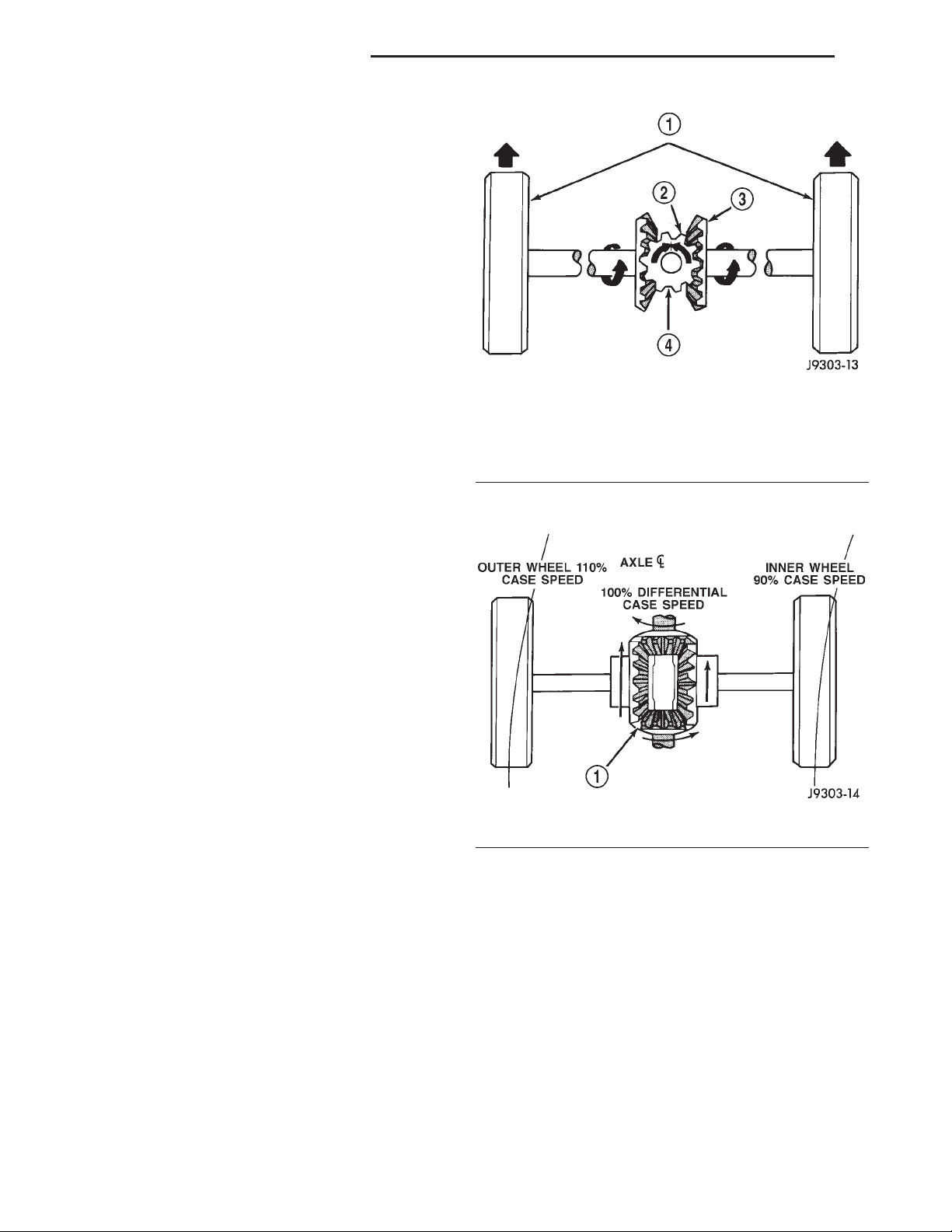
The differential gear system divides the torque
between the axle shafts. It allows the axle shafts to
rotate at different speeds when turning corners.
Each differential side gear is splined to an axle
shaft. The pinion gears are mounted on a pinion
mate shaft and are free to rotate on the shaft. The
pinion gear is fitted in a bore in the differential case
and is positioned at a right angle to the axle shafts.
OPERATION
In operation, power flow occurs as follows:
• The pinion gear rotates the ring gear
• The ring gear (bolted to the differential case)
rotates the case
• The differential pinion gears (mounted on the
pinion mate shaft in the case) rotate the side gears
• The side gears (splined to the axle shafts) rotate
the shafts
During straight-ahead driving, the differential pinion gears do not rotate on the pinion mate shaft. This
occurs because input torque applied to the gears is
divided and distributed equally between the two side
gears. As a result, the pinion gears revolve with the
pinion mate shaft but do not rotate around it (Fig. 1).
When turning corners, the outside wheel must
travel a greater distance than the inside wheel to
complete a turn. The difference must be compensated
for to prevent the tires from scuffing and skidding
through turns. To accomplish this, the differential
allows the axle shafts to turn at unequal speeds (Fig.
2). In this instance, the input torque applied to the
pinion gears is not divided equally. The pinion gears
now rotate around the pinion mate shaft in opposite
directions. This allows the side gear and axle shaft
attached to the outside wheel to rotate at a faster
speed.
Fig. 1 Differential Operation—Straight Ahead Driving
1 – IN STRAIGHT AHEAD DRIVING EACH WHEEL ROTATES AT
100% OF CASE SPEED
2 – PINION GEAR
3 – SIDE GEAR
4 – PINION GEARS ROTATE WITH CASE
Fig. 2 Differential Operation—On Turns
1 – PINION GEARS ROTATE ON PINION SHAFT
Page 19
XJ TUBE, 181, AND 186 FBI AXLE 3 - 19
DIAGNOSIS AND TESTING
GENERAL INFORMATION
Axle bearing problem conditions are usually caused
by:
• Insufficient or incorrect lubricant.
• Foreign matter/water contamination.
• Incorrect bearing preload torque adjustment.
• Incorrect backlash.
Axle gear problem conditions are usually the result
of:
• Insufficient lubrication.
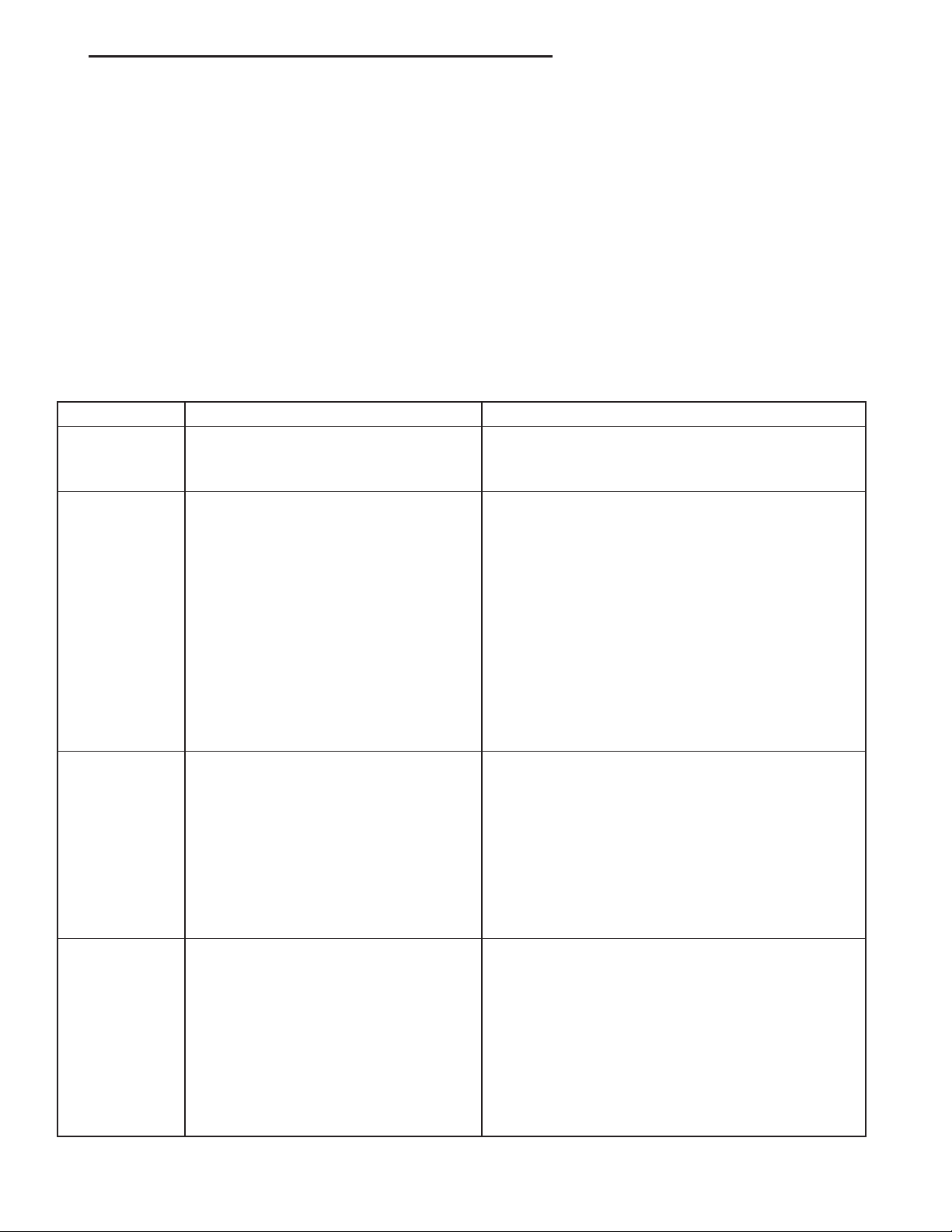
DIAGNOSTIC CHART
Condition Possible Causes Correction
Wheel Noise 1. Wheel loose. 1. Tighten loose nuts.
2. Faulty, brinelled wheel bearing. 2. Replace bearing.
Axle Shaft
Noise
1. Misaligned axle tube. 1. Inspect axle tube alignment. Correct as
2. Bent or sprung axle shaft. 2. Inspect and correct as necessary.
3. End-play in pinion bearings. 3. Refer to pinion pre-load information and correct
4. Excessive gear backlash between
the ring gear and pinion.
5. Improper adjustment of pinion gear
bearings.
6. Loose pinion yoke nut. 6. Tighten the pinion yoke nut.
7. Scuffed gear tooth contact surfaces. 7. Inspect and replace as necessary.
• Incorrect or contaminated lubricant.
• Overloading (excessive engine torque) or exceed-
ing vehicle weight capacity.
• Incorrect clearance or backlash adjustment.
Axle component breakage is most often the result
of:
• Severe overloading.
• Insufficient lubricant.
• Incorrect lubricant.
• Improperly tightened components.
• Differential housing bores not square to each
other.
necessary.
as necessary.
4. Check adjustment of the ring gear and pinion
backlash. Correct as necessary.
5. Adjust the pinion bearings pre-load.
Axle Shaft
Broke
Differential
Cracked
1. Misaligned axle tube. 1. Replace the broken shaft after correcting tube
mis-alignment.
2 Vehicle overloaded. 2. Replace broken shaft and avoid excessive weight
on vehicle.
3. Erratic clutch operation. 3. Replace broken shaft and avoid or correct erratic
clutch operation.
4. Grabbing clutch. 4. Replace broken shaft and inspect and repair
clutch as necessary.
1. Improper adjustment of the
differential bearings.
2. Excessive ring gear backlash. 2. Replace case and inspect gears and bearings for
3. Vehicle overloaded. 3. Replace case and inspect gears and bearings for
4. Erratic clutch operation. 4. Replace case and inspect gears and bearings for
1. Replace case and inspect gears and bearings for
further damage. Set differential bearing pre-load
properly.
further damage. Set ring gear backlash properly.
further damage. Avoid excessive vehicle weight.
further damage. Avoid erratic use of clutch.
Page 20
3 - 20 TUBE, 181, AND 186 FBI AXLE XJ
DIAGNOSIS AND TESTING (Continued)
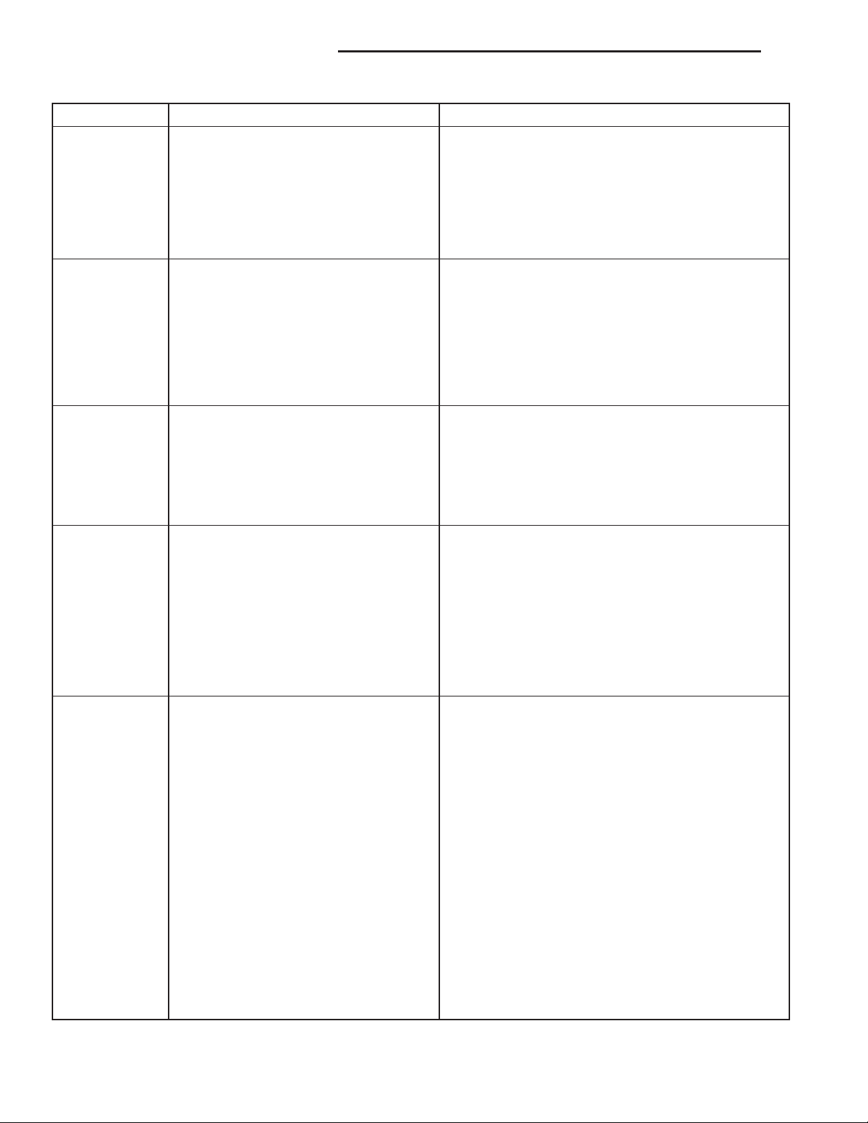
Condition Possible Causes Correction
Differential
Gears Scored
Loss Of
Lubricant
Axle
Overheating
Gear Teeth
Broke
1. Insufficient lubrication. 1. Replace scored gears. Fill differential with the
correct fluid type and quantity.
2. Improper grade of lubricant. 2. Replace scored gears. Fill differential with the
correct fluid type and quantity.
3. Excessive spinning of one wheel/tire. 3. Replace scored gears. Inspect all gears, pinion
bores, and shaft for damage. Service as necessary.
1. Lubricant level too high. 1. Drain lubricant to the correct level.
2. Worn axle shaft seals. 2. Replace seals.
3. Cracked differential housing. 3. Repair as necessary.
4. Worn pinion seal. 4. Replace seal.
5. Worn/scored yoke. 5. Replace yoke and seal.
6. Axle cover not properly sealed. 6. Remove, clean, and re-seal cover.
1. Lubricant level low. 1. Fill differential to correct level.
2. Improper grade of lubricant. 2. Fill differential with the correct fluid type and
quantity.
3. Bearing pre-loads too high. 3. Re-adjust bearing pre-loads.
4. Insufficient ring gear backlash. 4. Re-adjust ring gear backlash.
1. Overloading. 1. Replace gears. Examine other gears and bearings
for possible damage.
2. Erratic clutch operation. 2. Replace gears and examine the remaining parts
for damage. Avoid erratic clutch operation.
3. Ice-spotted pavement. 3. Replace gears and examine remaining parts for
damage.
4. Improper adjustments. 4. Replace gears and examine remaining parts for
damage. Ensure ring gear backlash is correct.
Axle Noise 1. Insufficient lubricant. 1. Fill differential with the correct fluid type and
quantity.
2. Improper ring gear and pinion
adjustment.
3. Unmatched ring gear and pinion. 3. Replace gears with a matched ring gear and
4. Worn teeth on ring gear and/or
pinion.
5. Loose pinion bearings. 5. Adjust pinion bearing pre-load.
6. Loose differential bearings. 6. Adjust differential bearing pre-load.
7. Mis-aligned or sprung ring gear. 7. Measure ring gear run-out. Replace components
8. Loose differential bearing cap bolts. 8. Inspect differential components and replace as
9. Housing not machined properly. 9. Replace housing.
2. Check ring gear and pinion contact pattern.
pinion.
4. Replace ring gear and pinion.
as necessary.
necessary. Ensure that the bearing caps are torqued
tot he proper specification.
Page 21
XJ TUBE, 181, AND 186 FBI AXLE 3 - 21
DIAGNOSIS AND TESTING (Continued)
GEAR NOISE
Axle gear noise can be caused by insufficient lubricant, incorrect backlash, tooth contact, worn/damaged
gears, or the carrier housing not having the proper
offset and squareness.
Gear noise usually happens at a specific speed
range. The noise can also occur during a specific type
of driving condition. These conditions are acceleration, deceleration, coast, or constant load.
When road testing, first warm-up the axle fluid by
driving the vehicle at least 5 miles and then accelerate the vehicle to the speed range where the noise is
the greatest. Shift out-of-gear and coast through the
peak–noise range. If the noise stops or changes
greatly:
• Check for insufficient lubricant.
• Incorrect ring gear backlash.
• Gear damage.
Differential side gears and pinions can be checked
by turning the vehicle. They usually do not cause
noise during straight–ahead driving when the gears
are unloaded. The side gears are loaded during vehicle turns. A worn pinion mate shaft can also cause a
snapping or a knocking noise.
BEARING NOISE
The axle shaft, differential and pinion bearings can
all produce noise when worn or damaged. Bearing
noise can be either a whining, or a growling sound.
Pinion bearings have a constant–pitch noise. This
noise changes only with vehicle speed. Pinion bearing
noise will be higher pitched because it rotates at a
faster rate. Drive the vehicle and load the differential. If bearing noise occurs, the rear pinion bearing
is the source of the noise. If the bearing noise is
heard during a coast, the front pinion bearing is the
source.
Worn or damaged differential bearings usually produce a low pitch noise. Differential bearing noise is
similar to pinion bearing noise. The pitch of differential bearing noise is also constant and varies only
with vehicle speed.
Axle shaft bearings produce noise and vibration
when worn or damaged. The noise generally changes
when the bearings are loaded. Road test the vehicle.
Turn the vehicle sharply to the left and to the right.
This will load the bearings and change the noise
level. Where axle bearing damage is slight, the noise
is usually not noticeable at speeds above 30 mph.
LOW SPEED KNOCK
Low speed knock is generally caused by a worn
U–joint or by worn side–gear thrust washers. A worn
pinion shaft bore will also cause low speed knock.
VIBRATION
Vibration at the rear of the vehicle is usually
caused by a:
• Damaged drive shaft.
• Missing drive shaft balance weight(s).
• Worn or out–of–balance wheels.
• Loose wheel lug nuts.
• Worn U–joint(s).
• Loose/broken springs.
• Damaged axle shaft bearing(s).
• Loose pinion gear nut.
• Excessive pinion yoke run out.
• Bent axle shaft(s).
Check for loose or damaged front–end components
or engine/transmission mounts. These components
can contribute to what appears to be a rear–end
vibration. Do not overlook engine accessories, brackets and drive belts.
All driveline components should be examined
before starting any repair.
Refer to Group 22, Wheels and Tires, for additional
vibration information.
DRIVELINE SNAP
A snap or clunk noise when the vehicle is shifted
into gear (or the clutch engaged), can be caused by:
• High engine idle speed.
• Transmission shift operation.
• Loose engine/transmission/transfer case mounts.
• Worn U–joints.
• Loose spring mounts.
• Loose pinion gear nut and yoke.
• Excessive ring gear backlash.
• Excessive side gear to case clearance.
The source of a snap or a clunk noise can be determined with the assistance of a helper. Raise the vehicle on a hoist with the wheels free to rotate. Instruct
the helper to shift the transmission into gear. Listen
for the noise, a mechanics stethoscope is helpful in
isolating the source of a noise.
SERVICE PROCEDURES
LUBRICANT CHANGE
(1) Raise and support the vehicle.
(2) Remove the lubricant fill hole plug from the
differential housing cover.
(3) Remove the differential housing cover and
drain the lubricant from the housing.
(4) Clean the housing cavity with a flushing oil,
light engine oil or lint free cloth. Do not use water,
steam, kerosene or gasoline for cleaning.
(5) Remove the sealant from the housing and cover
surfaces. Use solvent to clean the mating surfaces.
Page 22
3 - 22 TUBE, 181, AND 186 FBI AXLE XJ
SERVICE PROCEDURES (Continued)
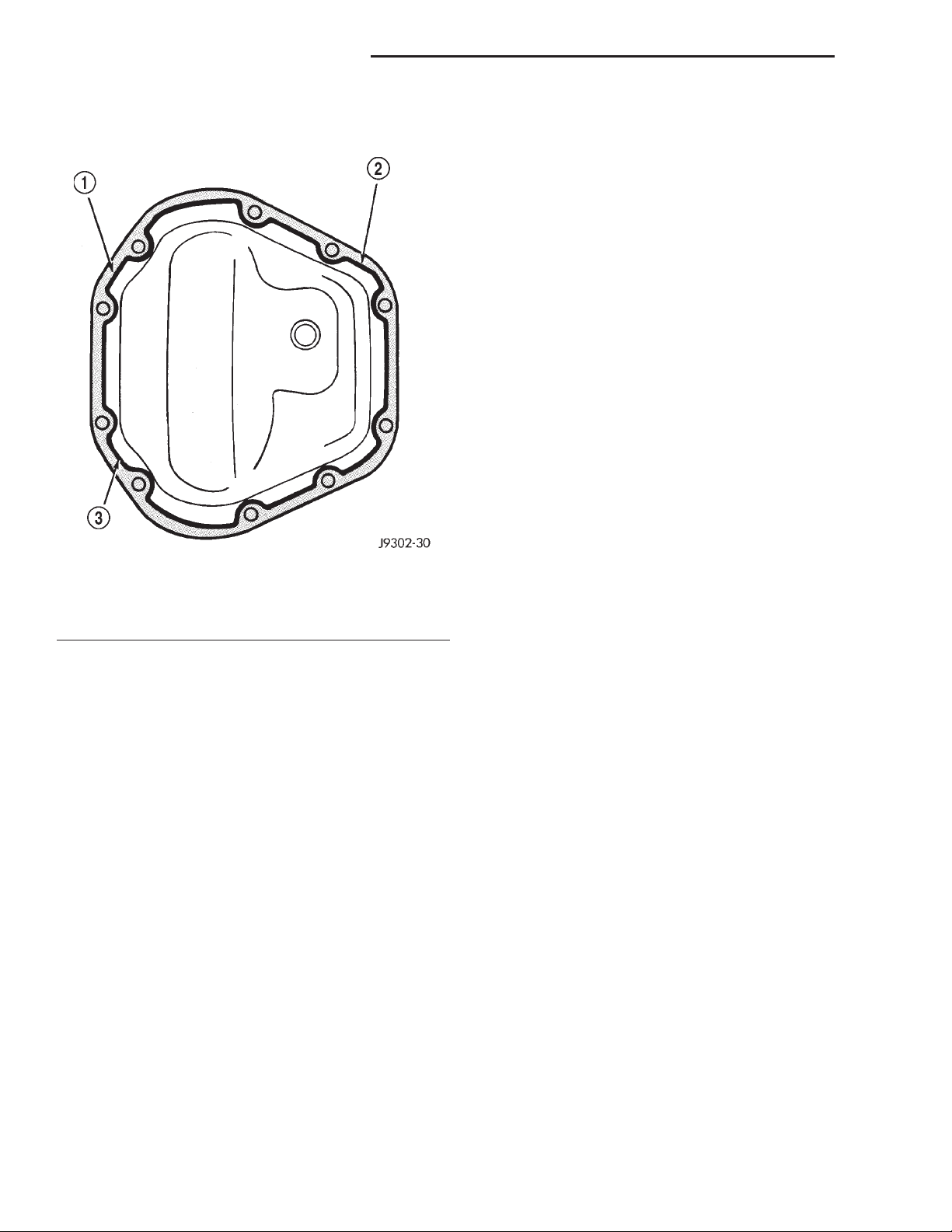
(6) Apply a bead of Mopart Silicone Rubber Seal-
ant, or equivalent, to the housing cover (Fig. 3).
Fig. 3 Typical Housing Cover With Sealant
1 – SEALING SURFACE
2 – CONTOUR OF BEAD
3 – BEAD THICKNESS 6.35mm (1/4”)
Install the housing cover within 5 minutes
after applying the sealant.
(7) Install the cover and any identification tag.
Tighten the cover bolts in a criss–cross pattern to 41
N·m (30 ft. lbs.) torque.
(8) Refill the differential with Mopart Hypoid
Gear Lubricant, or equivalent, to bottom of the fill
plug hole. Refer to the Lubricant Specifications in
this group for the quantity necessary.
(9) Install the fill hole plug and lower the vehicle.
Tighten fill plug to 34 N·m (25 ft. lbs.).
REMOVAL AND INSTALLATION
DRIVE AXLE ASSEMBLY
REMOVAL
(1) Raise and support the vehicle.
(2) Position a suitable lifting device under the
axle.
(3) Secure axle to device.
(4) Remove the wheels and tires.
(5) Remove the brake rotors and calipers from the
axle. Refer to Group 5, Brakes, for proper procedures.
(6) Disconnect the wheel sensor wiring harness
from the vehicle wiring harness, if necessary.
(7) Disconnect the vent hose from the axle shaft
tube.
(8) Mark the propeller shaft and yoke for installa-
tion alignment reference.
(9) Remove propeller shaft.
(10) Disconnect stabilizer bar links at the axle.
(11) Disconnect shock absorbers from axle brack-
ets.
(12) Disconnect track bar.
(13) Disconnect the tie rod and drag link from the
steering knuckle. Refer to Group 2, Suspension, for
proper procedures.
(14) Disconnect the steering damper from the axle
bracket.
(15) Disconnect the upper and lower suspension
arms from the axle brackets.
(16) Lower the lifting device enough to remove the
axle. The coil springs will drop with the axle.
(17) Remove the coil springs from the axle.
INSTALLATION
CAUTION: The weight of the vehicle must be supported by the springs before suspension arms and
track bar fasteners can be tightened. If the springs
are not at their normal ride position, ride height and
handling could be affected.
(1) Install the springs and retainer clips. Tighten
the retainer bolts to 21 N·m (16 ft. lbs.) torque.
(2) Support the axle on a suitable lifting device
and position axle under the vehicle.
(3) Raise the axle and align it with the spring
pads.
(4) Position the upper and lower suspension arms
in the axle brackets. Loosely install bolts and nuts to
hold suspension arms to the axle brackets.
(5) Connect the vent hose to the axle shaft tube.
(6) Connect the track bar to the axle bracket.
Loosely install the bolt to hold the track bar to the
axle bracket.
(7) Install the shock absorbers and tighten the
bolts to 23 N·m (17 ft. lbs.) torque.
(8) Install the stabilizer bar links to the axle
brackets. Tighten the nut to 95 N·m (70 ft. lbs.)
torque.
(9) Install the drag link and tie rod to the steering
knuckles. Refer to Group 2, Suspension, for proper
procedures.
(10) Install the steering damper to the axle
bracket and tighten the nut to 75 N·m (55 ft. lbs.)
torque.
(11) Install the brake rotors and calipers. Refer to
Group 5, Brakes, for the proper procedures.
(12) Connect the wheel speed sensor wiring harness to the vehicle wiring harness, if necessary.
Page 23
XJ TUBE, 181, AND 186 FBI AXLE 3 - 23
REMOVAL AND INSTALLATION (Continued)
(13) Align the previously made marks on the pro-
peller shaft and the yoke.
(14) Install the straps and bolts to hold the propel-
ler shaft to the yoke.
(15) Check and fill axle lubricant. Refer to the
Lubricant Specifications in this group for the quantity necessary.
(16) Install the wheel and tire assemblies.
(17) Remove the lifting device from the axle and
lower the vehicle.
(18) Tighten the upper suspension arm nuts to 75
N·m (55 ft. lbs.) torque. Tighten the lower suspension
arm nuts to 115 N·m (85 ft. lbs.) torque.
(19) Tighten the track bar bolt at the axle bracket
to 100 N·m (74 ft. lbs.) torque.
(20) Check the front wheel alignment.
TUBE AXLE ASSEMBLY
REMOVAL
(1) Raise and support the vehicle.
(2) Position a suitable lifting device under the
axle.
(3) Secure axle to device.
(4) Remove the wheels and tires.
(5) Remove the brake rotors and calipers from the
axle. Refer to Group 5, Brakes, for proper procedures.
(6) Disconnect the wheel sensor wiring harness
from the vehicle wiring harness, if necessary.
(7) Disconnect stabilizer bar links at the axle.
(8) Disconnect shock absorbers from axle brackets.
(9) Disconnect track bar.
(10) Disconnect the tie rod and drag link from the
steering knuckle. Refer to Group 2, Suspension, for
proper procedures.
(11) Disconnect the steering damper from the axle
bracket.
(12) Disconnect the upper and lower suspension
arms from the axle brackets.
(13) Lower the lifting device enough to remove the
axle. The coil springs will drop with the axle.
(14) Remove the coil springs from the axle.
INSTALLATION
CAUTION: The weight of the vehicle must be supported by the springs before suspension arms and
track bar fasteners can be tightened. If the springs
are not at their normal ride position, ride height and
handling could be affected.
(1) Install the springs and retainer clips. Tighten
the retainer bolts to 21 N·m (16 ft. lbs.) torque.
(2) Support the axle on a suitable lifting device
and position axle under the vehicle.
(3) Raise the axle and align it with the spring
pads.
(4) Position the upper and lower suspension arms
in the axle brackets. Loosely install bolts and nuts to
hold suspension arms to the axle brackets.
(5) Connect the track bar to the axle bracket.
Loosely install the bolt to hold the track bar to the
axle bracket.
(6) Install the shock absorbers and tighten the
bolts to 23 N·m (17 ft. lbs.) torque.
(7) Install the stabilizer bar links to the axle
brackets. Tighten the nut to 95 N·m (70 ft. lbs.)
torque.
(8) Install the drag link and tie rod to the steering
knuckles. Refer to Group 2, Suspension, for proper
procedures.
(9) Install the steering damper to the axle bracket
and tighten the nut to 75 N·m (55 ft. lbs.) torque.
(10) Install the brake rotors and calipers. Refer to
Group 5, Brakes, for the proper procedures.
(11) Connect the wheel speed sensor wiring harness to the vehicle wiring harness, if necessary.
(12) Install the wheel and tire assemblies.
(13) Remove the lifting device from the axle and
lower the vehicle.
(14) Tighten the upper suspension arm nuts to 75
N·m (55 ft. lbs.) torque. Tighten the lower suspension
arm nuts to 115 N·m (85 ft. lbs.) torque.
(15) Tighten the track bar bolt at the axle bracket
to 100 N·m (74 ft. lbs.) torque.
(16) Check the front wheel alignment.
AXLE SHAFT—CARDAN U-JOINT
Single cardan U–joint components are not serviceable. If defective, they must be replaced as a unit. If
the bearings, seals, spider, or bearing caps are damaged or worn, replace the complete U–joint.
REMOVAL
CAUTION: Clamp only the narrow forged portion of
the yoke in the vise. Also, to avoid distorting the
yoke, do not over tighten the vise jaws.
(1) Remove axle shaft.
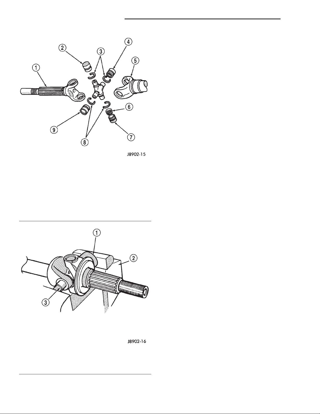
(2) Remove the bearing cap retaining snap rings
(Fig. 4).
It can be helpful to saturate the bearing caps
with penetrating oil prior to removal.
(3) Locate a socket where the inside diameter is
larger in diameter than the bearing cap. Place the
socket (receiver) against the yoke and around the
perimeter of the bearing cap to be removed.
(4) Locate a socket where the outside diameter is
smaller in diameter than the bearing cap. Place the
socket (driver) against the opposite bearing cap.
(5) Position the yoke with the sockets in a vise
(Fig. 5).
Page 24
3 - 24 TUBE, 181, AND 186 FBI AXLE XJ
REMOVAL AND INSTALLATION (Continued)
(6) Compress the vise jaws to force the bearing cap
into the larger socket (receiver).
(7) Release the vise jaws. Remove the sockets and
bearing cap that was partially forced out of the yoke.
(8) Repeat the above procedure for the remaining
bearing cap.
(9) Remove the remaining bearing cap, bearings,
seals and spider from the propeller shaft yoke.
INSTALLATION
(1) Pack the bearing caps 1/3 full of wheel bearing
lubricant. Apply extreme pressure (EP), lithium–base
lubricant to aid in installation.
(2) Position the spider in the yoke. Insert the seals
and bearings. Tap the bearing caps into the yoke
bores far enough to hold the spider in position.
(3) Place the socket (driver) against one bearing
cap. Position the yoke with the socket wrench in a
vise.
Fig. 4 Axle Shaft Outer U–Joint
1 – SHAFT YOKE
2 – BEARING CAP
3 – SNAP RINGS
4 – BEARING CAP
5 – SPINDLE YOKE
6 – BEARING
7 – BEARING CAP
8 – SNAP RINGS
9 – BEARING CAP
(4) Compress the vise to force the bearing caps
into the yoke. Force the caps enough to install the
retaining clips.
(5) Install the bearing cap retaining clips.
(6) Install axle shaft.
181 FBI PINION SHAFT SEAL
REMOVAL
(1) Raise and support the vehicle.
(2) Remove wheel and tire assemblies.
(3) Remove brake rotors and calipers. Refer to
Group 5, Brakes, for proper procedures.
(4) Mark the propeller shaft and pinion yoke for
installation reference.
(5) Remove the propeller shaft from the yoke.
(6) Rotate the pinion gear three or four times.
(7) Measure the amount of torque necessary to
rotate the pinion gear with a (in. lbs.) dial-type
torque wrench. Record the torque reading for installation reference.
(8) Using Holder 6958 to hold the pinion yoke,
remove the pinion nut and washer.
(9) Use Remover C-452 and Wrench C-3281 to
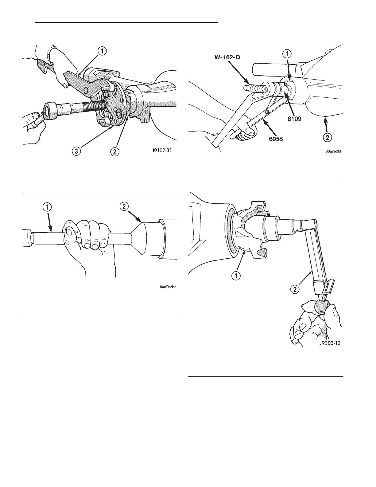
remove the pinion yoke (Fig. 6).
(10) Use a suitable pry tool or a slide hammer
mounted screw to remove the pinion shaft seal.
Fig. 5 Yoke Bearing Cap Removal
1 – LARGE-DIAMETER SOCKET WRENCH
2 – VISE
3 – SMALL-DIAMETER SOCKET WRENCH
INSTALLATION
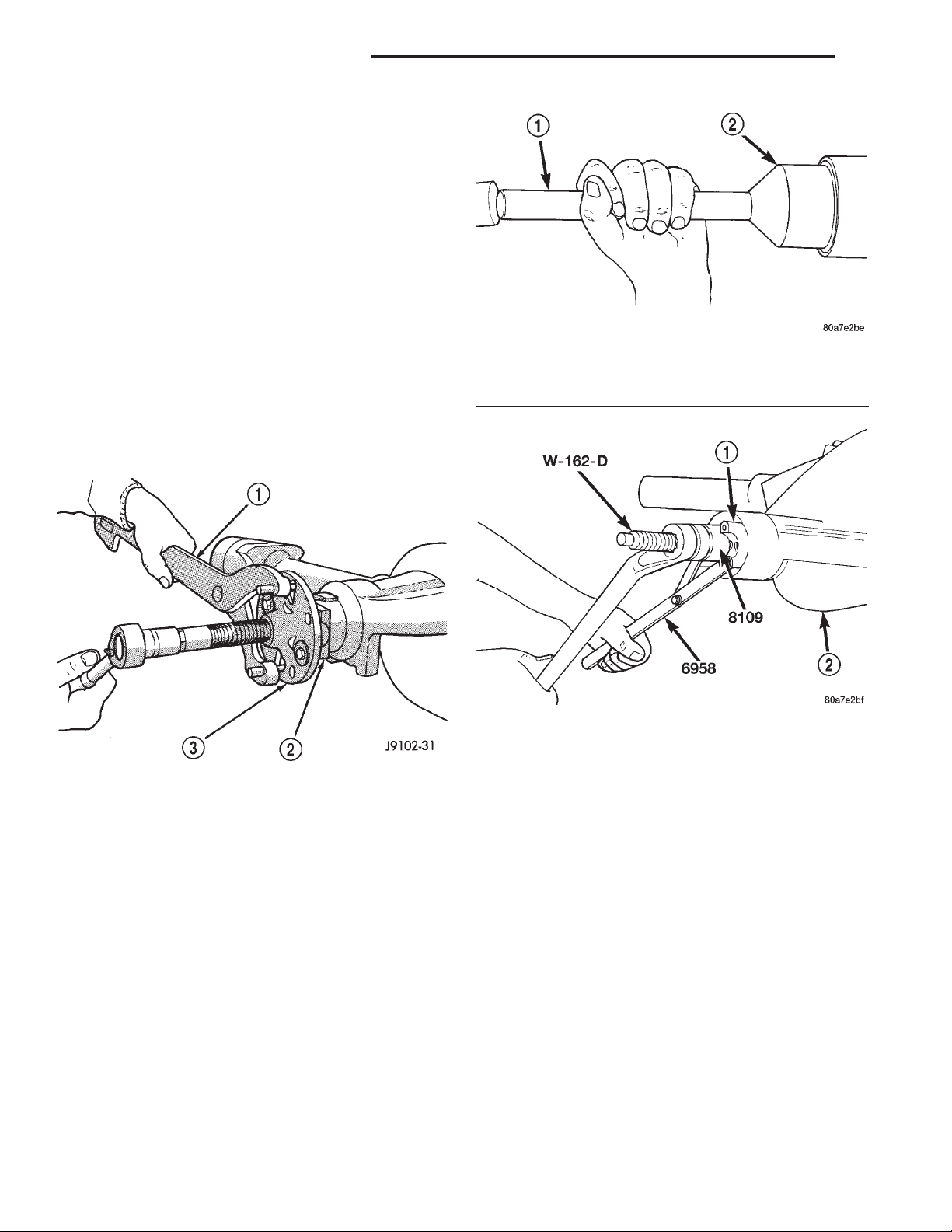
(1) Apply a light coating of gear lubricant on the
lip of pinion seal. Install seal with Installer C-3972-A
and Handle C-4171 (Fig. 7).
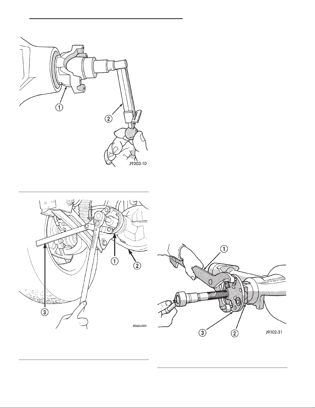
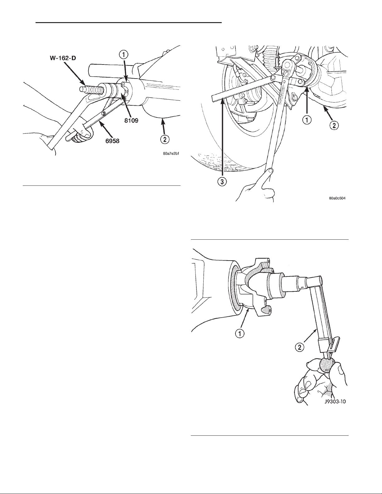
(2) Install yoke on the pinion gear with Installer
W-162–D, Cup 8109, and Holder 6958 (Fig. 8).
Page 25
XJ TUBE, 181, AND 186 FBI AXLE 3 - 25
REMOVAL AND INSTALLATION (Continued)
Fig. 6 Pinion Yoke Removal
1 – SPECIAL TOOL C-3281
2 – YOKE
3 – SPECIAL TOOL C-452
Fig. 7 Pinion Seal Installation
1 – SPECIAL TOOL C-4171
2 – SPECIAL TOOL C-3972–A
CAUTION: Do not exceed the minimum tightening
torque when installing the pinion yoke retaining nut
at this point. Damage to the pinion bearings may
result.
(3) Install the pinion washer and a new nut on the
pinion gear. Tighten the nut only enough to
remove the shaft end play.
(4) Tighten pinion nut to 217 N·m (160 ft. lbs.).
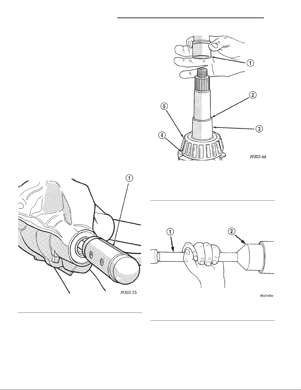
(5) Rotate the pinion shaft using a (in. lbs.) torque
wrench. Rotating torque should be equal to the reading recorded during removal, plus an additional 0.56
N·m (5 in. lbs.) (Fig. 9).
(6) If the rotating torque is low, use Holder 6958 to
hold the pinion yoke, and tighten the pinion shaft
nut in 6.8 N·m (5 ft. lbs.) increments until proper
rotating torque is achieved.
Fig. 8 Pinion Yoke Installation
1 – PINION YOKE
2 – AXLE HOUSING
Fig. 9 Check Pinion Rotation Torque
1 – PINION YOKE
2 – INCH POUND TORQUE WRENCH
(7) Align the installation reference marks on the
propeller shaft and yoke, and install the propeller
shaft.
(8) Check and fill the gear lubricant. Refer to the
Lubricant Specifications for gear lubricant requirements.
(9) Install the brake rotors and calipers. Refer to
Group 5, Brakes, for proper procedures.
(10) Install wheel and tire assemblies.
(11) Lower the vehicle.
Page 26
3 - 26 TUBE, 181, AND 186 FBI AXLE XJ
REMOVAL AND INSTALLATION (Continued)
186 FBI PINION SHAFT SEAL
REMOVAL
(1) Raise and support the vehicle.
(2) Remove wheel and tire assemblies.
(3) Remove brake rotors and calipers. Refer to
Group 5, Brakes, for proper procedures.
(4) Mark the propeller shaft and pinion yoke for
installation reference.
(5) Remove the propeller shaft from the yoke.
(6) Rotate the pinion gear three or four times.
(7) Measure the amount of torque necessary to
rotate the pinion gear with a (in. lbs.) dial-type
torque wrench. Record the torque reading for installation reference.
(8) Using Holder 6958 to hold the pinion yoke,
remove the pinion nut and washer.
(9) Use Remover C-452 and Wrench C-3281 to
remove the pinion yoke (Fig. 10).
1 – SPECIAL TOOL C-4171
2 – SPECIAL TOOL C-3972–A
Fig. 11 Pinion Seal Installation
Fig. 10 Pinion Yoke Removal
1 – SPECIAL TOOL C-3281
2 – YOKE
3 – SPECIAL TOOL C-452
(10) Use a suitable pry tool or a slide hammer
mounted screw to remove the pinion seal.
INSTALLATION
(1) Apply a light coating of gear lubricant on the
lip of pinion seal. Install seal with Installer C-3972-A
and Handle C-4171 (Fig. 11).
(2) Install yoke on the pinion gear with Installer
W-162–D, Cup 8109, and Holder 6958 (Fig. 12).
CAUTION: Do not exceed the minimum tightening
torque when installing the pinion yoke retaining nut
at this point. Damage to collapsible spacer or bearings may result.
Fig. 12 Pinion Yoke Installation
1 – PINION YOKE
2 – AXLE HOUSING
(3) Install the pinion washer and a new nut on the
pinion gear. Tighten the nut only enough to
remove the shaft end play.
(4) Rotate the pinion shaft using a (in. lbs.) torque
wrench. Rotating torque should be equal to the reading recorded during removal, plus an additional 0.56
N·m (5 in. lbs.) (Fig. 13).
(5) If the rotating torque is low, use Holder 6958 to
hold the pinion yoke (Fig. 14), and tighten the pinion
shaft nut in 6.8 N·m (5 ft. lbs.) increments until
proper rotating torque is achieved.
CAUTION: If the maximum tightening torque is
reached prior to reaching the required rotating
torque, the collapsible spacer may have been damaged. Replace the collapsible spacer.
(6) Align the installation reference marks on the
propeller shaft and yoke and install the propeller
shaft.
Page 27
XJ TUBE, 181, AND 186 FBI AXLE 3 - 27
REMOVAL AND INSTALLATION (Continued)
(8) Install the brake rotors and calipers. Refer to
Group 5, Brakes, for proper procedures.
(9) Install wheel and tire assemblies.
(10) Lower the vehicle.
COLLAPSIBLE SPACER
REMOVAL W/PINION INSTALLED
(1) Raise and support the vehicle.
(2) Remove wheel and tire assemblies.
(3) Remove brake rotors and calipers. Refer to
Group 5, Brakes, for proper procedures.
(4) Mark the propeller shaft and pinion yoke for
installation reference.
(5) Remove the propeller shaft from the yoke.
(6) Rotate the pinion gear three or four times.
(7) Measure the amount of torque necessary to
rotate the pinion gear with a (in. lbs.) dial-type
torque wrench. Record the torque reading for installation reference.
(8) Using Holder 6958 to hold the pinion yoke,
remove the pinion nut and washer.
Fig. 13 Check Pinion Rotation Torque
1 – PINION YOKE
2 – INCH POUND TORQUE WRENCH
(9) Use Remover C-452 and Wrench C-3281 to
remove the pinion yoke (Fig. 15).
(10) Use a suitable pry tool or a slide hammer
mounted screw, remove the pinion seal.
(11) Remove the front pinion bearing using a pair
of suitable pick tools to pull the bearing straight off
the pinion gear shaft. It may be necessary to lightly
tap the end of the pinion gear with a rawhide or rubber mallet if the bearing becomes bound on the pinion shaft.
(12) Remove the collapsible spacer.
Fig. 14 Tightening Pinion Shaft Nut—Typical
1 – PINION FLANGE
2 – FRONT AXLE
3 – TOOL 6958
(7) Check and fill the gear lubricant. Refer to the
Lubricant Specifications for gear lubricant requirements.
Fig. 15 Pinion Yoke Removal
1 – SPECIAL TOOL C-3281
2 – YOKE
3 – SPECIAL TOOL C-452
Page 28
3 - 28 TUBE, 181, AND 186 FBI AXLE XJ
REMOVAL AND INSTALLATION (Continued)
REMOVAL W/PINION REMOVED
(1) Raise and support the vehicle.
(2) Remove wheel and tire assemblies.
(3) Remove brake rotors and calipers. Refer to
Group 5, Brakes, for proper procedures.
(4) Mark the propeller shaft and pinion yoke for
installation reference.
(5) Remove the propeller shaft from the yoke.
(6) Rotate the pinion gear three or four times.
(7) Measure the amount of torque necessary to
rotate the pinion gear with a (in. lbs.) dial-type
torque wrench. Record the torque reading for installation reference.
(8) Remove differential assembly from axle housing.
(9) Using Holder 6958 to hold yoke, remove the
pinion nut and washer.
(10) Using Remover C-452 and Wrench C-3281,
remove the pinion yoke from pinion shaft (Fig. 15).
(11) Remove the pinion gear from housing (Fig.
16). Catch the pinion with your hand to prevent it
from falling and being damaged.
(12) Remove collapsible spacer from pinion shaft.
1 – COLLAPSIBLE SPACER
2 – SHOULDER
3 – PINION GEAR
4 – OIL SLINGER
5 – REAR BEARING
Fig. 17 Collapsible Preload Spacer
Fig. 16 Remove Pinion Gear
1 – RAWHIDE HAMMER
INSTALLATION
(1) Install a new collapsible preload spacer on pinion shaft (Fig. 17).
(2) If pinion gear was removed, install pinion gear
in housing.
(3) Install pinion front bearing, if necessary.
(4) Apply a light coating of gear lubricant on the
lip of pinion seal. Install seal with Installer C-3972-A
and Handle C-4171 (Fig. 18), if necessary.
Fig. 18 Pinion Seal Installation
1 – SPECIAL TOOL C-4171
2 – SPECIAL TOOL C-3972–A
(5) Install yoke with Installer W-162-D, Cup 8109,
and holder 6958 (Fig. 19).
(6) If the original pinion bearings are being used,
install differential assembly and axle shafts, if necessary.
Page 29
XJ TUBE, 181, AND 186 FBI AXLE 3 - 29
REMOVAL AND INSTALLATION (Continued)
Fig. 19 Pinion Yoke Installation
1 – PINION YOKE
2 – AXLE HOUSING
NOTE: If new pinion bearings were installed, do not
install the differential assembly and axle shafts until
after the pinion bearing preload and rotating torque
are set.
(7) Install the pinion washer and a new nut on the
pinion gear. Tighten the nut to 217 N·m (160 ft. lbs.)
minimum. Do not over-tighten. Maximum torque is
353 N·m (260 ft. lbs.).
1 – PINION FLANGE
2 – FRONT AXLE
3 – TOOL 6958
Fig. 20 Tightening Pinion Nut
CAUTION: Never loosen pinion gear nut to
decrease pinion gear bearing rotating torque and
never exceed specified preload torque. If preload
torque is exceeded, a new collapsible spacer must
be installed. The torque sequence will then have to
be repeated.
(8) Using yoke holder 6958 and a torque wrench
set at 353 N·m (260 ft. lbs.), crush collapsible spacer
until bearing end play is taken up (Fig. 20). If more
than 353 N·m (260 ft. lbs.) is needed to begin to collapse the spacer, the spacer is defective and must be
replaced.
(9) Slowly tighten the nut in 6.8 N·m (5 ft. lbs.)
increments until the rotating torque is achieved.
Measure the rotating torque frequently to avoid over
crushing the collapsible spacer (Fig. 21).
(10) Check rotating torque with an inch pound
torque wrench (Fig. 21). The torque necessary to
rotate the pinion gear should be:
• Original Bearings — The reading recorded dur-
ing removal, plus an additional 0.56 N·m (5 in. lbs.).
• New Bearings — 1.5 to 4 N·m (15 to 35 in. lbs.).
(11) Install differential assembly and axle shafts, if
necessary.
(12) Align marks made previously on yoke and
propeller shaft and install propeller shaft.
Fig. 21 Check Pinion Gear Rotation Torque—Typical
1 – PINION YOKE
2 – INCH POUND TORQUE WRENCH
(13) Install brake rotors and calipers. Refer to
Group 5, Brakes, for proper procedures.
Page 30
3 - 30 TUBE, 181, AND 186 FBI AXLE XJ
REMOVAL AND INSTALLATION (Continued)
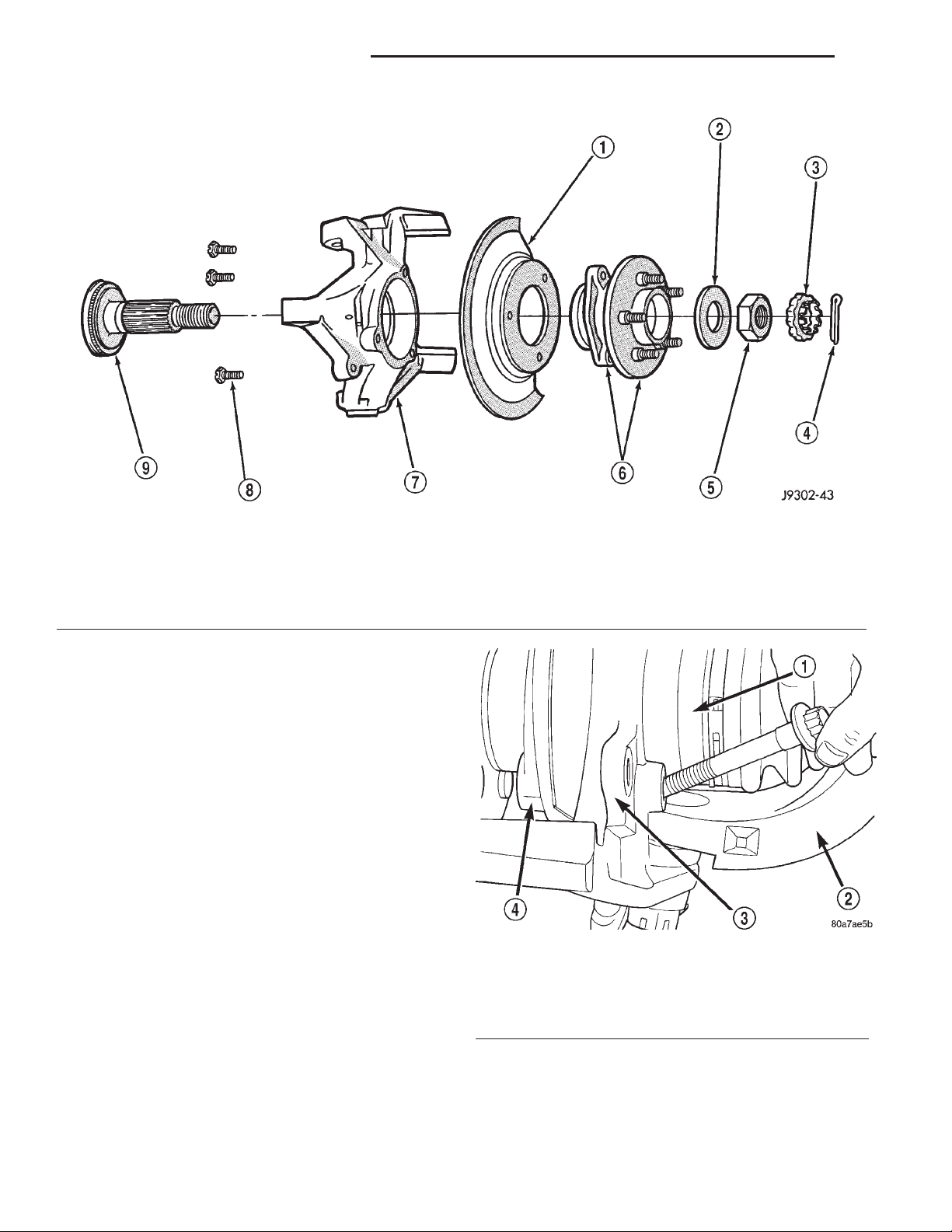
Fig. 22 Hub, Knuckle and Axle Shaft
1 – BRAKE SHIELD
2 – WASHER
3 – RETAINER
4 – COTTER PIN
5 – NUT
(14) Add gear lubricant, if necessary. Refer to
Lubricant Specifications of this section for lubricant
requirements.
(15) Install wheel and tire assemblies.
(16) Lower vehicle.
HUB BEARING AND AXLE SHAFT
If the axle shaft and hub bearing are being
removed in order to service another component, the
axle shaft and hub bearing can be removed as an
assembly.
REMOVAL
(1) Raise and support the vehicle.
(2) Remove the wheel and tire assembly.
(3) Remove the brake caliper and rotor. Refer to
Group 5, Brakes, for proper procedures.
(4) Remove ABS wheel speed sensor, if necessary.
Refer to Group 5, Brakes, for proper procedures.
(5) Remove the cotter pin, nut retainer, and axle
hub nut (Fig. 22), if necessary.
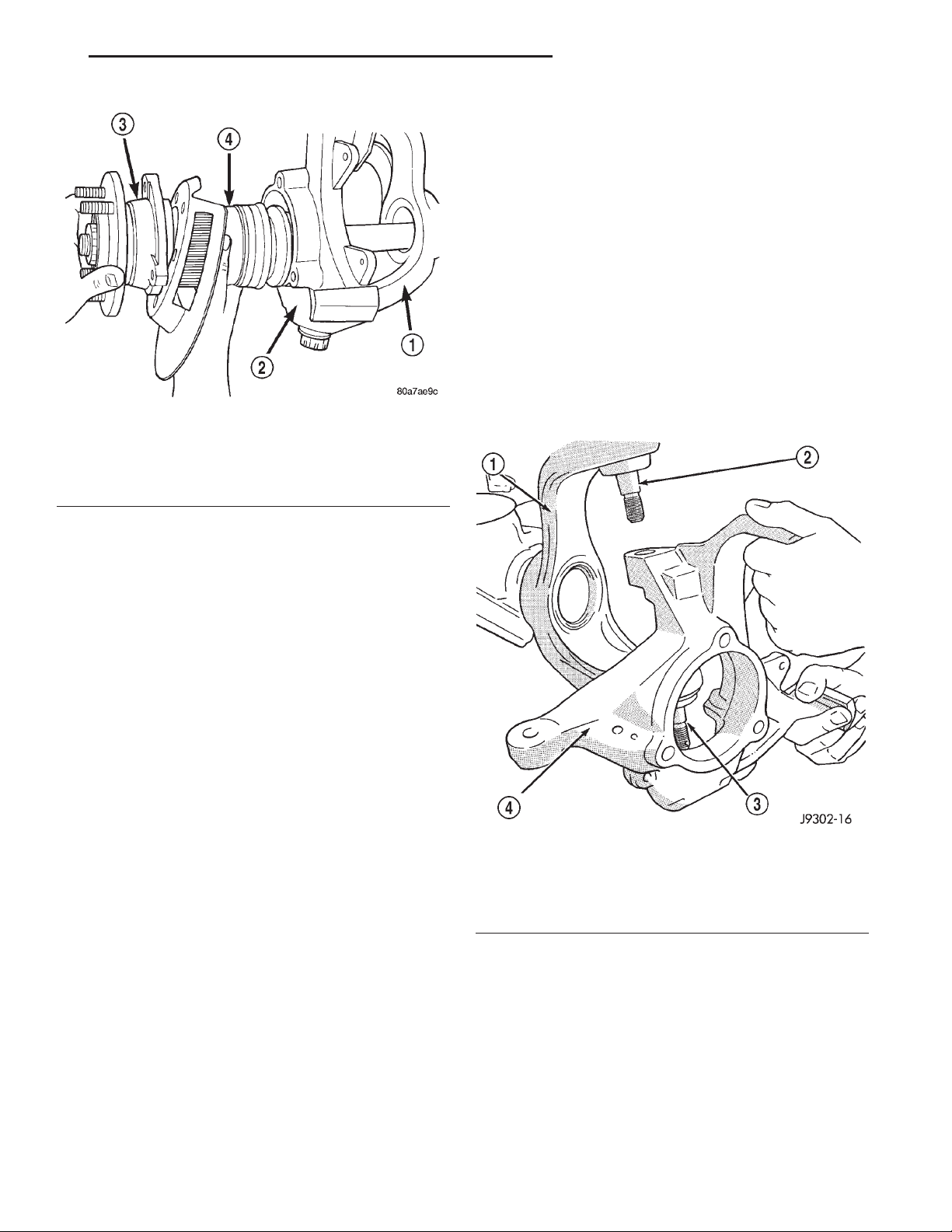
(6) Remove the hub to knuckle bolts (Fig. 23).
(7) Remove the hub from the steering knuckle and
axle shaft, if necessary.
(8) Remove hub bearing and axle shaft assembly
(Fig. 24), or axle shaft from axle. Avoid damaging
the axle shaft oil seals in the axle housing.
6 – HUB AND BEARING ASSEMBLY
7 – STEERING KNUCKLE
8 – BOLT
9 – TONE WHEEL (ABS)
Fig. 23 Hub Bearing Bolts
1 – AXLE SHAFT
2 – AXLE
3 – KNUCKLE
4 – HUB BEARING
(9) Remove the brake rotor shield from the hub
bearing or knuckle (Fig. 22).
Page 31
XJ TUBE, 181, AND 186 FBI AXLE 3 - 31
REMOVAL AND INSTALLATION (Continued)
STEERING KNUCKLE AND BALL STUDS
Ball stud service procedures below require removal
of the hub bearing and axle shaft. Removal and
installation of upper and lower ball studs require the
use of Tool Kit 6289.
KNUCKLE REMOVAL
(1) Remove hub bearing and axle shaft.
(2) Disconnect the tie-rod or drag link from the
steering knuckle arm. Refer to Group 2, Suspension,
for proper procedures.
(3) Remove the cotter pins from the upper and
lower ball studs.
(4) Remove the upper and lower ball stud nuts.
(5) Strike the steering knuckle with a brass hammer to loosen knuckle from the ball studs. Remove
Fig. 24 Hub Bearing and Axle Assembly
1 – AXLE
2 – KNUCKLE
3 – HUB BEARING
4 – AXLE SHAFT
knuckle from ball studs (Fig. 25).
INSTALLATION
(1) Thoroughly clean the axle shaft (Fig. 22) and
apply a thin film of Mopart Wheel Bearing Grease,
or equivalent, to the shaft splines, seal contact surface, and hub bore.
(2) Install the brake rotor shield to the knuckle.
(3) Install the hub bearing and axle shaft assembly, or axle shaft, into the housing and differential
side gears. Avoid damaging the axle shaft oil seals in
the axle housing.
(4) Install the hub bearing, if necessary.
(5) Install the hub to knuckle bolts and tighten to
102 N·m (75 ft. lbs.) torque.
(6) Install the hub washer and nut, if necessary.
Tighten the hub nut to 237 N·m (175 ft. lbs.) torque.
Install the nut retainer and a new cotter pin (Fig.
22).
(7) Install ABS wheel speed sensor, if necessary.
Refer to Group 5, Brakes, for proper procedures.
(8) Install the brake rotor and caliper. Refer to
Group 5, Brakes, for proper procedures.
(9) Install the wheel and tire assembly.
(10) Remove support and lower the vehicle.
Fig. 25 Steering Knuckle Removal/Installation
1 – AXLE YOKE
2 – UPPER BALL STUD
3 – LOWER BALL STUD
4 – STEERING KNUCKLE
Page 32
3 - 32 TUBE, 181, AND 186 FBI AXLE XJ
REMOVAL AND INSTALLATION (Continued)
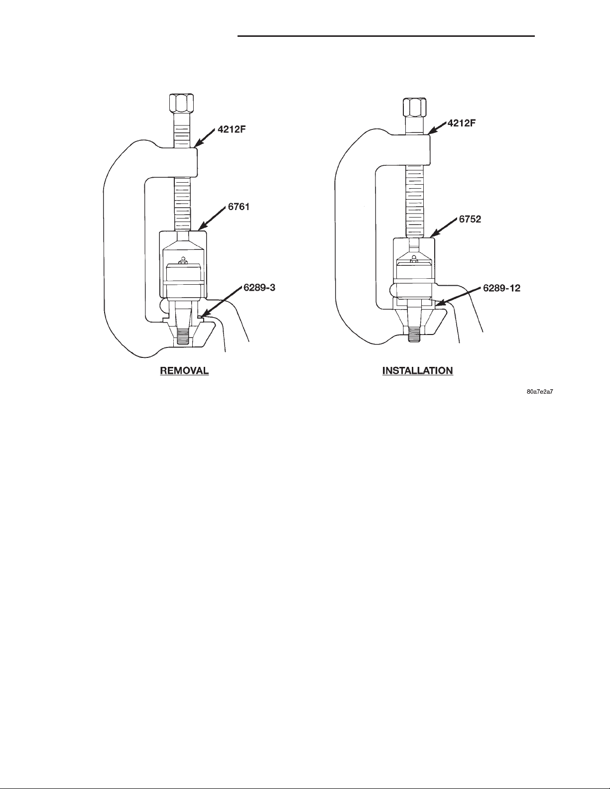
Fig. 26 Upper Ball Stud Remove/Install
UPPER BALL STUD REPLACEMENT
(1) Position tools as shown to remove and install
ball stud (Fig. 26).
LOWER BALL STUD REPLACEMENT
(1) Position tools as shown to remove and install
ball stud (Fig. 27).
KNUCKLE INSTALLATION
(1) Position the steering knuckle on the ball studs.
(2) Install and tighten the bottom retaining nut to
109 N·m (80 ft. lbs.) torque. Install new cotter pin.
(3) Install and tighten the top retaining nut to 101
N·m (75 ft. lbs.) torque. Install new cotter pin.
(4) Install the hub bearing and axle shaft.
(5) Connect the tie-rod or drag link end to the
steering knuckle arm. Refer to Group 2, Suspension,
for proper procedures.
Page 33
XJ TUBE, 181, AND 186 FBI AXLE 3 - 33
REMOVAL AND INSTALLATION (Continued)
Fig. 27 Lower Ball Stud Remove/Install
1 – SPECIAL TOOL 6289–12
2 – SPECIAL TOOL 6289–4
3 – SPECIAL TOOL 4212F
AXLE BUSHING REPLACEMENT
Refer to Group 2, Suspension, for the proper axle
bushing procedures.
DIFFERENTIAL
REMOVAL
(1) Raise and support vehicle.
(2) Remove the lubricant fill hole plug from the
differential housing cover.
(3) Remove the differential housing cover and
allow fluid to drain.
(4) Remove hub bearings and axle shafts.
(5) Note the installation reference letters stamped
on the bearing caps and housing machined sealing
surface (Fig. 28).
(6) Loosen the differential bearing cap bolts.
(7) Position Spreader W–129–B, utilizing some
items from Adapter Kit 6987, with the tool dowel
pins seated in the locating holes (Fig. 29). Install the
holddown clamps and tighten the tool turnbuckle finger–tight.
4 – SPECIAL TOOL 4212F
5 – SPECIAL TOOL 6289–1
6 – SPECIAL TOOL 6289–3
Fig. 28 Bearing Cap Identification
1 – INSTALLATION REFERENCE LETTERS
2 – INSTALLATION REFERENCE LETTERS
Page 34
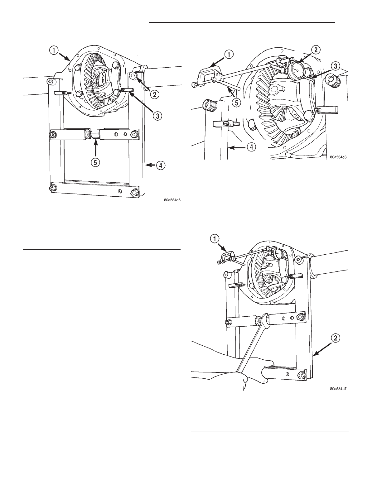
3 - 34 TUBE, 181, AND 186 FBI AXLE XJ
REMOVAL AND INSTALLATION (Continued)
Fig. 30 Install Dial Indicator
1 – SPECIAL TOOL
C-3339
2 – DIAL INDICATOR
3 – LEVER ADAPTER
Fig. 29 Install Axle Housing Spreader
1 – AXLE HOUSING
2 – DOWEL
3 – SAFETY HOLD DOWN
4 – SPECIAL TOOL
W-129–B
5 – TURNBUCKLE
4 – SPECIAL TOOL
W-129–B
5 – SPECIAL TOOL
C-3288–B
(8) Install a Guide Pin C-3288-B at the left side of
the differential housing. Attach Dial Indicator C-3339
to guide pin. Load the lever adapter against the
opposite side of the housing (Fig. 30) and zero the
indicator.
CAUTION: Do not spread over 0.50 mm (0.020 in). If
the housing is over-spread, it could be distorted or
damaged.
(9) Spread the housing enough to remove the differential case from the housing. Measure the distance with the dial indicator (Fig. 31).
(10) Remove the dial indicator.
(11) While holding the differential case in position,
remove the differential bearing cap bolts and caps.
(12) Remove the differential, and the differential
preload shims for the 181FBI axles, from the housing. Ensure that the differential bearing cups remain
in position on the differential bearings (Fig. 32).
(13) Mark or tag the differential bearing cups, and
the differential preload shims for the 181FBI axles,
to indicate which side of the differential they were
removed from.
(14) Remove spreader from housing.
Fig. 31 Spread Axle Housing
1 – SPECIAL TOOL
C-3339
2 – SPECIAL TOOL
W-129–B
Page 35
XJ TUBE, 181, AND 186 FBI AXLE 3 - 35
REMOVAL AND INSTALLATION (Continued)
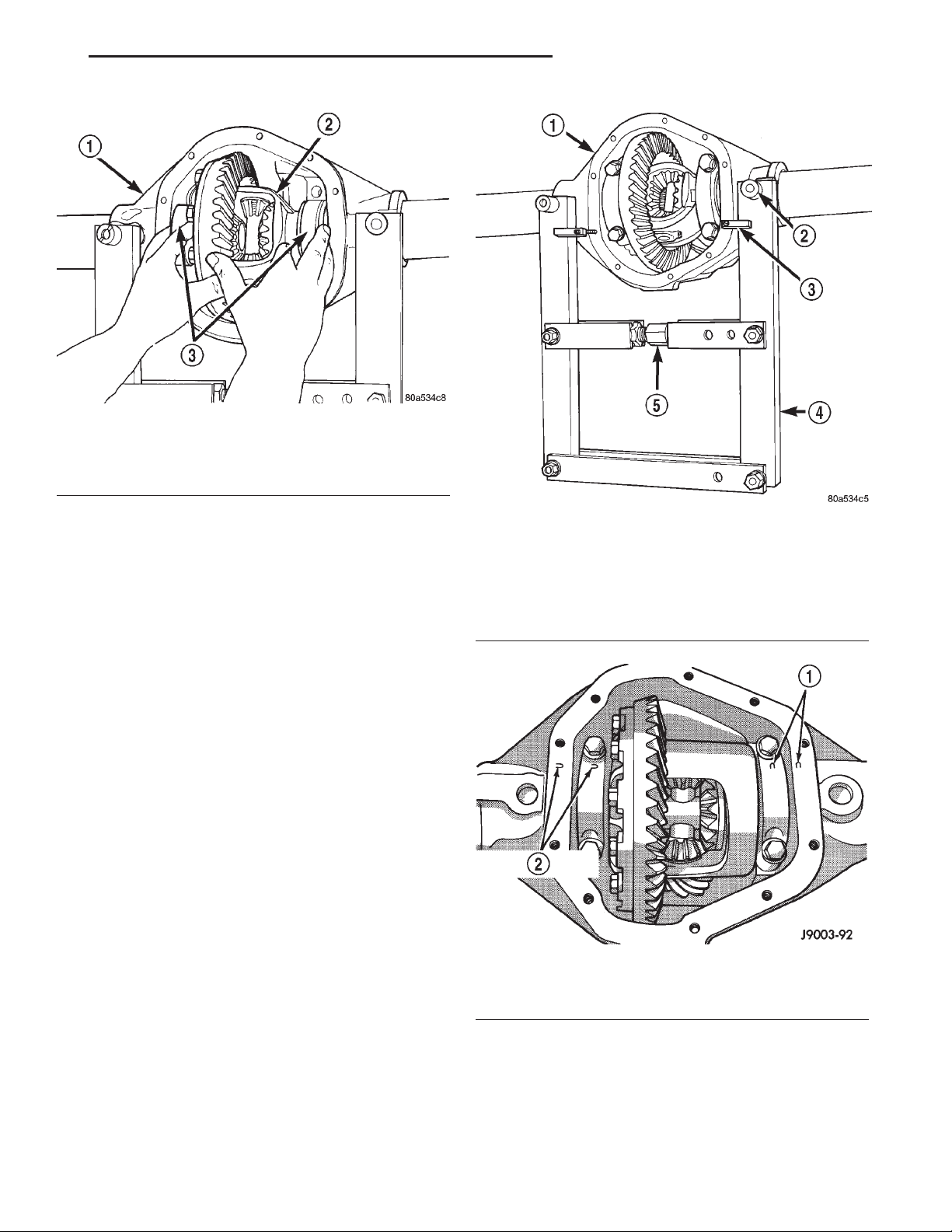
Fig. 32 Differential Case Removal
1 – AXLE HOUSING
2 – DIFFERENTIAL CASE
3 – BEARING CUPS
INSTALLATION
If replacement differential bearings or differential
case are being installed, differential side bearing
shim requirements may change. Refer to the Differential Bearing Preload and Gear Backlash procedures in this section to determine the proper shim
selection.
(1) Position Spreader W-129-B, utilizing some
items from Adapter Kit 6987, with the tool dowel
pins seated in the locating holes (Fig. 33). Install the
holddown clamps and tighten the tool turnbuckle finger–tight.
(2) Install a Guide Pin C-3288-B at the left side of
the differential housing. Attach Dial Indicator C-3339
to guide pin. Load the lever adapter against the
opposite side of the housing (Fig. 30) and zero the
indicator.
CAUTION: Do not spread over 0.50 mm (0.020 in). If
the housing is over-spread, it could be distorted or
damaged.
(3) Spread the housing enough to install the case
in the housing. Measure the distance with the dial
indicator (Fig. 31).
(4) Remove the dial indicator.
(5) Install differential case, and the differential
preload shims for the 181FBI axles, in the housing.
Ensure that the differential bearing cups remain in
position on the differential bearings. Tap the differential case to ensure the bearings cups are fully
seated in the housing.
(6) Install the bearing caps at their original locations (Fig. 34).
(7) Loosely install differential bearing cap bolts.
Fig. 33 Install Axle Housing Spreader
1 – AXLE HOUSING
2 – DOWEL
3 – SAFETY HOLD DOWN
4 – SPECIAL TOOL
W-129–B
5 – TURNBUCKLE
Fig. 34 Differential Bearing Cap Reference Letters
1 – INSTALLATION REFERENCE LETTERS
2 – INSTALLATION REFERENCE LETTERS
(8) Remove axle housing spreader.
(9) Tighten the bearing cap bolts to 61 N·m (45 ft.
lbs.) torque.
(10) Install the hub bearings and axle shafts.
Page 36
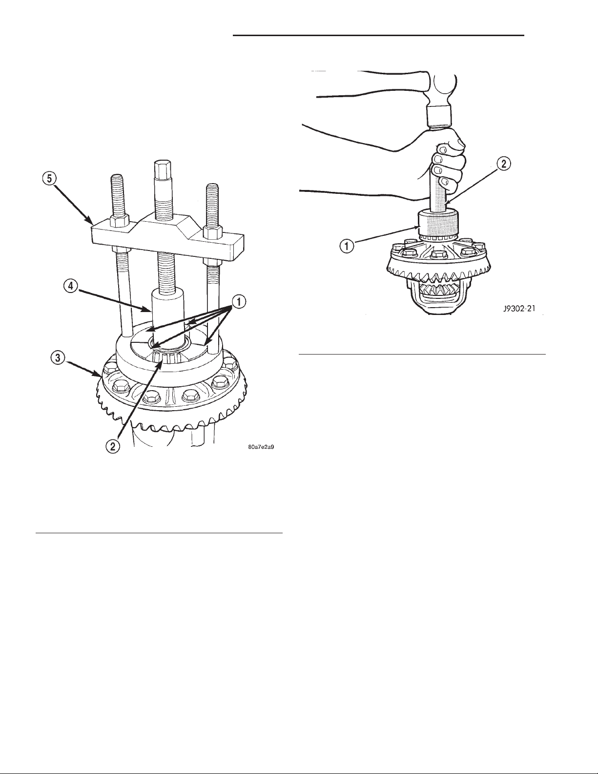
3 - 36 TUBE, 181, AND 186 FBI AXLE XJ
REMOVAL AND INSTALLATION (Continued)
DIFFERENTIAL SIDE BEARINGS
REMOVAL
(1) Remove differential case from axle housing.
(2) Remove the bearings from the differential case
with Puller/Press C-293-PA, C-293-39 Adapter
Blocks, and Plug SP-3289 (Fig. 35).
Fig. 35 Differential Bearing Removal
1 – SPECIAL TOOL C–293–39
2 – BEARING
3 – DIFFERENTIAL
4 – SPECIAL TOOL SP–3289
5 – SPECIAL TOOL C–293–PA
INSTALLATION
If replacement differential side bearings or differential case are being installed, differential side bearing shim requirements may change. Refer to the
Differential Bearing Preload and Gear Backlash procedures in this section to determine the proper shim
selection.
(1) Install differential side bearing shims onto differential case hubs, for 186FBI axles.
(2) Using Installer C-3716-A and Handle C-4171,
install differential side bearings (Fig. 36).
(3) Install differential in axle housing.
Fig. 36 Differential Side Bearing Installation
1 – SPECIAL TOOL C-3716–A
2 – SPECIAL TOOL C-4171
AXLE SHAFT OIL SEAL
REMOVAL
(1) Raise and support vehicle.
(2) Remove differential assembly.
(3) Remove the inner axle shaft seals with a pry
bay.
INSTALLATION
(1) Remove any sealer remaining from original
seals.
(2) Remove sealer from axle tube to housing junc-
tion, if necessary.
(3) Install oil seals with Discs 8110 and Turnbuckle 6797 (Fig. 37). Tighten tool until disc bottoms
in housing.
(4) Install differential assembly.
181 FBI PINION
The ring gear and pinion are serviced as a matched
set. Do not replace the pinion without replacing the
ring gear.
REMOVAL
(1) Remove differential assembly from axle housing.
(2) Mark pinion yoke and propeller shaft for
installation alignment.
(3) Disconnect propeller shaft from pinion yoke.
Using suitable wire, tie propeller shaft to underbody.
Page 37
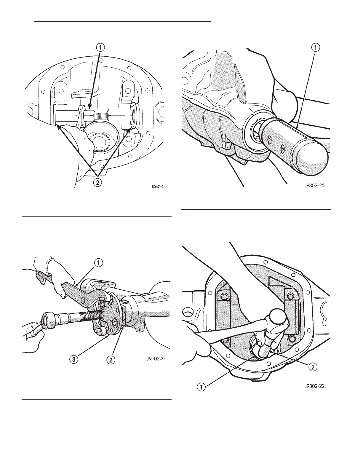
XJ TUBE, 181, AND 186 FBI AXLE 3 - 37
REMOVAL AND INSTALLATION (Continued)
Fig. 37 Axle Seal Installation
1 – TURNBUCKLE 6797
2 – DISCS 8110
(4) Using Holder 6958 to hold yoke, remove the
pinion nut and washer.
(5) Using Remover C-452 and Holder C-3281,
remove the pinion yoke from pinion shaft (Fig. 38).
Fig. 39 Remove Pinion Gear
1 – RAWHIDE HAMMER
(7) Remove the front pinion bearing cup, bearing,
oil slinger, if equipped, and pinion seal with Remover
D-147 and Handle C–4171 (Fig. 40).
Fig. 38 Pinion Yoke Removal
1 – SPECIAL TOOL C-3281
2 – YOKE
3 – SPECIAL TOOL C-452
(6) Remove the pinion gear and preload shims
from housing (Fig. 39). Catch the pinion with your
hand to prevent it from falling and being damaged.
Fig. 40 Front Bearing Cup Removal
1 – REMOVER
2 – HANDLE
Page 38
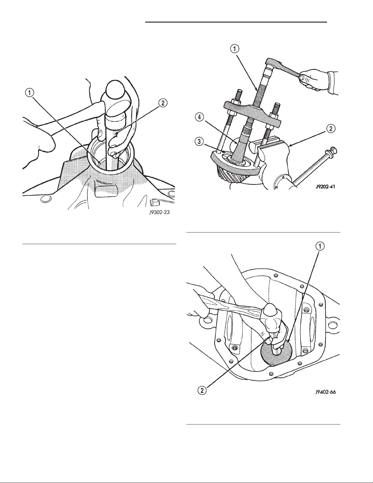
3 - 38 TUBE, 181, AND 186 FBI AXLE XJ
REMOVAL AND INSTALLATION (Continued)
(8) Remove the rear pinion bearing cup and oil
slinger from the axle housing (Fig. 41). Use Remover
D-149 and Handle C–4171. Record the thickness of
the oil slinger for future reference.
Fig. 41 Rear Bearing Cup Removal
1 – DRIVER
2 – HANDLE
(9) Remove the rear pinion bearing from the pinion with Puller/Press C–293-PA and Adapters
C-293-39 (Fig. 42).
Place 4 adapter blocks so they do not damage
the bearing cage.
(10) Remove the pinion depth shim/oil baffle from
the pinion shaft. Record the thickness of the depth
shim/oil baffle.
INSTALLATION
NOTE: A pinion depth shim/oil baffle is placed
between the rear pinion bearing cone and pinion
gear. If the factory installed ring and pinion gears
are reused, the pinion depth shim/oil baffle should
not require replacement. Refer to Pinion Gear Depth
to select the proper thickness shim before installing
pinion gear.
Fig. 42 Rear Bearing Removal
1 – SPECIAL TOOL C-293–PA
2 – VISE
3 – ADAPTERS
4 – DRIVE PINION GEAR SHAFT
(1) Install a new oil slinger of the same thickness
as the original into the rear pinion bearing bore of
the axle housing.
(2) Apply Mopart Door Ease, or equivalent, stick
lubricant to outside surface of rear pinion bearing
cup. Install the bearing cup with Installer D-146 and
Handle C–4171 (Fig. 43). Verify cup is correctly
seated.
Fig. 43 Rear Pinion Bearing Cup Installation
1 – INSTALLER
2 – HANDLE
Page 39
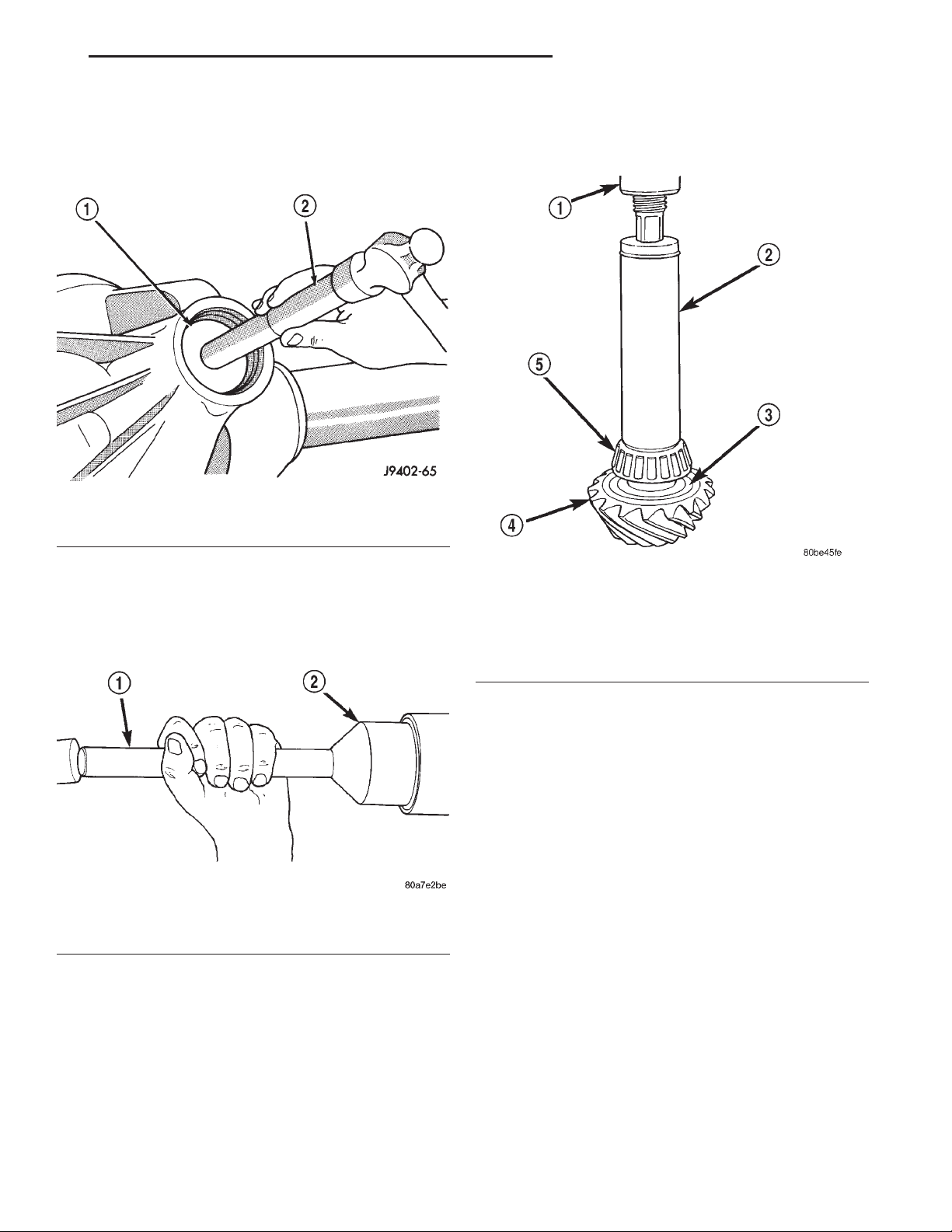
XJ TUBE, 181, AND 186 FBI AXLE 3 - 39
REMOVAL AND INSTALLATION (Continued)
(3) Apply Mopart Door Ease, or equivalent, stick
lubricant to outside surface of front pinion bearing
cup. Install the bearing cup with Installer D-144 and
Handle C–4171 (Fig. 44).
Fig. 44 Pinion Outer Bearing Cup Installation
1 – INSTALLER
2 – HANDLE
(6) Install the rear pinion bearing and pinion
depth shim/oil baffle onto the pinion gear with
Installer W-262 and a shop press (Fig. 46).
(4) Install front pinion bearing, and oil slinger, if
equipped.
(5) Apply a light coating of gear lubricant on the
lip of pinion seal. Install seal with Installer C-3972-A
and Handle C–4171 (Fig. 45).
Fig. 45 Pinion Seal Installation
1 – SPECIAL TOOL C-4171
2 – SPECIAL TOOL C-3972–A
Fig. 46 Rear Pinion Bearing Installation
1 – PRESS
2 – INSTALLATION TOOL
3 – PINION DEPTH SHIM/OIL BAFFLE
4 – DRIVE PINION
5 – DRIVE PINION SHAFT REAR BEARING
(7) Install pinion bearing preload shims onto the
pinion gear (Fig. 47).
(8) Install pinion gear in housing.
(9) Install yoke with Installer W-162-B, Cup 8109,
and Holder 6958 (Fig. 48).
Page 40
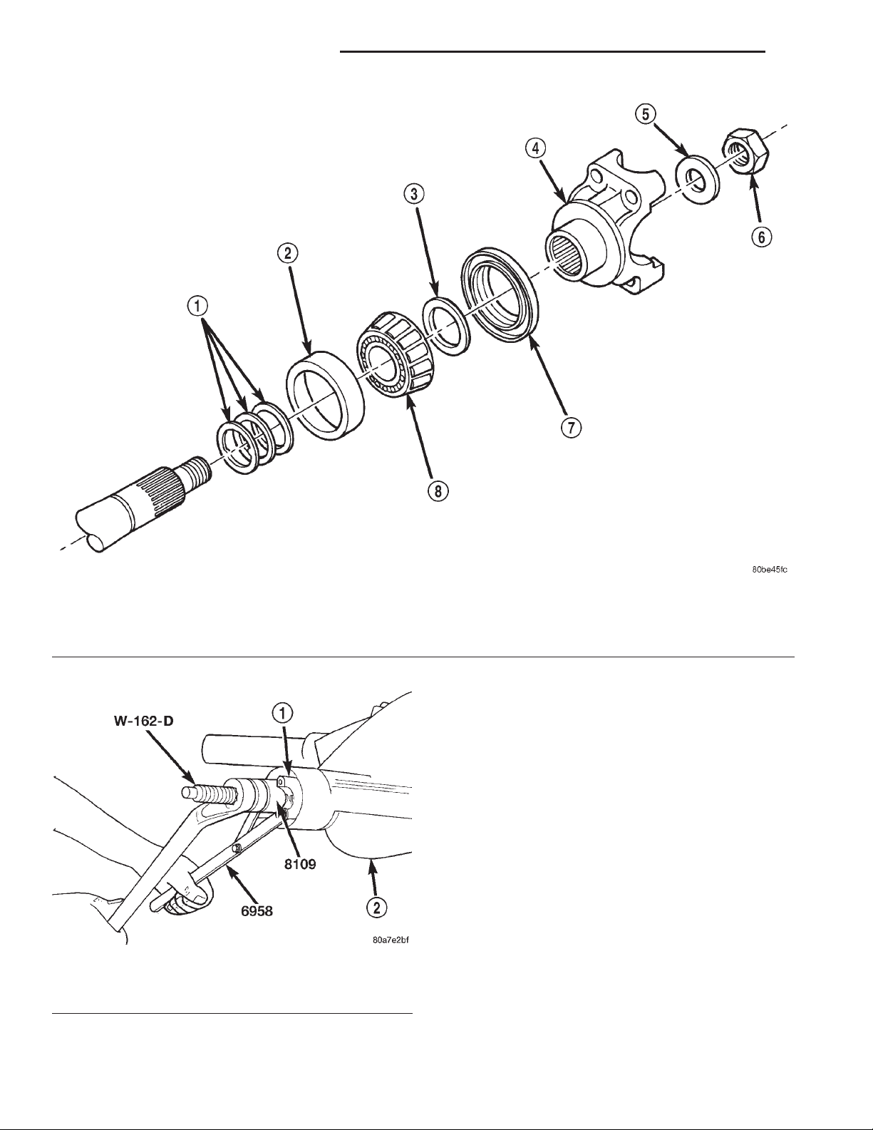
3 - 40 TUBE, 181, AND 186 FBI AXLE XJ
REMOVAL AND INSTALLATION (Continued)
1 – PINION PRELOAD SHIMS
2 – FRONT BEARING CUP
3 – SLINGER
4 – PINION YOKE
Fig. 48 Pinion Yoke Installation
1 – PINION YOKE
2 – AXLE HOUSING
Fig. 47 Pinion Preload Shims–Typical
5 – WASHER
6 – PINION NUT
7 – PINION OIL SEAL
8 – FRONT BEARING CONE
(10) Install the pinion washer and a new nut on
the pinion gear. Tighten the nut to 217 N·m (160 ft.
lbs.).
CAUTION: Never loosen pinion gear nut to
decrease pinion gear bearing rotating torque and
never exceed specified preload rotating torque.
(11) Check bearing preload torque with an inch
pound torque wrench (Fig. 49). The torque necessary
to rotate the pinion gear should be:
• Original Bearings—1 to 2 N·m (10 to 20 in. lbs.).
• New Bearings—1.5 to 4 N·m (15 to 35 in. lbs.).
(12) If rotating torque is above the desired
amount, remove the pinion yoke and increase the
preload shim pack thickness. Increasing the shim
pack thickness 0.025 mm (0.001 in.) will decrease the
rotating torque approximately 0.9 N·m (8 in. lbs.).
(13) Tighten pinion shaft nut in 6.8 N·m (5 ft. lbs.)
increments until the maximum tightening or desired
rotating torque is reached. Maximum tightening
torque is 271 N·m (200 ft.lbs.).
Page 41
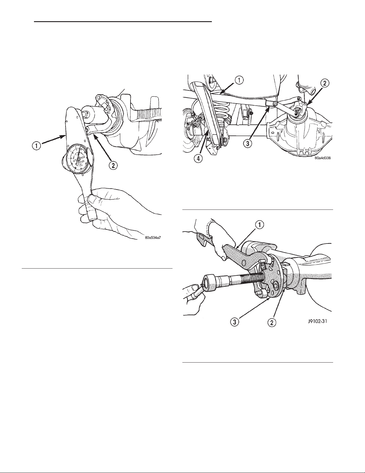
XJ TUBE, 181, AND 186 FBI AXLE 3 - 41
REMOVAL AND INSTALLATION (Continued)
(14) If the maximum tightening torque is reached
prior to achieving the desired rotating torque, remove
the pinion yoke and decrease the thickness of the
preload shim pack. Decreasing the shim pack thickness 0.025 mm (0.001 in.) will increase the rotating
torque approximately 0.9 N·m (8 in. lbs.).
(4) Using Holder 6958 to the hold yoke, remove
the pinion nut and washer (Fig. 50).
(5) Using Remover C–452 and Holder C-3281,
remove the pinion yoke from pinion shaft (Fig. 51).
Fig. 50 Pinion Yoke Holder—Typical
1 – 1 in. PIPE
2 – PINION YOKE
3 – SPECIAL TOOL
6958
4 – LOWER CONTROL ARM
Fig. 49 Check Pinion Gear Rotating Torque
1 – in. lbs. TORQUE WRENCH
2 – PINION YOKE
(15) Install differential assembly.
186 FBI PINION
The ring gear and pinion are serviced as a matched
set. Do not replace the pinion without replacing the
ring gear.
REMOVAL
(1) Remove differential assembly from axle housing.
(2) Mark pinion yoke and propeller shaft for
installation alignment.
(3) Disconnect propeller shaft from pinion yoke.
Using suitable wire, tie propeller shaft to underbody.
Fig. 51 Pinion Yoke Removal
1 – SPECIAL TOOL C-3281
2 – YOKE
3 – SPECIAL TOOL C-452
Page 42
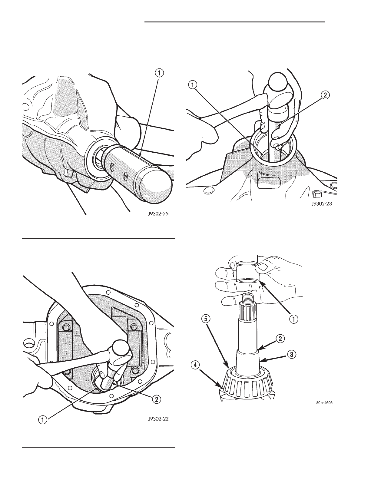
3 - 42 TUBE, 181, AND 186 FBI AXLE XJ
REMOVAL AND INSTALLATION (Continued)
(6) Remove the pinion and collapsible spacer from
housing (Fig. 52). Catch the pinion with your hand to
prevent it from falling and being damaged.
Fig. 52 Remove Pinion
1 – RAWHIDE HAMMER
(7) Remove the front pinion bearing cup, bearing,
oil slinger, if equipped, and pinion seal with Remover
C-4345 and Handle C–4171 (Fig. 53).
(8) Remove the rear pinion bearing cup from axle
housing (Fig. 54). Use Remover D-149 and Handle
C–4171.
Fig. 54 Rear Bearing Cup Removal
1 – DRIVER
2 – HANDLE
(9) Remove the collapsible preload spacer from
pinion gear (Fig. 55).
Fig. 53 Front Bearing Cup Removal
1 – REMOVER
2 – HANDLE
Fig. 55 Collapsible Spacer
1 – COLLAPSIBLE SPACER
2 – SHOULDER
3 – PINION
4 – PINION DEPTH SHIM
5 – REAR BEARING
Page 43
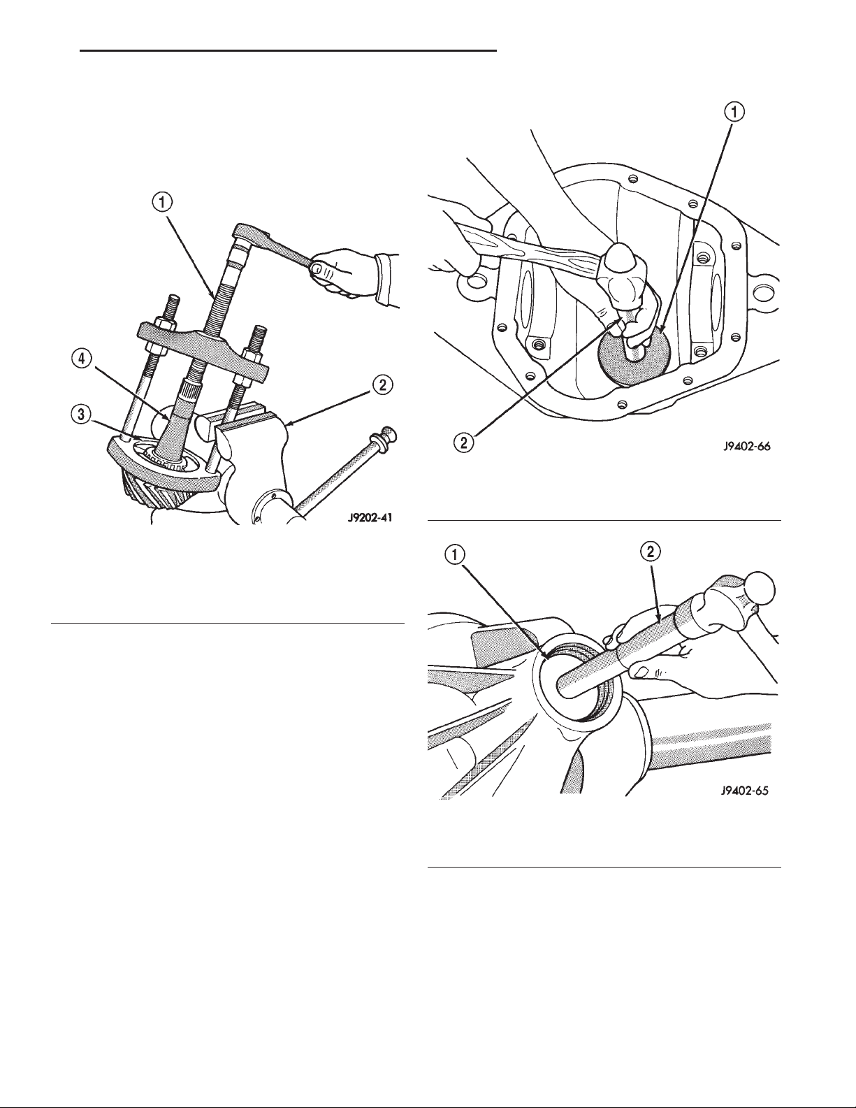
XJ TUBE, 181, AND 186 FBI AXLE 3 - 43
REMOVAL AND INSTALLATION (Continued)
(10) Remove the rear pinion bearing from the pinion with Puller/Press C–293-PA and Adapters
C–293–39 (Fig. 56).
Place 4 adapter blocks so they do not damage
the bearing cage.
Fig. 56 Inner Bearing Removal
1 – SPECIAL TOOL C-293–PA
2 – VISE
3 – ADAPTERS
4 – DRIVE PINION GEAR SHAFT
(11) Remove the depth shim/oil slinger from the
pinion shaft. Record the thickness of the depth shim/
oil slinger.
INSTALLATION
NOTE: A pinion depth shim/oil slinger is placed
between the rear pinion bearing cone and the pinion head to achieve proper ring gear and pinion
mesh. If the factory installed ring gear and pinion
are reused, the pinion depth shim/oil slinger should
not require replacement. Refer to Pinion Gear Depth
to select the proper thickness shim/oil slinger
before installing pinion.
Fig. 57 Rear Pinion Bearing Cup Installation
1 – INSTALLER
2 – HANDLE
Fig. 58 Pinion Outer Bearing Cup Installation
1 – INSTALLER
2 – HANDLE
(1) Apply Mopart Door Ease, or equivalent, stick
lubricant to outside surface of rear pinion bearing
cup. Install the bearing cup with Installer D-146 and
Driver Handle C–4171 (Fig. 57). Verify cup is correctly seated.
(2) Apply Mopart Door Ease, or equivalent, stick
lubricant to outside surface of front pinion bearing
cup. Install the bearing cup with Installer D-130 and
Handle C–4171 (Fig. 58).
(3) Install front pinion bearing, and oil slinger, if
equipped.
(4) Apply a light coating of gear lubricant on the
lip of pinion seal. Install seal with Installer C-3972-A
and Handle C–4171 (Fig. 59).
(5) Install the rear pinion bearing and the pinion
depth shim/oil slinger onto the pinion with Installer
W-262 and a shop press (Fig. 60).
Page 44
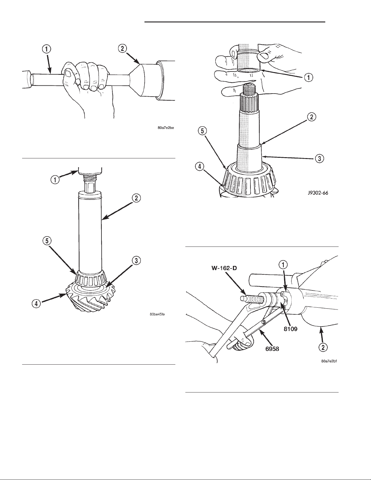
3 - 44 TUBE, 181, AND 186 FBI AXLE XJ
REMOVAL AND INSTALLATION (Continued)
Fig. 59 Pinion Seal Installation
1 – SPECIAL TOOL C-4171
2 – SPECIAL TOOL C-3972–A
Fig. 60 Rear Pinion Bearing Installation
1 – PRESS
2 – INSTALLATION TOOL
3 – PINION DEPTH SHIM/OIL BAFFLE
4 – DRIVE PINION
5 – DRIVE PINION SHAFT REAR BEARING
(6) Install a new collapsible preload spacer on pin-
ion shaft and install pinion in housing (Fig. 61).
(7) Install yoke with Installer W-162-B, Cup 8109,
and Holder 6958 (Fig. 62).
(8) Install the pinion washer and a new nut onto
the pinion. Tighten the nut to 216 N·m (160 ft. lbs.)
minimum. Do not over–tighten. Maximum torque
is 352 N·m (260 ft. lbs.).
Fig. 61 Collapsible Preload Spacer
1 – COLLAPSIBLE SPACER
2 – SHOULDER
3 – PINION GEAR
4 – OIL SLINGER
5 – REAR BEARING
Fig. 62 Pinion Yoke Installation
1 – PINION YOKE
2 – AXLE HOUSING
specified preload torque. If preload torque is
exceeded a new collapsible spacer must be
installed. The torque sequence will then have to be
repeated.
CAUTION: Never loosen the pinion nut to decrease
pinion bearing rotating torque and never exceed
(9) Using Holder 6958 and torque wrench (set at
352 N·m (260 ft. lbs.)), crush collapsible spacer until
Page 45
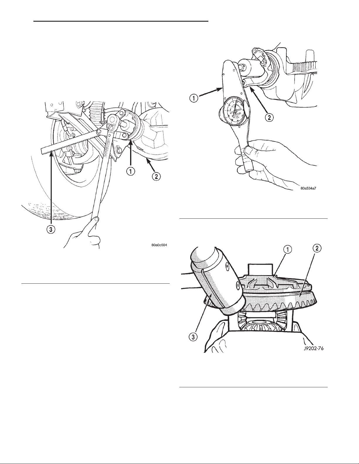
XJ TUBE, 181, AND 186 FBI AXLE 3 - 45
REMOVAL AND INSTALLATION (Continued)
bearing end play is taken up (Fig. 63). If more than
353 N·m (260 ft. lbs.) is needed to begin to collapse
the spacer, the spacer is defective and must be
replaced.
(10) Slowly tighten the nut in 6.8 N·m (5 ft. lb.)
increments until the rotating torque is achieved.
Measure the rotating torque frequently to avoid over
crushing the collapsible spacer (Fig. 64).
Fig. 63 Tightening Pinion Nut—Typical
1 – PINION FLANGE
2 – FRONT AXLE
3 – TOOL 6958
(11) Check bearing rotating torque with an inch
pound torque wrench (Fig. 64). The torque necessary
to rotate the pinion should be:
• Original Bearings—1to2N·m(10to20in.
lbs.).
• New Bearings — 1.5 to 4 N·m (15 to 35 in. lbs.).
(12) Install differential assembly.
RING GEAR
NOTE: The ring gear and pinion are serviced as a
matched set. Do not replace the ring gear without
replacing the pinion.
Fig. 64 Check Pinion Rotation Torque
1 – in. lbs. TORQUE WRENCH
2 – PINION YOKE
(4) Using a soft hammer, drive ring gear from dif-
ferential case (Fig. 65).
Fig. 65 Ring Gear Removal
1 – CASE
2 – RING GEAR
3 – RAWHIDE HAMMER
REMOVAL
(1) Remove differential from axle housing.
(2) Place differential case in a suitable vise with
soft metal jaw protectors. (Fig. 65)
(3) Remove bolts holding ring gear to differential
case.
INSTALLATION
CAUTION: Do not reuse the bolts that held the ring
gear to the differential case. The bolts can fracture
causing extensive damage.
Page 46
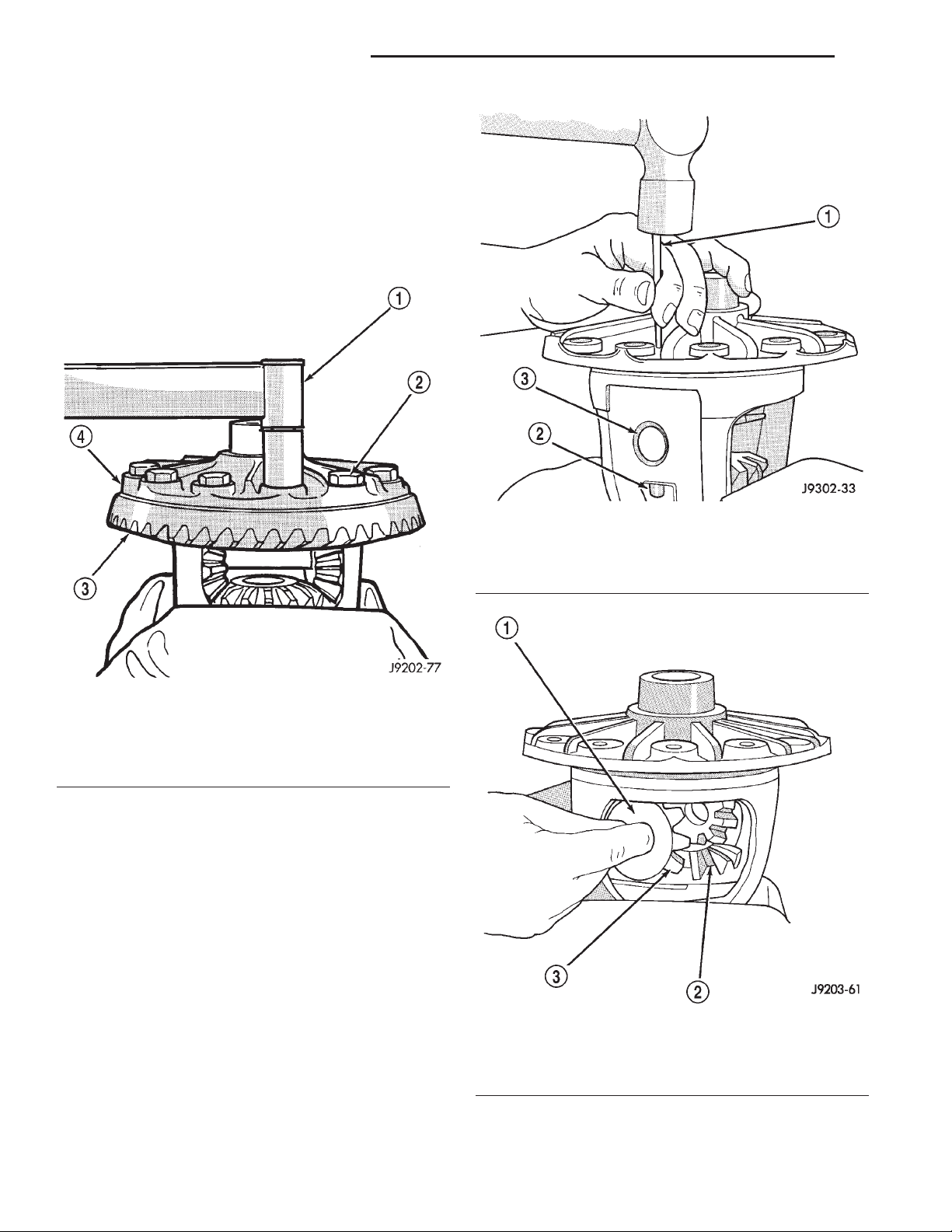
3 - 46 TUBE, 181, AND 186 FBI AXLE XJ
REMOVAL AND INSTALLATION (Continued)
(1) Invert the differential case and start two ring
gear bolts. This will provide case-to-ring gear bolt
hole alignment.
(2) Invert the differential case in the vise.
(3) Install new ring gear bolts and alternately
tighten to 95–122 N·m (70–90 ft. lbs.) torque (Fig.
66).
(4) Install differential in axle housing and verify
gear mesh and contact pattern.
Fig. 66 Ring Gear Bolt Installation
1 – TORQUE WRENCH
2 – RING GEAR BOLT
3 – RING GEAR
4 – CASE
DISASSEMBLY AND ASSEMBLY
STANDARD DIFFERENTIAL
DISASSEMBLY
(1) Remove the ring gear.
(2) Using a suitable roll pin punch, drive out the
roll pin holding pinion gear mate shaft in the differential case (Fig. 67).
(3) Remove the pinion gear mate shaft from the
differential case and the pinion mate gears.
(4) Rotate differential side gears and remove the
pinion mate gears and thrust washers (Fig. 68).
(5) Remove the differential side gears and thrust
washers.
Fig. 67 Mate Shaft Roll Pin Removal
1 – DRIFT
2 – LOCKPIN
3 – MATE SHAFT
Fig. 68 Pinion Mate Gear Removal
1 – THRUST WASHER
2 – SIDE GEAR
3 – PINION MATE GEAR
ASSEMBLY
(1) Install the differential side gears and thrust
washers.
(2) Install the pinion mate gears and thrust wash-
ers.
Page 47
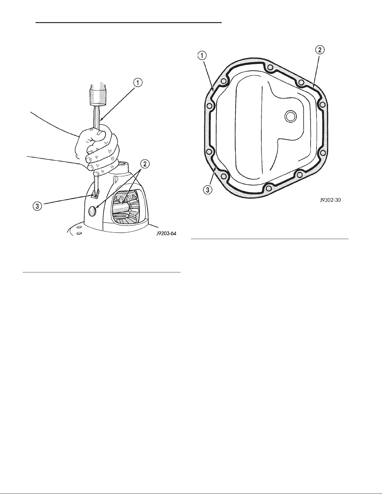
XJ TUBE, 181, AND 186 FBI AXLE 3 - 47
DISASSEMBLY AND ASSEMBLY (Continued)
(3) Install the pinion gear mate shaft. Align the
roll pin holes in shaft and the differential case.
(4) Install the roll pin to hold the pinion mate
shaft in the differential case (Fig. 69).
Fig. 69 Mate Shaft Roll Pin Installation
1 – PUNCH
2 – PINION MATE SHAFT
3 – MATE SHAFT LOCKPIN
(5) Install the ring gear.
(6) Lubricate all differential components with
hypoid gear lubricant.
FINAL ASSEMBLY
(1) Scrape the residual sealant from the housing
and cover mating surfaces. Clean the mating surfaces
with mineral spirits. Apply a bead of Mopart Silicone
Rubber Sealant, or equivalent, on the housing cover
(Fig. 70).
Install the housing cover within 5 minutes
after applying the sealant.
(2) Install the cover on the differential with the
attaching bolts. Install the identification tag. Tighten
the cover bolts to 41 N·m (30 ft. lbs.) torque.
CAUTION: Overfilling the differential can result in
lubricant foaming and overheating.
(3) Refill the differential housing with gear lubricant. Refer to the Lubricant Specifications section of
this group for the gear lubricant requirements.
(4) Install the fill hole plug.
Fig. 70 Typical Housing Cover With Sealant
1 – SEALING SURFACE
2 – CONTOUR OF BEAD
3 – BEAD THICKNESS 6.35mm (1/4”)
CLEANING AND INSPECTION
CARDAN U-JOINT
Clean all the U–joint yoke bores with cleaning solvent and a wire brush. Ensure that all the rust and
foreign matter are removed from the bores.
Inspect the yokes for distortion, cracks and worn
bearing cap bores.
Replace the complete U–joint if any of the components are defective.
AXLE COMPONENTS
Wash differential components with cleaning solvent
and dry with compressed air. Do not steam clean
the differential components.
Wash bearings with solvent and towel dry, or dry
with compressed air. DO NOT spin bearings with
compressed air. Cup and bearing must be
replaced as matched sets only.
Clean axle shaft tubes and oil channels in housing.
Inspect for;
• Smooth appearance with no broken/dented surfaces on the bearing rollers or the roller contact surfaces.
• Bearing cups must not be distorted or cracked.
• Machined surfaces should be smooth and with-
out any raised edges.
• Raised metal on shoulders of cup bores should
be removed with a hand stone.
Page 48
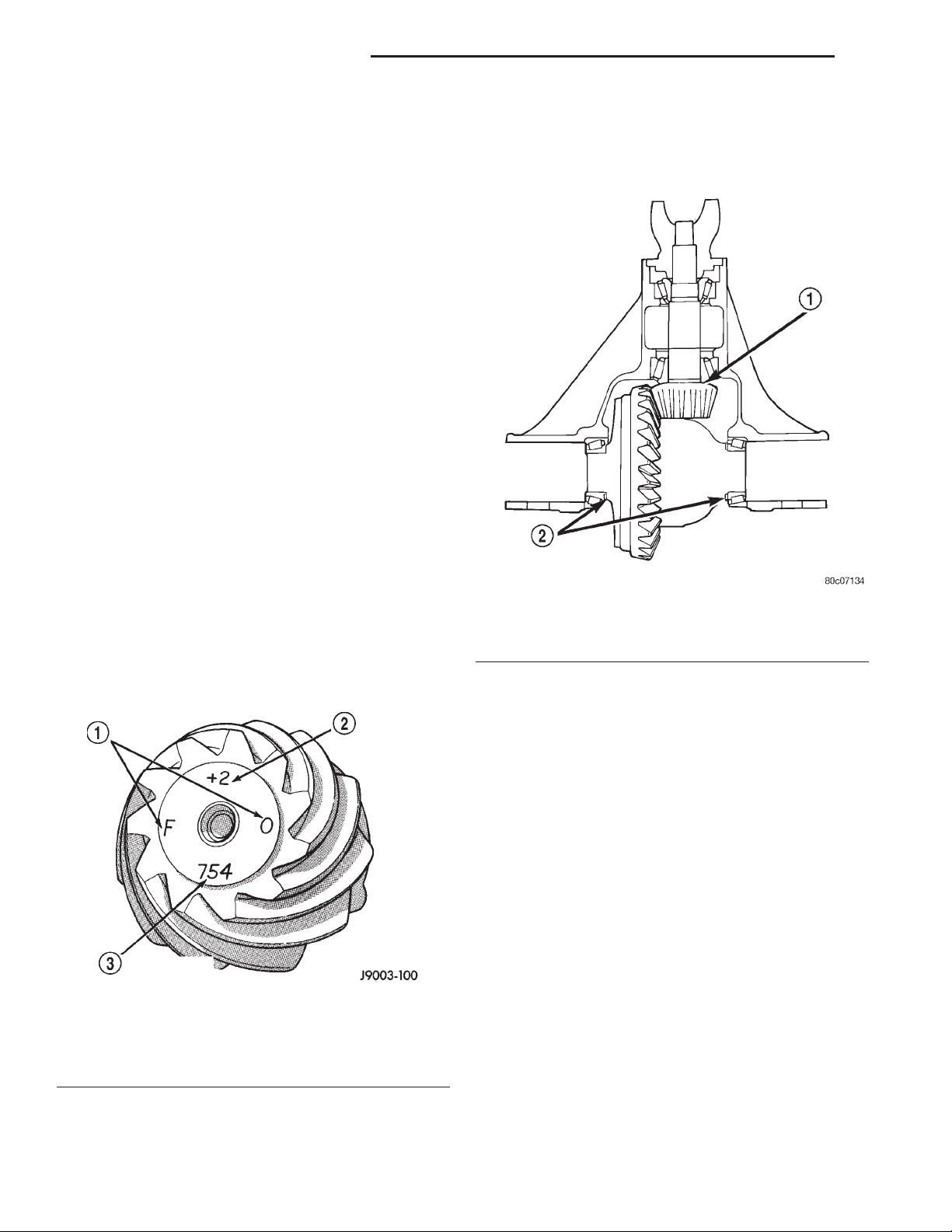
3 - 48 TUBE, 181, AND 186 FBI AXLE XJ
CLEANING AND INSPECTION (Continued)
• Wear and damage to pinion gear mate shaft,
pinion gears, side gears and thrust washers. Replace
as a matched set only.
• Ring and pinion gear for worn and chipped
teeth.
• Ring gear for damaged bolt threads. Replaced as
a matched set only.
• Pinion yoke for cracks, worn splines, pitted
areas, and a rough/corroded seal contact surface.
Repair or replace as necessary.
• Preload shims for damage and distortion. Install
new shims, if necessary.
ADJUSTMENTS
181 FBI PINION GEAR DEPTH
GENERAL INFORMATION
Ring and pinion gears are supplied as matched
sets only. The identifying numbers for the ring and
pinion gear are etched into the face of each gear (Fig.
71). A plus (+) number, minus (–) number or zero (0)
is etched into the face of the pinion gear. This number is the amount (in thousandths of an inch) the
depth varies from the standard depth setting of a
pinion etched with a (0). The standard setting from
the center line of the ring gear to the back face of the
pinion is 92.08 mm (3.625 in.). The standard depth
provides the best gear tooth contact pattern. Refer to
Backlash and Contact Pattern Analysis paragraph in
this section for additional information.
Fig. 71 Pinion Gear ID Numbers
1 – PRODUCTION NUMBERS
2 – DRIVE PINION GEAR DEPTH VARIANCE
3 – GEAR MATCHING NUMBER (SAME AS RING GEAR
NUMBER)
Compensation for pinion depth variance is
achieved with a select shim/oil baffle. The shims are
placed between the rear pinion bearing and the pinion gear head (Fig. 72).
Fig. 72 Shim Locations
1 – PINION GEAR DEPTH SHIM/OIL BAFFLE
2 – DIFFERENTIAL BEARING SHIM
If a new gear set is being installed, note the depth
variance etched into both the original and replacement pinion. Add or subtract this number from the
thickness of the original depth shim/oil slinger to
compensate for the difference in the depth variances.
Refer to the Depth Variance chart.
Note where Old and New Pinion Marking columns
intersect. Intersecting figure represents plus or
minus the amount needed.
Note the etched number on the face of the pinion
gear head (–1, –2, 0, +1, +2, etc.). The numbers represent thousands of an inch deviation from the standard. If the number is negative, add that value to the
required thickness of the depth shims. If the number
is positive, subtract that value from the thickness of
the depth shim. If the number is 0 no change is necessary.
Page 49
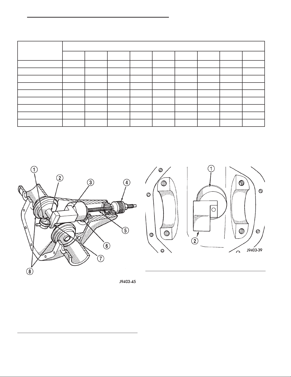
XJ TUBE, 181, AND 186 FBI AXLE 3 - 49
ADJUSTMENTS (Continued)
PINION GEAR DEPTH VARIANCE
Original Pinion
Replacement Pinion Gear Depth Variance
Gear Depth
Variance
−4 −3 −2 −1 0 +1 +2 +3 +4
+4 +0.008 +0.007 +0.006 +0.005 +0.004 +0.003 +0.002 +0.001 0
+3 +0.007 +0.006 +0.005 +0.004 +0.003 +0.002 +0.001 0 −0.001
+2 +0.006 +0.005 +0.004 +0.003 +0.002 +0.001 0 −0.001 −0.002
+1 +0.005 +0.004 +0.003 +0.002 +0.001 0 −0.001 −0.002 −0.003
0 +0.004 +0.003 +0.002 +0.001 0 −0.001 −0.002 −0.003 −0.004
−1 +0.003 +0.002 +0.001 0 −0.001 −0.002 −0.003 −0.004 −0.005
−2 +0.002 +0.001 0 −0.001 −0.002 −0.003 −0.004 −0.005 −0.006
−3 +0.001 0 −0.001 −0.002 −0.003 −0.004 −0.005 −0.006 −0.007
−4 0 −0.001 −0.002 −0.003 −0.004 −0.005 −0.006 −0.007 −0.008
PINION DEPTH MEASUREMENT AND ADJUSTMENT
Measurements are taken with pinion bearing cups
and pinion bearings installed in the axle housing.
Take measurements with Pinion Gauge Set and Dial
Indicator C-3339 (Fig. 73).
(2) Insert assembled height gauge components,
rear bearing and screw into axle housing through
pinion bearing cups (Fig. 74).
(3) Install front pinion bearing and Cone-nut 6740
hand tight (Fig. 73).
Fig. 73 Pinion Gear Depth Gauge Tools—Typical
1 – DIAL INDICATOR
2 – ARBOR
3 – PINION HEIGHT BLOCK
4 – CONE
5 – SCREW
6 – PINION BLOCK
7 – SCOOTER BLOCK
8 – ARBOR DISC
(1) Assemble Pinion Height Block 6739, Pinion
Block 6733, and rear pinion bearing onto Screw 6741
(Fig. 73).
Fig. 74 Pinion Height Block—Typical
1 – PINION BLOCK
2 – PINION HEIGHT BLOCK
(4) Place Arbor Disc 6732 on Arbor D-115-3 in position in axle housing side bearing cradles (Fig. 75).
Install differential bearing caps on Arbor Discs and
tighten cap bolts to 41 N·m (30 ft. lbs.).
NOTE: Arbor Discs 6732 has different step diameters to fit other axles. Choose proper step for axle
being serviced.
(5) Assemble Dial Indicator C-3339 into Scooter
Block D-115-2 and secure set screw.
(6) Place Scooter Block/Dial Indicator in position
in axle housing so dial probe and scooter block are
flush against the rearward surface of the pinion
Page 50
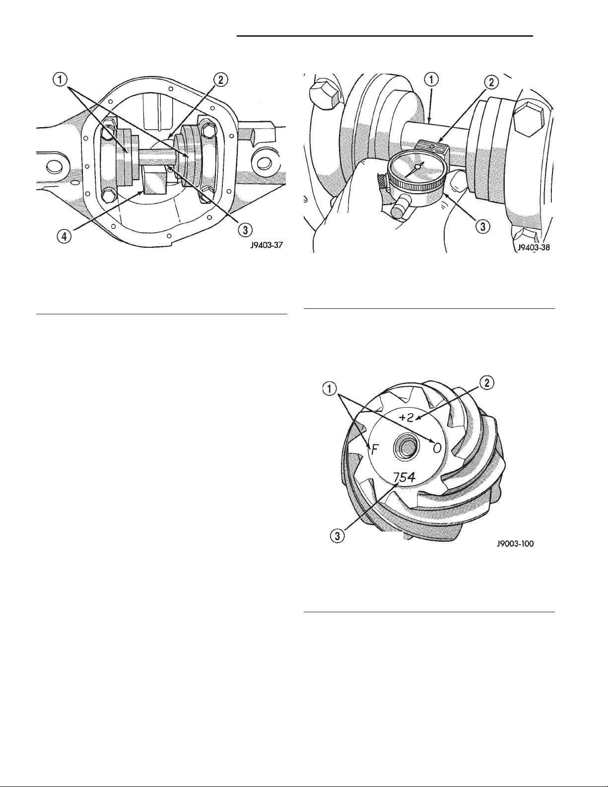
3 - 50 TUBE, 181, AND 186 FBI AXLE XJ
ADJUSTMENTS (Continued)
Fig. 75 Gauge Tools In Housing—Typical
1 – ARBOR DISC
2 – PINION BLOCK
3 – ARBOR
4 – PINION HEIGHT BLOCK
height block (Fig. 73). Hold scooter block in place and
zero the dial indicator face to the pointer. Tighten
dial indicator face lock screw.
(7) With scooter block still in position against the
pinion height block, slowly slide the dial indicator
probe over the edge of the pinion height block.
(8) Slide the dial indicator probe across the gap
between the pinion height block and the arbor bar
with the scooter block against the pinion height block
(Fig. 76). When the dial probe contacts the arbor bar,
the dial pointer will turn clockwise. Bring dial
pointer back to zero against the arbor bar, do not
turn dial face. Continue moving the dial probe to the
crest of the arbor bar and record the highest reading.
If the dial indicator can not achieve the zero reading,
the rear bearing cup or the pinion depth gauge set is
not installed correctly.
(9) Select a shim/oil baffle equal to the dial indicator reading plus the pinion depth variance number
etched in the face of the pinion (Fig. 71). For example, if the depth variance is –2, add +0.002 in. to the
dial indicator reading.
186 FBI PINION GEAR DEPTH
Fig. 76 Pinion Gear Depth Measurement—Typical
1 – ARBOR
2 – SCOOTER BLOCK
3 – DIAL INDICATOR
pinion is 92.08 mm (3.625 in.). The standard depth
provides the best gear tooth contact pattern. Refer to
Backlash and Contact Pattern Analysis paragraph in
this section for additional information.
Fig. 77 Pinion Gear ID Numbers
1 – PRODUCTION NUMBERS
2 – DRIVE PINION GEAR DEPTH VARIANCE
3 – GEAR MATCHING NUMBER (SAME AS RING GEAR
NUMBER)
GENERAL INFORMATION
Ring gear and pinion are supplied as matched sets
only. The identifying numbers for the ring gear and
pinion are etched into the face of each gear (Fig. 77).
A plus (+) number, minus (–) number or zero (0) is
etched into the face of the pinion gear head. This
number is the amount (in thousandths of an inch)
the depth varies from the standard depth setting of a
pinion etched with a (0). The standard setting from
the center line of the ring gear to the back face of the
Compensation for pinion depth variance is
achieved with a select shim/oil slinger. The shim/oil
slinger is placed between the rear pinion bearing and
the pinion gear head (Fig. 78).
If a new gear set is being installed, note the depth
variance etched into both the original and replacement pinion. Add or subtract the thickness of the
original depth shims to compensate for the difference
in the depth variances. Refer to the Depth Variance
chart.
Page 51
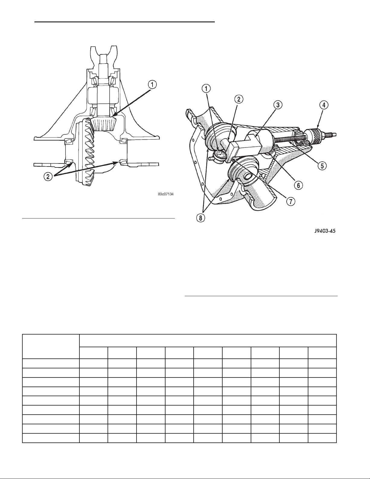
XJ TUBE, 181, AND 186 FBI AXLE 3 - 51
ADJUSTMENTS (Continued)
PINION DEPTH MEASUREMENT AND ADJUSTMENT
Measurements are taken with pinion bearing cups
and pinion bearings installed in the axle housing.
Take measurements with Pinion Gauge Set 6774 and
Dial Indicator C-3339 (Fig. 79).
Fig. 78 Shim Locations
1 – PINION GEAR DEPTH SHIM/OIL BAFFLE
2 – DIFFERENTIAL BEARING SHIM
Note where Old and New Pinion Marking columns
intersect. Intersecting figure represents plus or
minus the amount needed.
Note the etched number on the face of the drive
pinion (–1, –2, 0, +1, +2, etc.). The numbers represent thousands of an inch deviation from the standard. If the number is negative, add that value to the
required thickness of the depth shim/oil slinger. If
the number is positive, subtract that value from the
thickness of the depth shim/oil slinger. If the number
is 0 no change is necessary.
PINION GEAR DEPTH VARIANCE
Original Pinion
Replacement Pinion Gear Depth Variance
Gear Depth
Variance
−4 −3 −2 −1 0 +1 +2 +3 +4
+4 +0.008 +0.007 +0.006 +0.005 +0.004 +0.003 +0.002 +0.001 0
+3 +0.007 +0.006 +0.005 +0.004 +0.003 +0.002 +0.001 0 −0.001
+2 +0.006 +0.005 +0.004 +0.003 +0.002 +0.001 0 −0.001 −0.002
+1 +0.005 +0.004 +0.003 +0.002 +0.001 0 −0.001 −0.002 −0.003
0 +0.004 +0.003 +0.002 +0.001 0 −0.001 −0.002 −0.003 −0.004
−1 +0.003 +0.002 +0.001 0 −0.001 −0.002 −0.003 −0.004 −0.005
−2 +0.002 +0.001 0 −0.001 −0.002 −0.003 −0.004 −0.005 −0.006
−3 +0.001 0 −0.001 −0.002 −0.003 −0.004 −0.005 −0.006 −0.007
−4 0 −0.001 −0.002 −0.003 −0.004 −0.005 −0.006 −0.007 −0.008
Fig. 79 Pinion Gear Depth Gauge Tools—Typical
1 – DIAL INDICATOR
2 – ARBOR
3 – PINION HEIGHT BLOCK
4 – CONE
5 – SCREW
6 – PINION BLOCK
7 – SCOOTER BLOCK
8 – ARBOR DISC
Page 52
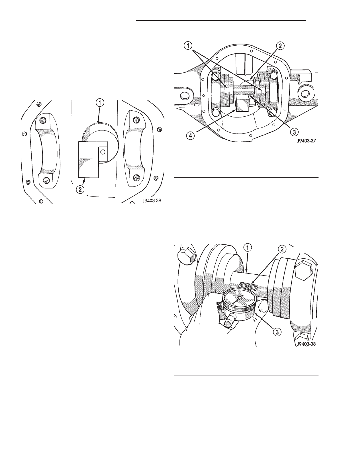
3 - 52 TUBE, 181, AND 186 FBI AXLE XJ
ADJUSTMENTS (Continued)
(1) Assemble Pinion Height Block 6739, Pinion
Block 6733, and rear pinion bearing onto Screw 6741
(Fig. 79).
(2) Insert assembled height gauge components,
rear bearing and screw into axle housing through
pinion bearing cups (Fig. 80).
(3) Install front pinion bearing and Cone-nut 6740
hand tight (Fig. 79).
Fig. 81 Gauge Tools In Housing—Typical
1 – ARBOR DISC
2 – PINION BLOCK
3 – ARBOR
4 – PINION HEIGHT BLOCK
Fig. 80 Pinion Height Block—Typical
1 – PINION BLOCK
2 – PINION HEIGHT BLOCK
(4) Place Arbor Disc 6732 on Arbor D-115-3 in position in axle housing side bearing cradles (Fig. 81).
Install differential bearing caps on Arbor Discs and
tighten cap bolts to 41 N·m (30 ft. lbs.).
NOTE: Arbor Discs 6732 has different step diameters to fit other axles. Choose proper step for axle
being serviced.
(5) Assemble Dial Indicator C-3339 into Scooter
Block D-115-2 and secure set screw.
(6) Place Scooter Block/Dial Indicator in position
in axle housing so dial probe and scooter block are
flush against the rearward surface of the pinion
height block (Fig. 79). Hold scooter block in place and
zero the dial indicator face to the pointer. Tighten
dial indicator face lock screw.
(7) With scooter block still in position against the
pinion height block, slowly slide the dial indicator
probe over the edge of the pinion height block.
(8) Slide the dial indicator probe across the gap
between the pinion height block and the arbor bar
with the scooter block against the pinion height block
(Fig. 82). When the dial probe contacts the arbor bar,
the dial pointer will turn clockwise. Bring dial
pointer back to zero against the arbor bar, do not
turn dial face. Continue moving the dial probe to the
crest of the arbor bar and record the highest reading.
If the dial indicator can not achieve the zero reading,
the rear bearing cup or the pinion depth gauge set is
not installed correctly.
(9) Select a shim/oil slinger equal to the dial indicator reading plus the drive pinion depth variance
number etched in the face of the pinion (Fig. 77). For
example, if the depth variance is –2, add +0.002 in.
to the dial indicator reading.
Fig. 82 Pinion Gear Depth Measurement—Typical
1 – ARBOR
2 – SCOOTER BLOCK
3 – DIAL INDICATOR
181 FBI DIFFERENTIAL BEARING PRELOAD AND GEAR BACKLASH
INTRODUCTION
Differential side bearing preload and gear backlash
is achieved by selective shims positioned behind the
Page 53
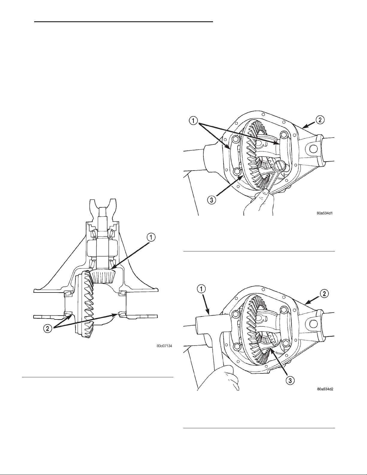
XJ TUBE, 181, AND 186 FBI AXLE 3 - 53
ADJUSTMENTS (Continued)
differential side bearing cones. The proper shim
thickness can be determined using slip-fit dummy
bearings D-348 in place of the differential side bearings and a dial indicator C-3339. Before proceeding
with the differential bearing preload and gear backlash measurements, measure the pinion gear depth
and prepare the pinion for installation. Establishing
proper pinion gear depth is essential to establishing
gear backlash and tooth contact patterns. After the
overall shim thickness to take up differential side
play is measured, the pinion is installed, and the
gear backlash shim thickness is measured. The overall shim thickness is the total of the dial indicator
reading and the preload specification added together.
The gear backlash measurement determines the
thickness of the shim used on the ring gear side of
the differential case. Subtract the gear backlash shim
thickness from the total overall shim thickness and
select that amount for the pinion gear side of the differential (Fig. 83). Differential shim measurements
are performed with axle spreader W-129-B removed.
(2) Remove factory installed shims from differential case.
(3) Install ring gear on differential case and
tighten bolts to specification.
(4) Install dummy side bearings D-348 on differential case.
(5) Install differential case in axle housing.
(6) Install the marked bearing caps in their correct
positions. Install and snug the bolts (Fig. 84).
Fig. 83 Axle Adjustment Shim Locations
1 – PINION GEAR DEPTH SHIM/OIL BAFFLE
2 – DIFFERENTIAL BEARING SHIM
SHIM SELECTION
NOTE: It is difficult to salvage the differential side
bearings during the removal procedure. Install
replacement bearings if necessary.
(1) Remove differential side bearings from differ-
ential case.
Fig. 84 Tighten Bolts Holding Bearing Caps
1 – BEARING CAP
2 – AXLE HOUSING
3 – DIFFERENTIAL CASE
(7) Using a dead-blow type mallet, seat the differential dummy bearings to each side of the axle housing (Fig. 85) and (Fig. 86).
Fig. 85 Seat Pinion Gear Side Differential Dummy
Side Bearing
1 – MALLET
2 – AXLE HOUSING
3 – DIFFERENTIAL CASE
(8) Thread guide stud C-3288-B into rear cover
bolt hole below ring gear (Fig. 87).
Page 54
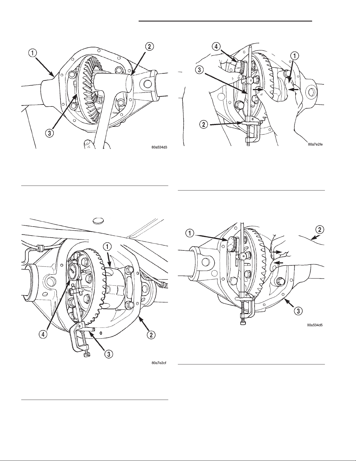
3 - 54 TUBE, 181, AND 186 FBI AXLE XJ
ADJUSTMENTS (Continued)
Fig. 86 Seat Ring Gear Side Differential Dummy
Side Bearing
1 – AXLE HOUSING
2 – MALLET
3 – DIFFERENTIAL CASE
(9) Attach a dial indicator C-3339 to guide stud.
Position the dial indicator plunger on a flat surface
between the ring gear bolt heads (Fig. 87).
Fig. 88 Hold Differential Case and Zero Dial
Indicator
1 – FORCE DIFFERENTIAL CASE TO PINION GEAR SIDE
2 – SPECIAL TOOL C-3288–B
3 – SPECIAL TOOL C-3339
4 – ZERO DIAL INDICATOR FACE
(12) Push and hold differential case to ring gear
side of the axle housing (Fig. 89).
(13) Record dial indicator reading (Fig. 89).
Fig. 87 Differential Side play Measurement
1 – DIFFERENTIAL CASE
2 – AXLE HOUSING
3 – SPECIAL TOOL C-3288–B
4 – SPECIAL TOOL C-3339
(10) Push and hold differential case to pinion gear
side of axle housing (Fig. 88).
(11) Zero dial indicator face to pointer (Fig. 88).
Fig. 89 Hold Differential Case and Read Dial
Indicator
1 – READ DIAL INDICATOR
2 – FORCE DIFFERENTIAL CASE TO RING GEAR SIDE
3 – AXLE HOUSING
(14) Add 0.008 in. (0.2 mm) to the zero end play
total. This new total represents the thickness of
shims to compress, or preload the new bearings when
the differential is installed.
(15) Rotate dial indicator out of the way on the
guide stud.
(16) Remove differential case and dummy bearings
from axle housing.
Page 55
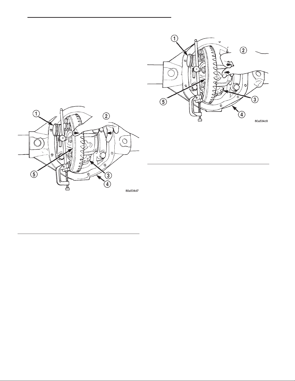
XJ TUBE, 181, AND 186 FBI AXLE 3 - 55
ADJUSTMENTS (Continued)
(17) Install the pinion gear in axle housing. Install
the pinion yoke and establish the correct pinion
rotating torque.
(18) Install differential case and dummy bearings
D-348 in axle housing (without shims), install bearing caps and tighten bolts snug.
(19) Seat ring gear side dummy bearing (Fig. 86).
(20) Position the dial indicator plunger on a flat
surface between the ring gear bolt heads. (Fig. 87).
(21) Push and hold differential case toward pinion
gear (Fig. 90).
(22) Zero dial indicator face to pointer (Fig. 90).
Fig. 91 Hold Differential Case and Read Dial
Indicator
1 – READ DIAL INDICATOR
2 – FORCE DIFFERENTIAL CASE TO RING GEAR SIDE
3 – PINION GEAR
4 – AXLE HOUSING
5 – DIFFERENTIAL CASE
Fig. 90 Hold Differential Case and Zero Dial
Indicator
1 – ZERO DIAL INDICATOR FACE
2 – FORCE DIFFERENTIAL CASE TO PINION GEAR SIDE
3 – PINION GEAR
4 – AXLE HOUSING
5 – DIFFERENTIAL CASE
(23) Push and hold differential case to ring gear
side of the axle housing (Fig. 91).
(24) Record dial indicator reading (Fig. 91).
(25) Subtract 0.002 in. (0.05 mm) from the dial
indicator reading to compensate for backlash between
ring and pinion gears. This total is the thickness
shim required to achieve proper backlash.
(26) Subtract the backlash shim thickness from
the total preload shim thickness. The remainder is
the shim thickness required on the pinion side of the
axle housing.
(27) Rotate dial indicator out of the way on guide
stud.
(28) Remove differential case and dummy bearings
from axle housing.
(29) Install the selected side bearing shims onto
the differential case hubs.
(30) Install side bearings and cups on differential
case.
(31) Install spreader W-129-B, utilizing some items
from Adapter Set 6987, on axle housing and spread
axle opening enough to receive differential case.
(32) Install differential case into the axle housing.
(33) Remove spreader from axle housing.
(34) Rotate the differential case several times to
seat the side bearings.
(35) Position the indicator plunger against a ring
gear tooth (Fig. 92).
(36) Push and hold ring gear upward while not
allowing the pinion gear to rotate.
(37) Zero dial indicator face to pointer.
(38) Push and hold ring gear downward while not
allowing the pinion gear to rotate. Dial indicator
reading should be between 0.12 mm (0.005 in.) and
0.20 mm (0.008 in.). If backlash is not within specifications transfer the necessary amount of shim thickness from one side of the axle housing to the other
(Fig. 93).
(39) Verify differential case and ring gear runout
by measuring ring to pinion gear backlash at eight
locations around the ring gear. Readings should not
vary more than 0.05 mm (0.002 in.). If readings vary
more than specified, the ring gear or the differential
case is defective.
After the proper backlash is achieved, perform
Gear Contact Pattern Analysis procedure.
Page 56
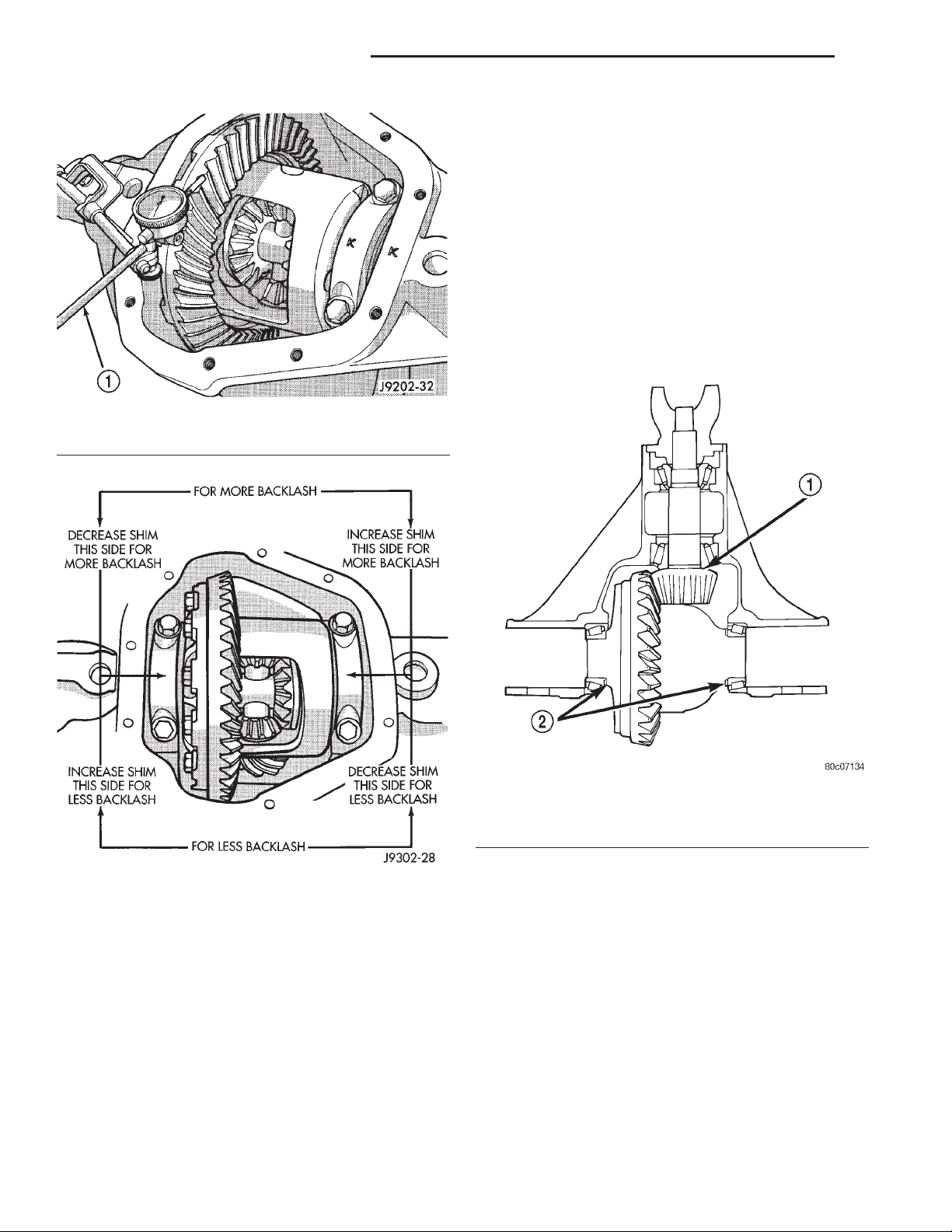
3 - 56 TUBE, 181, AND 186 FBI AXLE XJ
ADJUSTMENTS (Continued)
proper pinion gear depth is essential to establishing
gear backlash and tooth contact patterns. After the
overall shim thickness to take up differential side
play is measured, the pinion is installed, and the
gear backlash shim thickness is measured. The overall shim thickness is the total of the dial indicator
reading and the preload specification added together.
The gear backlash measurement determines the
thickness of the shim used on the ring gear side of
the differential case. Subtract the gear backlash shim
thickness from the total overall shim thickness and
select that amount for the pinion gear side of the differential (Fig. 94). Differential shim measurements
are performed with axle spreader W-129-B removed.
Fig. 92 Ring Gear Backlash Measurement
1 – DIAL INDICATOR
Fig. 93 Backlash Shim Adjustment
186 FBI DIFFERENTIAL BEARING PRELOAD AND GEAR BACKLASH
INTRODUCTION
Differential side bearing preload and gear backlash
is achieved by selective shims positioned behind the
differential side bearing cones. The proper shim
thickness can be determined using slip-fit dummy
bearings D-348 in place of the differential side bearings and a dial indicator C-3339. Before proceeding
with the differential bearing preload and gear backlash measurements, measure the pinion gear depth
and prepare the pinion for installation. Establishing
Fig. 94 Axle Adjustment Shim Locations
1 – PINION GEAR DEPTH SHIM/OIL BAFFLE
2 – DIFFERENTIAL BEARING SHIM
SHIM SELECTION
NOTE: It is difficult to salvage the differential side
bearings during the removal procedure. Install
replacement bearings if necessary.
(1) Remove differential side bearings from differ-
ential case.
(2) Remove factory installed shims from differen-
tial case.
(3) Install ring gear on differential case and
tighten bolts to specification.
(4) Install dummy side bearings D-348 on differen-
tial case.
(5) Install differential case in axle housing.
Page 57
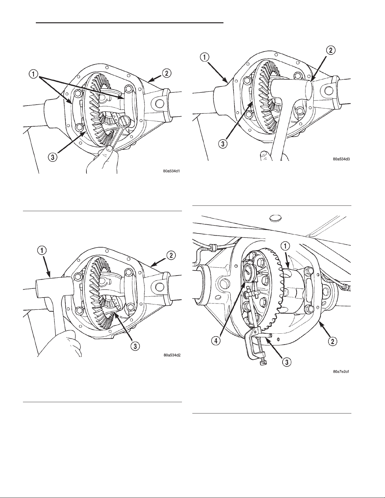
XJ TUBE, 181, AND 186 FBI AXLE 3 - 57
ADJUSTMENTS (Continued)
(6) Install the marked bearing caps in their correct
positions. Install and snug the bolts (Fig. 95).
Fig. 97 Seat Ring Gear Side Differential Dummy
Fig. 95 Tighten Bolts Holding Bearing Caps
1 – BEARING CAP
2 – AXLE HOUSING
3 – DIFFERENTIAL CASE
1 – AXLE HOUSING
2 – MALLET
3 – DIFFERENTIAL CASE
Side Bearing
(7) Using a dead-blow type mallet, seat the differential dummy bearings to each side of the axle housing (Fig. 96) and (Fig. 97).
Fig. 96 Seat Pinion Gear Side Differential Dummy
Side Bearing
1 – MALLET
2 – AXLE HOUSING
3 – DIFFERENTIAL CASE
(8) Thread guide stud C-3288-B into rear cover
bolt hole below ring gear (Fig. 98).
(9) Attach a dial indicator C-3339 to guide stud.
Position the dial indicator plunger on a flat surface
between the ring gear bolt heads (Fig. 98).
(10) Push and hold differential case to pinion gear
side of axle housing (Fig. 99).
(11) Zero dial indicator face to pointer (Fig. 99).
Fig. 98 Differential Side play Measurement
1 – DIFFERENTIAL CASE
2 – AXLE HOUSING
3 – SPECIAL TOOL C-3288–B
4 – SPECIAL TOOL C-3339
(12) Push and hold differential case to ring gear
side of the axle housing (Fig. 100).
(13) Record dial indicator reading (Fig. 100).
(14) Add 0.008 in. (0.2 mm) to the zero end play
total. This new total represents the thickness of
Page 58
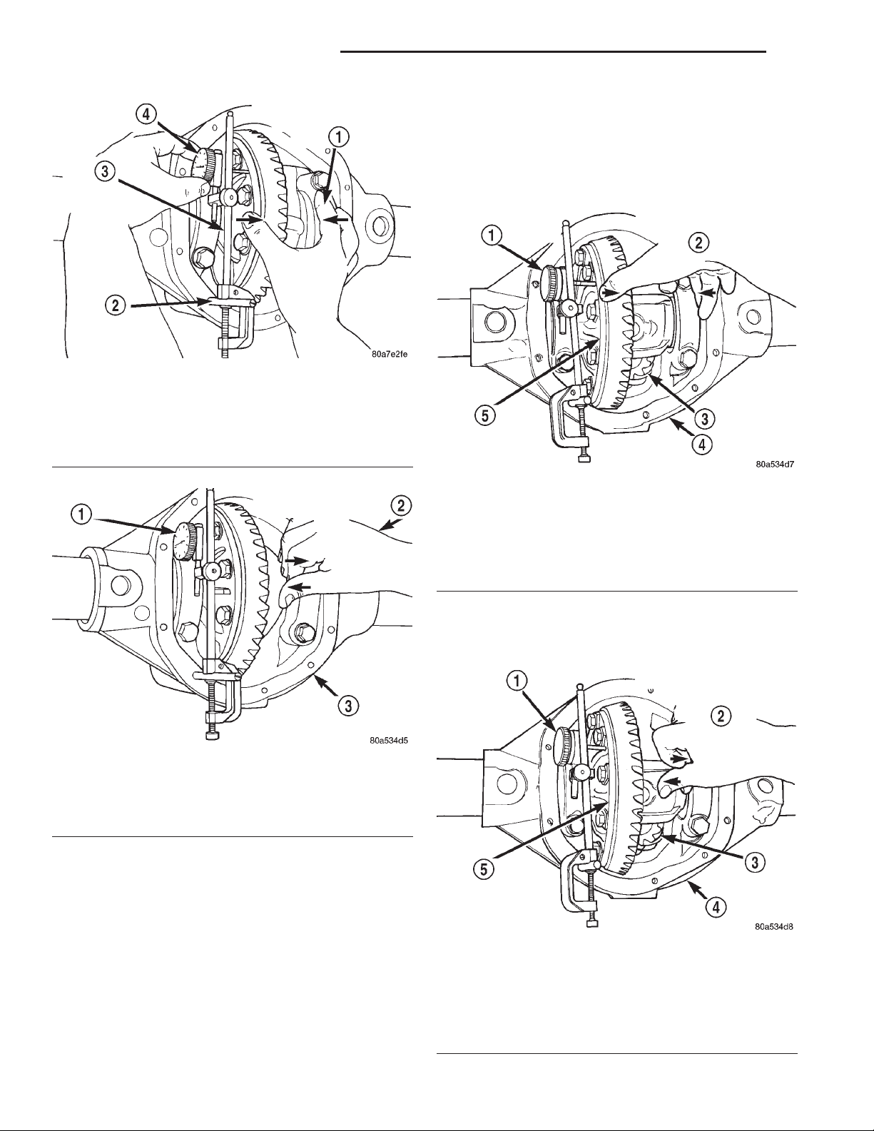
3 - 58 TUBE, 181, AND 186 FBI AXLE XJ
ADJUSTMENTS (Continued)
(19) Seat ring gear side dummy bearing (Fig. 97).
(20) Position the dial indicator plunger on a flat
surface between the ring gear bolt heads. (Fig. 98).
(21) Push and hold differential case toward pinion
gear (Fig. 101).
(22) Zero dial indicator face to pointer (Fig. 101).
Fig. 99 Hold Differential Case and Zero Dial
Indicator
1 – FORCE DIFFERENTIAL CASE TO PINION GEAR SIDE
2 – SPECIAL TOOL C-3288–B
3 – SPECIAL TOOL C-3339
4 – ZERO DIAL INDICATOR FACE
Fig. 100 Hold Differential Case and Read Dial
Indicator
1 – READ DIAL INDICATOR
2 – FORCE DIFFERENTIAL CASE TO RING GEAR SIDE
3 – AXLE HOUSING
shims to compress, or preload the new bearings when
the differential is installed.
(15) Rotate dial indicator out of the way on the
guide stud.
(16) Remove differential case and dummy bearings
from axle housing.
(17) Install the pinion in the axle housing. Install
the pinion yoke and establish the correct pinion
rotating torque.
(18) Install differential case and dummy bearings
D-348 in axle housing (without shims), install bearing caps and tighten bolts snug.
Fig. 101 Hold Differential Case and Zero Dial
Indicator
1 – ZERO DIAL INDICATOR FACE
2 – FORCE DIFFERENTIAL CASE TO PINION GEAR SIDE
3 – PINION GEAR
4 – AXLE HOUSING
5 – DIFFERENTIAL CASE
(23) Push and hold differential case to ring gear
side of the axle housing (Fig. 102).
(24) Record dial indicator reading (Fig. 102).
Fig. 102 Hold Differential Case and Read Dial
Indicator
1 – READ DIAL INDICATOR
2 – FORCE DIFFERENTIAL CASE TO RING GEAR SIDE
3 – PINION GEAR
4 – AXLE HOUSING
5 – DIFFERENTIAL CASE
Page 59
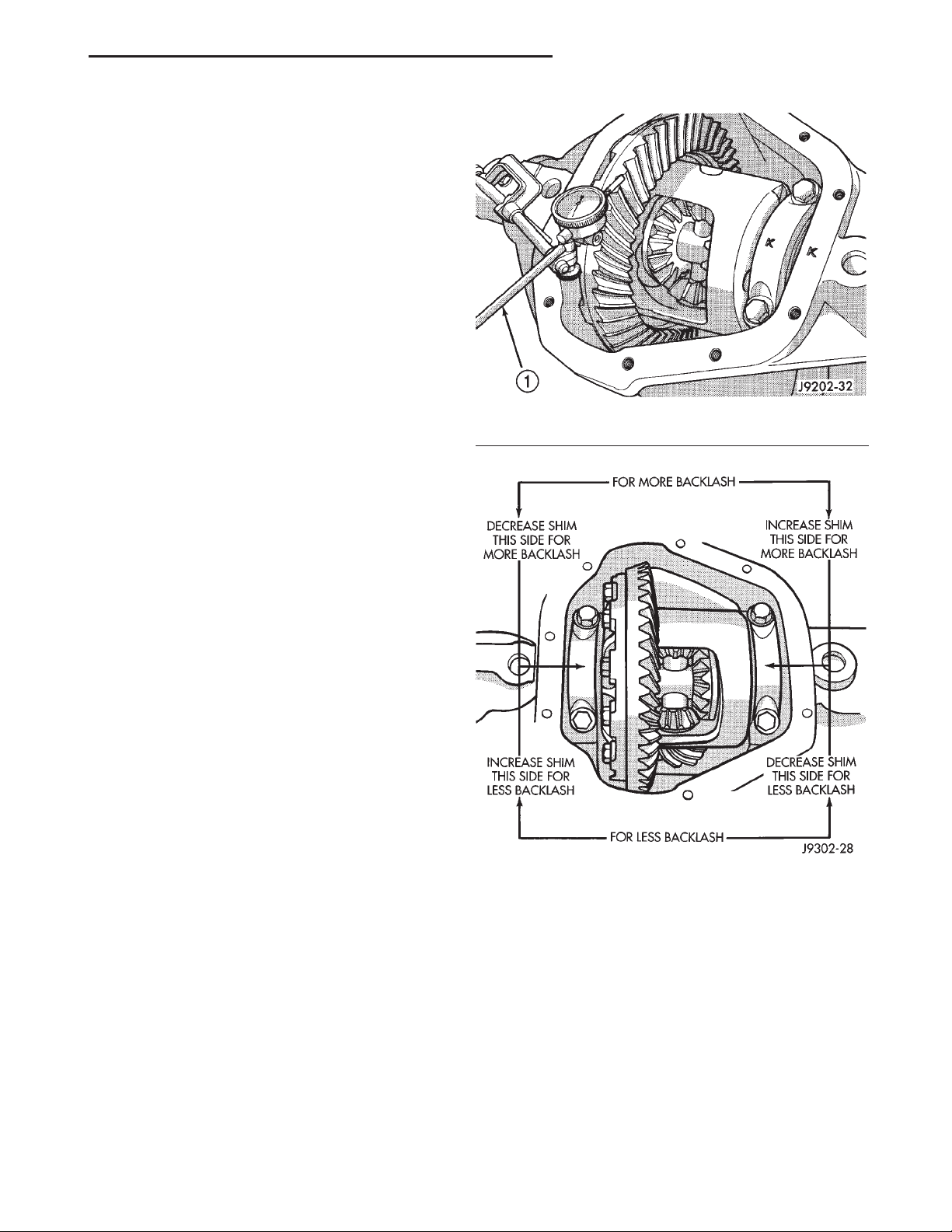
XJ TUBE, 181, AND 186 FBI AXLE 3 - 59
ADJUSTMENTS (Continued)
(25) Subtract 0.002 in. (0.05 mm) from the dial
indicator reading to compensate for backlash between
ring and pinion gears. This total is the thickness
shim required to achieve proper backlash.
(26) Subtract the backlash shim thickness from
the total preload shim thickness. The remainder is
the shim thickness required on the pinion side of the
axle housing.
(27) Rotate dial indicator out of the way on guide
stud.
(28) Remove differential case and dummy bearings
from axle housing.
(29) Install side bearing shims on differential case
hubs.
(30) Install side bearings and cups on differential
case.
(31) Install spreader W-129-B, utilizing some items
from Adapter Set 6987, on axle housing and spread
axle opening enough to receive differential case.
(32) Install differential case in axle housing.
(33) Remove spreader from axle housing.
(34) Rotate the differential case several times to
seat the side bearings.
(35) Position the indicator plunger against a ring
gear tooth (Fig. 103).
(36) Push and hold ring gear upward while not
allowing the pinion gear to rotate.
(37) Zero dial indicator face to pointer.
(38) Push and hold ring gear downward while not
allowing the pinion gear to rotate. Dial indicator
reading should be between 0.12 mm (0.005 in.) and
0.20 mm (0.008 in.). If backlash is not within specifications transfer the necessary amount of shim thickness from one side of the axle housing to the other
(Fig. 104).
(39) Verify differential case and ring gear runout
by measuring ring to pinion gear backlash at eight
locations around the ring gear. Readings should not
vary more than 0.05 mm (0.002 in.). If readings vary
more than specified, the ring gear or the differential
case is defective.
After the proper backlash is achieved, perform
Gear Contact Pattern Analysis procedure.
GEAR CONTACT PATTERN ANALYSIS
The ring gear and pinion teeth contact patterns
will show if the pinion depth is correct in the axle
housing. It will also show if the ring gear backlash
has been adjusted correctly. The backlash can be
adjusted within specifications to achieve desired
tooth contact patterns.
(1) Apply a thin coat of hydrated ferric oxide, or
equivalent, to the drive and coast side of the ring
gear teeth.
(2) Wrap, twist, and hold a shop towel around the
pinion yoke to increase the turning resistance of the
Fig. 103 Ring Gear Backlash Measurement
1 – DIAL INDICATOR
Fig. 104 Backlash Shim Adjustment
pinion. This will provide a more distinct contact pattern.
(3) Using a boxed end wrench on a ring gear bolt,
Rotate the differential case one complete revolution
in both directions while a load is being applied from
shop towel.
The areas on the ring gear teeth with the greatest
degree of contact against the pinion teeth will squeegee the compound to the areas with the least amount
of contact. Note and compare patterns on the ring
gear teeth to Gear Tooth Contact Patterns chart (Fig.
105) and adjust pinion depth and gear backlash as
necessary.
Page 60
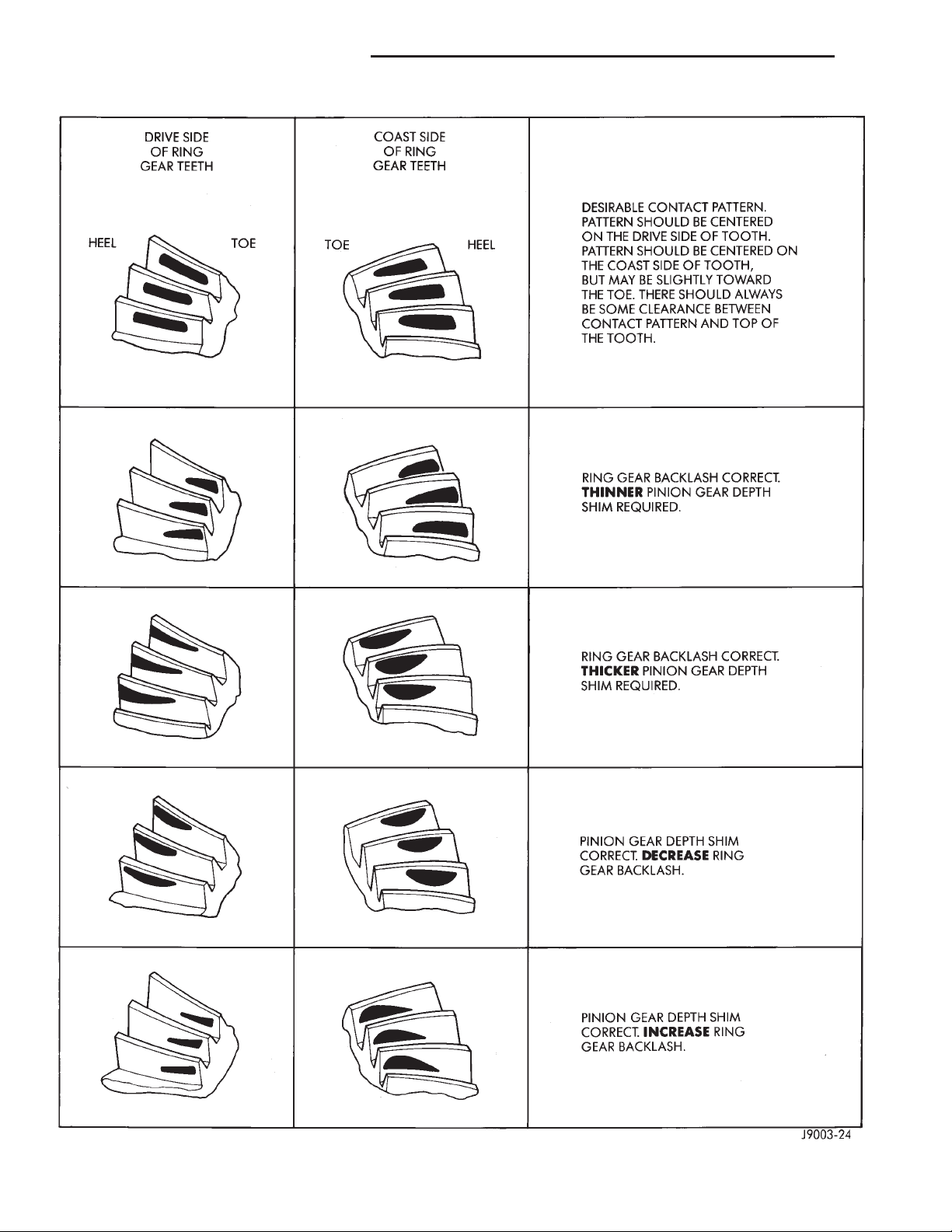
3 - 60 TUBE, 181, AND 186 FBI AXLE XJ
ADJUSTMENTS (Continued)
Fig. 105 Gear Tooth Contact Patterns
Page 61
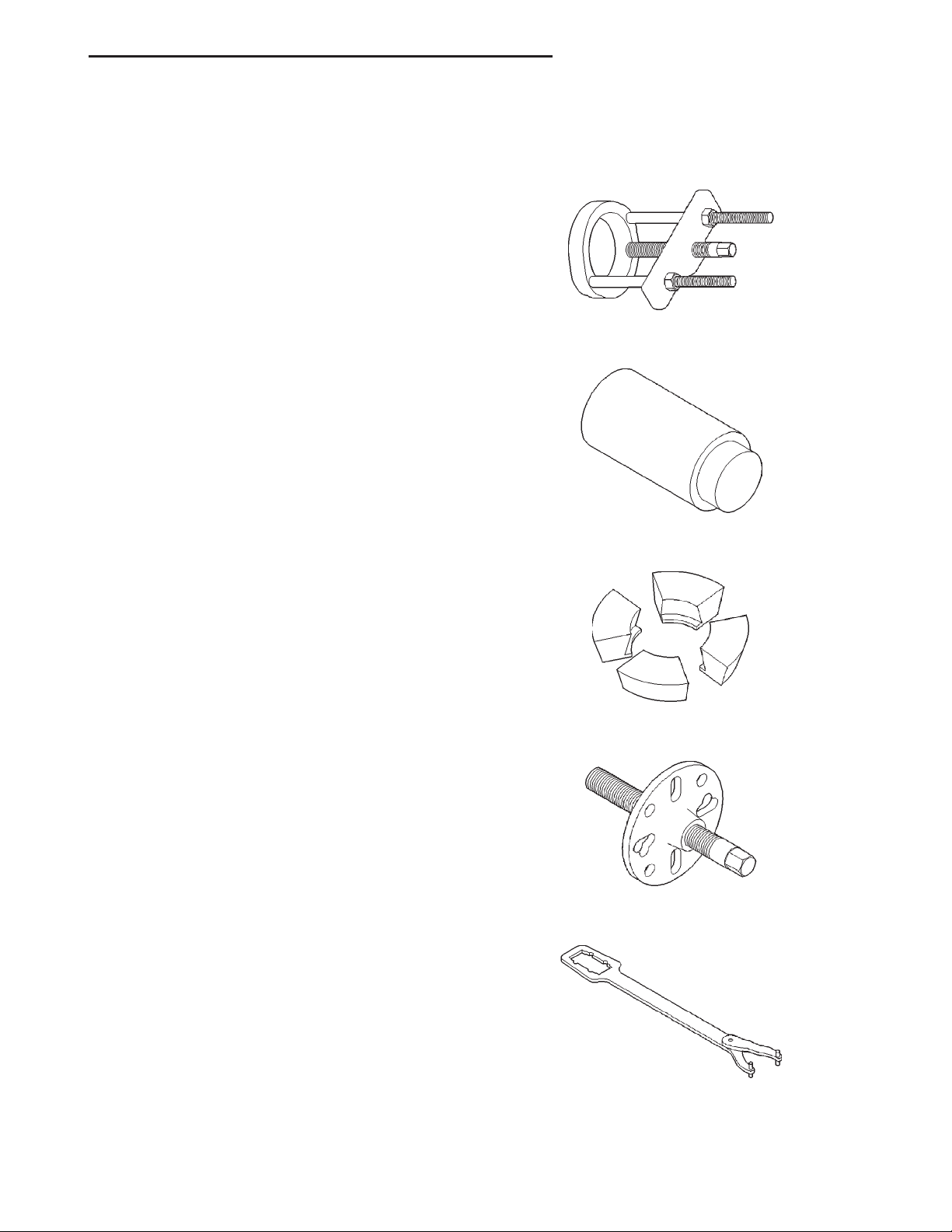
XJ TUBE, 181, AND 186 FBI AXLE 3 - 61
SPECIFICATIONS
181 FBI AXLE
Axle Type .......................... Hypoid
Lubricant–Std. .... SAEThermally Stable 80W–90
Lubricant–Heavy Duty . . . SAE 75W–140 Synthetic
Lube Capacity ............... 1.48 L (3.13 pts.)
Axle Ratio ................ 3.07, 3.55, 3.73, 4.10
Differential Side Gear Clearance . . . 0.12–0.20 mm
(0.005–0.008 in.)
Ring Gear Diameter ......... 18.09 cm (7.125 in.)
Backlash ........... 0–0.15 mm (0.005–0.008 in.)
Pinion Std. Depth ........... 92.1 mm (3.625 in.)
Pinion Bearing Rotating Torque ...............
Original Bearings ....... 1–2N·m(10–20 in. lbs.)
New Bearings ......... 1.5–4 N·m (15–35 in. lbs.)
186 FBI AXLE
Axle Type .......................... Hypoid
Lubricant–Std. .... SAEThermally Stable 80W–90
Lubricant–Heavy Duty . . . SAE 75W–140 Synthetic
Lube Capacity ................ 1.18 L (2.5 pts.)
Axle Ratio ................ 3.07, 3.55, 3.73, 4.10
Differential Side Gear Clearance . . . 0.12–0.20 mm
(0.005–0.008 in.)
Ring Gear Diameter ......... 18.59 cm (7.33 in.)
Backlash ........... 0–0.15 mm (0.005–0.008 in.)
Pinion Std. Depth ........... 92.1 mm (3.625 in.)
Pinion Bearing Rotating Torque ...............
Original Bearings ....... 1–2N·m(10–20 in. lbs.)
New Bearings ......... 1.5–4 N·m (15–35 in. lbs.)
SPECIAL TOOLS
181 and 186 FBI AXLE
Puller—C-293-PA
Plug—SP-3289
Adapter—C-293-39
TORQUE
DESCRIPTION TORQUE
Fill Hole Plug .............. 34N·m(25ft.lbs.)
Diff. Cover Bolt ............. 41N·m(30ft.lbs.)
Bearing Cap Bolt............ 61N·m(45ft.lbs.)
Ring Gear Bolt ....... 95–122 N·m (70–90 ft. lbs.)
Axle Nut ................ 237N·m(175 ft. lbs.)
Hub Brg. Bolt ............. 102N·m(75ft.lbs.)
Lower Ball Stud ........... 108N·m(80ft.lbs.)
Upper Ball Stud ........... 101N·m(75ft.lbs.)
Puller—C-452
Wrench—C-3281
Page 62
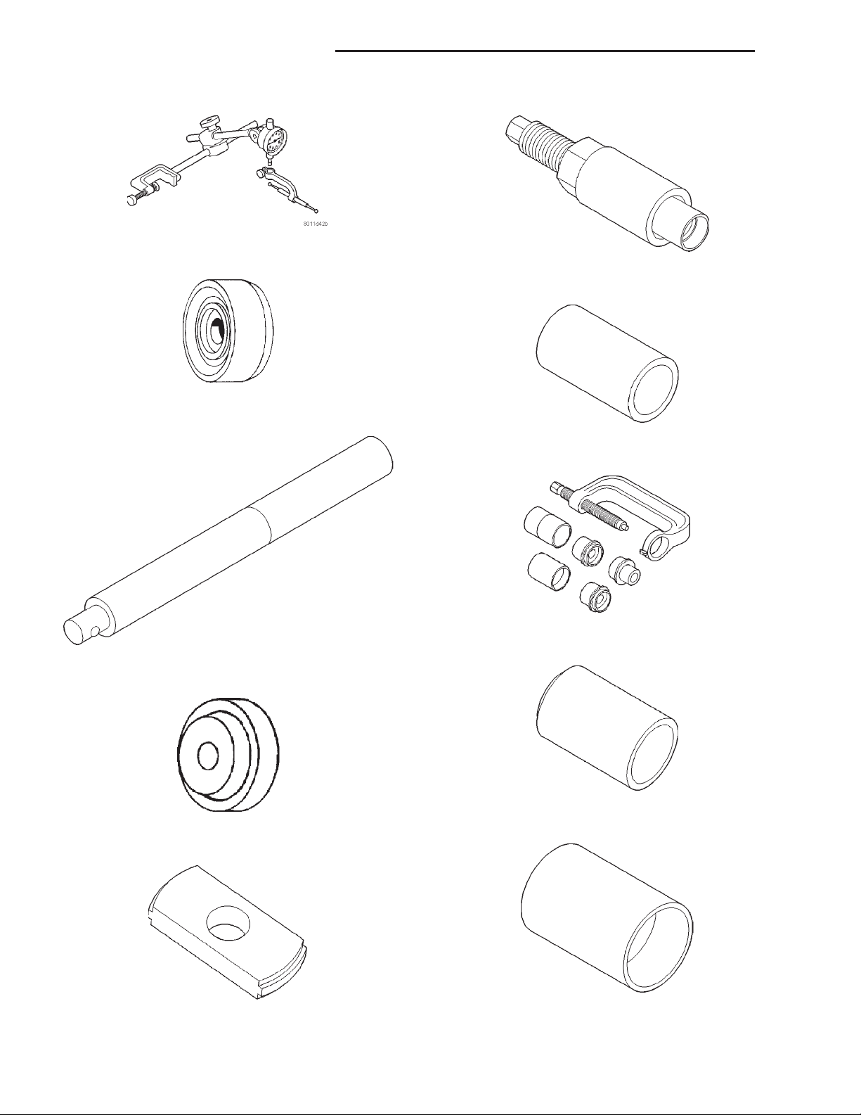
3 - 62 TUBE, 181, AND 186 FBI AXLE XJ
SPECIAL TOOLS (Continued)
Dial Indicator—C-3339
Installer—W-162-D
Driver—C-3716-A
Cup—8109
Handle—C-4171
Installer—D-146
Remover—D-149
Remover/Installer—6289
Installer—6761
Installer—6752
Page 63
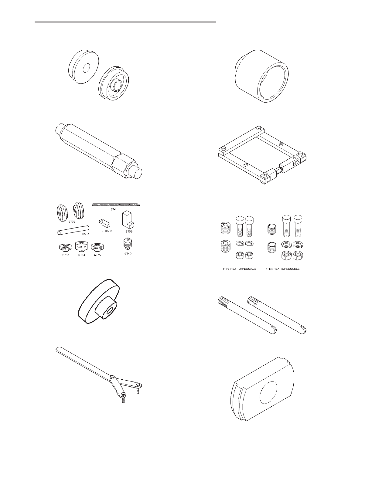
XJ TUBE, 181, AND 186 FBI AXLE 3 - 63
SPECIAL TOOLS (Continued)
Installer Discs—8110
Turnbuckle—6797
Tool Set, Pinion Depth—6774
Installer—C-3972-A
Spreader—W-129-B
Adapter Kit—6987
Gauge Block—6733
Spanner—6958
Pilot Stud—C-3288-B
Remover—D-147
Page 64
3 - 64 TUBE, 181, AND 186 FBI AXLE XJ
SPECIAL TOOLS (Continued)
Installer—D-144
Installer—W-262
Page 65
XJ 194 RBI AXLE 3 - 65
194 RBI AXLE
TABLE OF CONTENTS
page page
DESCRIPTION AND OPERATION
194 RBI AXLE ...........................65
LUBRICANT.............................66
STANDARD DIFFERENTIAL.................66
TRAC-LOKY DIFFERENTIAL ................66
DIAGNOSIS AND TESTING
GENERAL INFORMATION ..................67
GEAR NOISE............................70
BEARING NOISE .........................70
LOW SPEED KNOCK......................70
VIBRATION .............................70
DRIVELINE SNAP ........................70
TRAC–LOKY DIFFERENTIAL NOISE ..........70
TRAC–LOKY TEST .......................71
SERVICE PROCEDURES
LUBRICANT CHANGE .....................71
REMOVAL AND INSTALLATION
REAR AXLE .............................72
PINION SHAFT SEAL......................72
COLLAPSIBLE SPACER....................74
AXLE SHAFT ............................76
AXLE SHAFT SEAL AND BEARING ...........77
DESCRIPTION AND OPERATION
194 RBI AXLE
DESCRIPTION
The 194 Rear Beam-design Iron (RBI) axle housing
has an iron center casting (differential housing) with
axle shaft tubes extending from either side. The
tubes are pressed into and welded to the differential
housing to form a one-piece axle housing.
The integral type, hypoid gear design, housing has
the centerline of the pinion set below the centerline
of the ring gear.
The axle has a vent hose to relieve internal pressure caused by lubricant vaporization and internal
expansion.
The axles are equipped with semi–floating axle
shafts, meaning that loads are supported by the axle
shaft and bearings. The axle shafts are retained by
C–clips in the differential side gears.
The cover provides a means for servicing the differential without removing the axle.
For vehicles equipped with ABS brakes, the axles
have a tone ring pressed onto the axle shaft. Use care
when removing axle shafts to ensure that the tone
wheel or the wheel speed sensor are not damaged.
DIFFERENTIAL ..........................78
DIFFERENTIAL SIDE BEARINGS .............80
RING GEAR.............................80
PINION GEAR ...........................81
FINAL ASSEMBLY ........................85
DISASSEMBLY AND ASSEMBLY
STANDARD DIFFERENTIAL.................86
TRAC-LOKY DIFFERENTIAL ................87
CLEANING AND INSPECTION
AXLE COMPONENTS .....................91
TRAC-LOKY ............................91
ADJUSTMENTS
PINION GEAR DEPTH .....................91
DIFFERENTIAL BEARING PRELOAD AND
GEAR BACKLASH.......................94
GEAR CONTACT PATTERN ANALYSIS ........97
SPECIFICATIONS
194 RBI AXLE ...........................99
194 RBI AXLE ...........................99
SPECIAL TOOLS
194 RBI AXLE ...........................99
The 194 RBI axle has the assembly part number
and gear ratio listed on a tag. The tag is attached to
the differential housing by a cover bolt. Build date
identification codes are stamped on the cover side of
an axle shaft tube.
The differential case is a one-piece design. The differential pinion mate shaft is retained with a
threaded pin. Differential bearing preload and ring
gear backlash is adjusted by the use of selective
spacer shims. Pinion bearing preload is set and
maintained by the use of a collapsible spacer (Fig. 1).
Axles equipped with a Trac-Loky differential are
optional. A Trac-Lok differential has a one-piece differential case, and the same internal components as
a standard differential, plus two clutch disc packs.
OPERATION
The axle receives power from the transmission/
transfer case through the rear propeller shaft. The
rear propeller shaft is connected to the pinion gear
which rotates the differential through the gear mesh
with the ring gear bolted to the differential case. The
engine power is transmitted to the axle shafts
through the pinion mate and side gears. The side
gears are splined to the axle shafts.
Page 66
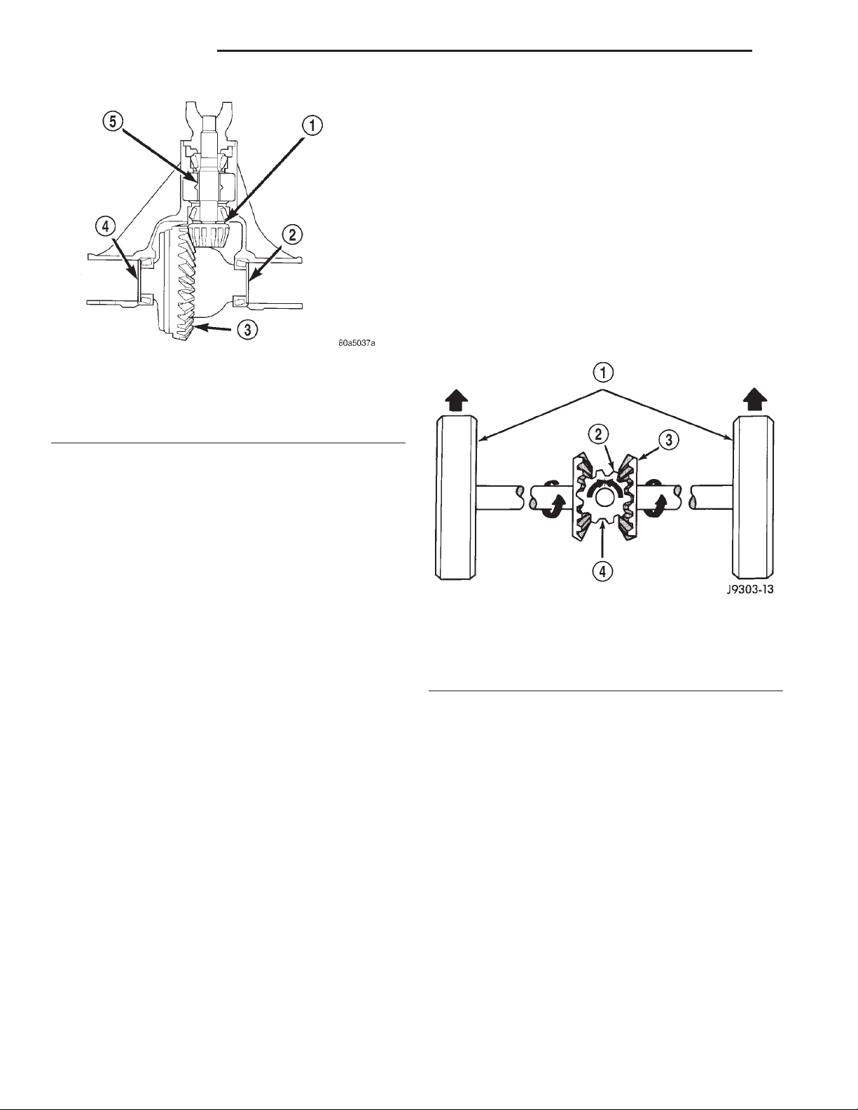
3 - 66 194 RBI AXLE XJ
DESCRIPTION AND OPERATION (Continued)
OPERATION
In operation, power flow occurs as follows:
• The pinion gear rotates the ring gear
• The ring gear (bolted to the differential case)
rotates the case
• The differential pinion gears (mounted on the
pinion mate shaft in the case) rotate the side gears
• The side gears (splined to the axle shafts) rotate
the shafts
During straight-ahead driving, the differential pinion gears do not rotate on the pinion mate shaft. This
occurs because input torque applied to the gears is
divided and distributed equally between the two side
gears. As a result, the pinion gears revolve with the
Fig. 1 Shim Locations
1 – PINION GEAR DEPTH SHIM
2 – DIFFERENTIAL BEARING SHIM-PINION GEAR SIDE
3 – RING GEAR
4 – DIFFERENTIAL BEARING SHIM-RING GEAR SIDE
5 – COLLAPSIBLE SPACER
pinion mate shaft but do not rotate around it (Fig. 2).
LUBRICANT
DESCRIPTION
A multi-purpose, hypoid gear lubricant which conforms to the following specifications should be used.
Mopart Hypoid Gear Lubricant conforms to all of
these specifications.
• The lubricant should have MIL–L–2105C and
API GL 5 quality specifications.
• Lubricant is a thermally stable SAE 80W–90
gear lubricant.
• Lubricant for axles intended for heavy-duty or
trailer tow use is SAE 75W–140 SYNTHETIC gear
lubricant.
Trac-lok differentials require the addition of 3.5 oz.
of friction modifier to the axle lubricant. The 194 RBI
axle lubricant capacity is 1.66L (3.50 pts.) total,
including the friction modifier if necessary.
CAUTION: If axle is submerged in water, lubricant
must be replaced immediately to avoid possible
premature axle failure.
STANDARD DIFFERENTIAL
DESCRIPTION
The differential gear system divides the torque
between the axle shafts. It allows the axle shafts to
rotate at different speeds when turning corners.
Each differential side gear is splined to an axle
shaft. The pinion gears are mounted on a pinion
mate shaft and are free to rotate on the shaft. The
pinion gear is fitted in a bore in the differential case
and is positioned at a right angle to the axle shafts.
Fig. 2 Differential Operation—Straight Ahead Driving
1 – IN STRAIGHT AHEAD DRIVING EACH WHEEL ROTATES AT
100% OF CASE SPEED
2 – PINION GEAR
3 – SIDE GEAR
4 – PINION GEARS ROTATE WITH CASE
When turning corners, the outside wheel must
travel a greater distance than the inside wheel to
complete a turn. The difference must be compensated
for to prevent the tires from scuffing and skidding
through turns. To accomplish this, the differential
allows the axle shafts to turn at unequal speeds (Fig.
3). In this instance, the input torque applied to the
pinion gears is not divided equally. The pinion gears
now rotate around the pinion mate shaft in opposite
directions. This allows the side gear and axle shaft
attached to the outside wheel to rotate at a faster
speed.
TRAC-LOKY DIFFERENTIAL
DESCRIPTION
In a standard differential, if one wheel spins, the
opposite wheel will generate only as much torque as
the spinning wheel.
Page 67
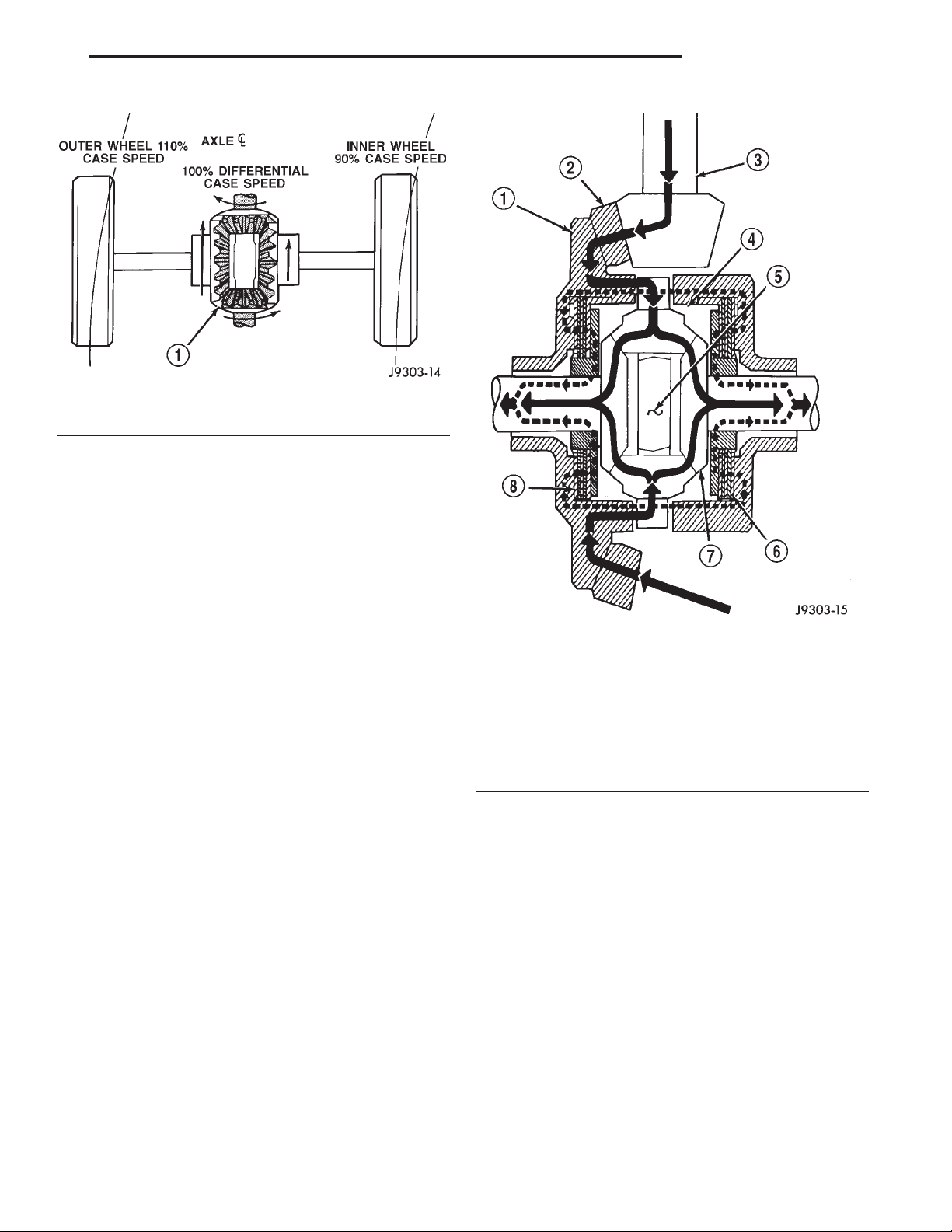
XJ 194 RBI AXLE 3 - 67
DESCRIPTION AND OPERATION (Continued)
Fig. 3 Differential Operation—On Turns
1 – PINION GEARS ROTATE ON PINION SHAFT
In the Trac-loky differential, part of the ring gear
torque is transmitted through clutch packs which
contain multiple discs. The clutches will have radial
grooves on the plates, and concentric grooves on the
discs or bonded fiber material that is smooth in
appearance.
OPERATION
In operation, the Trac-loky clutches are engaged
by two concurrent forces. The first being the preload
force exerted through Belleville spring washers
within the clutch packs. The second is the separating
forces generated by the side gears as torque is
applied through the ring gear (Fig. 4).
The Trac-loky design provides the differential
action needed for turning corners and for driving
straight ahead during periods of unequal traction.
When one wheel looses traction, the clutch packs
transfer additional torque to the wheel having the
most traction. Trac-loky differentials resist wheel
spin on bumpy roads and provide more pulling power
when one wheel looses traction. Pulling power is provided continuously until both wheels loose traction. If
both wheels slip due to unequal traction, Trac-loky
operation is normal. In extreme cases of differences
of traction, the wheel with the least traction may
spin.
DIAGNOSIS AND TESTING
GENERAL INFORMATION
Axle bearing problem conditions are usually caused
by:
• Insufficient or incorrect lubricant.
• Foreign matter/water contamination.
• Incorrect bearing preload torque adjustment.
Fig. 4 Trac-lokYLimited Slip Differential Operation
1 – CASE
2 – RING GEAR
3 – DRIVE PINION
4 – PINION GEAR
5 – MATE SHAFT
6 – CLUTCH PACK
7 – SIDE GEAR
8 – CLUTCH PACK
• Incorrect backlash.
Axle gear problem conditions are usually the result
of:
• Insufficient lubrication.
• Incorrect or contaminated lubricant.
• Overloading (excessive engine torque) or exceed-
ing vehicle weight capacity.
• Incorrect clearance or backlash adjustment.
Axle component breakage is most often the result
of:
• Severe overloading.
• Insufficient lubricant.
• Incorrect lubricant.
• Improperly tightened components.
• Differential housing bores not square to each
other.
Page 68
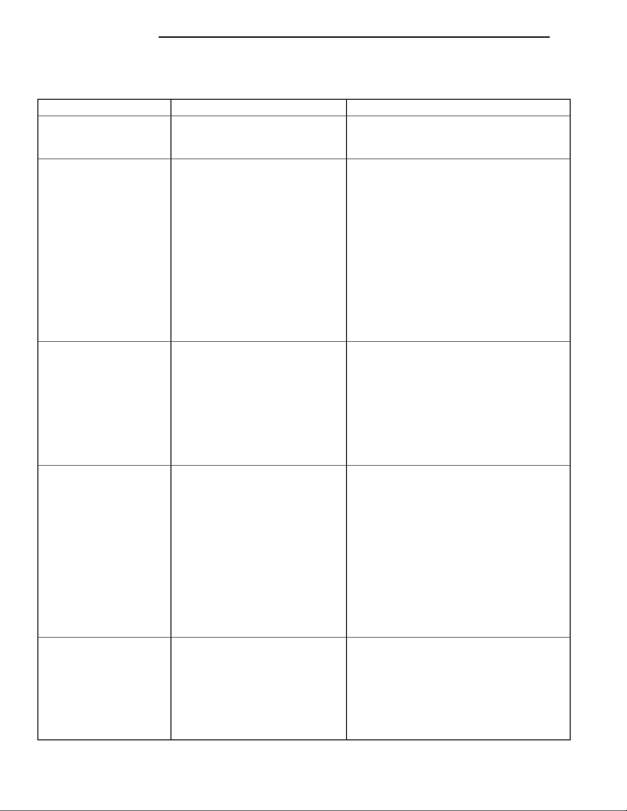
3 - 68 194 RBI AXLE XJ
DIAGNOSIS AND TESTING (Continued)
DIAGNOSTIC CHART
Condition Possible Causes Correction
Wheel Noise 1. Wheel loose. 1. Tighten loose nuts.
2. Faulty, brinelled wheel bearing. 2. Replace bearing.
Axle Shaft Noise 1. Misaligned axle tube. 1. Inspect axle tube alignment. Correct as
necessary.
2. Bent or sprung axle shaft. 2. Inspect and correct as necessary.
3. End-play in pinion bearings. 3. Refer to pinion pre-load information and
correct as necessary.
4. Excessive gear backlash
between the ring gear and pinion.
5. Improper adjustment of pinion
gear bearings.
6. Loose pinion yoke nut. 6. Tighten the pinion yoke nut.
7. Scuffed gear tooth contact
surfaces.
4. Check adjustment of the ring gear and
pinion backlash. Correct as necessary.
5. Adjust the pinion bearings pre-load.
7. Inspect and replace as necessary.
Axle Shaft Broke 1. Misaligned axle tube. 1. Replace the broken shaft after correcting
tube mis-alignment.
2 Vehicle overloaded. 2. Replace broken shaft and avoid excessive
weight on vehicle.
3. Erratic clutch operation. 3. Replace broken shaft and avoid or correct
erratic clutch operation.
4. Grabbing clutch. 4. Replace broken shaft and inspect and
repair clutch as necessary.
Differential Cracked 1. Improper adjustment of the
differential bearings.
2. Excessive ring gear backlash. 2. Replace case and inspect gears and
3. Vehicle overloaded. 3. Replace case and inspect gears and
4. Erratic clutch operation. 4. Replace case and inspect gears and
Differential Gears Scored 1. Insufficient lubrication. 1. Replace scored gears. Fill differential with
2. Improper grade of lubricant. 2. Replace scored gears. Fill differential with
3. Excessive spinning of one
wheel/tire.
1. Replace case and inspect gears and
bearings for further damage. Set differential
bearing pre-load properly.
bearings for further damage. Set ring gear
backlash properly.
bearings for further damage. Avoid excessive
vehicle weight.
bearings for further damage. Avoid erratic use
of clutch.
the correct fluid type and quantity.
the correct fluid type and quantity.
3. Replace scored gears. Inspect all gears,
pinion bores, and shaft for damage. Service
as necessary.
Page 69
XJ 194 RBI AXLE 3 - 69
DIAGNOSIS AND TESTING (Continued)
Condition Possible Causes Correction
Loss Of Lubricant 1. Lubricant level too high. 1. Drain lubricant to the correct level.
2. Worn axle shaft seals. 2. Replace seals.
3. Cracked differential housing. 3. Repair as necessary.
4. Worn pinion seal. 4. Replace seal.
5. Worn/scored yoke. 5. Replace yoke and seal.
6. Axle cover not properly sealed. 6. Remove, clean, and re-seal cover.
Axle Overheating 1. Lubricant level low. 1. Fill differential to correct level.
2. Improper grade of lubricant. 2. Fill differential with the correct fluid type
and quantity.
3. Bearing pre-loads too high. 3. Re-adjust bearing pre-loads.
4. Insufficient ring gear backlash. 4. Re-adjust ring gear backlash.
Gear Teeth Broke 1. Overloading. 1. Replace gears. Examine other gears and
bearings for possible damage.
2. Erratic clutch operation. 2. Replace gears and examine the remaining
parts for damage. Avoid erratic clutch
operation.
3. Ice-spotted pavement. 3. Replace gears and examine remaining
parts for damage.
4. Improper adjustments. 4. Replace gears and examine remaining
parts for damage. Ensure ring gear backlash
is correct.
Axle Noise 1. Insufficient lubricant. 1. Fill differential with the correct fluid type
and quantity.
2. Improper ring gear and pinion
adjustment.
3. Unmatched ring gear and pinion. 3. Replace gears with a matched ring gear
4. Worn teeth on ring gear and/or
pinion.
5. Loose pinion bearings. 5. Adjust pinion bearing pre-load.
6. Loose differential bearings. 6. Adjust differential bearing pre-load.
7. Mis-aligned or sprung ring gear. 7. Measure ring gear run-out. Replace
8. Loose differential bearing cap
bolts.
9. Housing not machined properly. 9. Replace housing.
2. Check ring gear and pinion contact pattern.
and pinion.
4. Replace ring gear and pinion.
components as necessary.
8. Inspect differential components and replace
as necessary. Ensure that the bearing caps
are torqued tot he proper specification.
Page 70
3 - 70 194 RBI AXLE XJ
DIAGNOSIS AND TESTING (Continued)
GEAR NOISE
Axle gear noise can be caused by insufficient lubricant, incorrect backlash, tooth contact, worn/damaged
gears, or the carrier housing not having the proper
offset and squareness.
Gear noise usually happens at a specific speed
range. The noise can also occur during a specific type
of driving condition. These conditions are acceleration, deceleration, coast, or constant load.
When road testing, first warm-up the axle fluid by
driving the vehicle at least 5 miles and then accelerate the vehicle to the speed range where the noise is
the greatest. Shift out-of-gear and coast through the
peak–noise range. If the noise stops or changes
greatly:
• Check for insufficient lubricant.
• Incorrect ring gear backlash.
• Gear damage.
Differential side gears and pinions can be checked
by turning the vehicle. They usually do not cause
noise during straight–ahead driving when the gears
are unloaded. The side gears are loaded during vehicle turns. A worn pinion mate shaft can also cause a
snapping or a knocking noise.
BEARING NOISE
The axle shaft, differential and pinion bearings can
all produce noise when worn or damaged. Bearing
noise can be either a whining, or a growling sound.
Pinion bearings have a constant–pitch noise. This
noise changes only with vehicle speed. Pinion bearing
noise will be higher pitched because it rotates at a
faster rate. Drive the vehicle and load the differential. If bearing noise occurs, the rear pinion bearing
is the source of the noise. If the bearing noise is
heard during a coast, the front pinion bearing is the
source.
Worn or damaged differential bearings usually produce a low pitch noise. Differential bearing noise is
similar to pinion bearing noise. The pitch of differential bearing noise is also constant and varies only
with vehicle speed.
Axle shaft bearings produce noise and vibration
when worn or damaged. The noise generally changes
when the bearings are loaded. Road test the vehicle.
Turn the vehicle sharply to the left and to the right.
This will load the bearings and change the noise
level. Where axle bearing damage is slight, the noise
is usually not noticeable at speeds above 30 mph.
LOW SPEED KNOCK
Low speed knock is generally caused by a worn
U–joint or by worn side–gear thrust washers. A worn
pinion shaft bore will also cause low speed knock.
VIBRATION
Vibration at the rear of the vehicle is usually
caused by a:
• Damaged drive shaft.
• Missing drive shaft balance weight(s).
• Worn or out–of–balance wheels.
• Loose wheel lug nuts.
• Worn U–joint(s).
• Loose/broken springs.
• Damaged axle shaft bearing(s).
• Loose pinion gear nut.
• Excessive pinion yoke run out.
• Bent axle shaft(s).
Check for loose or damaged front–end components
or engine/transmission mounts. These components
can contribute to what appears to be a rear–end
vibration. Do not overlook engine accessories, brackets and drive belts.
All driveline components should be examined
before starting any repair.
Refer to Group 22, Wheels and Tires, for additional
vibration information.
DRIVELINE SNAP
A snap or clunk noise when the vehicle is shifted
into gear (or the clutch engaged), can be caused by:
• High engine idle speed.
• Transmission shift operation.
• Loose engine/transmission/transfer case mounts.
• Worn U–joints.
• Loose spring mounts.
• Loose pinion gear nut and yoke.
• Excessive ring gear backlash.
• Excessive side gear to case clearance.
The source of a snap or a clunk noise can be determined with the assistance of a helper. Raise the vehicle on a hoist with the wheels free to rotate. Instruct
the helper to shift the transmission into gear. Listen
for the noise, a mechanics stethoscope is helpful in
isolating the source of a noise.
TRAC–LOKY DIFFERENTIAL NOISE
The most common problem is a chatter noise when
turning corners. Before removing a Trac-loky unit
for repair, drain, flush and refill the axle with the
specified lubricant. Refer to Lubricant change in this
Group.
A container of Mopart Trac-loky Lubricant (friction modifier) should be added after repair service or
during a lubricant change.
After changing the lubricant, drive the vehicle and
make 10 to 12 slow, figure-eight turns. This maneuver will pump lubricant through the clutches. This
will correct the condition in most instances. If the
chatter persists, clutch damage could have occurred.
Page 71
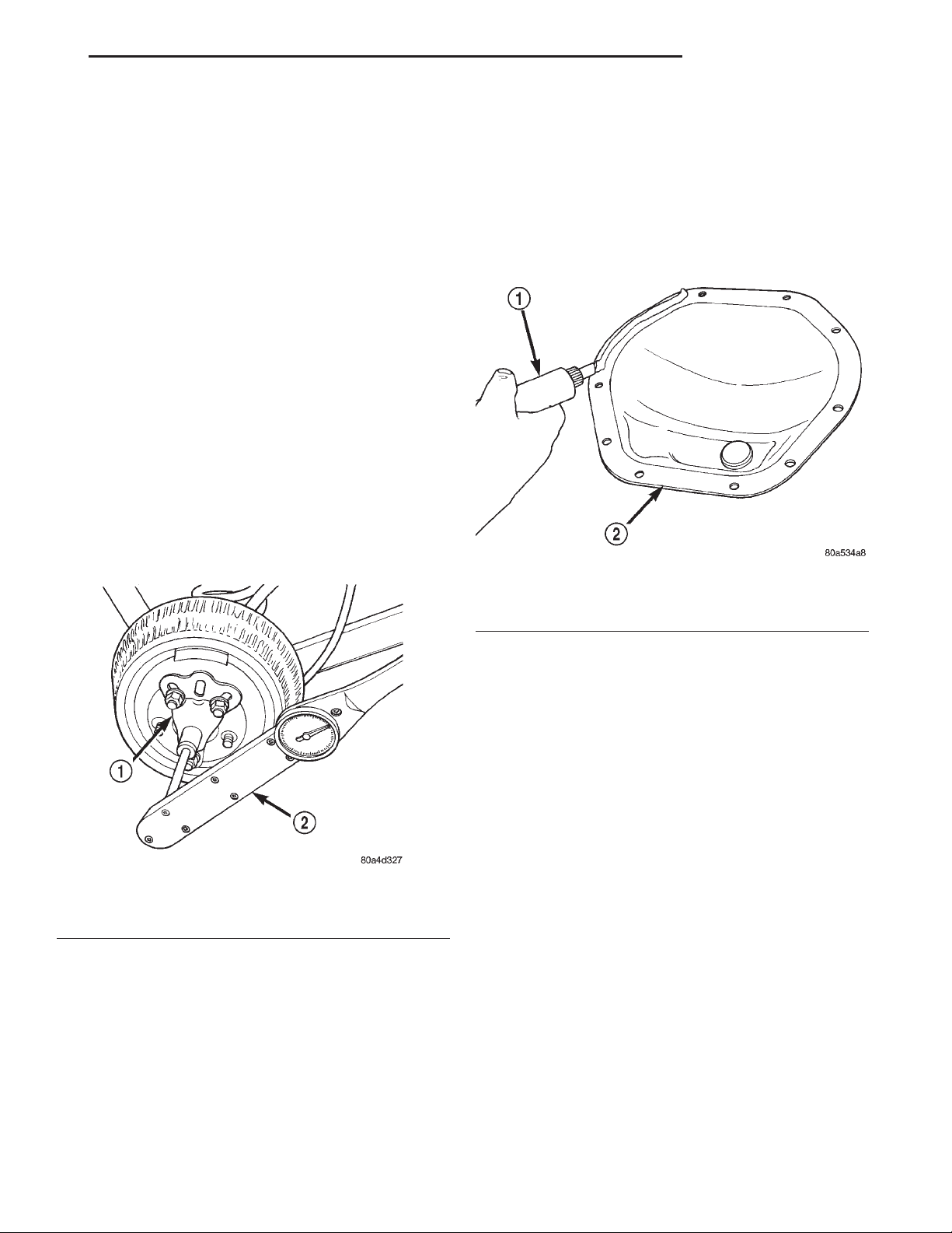
XJ 194 RBI AXLE 3 - 71
DIAGNOSIS AND TESTING (Continued)
TRAC–LOKY TEST
WARNING: WHEN SERVICING VEHICLES WITH A
TRAC–LOKY DIFFERENTIAL DO NOT USE THE
ENGINE TO TURN THE AXLE AND WHEELS. BOTH
REAR WHEELS MUST BE RAISED AND THE VEHICLE SUPPORTED. A TRAC–LOKY AXLE CAN
EXERT ENOUGH FORCE IF ONE WHEEL IS IN CONTACT WITH A SURFACE TO CAUSE THE VEHICLE
TO MOVE.
The differential can be tested without removing the
differential case by measuring rotating torque. Make
sure brakes are not dragging during this measurement.
(1) Place blocks in front and rear of both front
wheels.
(2) Raise one rear wheel until it is completely off
the ground.
(3) Engine off, transmission in neutral, and parking brake off.
(4) Remove wheel and bolt Special Tool 6790 to
studs.
(5) Use torque wrench on special tool to rotate
wheel and read rotating torque (Fig. 5).
(3) Remove the differential housing cover and
drain the lubricant from the housing.
(4) Clean the housing cavity with a flushing oil,
light engine oil, or lint free cloth. Do not use water,
steam, kerosene, or gasoline for cleaning.
(5) Remove the original sealant from the housing
and cover surfaces.
(6) Apply a bead of Mopart Silicone Rubber Seal-
ant, or equivalent, to the housing cover (Fig. 6).
Fig. 6 Apply Sealant
1 – SEALANT
2 – AXLE HOUSING COVER
Fig. 5 Trac-lokYTest —Typical
1 – SPECIAL TOOL 6790 WITH BOLT IN CENTER HOLE
2 – TORQUE WRENCH
(6) If rotating torque is less than 22 N·m (30 ft.
lbs.) or more than 271 N·m (200 ft. lbs.) on either
wheel the unit should be serviced.
SERVICE PROCEDURES
LUBRICANT CHANGE
(1) Raise and support the vehicle.
(2) Remove the lubricant fill hole plug from the
differential housing cover.
Install the housing cover within 5 minutes
after applying the sealant.
(7) Install the cover and any identification tag.
Tighten the cover bolts to 41 N·m (30 ft. lbs.) torque.
(8) For Trac–loky differentials, a quantity of
Mopart Trac–loky lubricant (friction modifier), or
equivalent, must be added after repair service or a
lubricant change. Refer to the Lubricant Specifications section of this group for the quantity necessary.
(9) Fill differential with Mopart Hypoid Gear
Lubricant, or equivalent, to bottom of the fill plug
hole. Refer to the Lubricant Specifications section of
this group for the quantity necessary.
CAUTION: Overfilling the differential can result in
lubricant foaming and overheating.
(10) Install the fill hole plug and lower the vehicle.
(11) Trac–loky differential equipped vehicles
should be road tested by making 10 to 12 slow figureeight turns. This maneuver will pump the lubricant
through the clutch discs to eliminate a possible chatter noise complaint.
Page 72
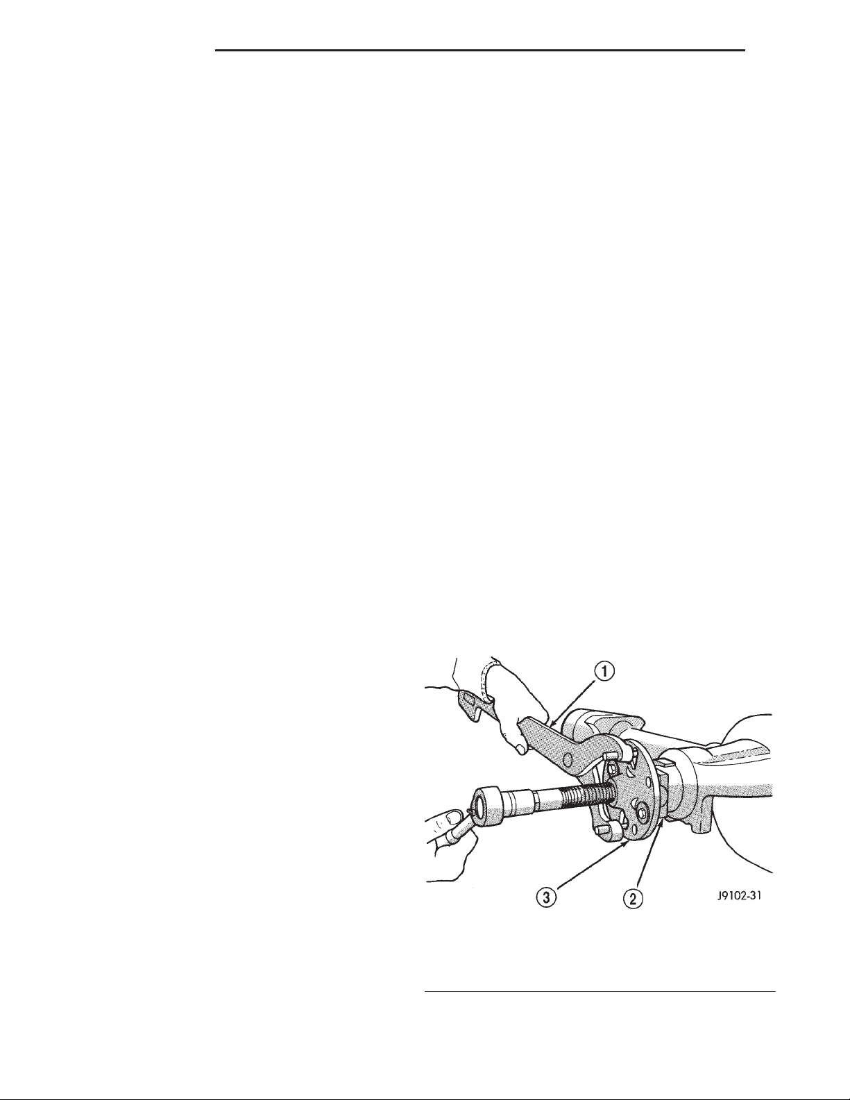
3 - 72 194 RBI AXLE XJ
REMOVAL AND INSTALLATION
REAR AXLE
REMOVAL
(1) Raise and support the vehicle.
(2) Position a suitable lifting device under the
axle.
(3) Secure axle to device.
(4) Remove the wheels and tires.
(5) Remove the brake drums from the axle. Refer
to Group 5, Brakes, for proper procedures.
(6) Disconnect parking brake cables from brackets
and lever.
(7) Remove wheel speed sensors, if necessary.
Refer to Group 5, Brakes, for proper procedures.
(8) Disconnect the brake hose at the axle junction
block. Do not disconnect the brake hydraulic lines at
the wheel cylinders. Refer to Group 5, Brakes, for
proper procedures.
(9) Disconnect the vent hose from the axle shaft
tube.
(10) Mark the propeller shaft and yokes for installation alignment reference.
(11) Remove propeller shaft.
(12) Disconnect stabilizer bar links.
(13) Disconnect shock absorbers from axle.
(14) Remove the U-bolts which hold the axle to the
spring brackets.
(15) Separate the axle from the vehicle.
INSTALLATION
NOTE: The weight of the vehicle must be supported by the springs before suspension arms and
track bar fasteners can be tightened. If the springs
are not at their normal ride position, vehicle ride
height and handling could be affected.
(8) Connect the brake hose to the axle junction
block. Refer to Group 5, Brakes, for proper procedures.
(9) Install axle vent hose.
(10) Align propeller shaft and pinion yoke reference marks. Install U-joint straps and bolts. Tighten
to 19 N·m (14 ft. lbs.) torque.
(11) Install the wheels and tires.
(12) Add gear lubricant, if necessary. Refer to
Lubricant Specifications in this section for lubricant
requirements.
(13) Remove lifting device from axle and lower the
vehicle.
PINION SHAFT SEAL
REMOVAL
(1) Raise and support the vehicle.
(2) Remove wheel and tire assemblies.
(3) Remove the brake drums. Refer to Group 5,
Brakes, for proper procedures.
(4) Mark the propeller shaft and pinion yoke for
installation alignment reference.
(5) Remove the propeller shaft from the yoke.
(6) Rotate the pinion gear three or four times.
(7) Measure the amount of torque necessary to
rotate the pinion gear with a (in. lbs.) dial-type
torque wrench. Record the torque reading for installation reference.
(8) Using Holder 6958 to hold the pinion yoke,
remove the pinion nut and washer.
(9) Use Remover C-452 and Wrench C-3281 to
remove the pinion yoke (Fig. 7).
(1) Raise the axle with lifting device and align the
spring centering bolts with the mating holes in the
axle spring perch.
(2) Install the U-bolts which hold the axle to the
spring brackets. Tighten nuts to 70 N·m (52 ft. lbs.).
(3) Install shock absorbers and tighten nuts to 60
N·m (44 ft. lbs.) torque.
(4) Install stabilizer bar links and tighten nuts to
74 N·m (55 ft. lbs.) torque.
(5) Install the wheel speed sensors, if necessary.
Refer to Group 5, Brakes, for proper procedures.
(6) Connect parking brake cable to brackets and
lever.
(7) Install the brake drums. Refer to Group 5,
Brakes, for proper procedures.
Fig. 7 Pinion Yoke Removal
1 – SPECIAL TOOL C-3281
2 – YOKE
3 – SPECIAL TOOL C-452
Page 73
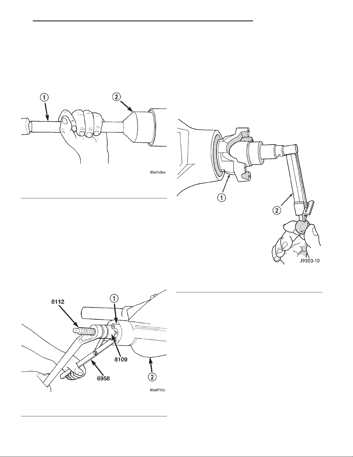
XJ 194 RBI AXLE 3 - 73
REMOVAL AND INSTALLATION (Continued)
(10) Use a suitable pry tool or slide hammer
mounted screw to remove the pinion gear seal.
INSTALLATION
(1) Apply a light coating of gear lubricant on the
lip of pinion seal. Install seal with Installer C-3972-A
and Handle C-4171 (Fig. 8).
Fig. 8 Pinion Seal Installation
1 – SPECIAL TOOL C-4171
2 – SPECIAL TOOL C-3972–A
(2) Install yoke on the pinion gear with Screw
8112, Cup 8109, and Holder 6958 (Fig. 9).
CAUTION: Never loosen pinion gear nut to
decrease pinion gear bearing rotating torque and
never exceed specified preload torque. If preload
torque or rotating torque is exceeded a new collapsible spacer must be installed. The torque
sequence will then have to be repeated.
(5) Rotate the pinion shaft using a (in. lbs.) torque
wrench. Rotating torque should be equal to the reading recorded during removal plus an additional 0.56
N·m (5 in. lbs.) (Fig. 10).
CAUTION: Do not exceed the minimum tightening
torque when installing the pinion yoke at this point.
Damage to the collapsible spacer or bearings may
result.
(3) Install the yoke washer and a new nut on the
pinion gear and tighten the pinion nut until there is
zero bearing end-play.
(4) Tighten the nut to 271 N·m (200 ft. lbs.).
Fig. 9 Pinion Yoke Installation
1 – PINION YOKE
2 – AXLE HOUSING
Fig. 10 Check Pinion Rotation Torque
1 – PINION YOKE
2 – INCH POUND TORQUE WRENCH
(6) If the rotating torque is low, use Holder 6958 to
hold the pinion yoke (Fig. 11), and tighten the pinion
shaft nut in 6.8 N·m (5 ft. lbs.) increments until the
proper rotating torque is achieved.
CAUTION: If the maximum tightening torque is
reached prior to reaching the required rotating
torque, the collapsible spacer may have been damaged. Replace the collapsible spacer.
(7) Align the installation reference marks on the
propeller shaft and yoke and install the propeller
shaft.
(8) Add gear lubricant to the differential housing,
if necessary. Refer to the Lubricant Specifications for
gear lubricant requirements.
(9) Install the brake drums. Refer to Group 5,
Brakes, for proper procedures.
(10) Install wheel and tire assemblies.
Page 74
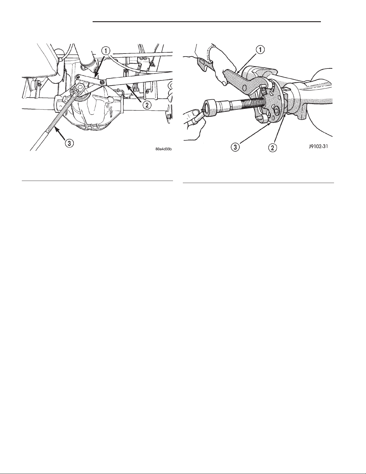
3 - 74 194 RBI AXLE XJ
REMOVAL AND INSTALLATION (Continued)
Fig. 11 Tightening Pinion Shaft Nut–Typical
1 – SPECIAL TOOL 6958
2 – 1 in. PIPE
3 – 3/4 DRIVE TORQUE WRENCH
(11) Lower the vehicle.
COLLAPSIBLE SPACER
REMOVAL W/PINION INSTALLED
(1) Raise and support the vehicle.
(2) Remove wheel and tire assemblies.
(3) Remove rear brake drums. Refer to Group 5,
Brakes, for proper procedures.
(4) Mark the propeller shaft and pinion yoke for
installation reference.
(5) Remove the propeller shaft from the yoke.
(6) Rotate the pinion gear three or four times.
(7) Measure the amount of torque necessary to
rotate the pinion gear with a (in. lbs.) dial-type
torque wrench. Record the torque reading for installation reference.
(8) Using Holder 6958 to hold the pinion yoke,
remove the pinion nut and washer.
(9) Use Remover C-452 and Wrench C-3281 to
remove the pinion yoke (Fig. 12).
(10) Use a suitable pry tool or a slide hammer
mounted screw to remove the pinion shaft seal.
Remove the front pinion bearing using a pair of
(11)
suitable pick tools to pull the bearing straight off the
pinion gear shaft. It may be necessary to lightly tap the
end of the pinion gear with a rawhide or rubber mallet
if the bearing becomes bound on the pinion shaft.
(12) Remove the collapsible spacer.
REMOVAL W/PINION REMOVED
(1) Raise and support the vehicle.
(2) Remove wheel and tire assemblies.
(3) Remove rear brake drums. Refer to Group 5,
Brakes, for proper procedures.
Fig. 12 Pinion Yoke Removal
1 – SPECIAL TOOL C-3281
2 – YOKE
3 – SPECIAL TOOL C-452
(4) Mark the propeller shaft and pinion yoke for
installation reference.
(5) Remove the propeller shaft from the yoke.
(6) Rotate the pinion gear three or four times.
(7) Measure the amount of torque necessary to
rotate the pinion gear with a (in. lbs.) dial-type
torque wrench. Record the torque reading for installation reference.
(8) Remove differential assembly from axle housing.
(9) Using Holder 6958 to hold yoke, remove the
pinion yoke nut and washer.
(10) Using Remover C–452 and Wrench C–3281,
remove the pinion yoke from pinion shaft (Fig. 12).
(11) Remove the pinion gear from housing (Fig.
13). Catch the pinion with your hand to prevent it
from falling and being damaged.
(12) Remove collapsible spacer from pinion shaft.
INSTALLATION
(1) Install a new collapsible preload spacer on pinion shaft (Fig. 14).
(2) If pinion gear was removed, install pinion gear
in housing.
(3) Install pinion front bearing, if necessary.
(4) Apply a light coating of gear lubricant on the
lip of pinion seal. Install seal with Installer C-3972-A
and Handle C–4171 (Fig. 15).
(5) Install yoke with Screw 8112, Cup 8109, and
Holder 6958 (Fig. 16).
(6) If the original pinion bearings are being used,
install differential assembly and axle shafts, if necessary.
Page 75
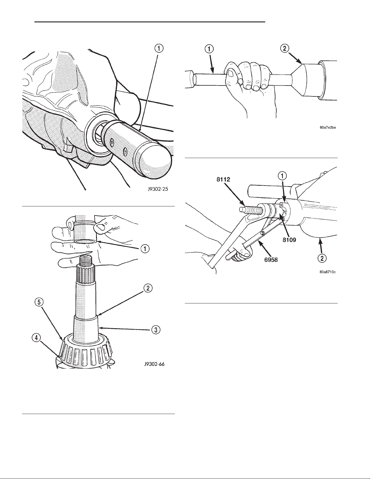
XJ 194 RBI AXLE 3 - 75
REMOVAL AND INSTALLATION (Continued)
Fig. 15 Pinion Seal Installation
1 – SPECIAL TOOL C-4171
2 – SPECIAL TOOL C-3972–A
Fig. 13 Remove Pinion Gear
1 – RAWHIDE HAMMER
Fig. 14 Collapsible Preload Spacer
1 – COLLAPSIBLE SPACER
2 – SHOULDER
3 – PINION GEAR
4 – OIL SLINGER
5 – REAR BEARING
NOTE: If new pinion bearings were installed, do not
install the differential assembly and axle shafts until
after the pinion bearing preload and rotating torque
are set.
Fig. 16 Pinion Yoke Installation
1 – PINION YOKE
2 – AXLE HOUSING
(7) Install the yoke washer and a new nut on the
pinion gear. Tighten the pinion nut until there is zero
bearing end-play.
(8) Tighten the nut to 271 N·m (200 ft. lbs.).
CAUTION: Never loosen pinion gear nut to
decrease pinion gear bearing rotating torque and
never exceed specified preload torque. If preload
torque or rotating torque is exceeded a new collapsible spacer must be installed. The torque
sequence will then have to be repeated.
(9) Using yoke holder 6958 and a torque wrench
set at 474 N·m (350 ft. lbs.), crush collapsible spacer
until bearing end play is taken up (Fig. 17).
NOTE: If more than 474 N·m (350 ft. lbs.) of torque
is necessary to remove the bearing end play, the
collapsible spacer is defective and must be
replaced.
Page 76
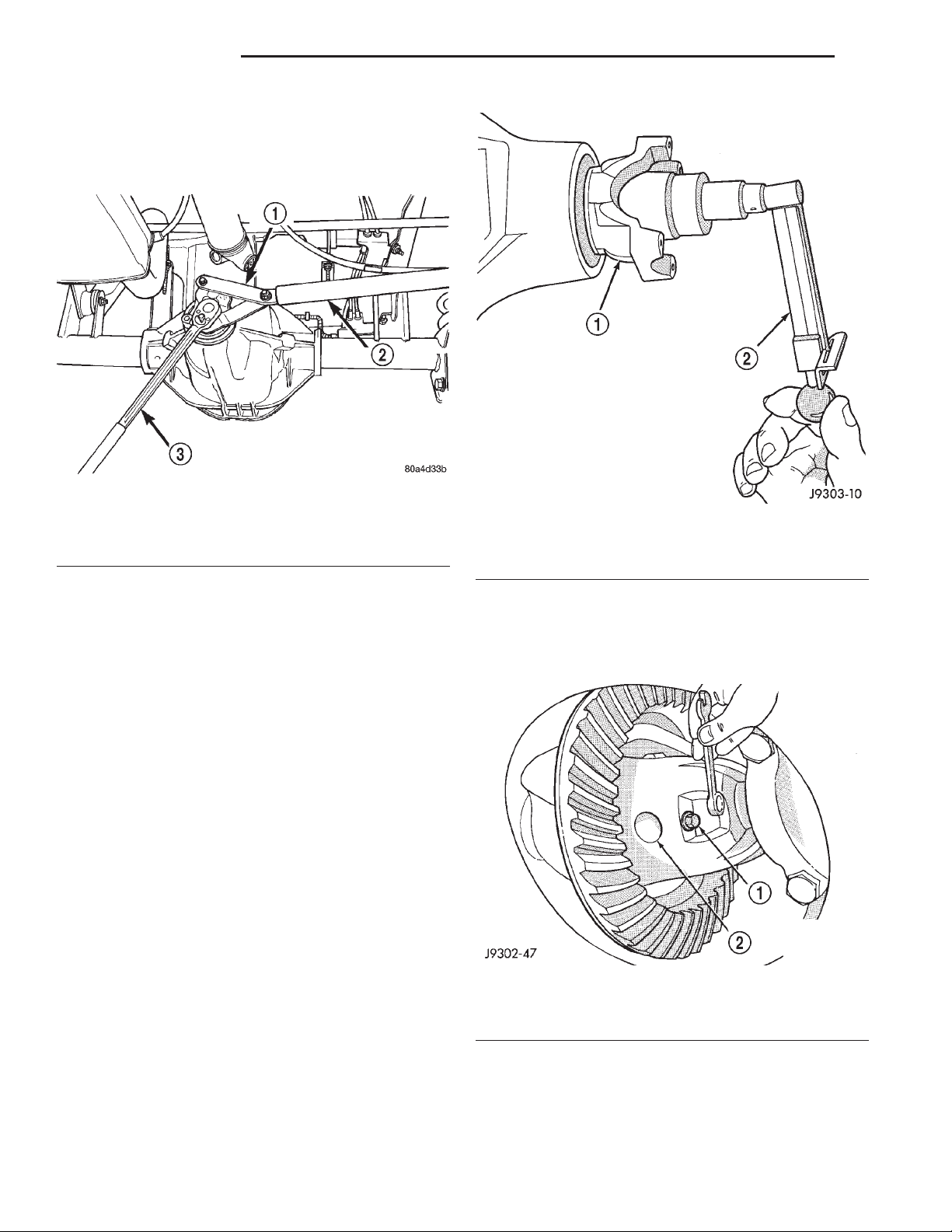
3 - 76 194 RBI AXLE XJ
REMOVAL AND INSTALLATION (Continued)
(10) Slowly tighten the nut in 6.8 N·m (5 ft. lbs.)
increments until the rotating torque is achieved.
Measure the rotating torque frequently to avoid over
crushing the collapsible spacer (Fig. 18).
Fig. 17 Tightening Pinion Nut–Typical
1 – SPECIAL TOOL 6958
2 – 1 in. PIPE
3 – 3/4 DRIVE TORQUE WRENCH
Fig. 18 Check Pinion Gear Rotation Torque
1 – PINION YOKE
2 – INCH POUND TORQUE WRENCH
(11) Check rotating torque with a (in. lbs.) torque
wrench (Fig. 18). The torque necessary to rotate the
pinion gear should be:
• Original Bearings — The reading recorded dur-
ing removal, plus an additional 0.56 N·m (5 in. lbs.).
• New Bearings — 1.5 to 4 N·m (15 to 35 in. lbs.).
(12) Install differential assembly and axle shafts,
if necessary.
(13) Align marks made previously on yoke and
propeller shaft and install propeller shaft.
(14) Install rear brake drums. Refer to Group 5,
Brakes, for proper procedures.
(15) Add gear lubricant, if necessary. Refer to
Lubricant Specifications of this section for lubricant
requirements.
(16) Install wheel and tire assemblies.
(17) Lower vehicle.
AXLE SHAFT
REMOVAL
(1) Raise and support vehicle. Ensure that the
transmission is in neutral.
(2) Remove wheel and tire assembly.
(3) Remove brake drum. Refer to Group 5, Brakes,
for proper procedure.
(4) Clean all foreign material from housing cover
area.
(5) Loosen housing cover bolts. Drain lubricant
from the housing and axle shaft tubes. Remove housing cover.
(6) Rotate differential case so that pinion mate
gear shaft lock screw is accessible. Remove lock
screw and pinion mate gear shaft from differential
case (Fig. 19).
Fig. 19 Mate Shaft Lock Screw
1 – LOCK SCREW
2 – PINION GEAR MATE SHAFT
(7) Push axle shaft inward and remove axle shaft
C–clip lock from the axle shaft (Fig. 20).
(8) Remove axle shaft. Use care to prevent damage
to axle shaft bearing and seal, which will remain in
axle shaft tube. Also, exercise care not to damage the
Page 77
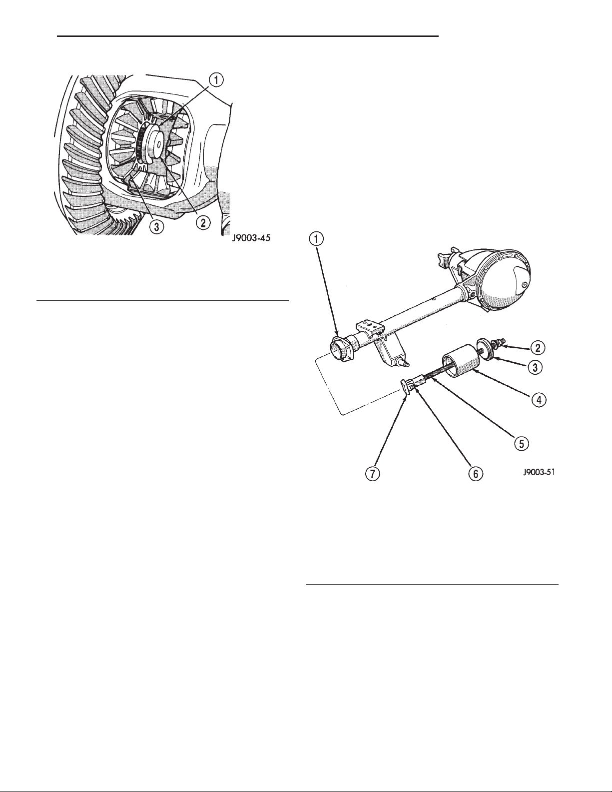
XJ 194 RBI AXLE 3 - 77
REMOVAL AND INSTALLATION (Continued)
AXLE SHAFT SEAL AND BEARING
REMOVAL
(1) Remove the axle shaft.
(2) Remove the axle shaft seal from the end of the
axle shaft tube with a small pry bar.
NOTE: The seal and bearing can be removed at the
same time with the bearing removal tool.
(3) Remove the axle shaft bearing from the axle
tube with Bearing Removal Tool Set 6310 using
Adapter Foot 6310-5 (Fig. 21).
Fig. 20 Axle Shaft C–Clip Lock
1 – C-CLIP LOCK
2 – AXLE SHAFT
3 – SIDE GEAR
wheel speed sensor on vehicles equipped with ABS
brakes.
(9) Inspect axle shaft seal for leakage or damage.
(10) Inspect roller bearing contact surface on axle
shaft for signs of brinelling, galling and pitting. If
any of these conditions exist, the axle shaft and/or
bearing and seal must be replaced.
INSTALLATION
(1) Lubricate bearing bore and seal lip with gear
lubricant. Insert axle shaft through seal, bearing,
and engage it into side gear splines.
NOTE: Use care to prevent shaft splines from damaging axle shaft seal lip. Also, exercise care not to
damage the wheel speed sensor on vehicles
equipped with ABS brakes
(2) Insert C–clip lock in end of axle shaft. Push
axle shaft outward to seat C–clip lock in side gear.
(3) Insert pinion mate shaft into differential case
and through thrust washers and pinion gears.
(4) Align hole in shaft with hole in the differential
case and install lock screw with Loctitet on the
threads. Tighten lock screw to 19 N·m (14 ft. lbs.)
torque.
(5) Install cover and add fluid. Refer to Lubricant
Change procedure in this section for procedure and
lubricant requirements.
(6) Install brake drum. Refer to Group 5, Brakes,
for proper procedures.
(7) Install wheel and tire.
(8) Lower vehicle.
Fig. 21 Axle Shaft Bearing Removal
1 – AXLE SHAFT TUBE
2 – NUT
3 – GUIDE PLATE
4 – GUIDE
5 – THREADED ROD
6 – ADAPTER
7 – FOOT
(4) Inspect the axle shaft tube bore for roughness
and burrs. Remove as necessary.
INSTALLATION
Do not install the original axle shaft seal.
Always install a new seal.
(1) Wipe the axle shaft tube bore clean.
(2) Install axle shaft bearing with Installer 6436
and Handle C–4171. Ensure that the part number on
the bearing is against the installer.
(3) Install the new axle shaft seal with Installer
6437 and Handle C–4171 (Fig. 22).
Page 78
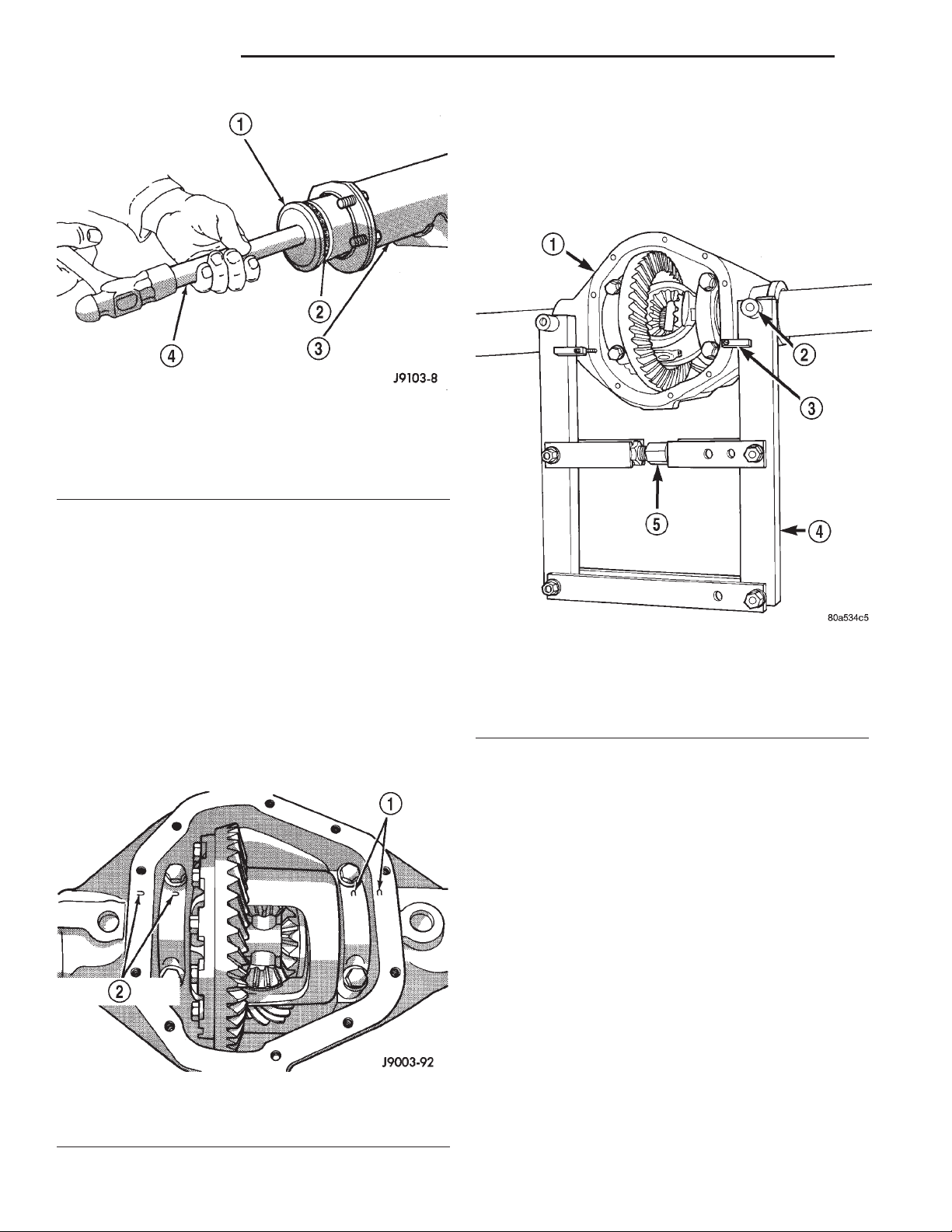
3 - 78 194 RBI AXLE XJ
REMOVAL AND INSTALLATION (Continued)
(6) Loosen the differential bearing cap bolts.
(7) Position Spreader W–129–B, utilizing some
items from Adapter set 6987, with the tool dowel pins
seated in the locating holes (Fig. 24). Install the holddown clamps and tighten the tool turnbuckle finger–
tight.
Fig. 22 Axle Shaft Seal Installation
1 – SPECIAL TOOL 6437
2 – SEAL
3 – AXLE SHAFT TUBE
4 – SPECIAL TOOL C-4171
(4) Install the axle shaft.
DIFFERENTIAL
REMOVAL
(1) Raise and support vehicle.
(2) Remove the lubricant fill hole plug from the
differential housing cover.
(3) Remove the differential housing cover and
allow fluid to drain.
(4) Remove axle shafts.
(5) Note the installation reference letters stamped
on the bearing caps and housing machined sealing
surface (Fig. 23).
Fig. 23 Bearing Cap Identification
1 – INSTALLATION REFERENCE LETTERS
2 – INSTALLATION REFERENCE LETTERS
Fig. 24 Install Axle Housing Spreader
1 – AXLE HOUSING
2 – DOWEL
3 – SAFETY HOLD DOWN
4 – SPECIAL TOOL W-129–B
5 – TURNBUCKLE
(8) Install a Pilot Stud C-3288-B at the left side of
the differential housing. Attach Dial Indicator C-3339
to pilot stud. Load the indicator plunger against the
opposite side of the housing (Fig. 25) and zero the
indicator.
CAUTION: Do not spread over 0.38 mm (0.015 in). If
the housing is over–spread, it could be distorted or
damaged.
(9) Spread the housing enough to remove the differential case from the housing. Measure the distance with the dial indicator (Fig. 26).
(10) Remove the dial indicator.
(11) While holding the differential case in position,
remove the differential bearing cap bolts and caps.
(12) Remove the differential from the housing.
Ensure that the differential bearing cups remain in
position on the differential bearings (Fig. 27).
(13) Mark or tag the differential bearing cups to
indicate which side of the differential they were
removed from.
Page 79
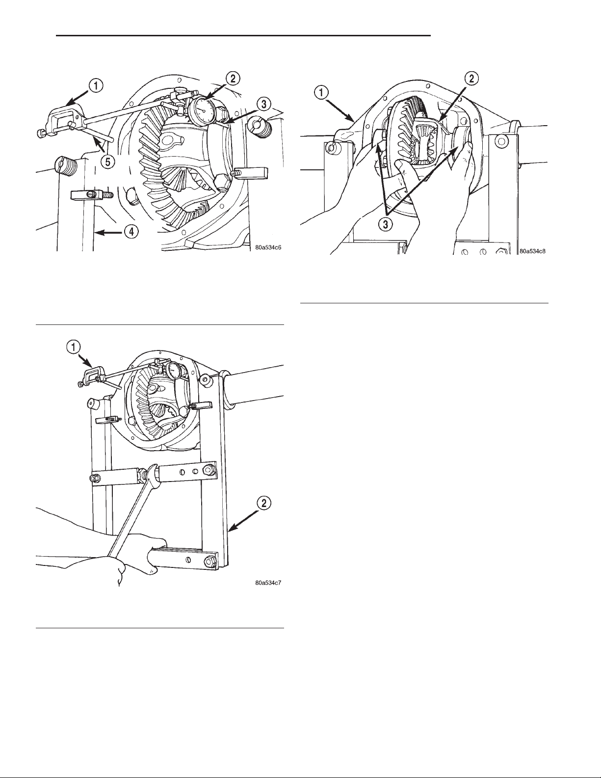
XJ 194 RBI AXLE 3 - 79
REMOVAL AND INSTALLATION (Continued)
Fig. 25 Install Dial Indicator
1 – SPECIAL TOOLC-3339
2 – DIAL INDICATOR
3 – LEVER ADAPTER
4 – SPECIAL TOOL W-129–B
5 – SPECIAL TOOL C-3288–B
Fig. 27 Differential Case Removal
1 – AXLE HOUSING
2 – DIFFERENTIAL CASE
3 – BEARING CUPS
INSTALLATION
If replacement differential bearings or differential
case are being installed, differential side bearing
shim requirements may change. Refer to the Differential Bearing Preload and Gear Backlash procedures in this section to determine the proper shim
selection.
Position Spreader W–129–B, utilizing some items
(1)
from Adapter set 6987, with the tool dowel pins seated
in the locating holes (Fig. 28). Install the holddown
clamps and tighten the tool turnbuckle finger–tight.
(2) Install a Pilot Stud C-3288-B at the left side of
the differential housing. Attach Dial Indicator C-3339
to pilot stud. Load the indicator plunger against the
opposite side of the housing (Fig. 25) and zero the
indicator.
CAUTION: Do not spread over 0.38 mm (0.015 in). If
the housing is over–spread, it could be distorted or
damaged.
Fig. 26 Spread Axle Housing
1 – SPECIAL TOOL C-3339
2 – SPECIAL TOOL W-129–B
(14) Retrieve differential case preload shims from
axle housing. Mark or tag the differential case preload shims to indicate which side of the differential
they were removed from.
(15) Remove spreader from housing.
(3) Spread the housing enough to install the case
in the housing. Measure the distance with the dial
indicator (Fig. 26).
(4) Remove the dial indicator.
(5) Install differential case in the housing. Ensure
that the differential bearing cups remain in position
on the differential bearings and that the preload
shims remain between the face of the bearing cup
and the housing. Tap the differential case to ensure
the bearings cups and shims are fully seated in the
housing.
(6) Install the bearing caps at their original locations (Fig. 29).
(7) Loosely install differential bearing cap bolts.
(8) Remove axle housing spreader.
Page 80
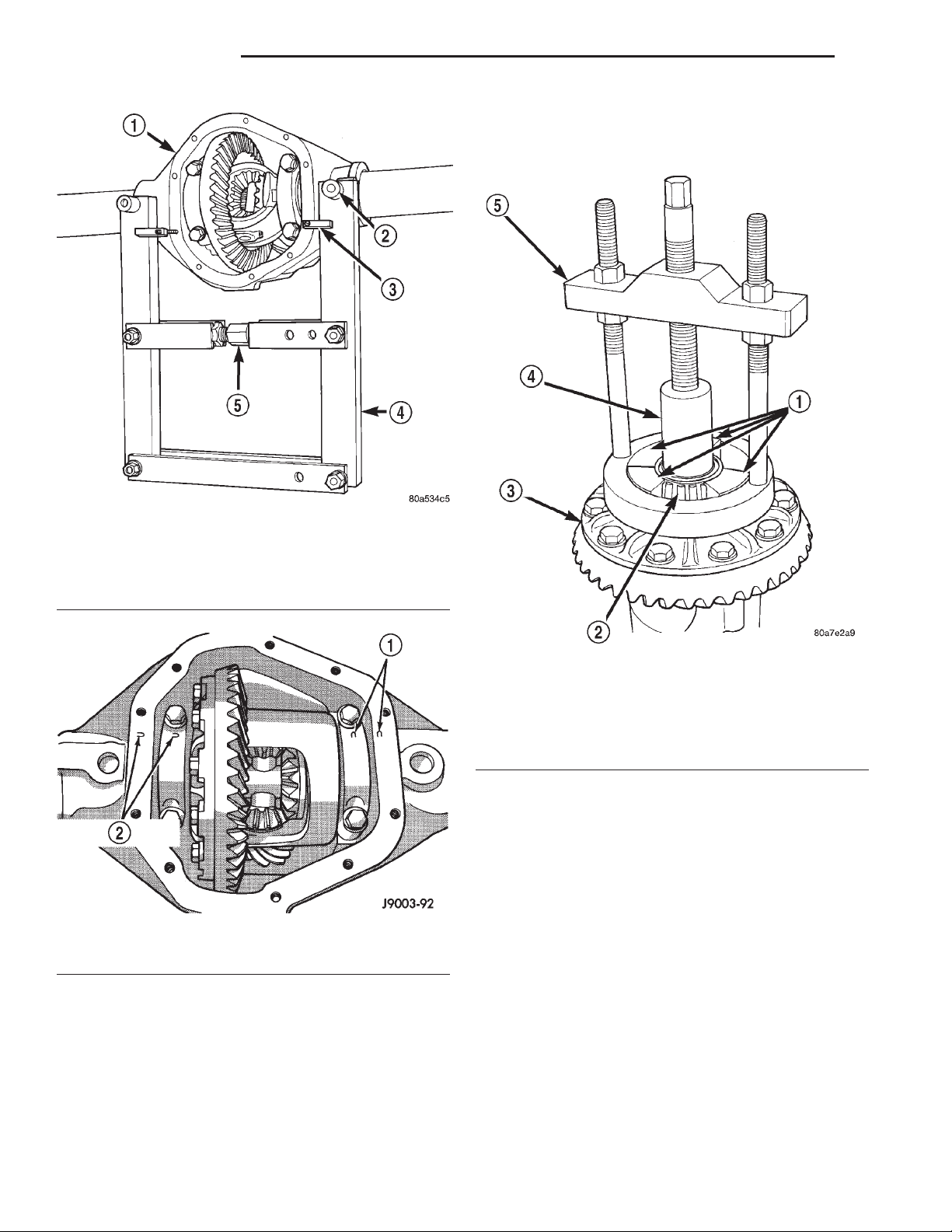
3 - 80 194 RBI AXLE XJ
REMOVAL AND INSTALLATION (Continued)
(2) Remove the bearings from the differential case
with Puller/Press C-293-PA, C-293-39 Blocks, and
Plug SP-3289 (Fig. 30).
Fig. 28 Install Axle Housing Spreader
1 – AXLE HOUSING
2 – DOWEL
3 – SAFETY HOLD DOWN
4 – SPECIAL TOOL W-129–B
5 – TURNBUCKLE
Fig. 29 Differential Bearing Cap Reference Letters
1 – INSTALLATION REFERENCE LETTERS
2 – INSTALLATION REFERENCE LETTERS
Fig. 30 Differential Bearing Removal
1 – SPECIAL TOOL C-293–39
2 – BEARING
3 – DIFFERENTIAL
4 – SPECIAL TOOL SP-3289
5 – SPECIAL TOOL C-293–PA
INSTALLATION
(1) Using tool C-3716-A with handle C-4171,
install differential side bearings (Fig. 31).
(2) Install differential in axle housing.
RING GEAR
NOTE: The ring gear and pinion are serviced as a
matched set. Do not replace the ring gear without
replacing the pinion.
(9) Tighten the bearing cap bolts to 77 N·m (57 ft.
lbs.) torque.
(10) Install the axle shafts.
DIFFERENTIAL SIDE BEARINGS
REMOVAL
(1) Remove differential from axle housing.
REMOVAL
(1) Remove differential from axle housing.
(2) Place differential case in a suitable vise with
soft metal jaw protectors. (Fig. 32)
(3) Remove bolts holding ring gear to differential
case.
(4) Using a soft hammer, drive ring gear from differential case (Fig. 32).
Page 81
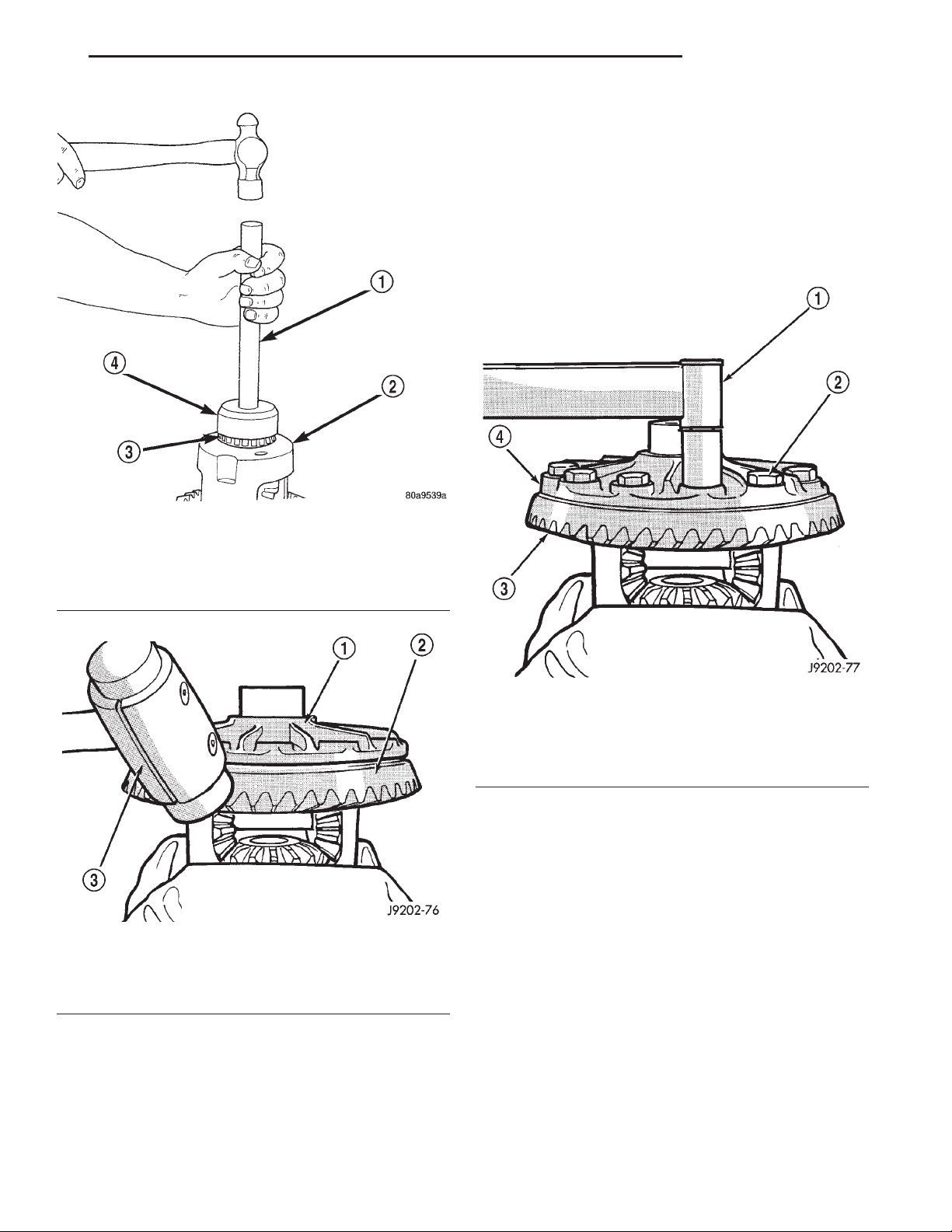
XJ 194 RBI AXLE 3 - 81
REMOVAL AND INSTALLATION (Continued)
(1) Invert the differential case and start two ring
gear bolts. This will provide case-to-ring gear bolt
hole alignment.
(2) Invert the differential case in the vise.
(3) Install new ring gear bolts and alternately
tighten to 95–122 N·m (70–90 ft. lbs.) torque (Fig.
33).
(4) Install differential in axle housing and verify
gear mesh and contact pattern.
Fig. 31 Install Differential Side Bearings
1 – HANDLE C-4171
2 – DIFFERENTIAL
3 – BEARING
4 – TOOL C-3716–A
Fig. 32 Ring Gear Removal
1 – CASE
2 – RING GEAR
3 – RAWHIDE HAMMER
INSTALLATION
CAUTION: Do not reuse the bolts that held the ring
gear to the differential case. The bolts can fracture
causing extensive damage.
Fig. 33 Ring Gear Bolt Installation
1 – TORQUE WRENCH
2 – RING GEAR BOLT
3 – RING GEAR
4 – CASE
PINION GEAR
The ring and pinion gears are serviced in a
matched set. Do not replace the pinion gear without
replacing the ring gear.
REMOVAL
(1) Remove differential from the axle housing.
(2) Mark pinion yoke and propeller shaft for
installation alignment.
(3) Disconnect propeller shaft from pinion yoke.
Using suitable wire, tie propeller shaft to underbody.
(4) Using Holder 6958 to hold yoke, remove the
pinion yoke nut and washer.
(5) Using Remover C–452 and Wrench C–3281,
remove the pinion yoke from pinion shaft (Fig. 34).
(6) Remove the pinion gear from housing (Fig. 35).
Catch the pinion with your hand to prevent it from
falling and being damaged.
Page 82
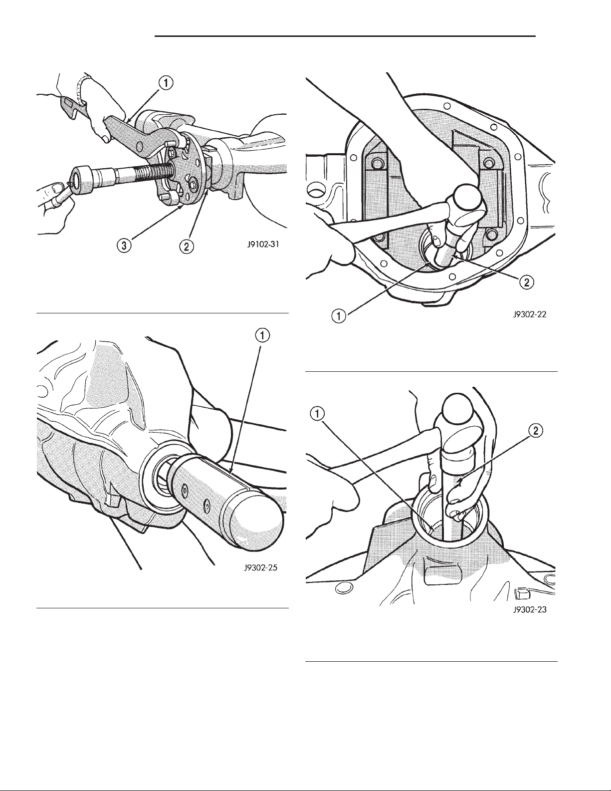
3 - 82 194 RBI AXLE XJ
REMOVAL AND INSTALLATION (Continued)
Fig. 34 Pinion Yoke Removal
1 – SPECIAL TOOL C-3281
2 – YOKE
3 – SPECIAL TOOL C-452
Fig. 35 Remove Pinion Gear
1 – RAWHIDE HAMMER
(7) Use a suitable pry tool or a slide hammer
mounted screw to remove the pinion shaft seal.
(8) Remove oil slinger, if equipped, and front pin-
ion bearing.
(9) Remove the front pinion bearing cup with
Remover C-4345 and Handle C–4171 (Fig. 36).
(10) Remove the rear bearing cup from housing
(Fig. 37). Use Remover D-149 and Handle C–4171.
(11) Remove the collapsible preload spacer (Fig.
38).
Fig. 36 Front Bearing Cup Removal
1 – REMOVER
2 – HANDLE
Fig. 37 Rear Bearing Cup Removal
1 – DRIVER
2 – HANDLE
(12) Remove the rear bearing from the pinion with
Puller/Press C-293-PA and Adapters C-293-40 (Fig.
39).
Place 4 adapter blocks so they do not damage
the bearing cage.
Page 83
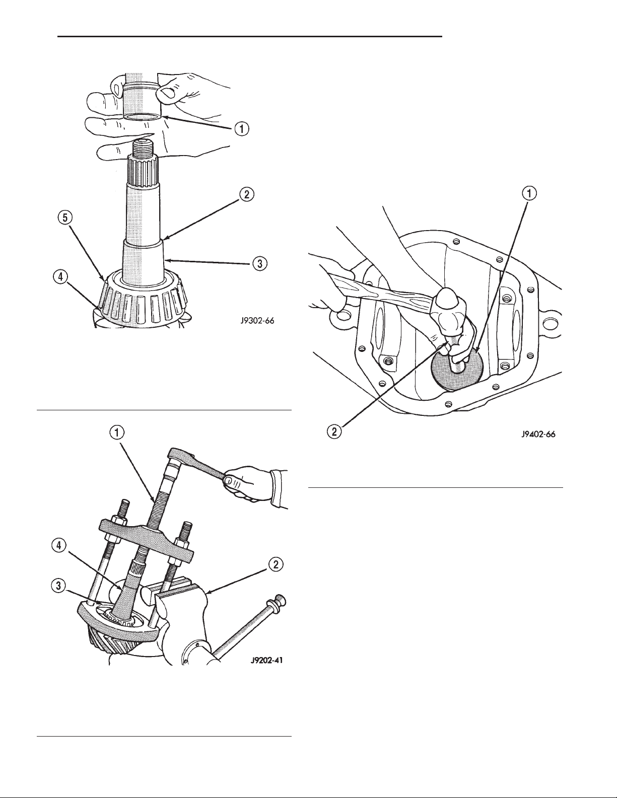
XJ 194 RBI AXLE 3 - 83
REMOVAL AND INSTALLATION (Continued)
(13) Remove the depth shims from the pinion gear
shaft. Record the thickness of the depth shims.
INSTALLATION
(1) Apply Mopart Door Ease, or equivalent, stick
lubricant to outside surface of bearing cup.
(2) Install the pinion rear bearing cup with
Installer D-146 and Driver Handle C–4171 (Fig. 40).
Ensure cup is correctly seated.
Fig. 38 Collapsible Spacer
1 – COLLAPSIBLE SPACER
2 – SHOULDER
3 – PINION GEAR
4 – OIL SLINGER
5 – REAR BEARING
Fig. 39 Rear Bearing Removal
1 – SPECIAL TOOL C-293–PA
2 – VISE
3 – ADAPTERS
4 – DRIVE PINION GEAR SHAFT
Fig. 40 Pinion Rear Bearing Cup Installation
1 – INSTALLER
2 – HANDLE
(3) Apply Mopart Door Ease, or equivalent, stick
lubricant to outside surface of bearing cup.
(4) Install the pinion front bearing cup with
Installer D–130 and Handle C–4171 (Fig. 41).
(5) Install pinion front bearing, and oil slinger, if
equipped.
(6) Apply a light coating of gear lubricant on the
lip of pinion seal. Install seal with Installer C-3972-A
and Handle C–4171 (Fig. 42).
NOTE: Pinion depth shims are placed between the
rear pinion bearing cone and pinion gear to achieve
proper ring and pinion gear mesh. If the factory
installed ring and pinion gears are reused, the pinion depth shim should not require replacement. If
required, refer to Pinion Gear Depth to select the
proper thickness shim before installing rear pinion
bearing.
(7) Place the proper thickness depth shim on the
pinion gear.
Page 84
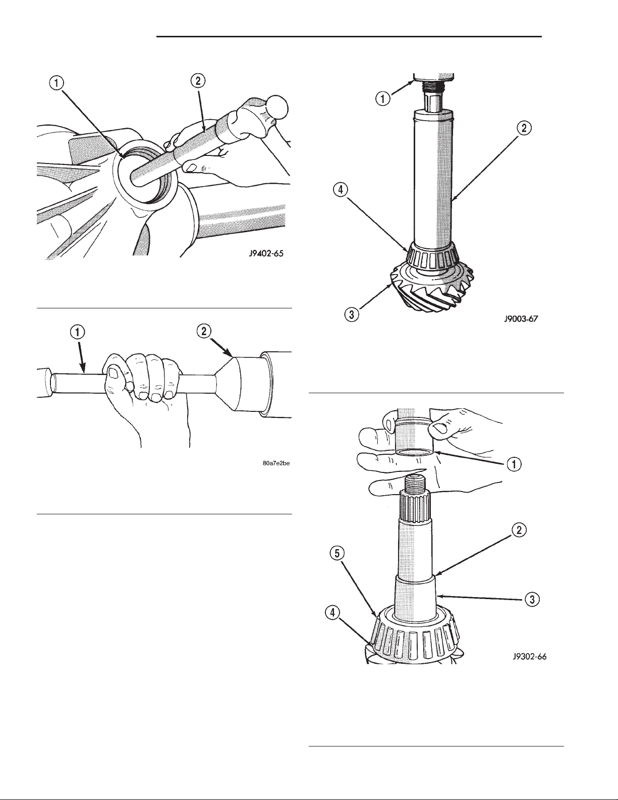
3 - 84 194 RBI AXLE XJ
REMOVAL AND INSTALLATION (Continued)
Fig. 41 Pinion Front Bearing Cup Installation
1 – INSTALLER
2 – HANDLE
Fig. 42 Pinion Seal Installation
1 – SPECIAL TOOL C-4171
2 – SPECIAL TOOL C-3972–A
(8) Install the rear bearing and slinger, if
equipped, on the pinion gear with Installer W-262
(Fig. 43).
(9) Install a new collapsible preload spacer on pinion shaft and install pinion gear in housing (Fig. 44).
(10) Install pinion gear in housing.
(11) Install yoke with Installer Screw 8112, Cup
8109, and holder 6958 (Fig. 45).
(12) Install the yoke washer and a new nut on the
pinion gear and tighten the pinion nut until there is
zero bearing end-play.
(13) Tighten the nut to 271 N·m (200 ft. lbs.).
CAUTION: Never loosen pinion gear nut to
decrease pinion gear bearing rotating torque and
never exceed specified preload torque. If preload
torque or rotating torque is exceeded a new collapsible spacer must be installed. The torque
sequence will then have to be repeated.
Fig. 43 Shaft Rear Bearing Installation
1 – PRESS
2 – INSTALLATION TOOL
3 – DRIVE PINION GEAR
4 – DRIVE PINION GEAR SHAFT REAR BEARING
Fig. 44 Collapsible Preload Spacer
1 – COLLAPSIBLE SPACER
2 – SHOULDER
3 – PINION GEAR
4 – OIL SLINGER
5 – REAR BEARING
Page 85
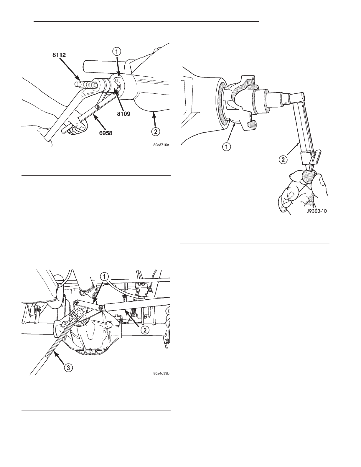
XJ 194 RBI AXLE 3 - 85
REMOVAL AND INSTALLATION (Continued)
• Original Bearings—1to2N·m(10to20in.
lbs.).
• New Bearings — 1.5 to 4 N·m (15 to 35 in. lbs.).
Fig. 45 Pinion Yoke Installation
1 – PINION YOKE
2 – AXLE HOUSING
(14) Using yoke holder 6958 and a torque wrench
set at 474 N·m (350 ft. lbs.), crush collapsible spacer
until bearing end play is taken up (Fig. 46).
NOTE: If the spacer requires more than 474 N·m
(350 ft. lbs.) torque to crush, the collapsible spacer
is defective and must be replaced.
(15) Slowly tighten the nut in 6.8 N·m (5 ft. lbs.)
increments until the rotating torque is achieved.
Measure the rotating torque frequently to avoid over
crushing the collapsible spacer (Fig. 47).
Fig. 46 Tightening Pinion Nut–Typical
1 – SPECIAL TOOL 6958
2 – 1 in. PIPE
3 – 3/4 DRIVE TORQUE WRENCH
Fig. 47 Check Pinion Gear Rotating Torque
1 – PINION YOKE
2 – INCH POUND TORQUE WRENCH
(17) Install differential in housing.
FINAL ASSEMBLY
(1) Scrape the residual sealant from the housing
and cover mating surfaces. Clean the mating surfaces
with mineral spirits. Apply a bead of Mopart Silicone
Rubber Sealant, or equivalent, on the housing cover
(Fig. 48).
Install the housing cover within 5 minutes
after applying the sealant.
(2) Install the cover on the differential with the
attaching bolts. Install the identification tag. Tighten
the cover bolts to 41 N·m (30 ft. lbs.) torque.
CAUTION: Overfilling the differential can result in
lubricant foaming and overheating.
(3) Refill the differential housing with gear lubricant. Refer to the Lubricant Specifications section of
this group for the gear lubricant requirements.
(4) Install the fill hole plug.
(16) Check bearing rotating torque with a (in. lbs.)
torque wrench (Fig. 47). The torque necessary to
rotate the pinion gear should be:
Page 86
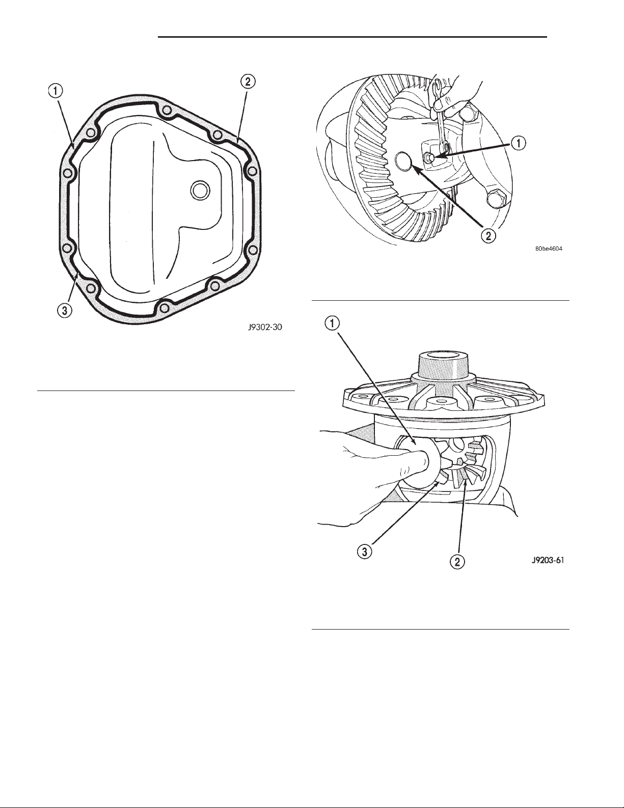
3 - 86 194 RBI AXLE XJ
REMOVAL AND INSTALLATION (Continued)
Fig. 49 Pinion Mate Shaft Lock Screw
1 – LOCK SCREW
2 – PINION MATE SHAFT
Fig. 48 Typical Housing Cover With Sealant
1 – SEALING SURFACE
2 – CONTOUR OF BEAD
3 – BEAD THICKNESS 6.35mm (1/4”)
DISASSEMBLY AND ASSEMBLY
STANDARD DIFFERENTIAL
DISASSEMBLY
(1) Remove pinion mate shaft lock screw (Fig. 49).
(2) Remove pinion mate shaft.
(3) Rotate the differential side gears and remove
the differential pinion gears and thrust washers (Fig.
50).
(4) Remove the differential side gears and thrust
washers.
ASSEMBLY
(1) Install the differential side gears and thrust
washers.
(2) Install the differential pinion gears and thrust
washers.
(3) Install the pinion mate shaft.
(4) Align the hole in the pinion mate shaft with
the hole in the differential case and install the pinion
mate shaft lock screw.
(5) Lubricate all differential components with
hypoid gear lubricant.
Fig. 50 Pinion Mate Gear Removal
1 – THRUST WASHER
2 – SIDE GEAR
3 – PINION MATE GEAR
Page 87
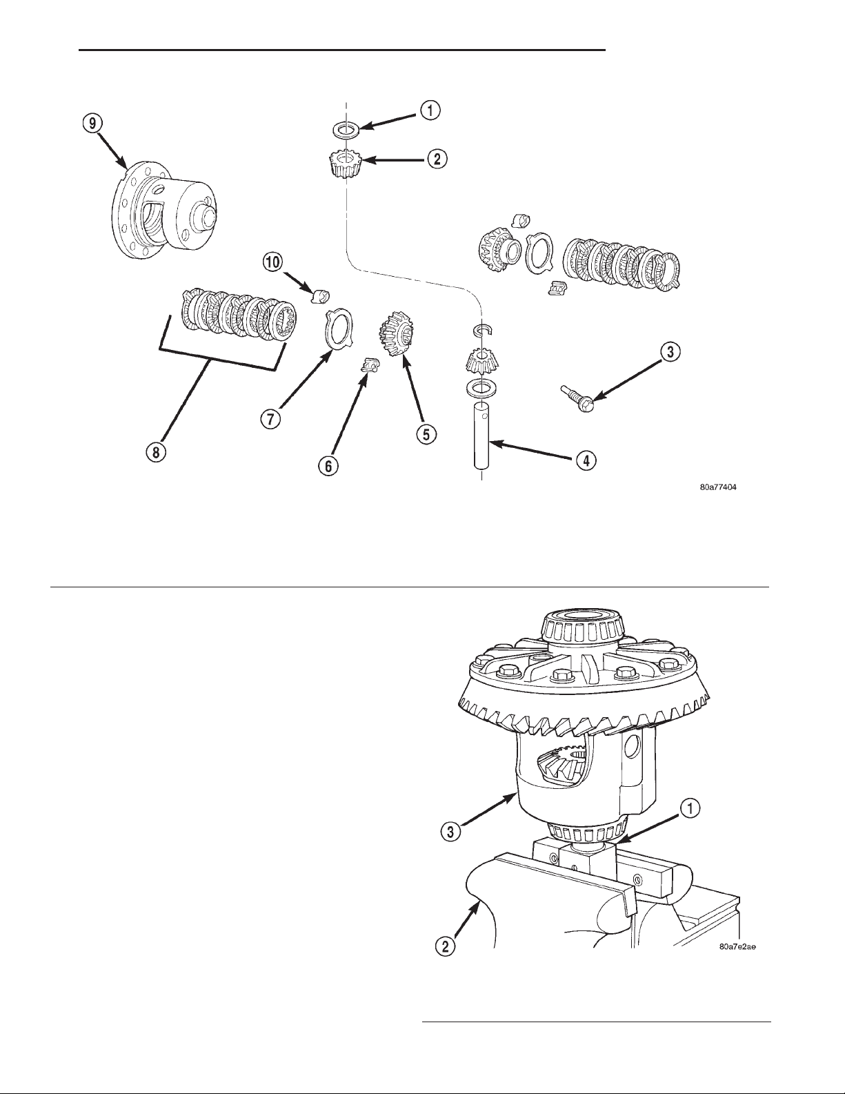
XJ 194 RBI AXLE 3 - 87
DISASSEMBLY AND ASSEMBLY (Continued)
Fig. 51 Trac–lokYDifferential Components
1 – THRUST WASHER
2 – PINION
3 – SHAFT LOCK SCREW
4 – PINION MATE SHAFT
5 – SIDE GEAR
TRAC-LOKY DIFFERENTIAL
The Trac–loky differential components are illustrated in (Fig. 51). Refer to this illustration during
repair service.
DISASSEMBLY
(1) Clamp Side Gear Holding Tool 6965 in a vise.
(2) Position the differential case on Side Gear
Holding Tool 6965 (Fig. 52).
(3) Remove ring gear, if necessary. Ring gear
removal is necessary only if the ring gear is to be
replaced. The Trac-loky differential can be serviced
with the ring gear installed.
(4) Remove the pinion gear mate shaft lock screw
(Fig. 53).
(5) Remove the pinion gear mate shaft. If necessary, use a drift and hammer (Fig. 54).
(6) Install and lubricate Step Plate C-6960-3 (Fig.
55).
6 – RETAINER
7 – DISC
8 – CLUTCH PACK
9 – DIFFERENTIAL CASE
10 – RETAINER
Fig. 52 Differential Case Holding Tool
1 – SPECIAL TOOL 6965
2 – VISE
3 – DIFFERENTIAL
Page 88
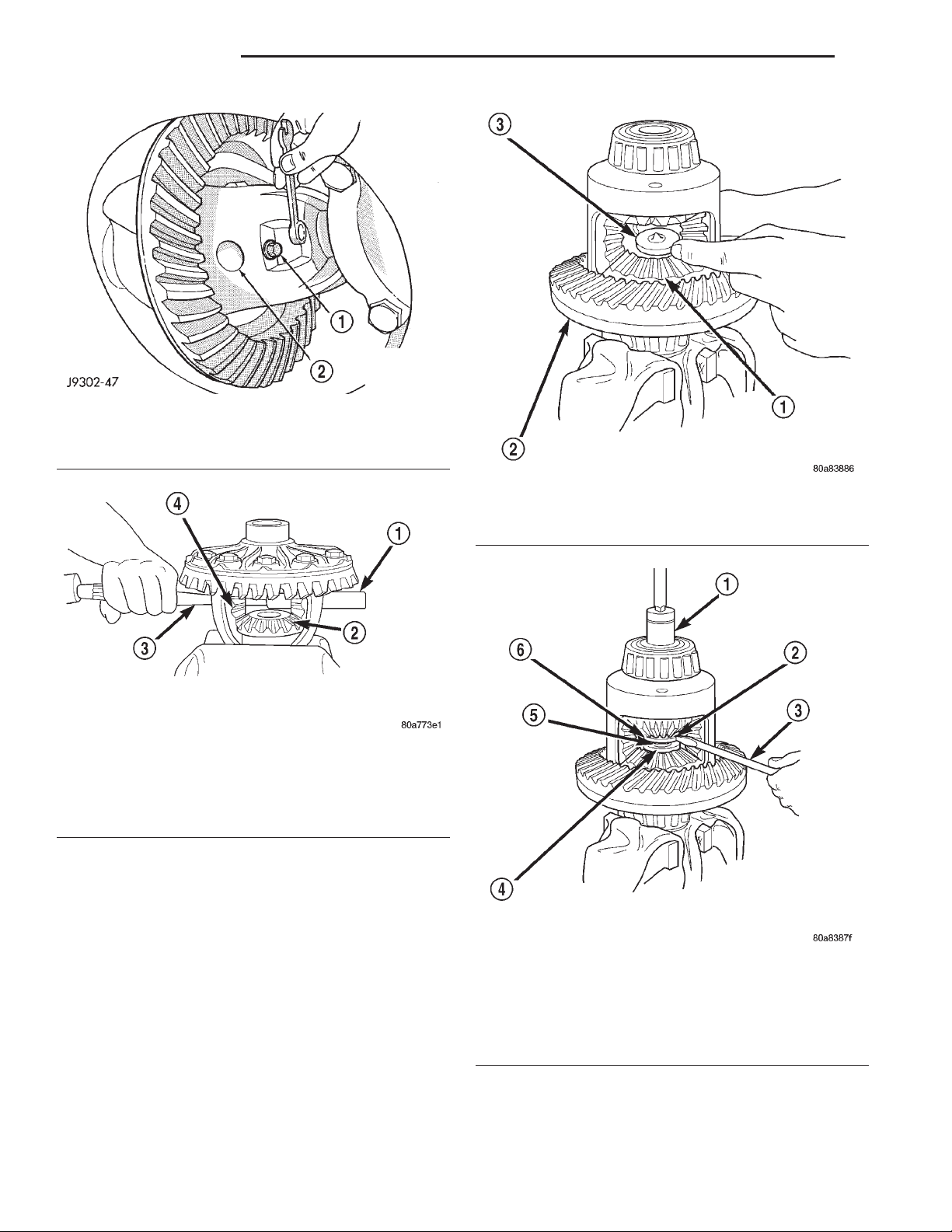
3 - 88 194 RBI AXLE XJ
DISASSEMBLY AND ASSEMBLY (Continued)
Fig. 53 Mate Shaft Lock Screw
1 – LOCK SCREW
2 – PINION GEAR MATE SHAFT
Fig. 55 Step Plate Tool Installation
1 – LOWER SIDE GEAR
2 – DIFFERENTIAL CASE
3 – SPECIAL TOOL C-6960–3
Fig. 54 Mate Shaft Removal
1 – PINION MATE SHAFT
2 – SIDE GEAR
3 – DRIFT
4 – PINION MATE GEAR
(7) Assemble Threaded Adapter C-6960-1 into top
side gear. Thread Forcing Screw C-6960-4 into
adapter until it becomes centered in adapter plate.
(8) Position a small screw driver in slot of
Threaded Adapter C-6960-1 (Fig. 56) to prevent
adapter from turning.
(9) Tighten forcing screw tool 122 N·m (90 ft. lbs.)
maximum to compress Belleville springs in clutch
packs (Fig. 57).
Fig. 56 Threaded Adapter Installation
1 – SOCKET
2 – SLOT IN ADAPTER
3 – SCREWDRIVER
4 – DISC C-6960–3
5 – THREADED ROD C-6960–4
6 – THREADED ADAPTER DISC C–6960–1
Page 89
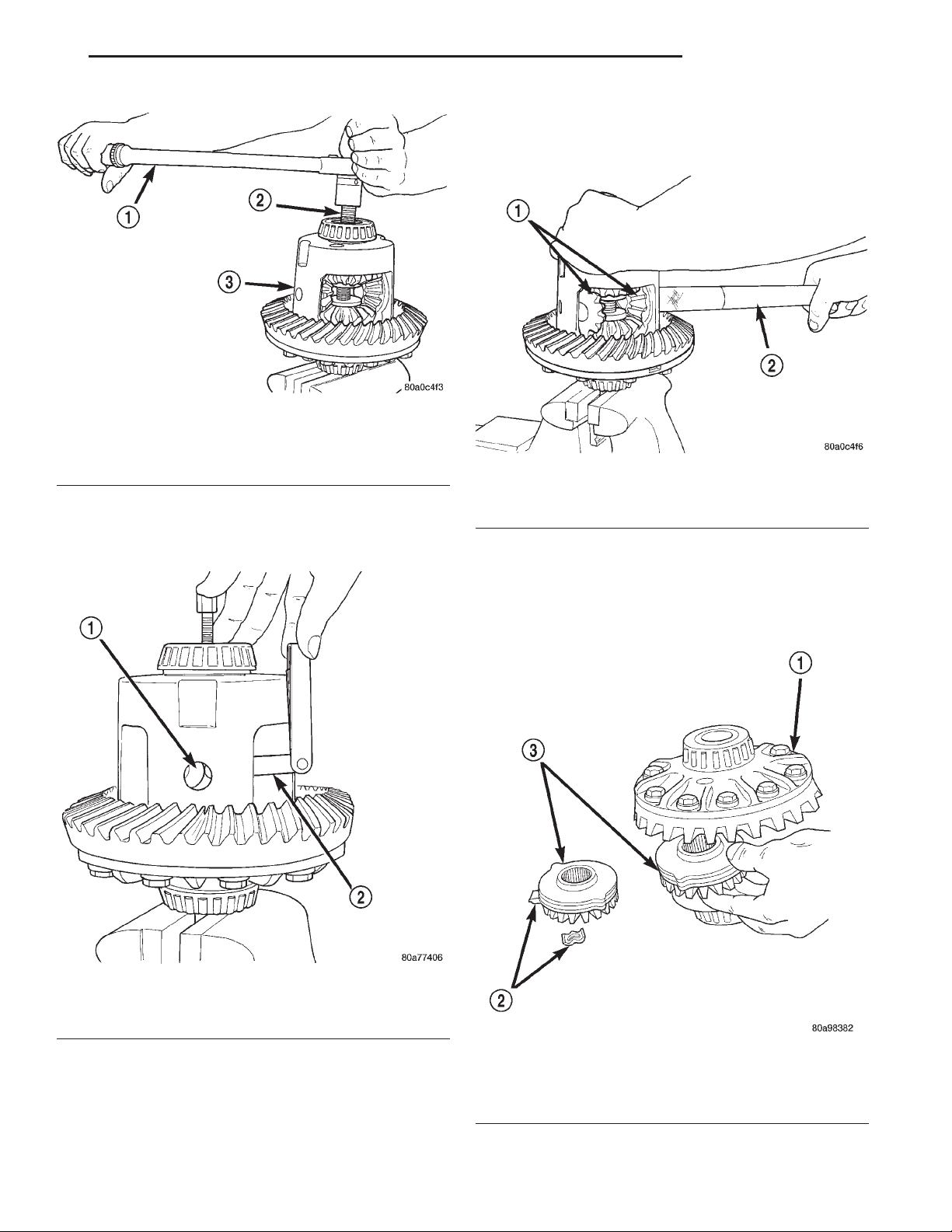
XJ 194 RBI AXLE 3 - 89
DISASSEMBLY AND ASSEMBLY (Continued)
(13) Rotate differential case until the pinion gears
can be removed.
(14) Remove pinion gears from differential case.
Fig. 57 Tighten Belleville Spring Compressor Tool
1 – TORQUE WRENCH
2 – TOOLASSEMBLED
3 – DIFFERENTIAL CASE
(10) Using an appropriate size feeler gauge,
remove thrust washers from behind the pinion gears
(Fig. 58).
1 – PINION GEARS
2–TOOL
(15) Remove Forcing Screw C-6960-4, Step Plate
C-6960-3, and Threaded Adapter C-6960-1.
(16) Remove top side gear, clutch pack retainer,
and clutch pack. Keep plates in correct order during
removal (Fig. 60).
Fig. 59 Pinion Gear Removal
Fig. 58 Remove Pinion Gear Thrust Washer
1 – THRUST WASHER
2 – FEELER GAUGE
(11) Insert Turning Bar C-6960-2 in case (Fig. 59).
(12) Loosen the Forcing Screw C-6960-4 in small
increments until the clutch pack tension is relieved
and the differential case can be turned using Turning
Bar C-6960-2.
Fig. 60 Side Gear & Clutch Disc Removal
1 – DIFFERENTIAL CASE
2 – RETAINER
3 – SIDE GEAR AND CLUTCH DISC PACK
Page 90
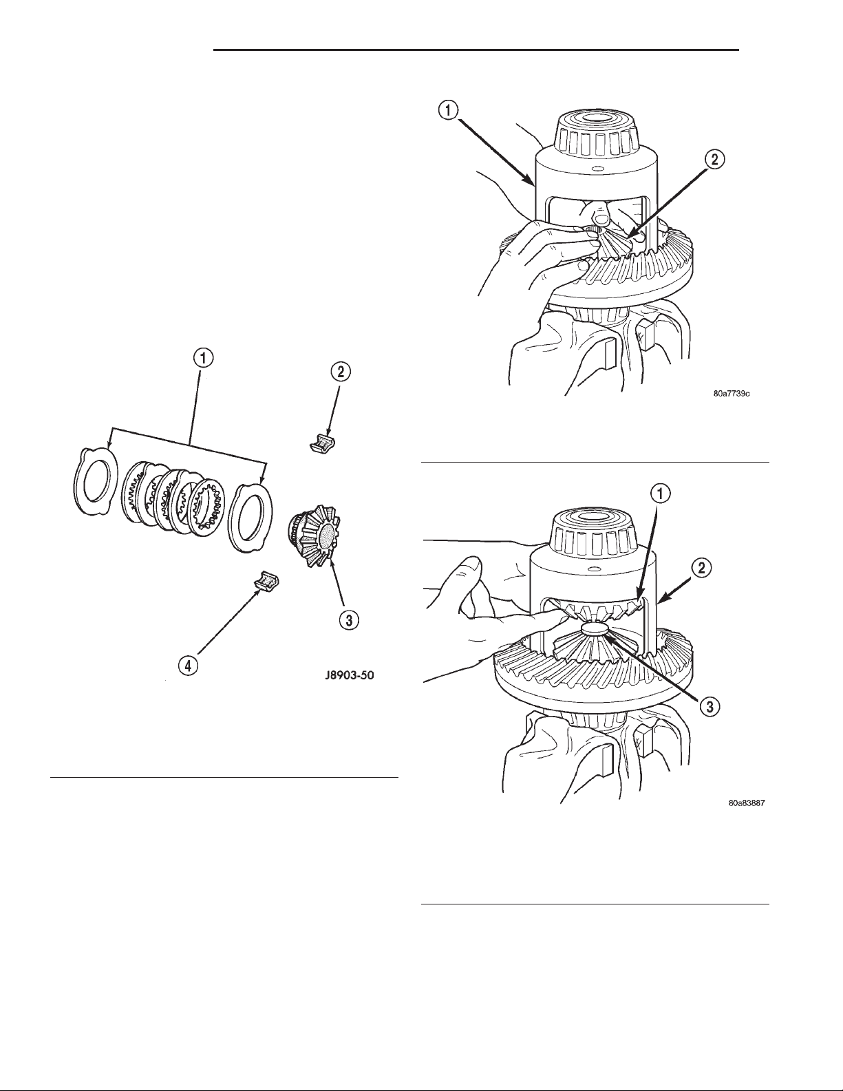
3 - 90 194 RBI AXLE XJ
DISASSEMBLY AND ASSEMBLY (Continued)
(17) Remove differential case from Side Gear Holding Tool 6965. Remove side gear, clutch pack retainer,
and clutch pack. Keep plates in correct order during
removal.
ASSEMBLY
NOTE: The clutch discs are replaceable as complete sets only. If one clutch disc pack is damaged,
both packs must be replaced.
Lubricate each component with gear lubricant
before assembly.
(1) Assemble the clutch discs into packs and
secure disc packs with retaining clips (Fig. 61).
Fig. 62 Clutch Discs & Lower Side Gear Installation
1 – DIFFERENTIAL CASE
2 – LOWER SIDE GEAR AND CLUTCH DISC PACK
Fig. 61 Clutch Disc Pack
1 – CLUTCH PACK
2 – RETAINER
3 – SIDE GEAR
4 – RETAINER
(2) Position assembled clutch disc packs on the
side gear hubs.
(3) Install clutch pack and side gear in the ring
gear side of the differential case (Fig. 62). Be sure
clutch pack retaining clips remain in position
and are seated in the case pockets.
(4) Position the differential case on Side Gear
Holding Tool 6965.
(5) Install lubricated Step Plate C-6960-3 in lower
side gear (Fig. 63).
(6) Install the upper side gear and clutch disc pack
(Fig. 63).
(7) Hold assembly in position. Insert Threaded
Adapter C-6960-1 into top side gear.
Fig. 63 Upper Side Gear & Clutch Disc Pack
Installation
1 – UPPER SIDE GEAR AND CLUTCH DISC PACK
2 – DIFFERENTIAL CASE
3 – SPECIAL TOOL C-6960–3
(8) Insert Forcing Screw C-6960-4.
(9) Tighten forcing screw tool to slightly compress
clutch discs.
(10) Place pinion gears in position in side gears
and verify that the pinion mate shaft hole is aligned.
Page 91
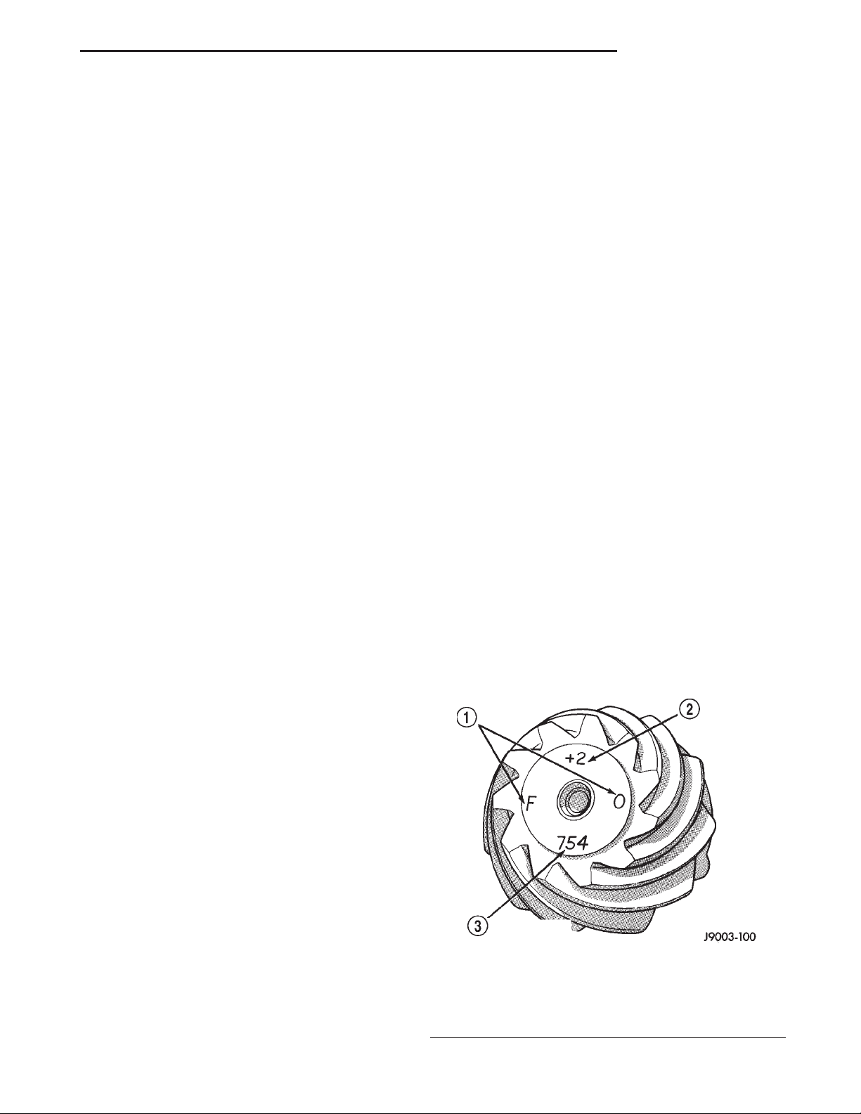
XJ 194 RBI AXLE 3 - 91
DISASSEMBLY AND ASSEMBLY (Continued)
(11) Rotate case with Turning Bar C-6960-2 until
the pinion mate shaft holes in pinion gears align
with holes in case. It may be necessary to slightly
tighten the forcing screw in order to install the pinion gears.
(12) Tighten forcing screw to 122 N·m (90 ft. lbs.)
maximum to compress the Belleville springs.
(13) Lubricate and install thrust washers behind
pinion gears and align washers with a small screw
driver. Insert mate shaft into each pinion gear to verify alignment.
(14) Remove Forcing Screw C-6960-4, Step Plate
C-6960-3, and Threaded Adapter C-6960-1.
(15) Install pinion gear mate shaft and align holes
in shaft and case.
(16) Install the pinion mate shaft lock screw finger
tight to hold shaft during differential installation.
If replacement gears and thrust washers were
installed, it is not necessary to measure the
gear backlash. Correct fit is due to close
machining tolerances during manufacture.
(17) Lubricate all differential components with
hypoid gear lubricant.
CLEANING AND INSPECTION
AXLE COMPONENTS
Wash differential components with cleaning solvent
and dry with compressed air. Do not steam clean
the differential components.
Wash bearings with solvent and towel dry, or dry
with compressed air. DO NOT spin bearings with
compressed air. Cup and bearing must be
replaced as matched sets only.
Clean axle shaft tubes and oil channels in housing.
Inspect for;
• Smooth appearance with no broken/dented surfaces on the bearing rollers or the roller contact surfaces.
• Bearing cups must not be distorted or cracked.
• Machined surfaces should be smooth and with-
out any raised edges.
• Raised metal on shoulders of cup bores should
be removed with a hand stone.
• Wear and damage to pinion gear mate shaft,
pinion gears, side gears and thrust washers. Replace
as a matched set only.
• Ring and pinion gear for worn and chipped
teeth.
• Ring gear for damaged bolt threads. Replaced as
a matched set only.
• Pinion yoke for cracks, worn splines, pitted
areas, and a rough/corroded seal contact surface.
Repair or replace as necessary.
• Preload shims for damage and distortion. Install
new shims, if necessary.
TRAC-LOKY
Clean all components in cleaning solvent. Dry components with compressed air. Inspect clutch pack
plates for wear, scoring or damage. Replace both
clutch packs if any one component in either pack is
damaged. Inspect side gears and pinions. Replace
any gear that is worn, cracked, chipped or damaged.
Inspect differential case and pinion shaft. Replace if
worn or damaged.
PRESOAK PLATES AND DISC
Plates and discs with fiber coating (no grooves or
lines) must be presoaked in Friction Modifier before
assembly. Soak plates and discs for a minimum of 20
minutes.
ADJUSTMENTS
PINION GEAR DEPTH
GENERAL INFORMATION
Ring and pinion gears are supplied as matched
sets only. The identifying numbers for the ring and
pinion gear are etched into the face of each gear (Fig.
64). A plus (+) number, minus (–) number or zero (0)
is etched into the face of the pinion gear. This number is the amount (in thousandths of an inch) the
depth varies from the standard depth setting of a
pinion etched with a (0). The standard setting from
the center line of the ring gear to the back face of the
pinion is 96.850 mm (3.813 in.). The standard depth
provides the best teeth contact pattern. Refer to
Backlash and Contact Pattern Analysis Paragraph in
this section for additional information.
Fig. 64 Pinion Gear ID Numbers
1 – PRODUCTION NUMBERS
2 – DRIVE PINION GEAR DEPTH VARIANCE
3 – GEAR MATCHING NUMBER (SAME AS RING GEAR
NUMBER)
Page 92
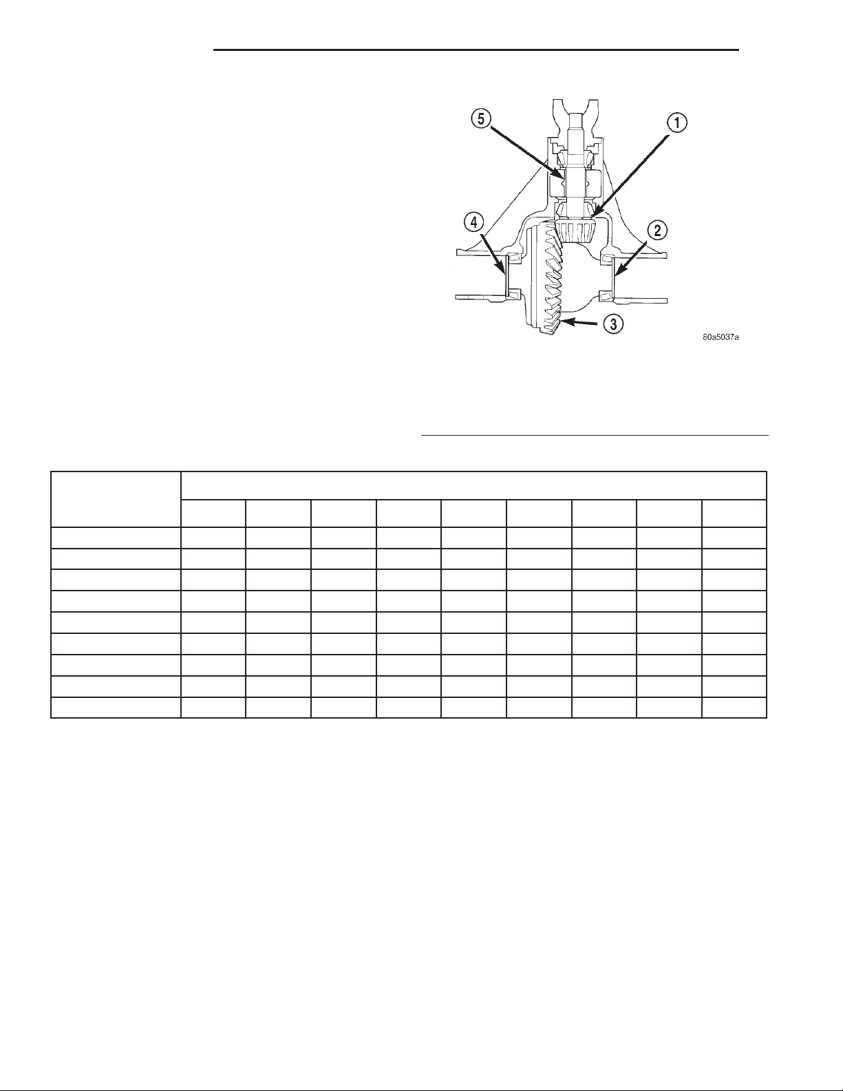
3 - 92 194 RBI AXLE XJ
ADJUSTMENTS (Continued)
Compensation for pinion depth variance is
achieved with select shims. The shims are placed
under the inner pinion bearing cone (Fig. 65).
If a new gear set is being installed, note the depth
variance etched into both the original and replacement pinion gear. Add or subtract the thickness of
the original depth shims to compensate for the difference in the depth variances. Refer to the Depth Variance charts.
Note where Old and New Pinion Marking columns
intersect. Intersecting figure represents plus or
minus amount needed.
Note the etched number on the face of the drive
pinion gear (–1, –2, 0, +1, +2, etc.). The numbers represent thousands of an inch deviation from the standard. If the number is negative, add that value to the
required thickness of the depth shim(s). If the number is positive, subtract that value from the thickness
of the depth shim(s). If the number is 0 no change is
necessary. Refer to the Pinion Gear Depth Variance
Chart.
PINION GEAR DEPTH VARIANCE
1 – PINION GEAR DEPTH SHIM
2 – DIFFERENTIAL BEARING SHIM-PINION GEAR SIDE
3 – RING GEAR
4 – DIFFERENTIAL BEARING SHIM-RING GEAR SIDE
5 – COLLAPSIBLE SPACER
Fig. 65 Shim Locations
Original Pinion
Replacement Pinion Gear Depth Variance
Gear Depth
Variance
−4 −3 −2 −1 0 +1 +2 +3 +4
+4 +0.008 +0.007 +0.006 +0.005 +0.004 +0.003 +0.002 +0.001 0
+3 +0.007 +0.006 +0.005 +0.004 +0.003 +0.002 +0.001 0 −0.001
+2 +0.006 +0.005 +0.004 +0.003 +0.002 +0.001 0 −0.001 −0.002
+1 +0.005 +0.004 +0.003 +0.002 +0.001 0 −0.001 −0.002 −0.003
0 +0.004 +0.003 +0.002 +0.001 0 −0.001 −0.002 −0.003 −0.004
−1 +0.003 +0.002 +0.001 0 −0.001 −0.002 −0.003 −0.004 −0.005
−2 +0.002 +0.001 0 −0.001 −0.002 −0.003 −0.004 −0.005 −0.006
−3 +0.001 0 −0.001 −0.002 −0.003 −0.004 −0.005 −0.006 −0.007
−4 0 −0.001 −0.002 −0.003 −0.004 −0.005 −0.006 −0.007 −0.008
PINION DEPTH MEASUREMENT AND ADJUSTMENT
Measurements are taken with pinion cups and pinion bearings installed in housing. Take measurements with a Pinion Gauge Set, Pinion Block 6735,
Arbor Discs 6732, and Dial Indicator C-3339 (Fig.
66).
(1) Assemble Pinion Height Block 6739, Pinion
Block 6735, and rear pinion bearing onto Screw 6741
(Fig. 66).
(2) Insert assembled height gauge components,
rear bearing and screw into axle housing through
pinion bearing cups (Fig. 67).
(3) Install front pinion bearing and Cone 6740
hand tight (Fig. 66).
(4) Place Arbor Disc 6732 on Arbor D-115-3 in position in axle housing side bearing cradles (Fig. 68).
Install differential bearing caps on Arbor Discs and
tighten cap bolts. Refer to the Torque Specifications
in this section.
NOTE: Arbor Discs 6732 have different step diameters to fit other axle sizes. Pick correct size step for
axle being serviced.
(5) Assemble Dial Indicator C-3339 into Scooter
Block D-115-2 and secure set screw.
Page 93
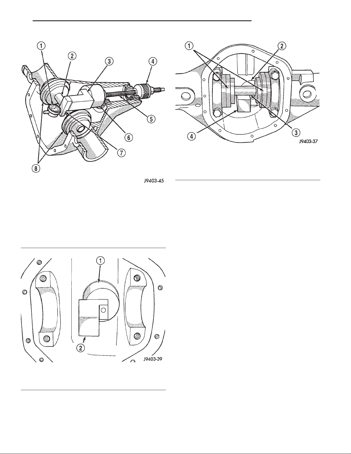
XJ 194 RBI AXLE 3 - 93
ADJUSTMENTS (Continued)
Fig. 68 Gauge Tools In Housing—Typical
1 – ARBOR DISC
2 – PINION BLOCK
3 – ARBOR
4 – PINION HEIGHT BLOCK
Fig. 66 Pinion Gear Depth Gauge Tools—Typical
1 – DIAL INDICATOR
2 – ARBOR
3 – PINION HEIGHT BLOCK
4 – CONE
5 – SCREW
6 – PINION BLOCK
7 – SCOOTER BLOCK
8 – ARBOR DISC
Fig. 67 Pinion Height Block—Typical
1 – PINION BLOCK
2 – PINION HEIGHT BLOCK
(6) Place Scooter Block/Dial Indicator in position
in axle housing so dial probe and scooter block are
flush against the surface of the pinion height block.
Hold scooter block in place and zero the dial indicator face to the pointer. Tighten dial indicator face
lock screw.
(7) With scooter block still in position against the
pinion height block, slowly slide the dial indicator
probe over the edge of the pinion height block.
Observe how many revolutions counterclockwise the
dial pointer travels (approximately 0.125 in.) to the
out-stop of the dial indicator.
(8) Slide the dial indicator probe across the gap
between the pinion height block and the arbor bar
with the scooter block against the pinion height block
(Fig. 69). When the dial probe contacts the arbor bar,
the dial pointer will turn clockwise. Bring dial
pointer back to zero against the arbor bar, do not
turn dial face. Continue moving the dial probe to the
crest of the arbor bar and record the highest reading.
If the dial indicator can not achieve the zero reading,
the rear bearing cup or the pinion depth gauge set is
not installed correctly.
(9) Select a shim equal to the dial indicator reading plus the drive pinion gear depth variance number
etched in the face of the pinion gear (Fig. 64) using
the opposite sign on the variance number. For example, if the depth variance is –2, add +0.002 in. to the
dial indicator reading.
(10) Remove the pinion depth gauge components
from the axle housing
Page 94
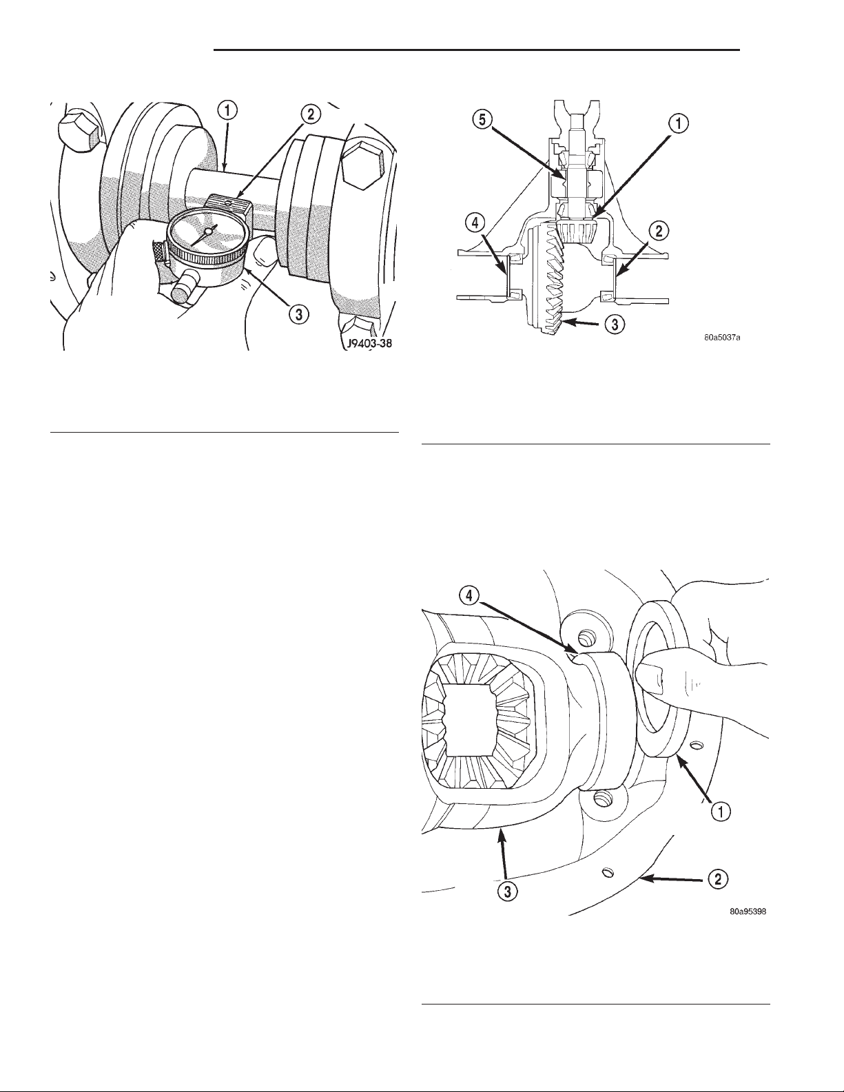
3 - 94 194 RBI AXLE XJ
ADJUSTMENTS (Continued)
Fig. 70 Axle Adjustment Shim Locations
Fig. 69 Pinion Gear Depth Measurement—Typical
1 – ARBOR
2 – SCOOTER BLOCK
3 – DIAL INDICATOR
1 – PINION GEAR DEPTH SHIM
2 – DIFFERENTIAL BEARING SHIM-PINION GEAR SIDE
3 – RING GEAR
4 – DIFFERENTIAL BEARING SHIM-RING GEAR SIDE
5 – COLLAPSIBLE SPACER
DIFFERENTIAL BEARING PRELOAD AND GEAR BACKLASH
Differential side bearing preload and gear backlash
is achieved by selective shims inserted between the
bearing cup and the axle housing. The proper shim
thickness can be determined using slip-fit dummy
bearings D-348 in place of the differential side bearings and a dial indicator C-3339. Before proceeding
with the differential bearing preload and gear backlash measurements, measure the pinion gear depth
and prepare the pinion gear for installation. Establishing proper pinion gear depth is essential to establishing gear backlash and tooth contact patterns.
After the overall shim thickness to take up differential side play is measured, the pinion gear is
installed, and the gear backlash shim thickness is
measured. The overall shim thickness is the total of
the dial indicator reading, starting point shim thickness, and the preload specification added together.
The gear backlash measurement determines the
thickness of the shim used on the ring gear side of
the differential case. Subtract the gear backlash shim
thickness from the total overall shim thickness and
select that amount for the pinion gear side of the differential (Fig. 70).
(3) Install dummy side bearings D-348 on differen-
tial case.
(4) Install differential case in axle housing.
(5) Insert Dummy Shims 8107 (0.118 in. (3.0 mm))
starting point shims between the dummy bearing
and the axle housing (Fig. 71).
SHIM SELECTION
NOTE: It is difficult to salvage the differential side
bearings during the removal procedure. Install
replacement bearings if necessary.
(1) Remove side bearings from differential case.
(2) Install ring gear, if necessary, on differential
case and tighten bolts to specification.
Fig. 71 Insert Starting Point Shims
1 – SPECIAL TOOL 8107
2 – AXLE HOUSING
3 – DIFFERENTIAL CASE
4 – SPECIAL TOOL D-348
Page 95
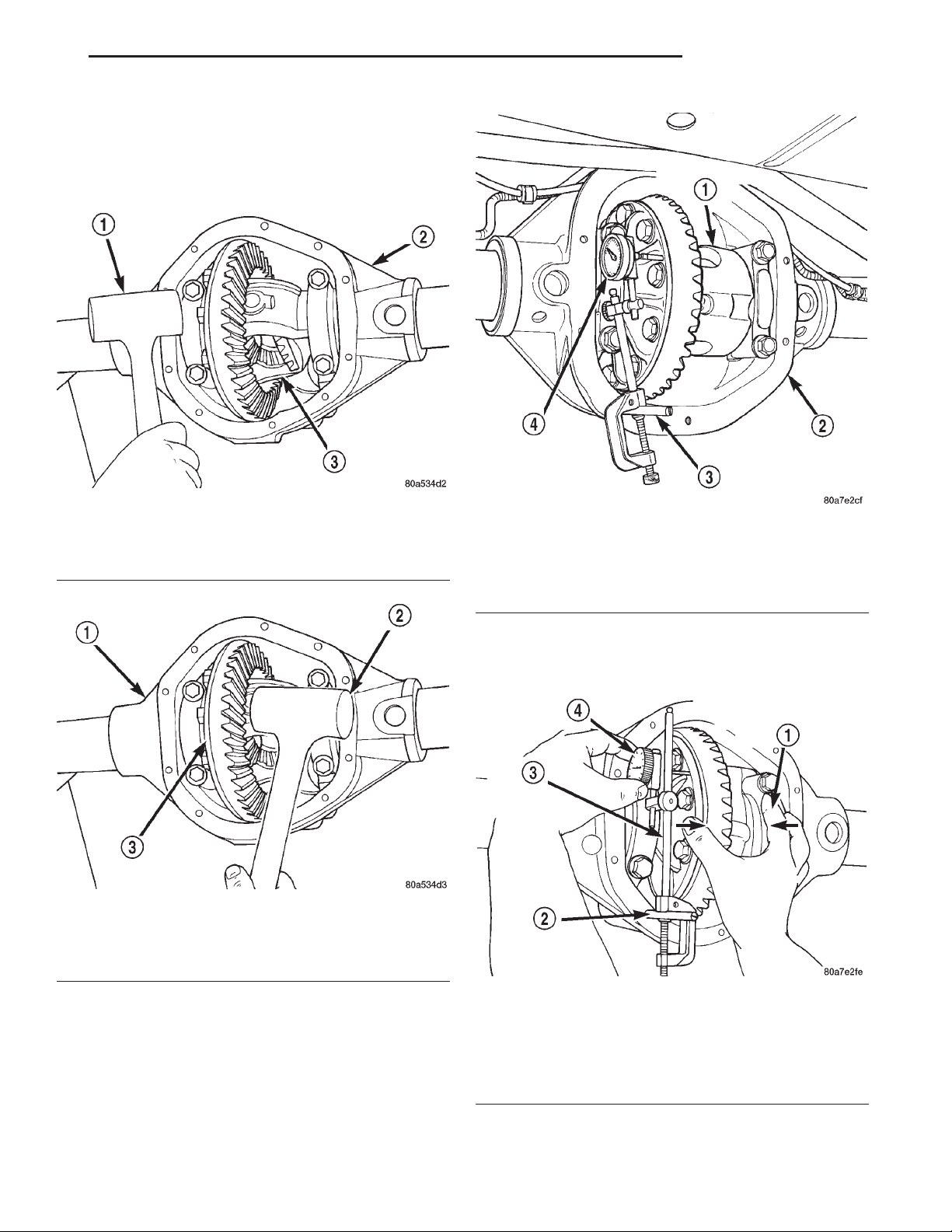
XJ 194 RBI AXLE 3 - 95
ADJUSTMENTS (Continued)
(6) Install the marked bearing caps in their correct
positions. Install and snug the bolts.
(7) Using a dead-blow type mallet, seat the differential dummy bearings to each side of the axle housing (Fig. 72) and (Fig. 73).
Fig. 72 Seat Pinion Gear Dummy Side Bearing
1 – MALLET
2 – AXLE HOUSING
3 – DIFFERENTIAL CASE
Fig. 73 Seat Ring Gear Side Dummy Bearing
1 – AXLE HOUSING
2 – MALLET
3 – DIFFERENTIAL CASE
Fig. 74 Differential Side play Measurement
1 – DIFFERENTIAL CASE
2 – AXLE HOUSING
3 – SPECIAL TOOL C-3288–B
4 – SPECIAL TOOL C-3339
(12) Push firmly and hold differential case to ring
gear side of the axle housing (Fig. 76).
(13) Record dial indicator reading.
(8) Thread guide stud C-3288-B into rear cover
bolt hole below ring gear (Fig. 74).
(9) Attach dial indicator C-3339 to guide stud.
Position the dial indicator plunger on a flat surface
on a ring gear bolt head (Fig. 74).
(10) Push firmly and hold differential case to pinion gear side of axle housing (Fig. 75).
(11) Zero dial indicator face to pointer.
Fig. 75 Hold Differential Case and Zero Dial
Indicator
1 – FORCE DIFFERENTIAL CASE TO PINION GEAR SIDE
2 – SPECIAL TOOL C-3288–B
3 – SPECIAL TOOL C-3339
4 – ZERO DIAL INDICATOR FACE
Page 96
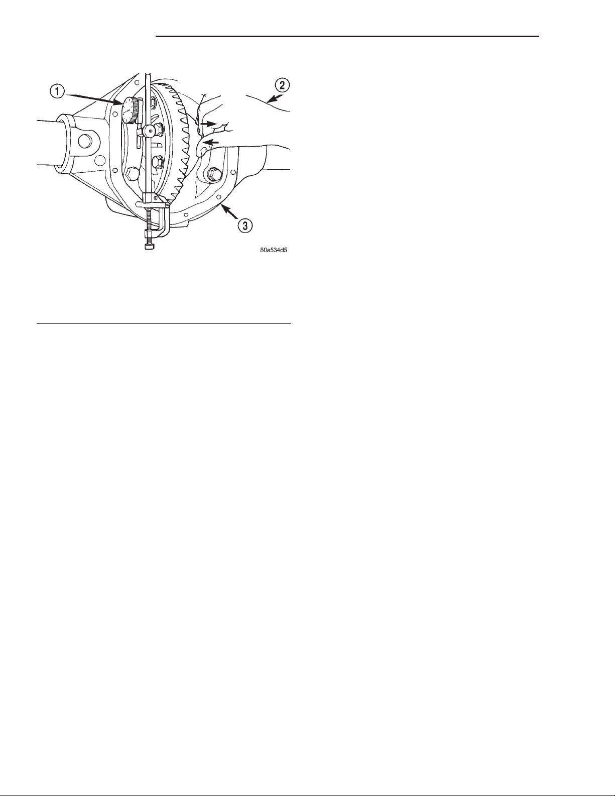
3 - 96 194 RBI AXLE XJ
ADJUSTMENTS (Continued)
(22) Zero dial indicator face to pointer.
(23) Push and hold differential case to ring gear
side of the axle housing.
(24) Record dial indicator reading.
(25) Subtract 0.002 in. (0.05 mm) from the dial
indicator reading to compensate for backlash between
ring and pinion gears. This total is the thickness of
shim required to achieve proper backlash.
(26) Subtract the backlash shim thickness from
the total preload shim thickness. The remainder is
the shim thickness required on the pinion side of the
axle housing.
(27) Rotate dial indicator out of the way on guide
stud.
(28) Remove differential case and dummy bearings
from axle housing.
Fig. 76 Hold Differential Case and Read Dial
Indicator
1 – READ DIAL INDICATOR
2 – FORCE DIFFERENTIAL CASE TO RING GEAR SIDE
3 – AXLE HOUSING
(14) Add the dial indicator reading to the starting
point shim thickness to determine total shim thickness to achieve zero differential end play.
(15) Add 0.008 in. (0.2 mm) to the zero end play
total. This new total represents the thickness of
shims to compress, or preload the new bearings when
the differential is installed.
(16) Rotate dial indicator out of the way on guide
stud.
(17) Remove differential case, dummy bearings,
and starting point shims from axle housing.
(18) Install pinion gear in axle housing. Install the
yoke and establish the correct pinion rotating torque.
(19) Install differential case and dummy bearings
in axle housing (without shims) and tighten retaining
cap bolts.
(20) Position the dial indicator plunger on a flat
surface between the ring gear bolt heads (Fig. 74).
(21) Push and hold differential case toward pinion
gear.
(29) Install new side bearing cones and cups on
differential case.
(30) Install spreader W-129-B, utilizing some components of Adapter Set 6987, on axle housing and
spread axle opening enough to receive differential
case.
(31) Place side bearing shims in axle housing
against axle tubes.
(32) Install differential case in axle housing.
(33) Rotate the differential case several times to
seat the side bearings.
(34) Position the indicator plunger against a ring
gear tooth (Fig. 77).
(35) Push and hold ring gear upward while not
allowing the pinion gear to rotate.
(36) Zero dial indicator face to pointer.
(37) Push and hold ring gear downward while not
allowing the pinion gear to rotate. Dial indicator
reading should be between 0.12 mm (0.005 in.) and
0.20 mm (0.008 in.). If backlash is not within specifications transfer the necessary amount of shim thickness from one side of the differential housing to the
other (Fig. 78).
Page 97
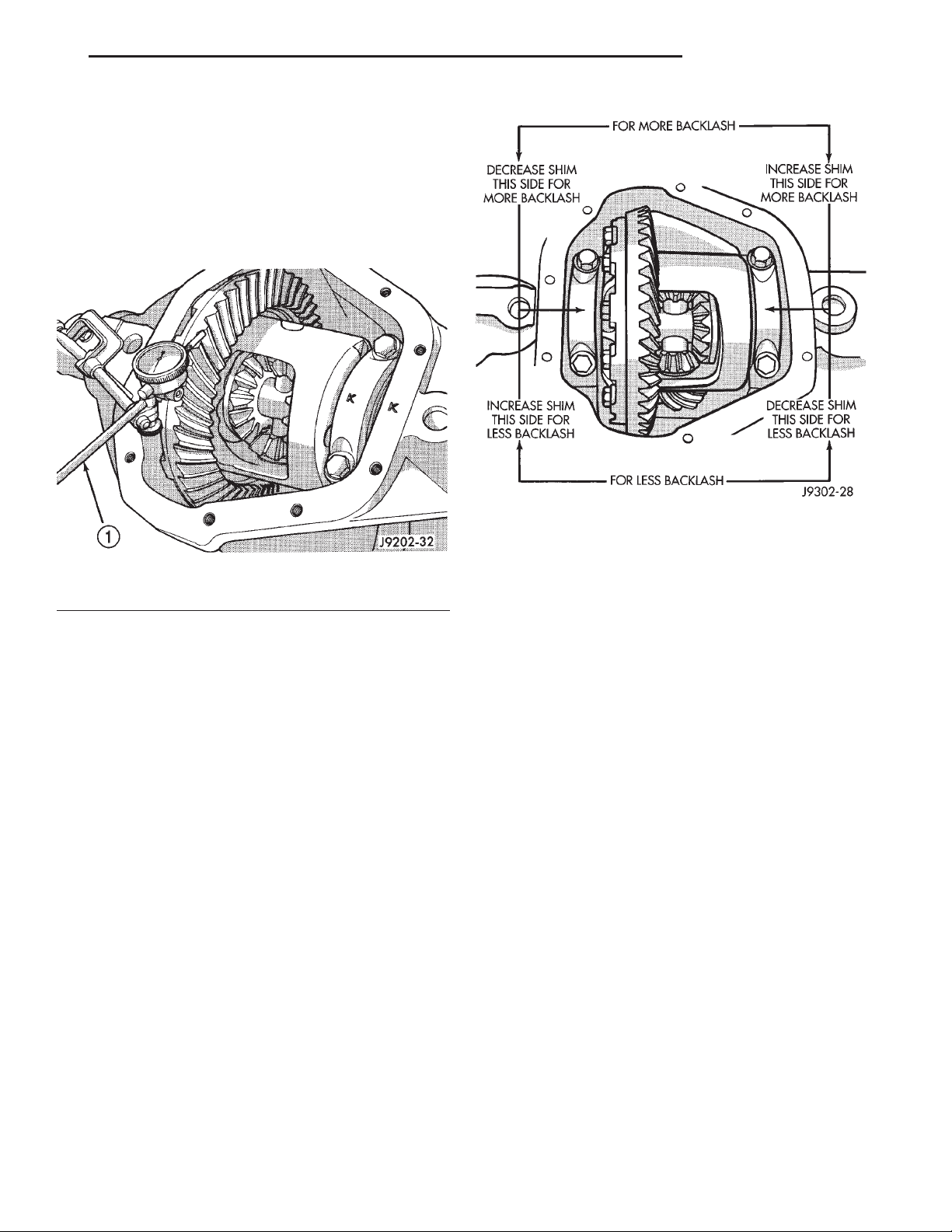
XJ 194 RBI AXLE 3 - 97
ADJUSTMENTS (Continued)
(38) Verify differential case and ring gear runout
by measuring ring to pinion gear backlash at eight
locations around the ring gear. Readings should not
vary more than 0.05 mm (0.002 in.). If readings vary
more than specified, the ring gear or the differential
case is defective.
After the proper backlash is achieved, perform the
Gear Contact Pattern Analysis procedure.
Fig. 77 Ring Gear Backlash Measurement
1 – DIAL INDICATOR
GEAR CONTACT PATTERN ANALYSIS
The ring gear and pinion teeth contact patterns
will show if the pinion depth is correct in the axle
housing. It will also show if the ring gear backlash
has been adjusted correctly. The backlash can be
adjusted within specifications to achieve desired
tooth contact patterns.
(1) Apply a thin coat of hydrated ferric oxide, or
equivalent, to the drive and coast side of the ring
gear teeth.
Fig. 78 Backlash Shim Adjustment
(2) Wrap, twist, and hold a shop towel around the
pinion yoke to increase the turning resistance of the
pinion. This will provide a more distinct contact pattern.
(3) Using a boxed end wrench on a ring gear bolt,
Rotate the differential case one complete revolution
in both directions while a load is being applied from
shop towel.
The areas on the ring gear teeth with the greatest
degree of contact against the pinion teeth will squeegee the compound to the areas with the least amount
of contact. Note and compare patterns on the ring
gear teeth to Gear Tooth Contact Patterns chart (Fig.
79) and adjust pinion depth and gear backlash as
necessary.
Page 98
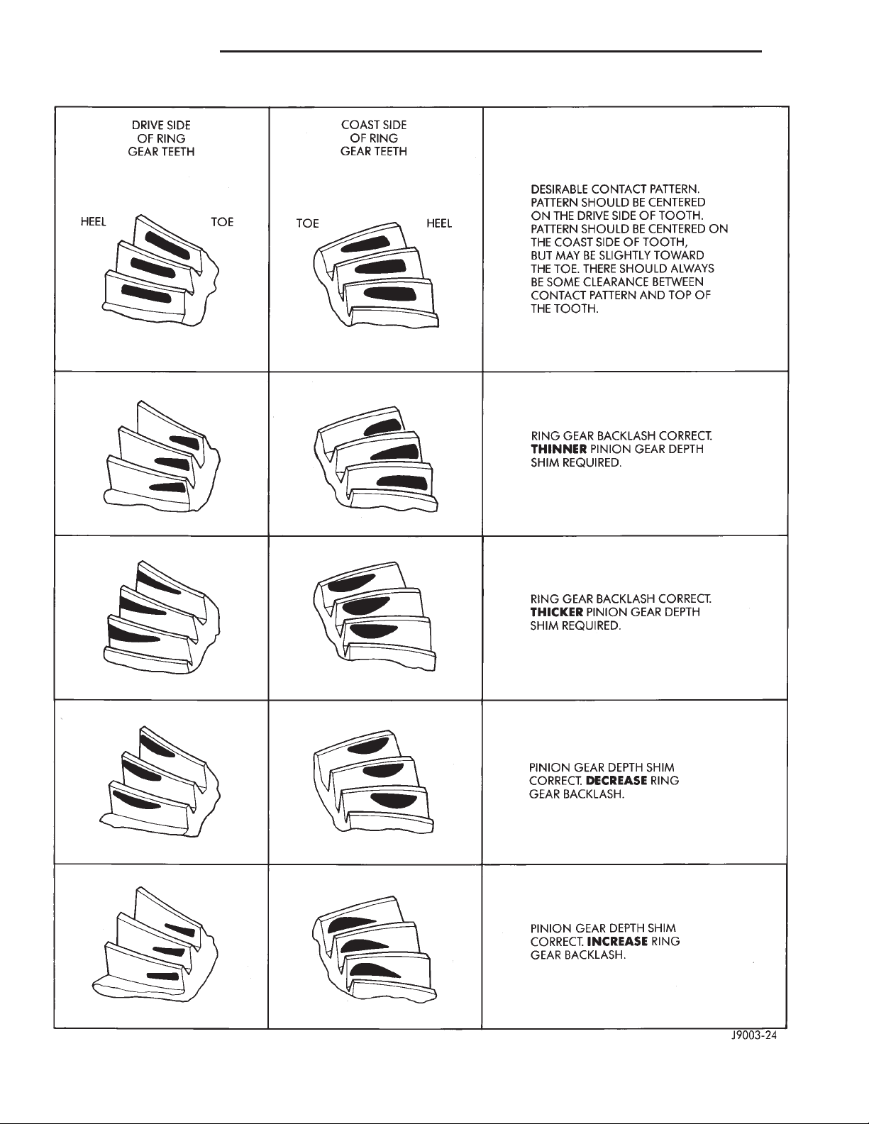
3 - 98 194 RBI AXLE XJ
ADJUSTMENTS (Continued)
Fig. 79 Gear Tooth Contact Patterns
Page 99
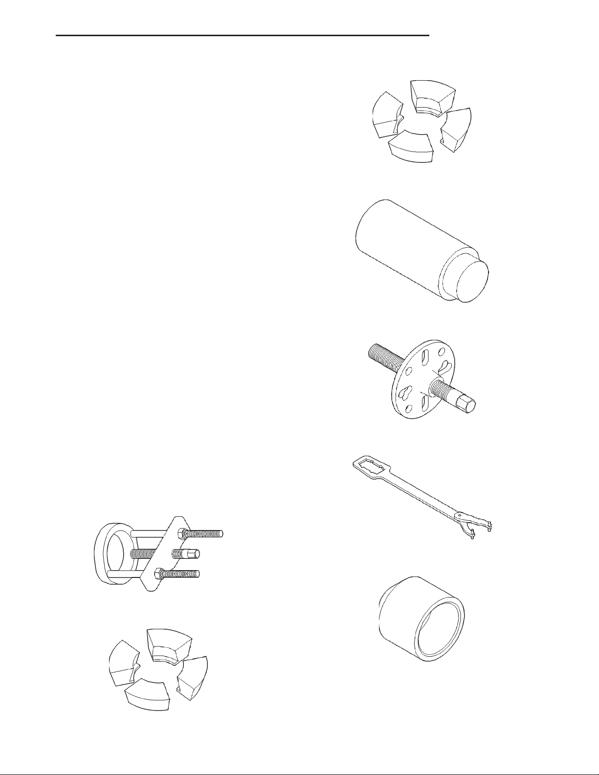
XJ 194 RBI AXLE 3 - 99
SPECIFICATIONS
194 RBI AXLE
DESCRIPTION SPECIFICATION
Axle Type............... Semi–Floating Hypoid
Lubricant ........ SAEThermally Stable 80W–90
Lubricant Trailer Tow ....... Synthetic 75W–140
Lube Capacity ............... 1.66 L (3.50 pts.)
Friction Modifier ............. 0.12 L (3.50 ozs.)
Axle Ratios ................... 3.07, 3.55, 3.73
Differential Bearing Preload . . . 0.1 mm (0.008 in.)
Differential Side Gear Clearance ...... 0–0.15 mm
(0–0.006 in.)
Ring Gear Diameter ......... 19.2 cm (7.562 in.)
Ring Gear Backlash . . 0–0.15 mm (0.005–0.008 in.)
Pinion Std. Depth .......... 96.85 mm (3.813 in.)
Pinion Bearing Preload-Original
Bearings ............ 1–2N·m(10–20 in. lbs.)
Pinion Bearing Preload-New Bearings . . 1.5–4 N·m
(15–35 in. lbs.)
Adapter—C-293-40
Plug—SP-3289
194 RBI AXLE
DESCRIPTION TORQUE
Bolt, Diff. Cover ............ 41N·m(30ft.lbs.)
Bolt, Bearing Cap ........... 77N·m(57ft.lbs.)
Nut, Pinion ....... 271–474 N·m (200–350 ft. lbs.)
Screw, Pinion Mate Shaft Lock ........ 16.25 N·m
(12 ft. lbs.)
Bolt, Ring Gear ...... 95–122 N·m (70–90 ft. lbs.)
Bolt, RWAL/ABS Sensor ....... 8N·m(70in.lbs.)
SPECIAL TOOLS
194 RBI AXLE
Puller—C-293-PA
Puller—C-452
Wrench—C-3281
Adapter—C-293-39
Installer—C-3972-A
Page 100
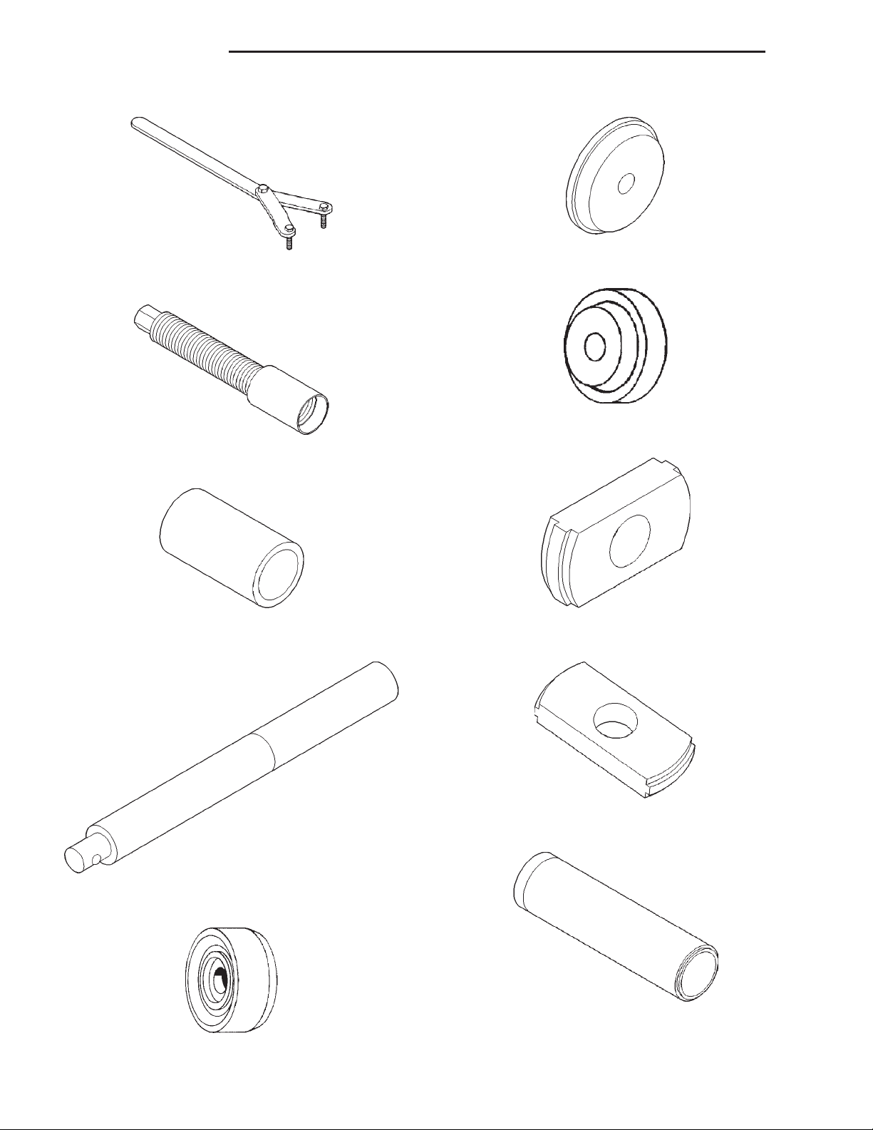
3 - 100 194 RBI AXLE XJ
SPECIAL TOOLS (Continued)
Installer—D-130
Spanner—6958
Installer—D-146
Installer Screw—8112
Cup—8109
Handle—C-4171
Remover—C-4345
Remover—D-149
Installer—W-262
Driver—C-3716-A
 Loading...