

Page 1

XJ EMISSION CONTROL SYSTEM 25 - 1
EMISSION CONTROL SYSTEM
TABLE OF CONTENTS
page page
ON-BOARD DIAGNOSTICS—2.5L DIESEL
ENGINE.................................. 1
ON-BOARD DIAGNOSTICS—2.5L DIESEL ENGINE
TABLE OF CONTENTS
page page
DESCRIPTION AND OPERATION
EMISSION CONTROL SYSTEM—2.5L DIESEL
ENGINE.................................1
DESCRIPTION AND OPERATION
EMISSION CONTROL SYSTEM—2.5L DIESEL
ENGINE
DESCRIPTION
The 2.5L diesel Engine Control Module (ECM) and
Powertrain Control Module (PCM) monitor and control many different circuits in the fuel injection pump
and engine systems. If the ECM senses a problem
with a monitored circuit that indicates an actual
problem, a Diagnostic Trouble Code (DTC) will be
stored in the PCM’s memory, and eventually may
illuminate the Check Engine Lamp constantly while
the key is on. If the problem is repaired, or is intermittent, the ECM will erase the DTC after 40
warm-up cycles without the the fault detected. A
warm-up cycle consists of starting the vehicle when
the engine is cold, then the engine is warmed up to a
certain temperature, and finally, the engine temperature falls to a normal operating temperature, then
the key is turned off.
Certain criteria must be met for a DTC to be
entered into ECM memory. The criteria may be a
specific range of engine rpm, engine or fuel temperature and/or input voltage to the ECM. A DTC indicates that the ECM has identified an abnormal
signal in a circuit or the system. A DTC may indicate
the result of a failure, but never identify the failed
component directly.
EXHAUST EMISSION CONTROLS—2.5L
DIESEL ENGINE........................... 6
DIAGNOSTIC TROUBLE CODES ..............2
There are several operating conditions that the
ECM does not monitor and set a DTC for. Refer to
the following Monitored Circuits and Non–Monitored
Circuits in this section.
ECM MONITORED SYSTEMS
The ECM can detect certain problems in the electrical system.
Open or Shorted Circuit – The ECM will not
distinguish between an open or a short to ground,
however the ECM can determine if the circuit is
shorted to voltage.
Output Device Current Flow – The ECM senses
whether the output devices are electrically connected.
If there is a problem with the circuit, the ECM
senses whether the circuit is open, shorted to ground
(–), or shorted to (+) voltage.
ECM NON–MONITORED SYSTEMS
The ECM does not monitor the following circuits,
systems or conditions that could have malfunctions
that result in driveability problems. A DTC will not
be displayed for these conditions.
Fuel Pressure: Fuel pressure is controlled by the
fuel injection pump. The ECM cannot detect fuel
pressure problems in this component. The ECM does
a comparison analysis of fuel quantity, fuel timing,
fuel temperature, and control sleeve sensor inputs to
determine if a fuel problem exists.
Cylinder Compression: The ECM cannot detect
uneven, low, or high engine cylinder compression.
Page 2
25 - 2 EMISSION CONTROL SYSTEM XJ
DESCRIPTION AND OPERATION (Continued)
Exhaust System: The ECM cannot detect a
plugged, restricted or leaking exhaust system.
Fuel Injector Malfunctions: The ECM cannot
determine if the fuel injector is clogged, or the wrong
injector is installed. The fuel injectors on the diesel
engine are not controlled by the ECM, although a
defective needle movement sensor in the #1 injector
is monitored by the ECM.
Vacuum Assist: Leaks or restrictions in the vac-
uum circuits of the Exhaust Gas Recirculation System (EGR) are not monitored by the ECM.
ECM System Ground: The ECM cannot determine a poor system ground. However, a DTC may be
generated as a result of this condition.
ECM/PCM Connector Engagement: The ECM
cannot determine spread or damaged connector pins.
However, a DTC may be generated as a result of this
condition.
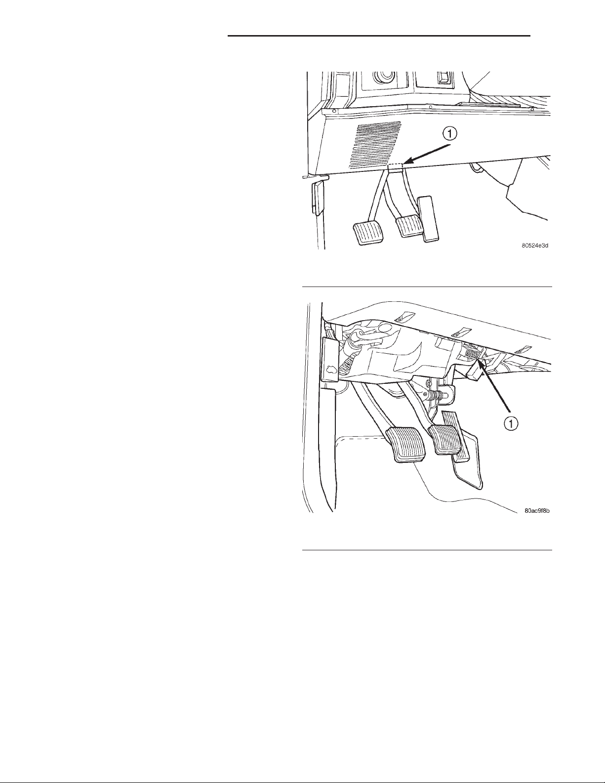
Fig. 1 Data Link Connector Location—LHD
1 – 16–WAY DATA LINK CONNECTOR
HIGH AND LOW LIMITS
The ECM compares input signals from each input
device. It has high and low limits that are programmed into it for that device. If the inputs are not
within specifications and other DTC criteria are met,
a DTC will be stored in memory. Other DTC criteria
might include engine rpm limits or input voltages
from other sensors or switches. The other inputs
might have to be sensed by the ECM when it senses
a high or low input voltage from the control system
device in question.
DIAGNOSTIC TROUBLE CODES
DESCRIPTION
On the following pages, a list of DTC’s is provided
for the 2.5L diesel engine. A DTC indicates that the
ECM has recognized an abnormal signal in a circuit
or the system. A DTC may indicate the result of a
failure, but most likely will not identify the failed
component directly.
ACCESSING DIAGNOSTIC TROUBLE CODES
A stored DTC can be displayed through the use of
the DRB IIIt scan tool. The DRB IIIt connects to the
data link connector. The data link connector is
located under the instrument panel near bottom of
the steering column (Fig. 1) (Fig. 2).
Fig. 2 Data Link Connector Location—RHD
1 – DATA LINK CONNECTOR
ERASING TROUBLE CODES
After the problem has been repaired, use the DRB
IIIt scan tool to erase a DTC.
Page 3

XJ EMISSION CONTROL SYSTEM 25 - 3
DESCRIPTION AND OPERATION (Continued)
MSA CONTROLLER DRBIIIT CODES
Generic Scan Tool Code DRB IIIT Scan Tool Display
P0115 Temperature of Engine Coolant SRC High Exceeded
Temperature of Engine Coolant SRC Low Exceeded
P0180 Fuel Temperature Sensor SRC High Exceeded
Fuel Temperature Sensor SRC Low Exceeded
P0235 Turbocharger Boost Sensor Signal High Exceeded
Turbocharger Boost Sensor Signal Low Exceeded
Turbocharger Boost Sensor Supply High Exceeded
Turbocharger Boost Sensor Supply High Exceeded
Turbocharger Boost Sensor Plausibility
P0400 EGR Open Circuit
EGR Short Circuit
P0500 Veh. Speed Sensor PEC Frequency Too High
Veh. Speed Sensor SRC High Exceeded
Veh. Speed Sensor Plausibility
P0725 Engine Speed Sensor Dyn. Plausibility
Engine Speed Sensor Over Speed Recognition
Engine Speed Sensor Static Plausibilty
P1105 Atmosphere Pressure Sensor SRC High Exceeded
Atmosphere Pressure Sensor SRC Low Exceeded
P1110 Air Temp. Sensor SRC High Exceeded
Air Temp. Sensor SRC Low Exceeded
P1201 Needle Movement Sensor SRC High Exceeded
Needle Movement Sensor SRC Low Exceeded
P1220 Fuel Quantity Actuator Neg Gov Deviation Cold
Fuel Quantity Actuator Neg Gov Deviation Warm
Fuel Quantity Actuator Pos Gov Deviation Cold
Fuel Quantity Actuator Pos Gov Deviation Warm
P1225 Control Sleeve Sensor Signal High Exceeded
Control Sleeve Sensor Start End Pos. Not Attained
Control Sleeve Sensor Stop End Pos. Not Attained
P1230 Timing Governing Negative Governor Deviation
Timing Governing Positive Governor Deviation
P1515 Accel. Pedal Sensor Signal High Exceeded
Accel. Pedal Sensor Supply SRC High Exceeded
Accel. Pedal Sensor Supply SRC Low Exceeded
Accel. Pedal Sensor Plausibility
Page 4

25 - 4 EMISSION CONTROL SYSTEM XJ
DESCRIPTION AND OPERATION (Continued)
Generic Scan Tool Code DRB IIIT Scan Tool Display
P1520 Vehicle Speed Gov Analog Ctrl Control Contact Alone
P1600 Battery Voltage SRC High Exceeded
P1605 Terminal #15 Plausibility After Startup
P1610 Regulator Lower Regulator Limit
Regulator Upper Regulator Limit
P1615 Microcontroller Gate-Array Monitoring
Microcontroller Gate-Array Watchdog
Microcontroller Prepare Fuel Quantity Stop
Microcontroller Recovery Was Occurred
Microcontrller Redundant Overrun Monitoring
P1620 U_REF (2.5V)
P1630 Solenoid Valve Controller Open Circuit
Solenoid Valve Controller Short Circuit
P1635 Glow Relay Controller Open Circuit
Glow Relay Controller Short Circuit
P1660 Redundant Emer. Stop Plausibility In After-Run
Redundant Emer. Stop Powerstage Defective
P1680 EEPROM Plausibility Checksum Error for Adj.
EEPROM Plausibility Checksum Error in CC212
EEPROM Plausibility Communication With EEPROM
EEPROM Plausibility Func. Switch Wrong or Missing
EEPROM Plausibility VIN Checksum Error
P1685 Vehicle Theft Alarm Immobilizer Signal Lost
Vehicle Theft Alarm Invalid SKIM Message
P1690 Fan Control Open Circuit
Fan Control Short Circuit
P1695 AC Control Short Circuit
AC Control OpenCircuit
P1703 Brake Signal Plaus With Redundant Contact
P1725 Inductive Aux. Speed Sensor Dynamic Plausibilty
Inductive Aux. Speed Sensor Overspeed Recognition
Inductive Aux Speed Sensor Plausibilty
Inductive Aux. Speed Sensor Static Plausibilty
Page 5

XJ EMISSION CONTROL SYSTEM 25 - 5
DESCRIPTION AND OPERATION (Continued)
PCM DRBIIIT CODES
Generic Scan Tool Code DRBIII Scan Tool Display
P0117 Engine Coolant Volts Low
P0118 Engine Coolant Volts High
P0462 Fuel Level Sending Unit volts Too Low
P0463 Fuel Level Sending Unit volts Too High
P0500 Vehicle Speed Signal
P0522 Oil Pressure Sense Low
P0523 Oil Pressure Sense High
P0601 Internal Controller Failure
P0622 Generator Field Not Switching Properly
P1296 5 VDC Output
P1391 Loss of Cam or Crank
P1492 Ambient/Batt temp Sen Volts Too High
P1493 Ambient/Batt temp Sen Volts Too Low
P1594 Charging System Voltage Too High
P1682 Charge Output Low
P1685 SKIM Invalid Key
P1686 No SKIM Bus Message Recieved
P1687 No MIC Bus Message
P1696 PCM Failure EEPROM Write Denied
Page 6
25 - 6 EMISSION CONTROL SYSTEM XJ
EXHAUST EMISSION CONTROLS—2.5L DIESEL ENGINE
TABLE OF CONTENTS
page page
DESCRIPTION AND OPERATION
VACUUM HOSE ROUTING SCHEMATIC .......6
EXHAUST GAS RECIRCULATION (EGR)
SYSTEM...............................6
DIAGNOSIS AND TESTING
EGR GAS FLOW TEST ....................7
EGR SOLENOID TEST ....................7
DESCRIPTION AND OPERATION
VACUUM HOSE ROUTING SCHEMATIC
DESCRIPTION
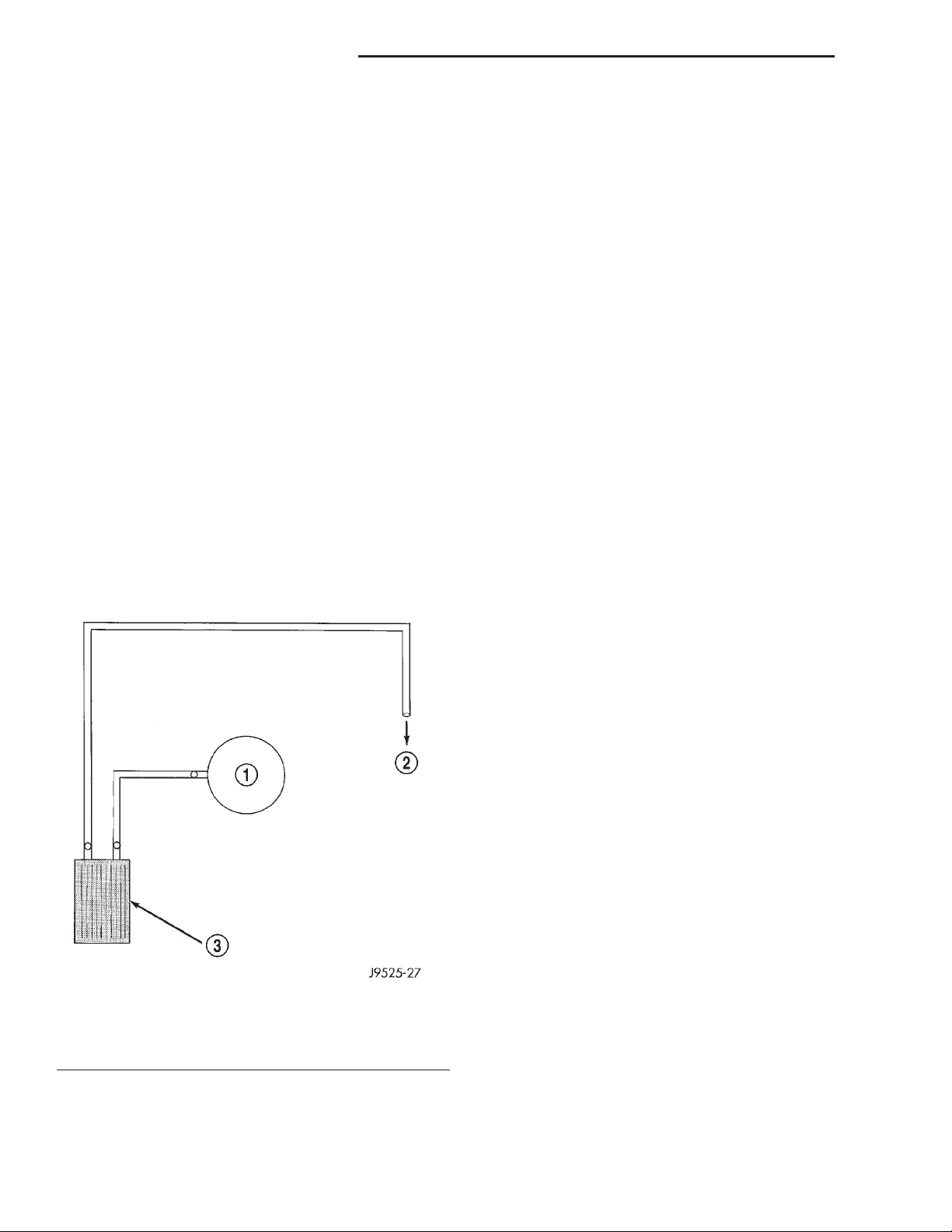
Vacuum for the EGR system is supplied by the
internal engine mounted vacuum pump. Refer to
EGR System Operation for vacuum pump information. Vacuum harness routing for emission related
components is displayed in (Fig. 1).
Fig. 1 Typical Hose Routing
1 – EGR VALVE
2 – TO VACUUM PUMP
3 – ELECTRIC VACUUM MODULATOR (EVM)
REMOVAL AND INSTALLATION
EGRVALVE..............................7
EGR TUBE...............................7
ELECTRIC VACUUM MODULATOR (EVM) .......8
SPECIFICATIONS
TORQUE CHART—2.5L DIESEL ..............8
EXHAUST GAS RECIRCULATION (EGR) SYSTEM
DESCRIPTION
The EGR system reduces oxides of nitrogen (NOx)
in the engine exhaust. This is accomplished by allowing a predetermined amount of hot exhaust gas to
recirculate and dilute the incoming fuel/air mixture.
A malfunctioning EGR system can cause engine
stumble, sags or hesitation, rough idle, engine stalling and poor driveability.
OPERATION
The system consists of:
• An EGR valve assembly. The valve is located on
the side of the intake manifold.
• An Electric Vacuum Modulator (EVM). The EVM
is sometimes referred to as the EGR control solenoid
or EGR duty cycle solenoid. The EVM controls the
“on time” of the EGR valve.
• The ECM operates the EVM. The ECM is
located inside the vehicle under the instrument
panel.
• An EGR tube connects a passage in the EGR
valve to the rear of the exhaust manifold.
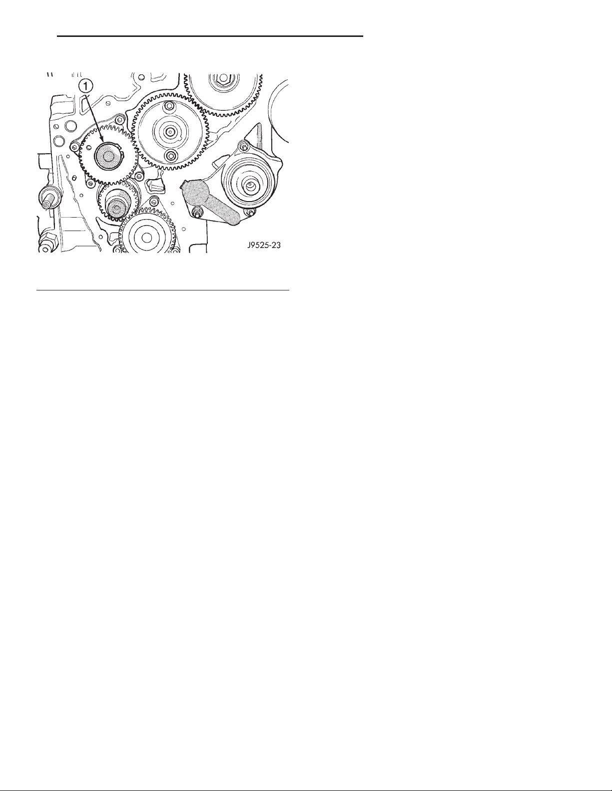
• The vacuum pump supplies vacuum for the
EVM and the EGR valve. This pump also supplies
vacuum for operation of the power brake boosterb
and the heating and air conditioning system. The
pump is located internally in the front of the engine
block (Fig. 2) and is driven by the crankshaft gear.
• Vacuum lines and hoses connect the various
components.
When the ECM supplies a variable ground signal
to the EVM, EGR system operation starts to occur.
The ECM will monitor and determine when to supply
and remove this variable ground signal. This will
depend on inputs from the engine coolant temperature, throttle position and engine speed sensors.
Page 7
XJ EMISSION CONTROL SYSTEM 25 - 7
DESCRIPTION AND OPERATION (Continued)
REMOVAL AND INSTALLATION
EGR VALVE
REMOVAL
(1) Disconnect vacuum line at EGR valve vacuum
supply fitting.
(2) Loosen the tube fitting at exhaust manifold end
of EGR tube.
(3) Remove the two bolts retaining the EGR tube
to the EGR valve and remove the EGR tube.
(4) Remove the two bolts retaining the EGR valve
to the intake manifold elbow and remove EGR valve.
(5) Discard both of the old EGR mounting gaskets.
Fig. 2 Internal Vacuum Pump
1 – INTERNAL VACUUM PUMP AND DRIVE GEAR
When the variable ground signal is supplied to the
EVM, vacuum from the vacuum pump will be
allowed to pass through the EVM and on to the EGR
valve with a connecting hose.
Exhaust gas recirculation will begin in this order
when:
• The ECM determines that EGR system opera-
tion is necessary.
• The engine is running to operate the vacuum
pump.
• A variable ground signal is supplied to the EVM.
• Variable vacuum passes through the EVM to the
EGR valve.
• The inlet seat (poppet valve) at the bottom of
the EGR valve opens to dilute and recirculate
exhaust gas back into the intake manifold.
The EGR system will be shut down by the ECM
after 60 seconds of continuous engine idling to
improve idle quality.
DIAGNOSIS AND TESTING
EGR GAS FLOW TEST
Refer to the 2000 XJ Diesel Powertrain Diagnostic
Manual for complete test procedure.
INSTALLATION
(1) Clean the intake manifold of any old gasket
material.
(2) Clean the end of EGR tube of any old gasket
material.
(3) Position the EGR valve and new gasket to the
intake manifold elbow.
(4) Install two EGR valve mounting bolts. Do not
tighten bolts at this time.
(5) Position new gasket between EGR valve and
EGR tube.
(6) Install two EGR tube bolts. Tighten all four
mounting bolts to 23 N·m (204 in. lbs.).
(7) Tighten EGR tube fitting at exhaust manifold.
(8) Connect vacuum line to EGR valve.
EGR TUBE
The EGR tube connects the EGR valve to the rear
of the exhaust manifold.
REMOVAL
(1) Remove two EGR tube mounting bolts at EGR
valve end of tube.
(2) Loosen fitting at exhaust manifold end of tube.
(3) Remove EGR tube and discard old gasket.
(4) Clean gasket mating surfaces and EGR tube
flange gasket surfaces.
(5) Check for signs of leakage or cracked surfaces
at both ends of tube, exhaust manifold and EGR
valve.
EGR SOLENOID TEST
VACUUM TEST
With the engine running, disconnect the vacuum
supply line at the fitting on the Electric Vacuum
Modulator (EVM). Vacuum should be no less than 20
inches. If vacuum is lower, check for leaks in vacuum
supply line. If leaks cannot be found, check for low
vacuum at vacuum pump.
INSTALLATION
(1) Install a new gasket to EGR valve end of EGR
tube.
(2) Position EGR tube to engine.
(3) Loosely tighten fitting at exhaust manifold end
of tube.
(4) Install 2 mounting bolts at EGR valve end of
tube. Tighten bolts to 23 N·m (204 in. lbs.) torque.
(5) Tighten fitting at exhaust manifold end of tube.
Page 8
25 - 8 EMISSION CONTROL SYSTEM XJ
REMOVAL AND INSTALLATION (Continued)
ELECTRIC VACUUM MODULATOR (EVM)
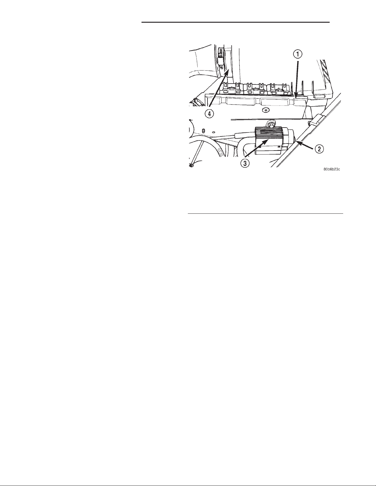
The EVM (EGR Duty Cycle Solenoid) is mounted
behind the PCM.
REMOVAL
(1) Disconnect the negative battery cable.
(2) Disconnect two vacuum hoses at EVM (Fig. 3).
(3) Remove mounting screws of EVM (Fig. 3).
(4) Remove the EVM to gain access to the EVM
electrical connector.
(5) Remove electrical connector at EVM.
INSTALLATION
(1) Install electrical connector to EVM.
(2) Install EVM and tighten mounting screws (Fig.
3).
(3) Connect vacuum hoses (Fig. 3).
(4) Connect the negative battery cable.
Fig. 3 Electric Vacuum Modulator (EVM)
SPECIFICATIONS
TORQUE CHART—2.5L DIESEL
1 – POWERTRAIN CONTROL MODULE (PCM)
2 – EVM HARNESS CONNECTOR
3 – ELECTRIC VACUUM MODULATOR (EVM)
4 – AIR CLEANER HOUSING
Description Torque
EGR Valve Mounting Bolts . . . 23 N·m (204 in. lbs.)
EGR Tube Mounting Bolts . . . 23 N·m (204 in. lbs.)
EVM Mounting Bolt .......... 2N·m(20in.lbs.)
 Loading...