

Page 1

XJ HEATING AND AIR CONDITIONING 24 - 1
HEATING AND AIR CONDITIONING
TABLE OF CONTENTS
page page
DESCRIPTION AND OPERATION
ACCUMULATOR ..........................2
BLOWER MOTOR .........................2
BLOWER MOTOR RELAY...................2
BLOWER MOTOR RESISTOR................3
BLOWER MOTOR SWITCH..................3
COMPRESSOR ...........................3
COMPRESSOR CLUTCH....................3
COMPRESSOR CLUTCH RELAY..............4
CONDENSER.............................4
DUAL FUNCTION HIGH PRESSURE SWITCH
(4.0 L) ................................4
EVAPORATOR COIL .......................4
FIXED ORIFICE TUBE......................5
HEATER AND AIR CONDITIONER.............5
HEATER AND AIR CONDITIONER CONTROL....6
HEATER CORE ...........................6
HIGH PRESSURE CUT-OFF SWITCH ..........6
HIGH PRESSURE RELIEF VALVE .............7
LOW PRESSURE CYCLING CLUTCH SWITCH...7
REFRIGERANT ...........................7
REFRIGERANT LINES......................7
REFRIGERANT LINE COUPLERS .............8
REFRIGERANT OIL ........................8
REFRIGERANT SYSTEM SERVICE PORT.......9
VACUUM CHECK VALVE....................9
VACUUM RESERVOIR .....................9
DIAGNOSIS AND TESTING
A/C PERFORMANCE .......................9
BLOWER MOTOR ........................12
BLOWER MOTOR RELAY..................13
BLOWER MOTOR RESISTOR...............14
BLOWER MOTOR SWITCH.................14
COMPRESSOR ..........................14
COMPRESSOR CLUTCH COIL ..............15
COMPRESSOR CLUTCH RELAY.............15
DUAL FUNCTION HIGH PRESSURE
SWITCH/HIGH PRESSURE CUT-OFF
SWITCH..............................16
HEATER PERFORMANCE ..................16
LOW PRESSURE CYCLING CLUTCH SWITCH. . 17
REFRIGERANT SYSTEM LEAKS.............17
VACUUM SYSTEM .......................18
SERVICE PROCEDURES
REFRIGERANT OIL LEVEL .................19
REFRIGERANT RECOVERY.................22
REFRIGERANT SYSTEM EVACUATE..........22
REFRIGERANT SYSTEM CHARGE ...........22
REFRIGERANT SYSTEM SERVICE
EQUIPMENT...........................22
REMOVAL AND INSTALLATION
SERVICE WARNINGS AND PRECAUTIONS ....23
ACCUMULATOR .........................25
BLEND-AIR DOOR MOTOR ................26
BLOWER MOTOR ........................26
BLOWER MOTOR RELAY..................27
BLOWER MOTOR RESISTOR...............27
COMPRESSOR ..........................28
COMPRESSOR CLUTCH...................29
COMPRESSOR CLUTCH RELAY.............31
CONDENSER............................32
DUAL FUNCTION HIGH PRESSURE
SWITCH/HIGH PRESSURE CUT-OFF
SWITCH..............................33
DUCTS AND OUTLETS....................33
EVAPORATOR COIL ......................35
FIXED ORIFICE TUBE.....................35
HEATER-A/C CONTROL ...................35
HEATER-A/C HOUSING....................36
HEATER-A/C HOUSING DOOR ..............39
HEATER CORE ..........................41
LIQUID LINE............................41
LOW PRESSURE CYCLING CLUTCH SWITCH. . 42
KICK COVER............................42
MODE DOOR VACUUM ACTUATOR..........43
REFRIGERANT LINE COUPLER .............45
SUCTION AND DISCHARGE LINE ...........45
VACUUM CHECK VALVE...................46
VACUUM RESERVOIR ....................47
SPECIFICATIONS
A/C APPLICATION TABLE..................47
Page 2
24 - 2 HEATING AND AIR CONDITIONING XJ
DESCRIPTION AND OPERATION
ACCUMULATOR
DESCRIPTION
The accumulator is mounted in the engine compartment between the evaporator coil outlet tube and
the compressor inlet.
OPERATION
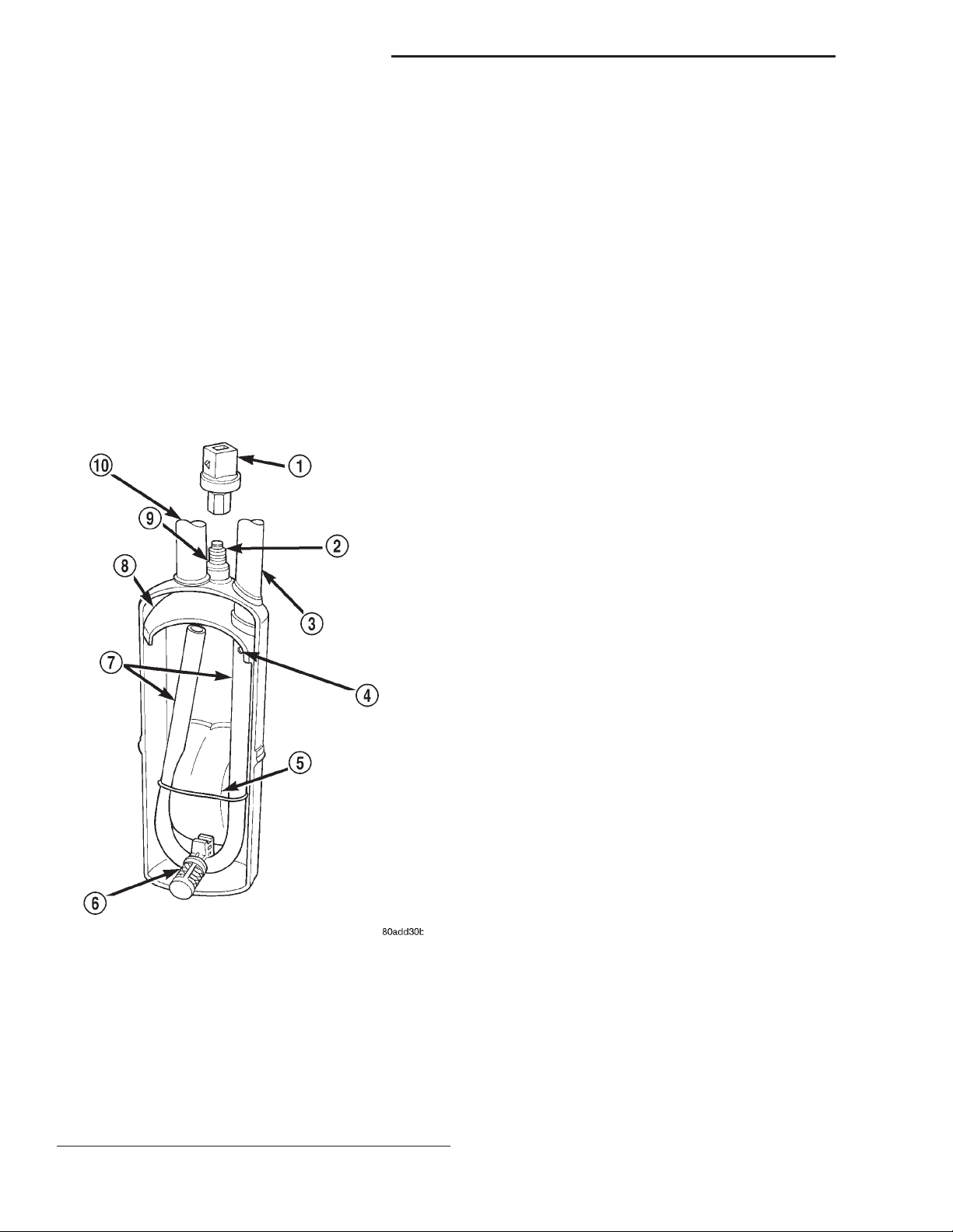
Refrigerant enters the accumulator canister as a
low pressure vapor through the inlet tube. Any liquid, oil-laden refrigerant falls to the bottom of the
canister, which acts as a separator. A desiccant bag is
mounted inside the accumulator canister to absorb
any moisture which may have entered and become
trapped within the refrigerant system (Fig. 1).
BLOWER MOTOR
DESCRIPTION
The blower motor and blower wheel are located in
the passenger side end of the heater-A/C housing,
below the glove box. The blower motor controls the
velocity of air flowing through the heater-A/C housing by spinning a squirrel cage-type blower wheel
within the housing at the selected speed. The blower
motor and wheel can be removed through an opening
in the engine compartment side of the dash panel
without heater-A/C housing removal.
OPERATION
The blower motor will only operate when the ignition switch is in the On position, and the heater-A/C
mode control switch knob is in any position, except
Off. The blower motor receives a fused battery feed
through the blower motor relay whenever the ignition switch is in the On position. The blower motor
battery feed circuit is protected by a fuse in the
Power Distribution Center (PDC). Blower motor
speed is controlled by regulating the ground path
through the heater-A/C control blower motor switch
and the blower motor resistor.
The blower motor and blower motor wheel cannot
be repaired and, if faulty or damaged, they must be
replaced. The blower motor and blower wheel are serviced only as a unit.
Fig. 1 Accumulator - Typical
1 – LOW PRESSURE CYCLING CLUTCH SWITCH
2 – PRESSURE SWITCH FITTING
3 – OUTLET TO COMPRESSOR
4 – ANTI-SIPHON HOLE
5 – DESICCANT BAG
6 – OIL RETURN ORIFICE FILTER
7 – VAPOR RETURN TUBE
8 – ACCUMULATOR DOME
9 – O-RING SEAL
10 – INLET FROM EVAPORATOR
BLOWER MOTOR RELAY
DESCRIPTION
The blower motor relay is a International Standards Organization (ISO)-type relay. The relay is a
electromechanical device that switches battery current from a fuse in the Power Distribution Center
(PDC) directly to the blower motor. The relay is energized when the relay coil is provided a voltage signal
by the ignition switch. See Blower Motor Relay in the
Diagnosis and Testing section of this group for more
information.
OPERATION
The blower motor relay is installed in a wire harness connector that is secured to the passenger side
outboard end of the heater-A/C housing in the passenger compartment, next to the heater-A/C wire
harness connector.
The blower motor relay cannot be repaired and, if
faulty or damaged, it must be replaced.
Page 3
XJ HEATING AND AIR CONDITIONING 24 - 3
DESCRIPTION AND OPERATION (Continued)
BLOWER MOTOR RESISTOR
DESCRIPTION
The blower motor resistor is mounted to the bottom of the heater-A/C housing on the passenger side
of the vehicle under the instrument panel. It can be
accessed for service by removing the heater-A/C
housing kick cover.
OPERATION
The resistor has multiple resistor wires, each of
which reduce the current flow to the blower motor, to
change the blower motor speed. The blower motor
switch directs the ground path through the correct
resistor wire to obtain the selected speed. When the
highest blower speed is selected, the blower motor
switch connects the blower motor directly to ground,
bypassing the blower motor resistor.
The blower motor resistor cannot be repaired and,
if faulty or damaged, it must be replaced.
BLOWER MOTOR SWITCH
DESCRIPTION
The heater-only or heater-A/C blower motor is controlled by a four position rotary-type blower motor
switch, mounted in the heater-A/C control panel. The
switch allows the selection of one of four blower
motor speeds, but can only be turned off by selecting
the Off position with the heater-A/C mode control
switch knob.
The compressor is lubricated by refrigerant oil that is
circulated throughout the refrigerant system with the
refrigerant.
The compressor draws in low-pressure refrigerant
vapor from the evaporator through its suction port. It
then compresses the refrigerant into a high-pressure,
high-temperature refrigerant vapor, which is then
pumped to the condenser through the compressor discharge port.
The compressor cannot be repaired. If faulty or
damaged, the entire compressor assembly must be
replaced. The compressor clutch, pulley and clutch
coil are available for service.
COMPRESSOR CLUTCH
DESCRIPTION
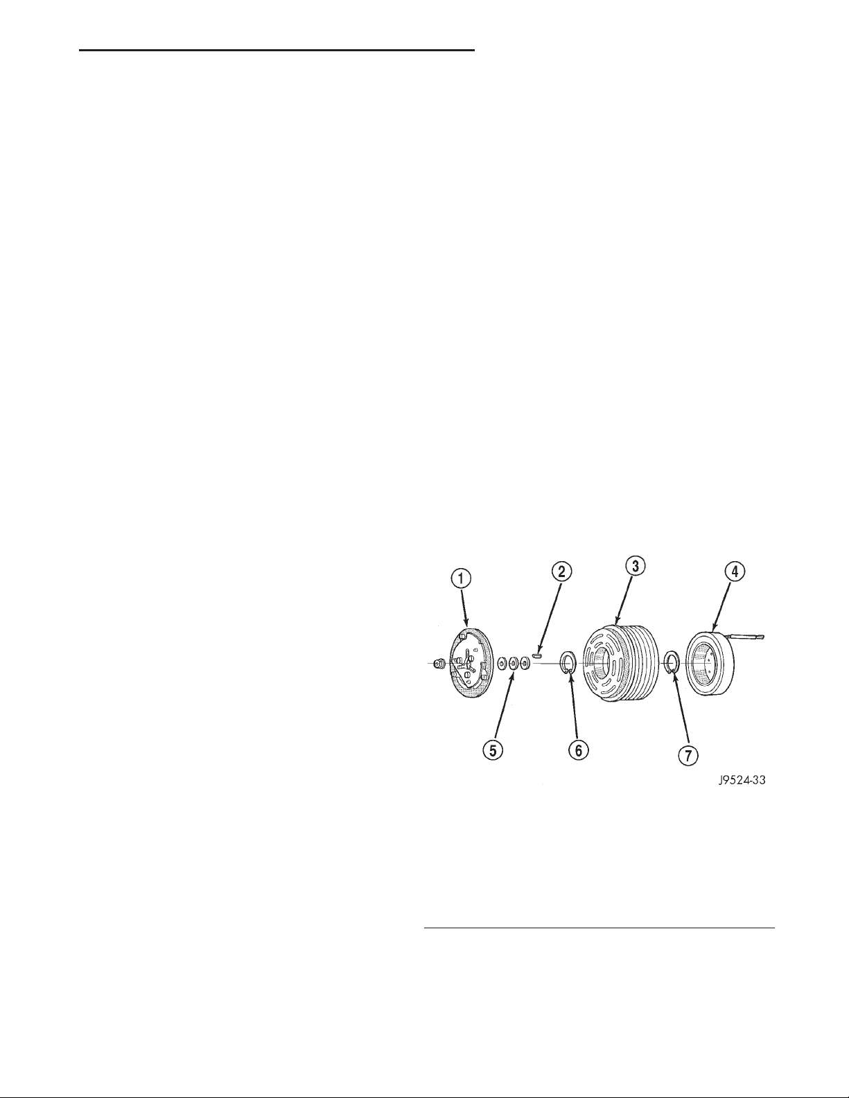
The compressor clutch assembly consists of a stationary electromagnetic coil, a hub bearing and pulley assembly, and a clutch plate (Fig. 2). The
electromagnetic coil unit and the hub bearing and
pulley assembly are each retained on the nose of the
compressor front housing with snap rings. The clutch
plate is keyed to the compressor shaft and secured
with a nut. These components provide the means to
engage and disengage the compressor from the
engine serpentine accessory drive belt.
OPERATION
The blower motor switch directs the blower motor
ground path through the mode control switch to the
blower motor resistor, or directly to ground, as
required to achieve the selected blower motor speed.
The blower motor switch cannot be repaired and, if
faulty or damaged, the entire heater-only or heaterA/C control unit must be replaced.
COMPRESSOR
DESCRIPTION
The air conditioning system uses a Sanden
SD7H15 seven cylinder, reciprocating wobble platetype compressor on all models. This compressor has a
fixed displacement of 150 cubic centimeters (9.375
cubic inches), and has both the suction and discharge
ports located on the cylinder head. A label identifying
the use of R-134a refrigerant is located on the compressor.
OPERATION
The compressor is driven by the engine through an
electric clutch, drive pulley and belt arrangement.
Fig. 2 Compressor Clutch - Typical
1 – CLUTCH PLATE
2 – SHAFT KEY
3 – PULLEY
4 – COIL
5 – CLUTCH SHIMS
6 – SNAP RING
7 – SNAP RING
OPERATION
When the clutch coil is energized, it magnetically
draws the clutch into contact with the pulley and
drives the compressor shaft. When the coil is not
energized, the pulley freewheels on the clutch hub
Page 4

24 - 4 HEATING AND AIR CONDITIONING XJ
DESCRIPTION AND OPERATION (Continued)
bearing, which is part of the pulley. The compressor
clutch and coil are the only serviced parts on the
compressor.
The compressor clutch engagement is controlled by
several components: the heater-A/C mode control
switch, the low pressure cycling clutch switch, the
high pressure cut-off switch, the compressor clutch
relay, and the Powertrain Control Module (PCM).
The PCM may delay compressor clutch engagement
for up to thirty seconds. Refer to Group 14 - Fuel
System for more information on the PCM controls.
COMPRESSOR CLUTCH RELAY
DESCRIPTION
The compressor clutch relay is a International
Standards Organization (ISO) micro-relay. The terminal designations and functions are the same as a conventional ISO relay. However, the micro-relay
terminal orientation (footprint) is different, the current capacity is lower, and the relay case dimensions
are smaller than those of the conventional ISO relay.
The compressor clutch relay is located in the Power
Distribution Center (PDC) in the engine compartment. Refer to the PDC label for relay identification
and location.
OPERATION
The compressor clutch relay is a electromechanical
device that switches battery current to the compressor clutch coil when the Powertrain Control Module
(PCM) grounds the coil side of the relay. The PCM
responds to inputs from the heater-A/C mode control
switch, the low pressure cycling clutch switch, and
the high pressure cut-off switch. See Compressor
Clutch Relay in the Diagnosis and Testing section of
this group for more information.
The compressor clutch relay cannot be repaired
and, if faulty or damaged, it must be replaced.
CONDENSER
DESCRIPTION
The condenser is located in the air flow in front of
the engine cooling radiator. The condenser is a heat
exchanger that allows the high-pressure refrigerant
gas being discharged by the compressor to give up its
heat to the air passing over the condenser fins.
OPERATION
When the refrigerant gas gives up its heat, it condenses. When the refrigerant leaves the condenser, it
has become a high-pressure liquid refrigerant. The
volume of air flowing over the condenser fins is critical to the proper cooling performance of the air conditioning system. Therefore, it is important that
there are no objects placed in front of the radiator
grille openings in the front of the vehicle or foreign
material on the condenser fins that might obstruct
proper air flow. Also, any factory-installed air seals or
shrouds must be properly reinstalled following radiator or condenser service.
The condenser cannot be repaired and, if faulty or
damaged, it must be replaced.
DUAL FUNCTION HIGH PRESSURE SWITCH (4.0 L)
DESCRIPTION
The Dual Function High Pressure Switch controls
both A/C clutch engagement/disengagement, and electric cooling fan operations. The switch is located on
the discharge line near the compressor. The switch is
screwed onto a fitting that contains a Schrader-type
valve, which allows the switch to be serviced without
discharging the refrigerant system. The discharge
line fitting is equipped with an O-ring to seal the
switch connection.
OPERATION
The dual function switch is connected in series
electrically with the low pressure cycling clutch
switch between ground and the Powertrain Control
Module (PCM). The switch contacts open and close
causing the PCM to turn the compressor clutch on
and off. This prevents compressor operation when the
discharge line pressure approaches high levels, and
also reduces electrical surging from compressor
clutch engagement.
The dual function switch controls the electric cooling fan operation by monitoring refrigerant line pressures. When the discharge line pressure rises above
1900 to 2200 kPa (280 to 320 psi) the fan will turn
on. The cooling fan will turn off when the discharge
line pressure drops to 1600 kPa (235 psi).
The dual function switch controls the A/C clutch
operation by disengaging the clutch when the discharge line pressure rises above 3100 to 3375 kPa
(450 to 490 psi). The switch contacts will close and
allow A/C clutch engagement when the discharge line
pressure drops to 1860 to 2275 kPa (270 to 330 psi).
The Dual Function High Pressure Switch is a factory-calibrated unit. The switch cannot be adjusted
or repaired and, if faulty or damaged, it must be
replaced.
EVAPORATOR COIL
DESCRIPTION
The evaporator coil is located in the heater-A/C
housing, under the instrument panel. The evaporator
coil is positioned in the heater-A/C housing so that
Page 5
XJ HEATING AND AIR CONDITIONING 24 - 5
DESCRIPTION AND OPERATION (Continued)
all air that enters the housing must pass over the
fins of the evaporator before it is distributed through
the system ducts and outlets. However, air passing
over the evaporator coil fins will only be conditioned
when the compressor is engaged and circulating
refrigerant through the evaporator coil tubes.
OPERATION
Refrigerant enters the evaporator from the fixed
orifice tube as a low-temperature, low-pressure liquid. As air flows over the fins of the evaporator, the
humidity in the air condenses on the fins, and the
heat from the air is absorbed by the refrigerant. Heat
absorption causes the refrigerant to boil and vaporize. The refrigerant becomes a low-pressure gas when
it leaves the evaporator.
The evaporator coil cannot be repaired and, if
faulty or damaged, it must be replaced.
FIXED ORIFICE TUBE
DESCRIPTION
The fixed orifice tube is installed in the liquid line
(left-hand drive) or liquid line jumper (right-hand
drive) between the outlet of the condenser and the
inlet of the evaporator. The fixed orifice tube is
located in the end of the liquid line or liquid line
jumper that is closest to the condenser outlet tube.
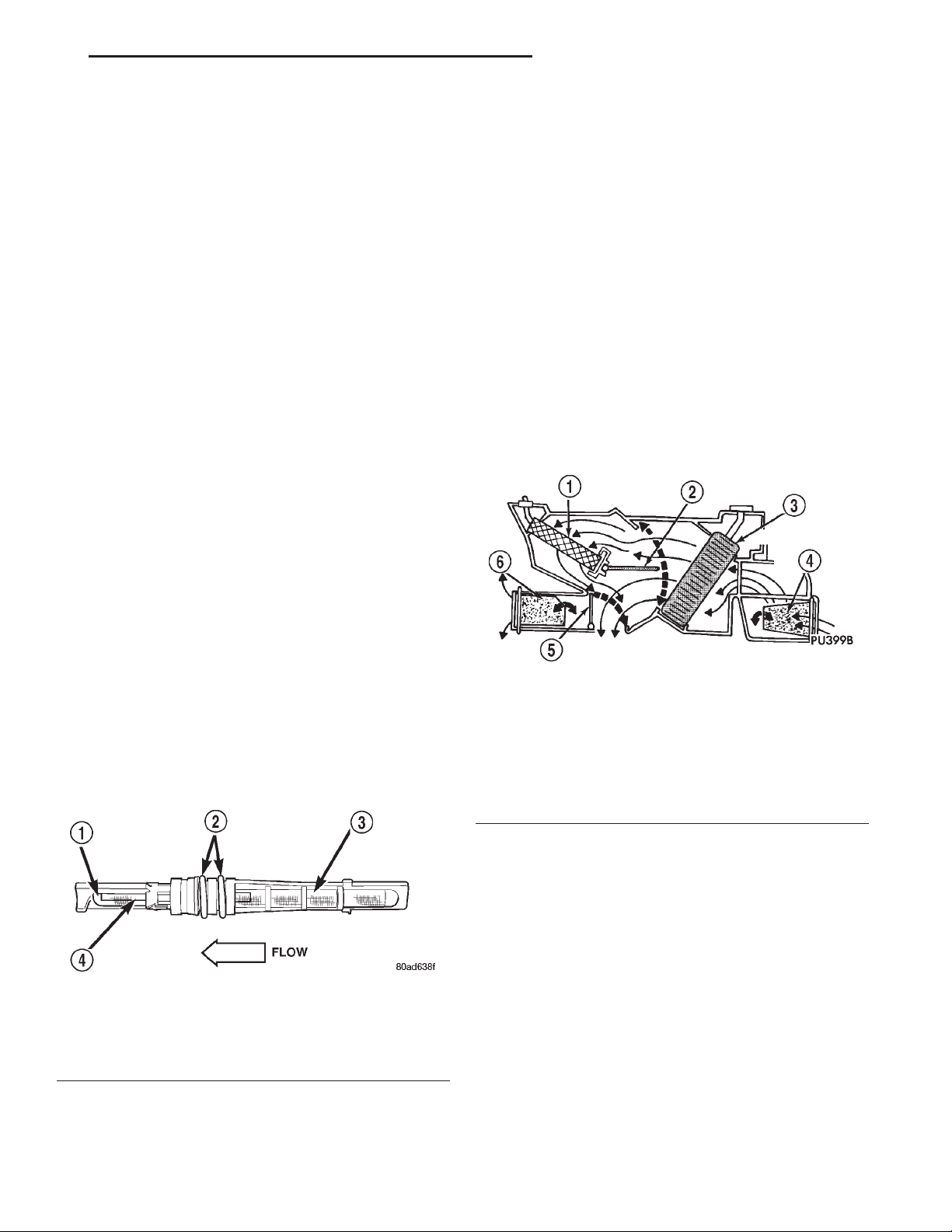
The inlet end of the fixed orifice tube has a nylon
mesh filter screen, which filters the refrigerant and
helps to reduce the potential for blockage of the
metering orifice by refrigerant system contaminants
(Fig. 3). The outlet end of the tube has a nylon mesh
diffuser screen. The O-rings on the plastic body of
the fixed orifice tube seal the tube to the inside of
the liquid line and prevent the refrigerant from
bypassing the fixed metering orifice.
pressure liquid refrigerant from the condenser
expands into a low-pressure liquid as it passes
through the metering orifice and diffuser screen of
the fixed orifice tube.
The fixed orifice tube cannot be repaired and, if
faulty or plugged, the liquid line and fixed orifice
tube unit or liquid line jumper and fixed orifice tube
unit must be replaced.
HEATER AND AIR CONDITIONER
DESCRIPTION
All vehicles are equipped with a common heaterA/C housing assembly (Fig. 4). The system combines
air conditioning, heating, and ventilating capabilities
in a single unit housing mounted under the instrument panel. On heater-only systems, the evaporator
coil and recirculating air door are omitted from the
housing.
Fig. 4 Common Blend-Air Heater-Air Conditioner
System - Typical
1 – HEATER CORE
2 – BLEND-AIR DOOR
3 – EVAPORATOR A/C ONLY
4 – RECIRCULATINGAIR DOOR A/C ONLY
5 – FLOOR/PANEL DOOR
6 – FLOOR/DEFROST DOOR
Fig. 3 Fixed Orifice Tube - Typical
1 – DIFFUSER SCREEN
2 – “O” RINGS
3 – INLET FILTER SCREEN
4 – ORIFICE
OPERATION
The fixed orifice tube is used to meter the flow of
liquid refrigerant into the evaporator coil. The high-
Outside fresh air enters the vehicle through the
cowl top opening at the base of the windshield, and
passes through a plenum chamber to the heater-A/C
system blower housing. Air flow velocity can then be
adjusted with the blower motor speed selector switch
on the heater-A/C control panel. The air intake openings must be kept free of snow, ice, leaves, and other
obstructions for the heater-A/C system to receive a
sufficient volume of outside air.
It is also important to keep the air intake openings
clear of debris because leaf particles and other debris
that is small enough to pass through the cowl plenum screen can accumulate within the heater-A/C
housing. The closed, warm, damp and dark environment created within the heater-A/C housing is ideal
for the growth of certain molds, mildews and other
fungi. Any accumulation of decaying plant matter
Page 6

24 - 6 HEATING AND AIR CONDITIONING XJ
DESCRIPTION AND OPERATION (Continued)
provides an additional food source for fungal spores,
which enter the housing with the fresh air. Excess
debris, as well as objectionable odors created by
decaying plant matter and growing fungi can be discharged into the passenger compartment during
heater-A/C system operation.
OPERATION
The heater and optional air conditioner are blendair type systems. In a blend-air system, a blend-air
door controls the amount of unconditioned air (or
cooled air from the evaporator on models with air
conditioning) that is allowed to flow through, or
around, the heater core. A temperature control knob
on the heater-A/C control panel determines the discharge air temperature by controlling an electric
motor, which moves the blend-air door. This allows
an almost immediate control of the output air temperature of the system.
The mode control knob on the heater-only or heater-A/C control panel is used to direct the conditioned
air to the selected system outlets. Both mode control
switches use engine vacuum to control the mode
doors, which are operated by vacuum actuator
motors.
On air conditioned vehicles, the outside air intake
can be shut off by selecting the Recirculation Mode
with the mode control knob. This will operate a vacuum actuated recirculating air door that closes off
the outside fresh air intake and recirculates the air
that is already inside the vehicle.
The optional air conditioner for all models is
designed for the use of non-CFC, R-134a refrigerant.
The air conditioning system has an evaporator to cool
and dehumidify the incoming air prior to blending it
with the heated air. This air conditioning system
uses a fixed orifice tube in the liquid line near the
condenser outlet tube to meter refrigerant flow to the
evaporator coil. To maintain minimum evaporator
temperature and prevent evaporator freezing, a fixed
pressure setting switch on the accumulator cycles the
compressor clutch.
HEATER AND AIR CONDITIONER CONTROL
DESCRIPTION
Both the heater-only and heater-A/C systems use a
combination of mechanical, electrical, and vacuum
controls. These controls provide the vehicle operator
with a number of setting options to help control the
climate and comfort within the vehicle. Refer to the
owner’s manual in the vehicle glove box for more
information on the features, use, and suggested operation of these controls.
OPERATION
The heater-only or heater-A/C control panel is
located to the right of the instrument cluster on the
instrument panel. The control panel contains a rotary-type temperature control knob, a rotary-type mode
control switch knob, and a rotary-type blower motor
speed switch knob.
The heater-only or heater-A/C control panel cannot
be repaired. If faulty or damaged, the entire unit
must be replaced. The illumination lamps are available for service replacement.
HEATER CORE
DESCRIPTION
The heater core is located in the heater-A/C housing, under the instrument panel. It is a heat
exchanger made of rows of tubes and fins.
OPERATION
Engine coolant is circulated through heater hoses
to the heater core at all times. As the coolant flows
through the heater core, heat removed from the
engine is transferred to the heater core fins and
tubes. Air directed through the heater core picks up
the heat from the heater core fins. The blend air door
allows control of the heater output air temperature
by controlling how much of the air flowing through
the heater-A/C housing is directed through the
heater core. The blower motor speed controls the volume of air flowing through the heater-A/C housing.
The heater core cannot be repaired and, if faulty or
damaged, it must be replaced. Refer to Group 7 Cooling System for more information on the engine
cooling system, the engine coolant and the heater
hoses.
HIGH PRESSURE CUT-OFF SWITCH
DESCRIPTION
The high pressure cut-off switch is located on the
discharge line between the compressor and the condenser inlet. The switch is screwed onto a fitting that
contains a Schrader-type valve, which allows the
switch to be serviced without discharging the refrigerant system. The discharge line fitting is equipped
with an O-ring to seal the switch connection.
OPERATION
The high pressure cut-off switch is connected in
series electrically with the low pressure cycling
clutch switch between ground and the Powertrain
Control Module (PCM). The switch contacts open and
close causing the PCM to turn the compressor clutch
on and off. This prevents compressor operation when
the discharge line pressure approaches high levels.
Page 7

XJ HEATING AND AIR CONDITIONING 24 - 7
DESCRIPTION AND OPERATION (Continued)
The high pressure cut-off switch contacts are open
when the discharge line pressure rises above 3100 to
3375 kPa (450 to 490 psi). The switch contacts will
close when the discharge line pressure drops to 1860
to 2275 kPa (270 to 330 psi).
The high pressure cut-off switch is a factory-calibrated unit. The switch cannot be adjusted or
repaired and, if faulty or damaged, it must be
replaced.
HIGH PRESSURE RELIEF VALVE
DESCRIPTION
A high pressure relief valve is located on the compressor manifold, which is on the side of the compressor. This mechanical valve is designed to vent
refrigerant from the system to protect against damage to the compressor and other system components,
caused by condenser air flow restriction or an overcharge of refrigerant.
OPERATION
The high pressure relief valve vents the system
when a discharge pressure of 3445 to 4135 kPa (500
to 600 psi) or above is reached. The valve closes
when a minimum discharge pressure of 2756 kPa
(400 psi) is reached.
The high pressure relief valve vents only enough
refrigerant to reduce the system pressure, and then
re-seats itself. The majority of the refrigerant is conserved in the system. If the valve vents refrigerant, it
does not mean that the valve is faulty.
The high pressure relief valve is a factory-calibrated unit. The valve cannot be adjusted or
repaired, and must not be removed or otherwise disturbed. The valve is only serviced as a part of the
compressor assembly.
LOW PRESSURE CYCLING CLUTCH SWITCH
DESCRIPTION
The low pressure cycling clutch switch is located
on the top of the accumulator. The switch is screwed
onto an accumulator fitting that contains a Schradertype valve, which allows the switch to be serviced
without discharging the refrigerant system. The
accumulator fitting is equipped with an O-ring to
seal the switch connection.
OPERATION
The low pressure cycling clutch switch is connected
in series electrically with the high pressure cut-off
switch, between ground and the Powertrain Control
Module (PCM). The switch contacts open and close
causing the PCM to turn the compressor clutch on
and off. This regulates the refrigerant system pres-
sure and controls evaporator temperature. Controlling the evaporator temperature prevents condensate
water on the evaporator fins from freezing and
obstructing air conditioning system air flow.
The low pressure cycling clutch switch contacts are
open when the suction pressure is approximately 141
kPa (20.5 psi) or lower. The switch contacts will close
when the suction pressure rises to approximately 234
to 262 kPa (34 to 38 psi) or above. Lower ambient
temperatures, below approximately -1° C (30° F), will
also cause the switch contacts to open. This is due to
the pressure/temperature relationship of the refrigerant in the system.
The low pressure cycling clutch switch is a factorycalibrated unit. It cannot be adjusted or repaired
and, if faulty or damaged, it must be replaced.
REFRIGERANT
DESCRIPTION
The refrigerant used in this air conditioning system is a HydroFluoroCarbon (HFC), type R-134a.
Unlike R-12, which is a ChloroFluoroCarbon (CFC),
R-134a refrigerant does not contain ozone-depleting
chlorine. R-134a refrigerant is a non-toxic, non-flammable, clear, and colorless liquefied gas.
Even though R-134a does not contain chlorine, it
must be reclaimed and recycled just like CFC-type
refrigerants. This is because R-134a is a greenhouse
gas and can contribute to global warming.
OPERATION
R-134a refrigerant is not compatible with R-12
refrigerant in an air conditioning system. Even a
small amount of R-12 added to an R-134a refrigerant
system will cause compressor failure, refrigerant oil
sludge or poor air conditioning system performance.
In addition, the PolyAlkylene Glycol (PAG) synthetic
refrigerant oils used in an R-134a refrigerant system
are not compatible with the mineral-based refrigerant oils used in an R-12 refrigerant system.
R-134a refrigerant system service ports, service
tool couplers and refrigerant dispensing bottles have
all been designed with unique fittings to ensure that
an R-134a system is not accidentally contaminated
with the wrong refrigerant (R-12). There are also
labels posted in the engine compartment of the vehicle and on the compressor identifying to service technicians that the air conditioning system is equipped
with R-134a.
REFRIGERANT LINES
DESCRIPTION
The refrigerant lines and hoses are used to carry
the refrigerant between the various air conditioning
Page 8
24 - 8 HEATING AND AIR CONDITIONING XJ
DESCRIPTION AND OPERATION (Continued)
system components. A barrier hose design with a
nylon tube, which is sandwiched between rubber layers, is used for the R-134a air conditioning system on
this vehicle. This nylon tube helps to further contain
the R-134a refrigerant, which has a smaller molecular structure than R-12 refrigerant. The ends of the
refrigerant hoses are made from lightweight aluminum or steel, and commonly use braze-less fittings.
Any kinks or sharp bends in the refrigerant plumbing will reduce the capacity of the entire air conditioning system. Kinks and sharp bends reduce the
flow of refrigerant in the system. A good rule for the
flexible hose refrigerant lines is to keep the radius of
all bends at least ten times the diameter of the hose.
In addition, the flexible hose refrigerant lines should
be routed so they are at least 80 millimeters (3
inches) from the exhaust manifold.
OPERATION
High pressures are produced in the refrigerant system when the air conditioning compressor is operating. Extreme care must be exercised to make sure
that each of the refrigerant system connections is
pressure-tight and leak free. It is a good practice to
inspect all flexible hose refrigerant lines at least once
a year to make sure they are in good condition and
properly routed.
The refrigerant lines and hoses are coupled with
other components of the HVAC system with peanutblock style fittings. A stat-O seal type flat steel gasket with a captured compressible O-ring, is used to
mate plumbing lines with A/C components to ensure
the integrity of the refrigerant system.
The refrigerant lines and hoses cannot be repaired
and, if faulty or damaged, they must be replaced.
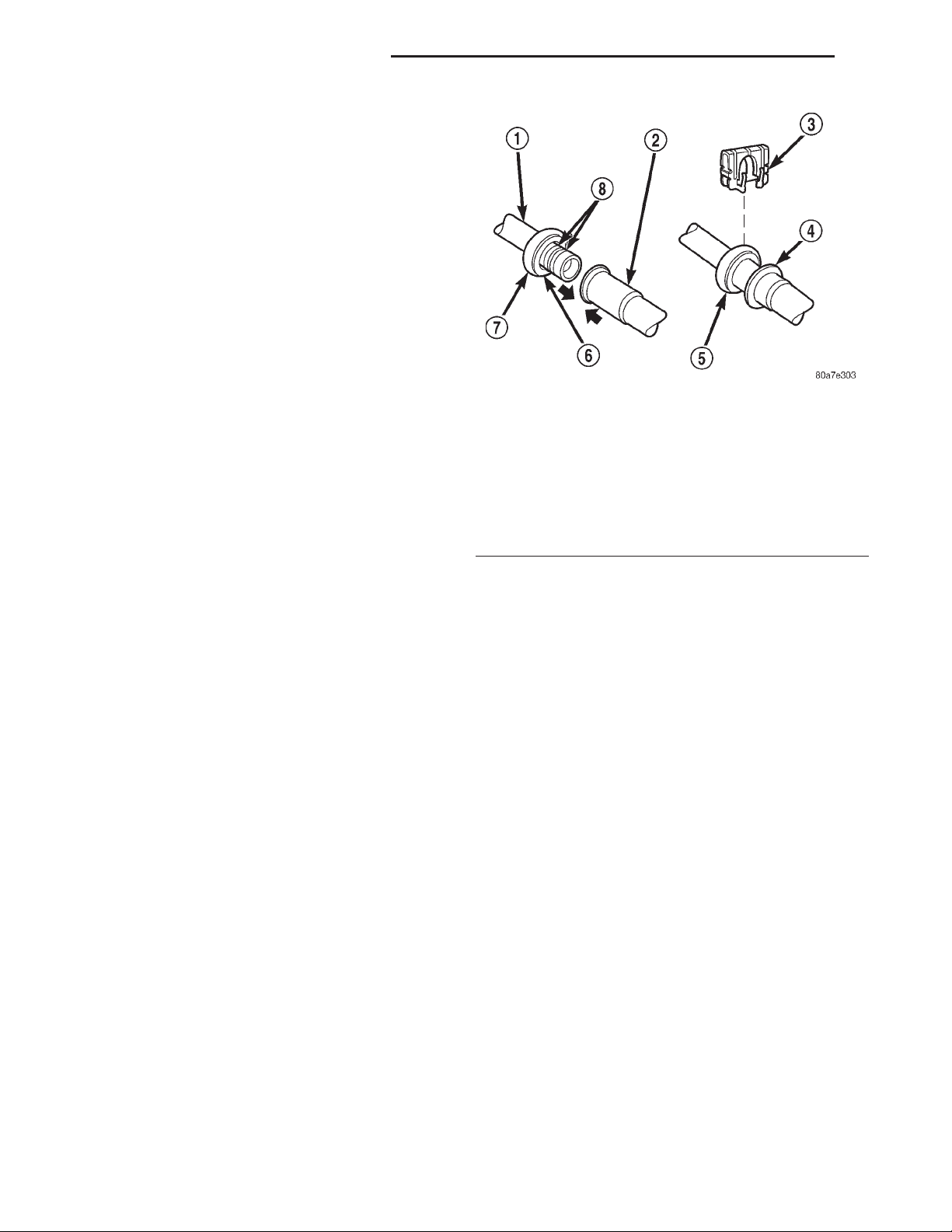
1 – MALE HALF SPRING-LOCK COUPLER
2 – FEMALE HALF SPRING-LOCK COUPLER
3 – SECONDARY CLIP
4 – CONNECTION INDICATOR RING
5 – COUPLER CAGE
6 – GARTER SPRING
7 – COUPLER CAGE
8 – “O” RINGS
patible with R-134a refrigerant and must be replaced
with O-rings made of the same material.
nected coupler halves at the factory for added blowoff
protection. In addition, some models have a plastic
ring that is used at the factory as a visual indicator
to confirm that these couplers are connected. After
the coupler is connected, the plastic indicator ring is
no longer needed; however, it will remain on the
refrigerant line near the coupler cage.
Fig. 5 Spring-Lock Coupler - Typical
Secondary clips are installed over the two con-
REFRIGERANT LINE COUPLERS
DESCRIPTION
Spring-lock type refrigerant line couplers are used
to connect many of the refrigerant lines and other
components to the refrigerant system. These couplers
require a special tool for disengaging the two coupler
halves.
OPERATION
The spring-lock coupler is held together by a garter
spring inside a circular cage on the male half of the
fitting (Fig. 5). When the two coupler halves are connected, the flared end of the female fitting slips
behind the garter spring inside the cage on the male
fitting. The garter spring and cage prevent the flared
end of the female fitting from pulling out of the cage.
Two O-rings on the male half of the fitting are
used to seal the connection. These O-rings are com-
REFRIGERANT OIL
DESCRIPTION
The refrigerant oil used in R-134a refrigerant systems is a synthetic-based, PolyAlkylene Glycol (PAG),
wax-free lubricant. Mineral-based R-12 refrigerant
oils are not compatible with PAG oils, and should
never be introduced to an R-134a refrigerant system.
There are different PAG oils available, and each
contains a different additive package. The 10PA17
compressor used in this vehicle is designed to use an
ND-8 PAG refrigerant oil. Use only refrigerant oil of
this same type to service the refrigerant system.
OPERATION
After performing any refrigerant recovery or recycling operation, always replenish the refrigerant system with the same amount of the recommended
refrigerant oil as was removed. Too little refrigerant
Page 9

XJ HEATING AND AIR CONDITIONING 24 - 9
DESCRIPTION AND OPERATION (Continued)
oil can cause compressor damage, and too much can
reduce air conditioning system performance.
PAG refrigerant oil is much more hygroscopic than
mineral oil, and will absorb any moisture it comes
into contact with, even moisture in the air. The PAG
oil container should always be kept tightly capped
until it is ready to be used. After use, recap the oil
container immediately to prevent moisture contamination.
REFRIGERANT SYSTEM SERVICE PORT
DESCRIPTION
The two refrigerant system service ports are used
to charge, recover/recycle, evacuate, and test the air
conditioning refrigerant system. Unique service port
coupler sizes are used on the R-134a system, to
ensure that the refrigerant system is not accidentally
contaminated by the use of the wrong refrigerant
(R-12), or refrigerant system service equipment.
OPERATION
The high pressure service port is located on the
refrigerant line, near the discharge port of the compressor. The low pressure service port is located on
the liquid line at the rear of the engine compartment,
near the evaporator inlet tube.
Each of the service ports has a threaded plastic
protective cap installed over it from the factory. After
servicing the refrigerant system, always reinstall
both of the service port caps.
VACUUM CHECK VALVE
DESCRIPTION
A vacuum check valve is installed in the accessory
vacuum supply line in the engine compartment, near
the vacuum tap on the engine intake manifold, and
at the HVAC unit takeout. The vacuum check valve
is designed to allow vacuum to flow in only one direction through the accessory vacuum supply circuits.
OPERATION
The use of a vacuum check valve helps to maintain
the system vacuum needed to retain the selected
heater-A/C mode settings. The check valve will prevent the engine from bleeding down system vacuum
through the intake manifold during extended heavy
engine load (low engine vacuum) operation.
The vacuum check valve cannot be repaired and, if
faulty or damaged, it must be replaced.
VACUUM RESERVOIR
DESCRIPTION
The vacuum reservoir is mounted to the front
bumper bar behind the passenger side bumper end
cap. The bumper end cap must be removed from the
vehicle to access the vacuum reservoir for service.
OPERATION
Engine vacuum is stored in the vacuum reservoir.
The stored vacuum is used to operate the vacuumcontrolled vehicle accessories during periods of low
engine vacuum such as when the vehicle is climbing
a steep grade, or under other high engine load operating conditions.
The vacuum reservoir cannot be repaired and, if
faulty or damaged, it must be replaced.
DIAGNOSIS AND TESTING
A/C PERFORMANCE
The air conditioning system is designed to provide
the passenger compartment with low temperature
and low humidity air. The evaporator, located in the
heater-A/C housing on the dash panel below the
instrument panel, is cooled to temperatures near the
freezing point. As warm damp air passes through the
cooled evaporator, the air transfers its heat to the
refrigerant in the evaporator and the moisture in the
air condenses on the evaporator fins. During periods
of high heat and humidity, an air conditioning system will be more effective in the Recirculation Mode.
With the system in the Recirculation Mode, only air
from the passenger compartment passes through the
evaporator. As the passenger compartment air dehumidifies, the air conditioning system performance
levels improve.
Humidity has an important bearing on the temperature of the air delivered to the interior of the vehicle. It is important to understand the effect that
humidity has on the performance of the air conditioning system. When humidity is high, the evaporator
has to perform a double duty. It must lower the air
temperature, and it must lower the temperature of
the moisture in the air that condenses on the evaporator fins. Condensing the moisture in the air transfers heat energy into the evaporator fins and tubing.
This reduces the amount of heat the evaporator can
absorb from the air. High humidity greatly reduces
the ability of the evaporator to lower the temperature
of the air.
Page 10
24 - 10 HEATING AND AIR CONDITIONING XJ
DIAGNOSIS AND TESTING (Continued)
However, evaporator capacity used to reduce the
amount of moisture in the air is not wasted. Wringing some of the moisture out of the air entering the
vehicle adds to the comfort of the passengers.
Although, an owner may expect too much from their
air conditioning system on humid days. A performance test is the best way to determine whether the
system is performing up to standard. This test also
provides valuable clues as to the possible cause of
trouble with the air conditioning system.
Review the Service Warnings and Precautions in
the front of this group before performing this procedure. The air temperature in the test room and in
the vehicle must be a minimum of 21° C (70° F) for
this test.
(1) Connect a tachometer and a manifold gauge
set.
(2) Set the heater-A/C mode control switch knob in
the Recirculation Mode position, the temperature
control knob in the full cool position, and the blower
motor switch knob in the highest speed position.
(3) Start the engine and hold the idle at 1,000 rpm
with the compressor clutch engaged.
(4) The engine should be at operating temperature.
The doors and windows must be open.
(5) Insert a thermometer in the driver side center
A/C (panel) outlet. Operate the engine for five minutes.
(6) The compressor clutch may cycle, depending
upon the ambient temperature and humidity. If the
clutch cycles, unplug the low pressure cycling clutch
switch wire harness connector from the switch
located on the accumulator (Fig. 6). Place a jumper
wire across the terminals of the low pressure cycling
clutch switch wire harness connector.
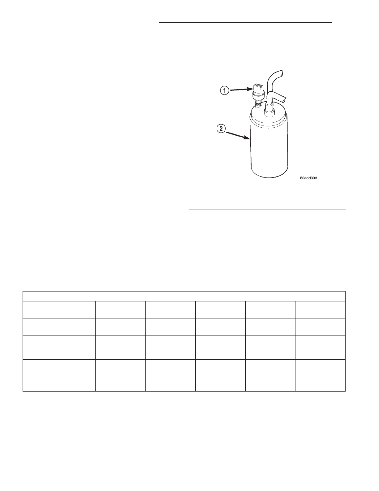
Fig. 6 Low Pressure Cycling Clutch Switch - Typical
1 – LOW PRESSURE CYCLING CLUTCH SWITCH
2 – ACCUMULATOR
(7) With the compressor clutch engaged, record the
discharge air temperature and the compressor discharge pressure.
(8) Compare the discharge air temperature to the
Performance Temperature and Pressure chart. If the
discharge air temperature is high, see Refrigerant
System Leaks and Refrigerant System Charge in this
group.
Performance Temperature and Pressure
Ambient Air
Temperature
Air Temperature at
Center Panel Outlet
Evaporator Inlet
Pressure at Charge
Port
Compressor Discharge
Pressure
21° C
(70° F)
-3 to 3° C
(27 to 38° F)
179 to 241 kPa
(26 to 35 psi)
1240 to 1655
kPa
(180 to 240
psi)
27° C
(80° F)
1to7°C
(33 to 44° F)
221 to 283
kPa
(32 to 41 psi)
1380 to 1790
kPa
(200 to 260
psi)
(9) Compare the compressor discharge pressure to
the Performance Temperature and Pressure chart. If
the compressor discharge pressure is high, see the
Pressure Diagnosis chart.
32° C
(90° F)
3to9°C
(37 to 48° F)
262 to 324
kPa
(38 to 47 psi)
1720 to 2070
kPa
(250 to 300
psi)
38° C
(100° F)
6 to 13° C
(43 to 55° F)
303 to 365
kPa
(44 to 53 psi)
1860 to 2345
kPa
(270 to 340
psi)
43° C
(110° F)
10 to 18° C
(50 to 64° F)
345 to 414 kPa
(50 to 60 psi)
2070 to 2690
kPa
(300 to 390 psi)
Page 11
XJ HEATING AND AIR CONDITIONING 24 - 11
DIAGNOSIS AND TESTING (Continued)
Pressure Diagnosis
Condition Possible Causes Correction
Rapid compressor clutch
cycling (ten or more cycles
per minute).
Equal pressures, but the
compressor clutch does not
engage.
Normal pressures, but A/C
Performance Test air
temperatures at center panel
outlet are too high.
The low side pressure is
normal or slightly low, and
the high side pressure is too
low.
1. Low refrigerant system
charge.
1. No refrigerant in the
refrigerant system.
2. Faulty fuse.
3. Faulty compressor clutch
coil.
4. Faulty compressor clutch
relay.
5. Improperly installed or
faulty low pressure cycling
clutch switch.
6. Faulty high pressure
cut-off switch.
7. Faulty Powertrain Control
Module (PCM).
1. Excessive refrigerant oil in
system.
2. Blend-Air door inoperative
or sealing improperly.
3. Blend-Air door motor faulty
or inoperative.
1. Low refrigerant system
charge.
2. Refrigerant flow through
the accumulator is restricted.
3. Refrigerant flow through
the evaporator coil is
restricted.
4. Faulty compressor.
1. See Refrigerant System Leaks in this group.
Test the refrigerant system for leaks. Repair,
evacuate and charge the refrigerant system, if
required.
1. See Refrigerant System Leaks in this group.
Test the refrigerant system for leaks. Repair,
evacuate and charge the refrigerant system, if
required.
2. Check the fuses in the Power Distribution
Center and the junction block. Repair the shorted
circuit or component and replace the fuses, if
required.
3. See Compressor Clutch Coil in this group. Test
the compressor clutch coil and replace, if
required.
4. See Compressor Clutch Relay in this group.
Test the compressor clutch relay and relay
circuits. Repair the circuits or replace the relay, if
required.
5. See Low Pressure Cycling Clutch Switch in
this group. Test the low pressure cycling clutch
switch and tighten or replace, if required.
6. See High Pressure Cut-Off Switch in this
group. Test the high pressure cut-off switch and
replace, if required.
7. Refer to the proper Diagnostic Procedures
manual for testing of the PCM. Test the PCM and
replace, if required.
1. See Refrigerant Oil Level in this group.
Recover the refrigerant from the refrigerant
system and inspect the refrigerant oil content.
Restore the refrigerant oil to the proper level, if
required.
2. See Blend-Air Door under Heater-A/C Housing
Door in this group. Inspect the blend-air door for
proper operation and sealing and correct, if
required.
3. Perform Blend-Air door motor diagnosis,
replace if faulty.
1. See Refrigerant System Leaks in this group.
Test the refrigerant system for leaks. Repair,
evacuate and charge the refrigerant system, if
required.
2. See Accumulator in this group. Replace the
restricted accumulator, if required.
3. See Evaporator Coil in this group. Replace the
restricted evaporator coil, if required.
4. See Compressor in this group. Replace the
compressor, if required.
Page 12
24 - 12 HEATING AND AIR CONDITIONING XJ
DIAGNOSIS AND TESTING (Continued)
Pressure Diagnosis
Condition Possible Causes Correction
The low side pressure is
normal or slightly high, and
the high side pressure is too
high.
The low side pressure is too
high, and the high side
pressure is too low.
The low side pressure is too
low, and the high side
pressure is too high.
1. Condenser air flow
restricted.
2. Inoperative cooling fan.
3. Refrigerant system
overcharged.
4. Air in the refrigerant
system.
5. Engine overheating.
1. Accessory drive belt
slipping.
2. Fixed orifice tube not
installed.
3. Faulty compressor.
1. Restricted refrigerant flow
through the refrigerant lines.
2. Restricted refrigerant flow
through the fixed orifice tube.
3. Restricted refrigerant flow
through the condenser.
1. Check the condenser for damaged fins, foreign
objects obstructing air flow through the condenser
fins, and missing or improperly installed air seals.
Refer to Group 7 - Cooling System for more
information on air seals. Clean, repair, or replace
components as required.
2. Refer to Group 7 - Cooling System for more
information. Test the cooling fan and replace, if
required.
3. See Refrigerant System Charge in this group.
Recover the refrigerant from the refrigerant
system. Charge the refrigerant system to the
proper level, if required.
4. See Refrigerant System Leaks in this group.
Test the refrigerant system for leaks. Repair,
evacuate and charge the refrigerant system, if
required.
5. Refer to Group 7 - Cooling System for more
information. Test the cooling system and repair, if
required.
1. Refer to Group 7 - Cooling System for more
information. Inspect the accessory drive belt
condition and tension. Tighten or replace the
accessory drive belt, if required.
2. See Fixed Orifice Tube in this group. Install the
missing fixed orifice tube, if required.
3. See Compressor in this group. Replace the
compressor, if required.
1. See Liquid Line and Suction and Discharge
Line in this group. Inspect the refrigerant lines for
kinks, tight bends or improper routing. Correct the
routing or replace the refrigerant line, if required.
2. See Fixed Orifice Tube in this group. Replace
the restricted fixed orifice tube, if required.
3. See Condenser in this group. Replace the
restricted condenser, if required.
BLOWER MOTOR
WARNING: ON VEHICLES EQUIPPED WITH AIRBAGS, REFER TO GROUP 8M - PASSIVE RESTRAINT
SYSTEMS BEFORE ATTEMPTING ANY STEERING
WHEEL, STEERING COLUMN, OR INSTRUMENT
PANEL COMPONENT DIAGNOSIS OR SERVICE. FAILURE TO TAKE THE PROPER PRECAUTIONS COULD
RESULT IN ACCIDENTAL AIRBAG DEPLOYMENT
AND POSSIBLE PERSONAL INJURY.
For circuit descriptions and diagrams, refer to
8W-42 - Air Conditioning/Heater in Group 8W - Wiring Diagrams. Possible causes of an inoperative
blower motor include:
• Faulty fuse
• Faulty blower motor circuit wiring or wire har-
ness connectors
• Faulty blower motor resistor
• Faulty blower motor relay
• Faulty blower motor switch
• Faulty heater-A/C mode control switch
• Faulty blower motor.
Possible causes of the blower motor not operating
in all speeds include:
• Faulty fuse
• Faulty blower motor switch
• Faulty blower motor resistor
• Faulty blower motor circuit wiring or wire har-
ness connectors.
Page 13
XJ HEATING AND AIR CONDITIONING 24 - 13
DIAGNOSIS AND TESTING (Continued)
VIBRATION
Possible causes of blower motor vibration include:
• Improper blower motor mounting
• Improper blower wheel mounting
• Blower wheel out of balance or bent
• Blower motor faulty.
NOISE
To verify that the blower is the source of the noise,
unplug the blower motor wire harness connector and
operate the heater-A/C system. If the noise goes
away, possible causes include:
• Foreign material in the heater-A/C housing
• Improper blower motor mounting
• Improper blower wheel mounting
• Blower motor faulty.
BLOWER MOTOR RELAY
WARNING: ON VEHICLES EQUIPPED WITH AIRBAGS, REFER TO GROUP 8M - PASSIVE
RESTRAINT SYSTEMS BEFORE ATTEMPTING ANY
STEERING WHEEL, STEERING COLUMN, OR
INSTRUMENT PANEL COMPONENT DIAGNOSIS OR
SERVICE. FAILURE TO TAKE THE PROPER PRECAUTIONS COULD RESULT IN ACCIDENTAL AIRBAG DEPLOYMENT AND POSSIBLE PERSONAL
INJURY.
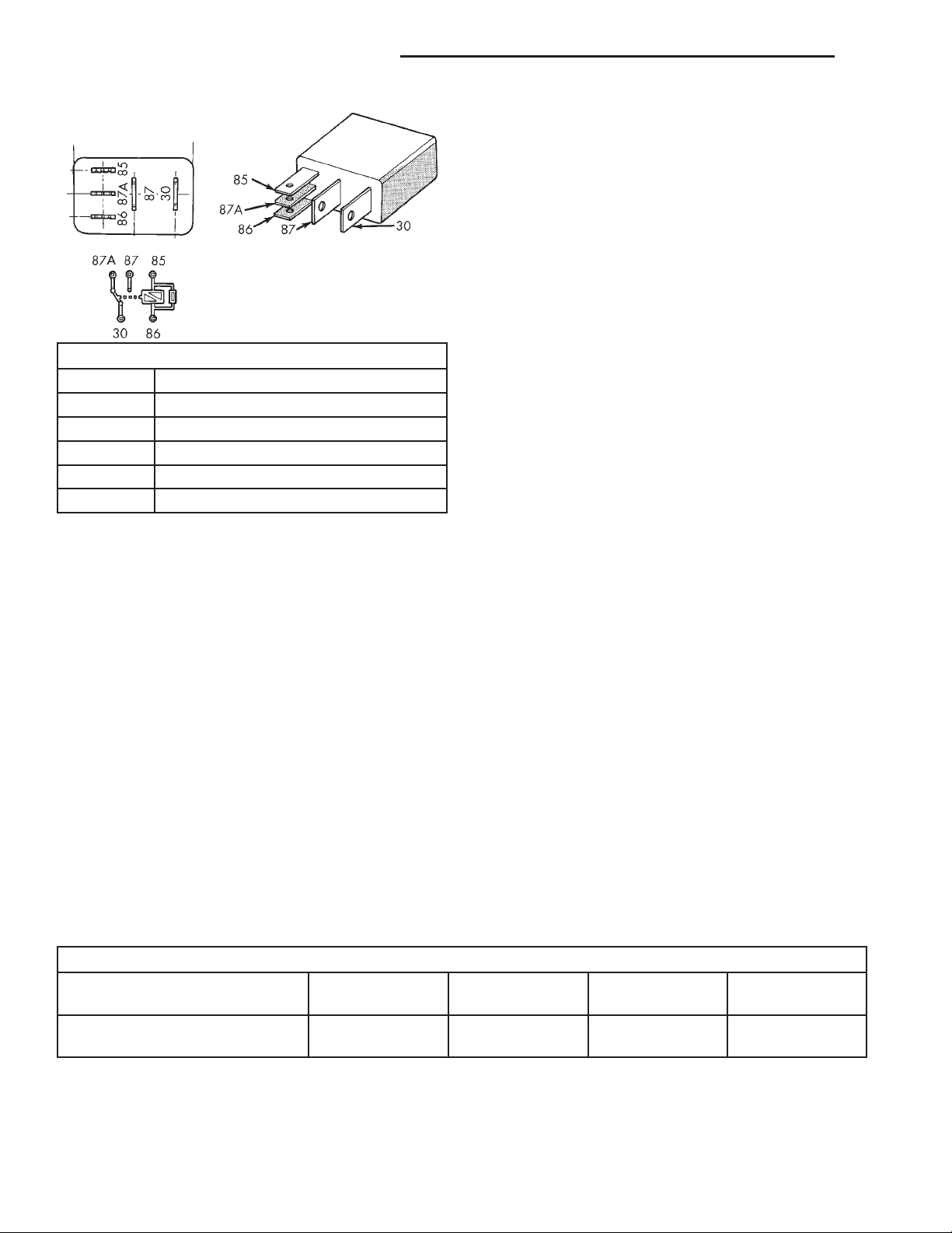
RELAY TEST
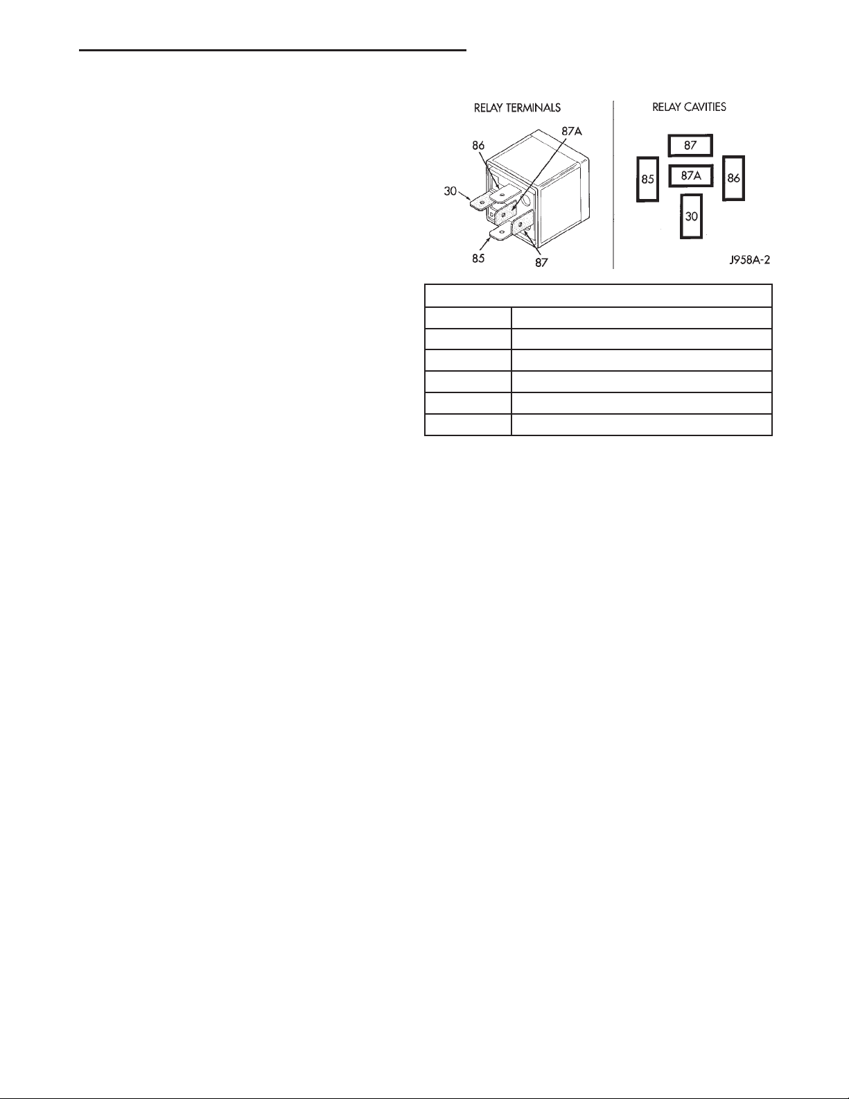
The blower motor relay (Fig. 7) is located in a wire
harness connector that is secured to the heater-A/C
housing behind the glove box on the passenger side
of the vehicle, next to the heater-A/C wire harness
connector in the passenger compartment. Remove the
relay from its connector to perform the following
tests:
(1) A relay in the de-energized position should
have continuity between terminals 87A and 30, and
no continuity between terminals 87 and 30. If OK, go
to Step 2. If not OK, replace the faulty relay.
(2) Resistance between terminals 85 and 86 (electromagnet) should be 75 6 5 ohms. If OK, go to Step
3. If not OK, replace the faulty relay.
(3) Connect a battery to terminals 85 and 86.
There should now be continuity between terminals
30 and 87, and no continuity between terminals 87A
and 30. If OK, see the Relay Circuit Test procedure
in this group. If not OK, replace the faulty relay.
RELAY CIRCUIT TEST
For circuit descriptions and diagrams, refer to
8W-42 - Air Conditioning/Heater in Group 8W - Wiring Diagrams.
NUMBER IDENTIFICATION
30 COMMON FEED
85 COIL GROUND
86 COIL BATTERY
87 NORMALLY OPEN
87A NORMALLY CLOSED
(1) The relay common feed terminal cavity (30) is
connected to fused battery feed directly from a fuse
in the Power Distribution Center (PDC), and should
be hot at all times. Check for battery voltage at the
connector cavity for relay terminal 30. If OK, go to
Step 2. If not OK, repair the open circuit to the PDC
fuse as required.
(2) The relay normally closed terminal cavity (87A)
is not used for this application. Go to Step 3.
(3) The relay normally open terminal cavity (87) is
connected to the blower motor. When the relay is
energized, terminal 87 is connected to terminal 30
and provides full battery current to the blower motor
feed circuit. There should be continuity between the
connector cavity for terminal 87 and the blower
motor relay output circuit cavity of the blower motor
wire harness connector at all times. If OK, go to Step
4. If not OK, repair the open circuit to the blower
motor as required.
(4) The coil battery terminal cavity (86) is connected to the ignition switch. When the ignition
switch is placed in the On position, fused ignition
switch output is directed from a fuse in the junction
block to the relay electromagnetic coil to energize the
relay. There should be battery voltage at the connector cavity for relay terminal 86 with the ignition
switch in the On position. If OK, go to Step 5. If not
OK, repair the open circuit to the junction block fuse
as required.
(5) The coil ground terminal cavity (85) is connected to ground. This terminal supplies the ground
for the relay electromagnet coil. There should be continuity between the connector cavity for relay termi-
TERMINAL LEGEND
Fig. 7 Blower Motor Relay
Page 14

24 - 14 HEATING AND AIR CONDITIONING XJ
DIAGNOSIS AND TESTING (Continued)
nal 85 and a good ground at all times. If not OK,
repair the open circuit as required.
BLOWER MOTOR RESISTOR
For circuit descriptions and diagrams, refer to
8W-42 - Air Conditioning/Heater in Group 8W - Wiring Diagrams.
WARNING: ON VEHICLES EQUIPPED WITH AIRBAGS, REFER TO GROUP 8M - PASSIVE
RESTRAINT SYSTEMS BEFORE ATTEMPTING ANY
STEERING WHEEL, STEERING COLUMN, OR
INSTRUMENT PANEL COMPONENT DIAGNOSIS OR
SERVICE. FAILURE TO TAKE THE PROPER PRECAUTIONS COULD RESULT IN ACCIDENTAL AIRBAG DEPLOYMENT AND POSSIBLE PERSONAL
INJURY.
(1) Disconnect and isolate the battery negative
cable.
(2) Remove the kick cover from the heater-A/C
housing and unplug the wire harness connector from
the blower motor resistor.
(3) Check for continuity between each of the
blower motor switch input terminals of the resistor
and the resistor output terminal. In each case there
should be continuity. If OK, repair the wire harness
circuits between the blower motor switch and the
blower motor resistor or blower motor relay as
required. If not OK, replace the faulty blower motor
resistor.
BLOWER MOTOR SWITCH
For circuit descriptions and diagrams, refer to
8W-42 - Air Conditioning/Heater in Group 8W - Wiring Diagrams.
WARNING: ON VEHICLES EQUIPPED WITH AIRBAGS, REFER TO GROUP 8M - PASSIVE
RESTRAINT SYSTEMS BEFORE ATTEMPTING ANY
STEERING WHEEL, STEERING COLUMN, OR
INSTRUMENT PANEL COMPONENT DIAGNOSIS OR
SERVICE. FAILURE TO TAKE THE PROPER PRECAUTIONS COULD RESULT IN ACCIDENTAL AIRBAG DEPLOYMENT AND POSSIBLE PERSONAL
INJURY.
(1) Check for battery voltage at the fuse in the
Power Distribution Center (PDC). If OK, go to Step
2. If not OK, repair the shorted circuit or component
as required and replace the faulty fuse.
(2) Turn the ignition switch to the Off position.
Disconnect and isolate the battery negative cable.
Remove the heater-A/C control from the instrument
panel. Check for continuity between the ground circuit cavity of the heater-A/C control wire harness
connector and a good ground. There should be conti-
nuity. If OK, go to Step 3. If not OK, repair the open
circuit to ground as required.
(3) With the heater-A/C control wire harness connector unplugged, place the heater-A/C mode control
switch knob in any position except the Off position.
Check for continuity between the ground circuit terminal and each of the blower motor driver circuit terminals of the heater-A/C control as you move the
blower motor switch knob to each of the four speed
positions. There should be continuity at each driver
circuit terminal in only one blower motor switch
speed position. If OK, test and repair the blower
driver circuits between the heater-A/C control connector and the blower motor resistor as required. If
not OK, replace the faulty heater-A/C control unit.
COMPRESSOR
When investigating an air conditioning related
noise, you must first know the conditions under
which the noise occurs. These conditions include:
weather, vehicle speed, transmission in gear or neutral, engine speed, engine temperature, and any
other special conditions. Noises that develop during
air conditioning operation can often be misleading.
For example: What sounds like a failed front bearing
or connecting rod, may be caused by loose bolts, nuts,
mounting brackets, or a loose compressor clutch
assembly.
Drive belts are speed sensitive. At different engine
speeds and depending upon belt tension, belts can
develop noises that are mistaken for a compressor
noise. Improper belt tension can cause a misleading
noise when the compressor clutch is engaged, which
may not occur when the compressor clutch is disengaged. Check the serpentine drive belt condition and
tension as described in Group 7 - Cooling System
before beginning this procedure.
(1) Select a quiet area for testing. Duplicate the
complaint conditions as much as possible. Switch the
compressor on and off several times to clearly identify the compressor noise. Listen to the compressor
while the clutch is engaged and disengaged. Probe
the compressor with an engine stethoscope or a long
screwdriver with the handle held to your ear to better localize the source of the noise.
(2) Loosen all of the compressor mounting hardware and retighten. Tighten the compressor clutch
mounting nut. Be certain that the clutch coil is
mounted securely to the compressor, and that the
clutch plate and pulley are properly aligned and have
the correct air gap. See Compressor and Compressor
Clutch in the Removal and Installation section of this
group for the procedures.
(3) To duplicate a high-ambient temperature condition (high head pressure), restrict the air flow
through the condenser. Install a manifold gauge set
Page 15

XJ HEATING AND AIR CONDITIONING 24 - 15
DIAGNOSIS AND TESTING (Continued)
to be certain that the discharge pressure does not
exceed 2760 kPa (400 psi).
(4) Check the refrigerant system plumbing for
incorrect routing, rubbing or interference, which can
cause unusual noises. Also check the refrigerant lines
for kinks or sharp bends that will restrict refrigerant
flow, which can cause noises. See Suction and Discharge Line in the Removal and Installation section
of this group for more information.
(5) If the noise is from opening and closing of the
high pressure relief valve, evacuate and recharge the
refrigerant system. See Refrigerant System Evacuate
and Refrigerant System Charge in the Service Procedures section of this group. If the high pressure relief
valve still does not seat properly, replace the compressor.
(6) If the noise is from liquid slugging on the suction line, replace the accumulator. See Accumulator
in the Removal and Installation section of this group
for the procedures. Check the refrigerant oil level
and the refrigerant system charge. See Refrigerant
Oil Level and Refrigerant System Charge in the Service Procedures section of this group. If the liquid
slugging condition continues following accumulator
replacement, replace the compressor.
(7) If the noise continues, replace the compressor
and repeat Step 1.
COMPRESSOR CLUTCH COIL
For circuit descriptions and diagrams, refer to
8W-42 - Air Conditioning/Heater in Group 8W - Wiring Diagrams. The battery must be fully-charged
before performing the following tests. Refer to Group
8A - Battery for more information.
(1) Connect an ammeter (0 to 10 ampere scale) in
series with the clutch coil terminal. Use a voltmeter
(0 to 20 volt scale) with clip-type leads for measuring
the voltage across the battery and the compressor
clutch coil.
(2) With the heater-A/C mode control switch in any
A/C mode, and the blower motor switch in the lowest
speed position, start the engine and run it at normal
idle.
(3) The compressor clutch coil voltage should read
within two volts of the battery voltage. If there is
voltage at the clutch coil, but the reading is not
within two volts of the battery voltage, test the
clutch coil feed circuit for excessive voltage drop and
repair as required. If there is no voltage reading at
the clutch coil, use a DRB scan tool and the proper
Diagnostic Procedures manual for testing of the compressor clutch circuit. The following components
must be checked and repaired as required before you
can complete testing of the clutch coil:
• Fuses in the junction block and the Power Dis-
tribution Center (PDC)
• Heater-A/C mode control switch
• Compressor clutch relay
• High pressure cut-off switch
• Low pressure cycling clutch switch
• Powertrain Control Module (PCM).
(4) The compressor clutch coil is acceptable if the
current draw measured at the clutch coil is 2.0 to 3.9
amperes with the electrical system voltage at 11.5 to
12.5 volts. This should only be checked with the work
area temperature at 21° C (70° F). If system voltage
is more than 12.5 volts, add electrical loads by turning on electrical accessories until the system voltage
drops below 12.5 volts.
(a) If the clutch coil current reading is four
amperes or more, the coil is shorted and should be
replaced.
(b) If the clutch coil current reading is zero, the
coil is open and should be replaced.
COMPRESSOR CLUTCH RELAY
RELAY TEST
The compressor clutch relay (Fig. 8) is located in
the Power Distribution Center (PDC). Refer to the
PDC label for relay identification and location.
Remove the relay from the PDC to perform the following tests:
(1) A relay in the de-energized position should
have continuity between terminals 87A and 30, and
no continuity between terminals 87 and 30. If OK, go
to Step 2. If not OK, replace the faulty relay.
(2) Resistance between terminals 85 and 86 (elec-
tromagnet) should be 75 6 5 ohms. If OK, go to Step
3. If not OK, replace the faulty relay.
(3) Connect a battery to terminals 85 and 86.
There should now be continuity between terminals
30 and 87, and no continuity between terminals 87A
and 30. If OK, see Relay Circuit Test in the Diagnosis and Testing section of this group. If not OK,
replace the faulty relay.
RELAY CIRCUIT TEST
For circuit descriptions and diagrams, refer to
8W-42 - Air Conditioning/Heater in Group 8W - Wiring Diagrams.
(1) The relay common feed terminal cavity (30) is
connected to fused battery feed. There should be battery voltage at the cavity for relay terminal 30 at all
times. If OK, go to Step 2. If not OK, repair the open
circuit to the fuse in the PDC as required.
(2) The relay normally closed terminal (87A) is not
used in this application. Go to Step 3.
(3) The relay normally open terminal cavity (87) is
connected to the compressor clutch coil. There should
be continuity between this cavity and the A/C compressor clutch relay output circuit cavity of the com-
Page 16
24 - 16 HEATING AND AIR CONDITIONING XJ
DIAGNOSIS AND TESTING (Continued)
DUAL FUNCTION HIGH PRESSURE SWITCH/ HIGH PRESSURE CUT-OFF SWITCH
Before performing diagnosis of the dual function
high pressure switch, or the high pressure cut-off
switch, verify that the refrigerant system has the correct refrigerant charge. See Refrigerant System
Charge in the Service Procedures section of this
group for more information.
For circuit descriptions and diagrams, refer to
8W-42 - Air Conditioning/Heater in Group 8W - Wiring Diagrams.
(1) Disconnect and isolate the battery negative
TERMINAL LEGEND
NUMBER IDENTIFICATION
30 COMMON FEED
85 COIL GROUND
86 COIL BATTERY
87 NORMALLY OPEN
87A NORMALLY CLOSED
Fig. 8 Compressor Clutch Relay
pressor clutch coil wire harness connector. If OK, go
to Step 4. If not OK, repair the open circuit as
required.
(4) The relay coil battery terminal (86) is connected to the fused ignition switch output (run/start)
circuit. There should be battery voltage at the cavity
for relay terminal 86 with the ignition switch in the
On position. If OK, go to Step 5. If not OK, repair the
open circuit to the fuse in the junction block as
required.
(5) The coil ground terminal cavity (85) is switched
to ground through the Powertrain Control Module
(PCM). There should be continuity between this cavity and the A/C compressor clutch relay control circuit cavity of the PCM wire harness connector C
(gray) at all times. If not OK, repair the open circuit
as required.
cable.
(2) Unplug the high pressure switch wire harness
connector from the switch on the refrigerant system
fitting.
(3) On the dual function high pressure switch,
check for continuity between terminals C and D. On
the two terminal switch, check for continuity
between both terminals of the high pressure cut-off
switch. There should be continuity. If OK, test and
repair the A/C switch sense circuit as required. If not
OK, replace the faulty switch.
HEATER PERFORMANCE
Before performing the following tests, refer to
Group 7 - Cooling System for the procedures to check
the radiator coolant level, serpentine drive belt tension, radiator air flow and the radiator fan operation.
Also be certain that the accessory vacuum supply
line is connected at the engine intake manifold.
MAXIMUM HEATER OUTPUT
Engine coolant is delivered to the heater core
through two heater hoses. With the engine idling at
normal operating temperature, set the temperature
control knob in the full hot position, the mode control
switch knob in the floor heat position, and the blower
motor switch knob in the highest speed position.
Using a test thermometer, check the temperature of
the air being discharged at the heater-A/C housing
floor outlets. Compare the test thermometer reading
to the Temperature Reference chart.
Ambient Air Temperature
Minimum Air Temperature at
Floor Outlet
Temperature Reference
15.5° C
(60° F)
62.2° C
(144° F)
21.1° C
(70° F)
63.8° C
(147° F)
26.6° C
(80° F)
65.5° C
(150° F)
32.2° C
(90° F)
67.2° C
(153° F)
Page 17

XJ HEATING AND AIR CONDITIONING 24 - 17
DIAGNOSIS AND TESTING (Continued)
If the floor outlet air temperature is too low, refer
to Group 7 - Cooling System to check the engine coolant temperature specifications. Both of the heater
hoses should be hot to the touch. The coolant return
heater hose should be slightly cooler than the coolant
supply heater hose. If the return hose is much cooler
than the supply hose, locate and repair the engine
coolant flow obstruction in the cooling system. Refer
to Group 7 - Cooling System for the procedures.
OBSTRUCTED COOLANT FLOW Possible locations or causes of obstructed coolant flow:
• Pinched or kinked heater hoses.
• Improper heater hose routing.
• Plugged heater hoses or supply and return ports
at the cooling system connections.
• A plugged heater core.
If proper coolant flow through the cooling system is
verified, and heater outlet air temperature is still
low, a mechanical problem may exist.
MECHANICAL PROBLEMS Possible locations or
causes of insufficient heat:
• An obstructed cowl air intake.
• Obstructed heater system outlets.
• A blend-air door not functioning properly.
(2) Unplug the low pressure cycling clutch switch
wire harness connector from the switch on the accumulator fitting.
(3) Install a jumper wire between the two cavities
of the low pressure cycling clutch switch wire harness connector.
(4) Connect a manifold gauge set to the refrigerant
system service ports. See Refrigerant System Service
Equipment and Refrigerant System Service Ports in
the Description and Operation section of this group
for more information.
(5) Connect the battery negative cable.
(6) Place the heater-A/C mode control switch knob
in any A/C position and start the engine.
(7) Check for continuity between the two terminals
of the low pressure cycling clutch switch. There
should be continuity with a suction pressure reading
of 262 kPa (38 psi) or above, and no continuity with a
suction pressure reading of 141 kPa (20.5 psi) or
below. If OK, test and repair the A/C switch sense
circuit as required. If not OK, replace the faulty
switch.
REFRIGERANT SYSTEM LEAKS
TEMPERATURE CONTROL
If the heater outlet air temperature cannot be
adjusted with the temperature control knob on the
heater-A/C control panel, the following could require
service:
• The heater-A/C control.
• The temperature control motor.
• The blend-air door.
• Improper engine coolant temperature.
LOW PRESSURE CYCLING CLUTCH SWITCH
Before performing diagnosis of the low pressure
cycling clutch switch, be certain that the switch is
properly installed on the accumulator fitting. If the
switch is too loose it may not open the Schrader-type
valve in the accumulator fitting, which will prevent
the switch from correctly monitoring the refrigerant
system pressure. Remember that lower ambient temperatures, below about -1° C (30° F), during cold
weather will open the switch contacts and prevent
compressor operation due to the pressure/temperature relationship of the refrigerant.
Also verify that the refrigerant system has the correct refrigerant charge. See Refrigerant System
Charge in the Service Procedures section of this
group for more information.
For circuit descriptions and diagrams, refer to
8W-42 - Air Conditioning/Heater in Group 8W - Wiring Diagrams.
(1) Disconnect and isolate the battery negative
cable.
WARNING: REVIEW THE WARNINGS AND CAUTIONS IN THE FRONT OF THIS GROUP BEFORE
LEAK TESTING THE SYSTEM.
If the air conditioning system is not cooling properly, determine if the refrigerant system is fullycharged. See A/C Performance in this group for the
procedures. If the refrigerant system is low or empty;
a leak at a refrigerant line, connector fitting, component, or component seal is likely.
An electronic leak detector designed for R-134a
refrigerant, or a fluorescent R-134a leak detection
dye and a black light are recommended for locating
and confirming refrigerant system leaks. Refer to the
operating instructions supplied by the equipment
manufacturer for proper care and use of this equipment.
An oily residue on or near refrigerant system lines,
connector fittings, components, or component seals
can indicate the general location of a possible refrigerant leak. However, the exact leak location should
be confirmed with an electronic leak detector prior to
component repair or replacement.
To detect a leak in the refrigerant system with an
electronic leak detector, perform one of the following
procedures:
SYSTEM EMPTY
(1) Evacuate the refrigerant system. See Refrigerant System Evacuate in this group for the procedures.
Page 18
24 - 18 HEATING AND AIR CONDITIONING XJ
DIAGNOSIS AND TESTING (Continued)
(2) Connect and dispense 0.283 kilograms (0.625
pounds or 10 ounces) of R-134a refrigerant into the
evacuated refrigerant system. See Refrigerant System Charge in this group for the procedures.
(3) Position the vehicle in a wind-free work area.
This will aid in detecting small leaks.
(4) With the engine not running, use a electronic
R-134a leak detector and search for leaks. Because
R-134a refrigerant is heavier than air, the leak detector probe should be moved slowly along the bottom
side of all refrigerant lines, connector fittings and
components.
(5) To inspect the evaporator coil for leaks, insert
the electronic leak detector probe into the center
instrument panel outlet. Set the blower motor switch
to the lowest speed position, and the mode control
switch in the recirculation mode.
SYSTEM LOW
(1) Position the vehicle in a wind-free work area.
This will aid in detecting small leaks.
(2) Bring the refrigerant system up to operating
temperature and pressure. This is done by allowing
the engine to run with the air conditioning system
turned on for five minutes.
(3) With the engine not running, use a electronic
R-134a leak detector and search for leaks. Because
R-134a refrigerant is heavier than air, the leak detector probe should be moved slowly along the bottom
side of all refrigerant lines, connector fittings and
components.
(4) To inspect the evaporator coil for leaks, insert
the electronic leak detector probe into the center
instrument panel outlet. Set the blower motor switch
to the lowest speed position, and the mode control
switch in the recirculation mode.
VACUUM SYSTEM
Vacuum control is used to operate the mode doors
in the heater-only and heater-A/C housings. Testing
of the heater-only and heater-A/C mode control
switch operation will determine if the vacuum, electrical, and mechanical controls are functioning. However, it is possible that a vacuum control system that
operates perfectly at engine idle (high engine vacuum) may not function properly at high engine
speeds or loads (low engine vacuum). This can be
caused by leaks in the vacuum system, or a faulty
vacuum check valve.
A vacuum system test will help to identify the
source of poor vacuum system performance or vacuum system leaks. Before starting this test, stop the
engine and make certain that the problem is not a
disconnected vacuum supply tube at the engine
intake manifold vacuum tap or at the vacuum reservoir.
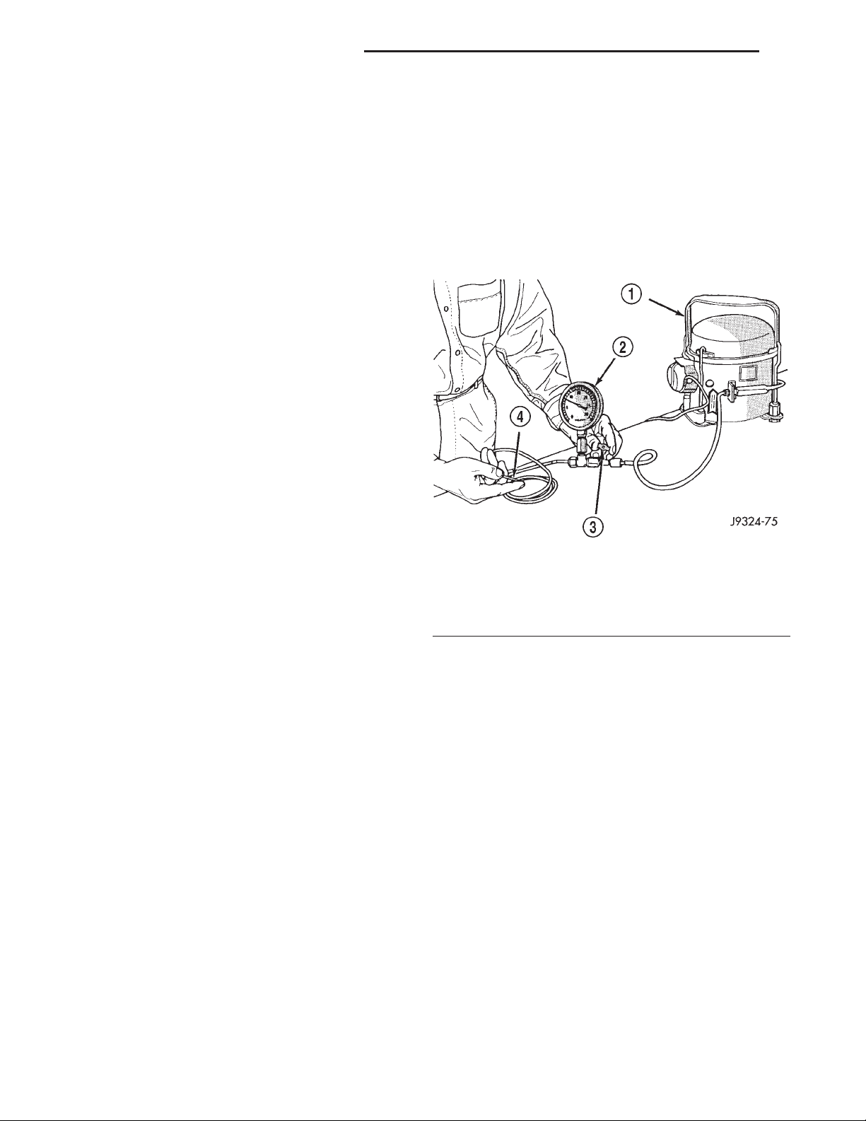
Use an adjustable vacuum test set (Special Tool
C-3707-B) and a suitable vacuum pump to test the
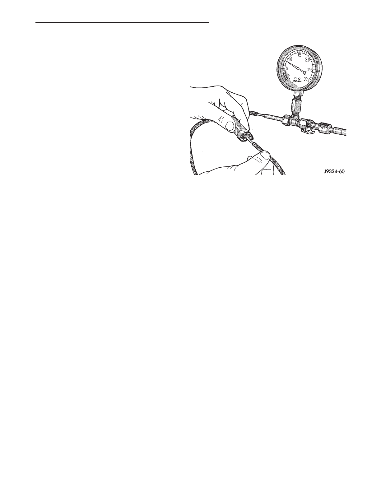
heater-A/C vacuum control system. With a finger
placed over the end of the vacuum test hose probe
(Fig. 9), adjust the bleed valve on the test set gauge
to obtain a vacuum of exactly 27 kPa (8 in. Hg.).
Release and block the end of the probe several times
to verify that the vacuum reading returns to the
exact 27 kPa (8 in. Hg.) setting. Otherwise, a false
reading will be obtained during testing.
Fig. 9 Adjust Vacuum Test Bleed Valve
1 – VACUUM PUMP TOOL C-4289
2 – VACUUM TEST SET C-3707
3 – BLEED VALVE
4 – PROBE
VACUUM CHECK VALVE
(1) Remove the vacuum check valve. The valve is
located in the vacuum supply tube (black) at the
heater-A/C system vacuum tee.
(2) Connect the test set vacuum supply hose to the
heater-A/C control side of the valve. When connected
to this side of the check valve, no vacuum should
pass and the test set gauge should return to the 27
kPa (8 in. Hg.) setting. If OK, go to Step 3. If not OK,
replace the faulty valve.
(3) Connect the test set vacuum supply hose to the
engine vacuum side of the valve. When connected to
this side of the check valve, vacuum should flow
through the valve without restriction. If not OK,
replace the faulty valve.
HEATER-A/C CONTROLS
(1) Connect the test set vacuum probe to the heater-A/C vacuum supply (black) tube at the tee in the
engine compartment. Position the test set gauge so
that it can be viewed from the passenger compartment.
Page 19
XJ HEATING AND AIR CONDITIONING 24 - 19
DIAGNOSIS AND TESTING (Continued)
(2) Place the heater-A/C mode control switch knob
in each mode position, one position at a time, and
pause after each selection. The test set gauge should
return to the 27 kPa (8 in. Hg.) setting shortly after
each selection is made. If not OK, a component or
vacuum line in the vacuum circuit of the selected
mode has a leak. See the procedure in Locating Vacuum Leaks.
CAUTION: Do not use lubricant on the switch ports
or in the holes in the plug, as lubricant will ruin the
vacuum valve in the switch. A drop of clean water
in the connector plug holes will help the connector
slide onto the switch ports.
LOCATING VACUUM LEAKS
WARNING: ON VEHICLES EQUIPPED WITH AIRBAGS, REFER TO GROUP 8M - PASSIVE
RESTRAINT SYSTEMS BEFORE ATTEMPTING ANY
STEERING WHEEL, STEERING COLUMN, OR
INSTRUMENT PANEL COMPONENT DIAGNOSIS OR
SERVICE. FAILURE TO TAKE THE PROPER PRECAUTIONS COULD RESULT IN ACCIDENTAL AIRBAG DEPLOYMENT AND POSSIBLE PERSONAL
INJURY.
gauge. The vacuum reading will fluctuate when your
fingers contact the source of the leak. To repair the
vacuum line, cut out the leaking section of the line.
Then, insert the loose ends of the line into a suitable
length of 3 millimeter (0.125 inch) inside diameter
rubber hose.
Fig. 10 Vacuum Circuit Test
(1) Disconnect the vacuum harness connector
behind the glove box and inboard of the glove box
opening on the heater-A/C housing.
(2) Connect the test set vacuum hose probe to each
port in the heater-A/C housing half of the vacuum
harness connector, one port at a time, and pause
after each connection (Fig. 10). The test set gauge
should return to the 27 kPa (8 in. Hg.) setting
shortly after each connection is made. If OK, replace
the faulty heater-A/C control. If not OK, go to Step 3.
(3) Determine the vacuum line color of the vacuum
circuit that is leaking. To determine the vacuum line
colors, refer to the Vacuum Circuits chart (Fig. 11) or
(Fig. 12).
(4) Disconnect and plug the vacuum line from the
component (fitting, actuator, valve, switch, or reservoir) on the other end of the leaking circuit. Instrument panel disassembly or removal may be necessary
to gain access to some components. See the service
procedures in this group.
(5) Connect the test set hose or probe to the open
end of the leaking circuit. The test set gauge should
return to the 27 kPa (8 in. Hg.) setting shortly after
each connection is made. If OK, replace the faulty
disconnected component. If not OK, go to Step 6.
(6) To locate a leak in a vacuum line, leave one
end of the line plugged and connect the test set hose
or probe to the other end of the line. Run your fingers slowly along the line while watching the test set
SERVICE PROCEDURES
REFRIGERANT OIL LEVEL
When an air conditioning system is assembled at
the factory, all components except the compressor are
refrigerant oil free. After the refrigerant system has
been charged and operated, the refrigerant oil in the
compressor is dispersed throughout the refrigerant
system. The accumulator, evaporator, condenser, and
compressor will each retain a significant amount of
the needed refrigerant oil.
It is important to have the correct amount of oil in
the refrigerant system. This ensures proper lubrication of the compressor. Too little oil will result in
damage to the compressor. Too much oil will reduce
the cooling capacity of the air conditioning system.
It will not be necessary to check the oil level in the
compressor or to add oil, unless there has been an oil
loss. An oil loss may occur due to a rupture or leak
from a refrigerant line, a connector fitting, a component, or a component seal. If a leak occurs, add 30
milliliters (1 fluid ounce) of refrigerant oil to the
refrigerant system after the repair has been made.
Refrigerant oil loss will be evident at the leak point
by the presence of a wet, shiny surface around the
leak.
Refrigerant oil must be added when a accumulator,
evaporator coil, or condenser are replaced. See the
Refrigerant Oil Capacities chart. When a compressor
Page 20
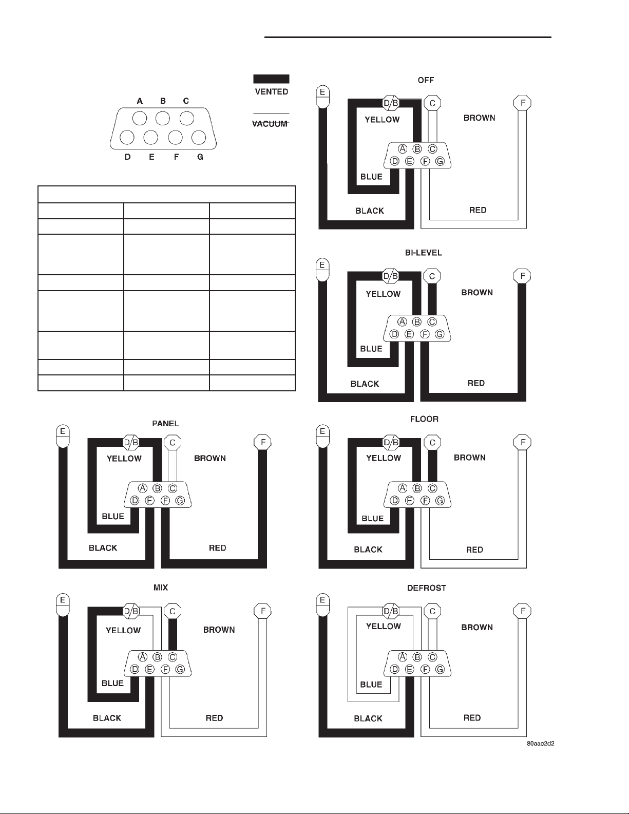
24 - 20 HEATING AND AIR CONDITIONING XJ
SERVICE PROCEDURES (Continued)
VACUUM CIRCUIT LEGEND
I. D. Function Color
A Not Used N/A
B Defrost
Actuator (Full
Position)
C Floor Actuator Brown
D Defrost
Actuator
(Mid-Position)
E Vacuum Supply
(Reservoir)
F Panel Actuator Red
G Not Used N/A
Yellow
Blue
Black
Fig. 11 Vacuum Circuits - Heater Only
Page 21
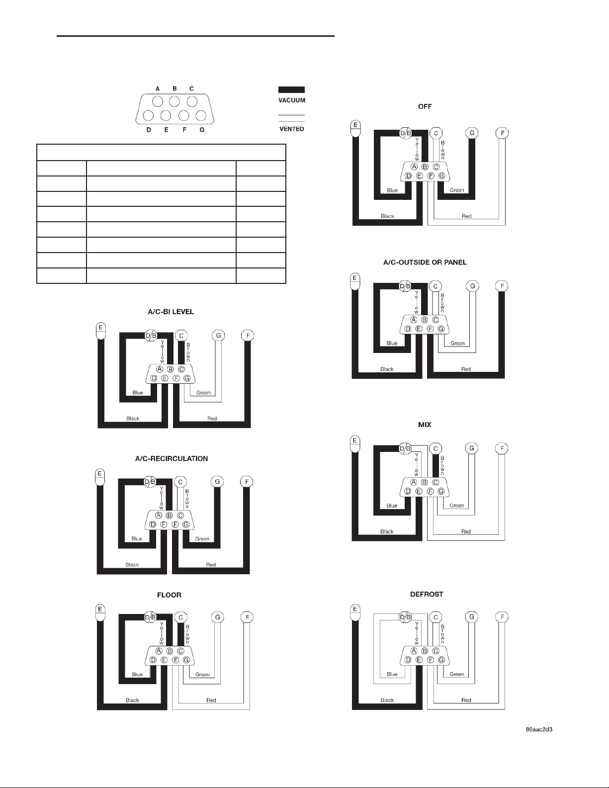
XJ HEATING AND AIR CONDITIONING 24 - 21
SERVICE PROCEDURES (Continued)
VACUUM CIRCUIT LEGEND
I. D. Function Color
A Not Used N/A
B Defrost Actuator (Full Position) Yellow
C Floor Actuator Brown
D Defrost Actuator (Mid-Position) Blue
E Vacuum Supply (Reservoir) Black
F Panel Actuator Red
G Recirculation Actuator Green
Fig. 12 Vacuum Circuits - Heater-A/C
Page 22
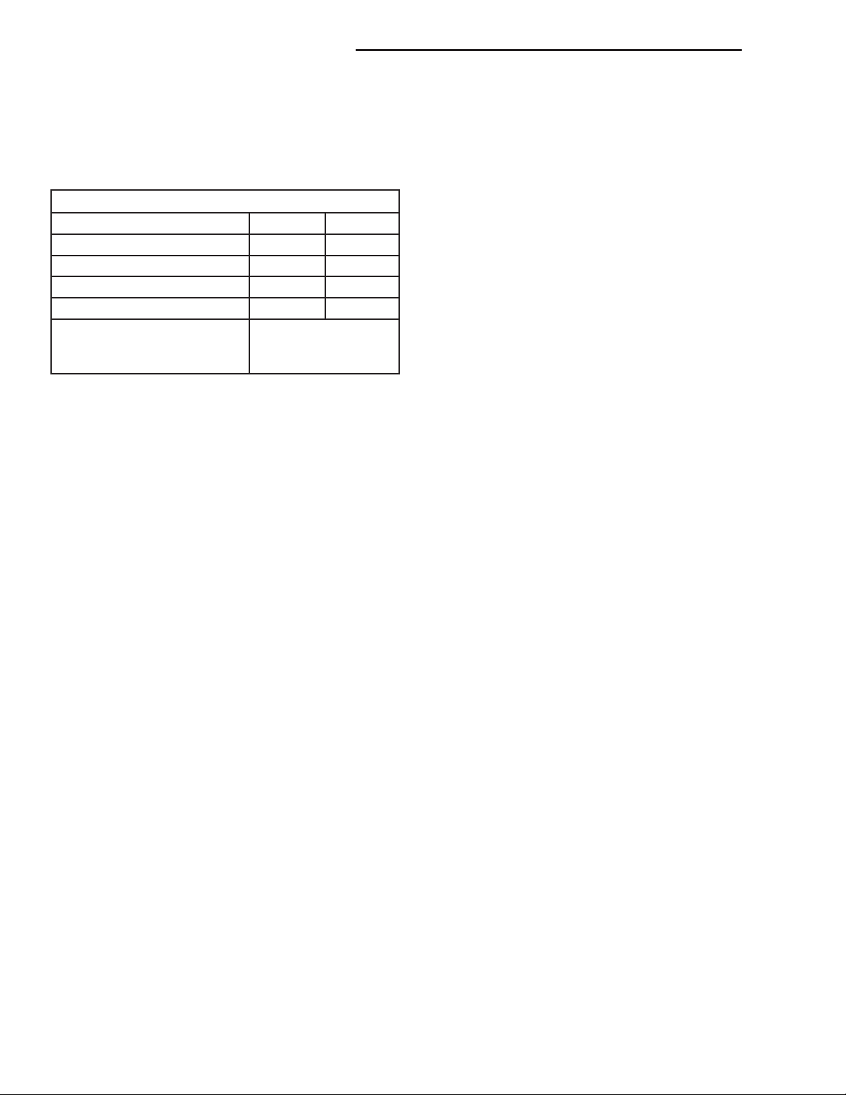
24 - 22 HEATING AND AIR CONDITIONING XJ
SERVICE PROCEDURES (Continued)
is replaced, the refrigerant oil must be drained from
the old compressor and measured. Drain all of the
refrigerant oil from the new compressor, then fill the
new compressor with the same amount of refrigerant
oil that was drained out of the old compressor.
Refrigerant Oil Capacities
Component ml fl oz
A/C System 180 6.1
Accumulator 90 3
Condenser 22 .75
Evaporator 45 1.5
drain and measure
Compressor
the oil from the old
compressor as noted
REFRIGERANT RECOVERY
WARNING: REVIEW THE WARNINGS AND CAUTIONS IN THE GENERAL INFORMATION SECTION
NEAR THE FRONT OF THIS GROUP BEFORE
RECOVERING REFRIGERANT.
A R-134a refrigerant recovery/recycling/charging
station that meets SAE Standard J2210 must be
used to recover the refrigerant from an R-134a refrigerant system. Refer to the operating instructions supplied by the equipment manufacturer for the proper
care and use of this equipment.
REFRIGERANT SYSTEM EVACUATE
WARNING: REVIEW THE WARNINGS AND CAUTIONS IN THE GENERAL INFORMATION SECTION
NEAR THE FRONT OF THIS GROUP BEFORE EVACUATING THE SYSTEM.
If the refrigerant system has been open to the
atmosphere, it must be evacuated before the system
can be charged. If moisture and air enters the system
and becomes mixed with the refrigerant, the compressor head pressure will rise above acceptable
operating levels. This will reduce the performance of
the air conditioner and damage the compressor.
Evacuating the refrigerant system will remove the
air and boil the moisture out of the system at near
room temperature. To evacuate the refrigerant system, use the following procedure:
(1) Connect a R-134a refrigerant recovery/recycling/charging station that meets SAE Standard
J2210 and a manifold gauge set to the refrigerant
system of the vehicle.
(2) Open the low and high side valves and start
the charging station vacuum pump. When the suction gauge reads 88 kPa (26 in. Hg.) vacuum or
greater, close all of the valves and turn off the vacuum pump.
(a) If the refrigerant system fails to reach the
specified vacuum, the system has a leak that must
be corrected. See Refrigerant System Leaks in the
Diagnosis and Testing section of this group for the
procedures.
(b) If the refrigerant system maintains the specified vacuum for five minutes, restart the vacuum
pump, open the suction and discharge valves and
evacuate the system for an additional ten minutes.
(3) Close all of the valves, and turn off the charg-
ing station vacuum pump.
(4) The refrigerant system is now ready to be
charged with R-134a refrigerant. See Refrigerant
System Charge in the Service Procedures section of
this group.
REFRIGERANT SYSTEM CHARGE
WARNING: REVIEW THE WARNINGS AND CAUTIONS IN THE FRONT OF THIS GROUP BEFORE
CHARGING THE REFRIGERANT SYSTEM.
After the refrigerant system has been tested for
leaks and evacuated, a refrigerant charge can be
injected into the system. See Refrigerant Charge
Capacity for the proper amount of the refrigerant
charge.
A R-134a refrigerant recovery/recycling/charging
station that meets SAE Standard J2210 must be
used to charge the refrigerant system with R-134a
refrigerant. Refer to the operating instructions supplied by the equipment manufacturer for proper care
and use of this equipment.
REFRIGERANT CHARGE CAPACITY
The R-134a refrigerant system charge capacity for
this vehicle is 0.567 kilograms (1.25 pounds).
REFRIGERANT SYSTEM SERVICE EQUIPMENT
WARNING: EYE PROTECTION MUST BE WORN
WHEN SERVICING AN AIR CONDITIONING REFRIGERANT SYSTEM. TURN OFF (ROTATE CLOCKWISE)
ALL VALVES ON THE EQUIPMENT BEING USED,
BEFORE CONNECTING TO OR DISCONNECTING
FROM THE REFRIGERANT SYSTEM. FAILURE TO
OBSERVE THESE WARNINGS MAY RESULT IN PERSONAL INJURY.
When servicing the air conditioning system, a
R-134a refrigerant recovery/recycling/charging station that meets SAE Standard J2210 must be used.
Contact an automotive service equipment supplier for
refrigerant recovery/recycling/charging equipment.
Refer to the operating instructions supplied by the
Page 23
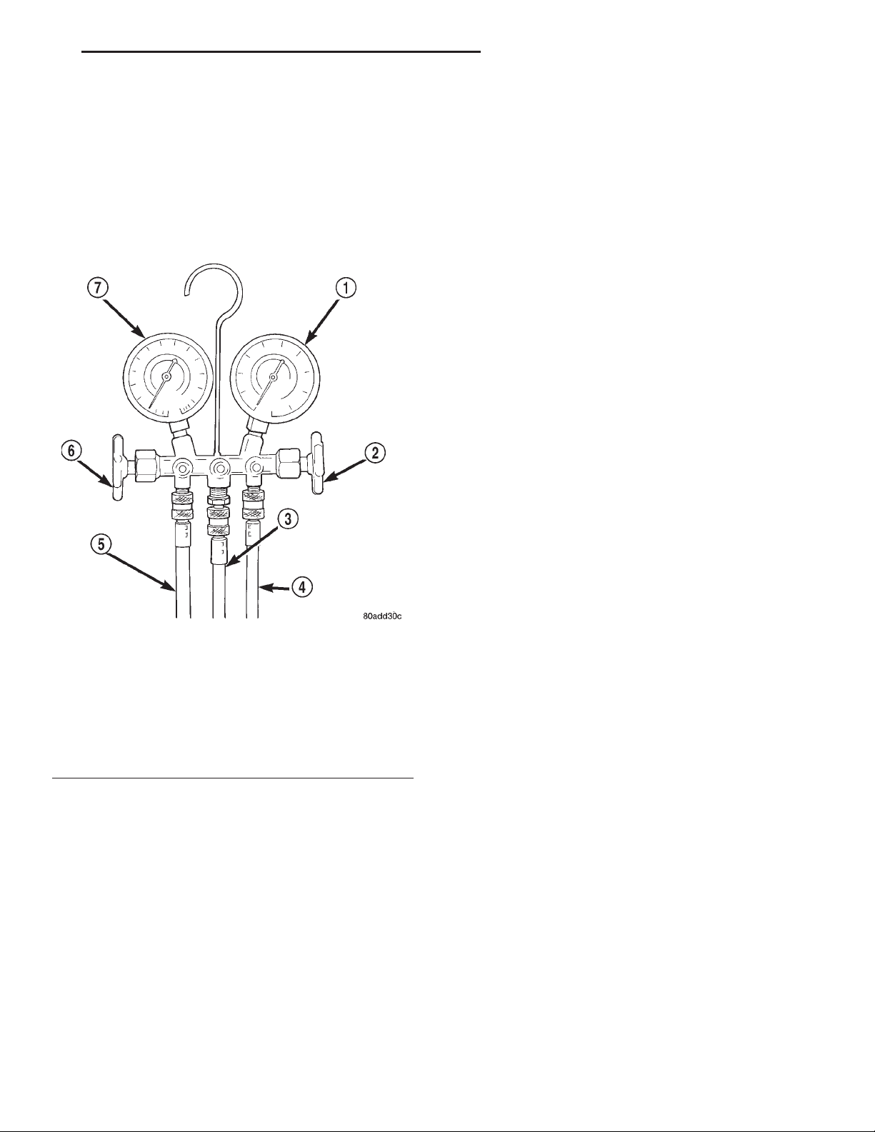
XJ HEATING AND AIR CONDITIONING 24 - 23
SERVICE PROCEDURES (Continued)
equipment manufacturer for proper care and use of
this equipment.
A manifold gauge set may be needed with some
recovery/recycling/charging equipment (Fig. 13). The
service hoses on the gauge set being used should
have manual (turn wheel), or automatic back-flow
valves at the service port connector ends. This will
prevent refrigerant from being released into the
atmosphere.
Fig. 13 Manifold Gauge Set - Typical
1 – HIGH PRESSURE GAUGE
2 – VALVE
3 – VACUUM/REFRIGERANT HOSE (YELLOW W/BLACK
STRIPE)
4 – HIGH PRESSURE HOSE (RED W/BLACK STRIPE)
5 – LOW PRESSURE HOSE (BLUE W/BLACK STRIPE)
6 – VALVE
7 – LOW PRESSURE GAUGE
MANIFOLD GAUGE SET CONNECTIONS
CAUTION: Do not use an R-12 manifold gauge set
on an R-134a system. The refrigerants are not compatible and system damage will result.
LOW PRESSURE GAUGE HOSE The low pressure
hose (Blue with Black stripe) attaches to the suction
service port. This port is located on the suction line
between the accumulator outlet and the compressor.
HIGH PRESSURE GAUGE HOSE The high pressure hose (Red with Black stripe) attaches to the discharge service port. This port is located on the
discharge line between the compressor and the condenser inlet.
RECOVERY/RECYCLING/EVACUATION/CHARGING HOSE The center manifold hose (Yellow, or
White, with Black stripe) is used to recover, evacuate, and charge the refrigerant system. When the low
or high pressure valves on the manifold gauge set
are opened, the refrigerant in the system will escape
through this hose.
REMOVAL AND INSTALLATION
SERVICE WARNINGS AND PRECAUTIONS
WARNING:
• THE AIR CONDITIONING SYSTEM CONTAINS
REFRIGERANT UNDER HIGH PRESSURE. SEVERE
PERSONAL INJURY MAY RESULT FROM IMPROPER
SERVICE PROCEDURES. REPAIRS SHOULD ONLY
BE PERFORMED BY QUALIFIED SERVICE PERSONNEL.
• AVOID BREATHING THE REFRIGERANT AND
REFRIGERANT OIL VAPOR OR MIST. EXPOSURE
MAY IRRITATE THE EYES, NOSE, AND/OR THROAT.
WEAR EYE PROTECTION WHEN SERVICING THE
AIR CONDITIONING REFRIGERANT SYSTEM. SERIOUS EYE INJURY CAN RESULT FROM DIRECT
CONTACT WITH THE REFRIGERANT. IF EYE CONTACT OCCURS, SEEK MEDICAL ATTENTION IMMEDIATELY.
• DO NOT EXPOSE THE REFRIGERANT TO
OPEN FLAME. POISONOUS GAS IS CREATED
WHEN REFRIGERANT IS BURNED. AN ELECTRONIC LEAK DETECTOR IS RECOMMENDED.
• IF ACCIDENTAL SYSTEM DISCHARGE
OCCURS, VENTILATE THE WORK AREA BEFORE
RESUMING SERVICE. LARGE AMOUNTS OF
REFRIGERANT RELEASED IN A CLOSED WORK
AREA WILL DISPLACE THE OXYGEN AND CAUSE
SUFFOCATION.
• THE EVAPORATION RATE OF R-134a REFRIGERANT AT AVERAGE TEMPERATURE AND ALTITUDE IS EXTREMELY HIGH. AS A RESULT,
ANYTHING THAT COMES IN CONTACT WITH THE
REFRIGERANT WILL FREEZE. ALWAYS PROTECT
THE SKIN OR DELICATE OBJECTS FROM DIRECT
CONTACT WITH THE REFRIGERANT.
• THE R-134a SERVICE EQUIPMENT OR THE
VEHICLE REFRIGERANT SYSTEM SHOULD NOT BE
PRESSURE TESTED OR LEAK TESTED WITH COMPRESSED AIR. SOME MIXTURES OF AIR AND
R-134a HAVE BEEN SHOWN TO BE COMBUSTIBLE
AT ELEVATED PRESSURES. THESE MIXTURES ARE
POTENTIALLY DANGEROUS, AND MAY RESULT IN
FIRE OR EXPLOSION CAUSING INJURY OR PROPERTY DAMAGE.
Page 24

24 - 24 HEATING AND AIR CONDITIONING XJ
REMOVAL AND INSTALLATION (Continued)
CAUTION:
• Liquid refrigerant is corrosive to metal surfaces. Follow the operating instructions supplied
with the service equipment being used.
• Never add R-12 to a refrigerant system
designed to use R-134a. Damage to the system will
result.
• R-12 refrigerant oil must not be mixed with
R-134a refrigerant oil. They are not compatible.
• Do not use R-12 equipment or parts on the
R-134a system. Damage to the system will result.
• Do not overcharge the refrigerant system. This
will cause excessive compressor head pressure
and can cause noise and system failure.
• Recover the refrigerant before opening any fitting or connection. Open the fittings with caution,
even after the system has been discharged. Never
open or loosen a connection before recovering the
refrigerant.
• Do not remove the secondary retention clip
from any spring-lock coupler connection while the
refrigerant system is under pressure. Recover the
refrigerant before removing the secondary retention
clip. Open the fittings with caution, even after the
system has been discharged. Never open or loosen
a connection before recovering the refrigerant.
• The refrigerant system must always be evacuated before charging.
• Do not open the refrigerant system or uncap a
replacement component until you are ready to service the system. This will prevent contamination in
the system.
• Before disconnecting a component, clean the
outside of the fittings thoroughly to prevent contamination from entering the refrigerant system.
• Immediately after disconnecting a component
from the refrigerant system, seal the open fittings
with a cap or plug.
• Before connecting an open refrigerant fitting,
always install a new seal or gasket. Coat the fitting
and seal with clean refrigerant oil before connecting.
• Do not remove the sealing caps from a replacement component until it is to be installed.
• When installing a refrigerant line, avoid sharp
bends that may restrict refrigerant flow. Position the
refrigerant lines away from exhaust system components or any sharp edges, which may damage the
line.
• Tighten refrigerant fittings only to the specified
torque. The aluminum fittings used in the refrigerant system will not tolerate overtightening.
• When disconnecting a refrigerant fitting, use a
wrench on both halves of the fitting. This will prevent twisting of the refrigerant lines or tubes.
• Refrigerant oil will absorb moisture from the
atmosphere if left uncapped. Do not open a container of refrigerant oil until you are ready to use it.
Replace the cap on the oil container immediately
after using. Store refrigerant oil only in a clean, airtight, and moisture-free container.
• Keep service tools and the work area clean.
Contamination of the refrigerant system through
careless work habits must be avoided.
COOLING SYSTEM REQUIREMENTS
To maintain the performance level of the heatingair conditioning system, the engine cooling system
must be properly maintained. The use of a bug
screen is not recommended. Any obstructions in front
of the radiator or condenser will reduce the performance of the air conditioning and engine cooling systems.
The engine cooling system includes the heater core
and the heater hoses. Refer to Group 7 - Cooling System for more information before the opening of, or
attempting any service to the engine cooling system.
REFRIGERANT HOSES/LINES/TUBES PRECAUTIONS
Kinks or sharp bends in the refrigerant plumbing
will reduce the capacity of the entire system. High
pressures are produced in the system when it is operating. Extreme care must be exercised to make sure
that all refrigerant system connections are pressure
tight.
A good rule for the flexible hose refrigerant lines is
to keep the radius of all bends at least ten times the
diameter of the hose. Sharp bends will reduce the
flow of refrigerant. The flexible hose lines should be
routed so they are at least 80 millimeters (3 inches)
from the exhaust manifold. It is a good practice to
inspect all flexible refrigerant system hose lines at
least once a year to make sure they are in good condition and properly routed.
There are two types of refrigerant fittings:
• All fittings with O-rings need to be coated with
refrigerant oil before installation. Use only O-rings
that are the correct size and approved for use with
R-134a refrigerant. Failure to do so may result in a
leak.
• Unified plumbing connections with gaskets cannot be serviced with O-rings. The gaskets are not
reusable and new gaskets do not require lubrication
before installing.
Using the proper tools when making a refrigerant
plumbing connection is very important. Improper
tools or improper use of the tools can damage the
refrigerant fittings. Always use two wrenches when
loosening or tightening tube fittings. Use one wrench
Page 25
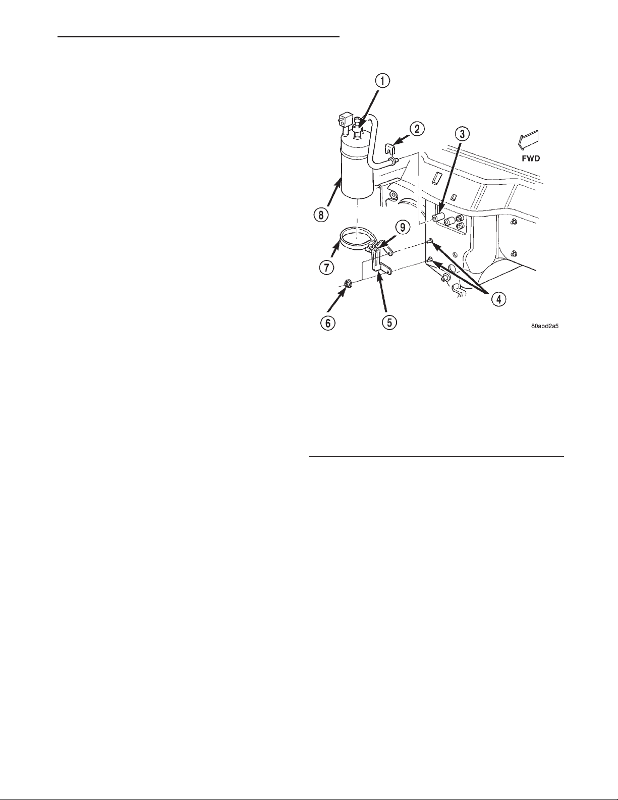
XJ HEATING AND AIR CONDITIONING 24 - 25
REMOVAL AND INSTALLATION (Continued)
to hold one side of the connection stationary, while
loosening or tightening the other side of the connection with a second wrench.
The refrigerant must be recovered completely from
the system before opening any fitting or connection.
Open the fittings with caution, even after the refrigerant has been recovered. If any pressure is noticed
as a fitting is loosened, tighten the fitting and
recover the refrigerant from the system again.
Do not discharge refrigerant into the atmosphere.
Use an R-134a refrigerant recovery/recycling device
that meets SAE Standard J2210.
The refrigerant system will remain chemically stable as long as pure, moisture-free R-134a refrigerant
and refrigerant oil is used. Dirt, moisture, or air can
upset this chemical stability. Operational troubles or
serious damage can occur if foreign material is
present in the refrigerant system.
When it is necessary to open the refrigerant system, have everything needed to service the system
ready. The refrigerant system should not be left open
to the atmosphere any longer than necessary. Cap or
plug all lines and fittings as soon as they are opened
to prevent the entrance of dirt and moisture. All lines
and components in parts stock should be capped or
sealed until they are to be installed.
All tools, including the refrigerant recycling equipment, the manifold gauge set, and test hoses should
be kept clean and dry. All tools and equipment must
be designed for R-134a refrigerant.
ACCUMULATOR
1 – LOW PRESSURE CYCLING CLUTCH SWITCH
2 – CLIP
3 – EVAPORATOR
4 – STUDS
5 – BRACKET
6 – NUTS
7 – BAND
8 – ACCUMULATOR
9 – SCREW
Fig. 14 Accumulator Remove/Install
WARNING: REVIEW THE WARNINGS AND CAUTIONS IN THE FRONT OF THIS GROUP BEFORE
PERFORMING THE FOLLOWING OPERATION.
REMOVAL
(1) Disconnect and isolate the battery negative
cable.
(2) Recover the refrigerant from the refrigerant
system. See Refrigerant Recovery in this group for
the procedures.
(3) Unplug the wire harness connector from the
low pressure cycling clutch switch.
(4) Loosen the screw that secures the accumulator
retaining band to the support bracket on the dash
panel (Fig. 14).
(5) Disconnect the suction line from the accumulator outlet tube refrigerant line fitting. See Refrigerant Line Coupler in this group for the procedures.
Install plugs in, or tape over all of the opened refrigerant line fittings.
(6) Disconnect the accumulator inlet tube refrigerant line fitting from the evaporator outlet tube. See
Refrigerant Line Coupler in this group for the proce-
dures. Install plugs in, or tape over all of the opened
refrigerant line fittings.
(7) Pull the accumulator and retaining band unit
forward until the screw in the band is clear of the
slotted hole in the support bracket on the dash panel.
(8) Remove the accumulator from the vehicle.
INSTALLATION
(1) Install the accumulator and retaining band as
a unit by sliding the screw in the band into the slotted hole in the support bracket on the dash panel.
(2) Remove the tape or plugs from the refrigerant
line fittings on the accumulator inlet tube and the
evaporator outlet tube. Connect the accumulator inlet
tube refrigerant line coupler to the evaporator outlet
tube. See Refrigerant Line Coupler in this group for
the procedures.
(3) Tighten the accumulator retaining band screw
to 5 N·m (45 in. lbs.).
(4) Remove the tape or plugs from the refrigerant
line fittings on the suction line and the accumulator
outlet tube. Connect the suction line to the accumu-
Page 26
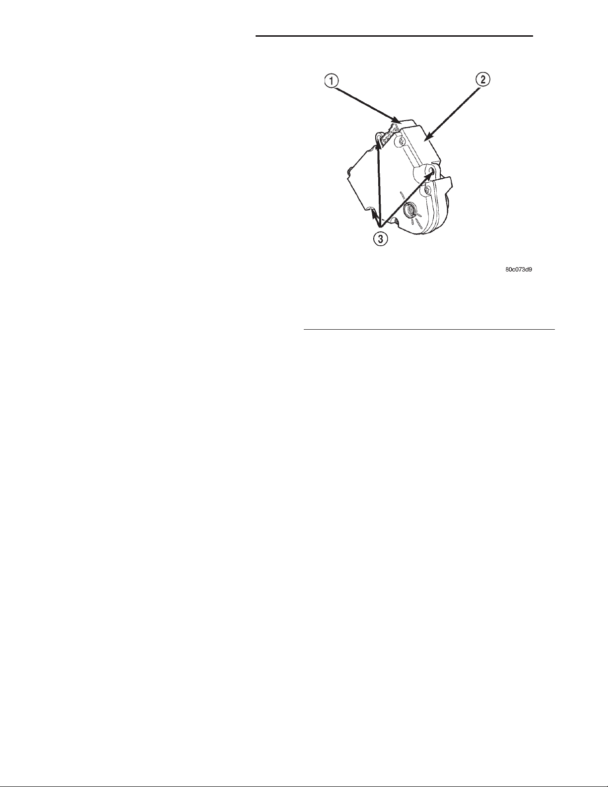
24 - 26 HEATING AND AIR CONDITIONING XJ
REMOVAL AND INSTALLATION (Continued)
lator outlet tube refrigerant line coupler. See Refrigerant Line Coupler in this group for the procedures.
(5) Plug the wire harness connector into the low
pressure cycling clutch switch.
(6) Connect the battery negative cable.
(7) Evacuate the refrigerant system. See Refrigerant System Evacuate in this group for the procedures.
(8) Charge the refrigerant system. See Refrigerant
System Charge in this group for the procedures.
NOTE: If the accumulator is replaced, add 120 milliliters (4 fluid ounces) of refrigerant oil to the
refrigerant system. Use only refrigerant oil of the
type recommended for the compressor in the vehicle.
BLEND-AIR DOOR MOTOR
WARNING: ON VEHICLES EQUIPPED WITH AIRBAGS, REFER TO GROUP 8M - PASSIVE
RESTRAINT SYSTEMS BEFORE ATTEMPTING ANY
STEERING WHEEL, STEERING COLUMN, OR
INSTRUMENT PANEL COMPONENT DIAGNOSIS OR
SERVICE. FAILURE TO TAKE THE PROPER PRECAUTIONS COULD RESULT IN ACCIDENTAL AIRBAG DEPLOYMENT AND POSSIBLE PERSONAL
INJURY.
REMOVAL
(1) Disconnect and isolate the battery negative
cable.
(2) Disconnect the wire connector from the blendair door motor.
(3) Remove the screws that secure the blend-air
door motor to the housing (Fig. 15).
(4) Remove the blend-air door motor.
INSTALLATION
(1) Reverse the removal procedures for installation.
(2) Install and tighten the screws that secures the
blend-air door motor to the housing. Tighten the
mounting screws to 1 N·m (10 in. lbs.).
(3) Connect the battery negative cable.
BLOWER MOTOR
REMOVAL
(1) If the vehicle is equipped with air conditioning,
recover the refrigerant from the refrigerant system.
See Refrigerant Recovery in this group for the procedures.
(2) Disconnect and isolate the battery negative
cable.
Fig. 15 Blend-Air Door Motor
1 – ELECTRICAL CONNECTOR
2 – BLEND-AIR DOOR MOTOR
3 – SCREW MOUNTING POINTS
(3) If the vehicle is equipped with air conditioning,
the accumulator must be relocated in order to service
the blower motor. This is done by loosening the accumulator retaining band screw and disconnecting the
accumulator inlet tube from the evaporator outlet
tube. The accumulator can then be moved far enough
to access and remove the blower motor. See Accumulator in this group for the procedures.
(4) Unplug the blower motor wire harness connector (Fig. 16).
(5) Remove the three screws that secure the
blower motor and wheel assembly to the heater-A/C
housing.
(6) Rotate and tilt the blower motor unit as needed
for clearance to remove the blower motor and wheel
from the heater-A/C housing.
INSTALLATION
(1) Align and install the blower motor and wheel
assembly into the heater-A/C housing.
(2) Install and tighten the three screws that secure
the blower motor and wheel assembly to the heaterA/C housing. Tighten the mounting screws to 2.2
N·m (20 in. lbs.).
(3) Plug in the blower motor wire harness connector.
(4) If the vehicle is equipped with air conditioning,
connect the accumulator inlet tube to the evaporator
outlet tube and tighten the accumulator retaining
band screw. See Accumulator in this group for the
procedures.
(5) Connect the battery negative cable.
Page 27
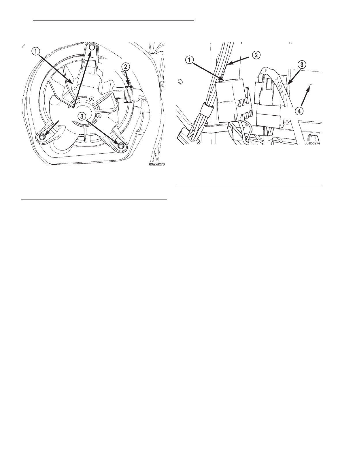
XJ HEATING AND AIR CONDITIONING 24 - 27
REMOVAL AND INSTALLATION (Continued)
Fig. 17 Blower Motor Relay Remove/Install
1 – BLOWER MOTOR RELAY
2 – VACUUM HARNESS
Fig. 16 Blower Motor Remove/Install
1 – BLOWER MOTOR
2 – WIRE HARNESS CONNECTOR
3 – MOUNTING SCREWS
(6) If the vehicle is equipped with air conditioning,
evacuate the refrigerant system. See Refrigerant System Evacuate in this group for the procedures.
(7) If the vehicle is equipped with air conditioning,
charge the refrigerant system. See Refrigerant System Charge in this group for the procedures.
BLOWER MOTOR RELAY
WARNING: ON VEHICLES EQUIPPED WITH AIRBAGS, REFER TO GROUP 8M - PASSIVE
RESTRAINT SYSTEMS BEFORE ATTEMPTING ANY
STEERING WHEEL, STEERING COLUMN, OR
INSTRUMENT PANEL COMPONENT DIAGNOSIS OR
SERVICE. FAILURE TO TAKE THE PROPER PRECAUTIONS COULD RESULT IN ACCIDENTAL AIRBAG DEPLOYMENT AND POSSIBLE PERSONAL
INJURY.
(1) Disconnect and isolate the battery negative
cable.
(2) Roll the glove box down from the instrument
panel. Refer to Glove Box in Group 8E - Instrument
Panel Systems for the procedures.
(3) Reach through the instrument panel glove box
opening to locate the blower motor relay (Fig. 17).
(4) Unplug the blower motor relay from its wire
harness connector.
(5) Install the blower motor relay by aligning the
relay terminals with the cavities in the wire harness
connector and pushing the relay firmly into place.
3 – HEATER-A/C WIRE HARNESS CONNECTOR
4 – HEATER-A/C HOUSING
(6) Roll the glove box back up into the instrument
panel. Refer to Glove Box in Group 8E - Instrument
Panel Systems for the procedures.
(7) Connect the battery negative cable.
(8) Test the relay operation.
BLOWER MOTOR RESISTOR
WARNING: ON VEHICLES EQUIPPED WITH AIRBAGS, REFER TO GROUP 8M - PASSIVE
RESTRAINT SYSTEMS BEFORE ATTEMPTING ANY
STEERING WHEEL, STEERING COLUMN, OR
INSTRUMENT PANEL COMPONENT DIAGNOSIS OR
SERVICE. FAILURE TO TAKE THE PROPER PRECAUTIONS COULD RESULT IN ACCIDENTAL AIRBAG DEPLOYMENT AND POSSIBLE PERSONAL
INJURY.
(1) Disconnect and isolate the battery negative
cable.
(2) Remove the kick cover from the heater-A/C
housing. See Kick Cover in this group for the procedures.
(3) Pull out the lock on the blower motor resistor
wire harness connector to unlock the connector latch
(Fig. 18).
(4) Depress the latch on the blower motor resistor
wire harness connector and unplug the connector
from the resistor.
(5) Remove the two screws that secure the resistor
to the heater-A/C housing.
(6) Remove the resistor from the heater-A/C housing.
(7) Reverse the removal procedures to install.
Tighten the mounting screws to 2.2 N·m (20 in lbs.).
Page 28
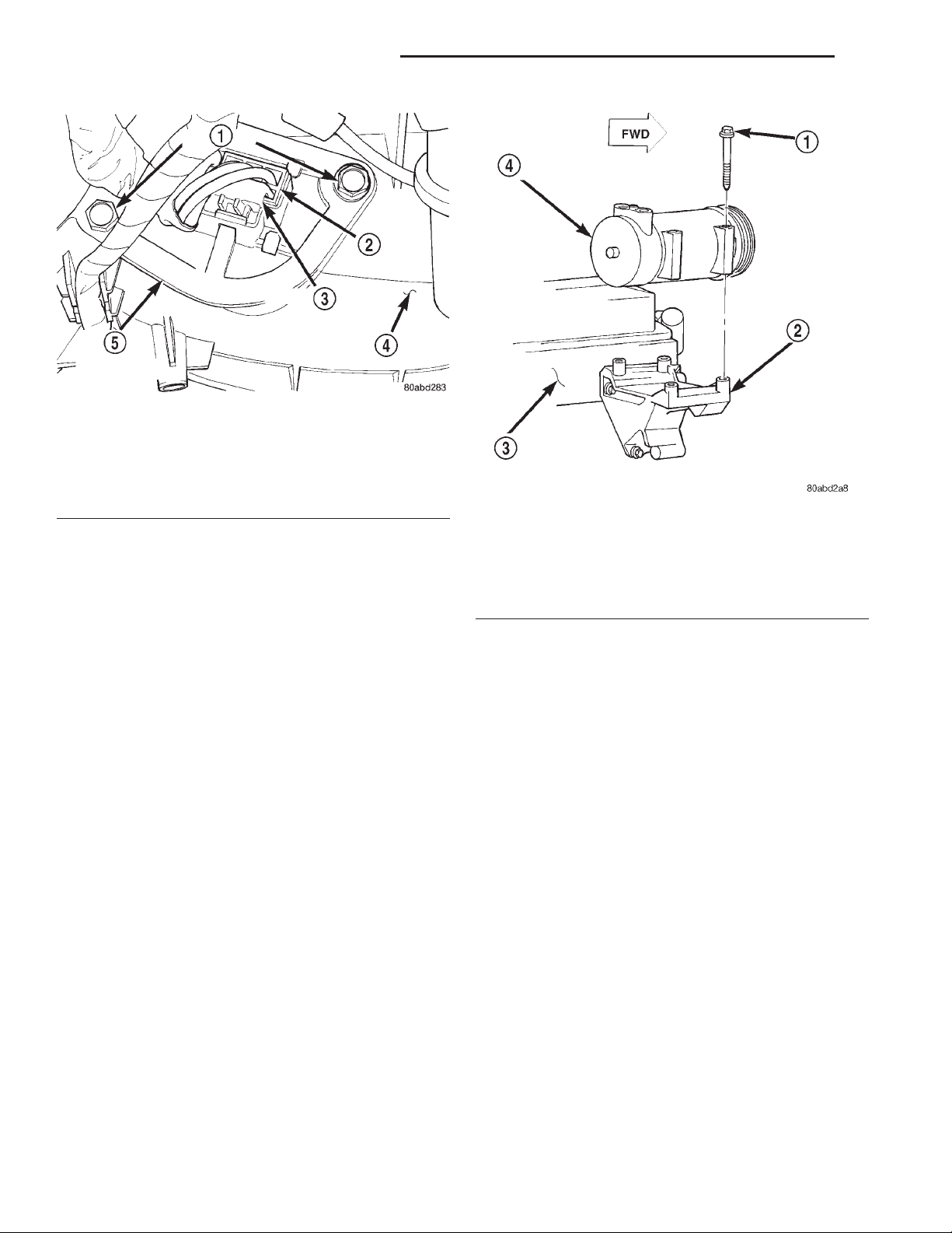
24 - 28 HEATING AND AIR CONDITIONING XJ
REMOVAL AND INSTALLATION (Continued)
Fig. 18 Blower Motor Resistor Remove/Install
1 – SCREWS
2 – WIRE HARNESS CONNECTOR
3 – CONNECTOR LOCK
4 – HEATER-A/C HOUSING
5 – BLOWER MOTOR RESISTOR
COMPRESSOR
The compressor may be removed and repositioned
without disconnecting the refrigerant lines or discharging the refrigerant system. Discharging is not
necessary if servicing the compressor clutch or clutch
coil, the engine, the cylinder head, or the generator.
Fig. 19 Compressor Remove/Install - All 2.5L/4.0L
Engines
1 – BOLT
2 – MOUNTING BRACKET
3 – ENGINE
4 – COMPRESSOR
INSTALLATION
WARNING: REVIEW THE WARNINGS AND CAUTIONS IN THE FRONT OF THIS GROUP BEFORE
PERFORMING THE FOLLOWING OPERATION.
REMOVAL
(1) Recover the refrigerant from the refrigerant
system. See Refrigerant Recovery in this group for
the procedures.
(2) Disconnect and isolate the battery negative
cable.
(3) Remove the serpentine drive belt. Refer to
Group 7 - Cooling System for the procedures.
(4) Unplug the compressor clutch coil wire harness
connector.
(5) Remove the suction and discharge refrigerant
line manifold from the compressor. See Suction and
Discharge Line in this group for the procedures.
Install plugs in, or tape over all of the opened refrigerant fittings.
(6) Remove the four bolts that secure the compressor to the mounting bracket (Fig. 19).
(7) Remove the compressor from the mounting
bracket.
NOTE: If a replacement compressor is being
installed, be certain to check the refrigerant oil
level. See Refrigerant Oil Level in this group for the
procedures. Use only refrigerant oil of the type recommended for the compressor in the vehicle.
(1) Install the compressor to the mounting bracket.
Tighten the four mounting bolts as follows:
• All 2.5L and 4.0L engines - 27 N·m (20 ft. lbs.)
(2) Remove the tape or plugs from all of the
opened refrigerant line fittings. Install the suction
and discharge line manifold to the compressor. See
Suction and Discharge Line in this group for the procedures.
(3) Install the serpentine drive belt. Refer to
Group 7 - Cooling System for the procedures.
(4) Plug in the compressor clutch coil wire harness
connector.
(5) Connect the battery negative cable.
(6) Evacuate the refrigerant system. See Refrigerant System Evacuate in this group for the procedures.
(7) Charge the refrigerant system. See Refrigerant
System Charge in this group for the procedures.
Page 29
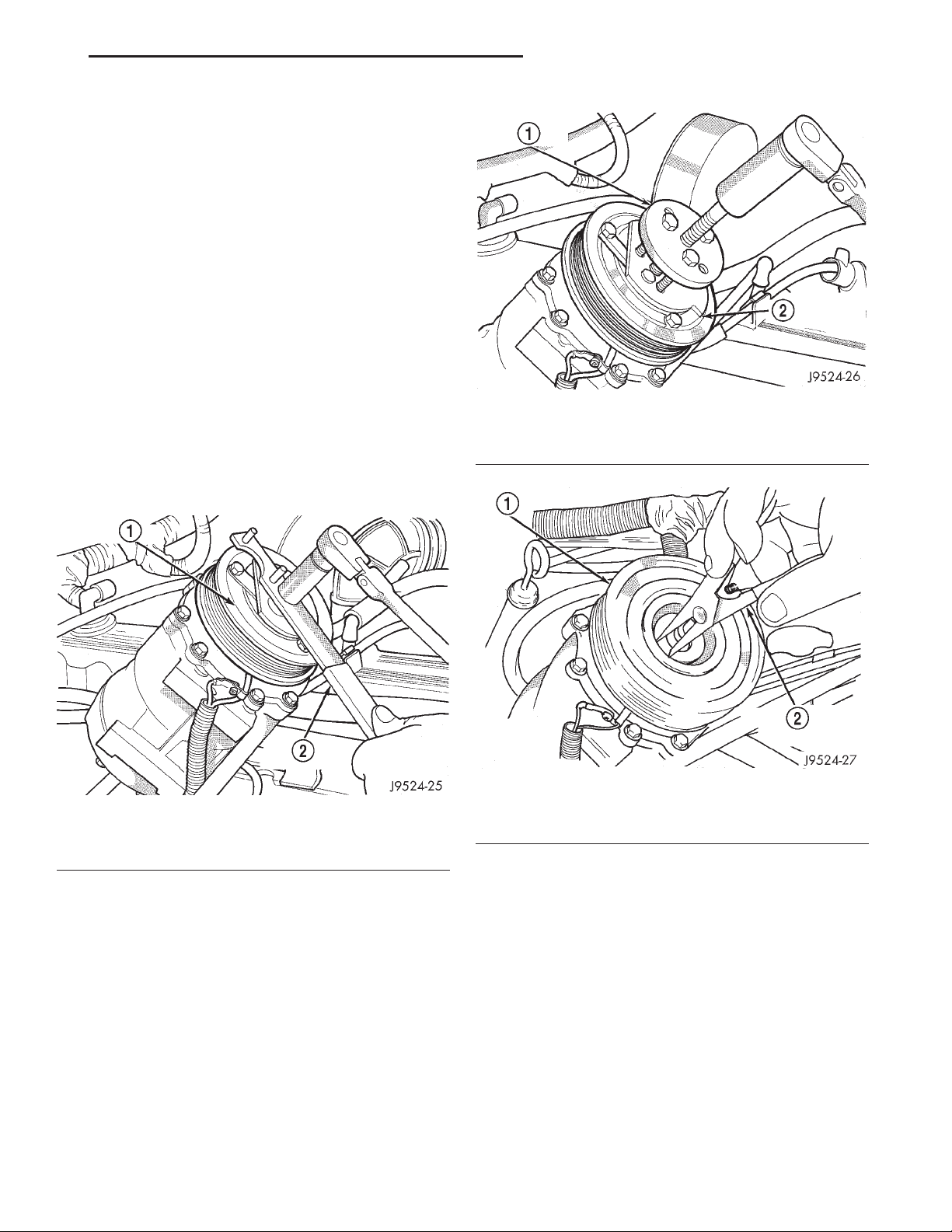
XJ HEATING AND AIR CONDITIONING 24 - 29
REMOVAL AND INSTALLATION (Continued)
COMPRESSOR CLUTCH
The refrigerant system can remain fully-charged
during compressor clutch, pulley, or coil replacement.
The compressor clutch can be serviced in the vehicle.
REMOVAL
(1) Disconnect and isolate the battery negative
cable.
(2) Remove the serpentine drive belt. Refer to
Group 7 - Cooling System for the procedures.
(3) Unplug the compressor clutch coil wire harness
connector.
(4) Remove the four bolts that secure the compressor to the mounting bracket.
(5) Remove the compressor from the mounting
bracket. Support the compressor in the engine compartment while servicing the clutch.
(6) Insert the two pins of the spanner wrench
(Special Tool C-4489) into the holes of the clutch
plate. Hold the clutch plate stationary and remove
the hex nut (Fig. 20).
1 – CLUTCH PLATE PULLER
2 – CLUTCH PLATE
Fig. 21 Clutch Plate Remove
Fig. 20 Clutch Nut Remove
1 – CLUTCH PLATE
2 – SPANNER
(7) Remove the clutch plate with a puller (Special
Tool C-6461) (Fig. 21).
(8) Remove the compressor shaft key and the
clutch shims.
(9) Remove the external front housing snap ring
with snap ring pliers (Fig. 22).
(10) Install the lip of the rotor puller (Special Tool
C-6141-1) into the snap ring groove exposed in the
previous step, and install the shaft protector (Special
Tool C-6141-2) (Fig. 23).
(11) Install the puller through-bolts (Special Tool
C-6461) through the puller flange and into the jaws
of the rotor puller and tighten (Fig. 24). Turn the
Fig. 22 External Snap Ring Remove
1 – PULLEY
2 – SNAP RING PLIERS
puller center bolt clockwise until the rotor pulley is
free.
(12) Remove the screw and retainer from the
clutch coil lead wire harness on the compressor front
housing (Fig. 25).
(13) Remove the snap ring from the compressor
hub and remove the clutch field coil (Fig. 26). Slide
the clutch field coil off of the compressor hub.
INSPECTION
Examine the friction surfaces of the clutch pulley
and the front plate for wear. The pulley and front
plate should be replaced if there is excessive wear or
scoring.
If the friction surfaces are oily, inspect the shaft
and nose area of the compressor for oil. Remove the
Page 30
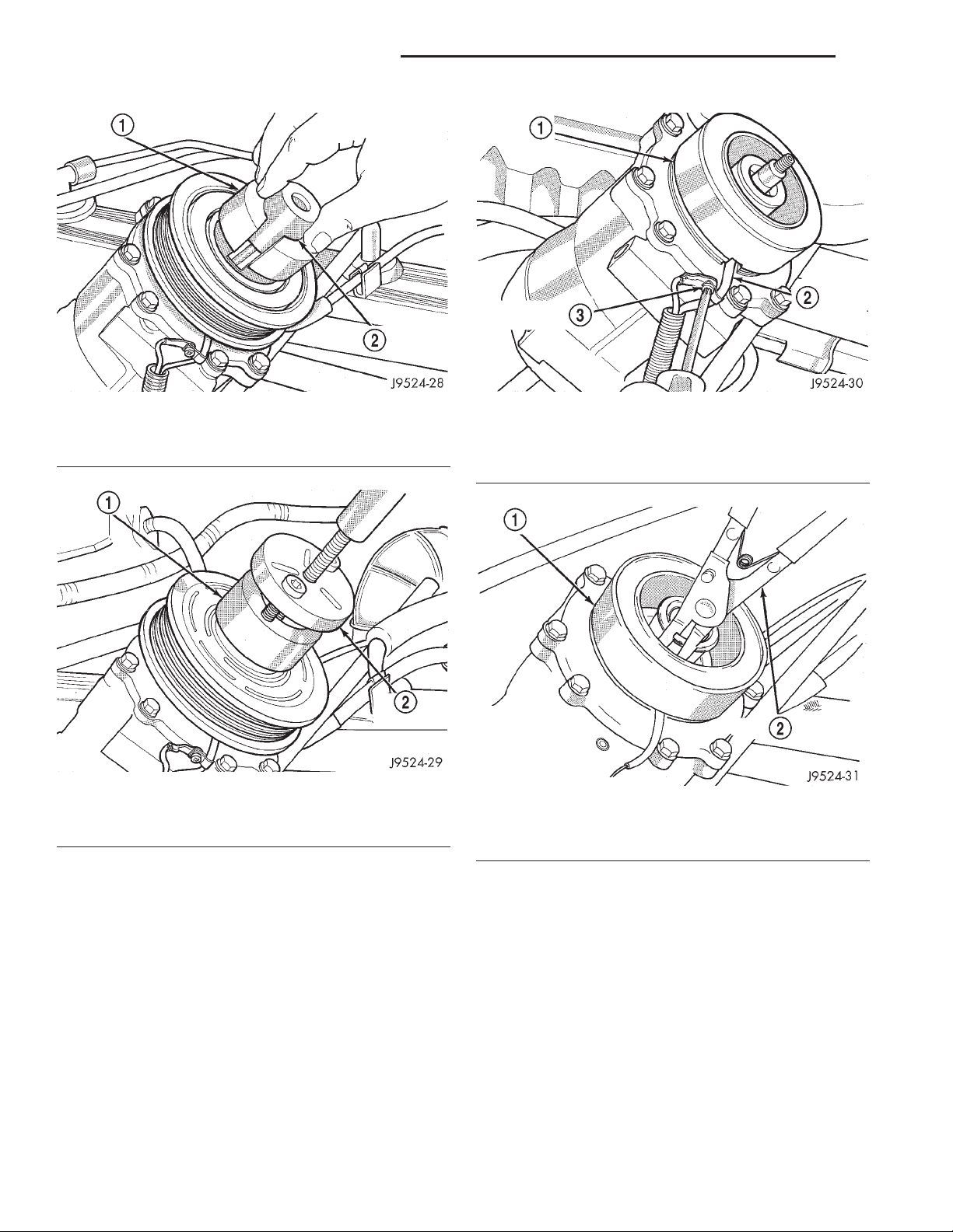
24 - 30 HEATING AND AIR CONDITIONING XJ
REMOVAL AND INSTALLATION (Continued)
Fig. 23 Shaft Protector and Puller
1 – PULLER JAW
2 – SHAFT PROTECTOR
Fig. 24 Install Puller Plate
1 – PULLER JAW
2 – PULLER
Fig. 25 Clutch Coil Lead Wire Harness
1 – COIL
2 – COIL WIRE
3 – RETAINER SCREW
Fig. 26 Clutch Field Coil Snap Ring Remove
1 – COIL
2 – SNAP RING PLIERS
felt from the front cover. If the felt is saturated with
oil, the shaft seal is leaking and the compressor must
be replaced.
Check the clutch pulley bearing for roughness or
excessive leakage of grease. Replace the bearing, if
required.
INSTALLATION
(1) Install the clutch field coil and snap ring.
(2) Install the clutch coil lead wire harness retaining clip on the compressor front housing and tighten
the retaining screw.
(3) Align the rotor assembly squarely on the front
compressor housing hub.
(4) Install the pulley bearing assembly with the
installer (Special Tool C-6871) (Fig. 27). Thread the
installer on the shaft, then turn the nut until the
pulley assembly is seated.
(5) Install the external front snap ring with snap
ring pliers. The bevel side of the snap ring must be
facing outward. Press the snap ring to make sure it
is properly seated in the groove.
CAUTION: If the snap ring is not fully seated in the
groove it will vibrate out, resulting in a clutch failure and severe damage to the front housing of the
compressor.
(6) Install the compressor shaft key and the original clutch shims on the compressor shaft.
Page 31
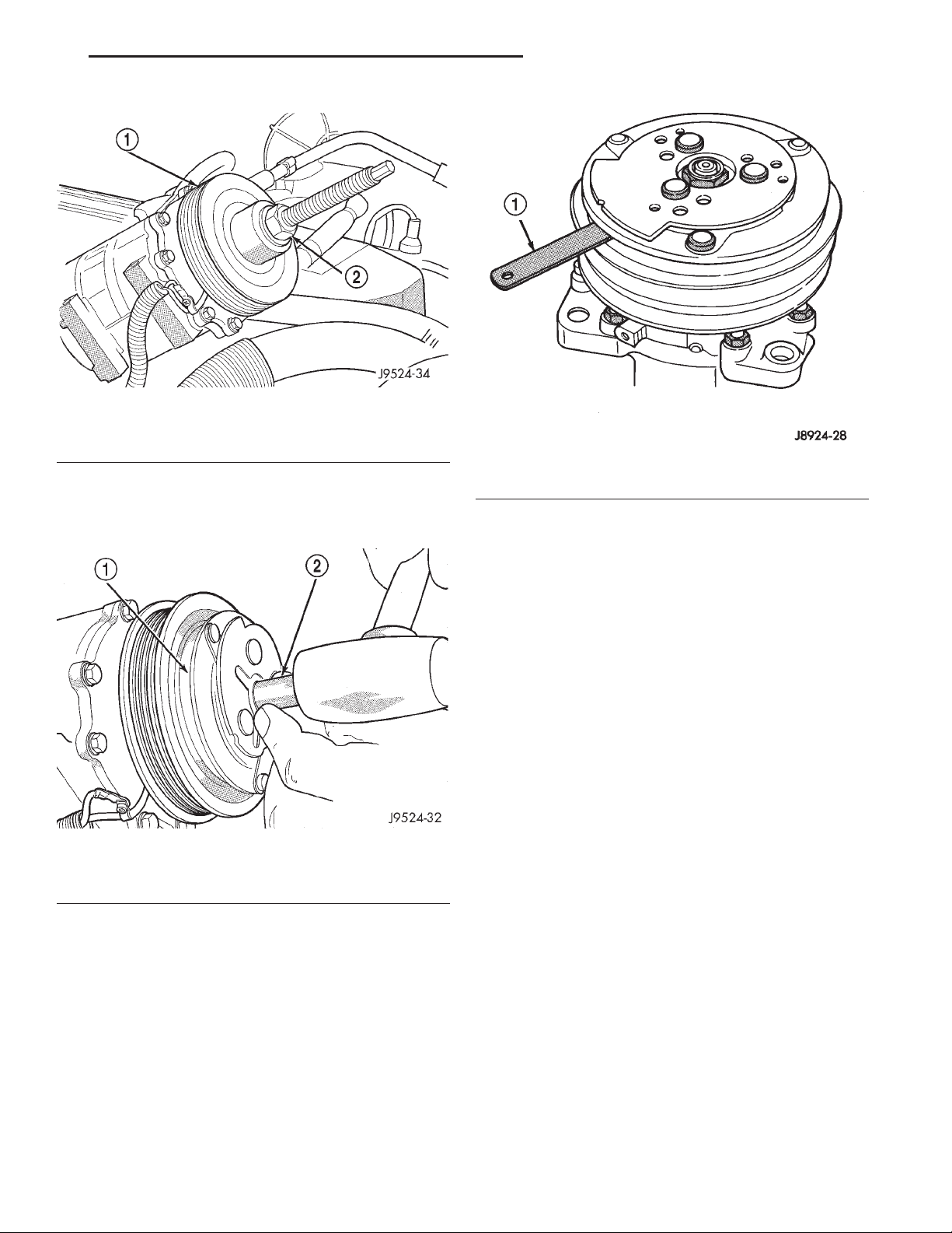
XJ HEATING AND AIR CONDITIONING 24 - 31
REMOVAL AND INSTALLATION (Continued)
Fig. 27 Clutch Pulley Install
1 – PULLEY BEARING ASSEMBLY
2 – INSTALLER
Fig. 29 Check Clutch Air Gap
(7) Install the clutch plate with the driver (Special
Tool C-6463) (Fig. 28). Install the shaft hex nut and
tighten to 14.4 N·m (10.5 ft. lbs.).
1 – FEELER GAUGE
did not have a clutch, use 1.0, 0.50, and 0.13 millimeter (0.040, 0.020, and 0.005 inch) shims from the
clutch hardware package that is provided with the
new clutch.
Fig. 28 Clutch Plate Driver
1 – CLUTCH PLATE
2 – DRIVER
(8) Check the clutch air gap with a feeler gauge
(Fig. 29). If the air gap does not meet the specification, add or subtract shims as required. The air gap
specification is 0.41 to 0.79 millimeter (0.016 to 0.031
inch). If the air gap is not consistent around the circumference of the clutch, lightly pry up at the minimum variations. Lightly tap down at the points of
maximum variation.
NOTE: The air gap is determined by the spacer
shims. When installing an original, or a new clutch
assembly, try the original shims first. When installing a new clutch onto a compressor that previously
(9) Reverse the remaining removal procedures to
complete the installation.
CLUTCH BREAK-IN
After a new compressor clutch has been installed,
cycle the compressor clutch approximately twenty
times (five seconds on, then five seconds off). During
this procedure, set the heater-A/C control to the
Recirculation Mode, the blower motor switch in the
highest speed position, and the engine speed at 1500
to 2000 rpm. This procedure (burnishing) will seat
the opposing friction surfaces and provide a higher
compressor clutch torque capability.
COMPRESSOR CLUTCH RELAY
(1) Disconnect and isolate the battery negative
cable.
(2) Remove the cover from the Power Distribution
Center (PDC) (Fig. 30).
(3) Refer to the label on the PDC for compressor
clutch relay identification and location.
(4) Unplug the compressor clutch relay from the
PDC.
(5) Install the compressor clutch relay by aligning
the relay terminals with the cavities in the PDC and
pushing the relay firmly into place.
(6) Install the PDC cover.
(7) Connect the battery negative cable.
(8) Test the relay operation.
Page 32
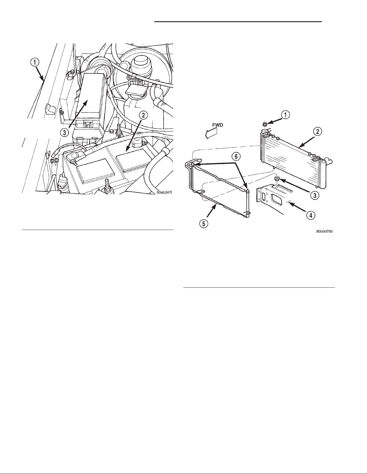
24 - 32 HEATING AND AIR CONDITIONING XJ
REMOVAL AND INSTALLATION (Continued)
line fitting at the condenser outlet. See Refrigerant
Line Coupler in this group for the procedures. Install
plugs in, or tape over all of the opened refrigerant
line fittings.
(5) Remove the radiator and the condenser from
the vehicle as a unit. Refer to Group 7 - Cooling System for the procedures.
(6) Remove the two nuts that secure the condenser
studs to the upper brackets of the radiator (Fig. 31).
Fig. 30 Power Distribution Center
1 – RIGHT FENDER
2 – BATTERY
3 – POWER DISTRIBUTION CENTER
CONDENSER
WARNING: REVIEW THE WARNINGS AND CAUTIONS IN THE FRONT OF THIS GROUP BEFORE
PERFORMING THE FOLLOWING OPERATION.
CAUTION: Before removing the condenser, note the
location of each of the radiator and condenser air
seals. These seals are used to direct air through the
condenser and radiator. The air seals must be reinstalled in their proper locations in order for the air
conditioning and engine cooling systems to perform as designed.
REMOVAL
(1) Disconnect and isolate the battery negative
cable.
(2) Recover the refrigerant from the refrigerant
system. See Refrigerant Recovery in this group for
the procedures.
(3) Disconnect the discharge line refrigerant line
fitting at the condenser inlet. See Refrigerant Line
Coupler in this group for the procedures. Install
plugs in, or tape over all of the opened refrigerant
line fittings.
(4) Disconnect the liquid line (Left-Hand Drive) or
liquid line jumper (Right-Hand Drive) refrigerant
Fig. 31 Condenser Remove/Install
1 – NUT
2 – RADIATOR
3 – GROMMET
4 – LOWER CROSSMEMBER
5 – CONDENSER
6 – STUDS
(7) Slide the condenser down from the radiator far
enough for the condenser studs to clear the upper
radiator bracket holes, and for the lower condenser
bracket holes to clear the dowel pins on the bottom of
the radiator.
(8) Remove the condenser from the radiator.
INSTALLATION
(1) Install the holes of the condenser lower brackets over the dowel pins on the bottom of the radiator.
(2) Slide the condenser upwards until both of the
condenser studs are installed through the holes in
the radiator upper brackets. Tighten the mounting
nuts to 5.3 N·m (47 in. lbs.).
(3) Renstall the radiator and condenser unit in the
vehicle. Refer to Group 7 - Cooling System for the
procedures.
(4) Remove the tape or plugs from the refrigerant
line fittings on the condenser outlet and the liquid
line (Left-Hand Drive) or the liquid line jumper
(Right-Hand Drive). Install the liquid line or the liq-
Page 33
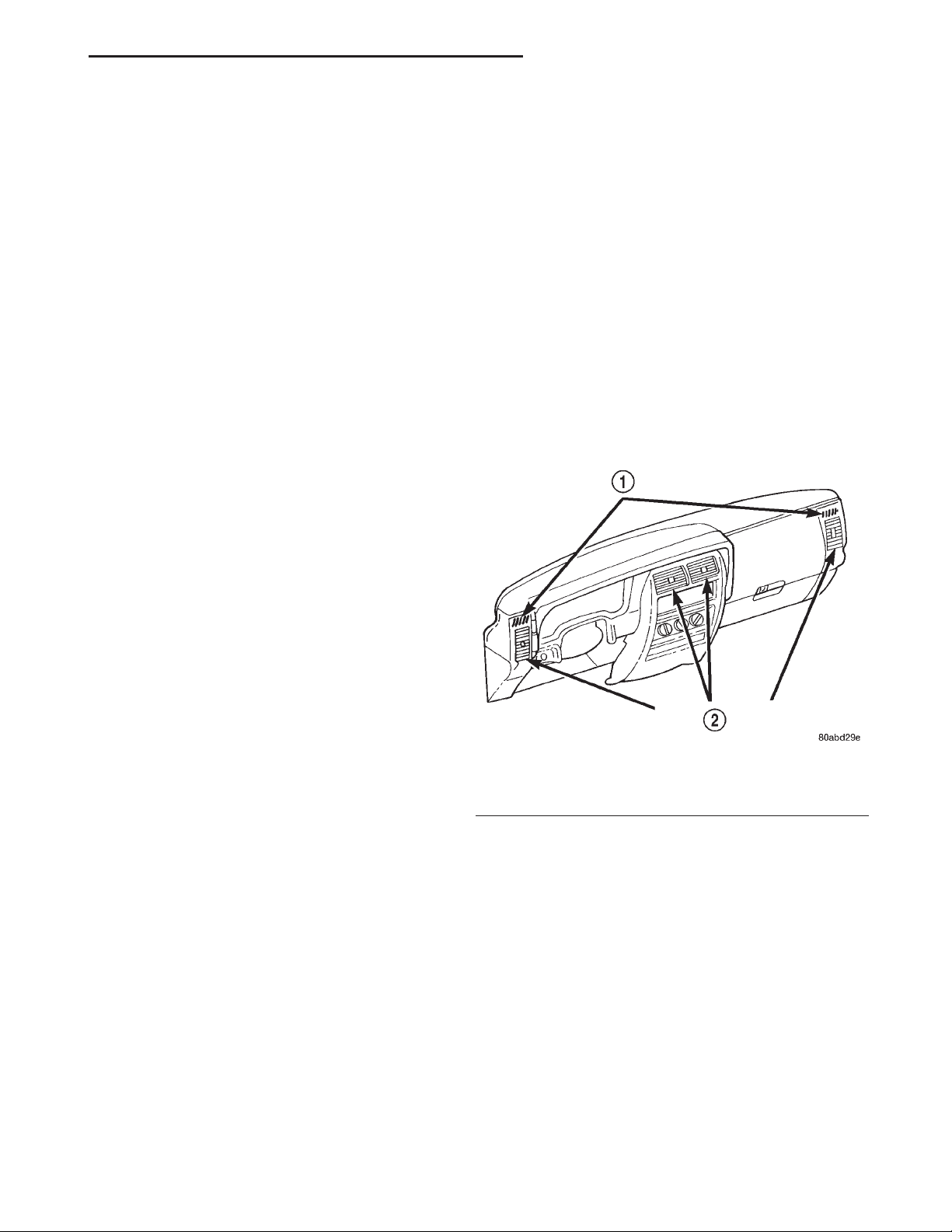
XJ HEATING AND AIR CONDITIONING 24 - 33
REMOVAL AND INSTALLATION (Continued)
uid line jumper to the condenser outlet. See Refrigerant Line Coupler in this group for the procedures.
(5) Remove the tape or plugs from the refrigerant
line fittings on the condenser inlet and the discharge
line. Connect the discharge line to the condenser
inlet. See Refrigerant Line Coupler in this group for
the procedures.
(6) Connect the battery negative cable.
(7) Evacuate the refrigerant system. See Refrigerant System Evacuate in this group for the procedures.
(8) Charge the refrigerant system. See Refrigerant
System Charge in this group for the procedures.
NOTE: If the condenser is replaced, add 30 milliliters (1 fluid ounce) of refrigerant oil to the refrigerant system. Use only refrigerant oil of the type
recommended for the compressor in the vehicle.
DUAL FUNCTION HIGH PRESSURE SWITCH/ HIGH PRESSURE CUT-OFF SWITCH
REMOVAL
(1) Disconnect and isolate the battery negative
cable.
(2) Unplug the wire harness connector from the
dual function high pressure switch or the high pressure cut-off switch, which is mounted to a fitting on
the non-flexible section of the discharge line nearest
the compressor.
(3) Unscrew the high pressure switch from the discharge line fitting.
(4) Remove the high pressure switch from the
vehicle.
(5) Remove the O-ring seal from the discharge line
fitting and discard.
INSTALLATION
(1) Lubricate a new O-ring seal with clean refrigerant oil and install it on the discharge line fitting.
Use only the specified O-rings as they are made of a
special material for the R-134a system. Use only
refrigerant oil of the type recommended for the compressor in the vehicle.
(2) Install and tighten the high pressure switch on
the discharge line fitting.
(3) Plug the wire harness connector into the high
pressure cut-off switch.
(4) Connect the battery negative cable.
DUCTS AND OUTLETS
WARNING: ON VEHICLES EQUIPPED WITH AIRBAGS, REFER TO GROUP 8M - PASSIVE
RESTRAINT SYSTEMS BEFORE ATTEMPTING ANY
STEERING WHEEL, STEERING COLUMN, OR
INSTRUMENT PANEL COMPONENT DIAGNOSIS OR
SERVICE. FAILURE TO TAKE THE PROPER PRECAUTIONS COULD RESULT IN ACCIDENTAL AIRBAG DEPLOYMENT AND POSSIBLE PERSONAL
INJURY.
PANEL OUTLET DUCTS
The panel outlet ducts are integral to the instrument panel assembly. Refer to Instrument Panel
Assembly in Group 8E - Instrument Panel Systems
for the procedures.
PANEL OUTLET BARRELS
(1) Use a trim stick or another suitable wide flatbladed tool to gently pry the panel outlet barrel out
of the panel outlet housing (Fig. 32). The barrel is
retained by a light snap fit.
Fig. 32 Panel Outlet Barrels
1 – DEMISTER OUTLETS
2 – PANEL OUTLET BARRELS
(2) To install, position the barrel in the panel outlet housing and press firmly until the barrel snaps
into place.
DEMISTER OUTLETS
The side window demister outlets are integral to
the instrument panel end caps. Refer to Instrument
Panel End Cap in Group 8E - Instrument Panel Systems for the procedures.
DEFROST DUCT/DEMISTER ADAPTER
(1) Remove the instrument panel assembly from
the vehicle. Refer to Instrument Panel Assembly in
Group 8E - Instrument Panel Systems for the procedures.
(2) Disconnect the demister hoses from the defrost
duct/demister adapter (Fig. 33).
Page 34
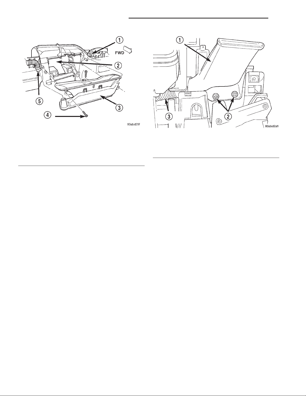
24 - 34 HEATING AND AIR CONDITIONING XJ
REMOVAL AND INSTALLATION (Continued)
Fig. 33 Defrost Duct/Demister Adapter
1 – HOSE
2 – INSTRUMENT PANEL
3 – DEFROST DUCT/DEMISTER ADAPTER
4 – SCREW
5 – HOSE
(3) Remove the three screws that secure the
defrost duct/demister adapter to the instrument
panel.
(4) Remove the defrost duct/demister adapter from
the instrument panel.
(5) Reverse the removal procedures to install.
Tighten the mounting screws to 2.2 N·m (20 in. lbs.).
DEMISTER HOSES
(1) Remove the instrument panel assembly from
the vehicle. Refer to Instrument Panel Assembly in
Group 8E - Instrument Panel Systems for the procedures.
(2) Disconnect the ends of the demister hose from
the demister duct (Fig. 34) and the defrost duct/demister adapter (Fig. 33).
(3) Reverse the removal procedures to install.
DEMISTER DUCTS
(1) Remove the instrument panel assembly from
the vehicle. Refer to Instrument Panel Assembly in
Group 8E - Instrument Panel Systems for the procedures.
(2) Remove the end cap from the instrument
panel. Refer to Instrument Panel End Cap in Group
8E - Instrument Panel Systems for the procedures.
(3) Disconnect the demister hoses from the demister duct (Fig. 34).
(4) Remove the two screws that secure the demister duct to the top of the instrument panel.
(5) Remove the demister duct from the instrument
panel.
Fig. 34 Demister Duct Remove/Install
1 – DEMISTER DUCT
2 – SCREWS
3 – DEMISTER HOSE
(6) Reverse the removal procedures to install.
Tighten the mounting screws to 2.2 N·m (20 in. lbs.).
CONSOLE REAR DUCT
(1) Disconnect and isolate the battery negative
cable.
(2) Remove the floor console from the floor panel
transmission tunnel (Fig. 35). Refer to Group 23 Body for the procedures.
(3) Lift the rear of the console rear duct out of the
console rear mounting bracket on the floor panel
transmission tunnel and slide the duct rearward to
disengage it from the floor duct and adapter.
(4) Remove the console rear duct from the vehicle.
(5) Reverse the removal procedures to install.
FLOOR DUCT AND ADAPTER
(1) Remove the instrument panel from the vehicle.
Refer to Instrument Panel Assembly in Group 8E Instrument Panel Systems for the procedures.
(2) Remove the heater-A/C housing from the vehicle. See Heater-A/C Housing in this group for the
procedures.
(3) Remove the three screws that secure the floor
duct and adapter to the heater-A/C housing (Fig. 35).
(4) Remove the floor duct and adapter from the
heater-A/C housing.
(5) Reverse the removal procedures to install.
Tighten the mounting screws to 2.2 N·m (20 in. lbs.).
Page 35
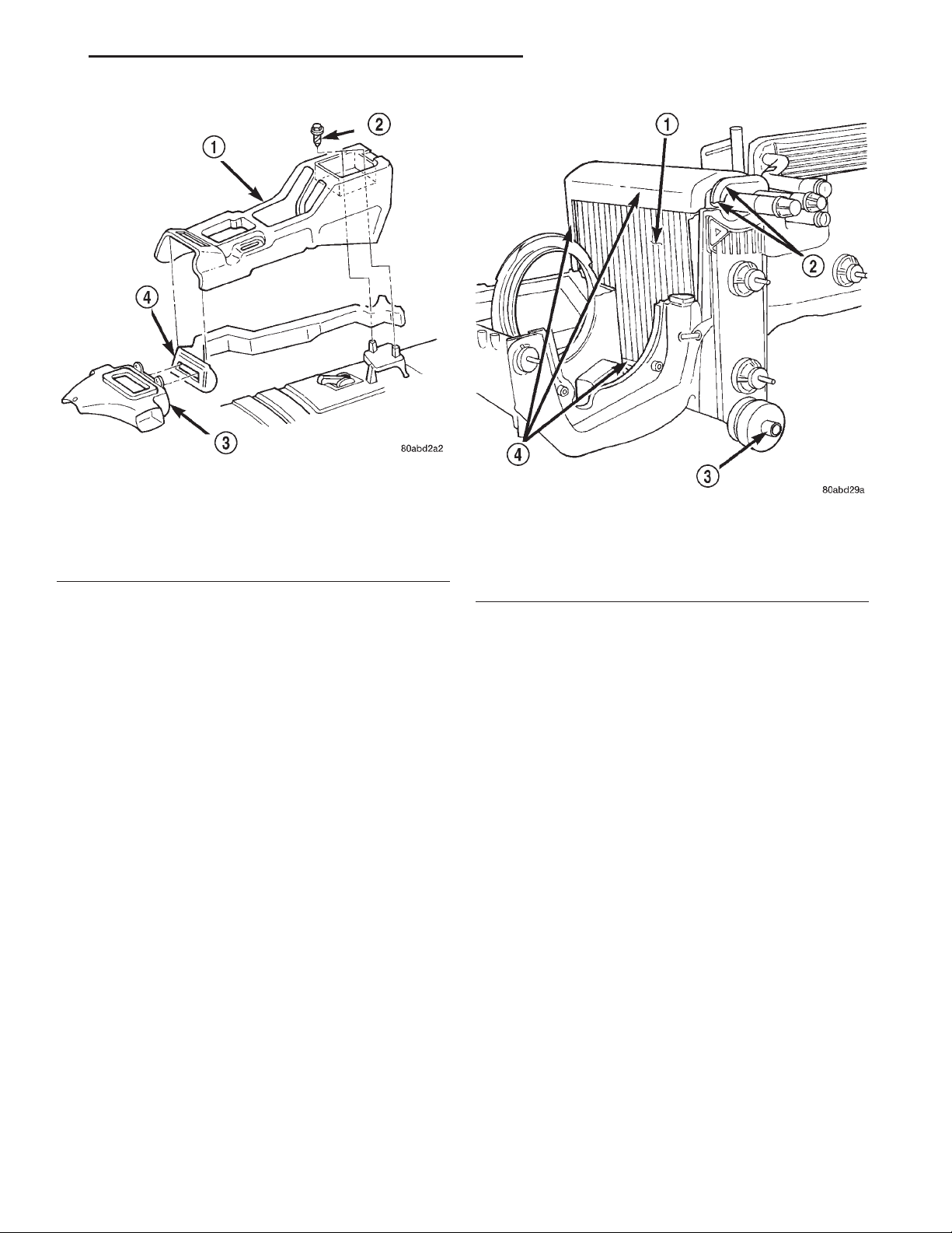
XJ HEATING AND AIR CONDITIONING 24 - 35
REMOVAL AND INSTALLATION (Continued)
Fig. 35 Floor Duct and Console Rear Duct Remove/
Install
1 – FLOOR CONSOLE
2 – SCREW
3 – FLOOR DUCT AND ADAPTER
4 – CONSOLE REAR DUCT
1 – EVAPORATOR COIL
2 – TUBE SEAL
3 – CONDENSATE DRAIN TUBE
4 – FOAM INSULATOR WRAP
Fig. 36 Evaporator Coil Remove/Install
EVAPORATOR COIL
WARNING: ON VEHICLES EQUIPPED WITH AIRBAGS, REFER TO GROUP 8M - PASSIVE
RESTRAINT SYSTEMS BEFORE ATTEMPTING ANY
STEERING WHEEL, STEERING COLUMN, OR
INSTRUMENT PANEL COMPONENT DIAGNOSIS OR
SERVICE. FAILURE TO TAKE THE PROPER PRECAUTIONS COULD RESULT IN ACCIDENTAL AIRBAG DEPLOYMENT AND POSSIBLE PERSONAL
INJURY.
(1) Remove and disassemble the heater-A/C housing. See Heater-A/C Housing in this group for the
procedures.
(2) Lift the evaporator coil unit out of the lower
half of the heater-A/C housing (Fig. 36).
(3) Reverse the removal procedures to install. Be
certain that the evaporator foam insulator wrap and
rubber tube seal are reinstalled.
NOTE: If the evaporator is replaced, add 60 milliliters (2 fluid ounces) of refrigerant oil to the refrigerant system. Use only refrigerant oil of the type
recommended for the compressor in the vehicle.
FIXED ORIFICE TUBE
The fixed orifice tube is located in the liquid line
(Left-Hand Drive) or the liquid line jumper (Right-
Hand Drive) near the condenser. The orifice has filter
screens on the inlet and outlet ends of the tube body.
If the fixed orifice tube is faulty or plugged, the liquid line unit or liquid line jumper unit must be
replaced. See Liquid Line in this group for the service procedures.
HEATER-A/C CONTROL
WARNING: ON VEHICLES EQUIPPED WITH AIRBAGS, REFER TO GROUP 8M - PASSIVE
RESTRAINT SYSTEMS BEFORE ATTEMPTING ANY
STEERING WHEEL, STEERING COLUMN, OR
INSTRUMENT PANEL COMPONENT DIAGNOSIS OR
SERVICE. FAILURE TO TAKE THE PROPER PRECAUTIONS COULD RESULT IN ACCIDENTAL AIRBAG DEPLOYMENT AND POSSIBLE PERSONAL
INJURY.
REMOVAL
(1) Disconnect and isolate the battery negative
cable.
(2) Roll down the glove box from the instrument
panel. Refer to Glove Box in Group 8E - Instrument
Panel Systems for the procedures.
(3) Reach through the instrument panel glove box
opening to access and unplug the two halves of the
heater-A/C vacuum harness connector.
Page 36
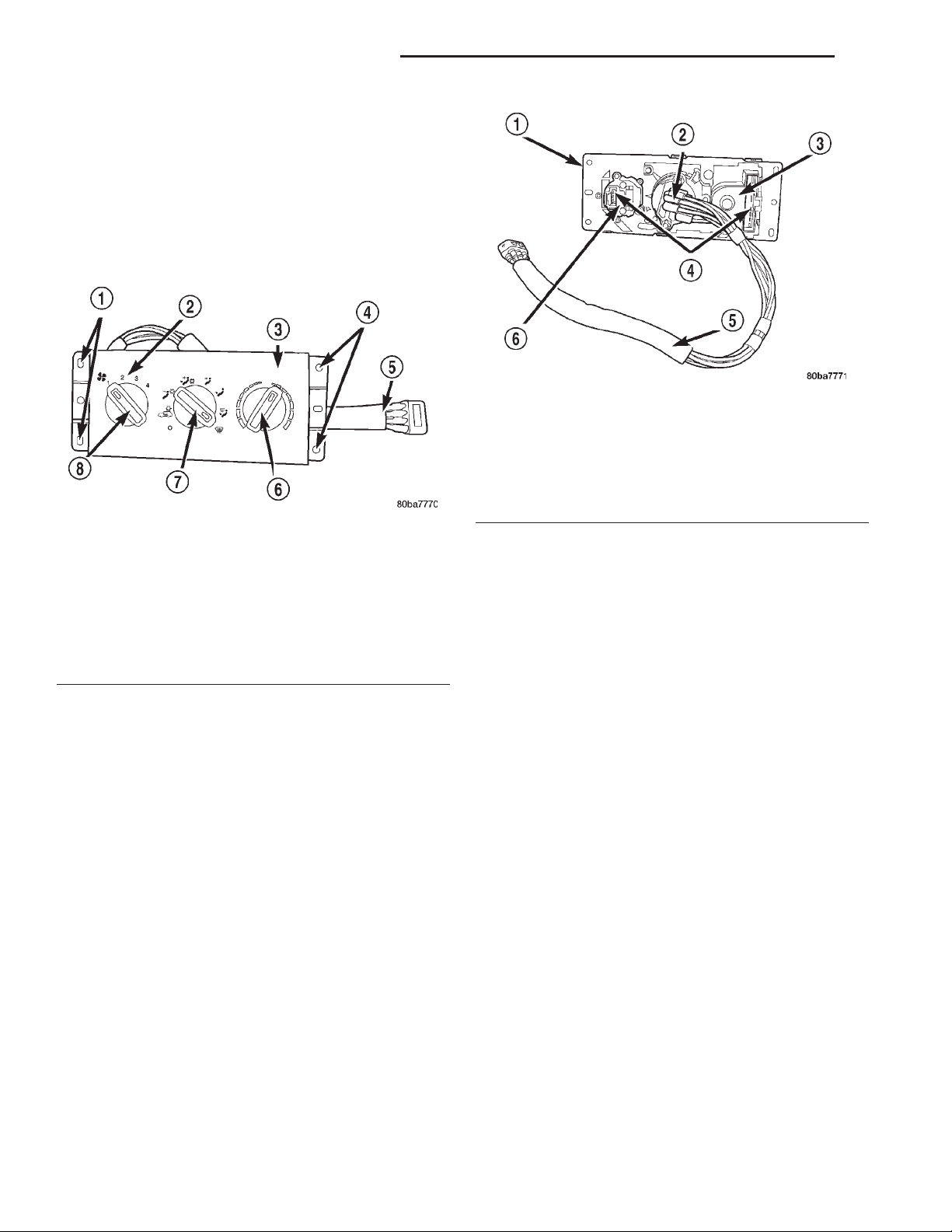
24 - 36 HEATING AND AIR CONDITIONING XJ
REMOVAL AND INSTALLATION (Continued)
(4) Remove the center bezel from the instrument
panel. Refer to Instrument Panel Center Bezel in
Group 8E - Instrument Panel Systems for the procedures.
(5) Release the vacuum harness push-in retainer
from the instrument panel directly beneath the heater-A/C control.
(6) Remove the four screws that secure the heaterA/C control to the instrument panel (Fig. 37).
Fig. 38 Heater-A/C Control Connections
1 – HEATER-A/C CONTROL HEAD
2 – MODE SELECT CONTROL
3 – BLOWER SPEED CONTROL
4 – ELECTRICAL CONNECTORS
5 – VACUUM HARNESS
6 – TEMPERATURE SELECT CONTROL
Fig. 37 Heater-A/C Control Remove/Install
1 – MOUNTING HOLES
2 – CONTROL HEAD
3 – HEATER-A/C CONTROL HEAD
4 – MOUNTING HOLES
5 – VACUUM HARNESS
6 – TEMPERATURE SELECT CONTROL
7 – MODE SELECT CONTROL
8 – BLOWER SPEED CONTROL
(5) Position the heater-A/C control in the instrument panel and secure it with four screws. Tighten
the screws to 2.2 N·m (20 in. lbs.).
(6) Reinstall the center bezel onto the instrument
panel. Refer to Instrument Panel Center Bezel in
Group 8E - Instrument Panel Systems for the procedures.
(7) Connect the battery negative cable.
(7) Pull the heater-A/C control assembly away
from the instrument panel far enough to access the
connections on the back of the control.
(8) Unplug the wire harness connectors from the
back of the heater-A/C control (Fig. 38).
(9) Reach through the instrument panel glove box
opening to guide the heater-A/C control half of the
vacuum harness around any obstacles while pulling
the heater-A/C control out from the front of the
instrument panel.
INSTALLATION
(1) Plug the wire harness connectors into the back
of the heater-A/C control.
(2) Route the vacuum harness through the instrument panel opening and reinstall the vacuum harness push-in retainer.
(3) Reach through the instrument panel glove box
opening to reconnect the two halves of the heater-A/C
vacuum harness connector.
(4) Roll the glove box back up into the instrument
panel. Refer to Glove Box in Group 8E - Instrument
Panel Systems for the procedures.
HEATER-A/C HOUSING
The heater-A/C housing assembly must be removed
from the vehicle and the two halves of the housing
separated for service access of the heater core, evaporator coil, blend-air door, and each of the various
mode control doors.
WARNING: ON VEHICLES EQUIPPED WITH AIRBAGS, REFER TO GROUP 8M - PASSIVE
RESTRAINT SYSTEMS BEFORE ATTEMPTING ANY
STEERING WHEEL, STEERING COLUMN, OR
INSTRUMENT PANEL COMPONENT DIAGNOSIS OR
SERVICE. FAILURE TO TAKE THE PROPER PRECAUTIONS COULD RESULT IN ACCIDENTAL AIRBAG DEPLOYMENT AND POSSIBLE PERSONAL
INJURY.
REMOVAL
(1) Disconnect and isolate the battery negative
cable.
(2) Remove the instrument panel from the vehicle.
Refer to Instrument Panel Assembly in Group 8E Instrument Panel Systems for the procedures.
Page 37
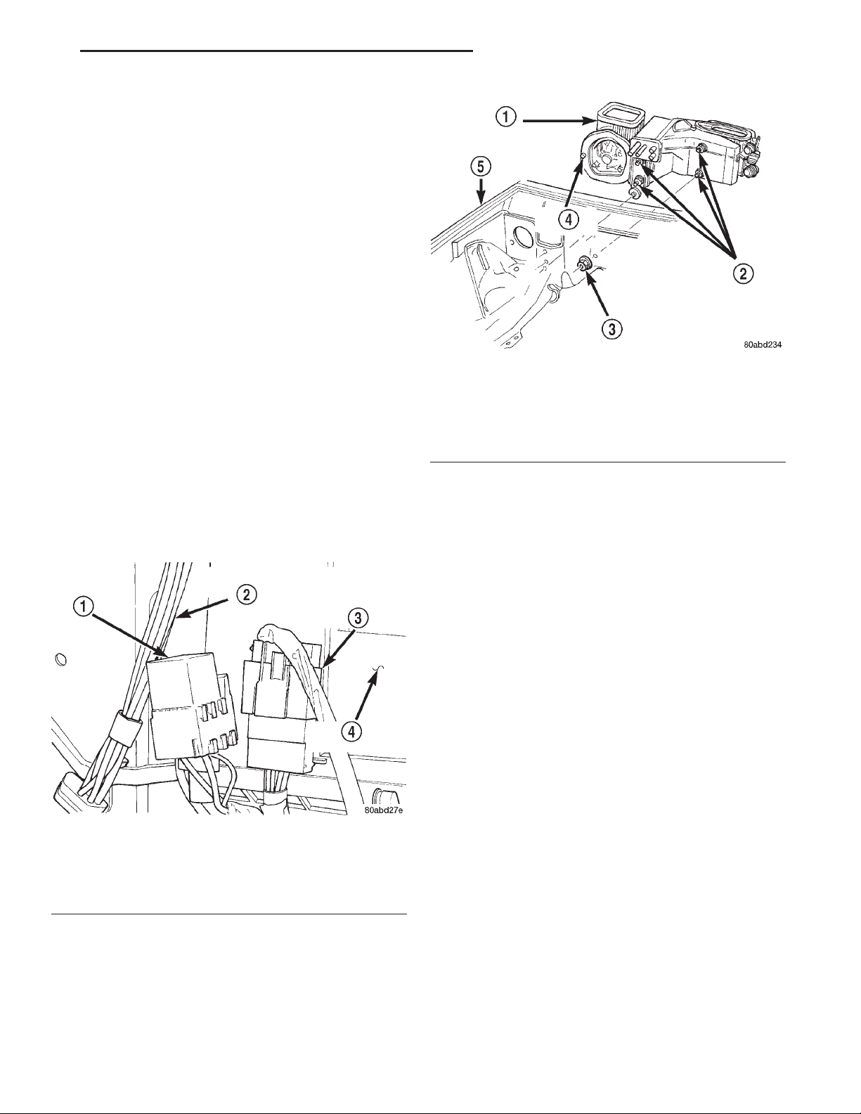
XJ HEATING AND AIR CONDITIONING 24 - 37
REMOVAL AND INSTALLATION (Continued)
(3) If the vehicle is not equipped with air conditioning, go to Step 6. If the vehicle is equipped with
air conditioning, recover the refrigerant from the
refrigerant system. See Refrigerant Recovery in this
group for the procedures.
(4) Disconnect the liquid line refrigerant line fitting from the evaporator inlet tube. See Refrigerant
Line Coupler in this group for the procedures. Install
plugs in, or tape over all of the opened refrigerant
line fittings.
(5) Disconnect the accumulator inlet tube refrigerant line fitting from the evaporator outlet tube. See
Refrigerant Line Coupler in this group for the procedures. Install plugs in, or tape over all of the opened
refrigerant line fittings.
(6) Drain the engine cooling system. Refer to
Group 7 - Cooling System for the procedures.
(7) Disconnect the heater hoses from the heater
core tubes. Refer to Group 7 - Cooling System for the
procedures. Install plugs in, or tape over the opened
heater core tubes.
(8) Unplug the heater-A/C system vacuum supply
line connector from the tee fitting near the heater
core tubes.
(9) Unplug the heater-A/C unit wire harness connector, which is fastened to the heater-A/C housing
next to the blower motor relay (Fig. 39).
Fig. 40 Heater-A/C Housing Remove/Install
1 – HEATER-A/C HOUSING
2 – STUD
3 – NUT
4 – STUD
5 – RIGHT FRONT FENDER
(11) Pull the heater-A/C housing rearward far
enough for the mounting studs and the evaporator
condensate drain tube to clear the dash panel holes.
(12) Remove the heater-A/C housing from the vehicle.
Fig. 39 Heater-A/C Unit Connector
1 – BLOWER MOTOR RELAY
2 – VACUUM HARNESS
3 – HEATER-A/C WIRE HARNESS CONNECTOR
4 – HEATER-A/C HOUSING
(10) Remove the five nuts from the heater-A/C
housing mounting studs on the engine compartment
side of the dash panel (Fig. 40). Remove or reposition
the evaporation canister for additional access, if
required.
DISASSEMBLY
(1) Remove the heater-A/C housing from the vehi-
cle and place it on a work bench.
(2) Unplug the vacuum harness connectors from
the floor door actuator and, if the unit is so equipped,
the recirculation air door actuator.
(3) Disengage the vacuum harness from any routing clips located on the lower half of the heater-A/C
housing.
(4) Disengage the heater-A/C wire harness connector and the blower motor relay wire harness connector push-in retainers from their mounting holes on
the heater-A/C housing.
(5) Remove the blower motor and blower wheel
unit from the heater-A/C housing. See Blower Motor
in this group for the procedures.
(6) Carefully remove the foam seal from the flange
around the blower motor opening in the heater-A/C
housing. If the seal is deformed or damaged, it must
be replaced.
(7) Pull the vacuum supply line and connector
through the foam seal on the heater core and evaporator coil tube mounting flange of the heater-A/C
housing (Fig. 41).
(8) If the unit is equipped with air conditioning,
remove the screw that secures the clamp to the evaporator coil tubes and remove the clamp.
Page 38
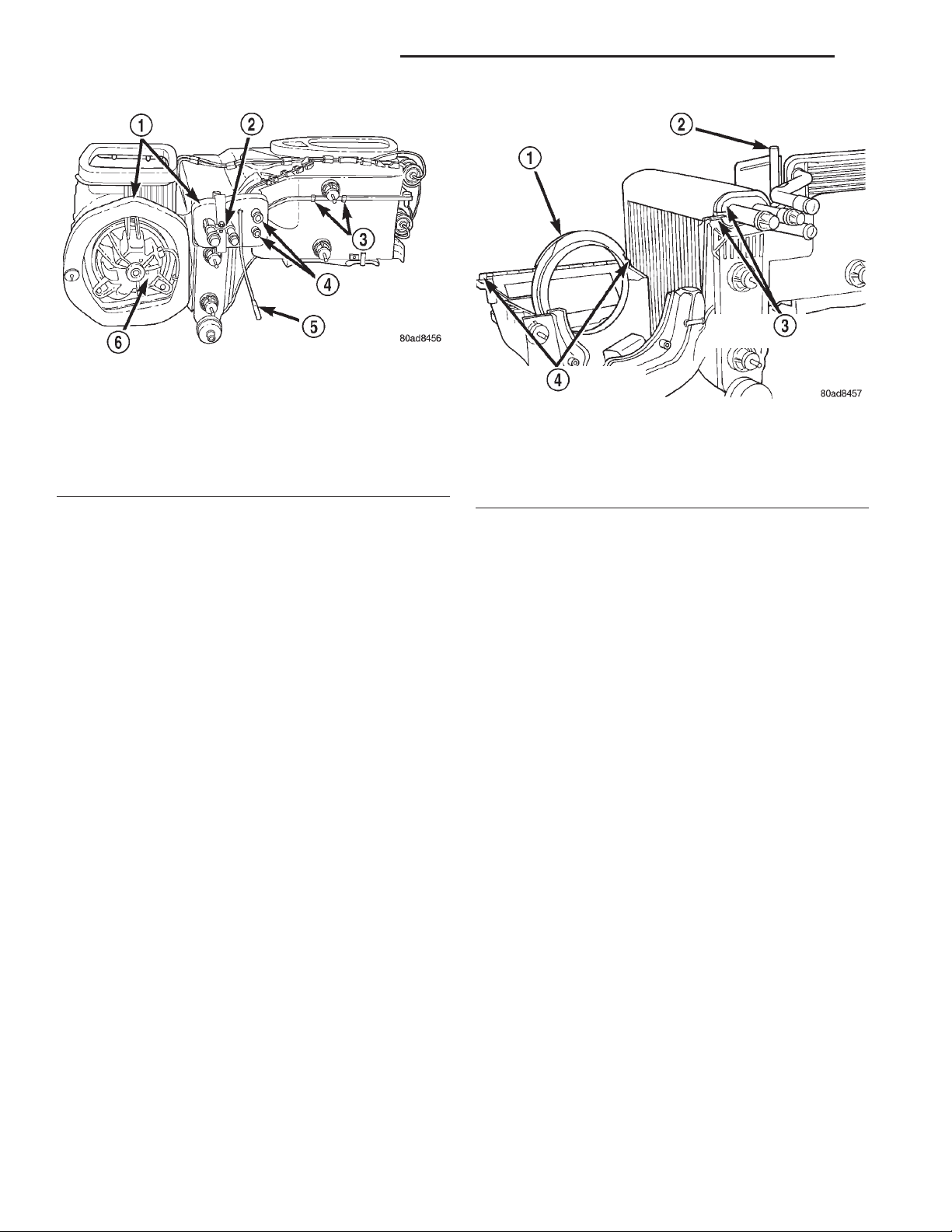
24 - 38 HEATING AND AIR CONDITIONING XJ
REMOVAL AND INSTALLATION (Continued)
Fig. 41 Heater-A/C Housing Disassembly
1 – SEALS
2 – EVAPORATOR TUBE CLAMP
3 – CLIPS
4 – HEATER CORE TUBES
5 – VACUUM SUPPLY LINE
6 – BLOWER MOTOR
1 – BLOWER MOTOR VENTURI RING
2 – BLEND-AIR DOOR PIVOT
3 – EVAPORATOR COIL TUBE RUBBER SEAL
4 – RECIRCULATIONAIR DOOR PIVOTS
Fig. 42 Heater-A/C Housing Assembly
(9) Carefully remove the foam seal from the heater
core and evaporator coil tube mounting flange of the
heater-A/C housing. If the seal is deformed or damaged, it must be replaced.
(10) Use a screwdriver to pry off the two snap clips
that help secure the upper and lower heater-A/C
housing halves to each other.
(11) Remove the 14 screws that secure the upper
and lower heater-A/C housing halves to each other.
(12) Carefully separate the upper heater-A/C housing half from the lower half.
ASSEMBLY
(1) Assemble the upper heater-A/C housing half to
the lower half. During assembly, be certain of the following:
(a) That each of the mode door pivot shaft ends
is properly engaged in its pivot hole (Fig. 42).
(b) That the blower motor venturi ring is prop-
erly indexed and installed.
(c) If the unit is equipped with air conditioning,
that the evaporator coil tube rubber seal is properly positioned in the grooves in both the upper
and lower heater-A/C housing halves.
(2) Install the 14 screws and two snap clips that
secure the upper and lower heater-A/C housing
halves to each other. Tighten the screws to 2.2 N·m
(20 in. lbs.).
(3) Install the blower motor and wheel unit in the
heater-A/C housing. See Blower Motor in this group
for the procedures.
(4) Install the foam seals on the flanges around
the blower motor opening and the heater core and
evaporator coil tube mounting flange of the heaterA/C housing.
(5) Insert the vacuum supply line and connector
through the foam seal on the heater core and evaporator coil tube mounting flange of the heater-A/C
housing.
(6) If the unit is equipped with air conditioning,
reinstall the evaporator coil tube clamp. Tighten the
mounting screw to 2.2 N·m (20 in. lbs.).
(7) Engage the heater-A/C wire harness connector
and blower motor relay wire harness connector
push-in retainers with their mounting holes in the
heater-A/C housing.
(8) Engage the vacuum harness to the routing
clips and plug in the vacuum harness connector at
the floor door actuator and, if the unit is so equipped,
at the recirculation air door actuator.
(9) Install the heater-A/C housing in the vehicle.
INSTALLATION
(1) Position the heater-A/C housing to the dash
panel. Be certain that the evaporator condensate
drain tube and the housing mounting studs are
inserted into their correct mounting holes.
(2) Install and tighten the five nuts onto the heater-A/C housing mounting studs on the engine compartment side of the dash panel. Tighten the nuts to
6.2 N·m (55 in. lbs.).
(3) If the evaporation canister was repositioned
during the removal procedure, reinstall it to its
proper position.
(4) Connect the heater-A/C system vacuum supply
line connector to the tee fitting near the heater core
tubes.
(5) Unplug or remove the tape from the heater
core tubes. Connect the heater hoses to the heater
Page 39

XJ HEATING AND AIR CONDITIONING 24 - 39
REMOVAL AND INSTALLATION (Continued)
core tubes and fill the engine cooling system. Refer to
Group 7 - Cooling System for the procedures.
(6) If the vehicle is not equipped with air conditioning, go to Step 10. If the vehicle is equipped with
air conditioning, unplug or remove the tape from the
accumulator inlet tube and the evaporator outlet
tube fittings. Connect the accumulator inlet tube coupler to the evaporator outlet tube. See Refrigerant
Line Coupler in this group for the procedures.
(7) Unplug or remove the tape from the liquid line
and the evaporator inlet tube fittings. Connect the
liquid line coupler to the evaporator inlet tube. See
Refrigerant Line Coupler in this group for the procedures.
(8) Evacuate the refrigerant system. See Refrigerant System Evacuate in this group for the procedures.
(9) Charge the refrigerant system. See Refrigerant
System Charge in this group for the procedures.
(10) Install the instrument panel in the vehicle.
Refer to Instrument Panel Assembly in Group 8E Instrument Panel Systems for the procedures.
(11) Connect the battery negative cable.
(12) Start the engine and check for proper operation of the heating and air conditioning systems.
HEATER-A/C HOUSING DOOR
1 – BLEND-AIR DOOR
2 – EVAPORATOR COIL
3 – PIVOT HOLE
4 – HEATER CORE
(3) Insert a screwdriver into the latch hole (Fig.
44) of the panel/demist door pivot shaft to release the
latch of the panel/demist door lever, and pull the
lever out of the pivot shaft from the outside of the
upper half of the heater-A/C housing.
Fig. 43 Blend-Air Door
WARNING: ON VEHICLES EQUIPPED WITH AIRBAGS, REFER TO GROUP 8M - PASSIVE
RESTRAINT SYSTEMS BEFORE ATTEMPTING ANY
STEERING WHEEL, STEERING COLUMN, OR
INSTRUMENT PANEL COMPONENT DIAGNOSIS OR
SERVICE. FAILURE TO TAKE THE PROPER PRECAUTIONS COULD RESULT IN ACCIDENTAL AIRBAG DEPLOYMENT AND POSSIBLE PERSONAL
INJURY.
BLEND-AIR DOOR
(1) Remove and disassemble the heater-A/C housing. See Heater-A/C Housing in this group for the
procedures.
(2) Lift the blend-air door pivot shaft out of the
pivot hole in the bottom of the lower half of the heater-A/C housing (Fig. 43).
(3) Reverse the removal procedures to install.
PANEL/DEMIST DOOR AND LEVER
(1) Remove and disassemble the heater-A/C housing. See Heater-A/C Housing in this group for the
procedures.
(2) Remove the defrost and panel/demist door vacuum actuators from the heater-A/C housing. See
Mode Door Vacuum Actuator in this group for the
procedures.
Fig. 44 Mode Door Lever Remove/Install - Typical
1 – DOOR PIVOT SHAFT
2 – LATCH HOLE
3 – CRANK ARM LATCH
4 – FLAT BLADE PRY TOOL
(4) Reach inside the upper half of the heater-A/C
housing and carefully flex the panel/defrost door (Fig.
45) enough so that the door pivot clears the pivot
hole in the housing.
(5) Remove the panel/demist door from the heater-
A/C housing.
(6) Reverse the removal procedures to install.
Page 40
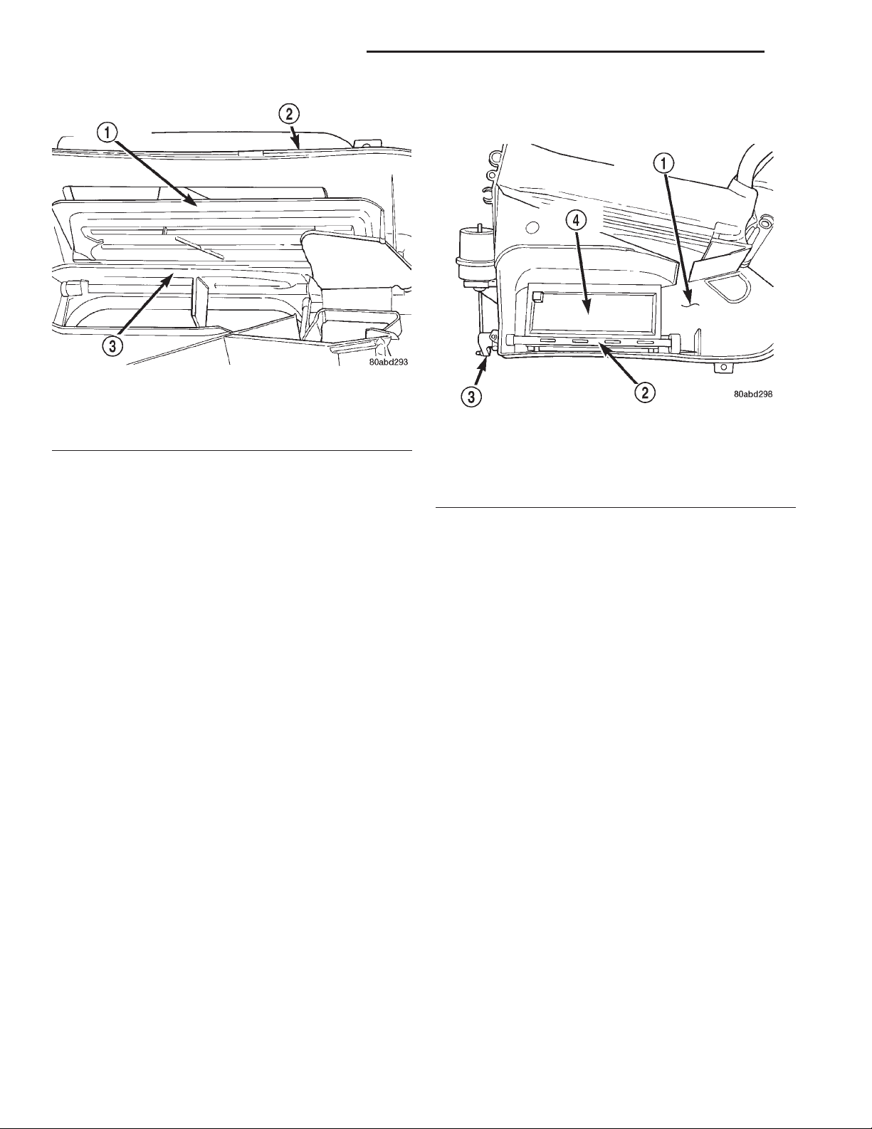
24 - 40 HEATING AND AIR CONDITIONING XJ
REMOVAL AND INSTALLATION (Continued)
enough so that the door pivot clears the pivot hole in
the housing.
Fig. 45 Panel/Demist and Defrost Doors
1 – PANEL/DEMIST DOOR
2 – UPPER HEATER-A/C HOUSING
3 – DEFROST DOOR
DEFROST DOOR AND LEVER
(1) Remove and disassemble the heater-A/C housing. See Heater-A/C Housing in this group for the
procedures.
(2) Remove the panel/demist door and lever from
the upper heater-A/C housing. See Panel/Demist
Door and Lever in this group for the procedures.
(3) Insert a screwdriver into the latch hole (Fig.
44) of the defrost door pivot shaft to release the latch
of the defrost door lever, and pull the lever out of the
pivot shaft from the outside of the upper half of the
heater-A/C housing.
(4) Reach inside the upper half of the heater-A/C
housing and carefully flex the defrost door (Fig. 45)
enough so that the door pivot clears the pivot hole in
the housing.
(5) Remove the defrost door from the heater-A/C
housing.
(6) Reverse the removal procedures to install.
FLOOR DOOR AND LEVER
(1) Remove and disassemble the heater-A/C housing. See Heater-A/C Housing in this group for the
procedures.
(2) Remove the floor door vacuum actuator from
the lower heater-A/C housing. See Mode Door Vacuum Actuator in this group for the procedures.
(3) Insert a screwdriver into the latch hole (Fig.
44) of the floor door pivot shaft to release the latch of
the floor door lever, and pull the lever out of the
pivot shaft from the outside of the lower half of the
heater-A/C housing.
(4) Reach inside the lower half of the heater-A/C
housing and carefully flex the floor door (Fig. 46)
1 – LOWER HEATER-A/C HOUSING
2 – PIVOT SHAFT
3 – CRANK ARM
4 – FLOOR DOOR
(5) Remove the floor door from the heater-A/C
housing.
(6) Reverse the removal procedures to install.
RECIRCULATION AIR DOOR
A recirculation air door and vacuum actuator are
used only on models with the optional air conditioning system.
(1) Remove and disassemble the heater-A/C housing. See Heater-A/C Housing in this group for the
procedures.
(2) Remove the recirculation air door vacuum
actuator from the lower heater-A/C housing. See
Mode Door Vacuum Actuator in this group for the
procedures.
(3) Reach inside the lower half of the heater-A/C
housing and lift the bottom edge of the recirculation
air door upwards (Fig. 47).
(4) Guide the recirculation air door lever through
the air intake grille of the heater-A/C housing while
removing the door from the housing.
(5) Reverse the removal procedures to install.
Fig. 46 Floor Door
Page 41
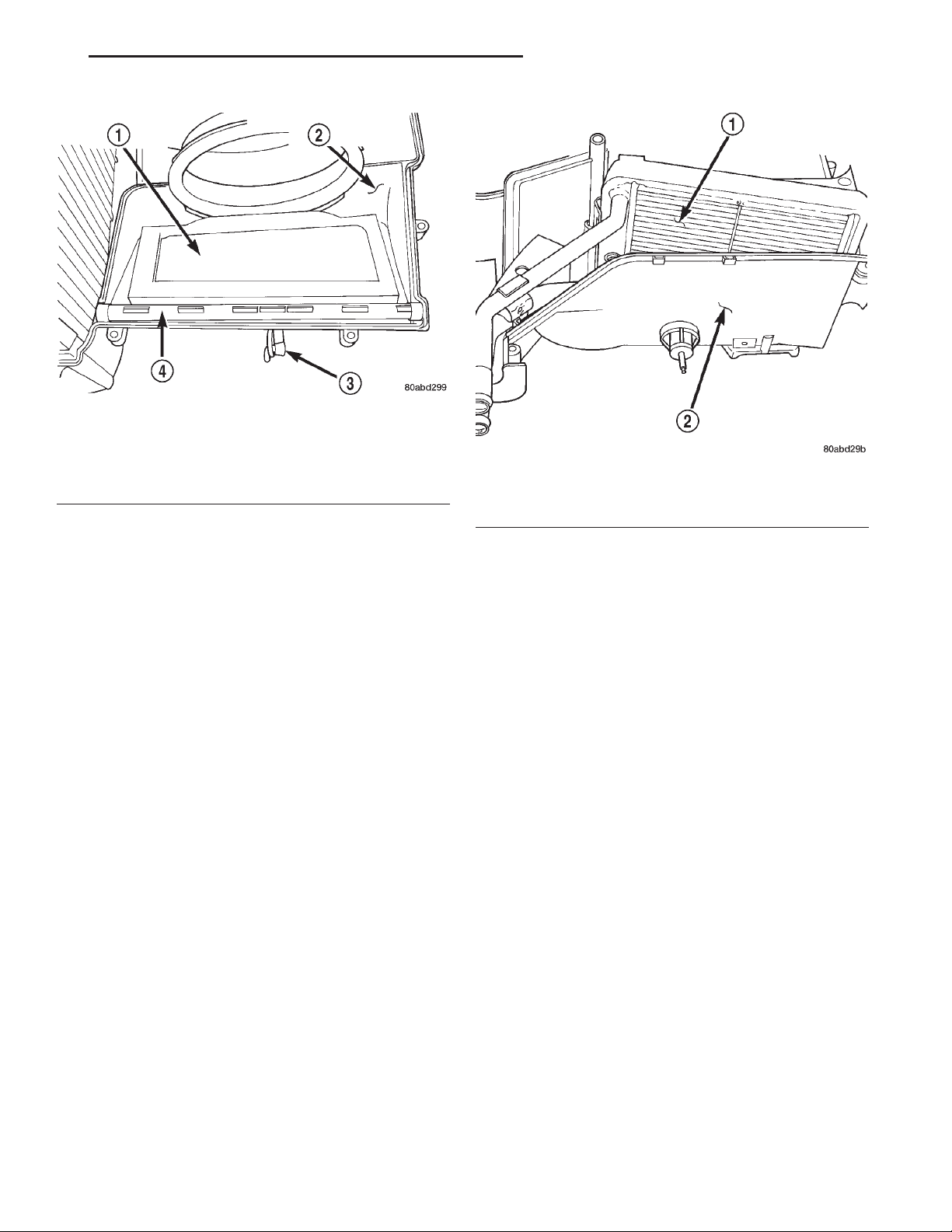
XJ HEATING AND AIR CONDITIONING 24 - 41
REMOVAL AND INSTALLATION (Continued)
Fig. 47 Recirculation Air Door
1 – RECIRCULATIONAIR DOOR
2 – LOWER HEATER-A/C HOUSING
3 – LEVER
4 – PIVOT SHAFT
1 – HEATER CORE
2 – LOWER HEATER-A/C HOUSING
Fig. 48 Heater Core Remove/Install
HEATER CORE
that each of the refrigerant system connections is
WARNING: ON VEHICLES EQUIPPED WITH AIRBAGS, REFER TO GROUP 8M - PASSIVE
RESTRAINT SYSTEMS BEFORE ATTEMPTING ANY
STEERING WHEEL, STEERING COLUMN, OR
INSTRUMENT PANEL COMPONENT DIAGNOSIS OR
SERVICE. FAILURE TO TAKE THE PROPER PRECAUTIONS COULD RESULT IN ACCIDENTAL AIRBAG DEPLOYMENT AND POSSIBLE PERSONAL
INJURY.
pressure-tight and leak free. It is a good practice to
inspect all flexible hose refrigerant lines at least once
a year to make sure they are in good condition and
properly routed.
WARNING: REVIEW THE WARNINGS AND CAUTIONS IN THE FRONT OF THIS GROUP BEFORE
PERFORMING THE FOLLOWING OPERATION.
(1) Remove and disassemble the heater-A/C housing. See Heater-A/C Housing in this group for the
procedures.
(2) Lift the heater core out of the lower half of the
heater-A/C housing (Fig. 48).
(3) Reverse the removal procedures to install. Be
certain that the heater core foam insulator is reinstalled.
LIQUID LINE
Any kinks or sharp bends in the refrigerant plumbing will reduce the capacity of the entire air conditioning system. Kinks and sharp bends reduce the
flow of refrigerant in the system. A good rule for the
flexible hose refrigerant lines is to keep the radius of
all bends at least ten times the diameter of the hose.
In addition, the flexible hose refrigerant lines should
be routed so they are at least 80 millimeters (3
inches) from the exhaust manifold.
High pressures are produced in the refrigerant system when the air conditioning compressor is operating. Extreme care must be exercised to make sure
REMOVAL
(1) Disconnect and isolate the battery negative
cable.
(2) Recover the refrigerant from the refrigerant
system. See Refrigerant Recovery in this group for
the procedures.
(3) Disconnect the liquid line refrigerant line couplers at the evaporator inlet and the condenser outlet
(Fig. 49). See Refrigerant Line Coupler in this group
for the procedures. Install plugs in, or tape over all of
the opened refrigerant line fittings.
(4) Remove the liquid line from the vehicle.
INSTALLATION
(1) Remove the tape or plugs from the refrigerant
line fittings on the liquid line, the evaporator inlet
and the condenser outlet. Connect the liquid line to
the evaporator inlet and condenser outlet refrigerant
line couplers. See Refrigerant Line Coupler in this
group for the procedures.
(2) Connect the battery negative cable.
Page 42
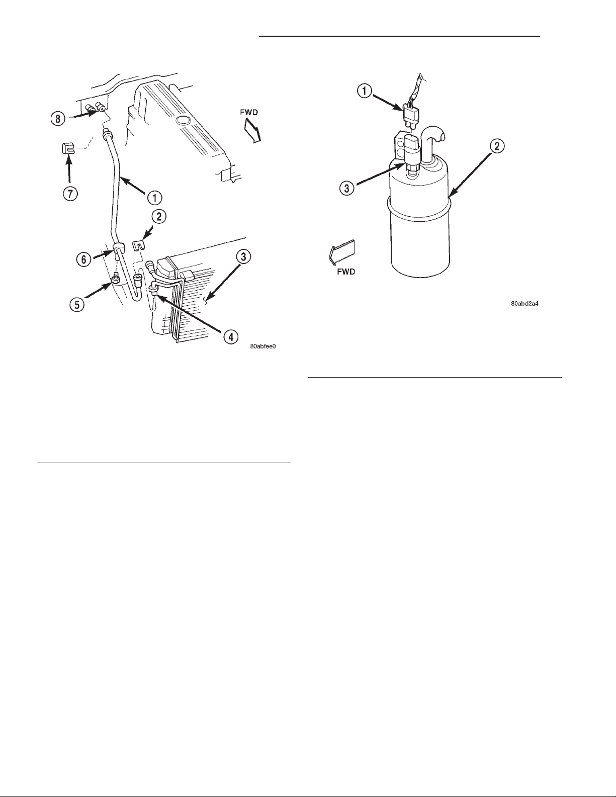
24 - 42 HEATING AND AIR CONDITIONING XJ
REMOVAL AND INSTALLATION (Continued)
Fig. 50 Low Pressure Cycling Clutch Switch
Remove/Install - Typical
1 – WIRE HARNESS CONNECTOR
Fig. 49 Liquid Line Remove/Install
1 – LIQUID LINE WITH ORIFICE TUBE
2 – CLIP
3 – CONDENSER
4 – OUTLET TUBE
5 – STUD
6 – CLIP
7 – CLIP
8 – EVAPORATOR INLET
(3) Evacuate the refrigerant system. See Refrigerant System Evacuate in this group for the procedures.
(4) Charge the refrigerant system. See Refrigerant
System Charge in this group for the procedures.
2 – ACCUMULATOR
3 – LOW PRESSURE CYCLING CLUTCH SWITCH
special material for the R-134a system. Use only
refrigerant oil of the type recommended for the compressor in the vehicle.
(2) Install and tighten the low pressure cycling
clutch switch on the accumulator fitting. The switch
should be hand-tightened onto the accumulator fitting.
(3) Plug the wire harness connector into the low
pressure cycling clutch switch.
(4) Connect the battery negative cable.
KICK COVER
LOW PRESSURE CYCLING CLUTCH SWITCH
REMOVAL
(1) Disconnect and isolate the battery negative
cable.
(2) Unplug the wire harness connector from the
low pressure cycling clutch switch on the top of the
accumulator (Fig. 50).
(3) Unscrew the low pressure cycling clutch switch
from the fitting on the top of the accumulator.
(4) Remove the O-ring seal from the accumulator
fitting and discard.
INSTALLATION
(1) Lubricate a new O-ring seal with clean refrigerant oil and install it on the accumulator fitting.
Use only the specified O-rings as they are made of a
WARNING: ON VEHICLES EQUIPPED WITH AIRBAGS, REFER TO GROUP 8M - PASSIVE
RESTRAINT SYSTEMS BEFORE ATTEMPTING ANY
STEERING WHEEL, STEERING COLUMN, OR
INSTRUMENT PANEL COMPONENT DIAGNOSIS OR
SERVICE. FAILURE TO TAKE THE PROPER PRECAUTIONS COULD RESULT IN ACCIDENTAL AIRBAG DEPLOYMENT AND POSSIBLE PERSONAL
INJURY.
REMOVAL
(1) Disconnect and isolate the battery negative
cable.
(2) Loosen the two screws that secure the upper
half of the kick cover to the heater-A/C housing
Page 43
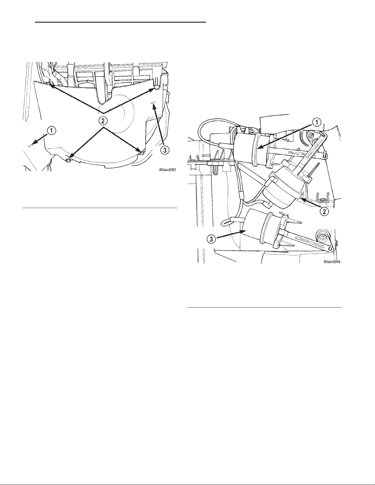
XJ HEATING AND AIR CONDITIONING 24 - 43
REMOVAL AND INSTALLATION (Continued)
under the passenger side end of the instrument panel
(Fig. 51).
Fig. 51 Kick Cover Remove/Install
1 – HEATER-A/C HOUSING
2 – MOUNTING SCREWS
3 – KICK COVER
(3) Remove the two screws that secure the lower
half of the kick cover to the heater-A/C housing.
(4) Pull the kick cover down towards the floor
panel to disengage the slotted upper mounting tabs
from under the two loosened heater-A/C housing
screws.
(5) Remove the kick cover from the heater-A/C
housing.
INSTALLATION
(1) Position the slotted upper kick cover mounting
tabs under the heads of the two loosened heater-A/C
housing screws. Tighten the screws to 2.2 N·m (20 in.
lbs.).
(2) Install the two screws that secure the lower
kick cover to the heater-A/C housing. Tighten the
screws to 2.2 N·m (20 in. lbs.).
(3) Connect the battery negative cable.
MODE DOOR VACUUM ACTUATOR
WARNING: ON VEHICLES EQUIPPED WITH AIRBAGS, REFER TO GROUP 8M - PASSIVE
RESTRAINT SYSTEMS BEFORE ATTEMPTING ANY
STEERING WHEEL, STEERING COLUMN, OR
INSTRUMENT PANEL COMPONENT DIAGNOSIS OR
SERVICE. FAILURE TO TAKE THE PROPER PRECAUTIONS COULD RESULT IN ACCIDENTAL AIRBAG DEPLOYMENT AND POSSIBLE PERSONAL
INJURY.
DEFROST DOOR ACTUATOR
(1) Disconnect and isolate the battery negative
cable.
(2) Remove the instrument panel assembly from
the vehicle. Refer to Instrument Panel Assembly in
Group 8E - Instrument Panel Systems for the procedures.
(3) Unplug the two vacuum harness connectors
from the defrost door actuator (Fig. 52).
Fig. 52 Defrost, Floor, and Panel/Demist Door
Vacuum Actuators
1 – PANEL/DEMIST DOOR ACTUATOR
2 – DEFROST DOOR ACTUATOR
3 – FLOOR DOOR ACTUATOR
(4) Insert a trim stick or another suitable wide
flat-bladed tool into the latch hole on the heater-A/C
housing actuator mount (Fig. 53). Gently pry the
actuator latch while pulling firmly outwards on the
actuator to remove the actuator from the mount.
(5) Rotate and tilt the vacuum actuator as
required to disengage the hole on the end of the
actuator link from the hooked pin on the end of the
defrost door lever.
(6) Remove the defrost door vacuum actuator from
the vehicle.
(7) Reverse the removal procedures to install.
FLOOR DOOR ACTUATOR
(1) Disconnect and isolate the battery negative
cable.
(2) Remove the instrument panel assembly from
the vehicle. Refer to Instrument Panel Assembly in
Page 44
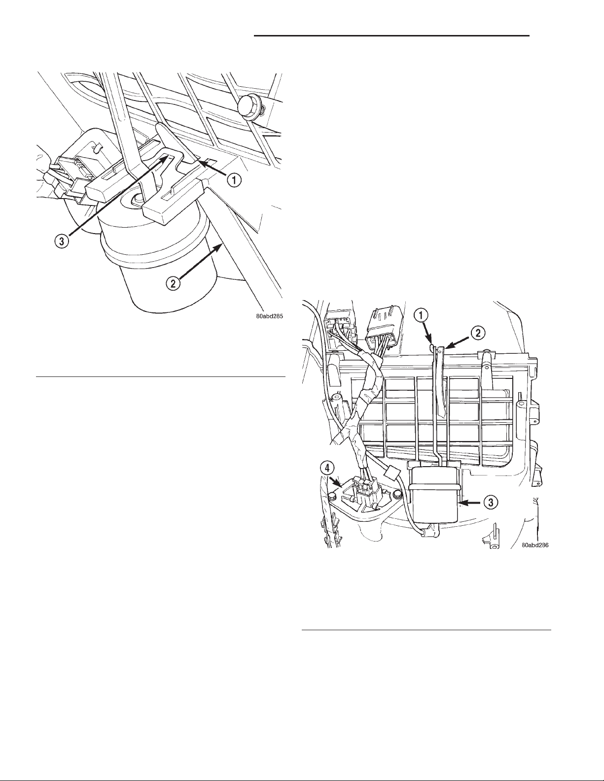
24 - 44 HEATING AND AIR CONDITIONING XJ
REMOVAL AND INSTALLATION (Continued)
(4) Rotate and tilt the vacuum actuator as
required to disengage the hole on the end of the
actuator link from the hooked pin on the end of the
panel/demist door lever.
(5) Remove the panel/demist door vacuum actuator
from the vehicle.
(6) Reverse the removal procedures to install.
RECIRCULATION AIR DOOR ACTUATOR
A recirculation air door and vacuum actuator are
used only on models with the optional air conditioning system.
(1) Disconnect and isolate the battery negative
cable.
(2) Remove the kick cover from the heater-A/C
housing. See Kick Cover in this group for the procedures.
(3) Unplug the vacuum harness connector from the
recirculation air door actuator (Fig. 54).
Fig. 53 Vacuum Actuator Remove/Install - Typical
1 – ACTUATOR MOUNT LATCH HOLE
2 – TRIM STICK
3 – ACTUATOR LATCH
Group 8E - Instrument Panel Systems for the procedures.
(3) Unplug the vacuum harness connector from the
floor door actuator (Fig. 52).
(4) Insert a trim stick or another suitable wide
flat-bladed tool into the latch hole on the heater-A/C
housing actuator mount (Fig. 53). Gently pry the
actuator latch while pulling firmly outwards on the
actuator to remove the actuator from the mount.
(5) Rotate and tilt the vacuum actuator as
required to disengage the hole on the end of the
actuator link from the hooked pin on the end of the
floor door lever.
(6) Remove the floor door vacuum actuator from
the vehicle.
(7) Reverse the removal procedures to install.
PANEL/DEMIST DOOR ACTUATOR
(1) Remove the defrost door actuator from the
heater-A/C housing. See Defrost Door Actuator in
this group for the procedures.
(2) Unplug the vacuum harness connector from the
panel/demist door actuator (Fig. 52).
(3) Insert a trim stick or another suitable wide
flat-bladed tool into the latch hole on the heater-A/C
housing actuator mount (Fig. 53). Gently pry the
actuator latch while pulling firmly outwards on the
actuator to remove the actuator from the mount.
Fig. 54 Recirculation Air Door Vacuum Actuator
Remove/Install
1 – HOOK
2 – LEVER
3 – RECIRCULATIONAIR DOOR ACTUATOR
4 – BLOWER MOTOR RESISTOR
(4) Insert a trim stick or another suitable wide
flat-bladed tool into the latch hole on the heater-A/C
housing actuator mount (Fig. 53). Gently pry the
actuator latch while pulling firmly outwards on the
actuator to remove the actuator from the mount.
(5) Rotate and tilt the vacuum actuator as
required to disengage the hole on the end of the
Page 45
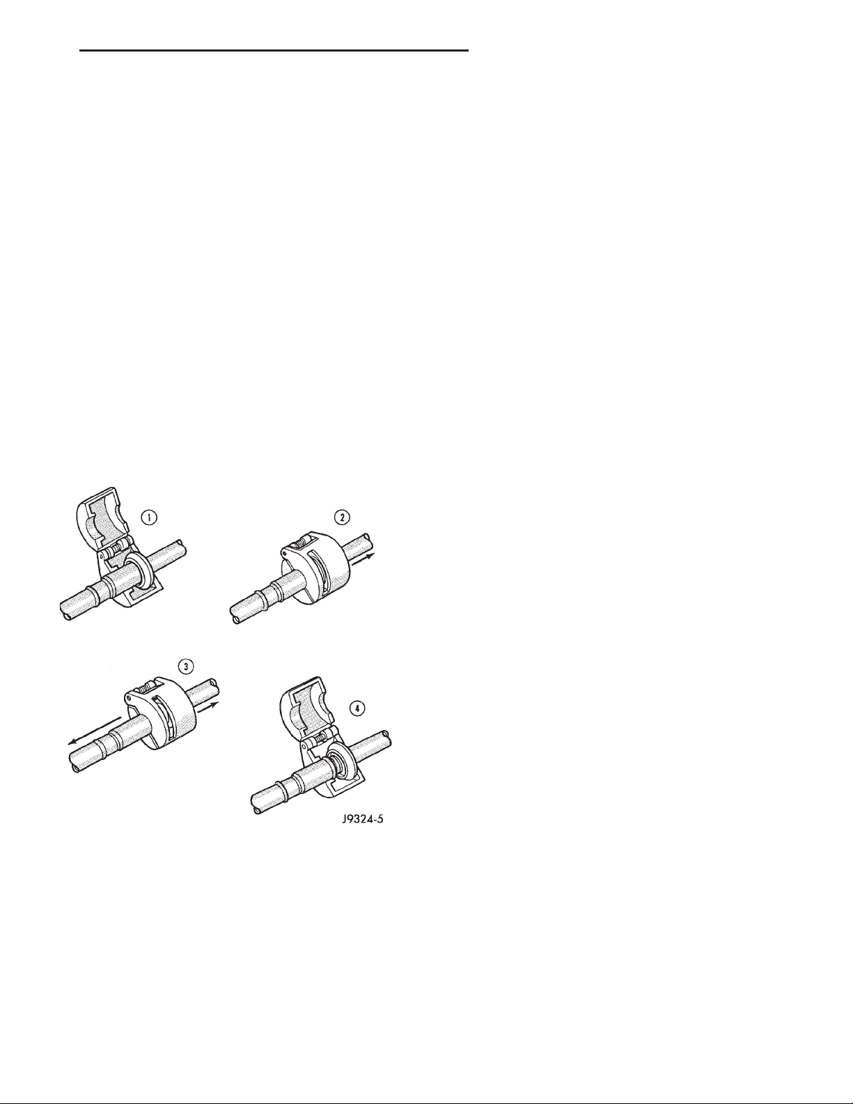
XJ HEATING AND AIR CONDITIONING 24 - 45
REMOVAL AND INSTALLATION (Continued)
actuator link from the hooked pin on the end of the
recirculation air door lever.
(6) Remove the recirculation air door vacuum
actuator from the vehicle.
(7) Reverse the removal procedures to install.
REFRIGERANT LINE COUPLER
WARNING: REVIEW THE WARNINGS AND CAUTIONS IN THE GENERAL INFORMATION SECTION
NEAR THE FRONT OF THIS GROUP BEFORE PERFORMING THE FOLLOWING OPERATION.
REMOVAL
(1) Recover the refrigerant from the refrigerant
system. See Refrigerant Recovery in the Service Procedures section of this group.
(2) Remove the secondary clip from the spring-lock
coupler.
(3) Fit the proper size A/C line disconnect tool
(Special Tool Kit 7193) over the spring-lock coupler
cage (Fig. 55).
spring and cage on the male fitting within the disconnect tool.
NOTE: The garter spring may not release if the A/C
line disconnect tool is cocked while pushing it into
the coupler cage opening.
(6) Open and remove the A/C line disconnect tool
from the disconnected spring-lock coupler.
(7) Complete the separation of the two halves of
the coupler fitting.
INSTALLATION
(1) Check to ensure that the garter spring is
located within the cage of the male coupler fitting,
and that the garter spring is not damaged.
(a) If the garter spring is missing, install a new
spring by pushing it into the coupler cage opening.
(b) If the garter spring is damaged, remove it
from the coupler cage with a small wire hook (DO
NOT use a screwdriver) and install a new garter
spring.
(2) Clean any dirt or foreign material from both
halves of the coupler fitting.
(3) Install new O-rings on the male half of the cou-
pler fitting.
Fig. 55 Refrigerant Line Spring-Lock Coupler
Disconnect
(4) Close the two halves of the A/C line disconnect
tool around the spring-lock coupler.
(5) Push the A/C line disconnect tool into the open
side of the coupler cage to expand the garter spring.
Once the garter spring is expanded and while still
pushing the disconnect tool into the open side of the
coupler cage, pull on the refrigerant line attached to
the female half of the coupler fitting until the flange
on the female fitting is separated from the garter
CAUTION: Use only the specified O-rings as they
are made of a special material for the R-134a system. The use of any other O-rings may allow the
connection to leak intermittently during vehicle
operation.
(4) Lubricate the male fitting and O-rings, and the
inside of the female fitting with clean R-134a refrigerant oil. Use only refrigerant oil of the type recommended for the compressor in the vehicle.
(5) Fit the female half of the coupler fitting over
the male half of the fitting.
(6) Push together firmly on the two halves of the
coupler fitting until the garter spring in the cage on
the male half of the fitting snaps over the flanged
end on the female half of the fitting.
(7) Ensure that the spring-lock coupler is fully
engaged by trying to separate the two coupler halves.
This is done by pulling the refrigerant lines on either
side of the coupler away from each other.
(8) Reinstall the secondary clip over the springlock coupler cage.
SUCTION AND DISCHARGE LINE
Any kinks or sharp bends in the refrigerant plumbing will reduce the capacity of the entire air conditioning system. Kinks and sharp bends reduce the
flow of refrigerant in the system. A good rule for the
flexible hose refrigerant lines is to keep the radius of
all bends at least ten times the diameter of the hose.
Page 46
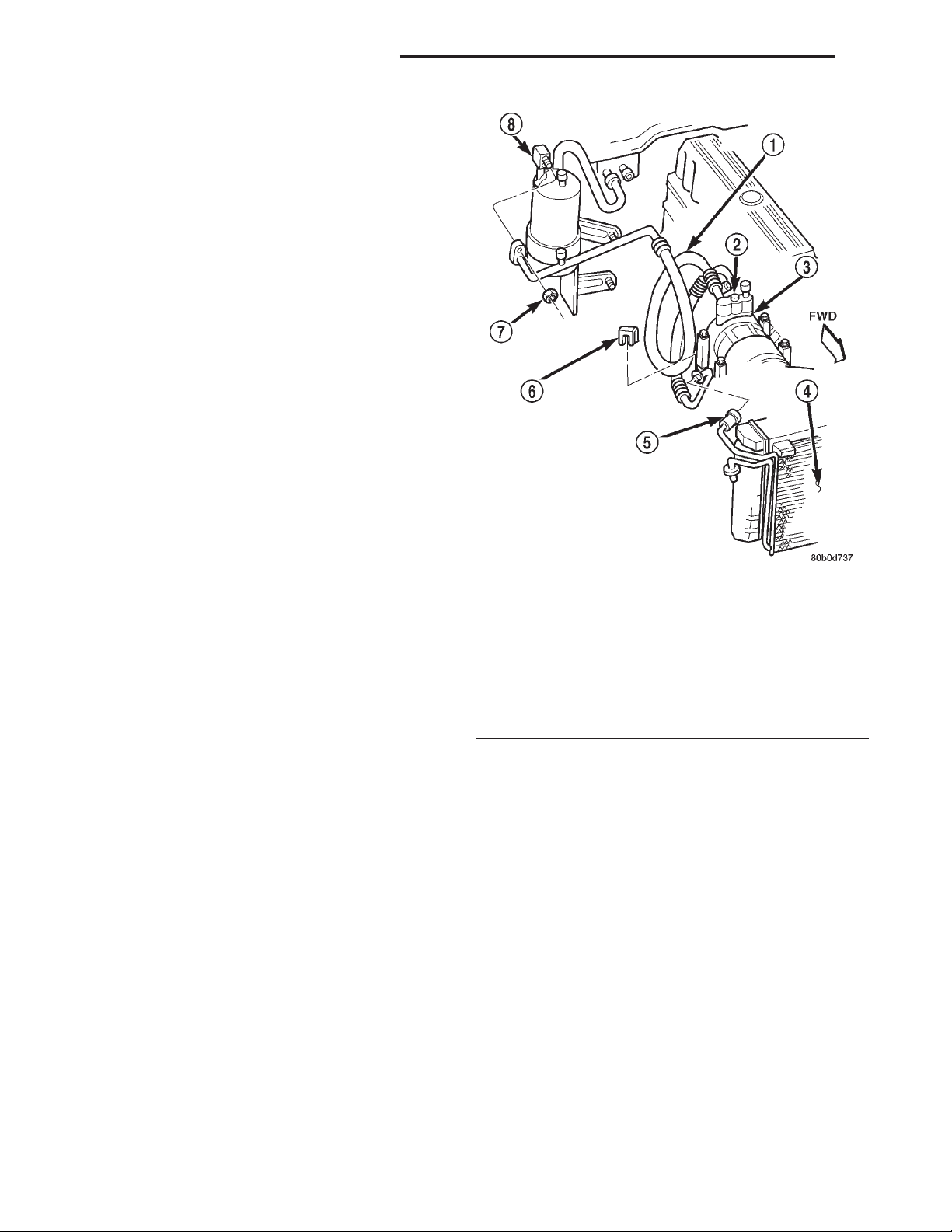
24 - 46 HEATING AND AIR CONDITIONING XJ
REMOVAL AND INSTALLATION (Continued)
In addition, the flexible hose refrigerant lines should
be routed so they are at least 80 millimeters (3
inches) from the exhaust manifold.
High pressures are produced in the refrigerant system when the air conditioning compressor is operating. Extreme care must be exercised to make sure
that each of the refrigerant system connections is
pressure-tight and leak free. It is a good practice to
inspect all flexible hose refrigerant lines at least once
a year to make sure they are in good condition and
properly routed.
WARNING: REVIEW THE WARNINGS AND CAUTIONS IN THE FRONT OF THIS GROUP BEFORE
PERFORMING THE FOLLOWING OPERATION.
REMOVAL
(1) Disconnect and isolate the battery negative
cable.
(2) Recover the refrigerant from the refrigerant
system. See Refrigerant Recovery in this group for
the procedures.
(3) Unplug the wire harness connector from the
high pressure cut-off switch.
(4) Disconnect the discharge line refrigerant line
fitting from the condenser inlet tube (Fig. 56). See
Refrigerant Line Coupler in this group for the procedures. Install plugs in, or tape over all of the opened
refrigerant line fittings.
(5) Remove the nut that secures the suction line
block fitting to the accumulator outlet. Install plugs
in, or tape over all of the opened refrigerant line fittings.
(6) Remove the screw that secures the suction and
discharge line manifold to the compressor. Install
plugs in, or tape over all of the opened refrigerant
line fittings.
(7) Remove the suction and discharge line assembly from the vehicle.
INSTALLATION
(1) Remove the tape or plugs from the suction and
discharge line manifold and the compressor. Install
the suction and discharge line manifold to the compressor. Tighten the mounting screw to 28 N·m (250
in. lbs.).
(2) Remove the tape or plugs from the suction line
and the accumulator outlet block fittings. Install the
suction line to the accumulator outlet and tighten the
mounting nut to 9 N·m (80 in. lbs.).
(3) Remove the tape or plugs from the refrigerant
line fittings on the discharge line and the condenser
inlet tube. Connect the discharge line refrigerant line
coupler to the condenser inlet tube. See Refrigerant
Line Coupler in this group for the procedures.
1 – SUCTION AND DISCHARGE LINE
2 – SCREW
3 – COMPRESSOR
4 – CONDENSER
5 – INLET
6 – CLIP
7 – HEX NUT
8 – ACCUMULATOR
(4) Plug in the wire harness connector to the high
pressure cut-off switch.
(5) Connect the battery negative cable.
(6) Evacuate the refrigerant system. See Refrigerant System Evacuate in this group for the procedures.
(7) Charge the refrigerant system. See Refrigerant
System Charge in this group for the procedures.
VACUUM CHECK VALVE
(1) Unplug the heater-A/C vacuum supply line connector at the vacuum check valve (Fig. 57).
(2) Note the orientation of the check valve in the
vacuum supply line for correct reinstallation.
(3) Unplug the vacuum check valve from the vacuum supply line fittings.
(4) Reverse the removal procedures to install.
Fig. 56 Suction and Discharge Line
Page 47
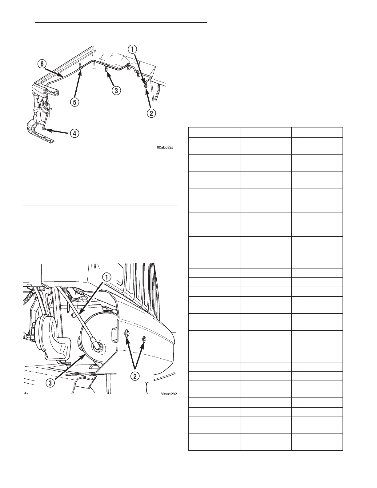
XJ HEATING AND AIR CONDITIONING 24 - 47
REMOVAL AND INSTALLATION (Continued)
(3) Remove the two screws that secure the vacuum
reservoir to the front bumper.
(4) Remove the vacuum reservoir from behind the
front bumper.
(5) Reverse the removal procedures to install.
Tighten the mounting screws to 2.2 N·m (20 in. lbs.).
SPECIFICATIONS
A/C APPLICATION TABLE
Item Description Notes
Vehicle XJ Cherokee/
Laredo
Fig. 57 Vacuum Supply
1 – VACUUM CHECK VALVE
2 – TO ENGINE INTAKE MANIFOLD
3 – TO HEATER-A/C CONTROLS
4 – TO VACUUM RESERVOIR
5 – TO SPEED CONTROL SERVO
6 – VACUUM SUPPLY LINE
VACUUM RESERVOIR
(1) Remove the passenger side bumper end cap
from the front bumper. Refer to Group 23 - Body for
the procedures.
(2) Unplug the vacuum supply line connector from
the vacuum reservoir (Fig. 58).
Fig. 58 Vacuum Reservoir Remove/Install
1 – VACUUM LINE
2 – RESERVOIR SCREWS
3 – VACUUM RESERVOIR
System R134a w/orifice
tube
Compressor Sanden
SP-20 PAG oil
SD7H15
Freeze–up
Control
Low Pressure
cycling cutout
accumulator
mounted
switch
Low psi Control opens < 25 psi
- resets > 43
psi
High psi Control switch - opens
discharge line
> 450-490 psi resets <
270-330 psi
Control Head manual type
Mode Door vacuum
Blend-Air Door electric
Fresh/Recirc
vacuum
door
Blower Motor hardwired to
resistor block
control head
Cooling Fan viscous for
cooling, single
speed electric
for A/C
Clutch
Control relay PCM
Draw 2 - 3.7 amps @
6 0.5V @ 70° F
12V
Gap 0.016” - 0.0319
DRB IIIT
Reads TPS, RPM, A/C
switch test
Actuators clutch and fan
relay
Page 48

 Loading...