

Page 1
XJ TRANSMISSION AND TRANSFER CASE 21 - 1
TRANSMISSION AND TRANSFER CASE
TABLE OF CONTENTS
page page
NV3550 MANUAL TRANSMISSION ............ 1 NV231 TRANSFER CASE .................... 5
NV3550 MANUAL TRANSMISSION
TABLE OF CONTENTS
page page
REMOVAL AND INSTALLATION
TRANSMISSION - 2.5L TURBO DIESEL
ENGINE ...............................1
REMOVAL AND INSTALLATION
TRANSMISSION - 2.5L TURBO DIESEL ENGINE
REMOVAL
1. Disconnect and isolate the negative battery
cable.
2. Remove the floor console, shifter boot and
shifter. Refer to group 23, Body for the procedure.
3. Raise the vehicle on a hoist.
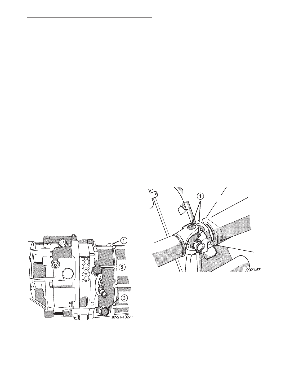
4. Drain the transmission fluid (Fig. 1).
SPECIFICATIONS
TORQUE ................................4
5. Remove exhaust pipe and heat shield.
6. Mark the front and rear propeller shafts for
installation alignment (Fig. 2).
Fig. 2 Marking Propeller Shaft and Axle Yoke
1 – MARK BOTH YOKES FOR ALIGNMENT AT INSTALLATION
Fig. 1 Drain Plug and Backup Light Switch Location
1 – GEAR CASE
2 – BACKUP LIGHT SWITCH
3 – DRAIN PLUG
7. Remove the front propeller shaft.
8. Remove the rear propeller shaft.
9. Remove the transmission skid plate.
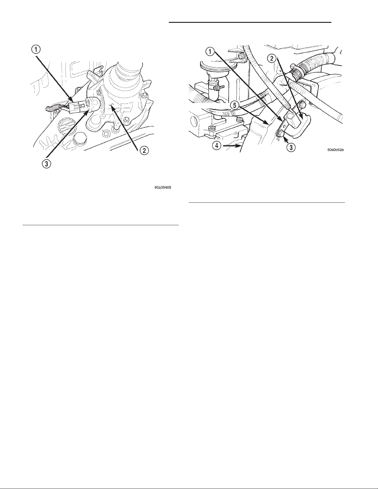
10. Disconnect the transfer case linkage and vehicle speed sensor electrical connector and vent tube
hose (Fig. 3).
11. Support the engine with an adjustable jack
stand.
12. Place a transmission jack under the transmission and secure the transmission with safety chains.
Page 2
21 - 2 TRANSMISSION AND TRANSFER CASE XJ
REMOVAL AND INSTALLATION (Continued)
Fig. 4 Engine Speed Sensor
1 – ENGINE SPEED SENSOR
2 – GROMMET
3 – MOUNTING BOLT(S)
4 – LEFT REAR OF ENGINE
Fig. 3 Vehicle Speed Sensor
1 – SENSOR ELECTRICAL CONNECTOR
2 – 4WD TRANSFER CASE EXTENSION
3 – VEHICLE SPEED SENSOR
13. Remove the rear transmission mount.
14. Remove the rear crossmember.
15. Remove the transfer case assembly. Refer to
Transfer Case removal later in this Group.
16. Lower the engine and transmission no more
than 7.6 cm.
17. Remove the two (2) upper and two (2) mid
clutch housing to engine bolts.
18. Remove the engine speed sensor (crankshaft
position sensor) (Fig. 4).
19. Remove the clutch slave cylinder from the
clutch housing.
20. Remove the lower transmission bolts.
21. Remove the transmission assembly from the
vehicle.
INSTALLATION
1. Mount the transmission on a transmission jack
and secure the transmission with safety chains.
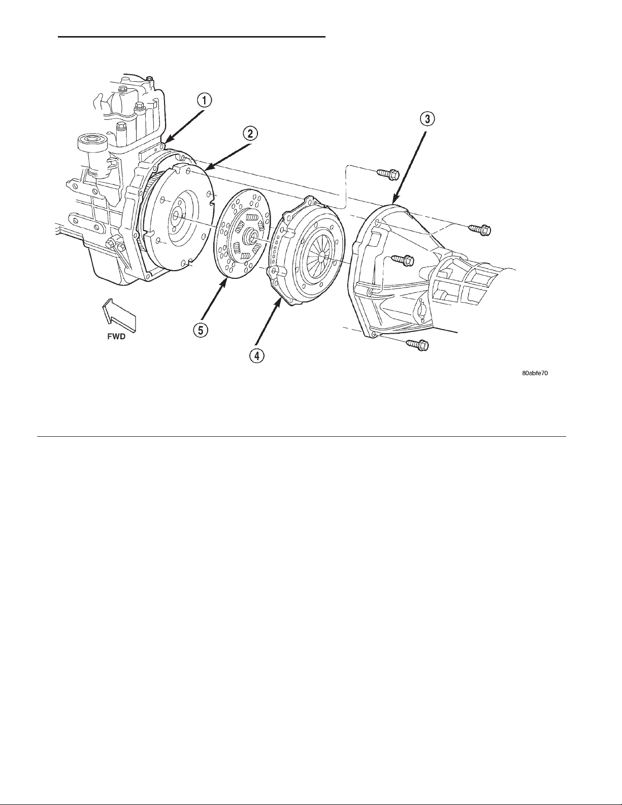
2. Position the transmission in the vehicle (Fig. 5).
3. Install the two (2) lower transmission bolts.
Tighten the bolts to 74.6 N·m.
4. Install the clutch slave cylinder on the clutch
housing.
5. Install the engine speed sensor (crankshaft posi-
tion sensor) on the vehicle (Fig. 4).
5 – TRANSMISSION
6. Install the two (2) upper clutch housing to
engine bolts. Tighten the bolts to 36.6 N·m.
7. Install the two (2) mid clutch housing to engine
bolts. Tighten the bolts to 58.3 N·m.
8. Raise the engine and transmission with the
adjustable jackstand.
9. Install the transfer case assembly. Refer to
Transfer Case installation later in this Group.
10. Install the rear crossmember.
11. Install the rear transmission mount.
12. Connect the transfer case linkage and vehicle
speed sensor electrical connector and vent tube (Fig.
3).
13. Install the transmission skid plate.
14. Install the front and rear propeller shafts in
there original position, using the reference marks
scribed earlier.
15. Install the exhaust pipe and heat shield.
16. Remove the transmission jack.
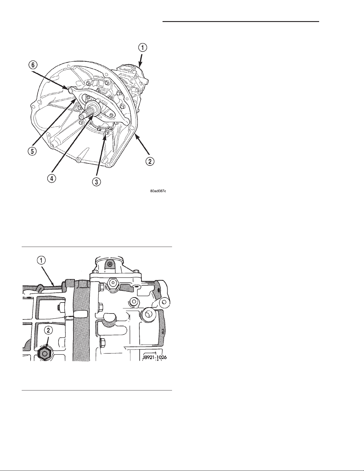
17. Fill the transmission with the proper fluid
(Fig. 7).
18. Remove the adjustable jackstand from under
the engine.
19. Lower the vehicle from the hoist.
20. Install the shifter, shifter boot and floor console.
21. Reconnect the negative battery cable.
22. Using the DRB III Scan Tool clear any DTC’s
and reset customer preferences.
Page 3
XJ TRANSMISSION AND TRANSFER CASE 21 - 3
SPECIFICATIONS (Continued)
Fig. 5 Transmission to Engine Mounting
1 – ENGINE BLOCK
2 – FLYWHEEL
3 – CLUTCH HOUSING AND TRANSMISSION
4 – CLUTCH COVER
5 – CLUTCH DISC
Page 4
21 - 4 TRANSMISSION AND TRANSFER CASE XJ
SPECIFICATIONS (Continued)
SPECIFICATIONS
TORQUE
DESCRIPTION TORQUE
Clutch Housing to Engine Top (2) Bolts . . 36.6 N·m
(27 ft. lbs.)
Clutch Housing to Engine Mid-Point
(2) Bolts ............... 58.3 N·m (43 ft. lbs.)
Clutch Housing to Engine Bottom
(2) Bolts ............... 74.6 N·m (55 ft. lbs.)
Clutch Housing to Transmission bolts . . . 38.0 N·m
(28 ft. lbs.)
Transfer Case to Transmission
Attaching Nuts ........... 35N·m(26ft.lbs.)
Propeller Shaft Bolts ...... 26.5 N·m (19.5 ft. lbs.)
Fig. 6 Clutch Housing to Transmission
1 – TRANSMISSION
2 – CLUTCH HOUSING
3 – CLUTCH HOUSING BOLT
4 – RELEASE BEARING
5 – RELEASE FORK
6 – PIVOT
Fig. 7 Fill Plug Location
1 – GEAR CASE
2 – FILL PLUG
Page 5
XJ TRANSMISSION AND TRANSFER CASE 21 - 5
NV231 TRANSFER CASE
TABLE OF CONTENTS
page page
REMOVAL AND INSTALLATION
TRANSFER CASE .........................5
REMOVAL AND INSTALLATION
TRANSFER CASE
REMOVAL
(1) Shift transfer case into Neutral.
(2) Raise vehicle.
(3) Drain transfer case lubricant.
(4) Mark front and rear propeller shaft yokes for
alignment reference.
(5) Support transmission with jack stand.
(6) Remove rear crossmember and skid plate, if
equipped.
(7) Disconnect and support front/rear propeller
shafts at transfer case.
(8) Disconnect vehicle speed sensor wires.
(9) Disconnect transfer case linkage rod from
range lever.
(10) Disconnect transfer case vent hose (Fig. 1)
and indicator switch harness, if necessary.
(11) Support transfer case with transmission jack.
(12) Secure transfer case to jack with chains.
(13) Remove nuts attaching transfer case to trans-
mission.
(14) Pull transfer case and jack rearward to disen-
gage transfer case.
(15) Remove transfer case from under vehicle.
INSTALLATION
(1) Mount transfer case on a transmission jack.
(2) Secure transfer case to jack with chains.
(3) Position transfer case under vehicle.
(4) Align transfer case and transmission shafts
and install transfer case on transmission.
(5) Install and tighten transfer case attaching nuts
to 35 N·m (Fig. 1).
(6) Connect vehicle speed sensor wires, and vent
hose.
(7) Connect indicator switch harness to transfer
case switch, if necessary. Secure wire harness to clips
on transfer case.
NOTE: Do no reuse bearing straps or bolts. Discard
and replace with new.
SPECIFICATIONS
TORQUE ................................5
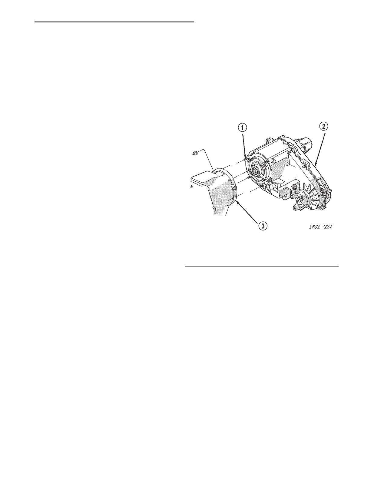
Fig. 1 Transfer Case Mounting
1 – MOUNTING STUDS
2 – TRANSFER CASE
3 – TRANSMISSION
(8) Align and connect propeller shafts. Tighten
shaft attaching bolts to 26.5 N·m torque.
(9) Fill transfer case with correct fluid. Refer to
Recommended Lubricant And Fill Level section for
proper fluid and capacity.
(10) Install rear crossmember and skid plate, if
equipped. Tighten crossmember bolts.
(11) Remove transmission jack and support stand.
(12) Connect shift rod to transfer case range lever.
(13) Adjust transfer case shift linkage.
(14) Lower vehicle and verify transfer case shift
operation.
SPECIFICATIONS
TORQUE
DESCRIPTION TORQUE
Plug, Drain/Fill ...................... 40N·m
Nuts, Mounting ...................... 35N·m
Switch, Indicator ..................... 26N·m
Page 6

 Loading...