

Page 1
XJ STEERING 19 - 1
STEERING
TABLE OF CONTENTS
page page
POWER STEERING ......................... 1
POWER STEERING PUMP ................... 5
POWER STEERING GEAR................... 11
POWER STEERING
TABLE OF CONTENTS
page page
DESCRIPTION AND OPERATION
STEERING SYSTEM .......................1
DESCRIPTION AND OPERATION
STEERING SYSTEM
DESCRIPTION
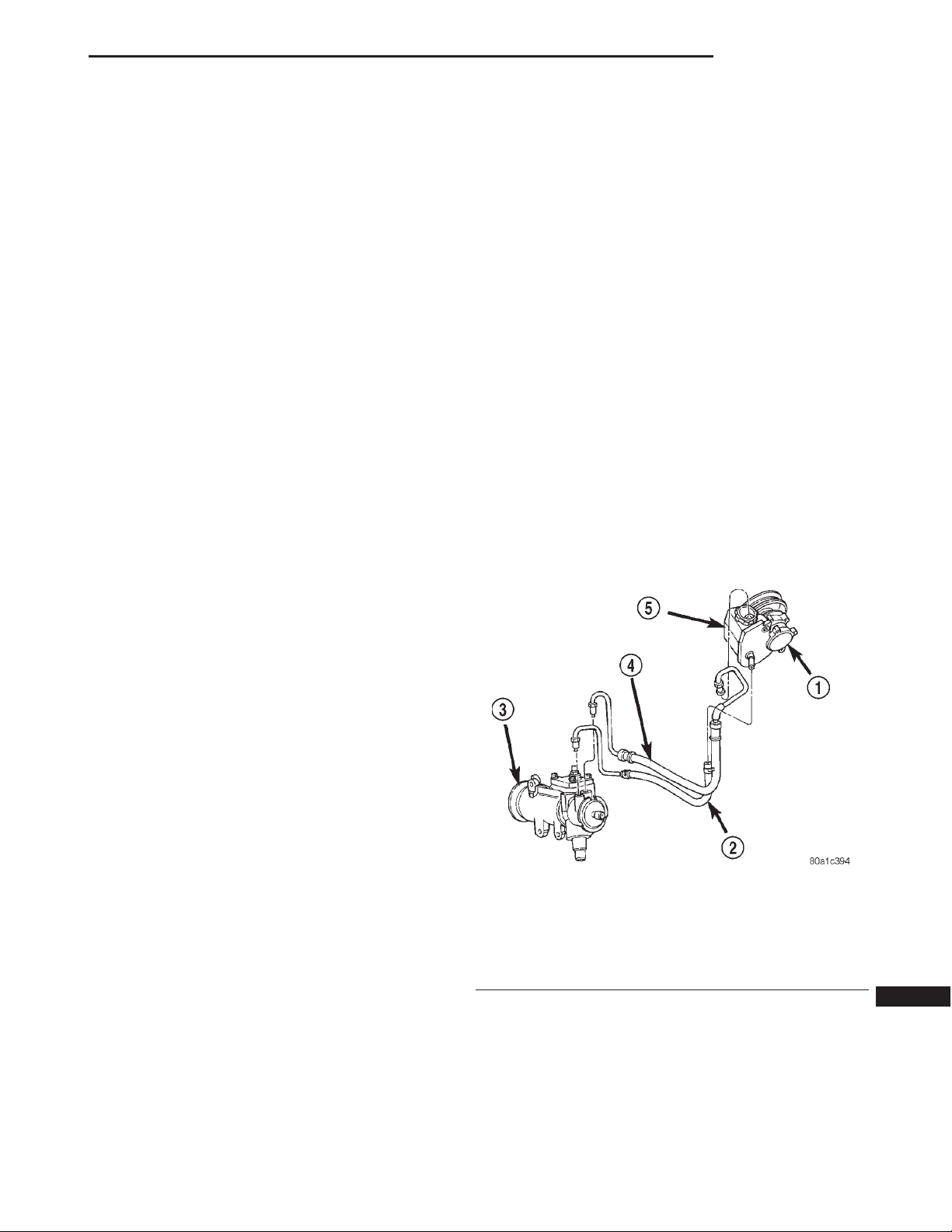
The power steering system has a hydraulic pump.
The pump is a constant flow rate and displacement,
vane-type pump. The pump on the 4.0L engine has a
reservoir mounted to it (Fig. 1). The 2.5L engine has
a remote mounted reservoir.
The steering gear (Fig. 1) used is a recirculating
ball type gear with 14:1 gear ratio. A tilt and non-tilt
column provide steering input.
STEERING LINKAGE ....................... 22
STEERING COLUMN....................... 26
DIAGNOSIS AND TESTING
POWER STEERING SYSTEM DIAGNOSIS
CHARTS...............................2
NOTE: Right hand drive (RHD) and left hand drive
(LHD) service procedures and torque specifications
for steering linkage, gear and column are the same.
The power steering pump procedures are different.
Refer to appropriate service procedures regarding
each component in the system.
OPERATION
The steering gear acts as a rolling thread between
the worm shaft and the rack piston. Power assist is
provided by the hydraulic pump. When the steering
wheel is turned the worm shaft turns which moves
Fig. 1 Power Steering Gear & Pump - 4.0L
1 – 4.0 L PUMP
2 – RETURN HOSE
3 – STEERING GEAR
4 – PRESSURE HOSE
5 – RESERVOIR
the rack piston. The rack piston movement turns the
pitman shaft which is connected to the steering linkage by the pitman arm.
Page 2
19 - 2 STEERING XJ
DIAGNOSIS AND TESTING
POWER STEERING SYSTEM DIAGNOSIS CHARTS
STEERING NOISE
There is some noise in all power steering systems. One of the most common is a hissing sound evident at a
standstill parking. Or when the steering wheel is at the end of it’s travel. Hiss is a high frequency noise similar
to that of a water tap being closed slowly. The noise is present in all valves that have a high velocity fluid passing
through an orifice. There is no relationship between this noise and steering performance.
CONDITION POSSIBLE CAUSES CORRECTION
OBJECTIONAL HISS OR
WHISTLE
RATTLE OR CLUNK 1. Gear mounting bolts loose. 1. Tighten bolts to specification.
CHIRP OR SQUEAL 1. Loose belt. 1. Adjust or replace.
WHINE OR GROWL 1. Low fluid level. 1. Fill to proper level.
SUCKING AIR SOUND 1. Loose return line clamp. 1. Replace clamp.
1. Steering intermediate shaft to dash panel
seal.
2. Noisy valve in power steering gear. 2. Replace steering gear.
2. Loose or damaged suspension
components/track bar.
3. Loose or damaged steering linkage. 3. Inspect and repair steering
4. Internal gear noise. 4. Replace gear.
5. Pressure hose in contact with other
components.
2. Pressure hose in contact with other
components.
3. Internal pump noise. 3. Replace pump.
4. Air in the system. 4. Perform pump initial operation.
2. O-ring missing or damaged on hose
fitting.
3. Low fluid level. 3. Fill to proper level.
4. Air leak between pump and reservoir. 4. Repair as necessary.
1. Check and repair seal at dash
panel.
2. Inspect and repair suspension.
linkage.
5. Reposition hose.
2. Reposition hose.
2. Replace o-ring.
SCRUBBING OR
KNOCKING
1. Wrong tire size. 1. Verify tire size.
2. Wrong gear. 2. Verify gear.
Page 3
XJ STEERING 19 - 3
DIAGNOSIS AND TESTING (Continued)
BINDING AND STICKING
CONDITION POSSIBLE CAUSE CORRECTION
DIFFICULT TO TURN WHEEL
STICKS OR BINDS
INSUFFICIENT ASSIST OR POOR RETURN TO CENTER
CONDITION POSSIBLE CAUSE CORRECTION
HARD TURNING OR MOMENTARY
INCREASE IN TURNING EFFORT
1. Low fluid level. 1. Fill to proper level.
2. Tire pressure. 2. Adjust tire pressure.
3. Steering component. 3. Inspect and lube.
4. Loose belt. 4. Adjust or replace.
5. Low pump pressure. 5. Pressure test and replace if
necessary.
6. Column shaft coupler binding. 6. Replace coupler.
7. Steering gear worn or out of
adjustment.
8. Ball joints binding. 8. Inspect and repair as necessary.
1. Tire pressure. 1. Adjust tire pressure.
2. Low fluid level. 2. Fill to proper level.
3. Loose belt. 3. Adjust or replace.
4. Lack of lubrication. 4. Inspect and lubricate steering and
5. Low pump pressure. 5. Pressure test and repair as
6. Internal gear leak. 6. Pressure and flow test, and repair
7. Repair or replace gear.
suspension compnents.
necessary.
as necessary.
STEERING WHEEL
DOES NOT WANT TO RETURN TO
CENTER POSITION
Some roads will cause a vehicle to drift, due to the
crown in the road.
1. Tire pressure. 1. Adjust tire pressure.
2. Wheel alignment. 2. Align front end.
3. Lack of lubrication. 3. Inspect and lubricate steering and
4. High friction in steering gear. 4. Test and adjust as necessary.
5. Ball joints binding. 5. Inspect and repair as necessary.
suspension compnents.
Page 4
19 - 4 STEERING XJ
DIAGNOSIS AND TESTING (Continued)
LOOSE STEERING AND VEHICLE LEADS/DRIFTS
CONDITION POSSIBLE CAUSE CORRECTION
EXCESSIVE PLAY IN STEERING
WHEEL
VEHICLE PULLS TO ONE SIDE
DURING BRAKING
VEHICLE LEADS OR DRIFTS
FROM STRAIGHT AHEAD
DIRECTION ON UNCROWNED
ROAD.
1. Worn or loose suspension or
steering components.
2. Worn or loose wheel bearings. 2. Repair as necessary.
3. Steering gear mounting. 3. Tighten gear mounting bolts to
4. Gear out of adjustment. 4. Adjust gear to specification.
5. Worn or loose steering coupler. 5. Repair as necessary.
1. Tire Pressure. 1. Adjust tire pressure.
2. Air in brake hydrauliics system. 2. Bleed brake system.
3. Worn brake components. 3. Repair as necessary.
1. Tire pressure. 1. Adjust tire pressure.
2. Radial tire lead. 2. Cross front tires.
3. Brakes dragging. 3. Repair as necessary.
4. Wheel alignment. 4. Align vehicle.
5. Weak or broken spring. 5. Replace spring.
6. Loose or worn steering/
suspension components.
7. Cross caster out of spec. 7. Adjust or replace axle as
1. Repair as necessary.
specification.
6. Repair as necessary.
necessary.
Page 5
XJ STEERING 19 - 5
POWER STEERING PUMP
TABLE OF CONTENTS
page page
DESCRIPTION AND OPERATION
POWER STEERING PUMP ..................5
POWER STEERING PRESSURE LINE ..........5
POWER STEERING RETURN LINE ............6
DIAGNOSIS AND TESTING
POWER FLOW AND PRESSURE..............6
PUMP LEAKAGE DIAGNOSIS ................7
SERVICE PROCEDURES
POWER STEERING PUMP - INITIAL
OPERATION ............................7
DESCRIPTION AND OPERATION
POWER STEERING PUMP
DESCRIPTION
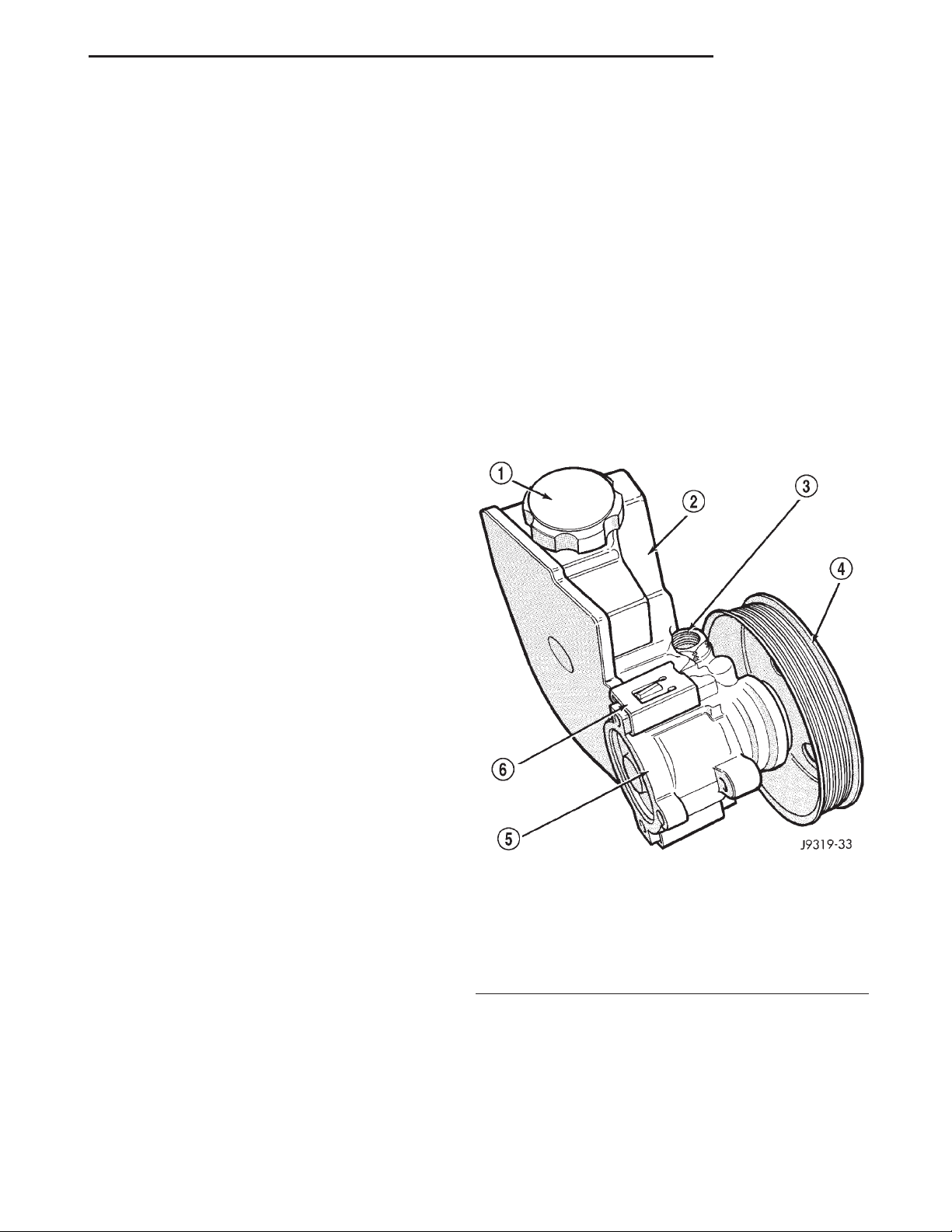
Hydraulic pressure for the power steering system
is provided by a belt driven power steering pump
(Fig. 1). The pump shaft has a pressed-on high
strength plastic drive pulley that is belt driven by
the crankshaft pulley. The reservoir is attached to
the pump body with spring clips on the 4.0L engine.
A remote pump reservoir is used on the 2.5L engine
mounted to the fan shroud. The power steering pump
is connected to the steering gear by the pressure and
return hoses.
REMOVAL AND INSTALLATION
POWER STEERING PUMP ..................7
PUMP RESERVOIR-2.5L ....................7
DISASSEMBLY AND ASSEMBLY
PUMP PULLEY ...........................8
PUMP RESERVOIR ........................8
SPECIFICATIONS
TORQUE CHART .........................10
SPECIAL TOOLS
POWER STEERING PUMP .................10
OPERATION
The power steering pump is a constant flow rate
and displacement, vane-type pump. The pump internal parts operate submerged in fluid. The flow control orifice is part of the high pressure line fitting.
The pressure relief valve inside the flow control valve
limits the pump pressure.
NOTE: Power steering pumps have different pressure rates and are not interchangeable with other
pumps.
POWER STEERING PRESSURE LINE
DESCRIPTION
The hose consists of two metal ends and rubber
center section that contains a tuning cable.
Fig. 1 Pump With Integral Reservoir
1 – CAP
2 – FLUID RESERVOIR (TYPICAL)
3 – HIGH-PRESSURE FITTING
4 – DRIVE PULLEY
5 – PUMP BODY
6 – RESERVOIR CLIP
OPERATION
Power steering pressure line, is used to transfer
high pressure power steering fluid, from the power
steering pump to the power steering gear.
Page 6
19 - 6 STEERING XJ
DESCRIPTION AND OPERATION (Continued)
POWER STEERING RETURN LINE
DESCRIPTION
Power steering return line is a hose which is
clamped at the pump and the gear.
OPERATION
Power steering return line, is used to transfer low
pressure power steering fluid, from the power steering gear to the power steering pump.
DIAGNOSIS AND TESTING
POWER FLOW AND PRESSURE
The following procedure is used to test the operation of the power steering system on the vehicle. This
test will provide the gallons per minute (GPM) or
flow rate of the power steering pump along with the
maximum relief pressure. Perform test any time a
power steering system problem is present. This test
will determine if the power steering pump or power
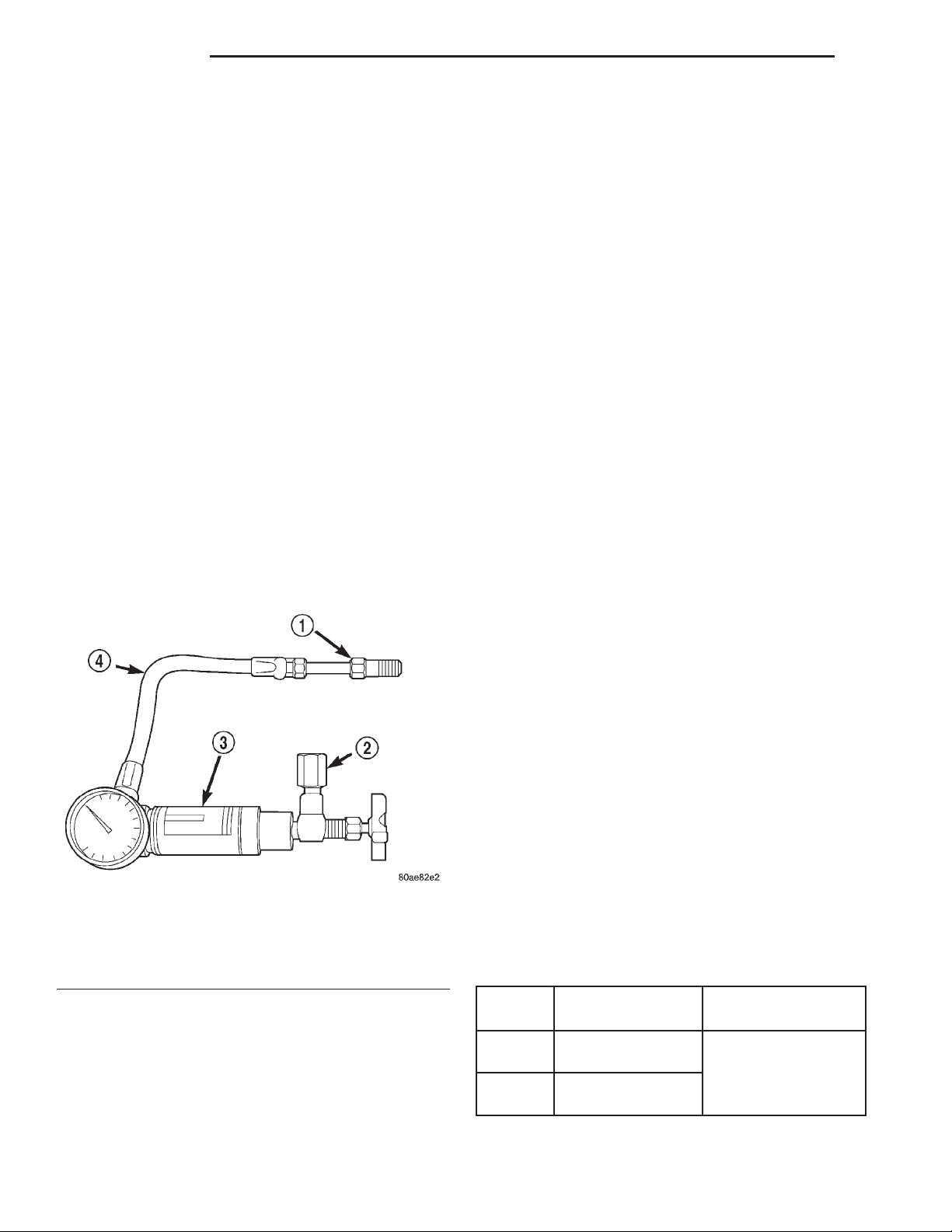
steering gear is not functioning properly. The following pressure and flow test is performed using Power
Steering Analyzer Tool Kit 6815 (Fig. 2) and Adapter
Kit 6893.
(4) Disconnect high pressure hose at the pump.
Use a container for dripping fluid.
(5) Connect Tube 6865 to the pump hose fitting.
(6) Connect the power steering hose from the
steering gear to Adapter 6826.
(7) Open the test valve completely.
(8) Start engine and let idle long enough to circulate power steering fluid through flow/pressure test
gauge and to get air out of the fluid. Then shut off
engine.
(9) Check fluid level, add fluid as necessary. Start
engine again and let idle.
(10) Gauge should read below 862 kPa (125 psi), if
above, inspect the hoses for restrictions and repair as
necessary. The initial pressure reading should be in
the range of 345-552 kPa (50-80 psi).
(11) Increase the engine speed to 1500 RPM and
read the flow meter. The reading should be 2.4 - 2.8
GPM, if the reading is below this specification the
pump should be replaced.
CAUTION: The next step involves testing maximum
pump pressure output and flow control valve operation. Do not leave valve closed for more than three
seconds as the pump could be damaged.
(12) Close valve fully three times and record highest pressure indicated each time. All three read-
ings must be above specifications and within
345 kPa (50 psi) of each other.
• Pressures above specifications but not within
345 kPa (50 psi) of each other, replace pump.
• Pressures within 345 kPa (50 psi) of each other
but below specifications, replace pump.
(13) Open the test valve, turn steering wheel
extreme left and right positions against the stops.
Record the highest indicated pressure at each position. Compare readings to specifications. If highest
output pressures are not the same against either
stop, the gear is leaking internally and must be
repaired.
Fig. 2 Power Steering Analyzer
1 – TUBE
2 – ADAPTER FITTINGS
3 – ANALYZER
4 – GAUGE HOSE
FLOW AND PRESSURE TEST
(1) Check the power steering belt to ensure it is in
good condition and adjusted properly.
(2) Connect pressure gauge hose from the Power
Steering Analyzer to Tube 6865.
(3) Connect Adapter 6826 to Power Steering Ana-
lyzer test valve end.
CAUTION: Do not force the pump to operate
against the stops for more than 2 to 3 seconds at a
time because, pump damage will result.
PUMP SPECIFICATIONS
ENGINE
2.5L
4.0L
RELIEF
PRESSURE 6 50
9653 kPa
(1400 psi)
9653 kPa
(1400 psi)
FLOW RATE (GPM)
1500 RPM 2.4 - 2.8
GPM
Page 7
XJ STEERING 19 - 7
DIAGNOSIS AND TESTING (Continued)
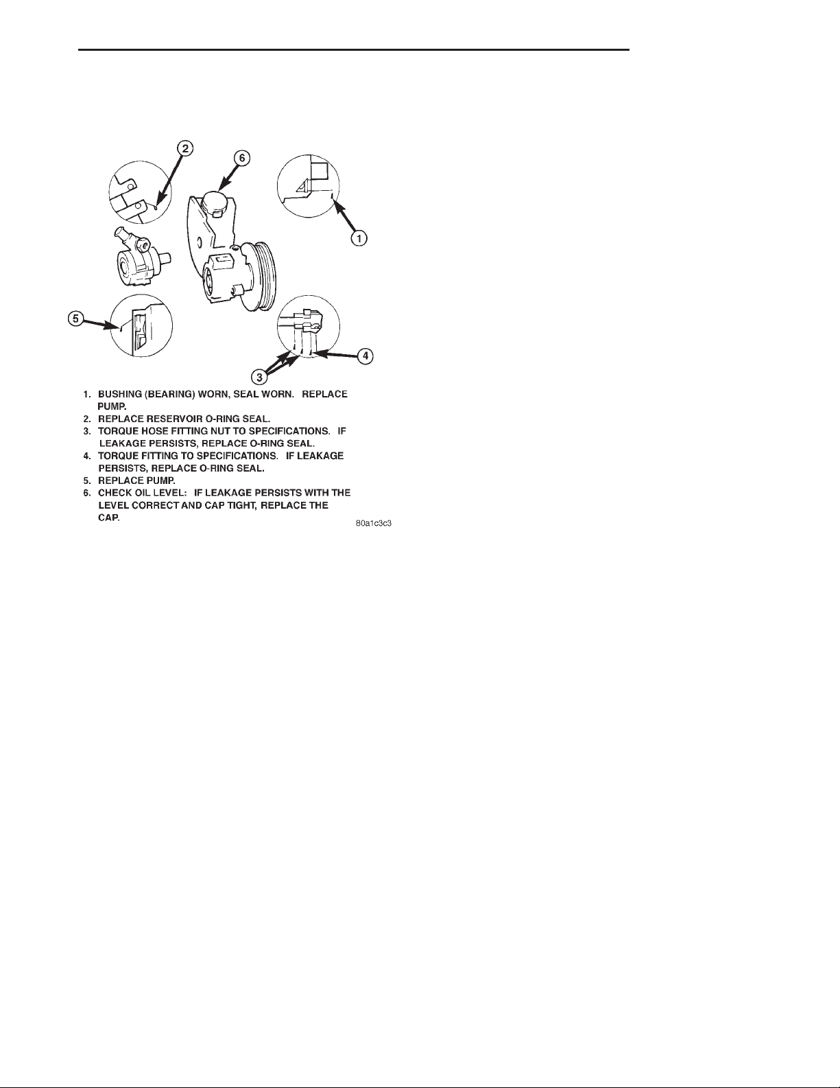
PUMP LEAKAGE DIAGNOSIS
SERVICE PROCEDURES
POWER STEERING PUMP - INITIAL OPERATION
WARNING: THE FLUID LEVEL SHOULD BE
CHECKED WITH ENGINE OFF TO PREVENT INJURY
FROM MOVING COMPONENTS.
CAUTION: Use MOPAR Power Steering Fluid or
equivalent. Do not use automatic transmission fluid
and do not overfill.
Wipe filler cap clean, then check the fluid level.
The dipstick should indicate COLD when the fluid is
at normal ambient temperature.
(1) Fill the pump fluid reservoir to the proper level
and let the fluid settle for at least two minutes.
(2) Start the engine and let run for a few seconds
then turn engine off.
(3) Add fluid if necessary. Repeat the above procedure until the fluid level remains constant after running the engine.
(4) Raise the front wheels off the ground.
(5) Slowly turn the steering wheel right and left,
lightly contacting the wheel stops at least 20 times.
(6) Check the fluid level add if necessary.
(7) Lower the vehicle, start the engine and turn
the steering wheel slowly from lock to lock.
(8) Stop the engine and check the fluid level and
refill as required.
(9) If the fluid is extremely foamy or milky looking, allow the vehicle to stand a few minutes and
repeat the procedure.
CAUTION: Do not run a vehicle with foamy fluid for
an extended period. This may cause pump damage.
REMOVAL AND INSTALLATION
POWER STEERING PUMP
NOTE: The power steering pump is mounted in the
same position on LHD and RHD vehicles. On 4.0L
RHD vehicles the front bracket is different. The service procedures are the same.
REMOVAL
(1) Remove serpentine drive belt, refer to Group 7
Cooling.
(2) Remove pressure and return hoses from pump,
and drain pump.
(3) Remove 3 pump mounting bolts through pulley
access holes.
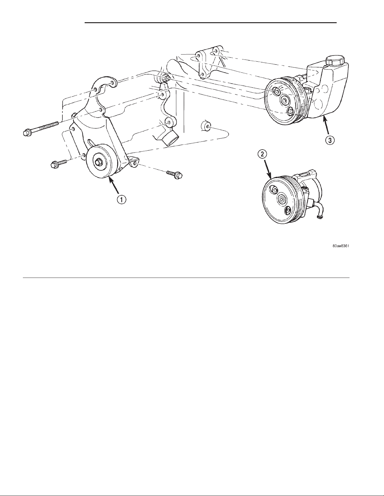
(4) Loosen the 3 pump bracket bolts (Fig. 3) and
(Fig. 4).
(5) Tilt pump downward and remove from engine.
(6) Remove pulley from pump.
INSTALLATION
(1) Install pulley on pump.
(2) Install pump on engine.
(3) Tighten pump bracket bolts to 47 N·m (35 ft.
lbs.).
(4) Install 3 pump mounting bolts and tighten to
27 N·m (20 ft. lbs.).
(5) Install the pressure and return hoses to pump.
(6) Install drive belt, refer to Group 7 Cooling.
(7) Add power steering fluid and perform Power
Steering Pump Initial Operation.
PUMP RESERVOIR-2.5L
REMOVAL
(1) Remove the hoses from the bottom of the reservoir and drain the reservoir.
(2) Remove the push-in fastener from the top of
the fan shroud.
(3) Slide reservoir up off the fan shroud.
INSTALLATION
(1) Slide reservoir down onto fan shroud.
(2) Install the push-in fastener in the top of fan
shroud.
Page 8
19 - 8 STEERING XJ
REMOVAL AND INSTALLATION (Continued)
Fig. 3 Pump Mounting LHD
1 – PUMP BRACKET
2 – PUMP ASSEMBLY 2.5L
(3) Install the pump hoses.
(4) Fill reservoir to proper level. Refer to Power
Steering Pump Initial Operation.
DISASSEMBLY AND ASSEMBLY
PUMP PULLEY
DISASSEMBLY
(1) Remove pump assembly.
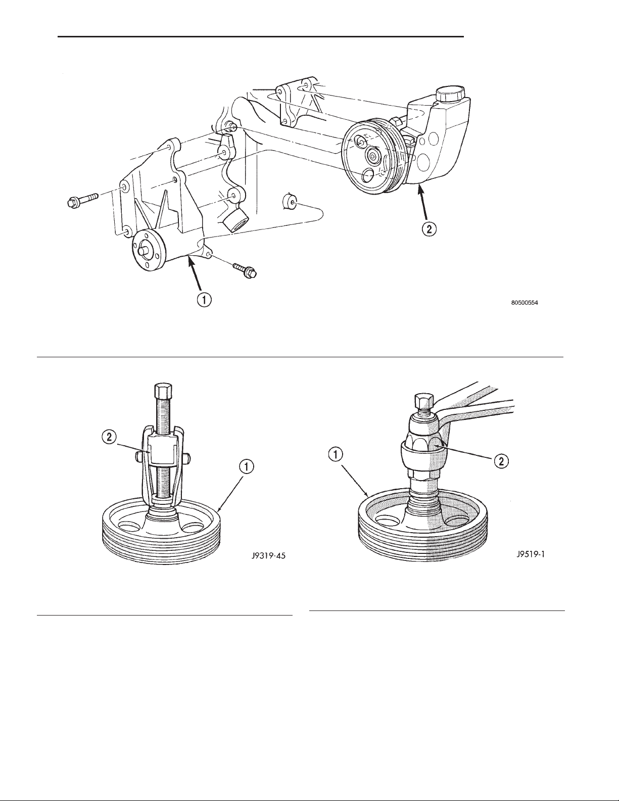
(2) Remove pulley from pump with Puller C-4333
or equivalent puller (Fig. 5).
ASSEMBLY
NOTE: The pulley is marked front for installation.
(1) Replace pulley if bent, cracked, or loose.
(2) Install pulley on pump with Installer C-4063-B
or equivalent installer (Fig. 6). The pulley must be
flush with the end of the shaft. Ensure the tool and
pulley are aligned with the pump shaft.
(3) Install pump assembly.
3 – PUMP ASSEMBLY 4.0L
(4) With Serpentine Belt, run engine until warm (5
min.) and note any belt chirp. If chirp exists, move
pulley outward approximately 0.5 mm (0.020 in.). If
noise increases, press on 1.0 mm (0.040 in.). Be
careful that pulley does not contact mounting
bolts.
PUMP RESERVOIR
DISASSEMBLY
(1) Remove power steering pump.
(2) Clean exterior of pump.
(3) Clamp the pump body in a soft jaw vice.
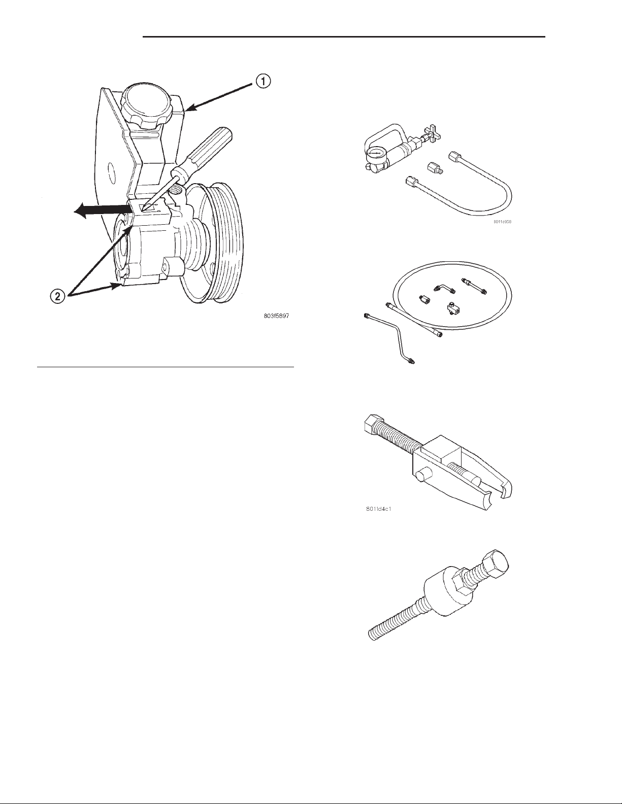
(4) Pry up tab and slide the retaining clips off (Fig.
7).
NOTE: Use new retaining clips for installation.
(5) Remove fluid reservoir from pump body.
Remove and discard O-ring seal.
ASSEMBLY
(1) Lubricate new O-ring Seal with Mopar Power
Steering Fluid or equivalent.
Page 9
XJ STEERING 19 - 9
DISASSEMBLY AND ASSEMBLY (Continued)
Fig. 4 Pump Mounting 4.0L RHD
1 – BRACKET
2 – PUMP ASSEMBLY
Fig. 5 Pulley Removal
1 – POWER STEERING PUMP DRIVE PULLEY
2 – SPECIAL TOOL C-4333
(2) Install O-ring seal in housing.
(3) Install reservoir onto housing.
(4) Slide and tap in new reservoir retainer clips
until tab locks to housing.
Fig. 6 Pulley Installation
1 – POWER STEERING PUMP DRIVE PULLEY
2 – SPECIAL TOOL C-4063–B
(5) Install power steering pump.
(6) Add power steering fluid, refer to Pump Initial
Operation.
Page 10
19 - 10 STEERING XJ
DISASSEMBLY AND ASSEMBLY (Continued)
SPECIAL TOOLS
POWER STEERING PUMP
Analyzer Set, Power Steering Flow/Pressure 6815
Fig. 7 Pump Reservoir Clips
1 – RESERVOIR
2 – RETAINING CLIPS
SPECIFICATIONS
TORQUE CHART
DESCRIPTION TORQUE
Power Steering Pump
Bracket to Pump .......... 28N·m(21ft.lbs.)
Bracket to Engine ......... 47N·m(35ft.lbs.)
Flow Control Valve ........ 75N·m(55ft.lbs.)
Pressure Line ............. 28N·m(21ft.lbs.)
Adapters, Power Steering Flow/Pressure Tester
6893
Puller C-4333
Installer, Power Steering Pulley C-4063B
Page 11
XJ STEERING 19 - 11
POWER STEERING GEAR
TABLE OF CONTENTS
page page
DESCRIPTION AND OPERATION
POWER STEERING GEAR..................11
DIAGNOSIS AND TESTING
POWER STEERING GEAR LEAKAGE .........11
REMOVAL AND INSTALLATION
STEERING GEAR ........................12
DISASSEMBLY AND ASSEMBLY
HOUSING END PLUG .....................12
PITMAN SHAFT/SEALS/BEARING ............12
DESCRIPTION AND OPERATION
POWER STEERING GEAR
DESCRIPTION
The power steering gear is a recirculating ball type
gear with a 14:1 ratio.
OPERATION
The gear acts as a rolling thread between the
worm shaft and rack piston. The worm shaft is supported by a thrust bearing at the lower end and a
bearing assembly at the upper end. When the worm
shaft is turned the rack piston moves. The rack piston teeth mesh with the pitman shaft. Turning the
worm shaft turns the pitman shaft, which turns the
steering linkage.
SPOOL VALVE...........................14
RACK PISTON AND WORM SHAFT ...........16
ADJUSTMENTS
STEERING GEAR ........................19
SPECIFICATIONS
POWER STEERING GEAR..................21
TORQUE CHART .........................21
SPECIAL TOOLS
POWER STEERING GEAR..................21
DIAGNOSIS AND TESTING
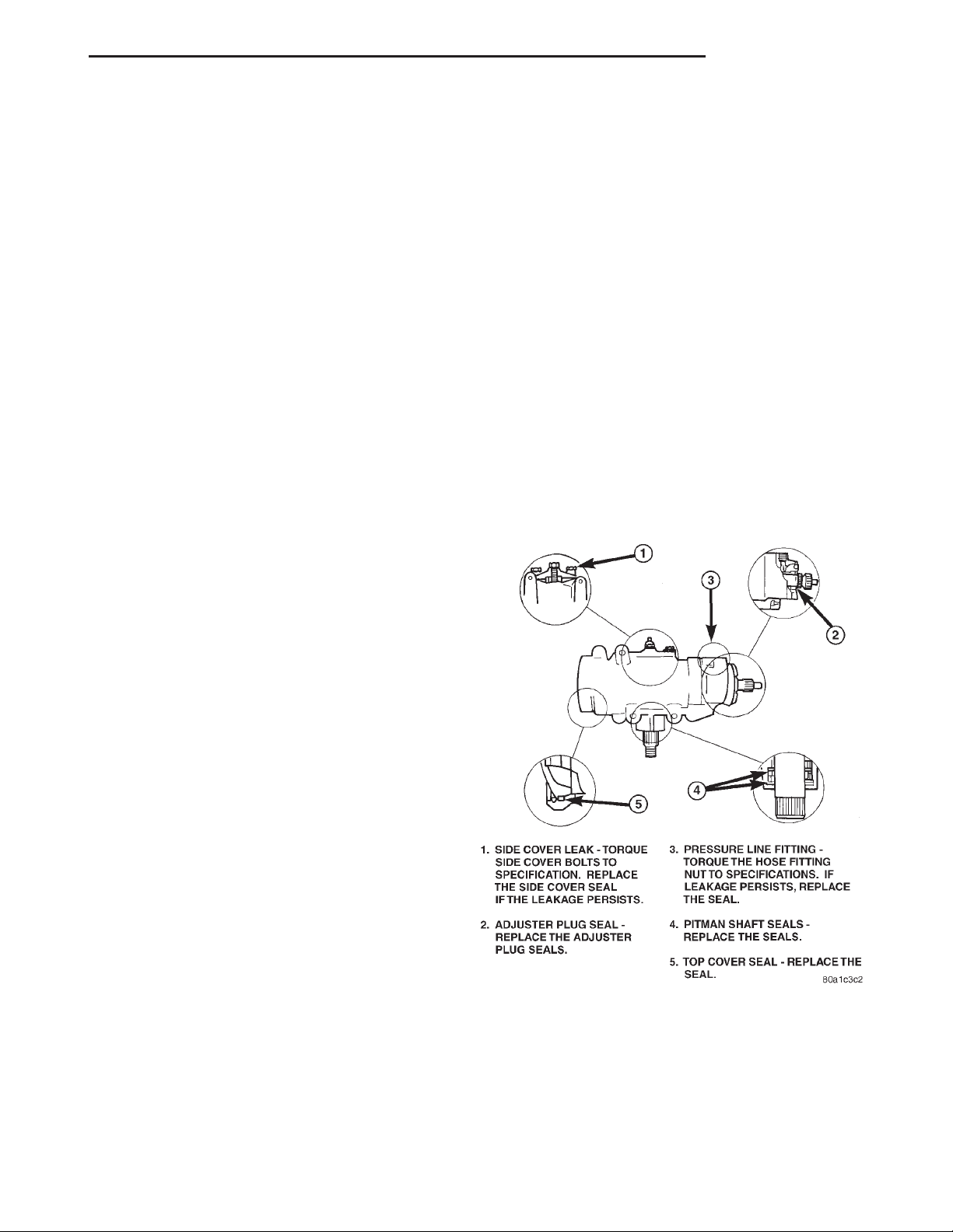
POWER STEERING GEAR LEAKAGE
CAUTION: Components attached with a nut and
cotter pin must be torqued to specification. Then if
the slot in the nut does not line up with the cotter
pin hole, tighten nut until it is aligned. Never loosen
the nut to align the cotter pin hole.
Page 12
19 - 12 STEERING XJ
REMOVAL AND INSTALLATION
STEERING GEAR
REMOVAL
(1) Place the front wheels in the straight ahead
position with the steering wheel centered.
(2) Disconnect and cap the fluid hoses from steering gear.
(3) Remove the column coupler shaft from the
gear.
(4) Remove pitman arm from gear.
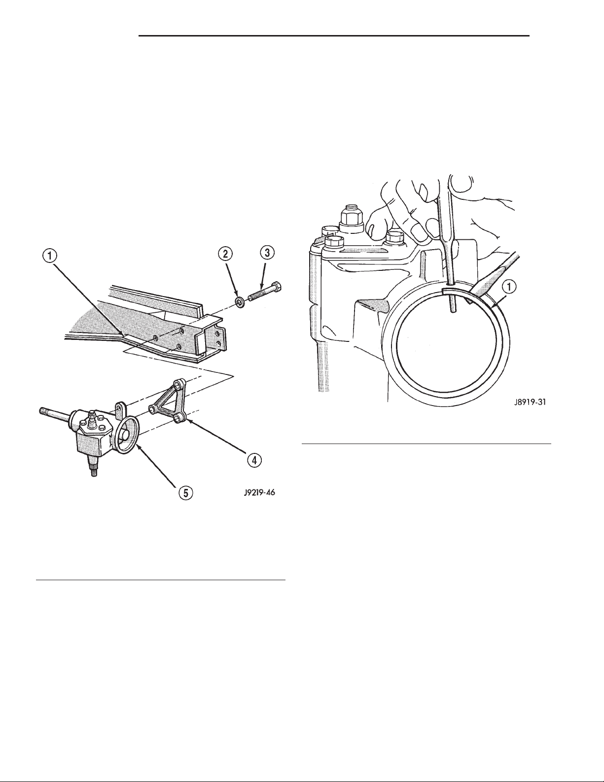
(5) Remove the steering gear retaining bolts and
remove the gear (Fig. 1).
DISASSEMBLY AND ASSEMBLY
HOUSING END PLUG
DISASSEMBLY
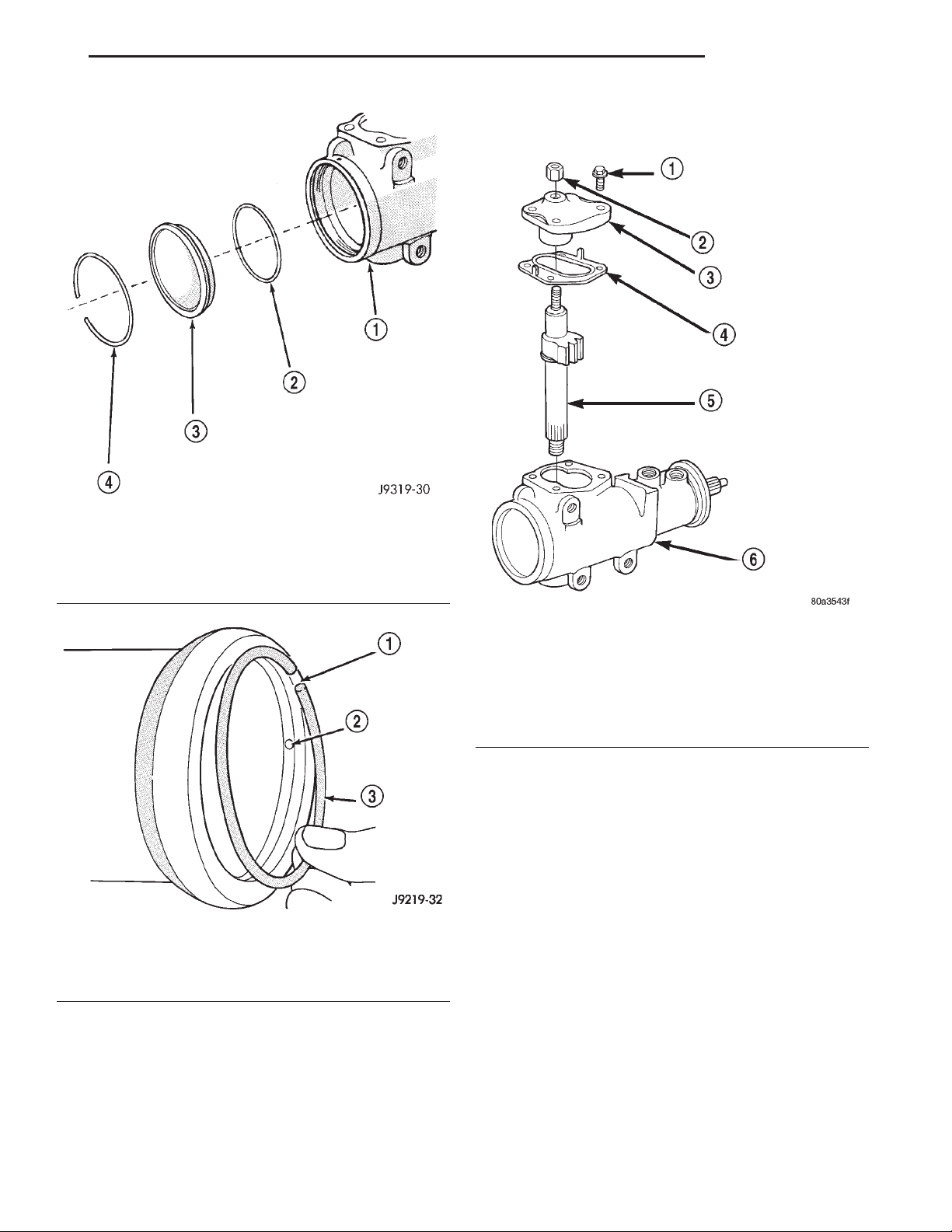
(1) Unseat and remove retaining ring from groove
with a punch through the hole in the end of the
housing (Fig. 2).
Fig. 1 Steering Gear Mounting (LHD)
1 – FRAME
2 – WASHER
3 – SCREW
4 – ADAPTER
5 – GEAR
INSTALLATION
(1) Install steering gear (and bracket) on the frame
rail and tighten bolts to 95 N·m (70 ft. lbs.).
(2) Align the column coupler shaft to steering gear.
Install a new pinch bolt and tighten to 49 N·m (36
ft. lbs.).
(3) Align and install the pitman arm and tighten
nut to 251 N·m (185 ft. lbs.).
(4) Connect fluid hoses to steering gear and
tighten to 28 N·m (21 ft. lbs.).
(5) Fill power steering system to proper level.
Fig. 2 End Plug Retaining Ring
1 – RETAINING RING
(2) Slowly rotate stub shaft with 12 point socket
COUNTER-CLOCKWISE to force the end plug out
from housing.
CAUTION: Do not turn stub shaft any further than
necessary. The rack piston balls will drop out of the
rack piston circuit if the stub shaft is turned too far.
(3) Remove O-ring from the housing (Fig. 3).
ASSEMBLY
(1) Lubricate O-ring with power steering fluid and
install into the housing.
(2) Install end plug by tapping the plug lightly
with a plastic mallet into the housing.
(3) Install retaining ring so one end of the ring
covers the housing access hole (Fig. 4).
PITMAN SHAFT/SEALS/BEARING
DISASSEMBLY
(1) Clean exposed end of pitman shaft and housing
with a wire brush.
(2) Remove preload adjuster nut (Fig. 5).
Page 13
XJ STEERING 19 - 13
DISASSEMBLY AND ASSEMBLY (Continued)
NOTE: The pitman shaft will not clear the housing
if it is not centered.
Fig. 3 End Plug Components
1 – HOUSING ASSEMBLY
2 – HOUSING END PLUG O-RING SEAL
3 – HOUSING END PLUG
4 – RETAINING RING
Fig. 4 Installing The Retaining Ring
1 – RING CAP
2 – PUNCH ACCESS HOLE
3 – RETAINER RING
Fig. 5 Side Cover and Pitman Shaft
1 – SIDE COVER BOLTS
2 – PRELOAD ADJUSTER NUT
3 – SIDE COVER
4 – GASKET SEAL
5 – PITMAN SHAFT GEAR
6 – HOUSING ASSEMBLY
(6) Remove pitman shaft from the side cover.
(7) Remove dust seal from the housing with a seal
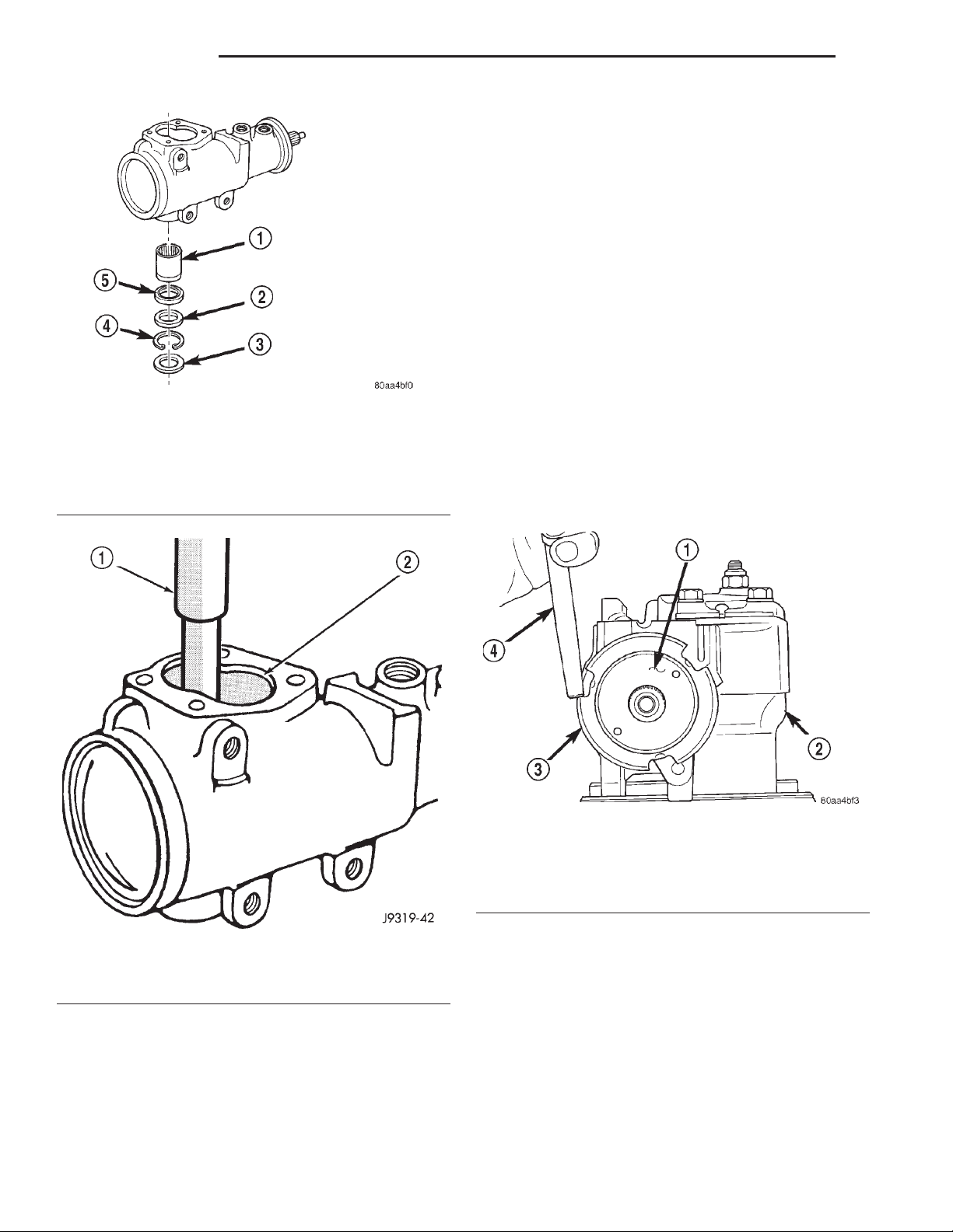
pick (Fig. 6).
CAUTION: Use care not to score the housing bore
when prying out seals and washer.
(8) Remove retaining ring with snap ring pliers.
(9) Remove washer from the housing.
(10) Remove oil seal from the housing with a seal
pick.
(11) Remove pitman shaft bearing from housing
with a bearing driver and handle (Fig. 7).
(3) Rotate the stub shaft with a 12 point socket
from stop to stop and count the number of turns.
(4) Center the stub shaft by rotating it from the
stop 1/2 of the total amount of turns.
(5) Remove side cover bolts and remove side cover,
gasket and pitman shaft as an assembly (Fig. 5).
ASSEMBLY
(1) Install pitman shaft bearing into housing with
a bearing driver and handle.
(2) Coat the oil seal and washer with special
grease supplied with the new seal.
(3) Install the oil seal with a driver and handle.
(4) Install backup washer.
Page 14
19 - 14 STEERING XJ
DISASSEMBLY AND ASSEMBLY (Continued)
(9) Install preload adjuster nut. Do not tighten
nut until after Over-Center Rotation Torque
adjustment has been made.
(10) Install gasket to side cover and bend tabs
around edges of side cover (Fig. 5).
(11) Install pitman shaft assembly and side cover
to housing.
(12) Install side cover bolts and tighten to 60 N·m
(44 ft. lbs.).
(13) Perform over-center rotation torque adjustment.
SPOOL VALVE
DISASSEMBLY
Fig. 6 Pitman Shaft Seals & Bearing
1 – BEARING
2 – WASHER
3 – DUST SEAL
4 – RETAINER
5 – OIL SEAL
(1) Remove lock nut (Fig. 8).
(2) Remove adjuster nut with Spanner Wrench
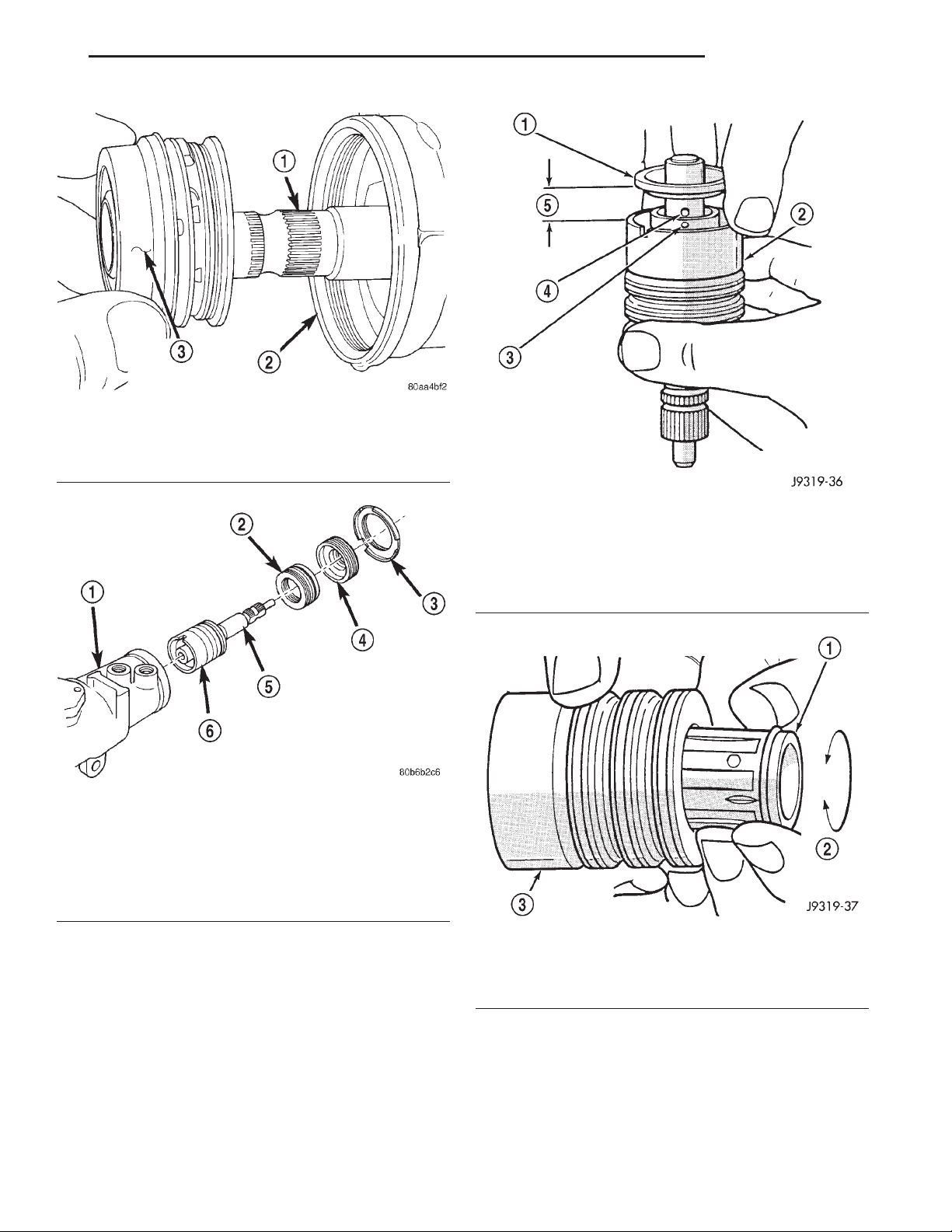
C-4381.
(3) Remove thrust support assembly out of the
housing (Fig. 9).
(4) Pull stub shaft and valve assembly from the
housing (Fig. 10).
Fig. 7 Needle Bearing Removal
1 – REMOVER
2 – SIDE COVER AREA
(5) Install the retainer ring with snap ring pliers.
(6) Coat the dust seal with special grease sup-
plied with the new seal.
(7) Install dust seal with a driver and handle.
(8) Install pitman shaft to side cover by screwing
shaft in until it fully seats to side cover.
Fig. 8 Lock Nut and Adjuster Nut
1 – ADJUSTER NUT
2 – STEERING GEAR
3 – LOCK NUT
4 – PUNCH
(5) Remove stub shaft from valve assembly by
lightly tapping shaft on a block of wood to loosen
shaft. Then disengage stub shaft pin from hole in
spool valve and separate the valve assembly from
stub shaft (Fig. 11).
(6) Remove spool valve from valve body by pulling
and rotating the spool valve from the valve body (Fig.
12).
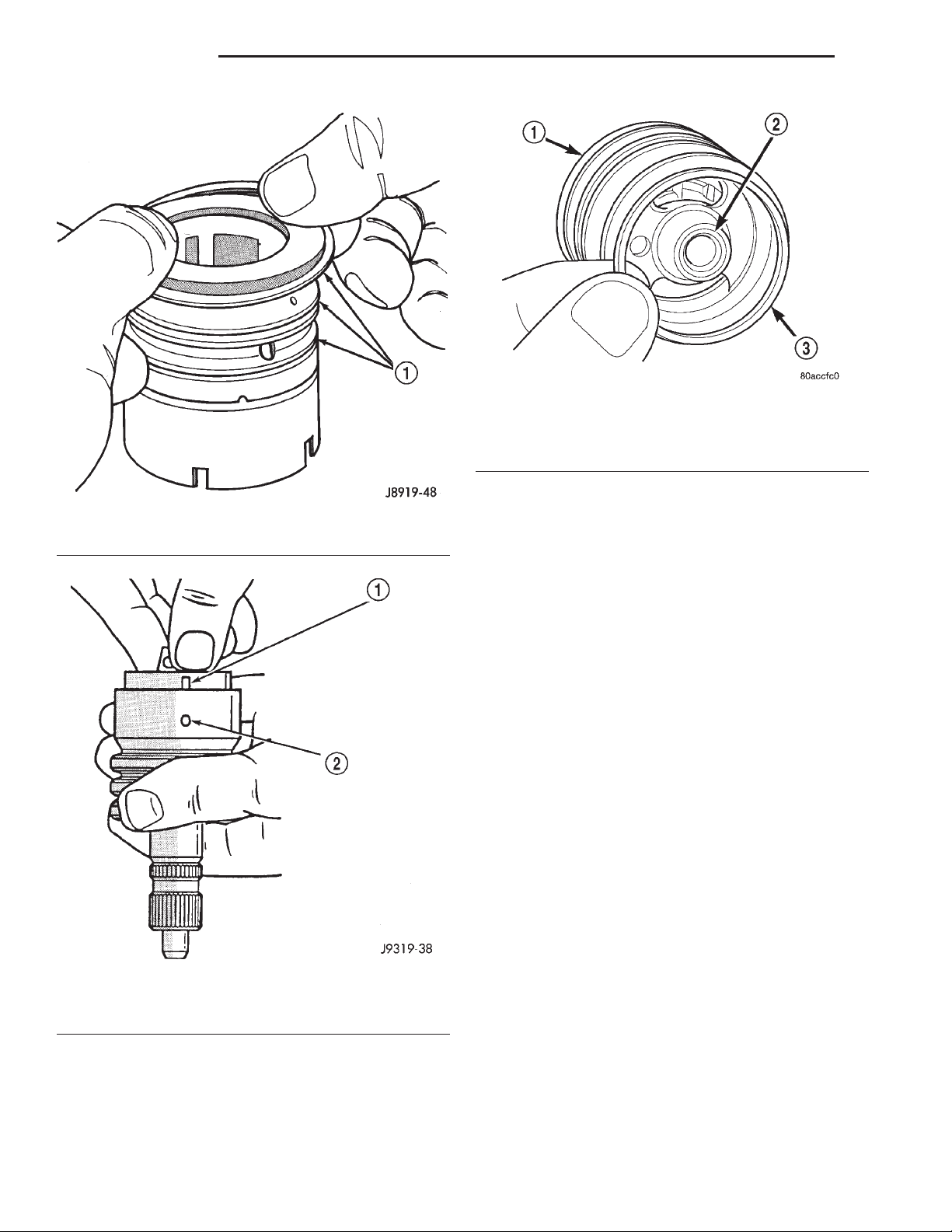
(7) Remove spool valve O-ring and valve body
teflon rings and O-rings underneath the teflon rings
(Fig. 13).
Page 15
XJ STEERING 19 - 15
DISASSEMBLY AND ASSEMBLY (Continued)
Fig. 9 Thrust Support Assembly
1 – STUB SHAFT
2 – HOUSING
3 – THRUST SUPPORT ASSEMBLY
Fig. 10 Valve Assembly With Stub Shaft
1 – GEAR
2 – THRUST SUPPORT
3 – LOCK NUT
4 – ADJUSTER NUT
5 – STUB SHAFT
6 – VALVE ASSEMBLY
(8) Remove the O-ring between the worm shaft
and the stub shaft.
ASSEMBLY
Fig. 11 Stub Shaft
1 – STUB SHAFT
2 – VALVE BODY
3 – HOLE IN SPOOL
4 – SHAFT PIN
5 – 6mm (1/4”)
Fig. 12 Spool Valve
1 – SPOOL VALVE
2 – ROTATE VALVE TO REMOVE
3 – VALVE BODY
NOTE: Clean and dry all components, then lubricate with power steering fluid.
(1) Install spool valve spool O-ring.
(2) Install spool valve in valve body by pushing
and rotating. Hole in spool valve for stub shaft pin
must be accessible from opposite end of valve body.
(3) Install stub shaft in valve spool and engage
locating pin on stub shaft into spool valve hole (Fig.
14).
NOTE: Notch in stub shaft cap must fully engage
valve body pin and seat against valve body shoulder.
Page 16
19 - 16 STEERING XJ
DISASSEMBLY AND ASSEMBLY (Continued)
Fig. 15 Stub Shaft Cap O-Ring
1 – VALVE BODY
2 – STUB SHAFT CAP
3 – O-RING
(6) Install stub shaft and valve assembly in the
Fig. 13 Valve Seals
1 – O-RING SEALS
housing. Line up worm shaft to slots in the valve
assembly.
(7) Install thrust support assembly.
Fig. 14 Stub Shaft Installation
1 – NOTCH IN CAP
2 – VALVE BODY PIN
(4) Install O-rings and teflon rings over the
O-rings on valve body.
(5) Install O-ring into the back of the stub shaft
cap (Fig. 15).
NOTE: The thrust support is serviced as an assembly. If any component of the thrust support is damaged the assembly must be replaced.
(8) Install adjuster nut and lock nut.
(9) Adjust Thrust Bearing Preload and Over-Cen-
ter Rotating Torque.
RACK PISTON AND WORM SHAFT
DISASSEMBLY
(1) Remove housing end plug.
(2) Remove rack piston plug (Fig. 16).
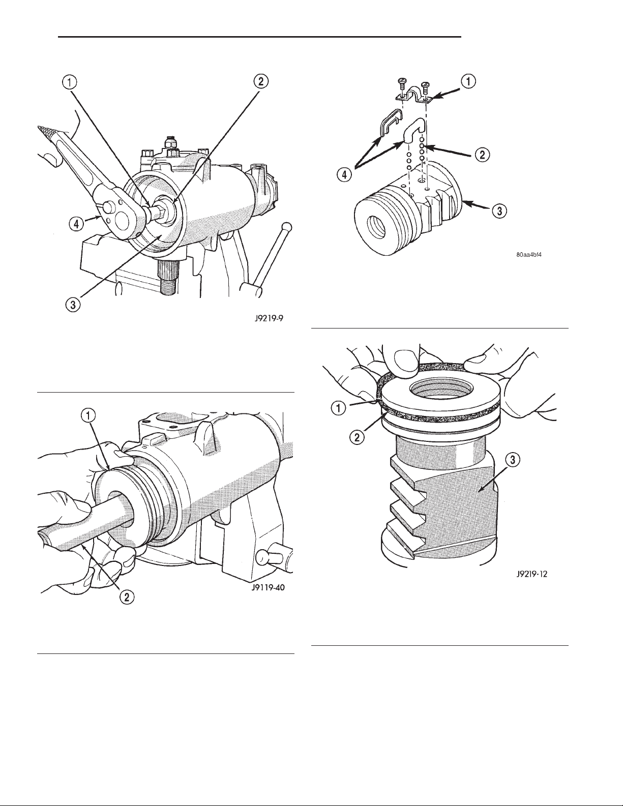
(3) Remove side cover and pitman shaft.
(4) Turn stub shaft COUNTERCLOCKWISE until
the rack piston begins to come out of the housing.
(5) Insert Arbor C-4175 into bore of rack piston
(Fig. 17) and hold tool tightly against worm shaft.
(6) Turn the stub shaft with a 12 point socket
COUNTERCLOCKWISE, this will force the rack piston onto the tool and hold the rack piston balls in
place.
(7) Remove the rack piston and tool together from
housing.
(8) Remove tool from rack piston.
(9) Remove rack piston balls.
(10) Remove clamp bolts, clamp and ball guide
(Fig. 18).
(11) Remove teflon ring and O-ring from the rack
piston (Fig. 19).
Page 17
XJ STEERING 19 - 17
DISASSEMBLY AND ASSEMBLY (Continued)
Fig. 18 Rack Piston
1 – CLAMP
2 – BALLS
3 – RACK PISTON
4 – BALL GUIDE
Fig. 16 Rack Piston End Plug
1 – EXTENSION
2 – END PLUG
3 – RACK PISTON
4 – RATCHET
Fig. 17 Rack Piston with Arbor
1 – RACK PISTON
2 – SPECIAL TOOL C-4175
Fig. 19 Rack Piston Teflon Ring and O-Ring
1 – TEFLON SEAL
2 – BACK-UP O-RING MUST BE INSTALLED UNDER PISTON
RING
3 – RACK PISTON NUT
(12) Remove the adjuster lock nut and adjuster
nut from the stub shaft.
(13) Pull the stub shaft with the spool valve and
thrust support assembly out of the housing.
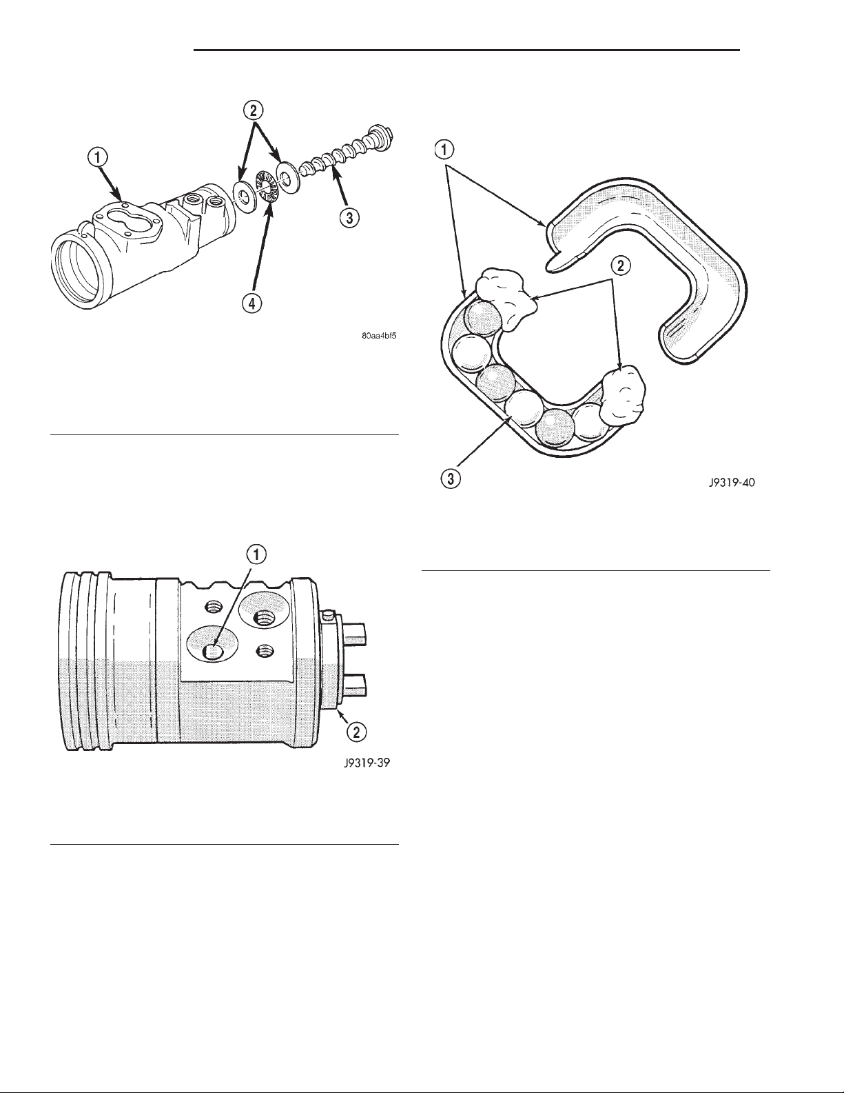
(14) Remove the worm shaft from the housing
(Fig. 20).
ASSEMBLY
NOTE: Clean and dry all components and lubricate
with power steering fluid.
(1) Check for scores, nicks or burrs on the rack
piston finished surface. Slight wear is normal on the
worm gear surfaces.
Page 18
19 - 18 STEERING XJ
DISASSEMBLY AND ASSEMBLY (Continued)
(5) Install remaining balls in guide using grease to
hold the balls in place (Fig. 22).
Fig. 20 Worm Shaft
1 – GEAR HOUSING
2 – BEARING RACE
3 – WORM SHAFT
4 – BEARING
(2) Install O-ring and teflon ring on the rack pis-
ton.
(3) Install worm shaft in the rack piston and align
worm shaft spiral groove with rack piston ball guide
hole (Fig. 21).
Fig. 21 Installing Balls in Rack Piston
1 – INSTALL BALLS IN THIS HOLE WHILE SLOWLY ROTATING
WORM COUNTER CLOCKWISE
2 – WORM FLANGE
CAUTION: The rack piston balls must be installed
alternately into the rack piston and ball guide. This
maintains worm shaft preload. There are 12 black
balls and 12 silver (Chrome) balls. The black balls
are smaller than the silver balls.
(4) Lubricate and install rack piston balls through
return guide hole while turning worm shaft COUNTERCLOCKWISE (Fig. 21).
Fig. 22 Balls in the Return Guide
1 – GUIDE
2 – PETROLEUM JELLY
3 – BALLS
(6) Install the guide onto rack piston and install
clamp and clamp bolts. Tighten bolts to 4.8 N·m (43
in. lbs.).
(7) Insert Arbor C-4175 into bore of rack piston
and hold tool tightly against worm shaft.
(8) Turn the worm shaft COUNTERCLOCKWISE
while pushing on the arbor. This will force the rack
piston onto the arbor and hold the rack piston balls
in place.
(9) Install the races and thrust bearing on the
worm shaft and install shaft in the housing (Fig. 20).
(10) Install the stub shaft with spool valve, thrust
support assembly and adjuster nut in the housing.
(11) Install the rack piston and arbor tool into the
housing.
(12) Hold arbor tightly against worm shaft and
turn stub shaft CLOCKWISE until rack piston is
seated on worm shaft.
(13) Install pitman shaft and side cover in the
housing.
(14) Install rack piston plug and tighten to 150
N·m (111 ft. lbs.).
(15) Install housing end plug.
(16) Adjust worm shaft thrust bearing preload and
over-center rotating torque.
Page 19
XJ STEERING 19 - 19
ADJUSTMENTS
STEERING GEAR
CAUTION: Steering gear must be adjusted in the
proper order. If adjustments are not performed in
order, gear damage and improper steering response
may result.
NOTE: Adjusting the steering gear in the vehicle is
not recommended. Remove gear from the vehicle
and drain the fluid. Then mount gear in a vise to
perform adjustments.
WORM THRUST BEARING PRELOAD
(1) Mount the gear carefully into a vise.
CAUTION: Do not overtighten the vise on the gear
case. This may affect the adjustment
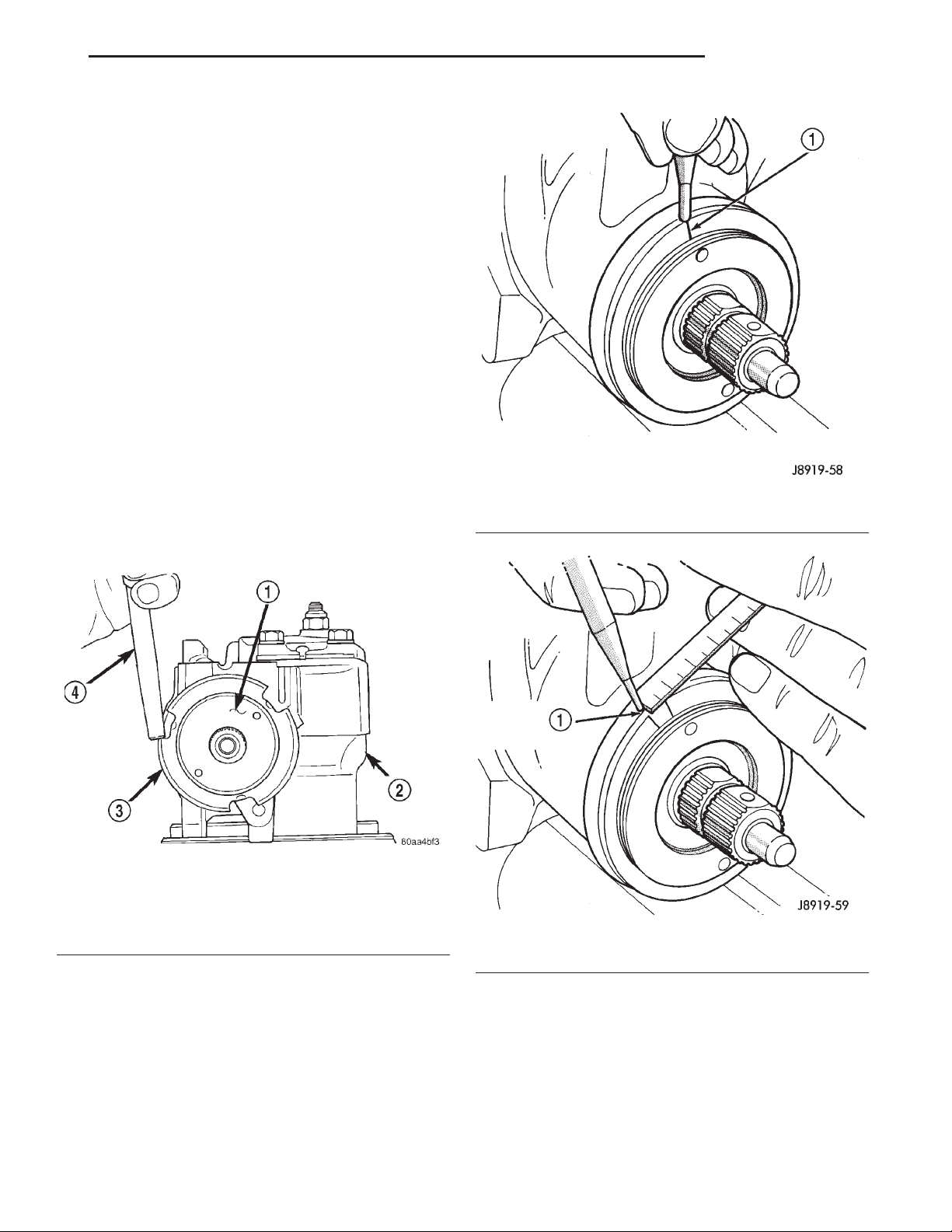
Fig. 24 Alignment Marking On Housing
(2) Remove adjuster plug locknut (Fig. 23).
(3) Rotate the stub shaft back and forth with a 12
point socket to drain the remaining fluid.
1 – INDEX
Fig. 23 Adjuster Lock Nut
1 – ADJUSTER NUT
2 – STEERING GEAR
3 – LOCK NUT
4 – PUNCH
(4) Turn the adjuster in with Spanner Wrench
C-4381. Tighten the plug and thrust bearing in the
housing until firmly bottomed in the housing about
34 N·m (25 ft. lbs.).
(5) Place an index mark on the housing even with
one of the holes in adjuster plug (Fig. 24).
(6) Measure back (counterclockwise) 5.08 mm (0.20
in) and mark housing (Fig. 25).
Fig. 25 Second Marking On Housing
1 – REFERENCE MARK
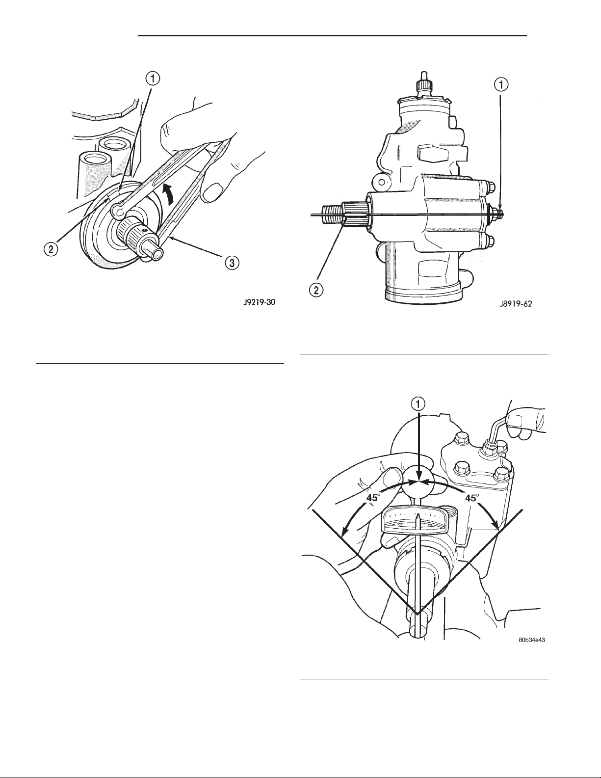
(7) Rotate adjustment cap back (counterclockwise)
with spanner wrench until hole is aligned with the
second mark (Fig. 26).
(8) Install and tighten locknut to 108 N·m (80 ft.
lbs.). Be sure adjustment cap does not turn while
tightening the locknut.
Page 20
19 - 20 STEERING XJ
ADJUSTMENTS (Continued)
Fig. 26 Aligning To The Second Mark
1 – FIRST MARK
2 – SECOND MARK
3 – SPANNER WRENCH
OVER-CENTER
NOTE: Before performing this procedure, the worm
bearing preload adjustment must be performed.
(1) Rotate the stub shaft with a 12 point socket
from stop to stop and count the number of turns.
(2) Starting at either stop, turn the stub shaft
back 1/2 the total number of turns. This is the center
of the gear travel (Fig. 27).
(3) Place the torque wrench in the vertical position
on the stub shaft. Rotate the wrench 45 degrees each
side of the center and record the highest rotational
torque in this range (Fig. 28). This is the Over-Center Rotating Torque.
NOTE: The stub shaft must rotate smoothly without
sticking or binding.
(4) Rotate the stud shaft between 90° and 180° to
the left of center and record the left off-center preload. Repeat this to the right of center and record the
right off-center preload. The average of these two
recorded readings is the Preload Rotating Torque.
(5) The Over-Center Rotating Torque should be
0.40-0.70 N·m (3-7 in. lbs.) higher than the Preload
Rotating Torque.
(6) If an adjustment to the Over-Center Rotating
Torque is necessary, first loosen the adjuster lock
nut. Then turn the pitman shaft adjuster screw back
Fig. 27 Steering Gear Centered
1 – ADJUSTMENT SCREW
2 – MASTER SPLINE
(COUNTERCLOCKWISE) until fully extended, then
turn back in (CLOCKWISE) one full turn.
Fig. 28 Checking Over-center Rotation Torque
1 – CENTER
(7) Remeasure Over-Center Rotating Torque. If
necessary turn the adjuster screw and repeat mea-
Page 21
XJ STEERING 19 - 21
ADJUSTMENTS (Continued)
surement until correct Over-Center Rotating Torque
is reached.
NOTE: To increase the Over-Center Rotating Torque
turn the screw CLOCKWISE.
(8) Prevent the adjuster screw from turning while
tightening adjuster lock nut. Tighten the adjuster
lock nut to 49 N·m (36 ft. lbs.).
SPECIFICATIONS
POWER STEERING GEAR
Steering Gear
Type .................... Recirculating Ball
Gear Ratio
RHD............................... 14:1
LHD ............................... 14:1
Worm Shaft Bearing
Preload .......... 0.45–1.13 N·m (4–10 in. lbs.)
Pitman Shaft Overcenter Drag
New Gear (under 400 miles) ..... 0.45–0.90 N·m
(4–8 in. lbs.) + Worm Shaft Preload
Used Gear (over 400 miles) ....... 0.5–0.6 N·m
(4–5 in. lbs.) + Worm Shaft Preload
SPECIAL TOOLS
POWER STEERING GEAR
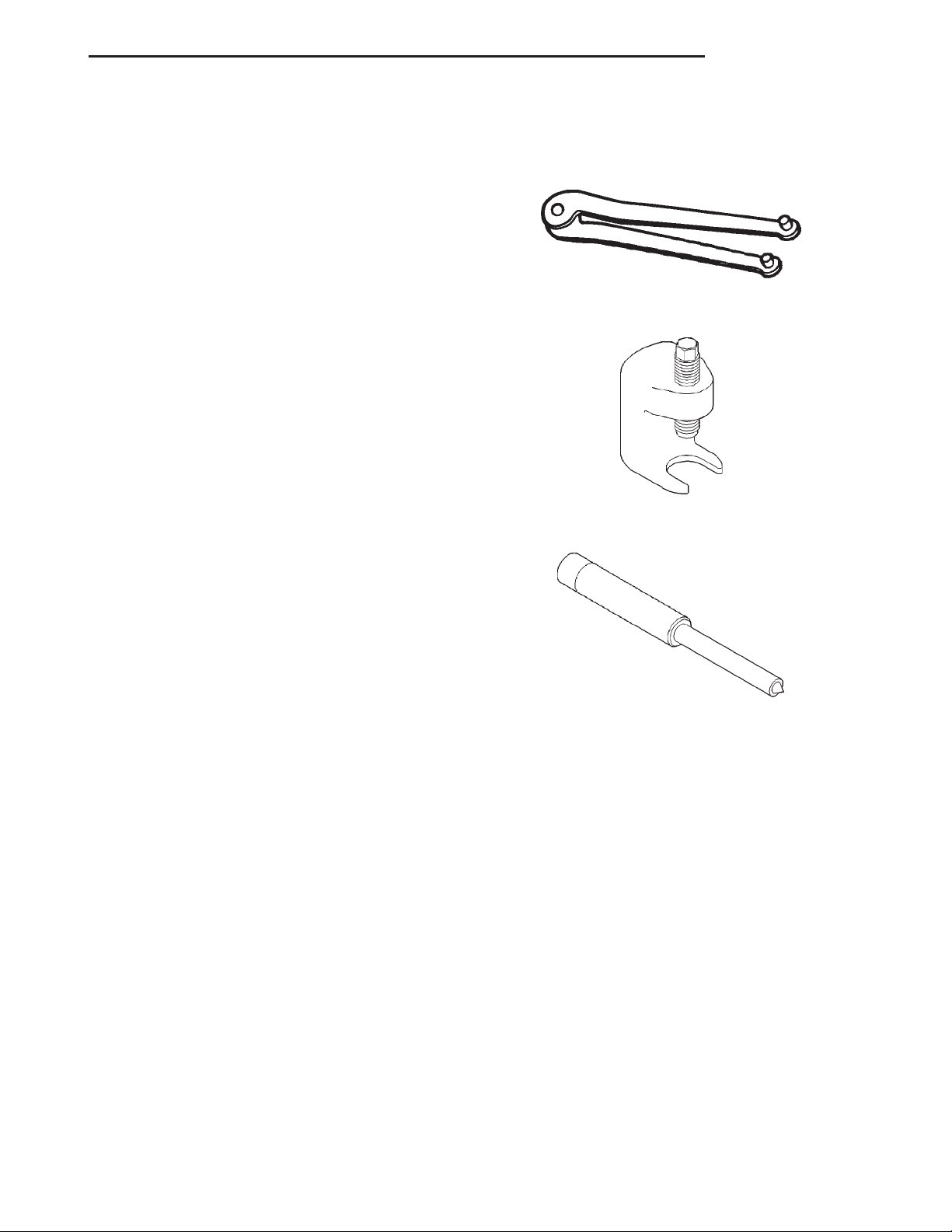
Remover/Installer, Steering Plug C-4381
Remover, Pitman Arm C-4150A
TORQUE CHART
DESCRIPTION TORQUE
Power Steering Gear
Adjustment Cap Locknut . . . 108 N·m (80 ft. lbs.)
Adjustment Screw Locknut . . 49 N·m (36 ft. lbs.)
Gear to Frame Bolts ....... 95N·m(70ft.lbs.)
Pitman Shaft Nut ....... 251N·m(185 ft. lbs.)
Rack Piston Plug ......... 102N·m(75ft.lbs.)
Side Cover Bolts .......... 60N·m(44ft.lbs.)
Pressure Line ............. 28N·m(21ft.lbs.)
Return Line .............. 28N·m(21ft.lbs.)
Return Guide Clamp Bolt . . . 58 N·m (43 ft. lbs.)
Remover/Installer Steering Rack Piston C-4175
Page 22
19 - 22 STEERING XJ
STEERING LINKAGE
TABLE OF CONTENTS
page page
DESCRIPTION AND OPERATION
STEERING LINKAGE ......................22
SERVICE PROCEDURES
STEERING LINKAGE ......................23
REMOVAL AND INSTALLATION
TIEROD...............................23
PITMAN ARM............................24
DESCRIPTION AND OPERATION
STEERING LINKAGE
DESCRIPTION
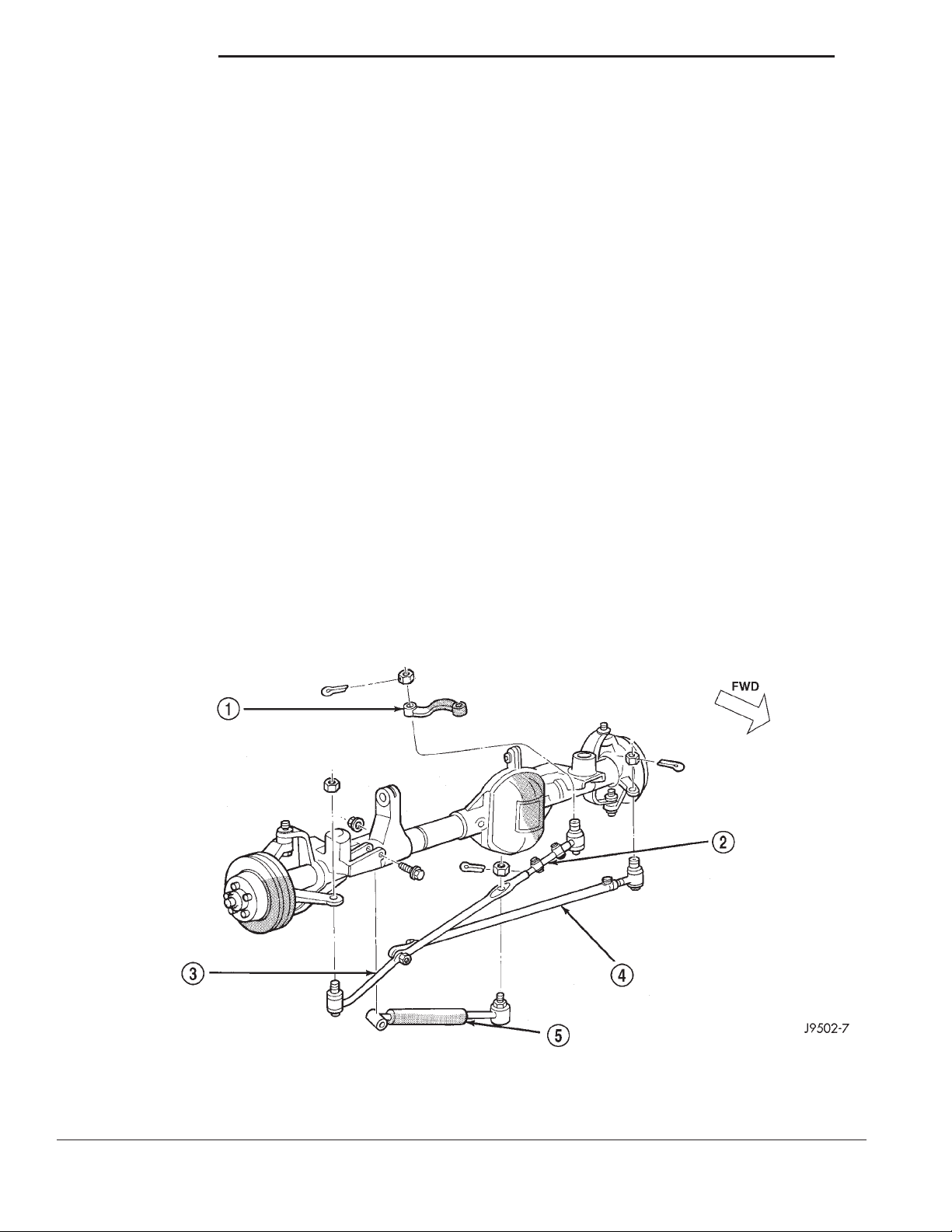
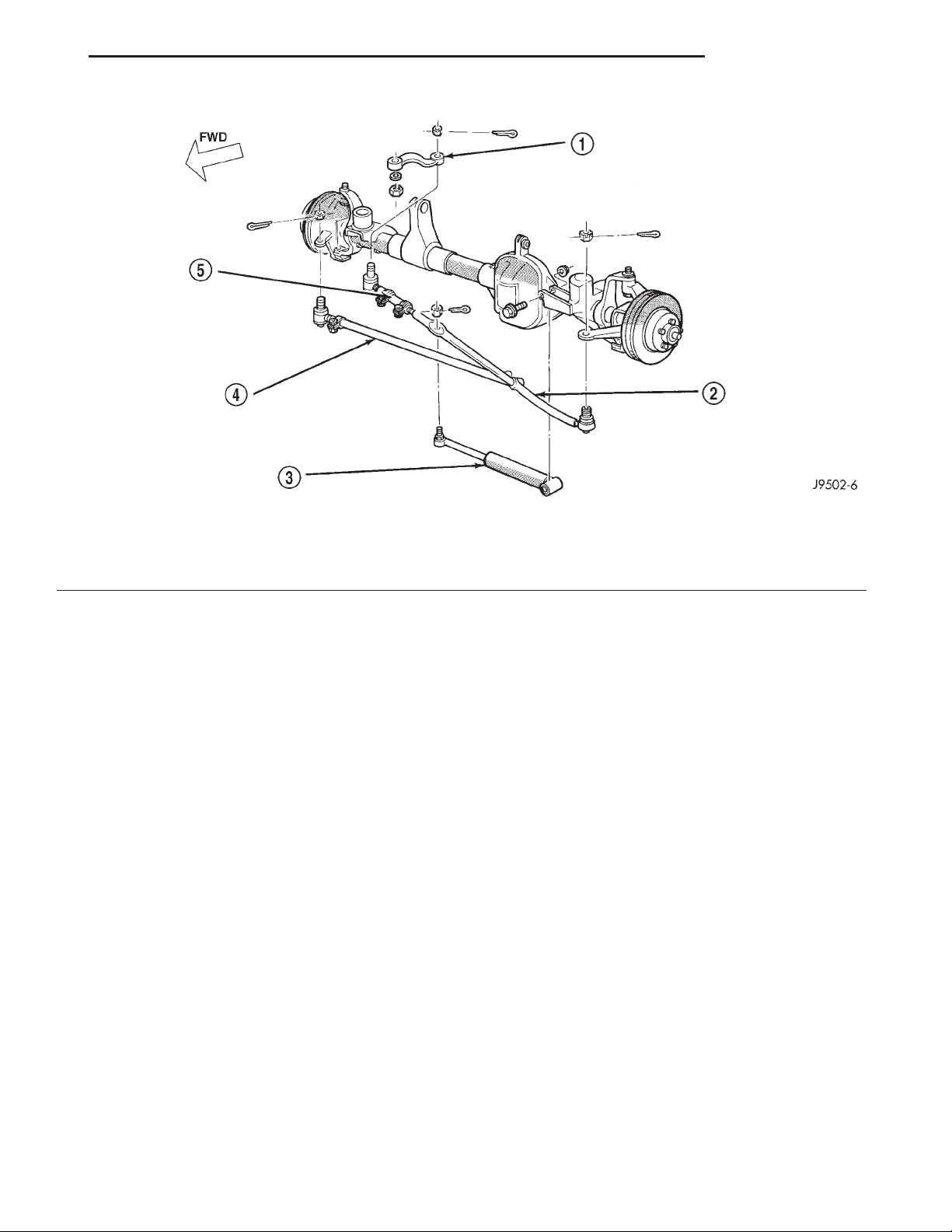
The steering linkage consist of a pitman arm, drag
link, tie rod, tie rod ends and a steering damper (Fig.
1) and (Fig. 2). The service procedures and torque
DRAG LINK .............................24
STEERING DAMPER ......................25
SPECIFICATIONS
TORQUE CHART .........................25
SPECIAL TOOLS
STEERING LINKAGE ......................25
specifications are the same for LHD and RHD vehicles.
CAUTION: Components attached with a nut and
cotter pin must be torqued to specification. Then if
the slot in the nut does not line up with the cotter
pin hole, tighten nut until it is aligned. Never loosen
the nut to align the cotter pin hole.
1 – PITMAN ARM
2 – ADJUSTMENT SLEEVE
3 – DRAG LINK
Fig. 1 Steering Linkage—LHD
4 – TIE ROD
5 – STEERING DAMPENER
Page 23
XJ STEERING 19 - 23
DESCRIPTION AND OPERATION (Continued)
Fig. 2 Steering Linkage—RHD
1 – PITMAN ARM
2 – DRAG LINK
3 – STEERING DAMPNER
SERVICE PROCEDURES
STEERING LINKAGE
The tie rod end and ball stud seals should be
inspected during all oil changes. If a seal is damaged,
it should be replaced. Before installing a new seal,
inspect ball stud at the throat opening. Check for
lubricant loss, contamination, ball stud wear or corrosion. If these conditions exist, replace the tie rod. A
replacement seal can be installed if lubricant is in
good condition. Otherwise, a complete replacement
ball stud end should be installed.
CAUTION: If any steering components are replaced
or serviced an alignment must be performed, to
ensure the vehicle meets all alignment specifications.
CAUTION: Components attached with a nut and
cotter pin must be torqued to specification. Then if
the slot in the nut does not line up with the cotter
pin hole, tighten nut until it is aligned. Never loosen
the nut to align the cotter pin hole.
4 – TIE ROD
5 – ADJUSTMENT SLEEVE
REMOVAL AND INSTALLATION
TIE ROD
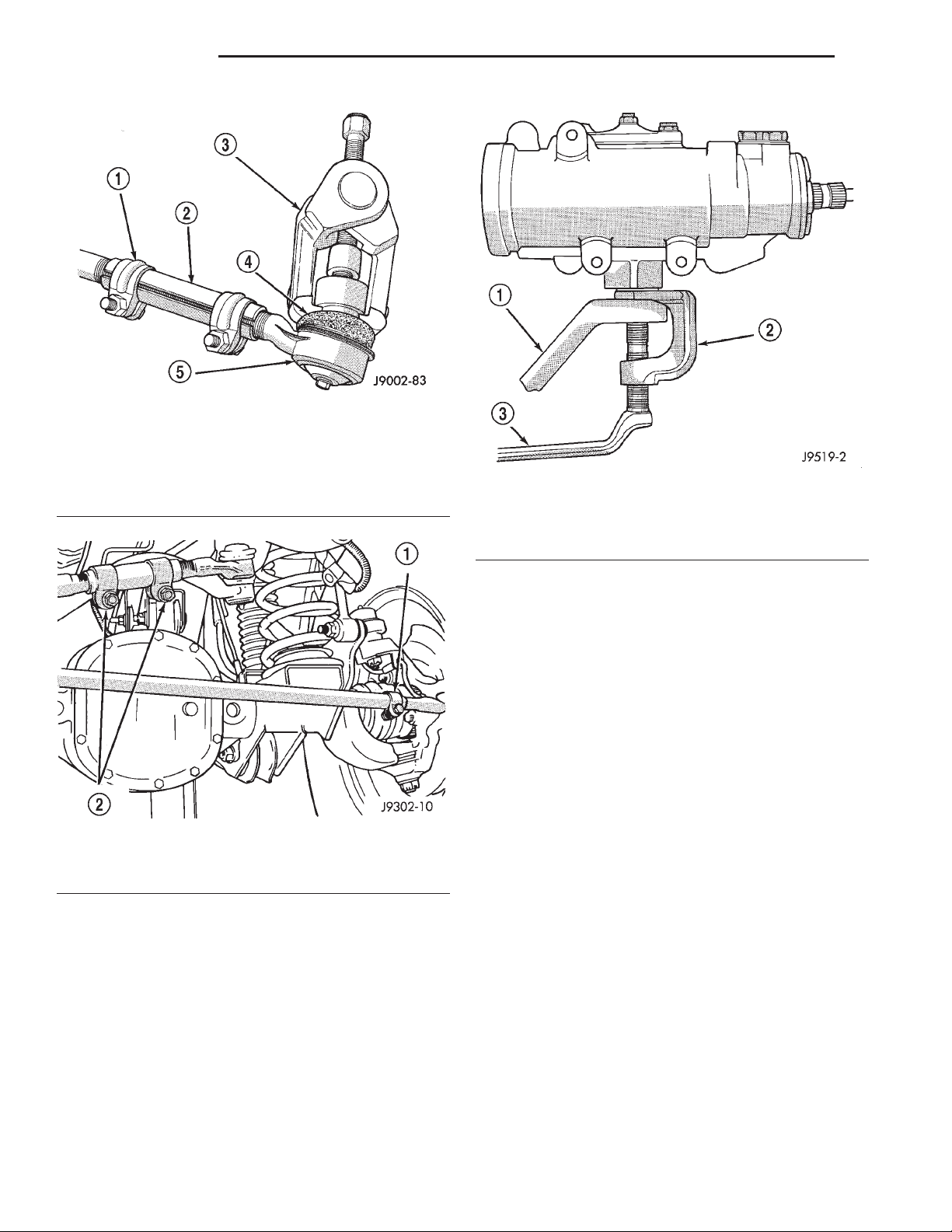
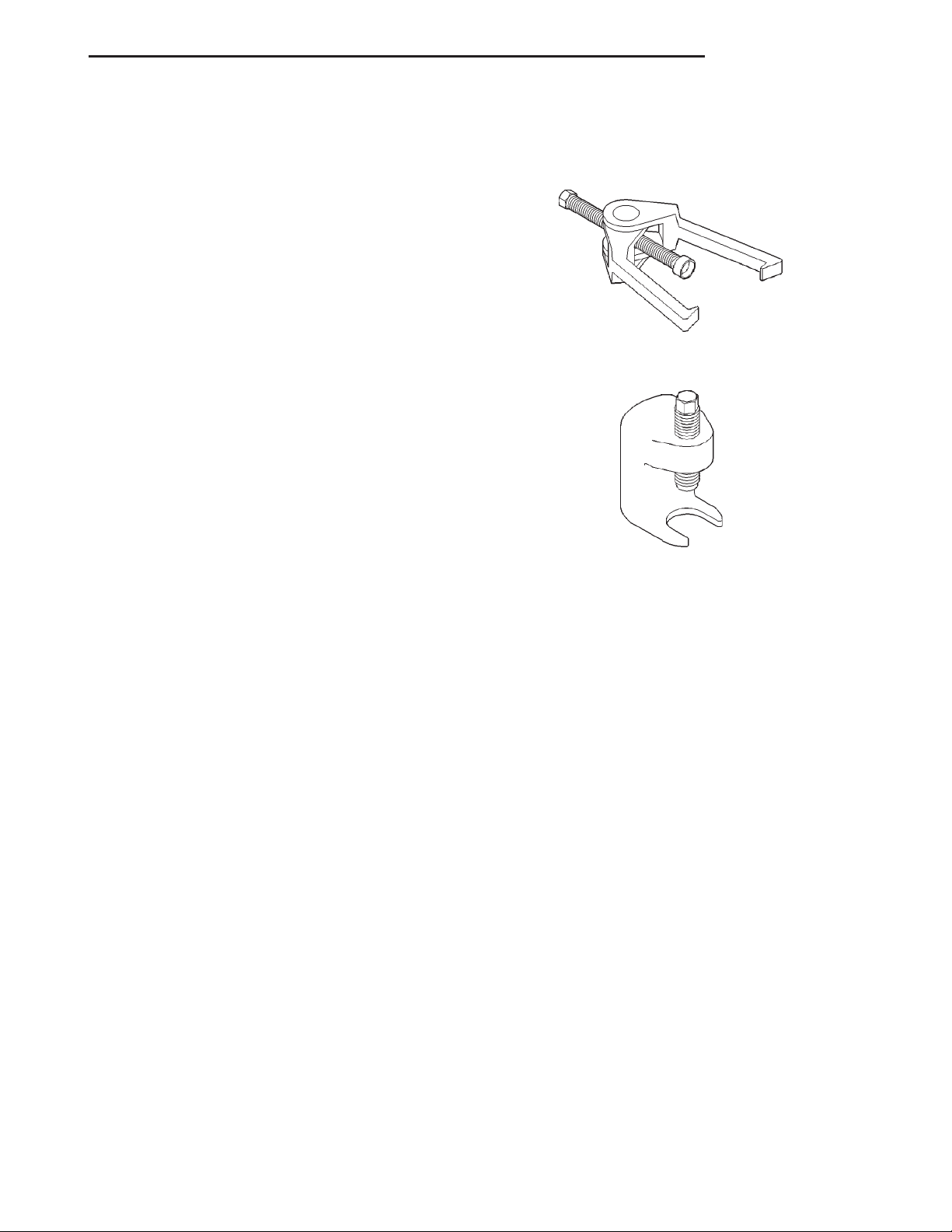
CAUTION: Use a Puller tool C-3894-A for tie rod
removal. Failure to use this tool could damage the
ball stud and seal (Fig. 3).
REMOVAL
(1) Remove the cotter pins and nuts at the tie rod
ball studs and drag link.
(2) Loosen the ball studs with a puller tool to
remove the tie rod.
(3) Loosen clamp bolts and unthread the tie rod
end from the tube.
INSTALLATION
(1) Thread the tie rod end into the tube and position the clamp to it’s original position (Fig. 4).
Tighten the clamp bolts to 27 N·m (20 ft. lbs.).
(2) Install the tie rod on the drag link and steering
knuckle. Install the retaining nuts.
(3) Tighten the ball stud nut on the steering
knuckle to 47 N·m (35 ft. lbs.). Tighten the ball stud
nut to drag link to 74 N·m (55 ft. lbs.). Install new
cotter pins.
Page 24
19 - 24 STEERING XJ
REMOVAL AND INSTALLATION (Continued)
Fig. 3 Ball Stud Puller
1 – CLAMP
2 – ADJUSTMENT SLEEVE
3 – PULLER TOOL C-3894–A
4 – SEAL
5 – TIE-ROD END
1 – PITMAN ARM
2 – SPECIAL TOOL C-4150-A
3 – WRENCH
Fig. 5 Pitman Arm Puller
Fig. 4 Tie Rod/Drag Link Clamps
1 – TIE ROD CLAMP
2 – DRAG LINK CLAMPS
PITMAN ARM
REMOVAL
(1) Remove the cotter pin and nut from the drag
link at the pitman arm.
(2) Remove the drag link ball stud from the pit-
man arm with a puller.
(3) Remove the nut and washer from the steering
gear shaft. Mark the pitman shaft and pitman arm
for installation reference. Remove the pitman arm
from steering gear with Puller C-4150-A (Fig. 5).
INSTALLATION
(1) Align and install the pitman arm on steering
gear shaft.
(2) Install the washer and nut on the shaft and
tighten nut to 251 N·m (185 ft. lbs.).
(3) Install drag link ball stud to pitman arm
install nut and tighten to 74 N·m (55 ft. lbs.). Install
a new cotter pin.
DRAG LINK
REMOVAL
(1) Remove cotter pins and nuts from drag link
(2) Remove the steering damper ball stud from the
drag link.
(3) Remove tie rod from drag link
(4) Remove drag link from the steering knuckle
and pitman arm.
INSTALLATION
(1) Install the drag link onto steering knuckle and
pitman arm.
(2) Install nut at steering knuckle and tighten to
47 N·m (35 ft. lbs.). Install new cotter pins.
(3) Install nut at pitman arm and tighten to 74
N·m (55 ft. lbs.). Install new cotter pins.
(4) Install tie rod onto drag link and install nut.
Tighten nut to 74 N·m (55 ft. lbs.) and install new
cotter pins.
Page 25
XJ STEERING 19 - 25
REMOVAL AND INSTALLATION (Continued)
(5) Install steering damper onto drag link and
install nut. Tighten nut to 74 N·m (55 ft. lbs.) and
install a new cotter pin.
STEERING DAMPER
REMOVAL
(1) Remove the steering damper retaining bolt
from the axle bracket.
(2) Remove the cotter pin and nut from the ball
stud at the drag link.
(3) Remove the steering damper ball stud from the
drag link with Puller C-3894-A.
INSTALLATION
(1) Install steering damper onto the axle bracket
and drag link.
(2) Install steering damper bolt in axle bracket
and tighten nut to 75 N·m (55 ft. lbs.).
(3) Install ball stud nut at the drag link and
tighten nut to 75 N·m (55 ft. lbs.). Install a new cotter pin.
SPECIFICATIONS
SPECIAL TOOLS
STEERING LINKAGE
Puller C-3894–A
Remover Pitman C-4150A
TORQUE CHART
DESCRIPTION TORQUE
Pitman Arm
Shaft ................. 251N·m(185 ft. lbs.)
Drag Link
Ball Studs ............... 74N·m(55ft.lbs.)
Clamp .................. 49N·m(36ft.lbs.)
Tie Rod Ends
Ball Studs ............... 74N·m(55ft.lbs.)
Clamp .................. 27N·m(20ft.lbs.)
Tie Rod
Ball Stud ................ 47N·m(35ft.lbs.)
Steering Damper
Frame .................. 74N·m(55ft.lbs.)
Drag Link ............... 74N·m(55ft.lbs.)
Page 26
19 - 26 STEERING XJ
STEERING COLUMN
TABLE OF CONTENTS
page page
DESCRIPTION AND OPERATION
STEERING COLUMN ......................26
REMOVAL AND INSTALLATION
STEERING COLUMN ......................26
DESCRIPTION AND OPERATION
STEERING COLUMN
DESCRIPTION
The standard non-tilt and tilt steering column has
been designed to be serviced as an assembly. The key
cylinder, switches, clock spring, trim shrouds and
steering wheel are serviced separately. On the nontilt column the upper mounting bracket is also serviced separately.
The column is mounted to the column support
bracket studs and secured by four nuts. The column
is connected to the steering gear by a one piece collapsible shaft with a coupler at each end. The couplers secure the shaft to the steering column and
steering gear.
SERVICE PRECAUTIONS
Safety goggles should be worn at all times when
working on steering columns.
To service the steering wheel, switches or airbag,
refer to Group 8M and follow all WARNINGS and
CAUTIONS.
WARNING: THE AIRBAG SYSTEM IS A SENSITIVE,
COMPLEX ELECTRO-MECHANICAL UNIT. BEFORE
ATTEMPTING TO DIAGNOSE, REMOVE OR INSTALL
THE AIRBAG SYSTEM COMPONENTS YOU MUST
FIRST DISCONNECT AND ISOLATE THE BATTERY
NEGATIVE (GROUND) CABLE. THEN WAIT TWO
MINUTES FOR THE SYSTEM CAPACITOR TO DISCHARGE. FAILURE TO DO SO COULD RESULT IN
ACCIDENTAL DEPLOYMENT OF THE AIRBAG AND
POSSIBLE PERSONAL INJURY. THE FASTENERS,
SCREWS, AND BOLTS, ORIGINALLY USED FOR
THE AIRBAG COMPONENTS, HAVE SPECIAL COATINGS AND ARE SPECIFICALLY DESIGNED FOR THE
AIRBAG SYSTEM. THEY MUST NEVER BE
REPLACED WITH ANY SUBSTITUTES. ANYTIME A
NEW FASTENER IS NEEDED, REPLACE WITH THE
CORRECT FASTENERS PROVIDED IN THE SERVICE
PACKAGE OR FASTENERS LISTED IN THE PARTS
BOOKS.
SPECIFICATIONS
TORQUE CHART .........................28
REMOVAL AND INSTALLATION
STEERING COLUMN
WARNING: BEFORE SERVICING THE STEERING
COLUMN THE AIRBAG SYSTEM MUST BE DISARMED. REFER TO GROUP 8M RESTRAINT SYSTEMS FOR SERVICE PROCEDURES. FAILURE TO
DO SO MAY RESULT IN ACCIDENTAL DEPLOYMENT OF THE AIRBAG AND POSSIBLE PERSONAL
INJURY.
CAUTION: Keep clock spring from turning during
removal and installation. Failure to do so may damage the clock spring.
REMOVAL
(1) Position front wheels straight ahead.
(2) Remove and isolate the negative battery
ground cable.
(3) Remove the airbag, refer to Group 8M
Restraint Systems for service procedures.
NOTE: If equipped with cruise control, disconnect
clock spring harness from cruise switch harness on
the steering wheel.
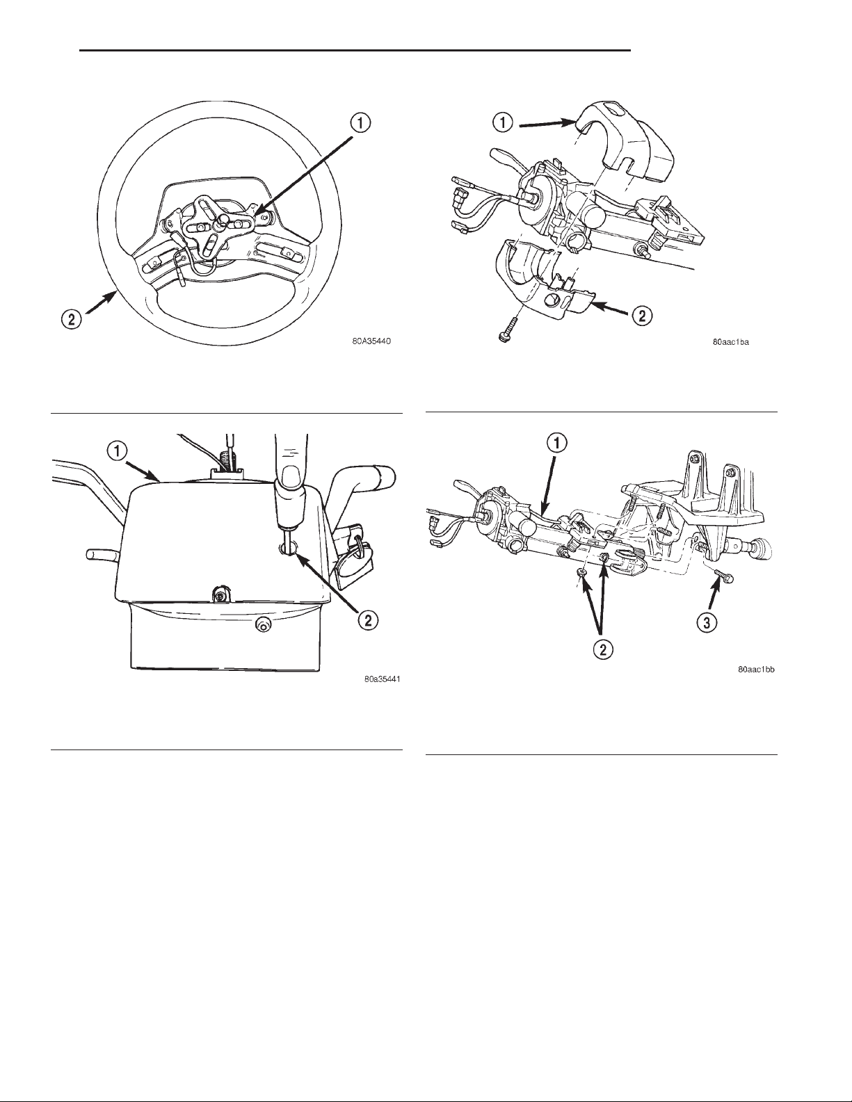
(4) Remove the steering wheel with an appropriate
puller (Fig. 1).
CAUTION: Ensure the puller bolts are fully engaged
into the steering wheel and not into the clockspring, before attempting to remove the wheel. Failure to do so may damage the steering wheel.
(5) Turn ignition cylinder to the on position and
remove cylinder by pressing release through lower
shroud access hole (Fig. 2).
Page 27
XJ STEERING 19 - 27
REMOVAL AND INSTALLATION (Continued)
Fig. 1 Steering Wheel
1 – PULLER
2 – STEERING WHEEL
Fig. 2 Key Cylinder Release Access Hole
1 – LOWER SHROUD
2 – RELEASE ACCESS HOLE
Fig. 3 Column Shrouds
1 – UPPER SHROUD
2 – LOWER SHROUD
Fig. 4 Tilt Steering Column Mounting
1 – STEERING COLUMN
2 – MOUNTING NUTS
3 – COUPLER BOLT
(6) Remove knee blocker cover and knee blocker,
Refer to Group 8E Instrument Panel Systems.
(7) Remove screws from the lower column shroud
(Fig. 3) and remove lower shroud.
(8) Remove the steering coupler bolt and column
mounting nuts (Fig. 4) then lower column off the
mounting stud.
(9) Remove upper column shroud (Fig. 3).
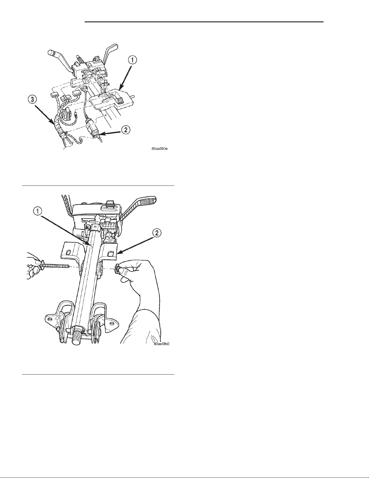
(10) Disconnect and remove the wiring harness
from the column (Fig. 5).
NOTE: If vehicle is equipped with automatic transmission, remove shifter interlock cable. Refer to
Group 21 Transmission and Transfer Case for procedure.
(11) Remove column.
(12) Remove nut and bolt from the upper column
mounting bracket on non-tilt column (Fig. 6). Remove
the bracket from the column and note the mount-
ing location and orientation of the bracket..
(13) Remove clock spring, switches, (SKIM if
equipped) and ignition key cylinder, refer to Group 8
Electrical for service procedures.
INSTALLATION
(1) Install upper column mounting bracket on nontilt column. Install the mounting bolt and tighten the
nut to 17 N·m (150 in. lbs.).
(2) Install switches, refer to Group 8 Electrical for
service procedures.
Page 28
19 - 28 STEERING XJ
REMOVAL AND INSTALLATION (Continued)
(4) Install column harness and connect harness to
switches.
NOTE: If vehicle is equipped with automatic transmission install shifter interlock cable. Refer to
Group 21 Transmission and Transfer Case for
installation and adjustment.
(5) Install upper column shrouds.
(6) Install column onto the mounting studs.
(7) Install mounting nuts and tighten to 23 N·m
(17 ft. lbs.).
(8) Install steering column coupler bolt and tighten
to 49 N·m (36 ft. lbs.).
(9) Center the clock spring (if necessary) and
install it on the column, refer to Group 8 Electrical
Fig. 5 Steering Column Harness
1 – STEERING COLUMN
2 – INTERLOCK CABLE
3 – COLUMN HARNESS
for service procedures.
(10) Install lower column shroud and install
mounting screws.
(11) Install ignition cylinder.
(12) Install knee blocker and knee blocker cover,
Refer to Group 8E Instrument Panel Systems.
(13) Install steering wheel and tighten nut to 54
N·m (40 ft. lbs.).
Fig. 6 Non-Tilt Column
1 – NON-TILT COLUMN
2 – UPPER BRACKET
(3) Align and install column into the steering cou-
pler.
NOTE: If equipped with cruise control, connect
clock spring harness to cruise switch harness on
the steering wheel.
(14) Install airbag, refer to Group 8M Restraint
Systems for service procedures.
(15) Install negative battery terminal.
SPECIFICATIONS
TORQUE CHART
DESCRIPTION TORQUE
Tilt Steering Column
Steering Wheel Nut ........ 54N·m(40ft.lbs.)
Mounting Nuts ........... 23N·m(17ft.lbs.)
Coupler Bolt .............. 49N·m(36ft.lbs.)
Non-Tilt Steering Column
Steering Wheel Nut ........ 54N·m(40ft.lbs.)
Mounting Nuts ........... 23N·m(17ft.lbs.)
Coupler Bolt .............. 49N·m(36ft.lbs.)
Upper Bracket Nut ....... 17N·m(150 in. lbs.)
 Loading...