

Page 1
XJ FUEL SYSTEM—2.5L DIESEL ENGINE 14 - 1
FUEL SYSTEM—2.5L DIESEL ENGINE
CONTENTS
page page
FUEL DELIVERY SYSTEM—
2.5L DIESEL ENGINE ..................... 2
FUEL INJECTION SYSTEM—
2.5L DIESEL ENGINE .................... 23
GENERAL INFORMATION
page page
GENERAL INFORMATION
FUEL REQUIREMENTS—2.5L DIESEL ......... 1
GENERAL INFORMATION
FUEL SHUTDOWN SOLENOID
The fuel shutdown solenoid is controlled and
operated by the MSA.
The fuel shutdown (shut-off) solenoid is used to
electrically shut off the diesel fuel supply to the highpressure fuel injection pump. The solenoid is
mounted to the rear of the injection pump.
The solenoid controls starting and stopping of the
engine regardless of the position of the accelerator
GENERAL INFORMATION ................... 1
INDEX
FUEL SHUTDOWN SOLENOID .............. 1
pedal. When the ignition (key) switch is OFF, the
solenoid is shut off and fuel flow is not allowed to the
fuel injection pump. When the key is placed in the
ON or START positions, fuel supply is allowed at the
injection pump.
FUEL REQUIREMENTS—2.5L DIESEL
Premium quality diesel fuel with a minimum Cet-
ane rating of 50 or higher is required.
Page 2

14 - 2 FUEL SYSTEM—2.5L DIESEL ENGINE XJ
FUEL DELIVERY SYSTEM—2.5L DIESEL ENGINE
INDEX
page page
DESCRIPTION AND OPERATION
FUEL DRAIN TUBES ...................... 6
FUEL FILTER/WATER SEPARATOR ........... 3
FUEL GAUGE SENDING UNIT ............... 3
FUEL HEATER ........................... 6
FUEL HEATER RELAY ..................... 7
FUEL INJECTION PUMP ................... 4
FUEL INJECTORS ........................ 4
FUEL SHUTDOWN SOLENOID .............. 3
FUEL SYSTEM PRESSURE WARNING ........ 2
FUEL TANK ............................. 2
FUEL TANK MODULE ..................... 3
FUEL TUBES/LINES/HOSES AND CLAMPS—
LOW-PRESSURE TYPE .................. 5
HIGH-PRESSURE FUEL LINES .............. 6
INTRODUCTION .........................2
QUICK-CONNECT FITTINGS—LOW PRESSURE
TYPE ................................ 5
DIAGNOSIS AND TESTING
AIR IN FUEL SYSTEM .................... 10
FUEL HEATER RELAY TEST ............... 10
FUEL INJECTION PUMP TEST .............. 11
FUEL INJECTOR / NEEDLE MOVEMENT
SENSOR TEST ........................11
FUEL INJECTOR TEST ................... 10
FUEL SHUTDOWN SOLENOID TEST ......... 12
FUEL SUPPLY RESTRICTIONS .............11
GENERAL INFORMATION .................. 7
HIGH-PRESSURE FUEL LINE LEAK TEST ..... 12
VISUAL INSPECTION ...................... 7
SERVICE PROCEDURES
AIR BLEED PROCEDURES ................ 12
FUEL INJECTION PUMP TIMING ............ 13
REMOVAL AND INSTALLATION
ACCELERATOR PEDAL ................... 13
AIR CLEANER ELEMENT .................. 13
FUEL DRAIN TUBES ..................... 14
FUEL FILTER/WATER SEPARATOR .......... 14
FUEL HEATER .......................... 15
FUEL HEATER RELAY .................... 15
FUEL INJECTION PUMP .................. 15
FUEL INJECTORS ....................... 19
FUEL LEVEL SENSOR .................... 15
FUEL RESERVOIR MODULE ............... 21
FUEL TANK ............................ 20
HIGH-PRESSURE LINES .................. 22
SPECIFICATIONS
FUEL INJECTOR FIRING SEQUENCE ........ 22
FUEL SYSTEM PRESSURE ................ 22
FUEL TANK CAPACITY ................... 22
IDLE SPEED ........................... 22
DESCRIPTION AND OPERATION
INTRODUCTION
This Fuel Delivery section will cover components
not controlled by the PCM. For components controlled by the PCM, refer to the Fuel Injection System—2.5L Diesel Engine section of this group.
The fuel heater relay, fuel heater and fuel gauge
are not operated by the PCM. These components are
controlled by the ignition (key) switch. All other fuel
system electrical components necessary to operate
the engine are controlled or regulated by the PCM.
FUEL SYSTEM PRESSURE WARNING
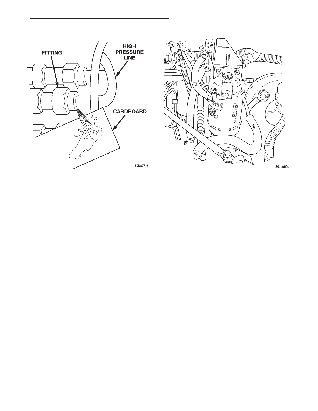
WARNING: HIGH–PRESSURE FUEL LINES DELIVER
DIESEL FUEL UNDER EXTREME PRESSURE FROM
THE INJECTION PUMP TO THE FUEL INJECTORS.
THIS MAY BE AS HIGH AS 45,000 KPA (6526 PSI).
USE EXTREME CAUTION WHEN INSPECTING FOR
HIGH–PRESSURE FUEL LEAKS. INSPECT FOR
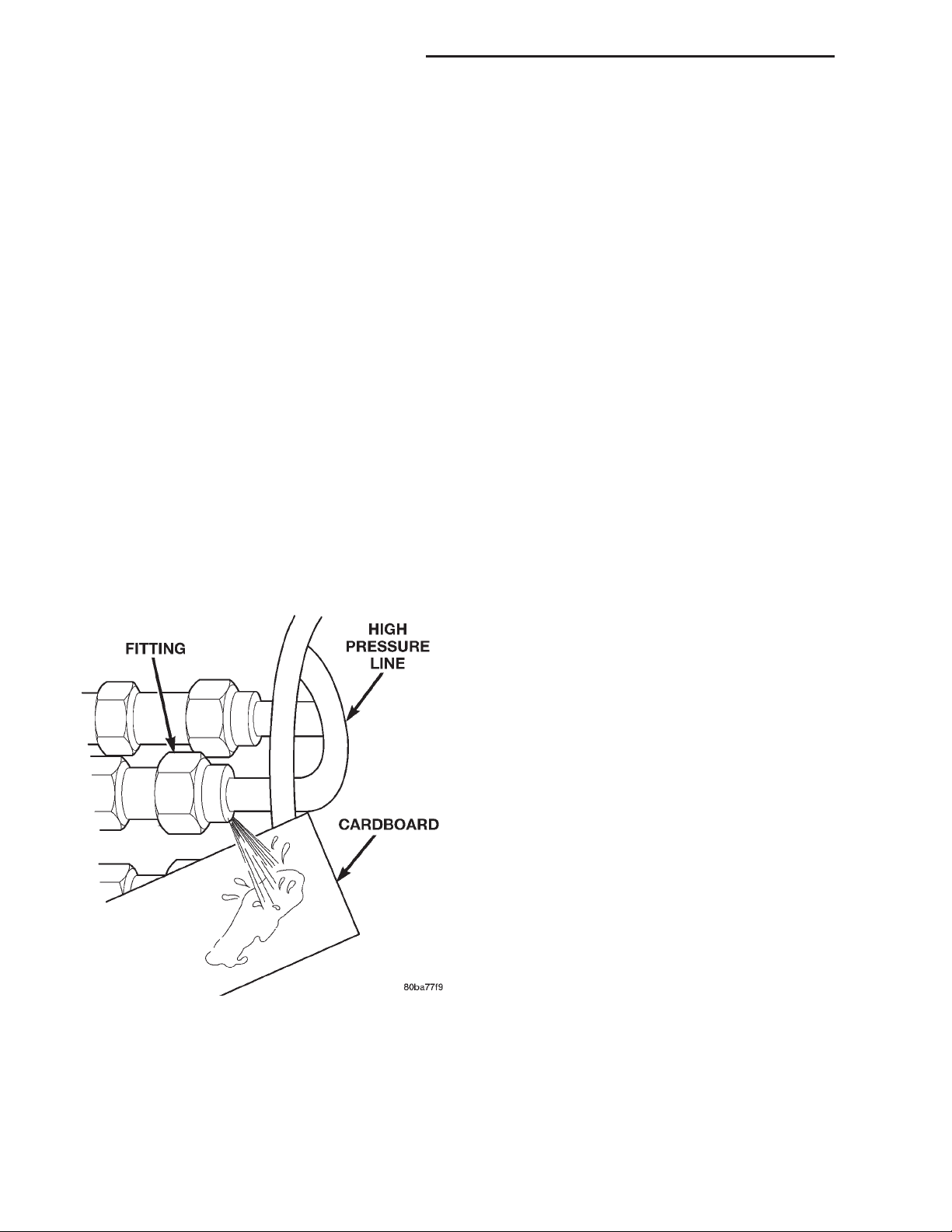
HIGH–PRESSURE FUEL LEAKS WITH A SHEET OF
CARDBOARD (Fig. 1). HIGH FUEL INJECTION
PRESSURE CAN CAUSE PERSONAL INJURY IF
CONTACT IS MADE WITH THE SKIN.
FUEL TANK
The fuel tank and tank mounting used with the
diesel powered engine is the same as used with gasoline powered models, although the fuel tank module
is different.
The fuel tank contains the fuel tank module and
two rollover valves. Two fuel lines are routed to the
fuel tank module. One line is used for fuel supply to
the fuel filter/water separator. The other is used to
return excess fuel back to the fuel tank.
The fuel tank module contains the fuel gauge electrical sending unit. An electrical fuel pump is not
used with the diesel engine.
Page 3
XJ FUEL SYSTEM—2.5L DIESEL ENGINE 14 - 3
DESCRIPTION AND OPERATION (Continued)
Fig. 1 Typical Fuel Pressure Test at Injector Fig. 2 Fuel Filter/Water Separator Location
FUEL TANK MODULE
An electric fuel pump is not attached to the fuel
tank module for diesel powered engines. Fuel is
siphoned by the fuel injection pump.
The fuel tank module is installed in the top of the
fuel tank. The fuel tank module contains the following components:
• Fuel reservoir
• A separate in-tank fuel filter
• Electric fuel gauge sending unit
• Fuel supply line connection
• Fuel return line connection
FUEL GAUGE SENDING UNIT
The fuel gauge sending unit is attached to the side
of the fuel pump module. The sending unit consists of
a float, an arm, and a variable resistor (track). The
track is used to send an electrical signal used for fuel
gauge operation.
As the fuel level increases, the float and arm move
up. This decreases the sending unit resistance, causing the PCM to send a signal to the fuel gauge on the
instrument panel to read full. As the fuel level
decreases, the float and arm move down. This
increases the sending unit resistance, causing the
PCM to send a signal to the fuel gauge on the instrument panel to read empty.
FUEL FILTER/WATER SEPARATOR
The fuel filter/water separator assembly is located
in the engine compartment near the strut tower (Fig.
2).
The combination fuel filter/water separator protects the fuel injection pump by helping to remove
water and contaminants from the fuel. Moisture collects at the bottom of the filter/separator in a plastic
bowl.
The fuel filter/water separator assembly contains
the fuel filter, fuel heater element, and fuel drain
valve.
For information on the fuel heater, refer to Fuel
Heater in this group.
Refer to the maintenance schedules in Group 0 in
this manual for the recommended fuel filter replacement intervals.
For periodic draining of water from the bowl, refer
to Fuel Filter/Water Separator Removal/Installation
in this group.
FUEL SHUTDOWN SOLENOID
The fuel shutdown solenoid is controlled and
operated by the MSA.
The fuel shutdown (shut-off) solenoid is used to
electrically shut off the diesel fuel supply to the highpressure fuel injection pump. The solenoid is
mounted to the rear of the injection pump.
The solenoid controls starting and stopping of the
engine regardless of the position of the accelerator
pedal. When the ignition (key) switch is OFF, the
solenoid is shut off and fuel flow is not allowed to the
fuel injection pump. When the key is placed in the
ON or START positions, fuel supply is allowed at the
injection pump.
Page 4
14 - 4 FUEL SYSTEM—2.5L DIESEL ENGINE XJ
DESCRIPTION AND OPERATION (Continued)
FUEL INJECTION PUMP
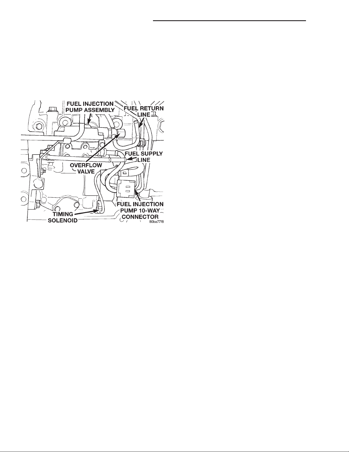
The fuel injection pump is a mechanical distributor–type, Bosch VP36 series (Fig. 3). A gear on the
end of the injection pump shaft meshes with the
drive gear at the front of engine. The pump is
mechanically timed to the engine. The MSA can
make adjustments to the timing of the injection
pump.
Fig. 3 Fuel Injection Pump
The injection pump contains the fuel shutdown
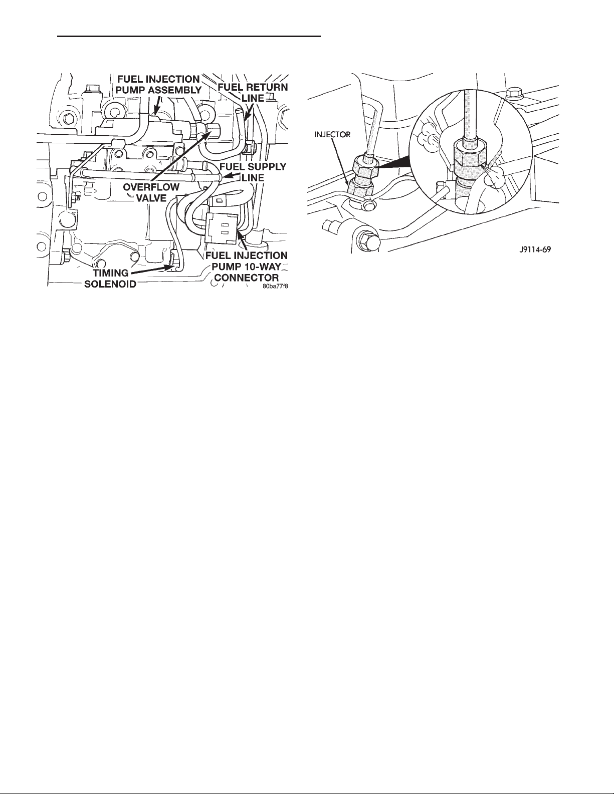
solenoid, fuel temperature sensor, control sleeve sensor, fuel quantity actuator and the fuel timing solenoid (Fig. 3).
In the electronically controlled injection pump, the
pump plunger works the same as the pump plunger
in a mechanically controlled injection pump, but the
amount of fuel and the time the fuel is injected is
controlled by the vehicle’s MSA, instead of by a
mechanical governor assembly. A solenoid controlled
by the MSA is used in place of the mechanical governor assembly, and it moves a control sleeve inside the
pump that regulates the amount of fuel being
injected. There is no mechanical connection between
the accelerator pedal and the electronically controlled
injection pump. Instead, a sensor connected to the
accelerator pedal sends a signal to the MSA that represents the actual position of the accelerator pedal.
The MSA uses this input, along with input from
other sensors to move the control sleeve to deliver
the appropriate amount of fuel. This system is known
as “Drive-By-Wire”.
The actual time that the fuel is delivered is very
important to the diesel combustion process. The MSA
monitors outputs from the engine speed sensor (flywheel position in degrees), and the fuel injector sensor (mechanical movement within the #1 cylinder
fuel injector). Outputs from the Accelerator Pedal
Position sensor, engine speed sensor (engine rpm)
and engine coolant temperature sensor are also used.
The MSA will then compare its set values to these
outputs to electrically adjust the amount of fuel timing (amount of advance) within the injection pump.
This is referred to as “Closed Loop” operation. The
MSA monitors fuel timing by comparing its set value
to when the injector #1 opens. If the value is greater
than a preset value a fault will be set.
Actual electric fuel timing (amount of advance) is
accomplished by the fuel timing solenoid mounted to
the bottom of the injection pump (Fig. 3). Fuel timing
will be adjusted by the MSA, which controls the fuel
timing solenoid.
An overflow valve is attached into the fuel return
line at the rear of the fuel injection pump (Fig. 3).
This valve serves two purposes. One is to ensure that
a certain amount of residual pressure is maintained
within the pump when the engine is switched off.
This will prevent the fuel timing mechanism within
the injection pump from returning to its zero position. The other purpose is to allow excess fuel to be
returned to the fuel tank through the fuel return
line. The pressure values within this valve are preset
and can not be adjusted.
The fuel injection pump supplies high–pressure
fuel of approximately 45,000 kPa (6526 psi) to each
injector in precise metered amounts at the correct
time.
For mechanical injection pump timing, refer to
Fuel Injection Pump Timing in the Service Procedures section of this group.
FUEL INJECTORS
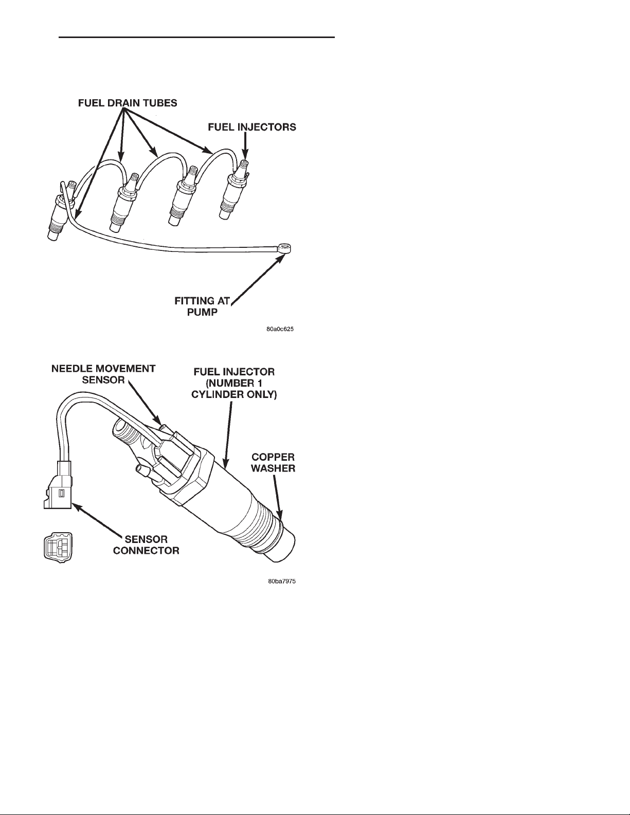
Fuel drain tubes (Fig. 4) are used to route excess
fuel back to the overflow valve at the rear of the
injection pump. This excess fuel is then returned to
the fuel tank through the fuel return line.
The injectors are connected to the fuel injection
pump by the high–pressure fuel lines. A separate
injector is used for each of the four cylinders. An
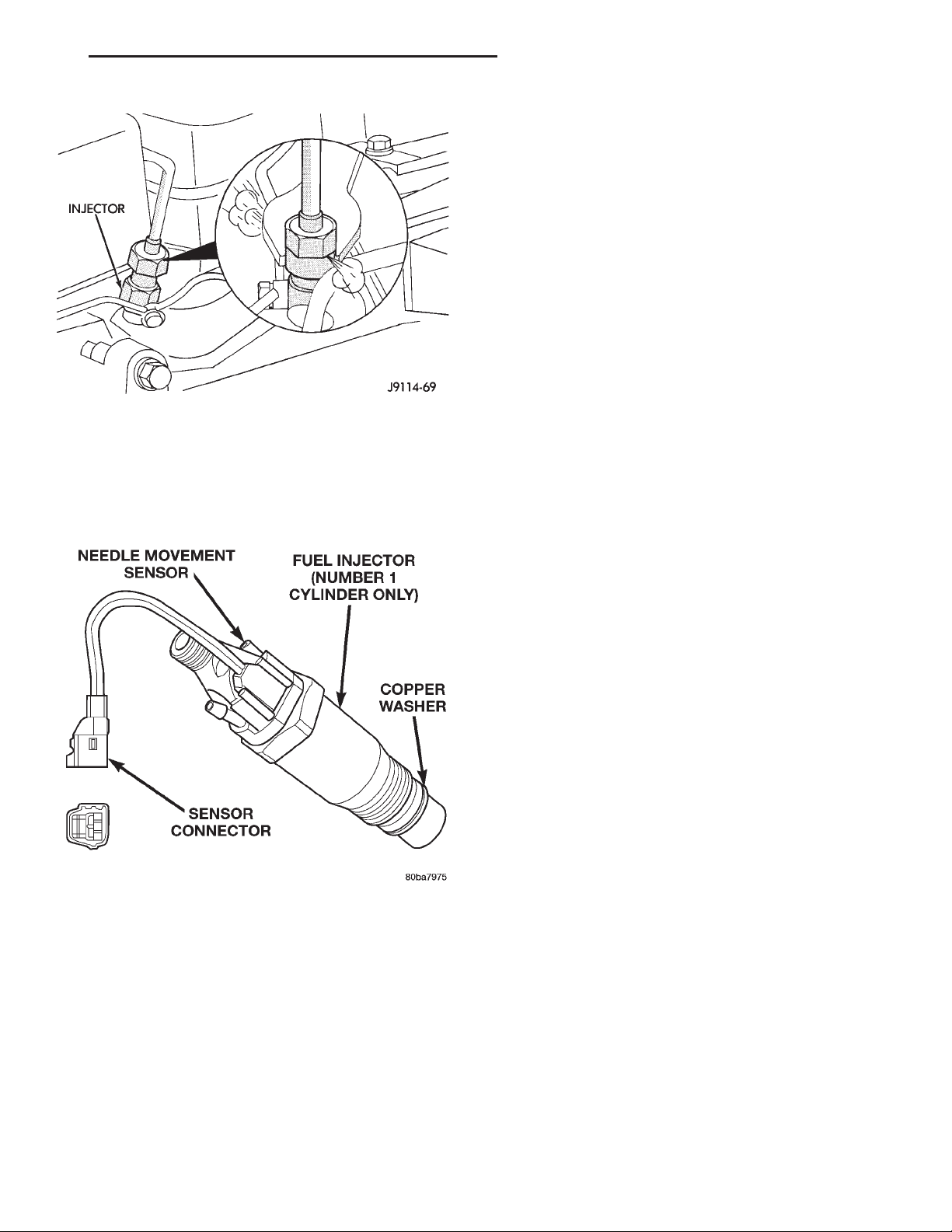
injector containing a sensor (Fig. 5) is used on the
cylinder number one injector. This injector is called
instrumented injector #1 or needle movement sensor.
It is used to tell the MSA when the #1 injector’s
internal spring-loaded valve seat has been forced
open by pressurized fuel being delivered to the cylinder, which is at the end of its compression stroke.
When the instrumented injector’s valve seat is force
open, it sends a small voltage spike pulse to the
MSA. This tells the MSA that cylinder #1 is firing. It
is not used with the other three injectors.
Fuel enters the injector at the fuel inlet (top of
injector) and is routed to the needle valve bore. When
fuel pressure rises to approximately 15,000–15,800
Page 5
XJ FUEL SYSTEM—2.5L DIESEL ENGINE 14 - 5
DESCRIPTION AND OPERATION (Continued)
A copper washer (gasket) is used at the base of
each injector (Fig. 5) to prevent combustion gases
from escaping.
Fuel injector firing sequence is 1–3–4–2.
FUEL TUBES/LINES/HOSES AND CLAMPS—
LOW-PRESSURE TYPE
Also refer to the proceeding section on Quick–Connect Fittings.
Inspect all hose connections such as clamps, couplings and fittings to make sure they are secure and
leaks are not present. The component should be
replaced immediately if there is any evidence of degradation that could result in failure.
Never attempt to repair a plastic fuel line/tube or a
quick–connect fitting. Replace complete line/tube as
necessary.
Avoid contact of any fuel tubes/hoses with other
vehicle components that could cause abrasions or
scuffing. Be sure that the fuel lines/tubes are properly routed to prevent pinching and to avoid heat
Fig. 4 Fuel Injectors and Drain Tubes
sources.
The lines/tubes/hoses are of a special construction.
If it is necessary to replace these lines/tubes/hoses,
use only original equipment type.
The hose clamps used to secure the rubber hoses
are of a special rolled edge construction. This construction is used to prevent the edge of the clamp
from cutting into the hose. Only these rolled edge
type clamps may be used in this system. All other
types of clamps may cut into the hoses and cause
fuel leaks.
Where a rubber hose is joined to a metal tube
(staked), do not attempt to repair. Replace entire
line/tube assembly.
Use new original equipment type hose clamps.
Tighten hose clamps to 2 N·m (20 in. lbs.) torque.
Fig. 5 Fuel Injector Sensor
kPa (2175–2291 psi), the needle valve spring tension
is overcome. The needle valve rises and fuel flows
through the spray holes in the nozzle tip into the
combustion chamber. The pressure required to lift
the needle valve is the injector opening pressure setting. This is referred to as the “pop-off” pressure setting.
Fuel pressure in the injector circuit decreases after
injection. The injector needle valve is immediately
closed by the needle valve spring and fuel flow into
the combustion chamber is stopped. Exhaust gases
are prevented from entering the injector nozzle by
the needle valve.
QUICK-CONNECT FITTINGS—LOW PRESSURE
TYPE
Different types of quick-connect fittings are used to
attach various fuel system components. These are: a
single-tab type, a two-tab type or a plastic retainer
ring type (Fig. 6). Refer to Quick-Connect Fittings in
the Removal/Installation section for more information.
CAUTION: The interior components (o-rings, spacers) of quick-connect fitting are not serviced separately, but new pull tabs are available for some
types. Do not attempt to repair damaged fittings or
fuel lines/tubes. If repair is necessary, replace the
complete fuel tube assembly.
Page 6
14 - 6 FUEL SYSTEM—2.5L DIESEL ENGINE XJ
DESCRIPTION AND OPERATION (Continued)
injected into the combustion chamber. This fuel
drains into the fuel drain tubes (Fig. 7) and back to
the tee banjo fitting, which is connected to the same
line as the overflow valve, which allows a variable
quantity to return to the fuel tank. The overflow
valve is calibrated to open at a preset pressure.
Excess fuel not required by the pump to maintain the
minimum pump cavity pressure is then returned
through the overflow valve and on to the fuel tank
through the fuel return line.
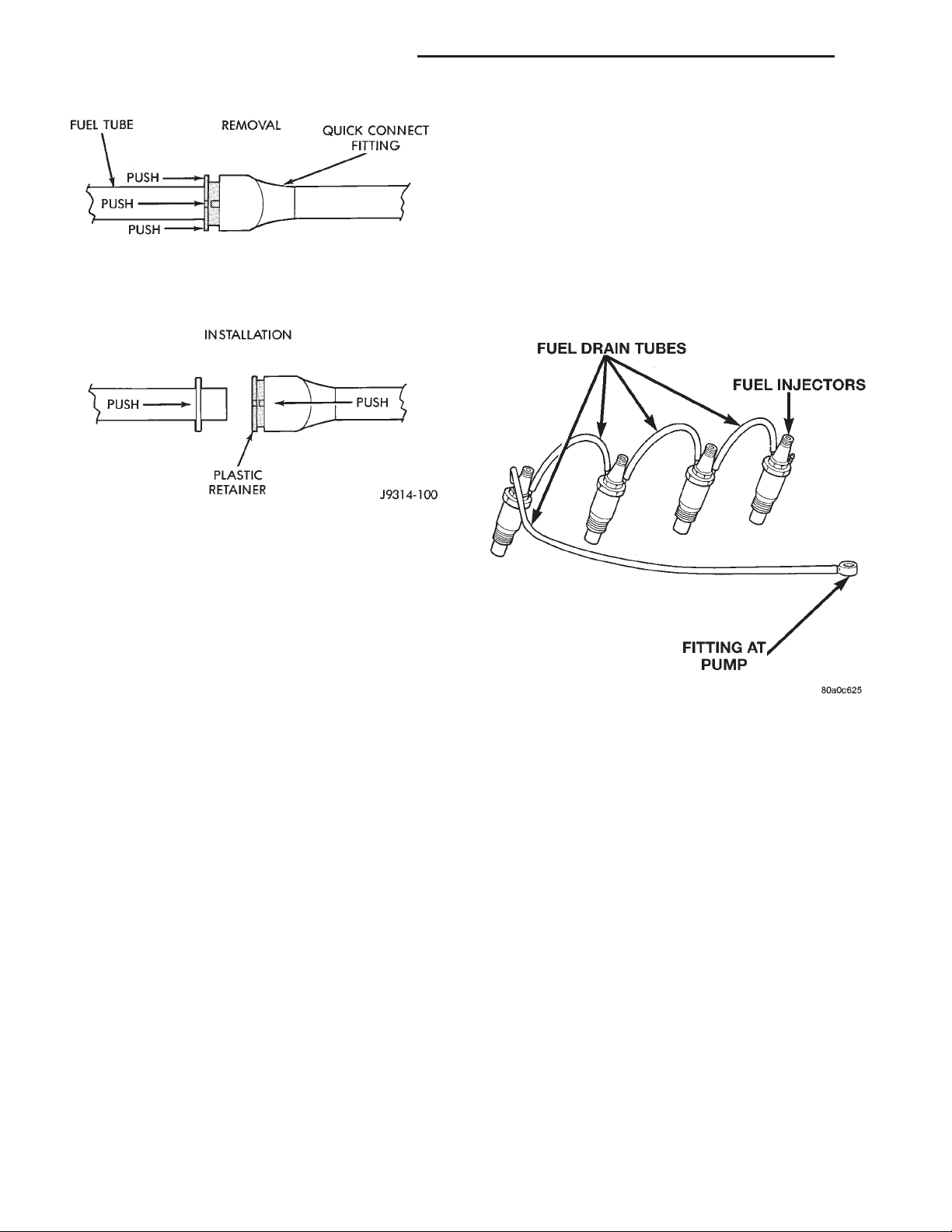
Fig. 6 Plastic Retainer Ring-Type Fitting
HIGH-PRESSURE FUEL LINES
CAUTION: The high–pressure fuel lines must be
held securely in place in their holders. The lines
cannot contact each other or other components. Do
not attempt to weld high–pressure fuel lines or to
repair lines that are damaged. Only use the recommended lines when replacement of high–pressure
fuel line is necessary.
High–pressure fuel lines deliver fuel under pressure of up to approximately 45,000 kPa (6526 psi)
from the injection pump to the fuel injectors. The
lines expand and contract from the high–pressure
fuel pulses generated during the injection process. All
high–pressure fuel lines are of the same length and
inside diameter. Correct high–pressure fuel line
usage and installation is critical to smooth engine
operation.
WARNING: USE EXTREME CAUTION WHEN
INSPECTING FOR HIGH–PRESSURE FUEL LEAKS.
INSPECT FOR HIGH–PRESSURE FUEL LEAKS WITH
A SHEET OF CARDBOARD. HIGH FUEL INJECTION
PRESSURE CAN CAUSE PERSONAL INJURY IF
CONTACT IS MADE WITH THE SKIN.
FUEL DRAIN TUBES
These rubber tubes are low–pressure type.
Some excess fuel is continually vented from the
fuel injection pump. During injection, a small amount
of fuel flows past the injector nozzle and is not
Fig. 7 Fuel Drain Tubes
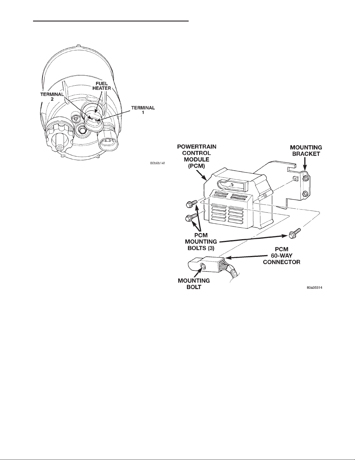
FUEL HEATER
The fuel heater is used to prevent diesel fuel from
waxing during cold weather operation. The fuel
heater is located in the bottom plastic bowl of the
fuel filter/water separator (Fig. 8).
The element inside the heater assembly is made of
a Positive Temperature Coefficient (PTC) material,
and has power applied to it by the fuel heater relay
anytime the ignition key is in the “on” position. PTC
material has a high resistance to current flow when
its temperature is high, which means that it will not
generate heat when the temperature is above a certain value. When the temperature is below 7°C (45°
F), the resistance of the PTC element is lowered, and
allows current to flow through the fuel heater element warming the fuel. When the temperature is
above 29°C (85° F), the PTC element’s resistance
rises, and current flow through the heater element
stops.
Voltage to operate the fuel heater is supplied from
the ignition (key) switch and through the fuel heater
relay. Refer to the following Fuel Heater Relay for
Page 7
XJ FUEL SYSTEM—2.5L DIESEL ENGINE 14 - 7
DESCRIPTION AND OPERATION (Continued)
VISUAL INSPECTION
A visual inspection for loose, disconnected, or incorrectly routed wires and hoses should be made before
attempting to diagnose or service the diesel fuel
injection system. A visual check will help find these
conditions. It also saves unnecessary test and diagnostic time. A thorough visual inspection of the fuel
injection system includes the following checks:
(1) Be sure that the battery connections are tight
and not corroded.
(2) Be sure that the 60 way connector is fully
engaged with the PCM (Fig. 9).
(3) Be sure that the 68 way connector is fully
engaged with the MSA (Fig. 10).
Fig. 8 Fuel Heater Temperature Sensor and Element
Location
additional information. The fuel heater and fuel
heater relay are not controlled by the Powertrain Control Module (ECM).
Current draw for the heater element is 150 watts
at 14 volts (DC).
FUEL HEATER RELAY
Voltage to operate the fuel heater is supplied from
the ignition (key) switch through the fuel heater
relay. The PCM or MSA is not used to control
this relay.
The fuel heater relay is located in the PDC. The
PDC is located next to the battery in the engine compartment. For the location of the relay within the
PDC, refer to label on PDC cover.
DIAGNOSIS AND TESTING
GENERAL INFORMATION
This section of the group will cover a general diagnosis of diesel engine fuel system components.
Diagnostic Trouble Codes: Refer to On-Board
Diagnostics in Group 25, Emission Control System
for a list of Diagnostic Trouble Codes (DTC’s) for certain fuel system components.
The PCM and MSA must be tested with the
DRBIII scan tool. The DRBIII should be the first
step in any diagnosis of engine performance complaints. Refer to the 1997 ZJ/ZG 2.5L Diesel Powertrain Diagnostic Procedures manual for diagnosis
and testing of the diesel engine control system.
Fig. 9 PCM Location—Typical
(4) Verify that the electrical connections for the
ASD relay are clean and free of corrosion. This relay
is located in the PDC. For the location of the relay
within the PDC, refer to label on PDC cover.
(5) Verify that the electrical connections for the
fuel heater relay are clean and free of corrosion. This
relay is located in the PDC. For the location of the
relay within the PDC, refer to label on PDC cover.
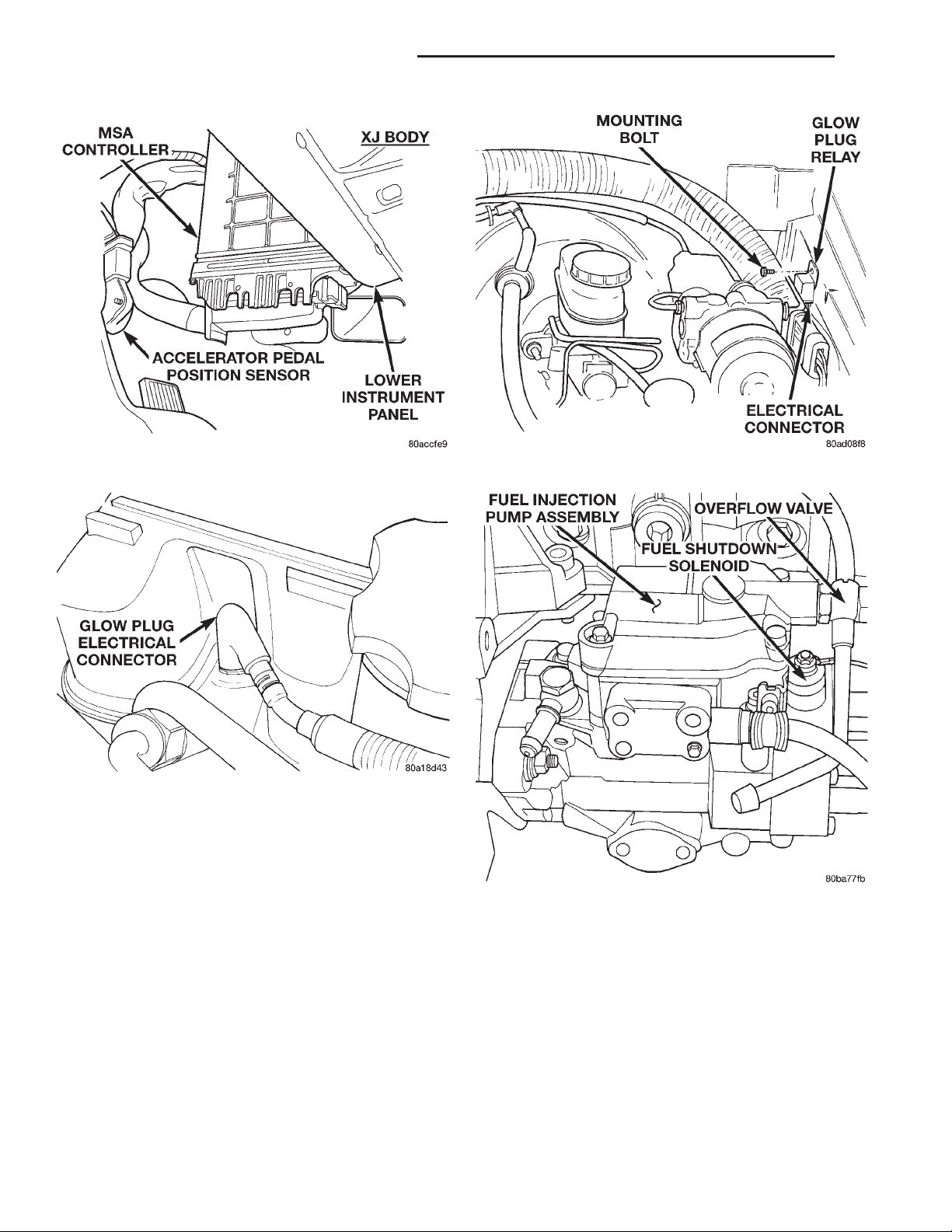
(6) Be sure the electrical connectors at the ends of
the glow plugs (Fig. 11) are tight and free of corrosion.
(7) Be sure that the electrical connections at the
glow plug relay are tight and not corroded. The glow
plug relay is located in the engine compartment on
the left–inner fender (Fig. 12).
(8) Inspect the starter motor and starter solenoid
connections for tightness and corrosion.
Page 8
14 - 8 FUEL SYSTEM—2.5L DIESEL ENGINE XJ
DIAGNOSIS AND TESTING (Continued)
Fig. 10 MSA Location—Typical
Fig. 11 Glow Plug Connector
(9) Verify that the Fuel Injection Pump electrical
connector is firmly connected. Inspect the connector
for corrosion or damaged wires. The solenoid is
mounted to the rear of the injection pump (Fig. 13).
(10) Verify that the fuel heater electrical connector
is firmly attached to the filter bowl at the bottom of
the fuel filter/water separator. Inspect the connector
for corrosion or damaged wires.
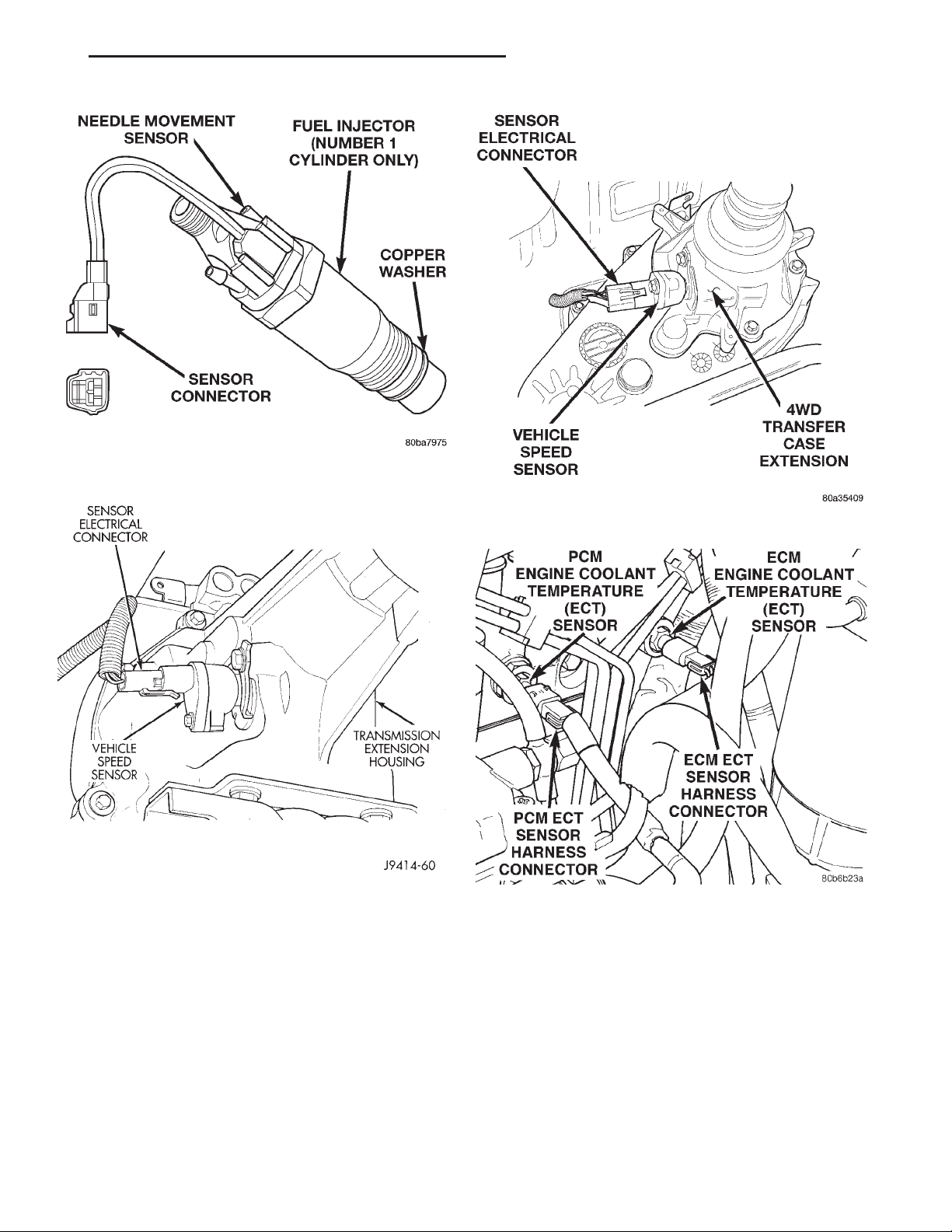
(11) Verify that the electrical pigtail connector
(sensor connector) (Fig. 14) for the fuel injector sensor is firmly connected to the engine wiring harness.
Inspect the connector for corrosion or damaged wires.
This sensor is used on the #1 cylinder injector only.
(12) Inspect for exhaust system restrictions such
as pinched exhaust pipes or a collapsed or plugged
muffler.
(13) Verify that the harness connector is firmly
connected to the vehicle speed sensor (Fig. 15) or
(Fig. 16).
Fig. 12 Glow Plug Relay Location
Fig. 13 Fuel Shutdown Solenoid Location
(14) Verify turbocharger wastegate operation.
Refer to Group 11, Exhaust System and Intake Manifold Group for information.
(15) Verify that the harness connector is firmly
connected to the engine coolant temperature sensor.
The sensor is located on the side of cylinder head
near the rear of fuel injection pump (Fig. 17).
(16) Check for air in the fuel system. Refer to the
Air Bleed Procedure.
(17) Inspect all fuel supply and return lines for
signs of leakage.
Page 9
XJ FUEL SYSTEM—2.5L DIESEL ENGINE 14 - 9
DIAGNOSIS AND TESTING (Continued)
Fig. 14 Fuel Injector Sensor
Fig. 15 Vehicle Speed Sensor—2 Wheel Drive
(18) Be sure that the ground connections are tight
and free of corrosion. Refer to Group 8, Wiring for
locations of ground connections.
(19) Inspect the air cleaner element (filter) for
restrictions.
(20) Be sure that the turbocharger output hose is
properly connected to the charge air cooler (intercooler) inlet tube. Verify that the charge air cooler
output hose is properly connected to the cooler and
the intake manifold. Refer to Group 11, Exhaust System and Intake Manifold for information.
(21) Be sure that the vacuum hoses to the vacuum
pump are connected and not leaking. The vacuum
Fig. 16 Vehicle Speed Sensor—4 Wheel Drive
Fig. 17 Engine Coolant Temperature Sensor
Location
pump is located in the front of engine (internal) and
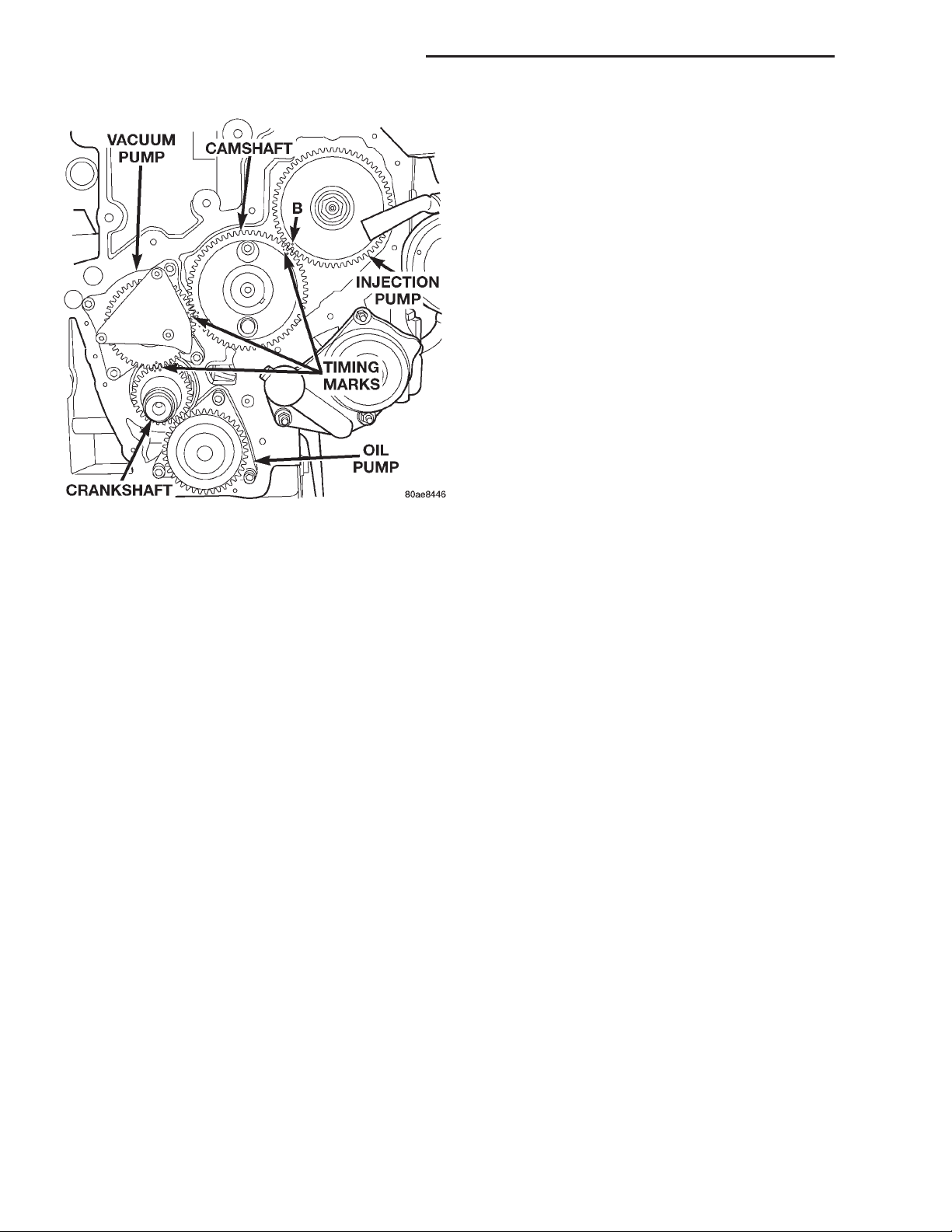
is driven from the crankshaft gear (Fig. 18). Disconnect the hose and check for minimum vacuum from
the pump. Refer to Group 5, Brake System for specifications and procedures.
(22) Be sure that the accessory drive belt is not
damaged or slipping.
(23) Verify there is a good connection at the engine
speed sensor. Refer to the Fuel Injection System in
this section for location of the engine speed sensor
location.
Page 10
14 - 10 FUEL SYSTEM—2.5L DIESEL ENGINE XJ
DIAGNOSIS AND TESTING (Continued)
FUEL INJECTOR TEST
The fuel injection nozzles, located on the engine
cylinder head, spray fuel under high pressure into
the individual combustion chambers. Pressurized
fuel, delivered by the fuel injection pump, unseats a
spring-loaded needle valve inside the injector, and
the fuel is atomized as it escapes through the injector
opening into the engine’s combustion chamber. If the
fuel injector does not operate properly, the engine
may misfire, or cause other driveability problems.
A leak in the injection pump–to–injector high–pressure fuel line can cause many of the same symptoms
as a malfunctioning injector. Inspect for a leak in the
high–pressure lines before checking for a malfunctioning fuel injector.
WARNING: THE INJECTION PUMP SUPPLIES
HIGH–PRESSURE FUEL OF UP TO APPROXIMATELY 45,000 KPA (6526 PSI) TO EACH INDIVIDUAL INJECTOR THROUGH THE HIGH–PRESSURE
LINES. FUEL UNDER THIS AMOUNT OF PRESSURE
CAN PENETRATE THE SKIN AND CAUSE PER-
Fig. 18 Vaccum Pump at Front of Engine
(24) Verify there is a good connection at the Boost
Pressure Sensor, which is a part of the air intake
assembly.
SONAL INJURY. WEAR SAFETY GOGGLES AND
ADEQUATE PROTECTIVE CLOTHING. AVOID CONTACT WITH FUEL SPRAY WHEN BLEEDING HIGH–
PRESSURE FUEL LINES.
AIR IN FUEL SYSTEM
Air will enter the fuel system whenever the fuel
supply lines, fuel filter/water separator, fuel filter
bowl, injection pump, high–pressure lines or injectors
are removed or disconnected. Air will also enter the
fuel system whenever the fuel tank has been run
empty.
Air trapped in the fuel system can result in hard
starting, a rough running engine, engine misfire, low
power, excessive smoke and fuel knock. After service
is performed, air must be bled from the system
before starting the engine.
Inspect the fuel system from the fuel tank to the
injectors for loose connections. Leaking fuel is an
indicator of loose connections or defective seals. Air
can also enter the fuel system between the fuel tank
and the injection pump. Inspect the fuel tank and
fuel lines for damage that might allow air into the
system.
For air bleeding, refer to Air Bleed Procedure in
the Service Procedures section of this group.
FUEL HEATER RELAY TEST
The fuel heater relay is located in the Power Distribution Center (PDC). Refer to Relays—Operation/
Testing in Fuel Injection System section of this group
for test procedures.
WARNING: DO NOT BLEED AIR FROM THE FUEL
SYSTEM OF A HOT ENGINE. DO NOT ALLOW FUEL
TO SPRAY ONTO THE EXHAUST MANIFOLD WHEN
BLEEDING AIR FROM THE FUEL SYSTEM.
To determine which fuel injector is malfunctioning,
run the engine and loosen the high–pressure fuel line
nut at the injector (Fig. 19). Listen for a change in
engine speed. If engine speed drops, the injector was
operating normally. If engine speed remains the
same, the injector may be malfunctioning. After testing, tighten the line nut to 30 N·m (22 ft. lbs.)
torque. Test all injectors in the same manner one at
a time.
Once an injector has been found to be malfunctioning, remove it from the engine and test it. Refer to
the Removal/Installation section of this group for procedures.
After the injector has been removed, install it to a
bench–mount injector tester. Refer to operating
instructions supplied with tester for procedures.
The opening pressure or “pop” pressure should be
15,000–15,800 kPa (2175–2291 psi). If the fuel injector needle valve is opening (“popping”) to early or to
late, replace the injector.
Page 11
XJ FUEL SYSTEM—2.5L DIESEL ENGINE 14 - 11
DIAGNOSIS AND TESTING (Continued)
A defective fuel injection pump, defective fuel timing solenoid or misadjusted mechanical pump timing
can cause starting problems or prevent the engine
from revving up. It can also cause:
• Engine surge at idle
• Rough idle (warm engine)
• Low power
• Excessive fuel consumption
• Poor performance
• Low power
• Black smoke from the exhaust
• Blue or white fog like exhaust
• Incorrect idle or maximum speed
The electronically controlled fuel pump has no
mechanical governor like older mechanically controlled fuel pumps. Do not remove the top cover of
Fig. 19 Typical Inspection of Fuel Injector
FUEL INJECTOR / NEEDLE MOVEMENT SENSOR TEST
The needle movement sensor is used only on the
number–1 cylinder fuel injector (Fig. 20). It is not
used on the injectors for cylinders number 2, 3, or 4.
the fuel pump, or the screws fastening the wiring
pigtail to the side of the pump. The warranty of
the injection pump and the engine may be void
if those seals have been removed or tampered
with.
FUEL SUPPLY RESTRICTIONS
Fig. 20 Needle Movement Sensor Location
Testing the needle movement sensor requires the
use of a DRB Scan tool. Refer to the Powertrain
Diagnostic Procedures manual for additional information.
LOW–PRESSURE LINES
Restricted or Plugged supply lines or fuel filter can
cause a timing fault that will cause the ECM to operate the engine in a “Limp Home” mode. See the
introduction of the Fuel Injection System in this
group for more information on the Limp Home mode.
Fuel supply line restrictions can cause starting problems and prevent the engine from revving up. The
starting problems include; low power and blue or
white fog like exhaust. Test all fuel supply lines for
restrictions or blockage. Flush or replace as necessary. Bleed the fuel system of air once a fuel supply
line has been replaced. Refer to the Air Bleed Procedure section of this group for procedures.
HIGH–PRESSURE LINES
Restricted (kinked or bent) high–pressure lines can
cause starting problems, poor engine performance
and black smoke from exhaust.
Examine all high–pressure lines for any damage.
Each radius on each high–pressure line must be
smooth and free of any bends or kinks.
Replace damaged, restricted or leaking high–pressure fuel lines with the correct replacement line.
FUEL INJECTION PUMP TEST
The injection pump is not to be serviced or
the warranty may be voided. If the injection
pump requires service, the complete assembly
must be replaced.
Incorrect injection pump timing (mechanical or
electrical) can cause poor performance, excessive
smoke and emissions and poor fuel economy.
CAUTION: The high–pressure fuel lines must be
clamped securely in place in the holders. The lines
cannot contact each other or other components. Do
not attempt to weld high–pressure fuel lines or to
repair lines that are damaged. Only use the recommended lines when replacement of high–pressure
fuel line is necessary.
Page 12
14 - 12 FUEL SYSTEM—2.5L DIESEL ENGINE XJ
DIAGNOSIS AND TESTING (Continued)
FUEL SHUTDOWN SOLENOID TEST
Refer to 1997 ZJ/ZG 2.5L Diesel Powertrain Diagnostic Manual for the Fuel Shutdown Solenoid test.
HIGH-PRESSURE FUEL LINE LEAK TEST
High–pressure fuel line leaks can cause starting
problems and poor engine performance.
WARNING: DUE TO EXTREME FUEL PRESSURES OF
UP TO 45,000 KPA (6526 PSI), USE EXTREME CAUTION WHEN INSPECTING FOR HIGH–PRESSURE FUEL
LEAKS. DO NOT GET YOUR HAND, OR ANY PART OF
YOUR BODY NEAR A SUSPECTED LEAK. INSPECT
FOR HIGH–PRESSURE FUEL LEAKS WITH A SHEET
OF CARDBOARD. HIGH FUEL INJECTION PRESSURE
CAN CAUSE PERSONAL INJURY IF CONTACT IS
MADE WITH THE SKIN.
Start the engine. Move the cardboard over the
high–pressure fuel lines and check for fuel spray onto
the cardboard (Fig. 21). If a high–pressure line connection is leaking, bleed the system and tighten the
connection. Refer to the Air Bleed Procedure in this
group for procedures. Replace damaged, restricted or
leaking high–pressure fuel lines with the correct
replacement line.
SERVICE PROCEDURES
AIR BLEED PROCEDURES
AIR BLEEDING AT FUEL FILTER
A certain amount of air may become trapped in the
fuel system when fuel system components are serviced or replaced. Bleed the system as needed after
fuel system service according to the following procedures.
WARNING: DO NOT BLEED AIR FROM THE FUEL
SYSTEM OF A HOT ENGINE. DO NOT ALLOW FUEL
TO SPRAY ONTO THE EXHAUST MANIFOLD WHEN
BLEEDING AIR FROM THE FUEL SYSTEM.
Some air enters the fuel system when the fuel filter or injection pump supply line is changed. This
small amount of air is vented automatically from the
injection pump through the fuel drain manifold tubes
if the filter was changed according to instructions.
Ensure the bowl of the fuel filter/water separator is
full of fuel.
It may be necessary to manually bleed the system
if:
• The bowl of the fuel filter/water separator is not
partially filled before installation of a new filter
• The injection pump is replaced
• High–pressure fuel line connections are loosened
or lines replaced
• Initial engine start–up or start–up after an
extended period of no engine operation
• Running fuel tank empty
Fig. 21 Typical Fuel Pressure Test at Injector
CAUTION: The high–pressure fuel lines must be
clamped securely in place in the holders. The lines
cannot contact each other or other components. Do
not attempt to weld high–pressure fuel lines or to
repair lines that are damaged. Only use the recommended lines when replacement of high–pressure
fuel line is necessary.
FUEL INJECTION PUMP BLEEDING
(1) If the fuel injection pump has been replaced,
air should be bled at the overflow valve before
attempting to start engine.
(a) Loosen the overflow valve (Fig. 22) at the
rear of the injection pump.
(b) Place a towel below the valve.
WARNING: WHEN CRANKING THE ENGINE TO
BLEED AIR FROM THE INJECTION PUMP, THE
ENGINE MAY START. PLACE THE TRANSMISSION
IN NEUTRAL OR PARK AND SET PARKING BRAKE
BEFORE ENGAGING THE STARTER MOTOR.
CAUTION: Do not engage the starter motor for
more than 30 seconds at a time. Allow 2 minutes
between cranking intervals.
Page 13
XJ FUEL SYSTEM—2.5L DIESEL ENGINE 14 - 13
SERVICE PROCEDURES (Continued)
Fig. 23 Bleeding High–Pressure Fuel Line—Typical
FUEL INJECTION PUMP TIMING
Fig. 22 Overflow Valve
(2) Crank the engine for 30 seconds at a time to
allow air trapped in the injection pump to vent out
the fuel injector drain tubes. Continue this procedure
until the engine starts. Observe the previous WARNING and CAUTION.
(3) Tighten overflow valve.
HIGH–PRESSURE FUEL LINE BLEEDING
WARNING: THE INJECTION PUMP SUPPLIES HIGH–PRESSURE FUEL OF APPROXIMATELY 59,000 KPA
(8,557 PSI) TO EACH INDIVIDUAL INJECTOR
THROUGH THE HIGH–PRESSURE LINES. FUEL
UNDER THIS AMOUNT OF PRESSURE CAN PENETRATE THE SKIN AND CAUSE PERSONAL INJURY.
WEAR SAFETY GOGGLES AND ADEQUATE PROTECTIVE CLOTHING AND AVOID CONTACT WITH
FUEL SPRAY WHEN BLEEDING HIGH–PRESSURE
FUEL LINES.
Refer to Removal/Installation and Adjusting Fuel
Pump Timing in this Group.
REMOVAL AND INSTALLATION
ACCELERATOR PEDAL
REMOVAL
(1) Disconnect electrical connector.
(2) Remove accelerator pedal mounting bracket
nuts. Remove accelerator pedal assembly.
INSTALLATION
(1) Place accelerator pedal assembly over studs
protruding from floor pan. Tighten mounting nuts to
5 N·m (46 in. lbs.) torque.
(2) Connect electrical connector.
(3) Before starting the engine, operate the accelerator pedal to check for any binding.
AIR CLEANER ELEMENT
WARNING: DO NOT BLEED AIR FROM THE FUEL
SYSTEM OF A HOT ENGINE. DO NOT ALLOW FUEL
TO SPRAY ONTO THE EXHAUST MANIFOLD WHEN
BLEEDING AIR FROM THE FUEL SYSTEM.
Bleed air from one injector at time.
(1) Loosen the high–pressure fuel line fitting at
the injector (Fig. 23).
(2) Crank the engine until all air has been bled
from the line. Do not operate the starter motor
for longer than 30 seconds. Wait 2 minutes
between cranking intervals.
(3) Start the engine and bleed one injector at a
time until the engine runs smoothly.
REMOVAL
(1) Remove hose clamp at Mass Air Flow Sensor.
(2) Remove hose from Mass Air Flow Sensor.
(3) Loosen 2 clamps holding air cleaner housing
halves together.
(4) Remove left side of air cleaner housing.
(5) Remove element from air cleaner housing.
INSTALLATION
(1) Install a new element in housing.
(2) Position left side of housing.
(3) Snap clamps into place.
(4) Install hoses and clamps.
Page 14
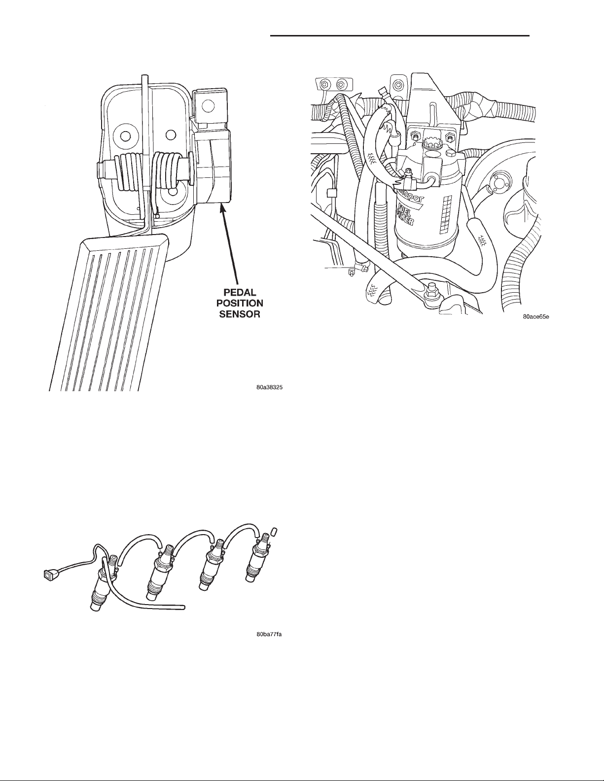
14 - 14 FUEL SYSTEM—2.5L DIESEL ENGINE XJ
REMOVAL AND INSTALLATION (Continued)
Fig. 24 Accelerator Pedal Mounting-Typical
FUEL DRAIN TUBES
The fuel drain tubes (Fig. 25) are low–pressure
type.
Pull each tube from the injector for removal. Push
on for installation. Clamps are not required for these
tubes.
Fig. 25 Fuel Injectors and Drain Tubes
FUEL FILTER/WATER SEPARATOR
The fuel filter/water separator is located in the
engine compartment on the left side near the shock
tower. (Fig. 26).
Fig. 26 Fuel Filter/Water Separator Location
The fuel filter/water separator assembly contains
the fuel filter, fuel heater element, and fuel drain
valve (Fig. 26).
DRAINING WATER FROM FILTER BOWL
Moisture (water) collects at the bottom of the filter/
separator in a plastic bowl. Water entering the fuel
injection pump can cause serious damage to the
pump. Note that the bulb will be illuminated for
approximately 2 seconds each time the key is
initially placed in the ON position. This is done
for a bulb check.
WARNING: DO NOT ATTEMPT TO DRAIN WATER
FROM THE FILTER/SEPARATOR WITH THE ENGINE
HOT.
(1) The bottom of the filter/separator bowl is
equipped with a drain valve (Fig. 26). The drain
valve is equipped with a fitting. Attach a piece of
rubber hose to this fitting. This hose is to be used as
a drain hose.
(2) Place a drain pan under the drain hose.
(3) With the engine not running, open the drain
valve (unscrew—drain valve has right hand threads)
from the filter/separator bowl. To gain access to this
fitting, the two filter–to–mounting bracket nuts (Fig.
26) may have to be loosened a few turns.
(4) Hold the drain open until clean fuel exits the
drain.
(5) After draining, close drain valve.
(6) Remove rubber drain hose.
(7) Dispose of mixture in drain pan according to
applicable local or federal regulations.
Page 15
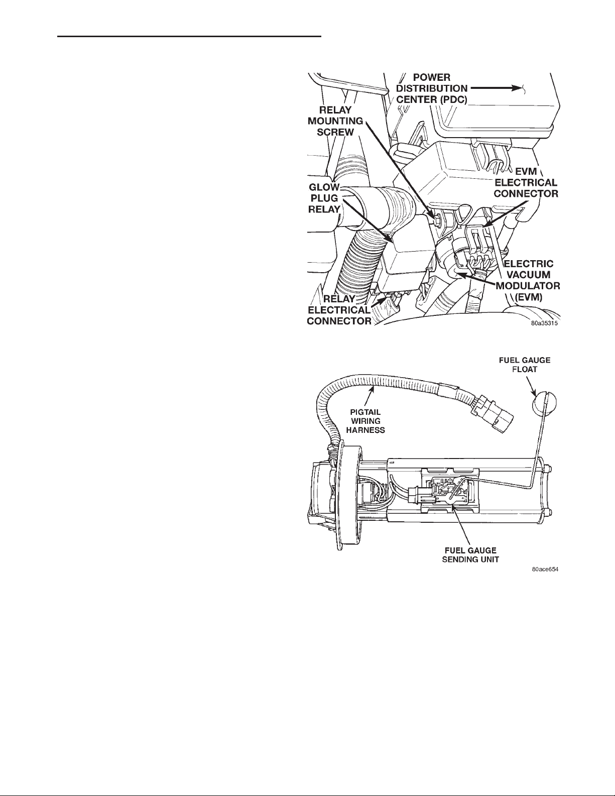
XJ FUEL SYSTEM—2.5L DIESEL ENGINE 14 - 15
REMOVAL AND INSTALLATION (Continued)
FUEL FILTER REMOVAL
(1) Drain all fuel and/or water from fuel filter/water separator assembly. Refer to the previous Draining Water From Filter Bowl.
(2) Unplug the electrical connectors at bottom of
plastic bowl.
(3) Remove plastic bowl from bottom of fuel filter
(unscrews).
(4) Remove fuel filter from bottom of filter base
(unscrews).
FUEL FILTER INSTALLATION
(1) Clean bottom of fuel filter base.
(2) Apply clean diesel fuel to new fuel filter gasket.
(3) Install and tighten filter to filter base. The beveled part of the rubber gasket should be facing up
towards the filter base.
(4) Clean the inside of bowl with a soap and water
mixture before installation. Carefully clean any residue between the two metal probes at the top of the
water–in–fuel sensor. Do not use chemical cleaners
as damage to the plastic bowl may result.
(5) Pour diesel fuel into the plastic bowl before
installing bowl to bottom of fuel filter. Do this to help
prevent air from entering fuel injection pump while
attempting to starting engine.
(6) Install filter bowl to bottom of filter.
(7) Install the electrical connectors at bottom of
bowl.
(8) Tighten the filter–to–mounting bracket nuts
(Fig. 26) to 28 N·m (250 in. lbs.) torque.
Fig. 27 Power Distribution Center (PDC) Location
FUEL HEATER
If the fuel heater element needs replacement, the
plastic filter bowl assembly must be replaced. Refer
to Fuel Filter/Water Separator for information.
FUEL HEATER RELAY
The fuel heater relay is located in the PDC. For
the location of the relay within the PDC (Fig. 27),
refer to label on PDC cover.
FUEL LEVEL SENSOR
The fuel level sensor is located on the side of the
fuel pump module (Fig. 28).
REMOVAL
(1) Remove fuel tank. Refer to Fuel Tank Removal/
Installation.
(2) Remove fuel pump module. Refer to Fuel Pump
Module Removal/Installation.
(3) Remove electrical wire connector at sending
unit terminals.
(4) Press on release tab (Fig. 29) to remove sending unit from pump module.
Fig. 28 Fuel Level Sensor
FUEL INJECTION PUMP
REMOVAL
(1) Disconnect the negative battery cable.
(2) Thoroughly clean the area around the injection
pump and fuel lines of all dirt, grease and other contaminants. Due to the close internal tolerances
of the injection pump, this step must be performed before removing pump.
Page 16
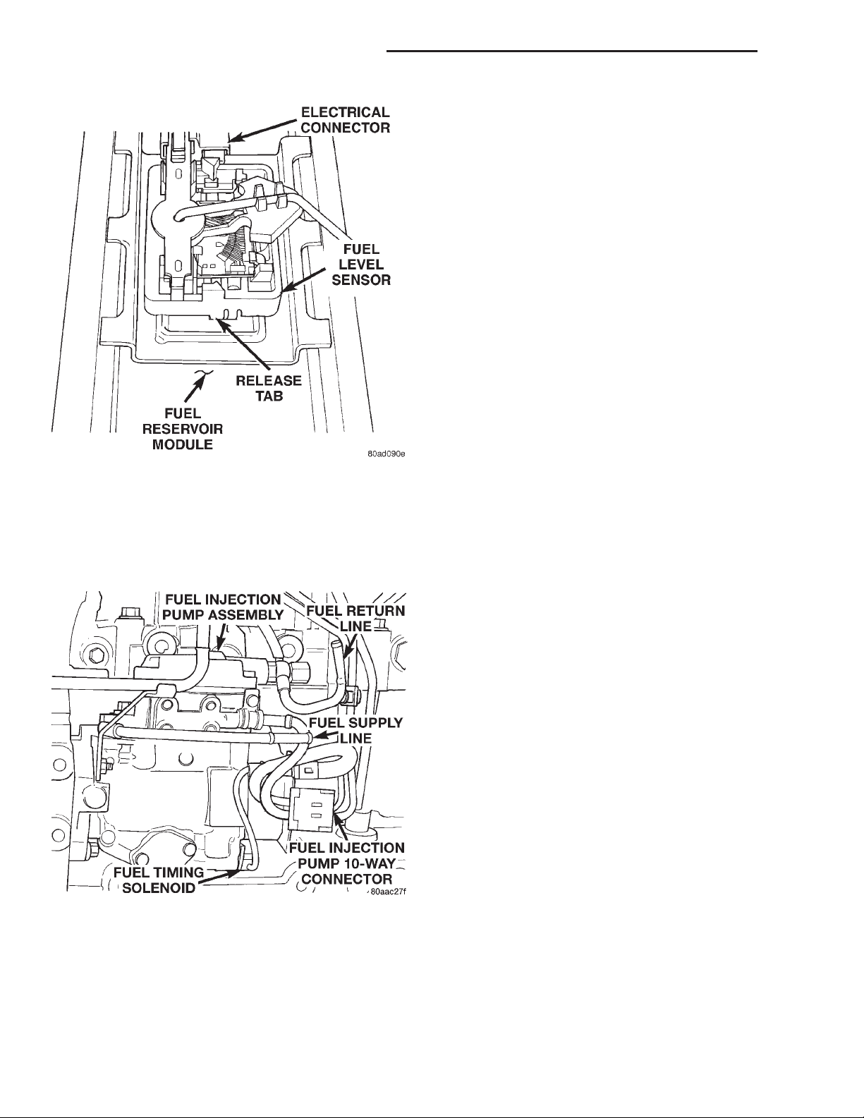
14 - 16 FUEL SYSTEM—2.5L DIESEL ENGINE XJ
REMOVAL AND INSTALLATION (Continued)
(9) Disconnect the four high–pressure fuel lines
from the fuel injection pump. Also disconnect fuel
lines at the fuel injectors. For procedures, refer to
High–Pressure Fuel Lines in this group. Place a rag
beneath the fittings to catch excess fuel.
(10) Remove the plug from timing gear cover.
(11) The “Top Dead Center” (TDC) compression firing stroke for the #1 cylinder can be determined as
follows:
(a) Using a socket attached to the front of the
crankshaft, rotate the engine clockwise until special alignment tool VM# 1035 can be inserted
through the hole in the bottom of the clutch housing, stopping the flywheel rotation. This position is
TDC or 180° away from TDC. Engine must be at
TDC #1 compression firing stroke.
(b) To verify that you are at TDC. Remove the
oil fill cap from the cylinder head cover and the
alignment tool from the clutch housing.
(c) Rotate the crankshaft one-quarter turn clockwise and counter-clockwise while observing the
rocker arm through the oil fill cap hole. If the
Fig. 29 Fuel Level Sensor Release Tab
(3) Remove the engine accessory drive belt. Refer
to Group 7, Cooling System for procedures.
(4) Remove the generator assembly.
(5) Remove the rubber fuel return and supply
hoses from the metal lines at the pump (Fig. 30).
Fig. 30 Fuel Injection Pump
(6) Remove the electrical connector at engine cool-
ant temperature sensor.
(7) Disconnect the Fuel Injection Pump electrical
connector at fuel pump (Fig. 30).
(8) Disconnect the main engine wiring harness
from the glow plugs.
rocker arm moves you are not at TDC.
(d) If TDC was found continue, if not rotate the
crankshaft one revolution until the alignment tool
can be re-installed in the flywheel. You are now at
TDC for the #1 cylinder compression firing stroke.
Mark the damper and timing cover for reference to
TDC. Remove the alignment tool from the clutch
housing.
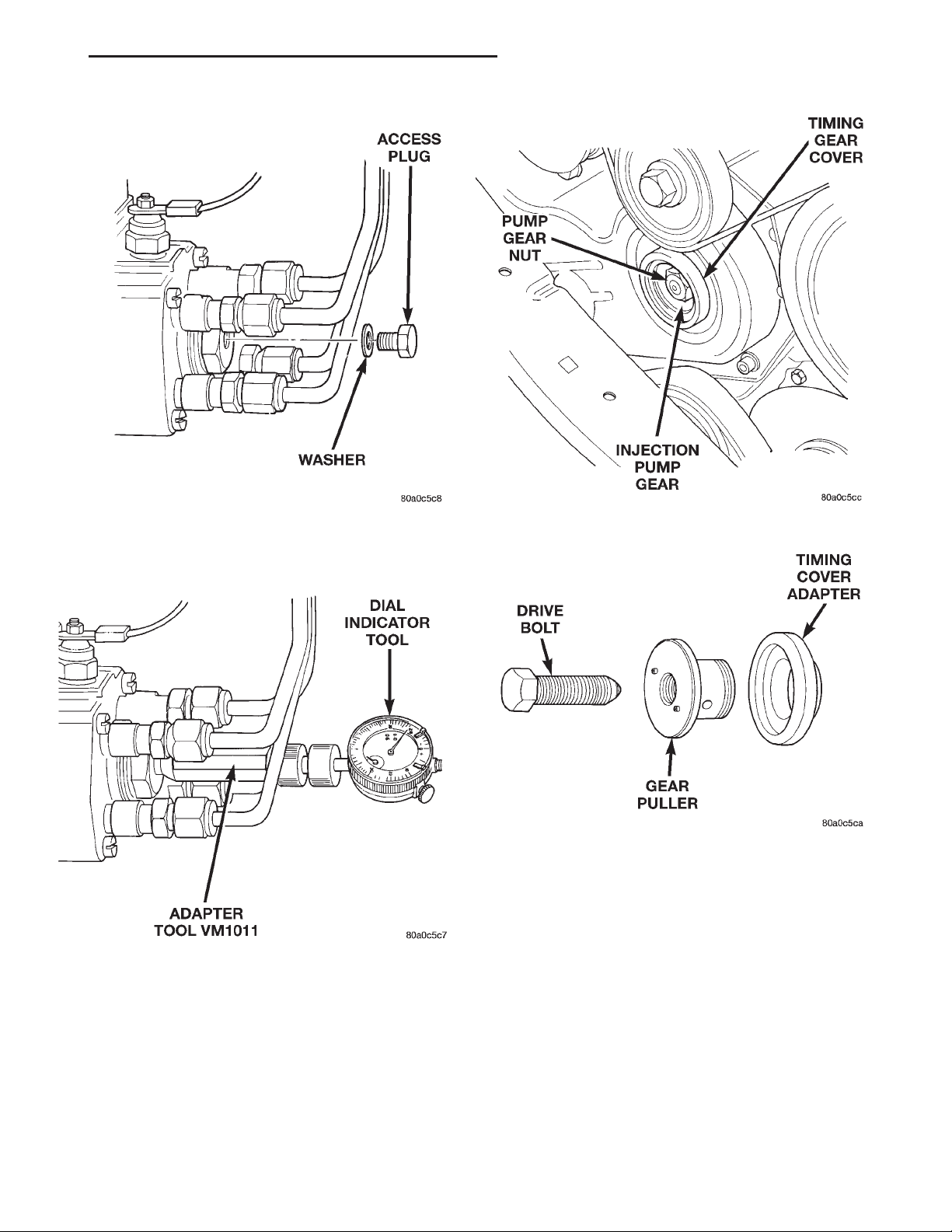
(12) Remove access plug and plug washer at rear
of pump (Fig. 31). Thread special dial indicator and
adapter tool VM.1011 (Fig. 32) into this opening.
Hand tighten only.
(13) Slightly rotate the engine in a counter-clock-
wise direction until the dial gauge indicator stops
moving (20°-25° before TDC).
(14) Remove injection pump drive gear nut (Fig.
33).
(15) A special 3–piece gear removal tool set
VM.1003 (Fig. 34) must be used to remove the injection pump drive gear from the pump shaft.
(a) Thread the adapter (Fig. 35) into the timing
cover.
(b) Thread the gear puller into the injection
pump drive gear (Fig. 35). This tool is also used to
hold the gear in synchronization during pump
removal.
(c) Remove the three injection pump–to–gear
cover mounting nuts (Fig. 36). CAUTION: This
step must be done to prevent injection pump
damage.
(d) Install the drive bolt into the gear puller
(Fig. 35). Tighten the drive bolt to press (remove)
the drive gear from injection pump shaft while
Page 17
XJ FUEL SYSTEM—2.5L DIESEL ENGINE 14 - 17
REMOVAL AND INSTALLATION (Continued)
Fig. 31 Access Plug at Rear of Pump
Fig. 32 Installing Dial Indicator and Special Adapter
Tools
driving injection pump rearward from timing gear
cover mounting studs.
(16) Remove pump from engine. Do not rotate
engine while gear puller is installed. Engine
damage will occur.
INSTALLATION/ADJUSTING PUMP TIMING
(1) Clean the mating surfaces of injection pump
and timing gear cover.
Fig. 33 Removing Pump Drive Gear Nut
Fig. 34 Pump Gear Tools
(2) Install a new injection pump–to–timing gear
cover gasket.
(3) Remove the gear removing bolt (drive bolt)
from gear puller. CAUTION: Do not remove the
special gear puller or timing cover adapter
tools from timing cover at this time. Gear misalignment will result.
(4) Place the key way on the pump shaft to the 11
o’clock position as viewed from the front of pump.
Install the pump into the rear of timing gear cover
while aligning key way on pump shaft into pump
gear.
(5) Install and snug the 3 injection pump mount-
ing nuts. This is not the final tightening sequence.
(6) Remove the special gear puller and adapter
tools from timing gear cover.
Page 18
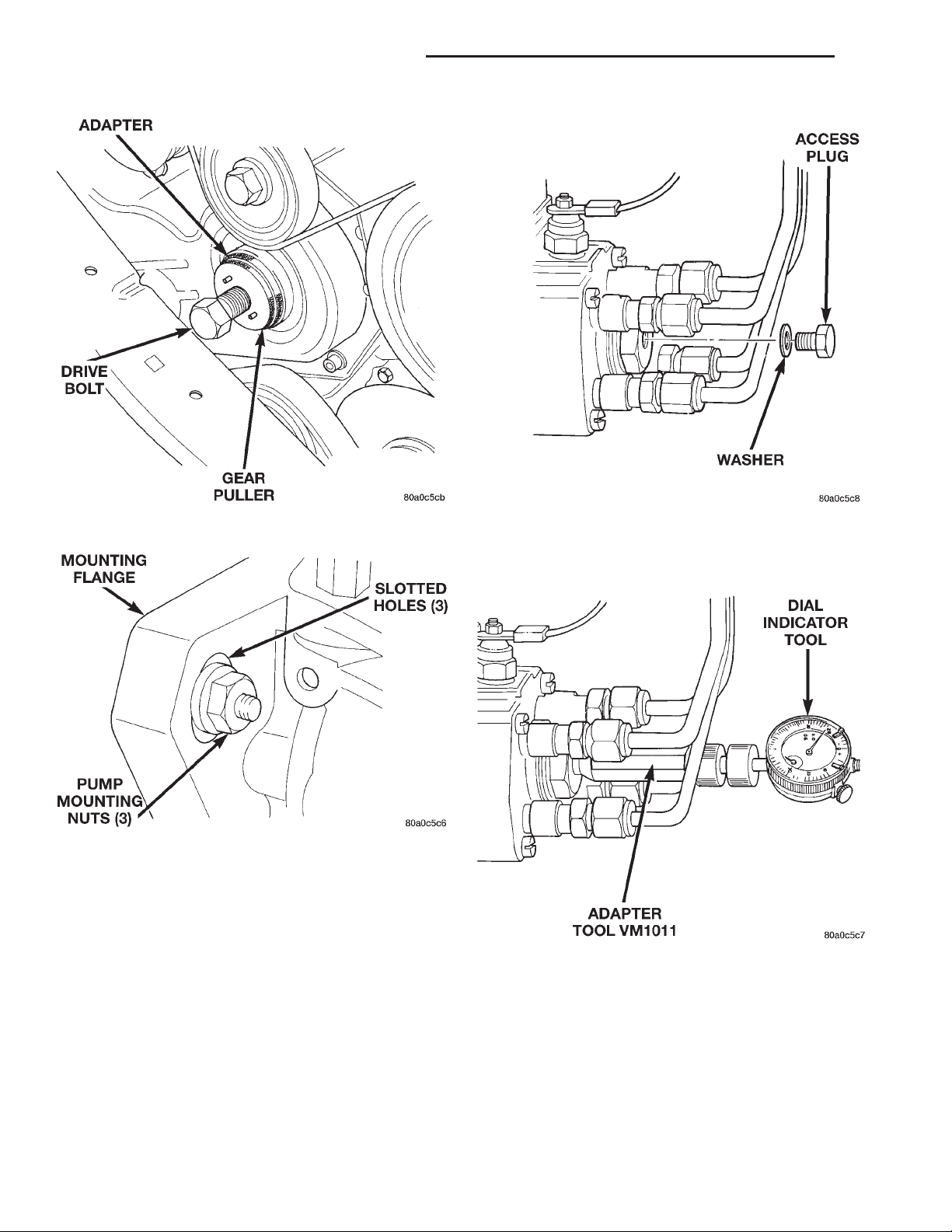
14 - 18 FUEL SYSTEM—2.5L DIESEL ENGINE XJ
REMOVAL AND INSTALLATION (Continued)
Fig. 35 Installing Pump Drive Gear Removal Tools
Fig. 36 Injection Pump Mounting Nuts
(7) Install the injection pump drive gear nut.
Tighten nut to 88 N·m (65 ft. lbs.) torque.
(8) Remove the access plug and plug washer at
rear of pump (Fig. 37). Thread special dial indicator
adapter tool VM.1011 (Fig. 38) into this opening.
Hand tighten only.
(9) Attach special dial indicator tool VM.1013 into
the adapter tool (Fig. 38).
(10) Using a socket attached to the front of the
crankshaft, rotate the engine in a counter-clockwise
direction until the dial gage indicator stops moving
(20–25° before TDC).
(11) Set the dial indicator to 0mm. Be sure the tip
of the dial indicator is touching the tip inside the
adapter tool.
Fig. 37 Access Plug at Rear of Pump
Fig. 38 Installing Dial Indicator and Special Adapter
Tools
(12) The “Top Dead Center” (TDC) compression fir-
ing stroke can be determined as follows:
(a) Rotate the engine clockwise until special
alignment tool VM# 1035 can be inserted through
the hole in the bottom of the clutch housing, stopping the flywheel rotation. This position is TDC or
180° away from TDC. Engine must be at TDC #1
compression firing stroke.
Page 19
XJ FUEL SYSTEM—2.5L DIESEL ENGINE 14 - 19
REMOVAL AND INSTALLATION (Continued)
(b) To verify that you are at TDC. Remove the
oil fill cap from the rocker cover and the alignment
tool from the clutch housing.
(c) Rotate the crankshaft one-quarter turn clockwise and counter-clockwise while observing the
rocker arm through the oil fill cap hole. If the
rocker arm moves you are not at TDC.
(d) If TDC was found continue, if not rotate the
crankshaft one revolution until the alignment tool
can be re-installed in the flywheel. You are now at
TDC.
(13) The gauge reading should be at 0.60 mm. If
not, the pump must be rotated for adjustment:
(a) Loosen the three injection pump mounting
nuts at the mounting flanges. These flanges are
equipped with slotted holes. The slotted holes are
used to rotate and position the injection pump for
fuel timing. Loosen the three nuts just enough to
rotate the pump.
(b) Rotate the pump until 0.60 mm is indicated
on the dial indicator gauge. If while rotating the
pump the 0.60mm specification is passed do not
attempt to rotate the pump in the opposite direction. You must rotate the pump back below the
0.60mm specification and start the procedure over
from the start of the TDC procedure. This will prevent a false reading due to gear backlash.
(c) Tighten the three pump mounting nuts to 30
N·m (22 ft. lbs.) torque.
(d) Recheck the dial indicator after tightening
the pump mounting nuts. Gauge should still be
reading 0.60 mm.
(14) Remove dial indicator and adapter tools.
(15) Install access plug and washer to rear of
injection pump.
(16) Install plug at timing gear cover.
(17) Install and connect the four high–pressure
fuel lines to the fuel injection pump. Also connect
fuel lines at the fuel injectors. For procedures, refer
to High–Pressure Fuel Lines in this group.
(18) Install electrical connector at engine coolant
temperature sensor.
(19) Connect electrical connector at fuel shutdown
solenoid.
(20) Connect the main engine wiring harness to
the glow plugs.
(21) Connect the fuel timing solenoid pigtail har-
ness to the engine wiring harness.
(22) Connect the overflow valve/banjo fitting (fuel
return line assembly). Replace copper gaskets before
installing.
(23) Connect the rubber fuel return and supply
hoses to metal lines at pump. Tighten hose clamps to
2 N·m (20 in. lbs.) torque.
(24) Install generator assembly.
(25) Install engine accessory drive belt. Refer to
Group 7, Cooling System for procedures.
(26) Install negative battery cable to battery.
(27) Start the engine and bring to normal operat-
ing temperature.
(28) Check for fuel leaks.
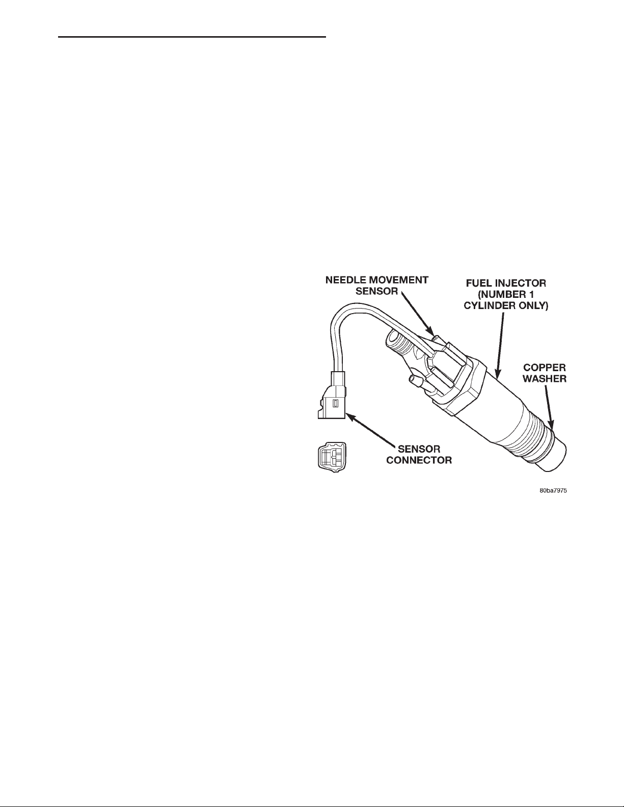
FUEL INJECTORS
Four fuel injectors are used on each engine. Of
these four, two different types are used. The fuel
injector used on cylinder number one is equipped
with a fuel injector sensor (Fig. 39). The other three
fuel injectors are identical. Do not place the fuel
injector equipped with the fuel injector sensor
into any other location except the cylinder
number one position.
Fig. 39 Fuel Injector Sensor — #1 Cylinder
REMOVAL
(1) Disconnect negative battery cable at battery.
(2) Thoroughly clean the area around the injector
with compressed air.
(3) Remove the fuel drain hoses (tubes) at each
injector (Fig. 40) being serviced. Each of these hoses
is slip–fit to the fitting on injector.
(4) Remove the high–pressure fuel line at injector
being removed. Refer to High–Pressure Fuel Lines in
this group for procedures.
(5) Remove the injector using special socket tool
number VM.1012A. When removing cylinder number
one injector, thread the wiring harness through the
access hole on the special socket (Fig. 41).
(6) Remove and discard the copper washer (seal) at
bottom of injector (Fig. 39).
Page 20
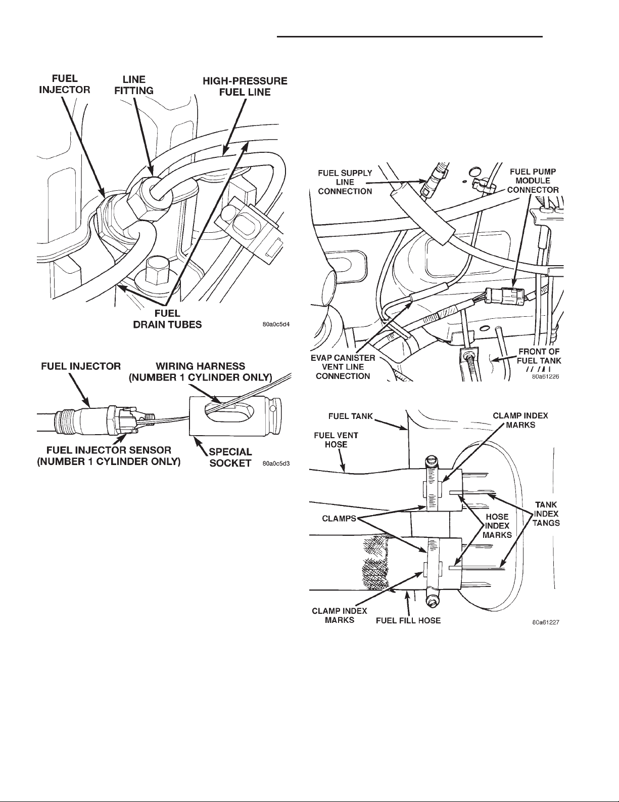
14 - 20 FUEL SYSTEM—2.5L DIESEL ENGINE XJ
REMOVAL AND INSTALLATION (Continued)
(3) Drain fuel tank dry into holding tank or a
properly labeled diesel safety container.
(4) Raise vehicle on hoist.
(5) Disconnect both the fuel fill and fuel vent rubber hoses at the fuel tank.
(6) Disconnect fuel supply and return lines from
the steel supply line (Fig. 42).
Fig. 40 Fuel Injector—Typical
Fig. 41 Wiring Harness Through Socket
INSTALLATION
(1) Clean the injector threads in cylinder head.
(2) Install new copper washer (seal) to injector.
(3) Install injector to engine. Tighten to 70 N·m
(52 ft. lbs.) torque.
(4) Install high–pressure fuel lines. Refer to High–
Pressure Fuel Lines in this group for procedures.
(5) Install fuel drain hoses (tubes) to each injector.
Do not use clamps at fuel drain hoses.
(6) Connect negative battery cable to battery.
(7) Bleed the air from the high–pressure lines.
Refer to the Air Bleed Procedure section of this
group.
FUEL TANK
REMOVAL
(1) Disconnect negative cable from battery.
(2) Insert fuel siphon hose into fuel filler neck and
push it into the tank.
Fig. 42 Fuel Tank Connections at Front of Tank
Fig. 43 Fuel Fill/Vent Hose Index Marks
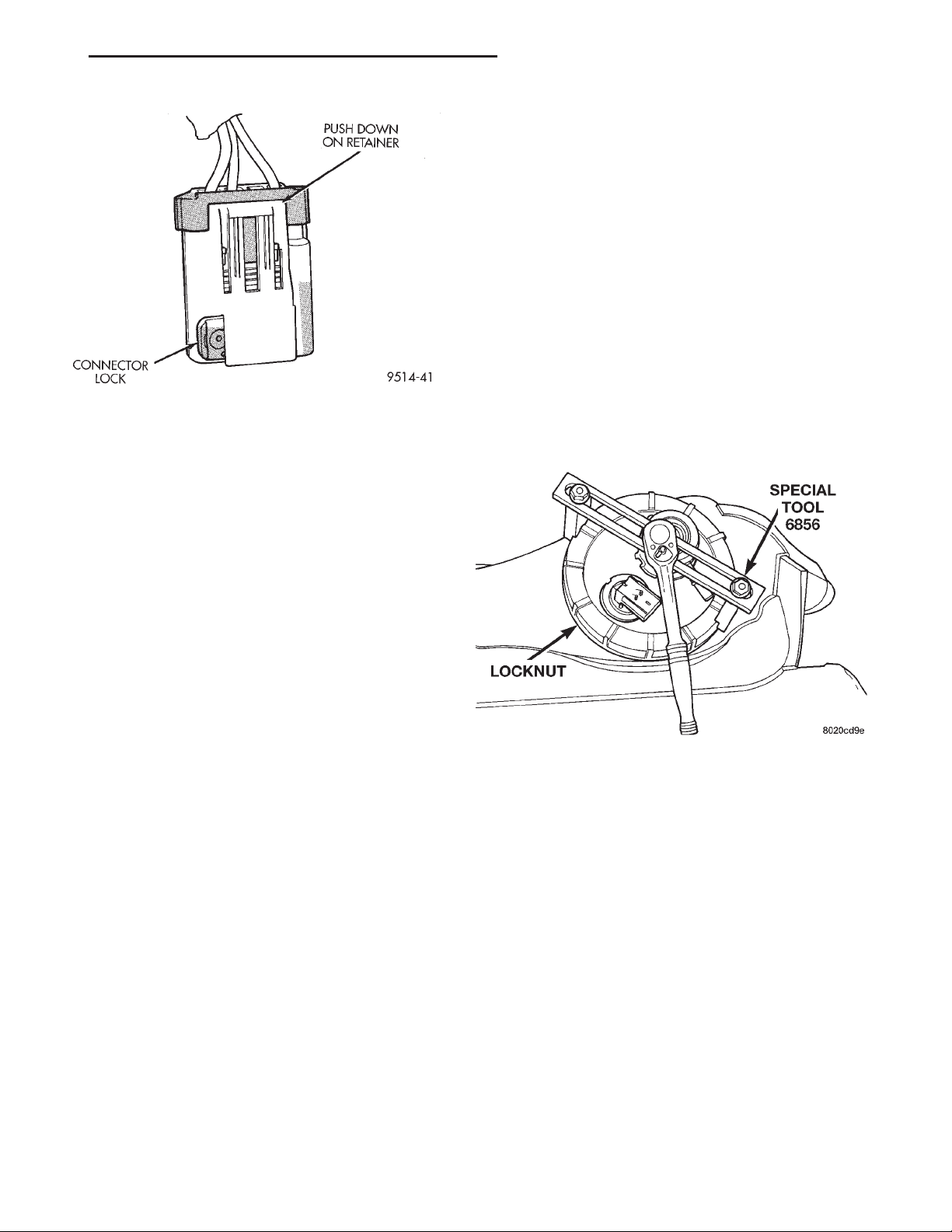
The fuel reservoir module electrical connec-
tor has a retainer that locks it in place.
(7) Slide electrical connector lock to unlock.
(8) Push down on connector retainer (Fig. 44) and
pull connector off module.
(9) Use a transmission jack to support fuel tank.
Remove bolts from fuel tank straps.
Page 21
XJ FUEL SYSTEM—2.5L DIESEL ENGINE 14 - 21
REMOVAL AND INSTALLATION (Continued)
(1) Disconnect negative cable from battery.
(2) Drain fuel tank dry into holding tank or a
properly labeled diesel safety container.
(3) Raise vehicle on hoist.
(4) Use a transmission jack to support the fuel
tank. Remove bolts from fuel tank straps. Lower
tank slightly.
(5) Clean area around fuel reservoir module and
tank to keep dirt and foreign material out of tank.
(6) Disconnect fuel lines from fuel module by
depressing quick connect retainers with thumb and
fore finger.
(7) Slide module electrical connector lock to
unlock.
(8) Push down on connector retainer and pull connector off module.
Fig. 44 Module Connector Retainer and Lock
(10) Lower tank slightly. Carefully remove filler
hose from tank.
(11) Lower the fuel tank. Remove clamp and
remove fuel filler tube vent hose. Remove fuel tank
from vehicle.
(9) Using Special Tool 6856, remove plastic locknut
counterclockwise to release pump module (Fig. 45).
INSTALLATION
(1) Position fuel tank on transmission jack. Connect fuel filler tube vent hose and replace clamp.
(2) Raise tank into position and carefully work
filler tube into tank. A light coating of clean engine
oil on the tube end may be used to aid assembly.
(3) Feed filler vent line thorough frame rail. Careful not to cross lines.
(4) Tighten strap bolts to 9 N·m (80 in. lbs.).
Remove transmission jack.
CAUTION: Ensure straps are not twisted or bent
before or after tightening strap nuts.
(5) Connect module electrical connector. Place
retainer in locked position.
(6) Lubricate the fuel supply and return lines with
clean 30 weight engine oil, install the quick connect
fuel fitting. Refer to Tube/Fitting Assembly in the
Fuel Delivery section of this Group.
(7) Attach filler line to filler tube. Pull on connector to make sure of connection.
(8) Fill fuel tank, replace cap, and connect battery
negative cable.
FUEL RESERVOIR MODULE
REMOVAL
WARNING: THE FUEL RESERVOIR OF THE FUEL
MODULE DOES NOT EMPTY OUT WHEN THE TANK
IS DRAINED. THE FUEL IN THE RESERVOIR WILL
SPILL OUT WHEN THE MODULE IS REMOVED.
Fig. 45 Fuel Reservoir Module Lock Nut Removal
(10) Carefully remove module and o-ring from
tank.
(11) Discard old o-ring.
INSTALLATION
(1) Thoroughly clean locknut threads and mating
fule tank threads. Use a soap/water solution. Do not
use carburetor cleaner to clean threads.
(2) Apply clean water to the o-ring seal and place
on the mating fuel tank threads.
(3) Wipe seal area of tank clean and place a new
o-ring seal in position on pump.
(4) Position fuel reservoir module in tank with
locknut.
(5) Tighten locknut to 75 N·m (55 ft. lbs.).
(6) Connect fuel lines.
(7) Plug in electrical connector. Slide connector
lock into position.
(8) Raise fuel tank, install bolts into fuel tank
straps and tighten.
(9) Lower vehicle on hoist.
Page 22
14 - 22 FUEL SYSTEM—2.5L DIESEL ENGINE XJ
REMOVAL AND INSTALLATION (Continued)
(10) Connect negative cable from battery.
(11) Fill fuel tank. Check for leaks.
(12) Install fuel filler cap.
HIGH-PRESSURE LINES
All high–pressure fuel lines are of the same length
and inside diameter. Correct high–pressure fuel line
usage and installation is critical to smooth engine
operation.
CAUTION: The high–pressure fuel lines must be
clamped securely in place in the holders. The lines
cannot contact each other or other components. Do
not attempt to weld high–pressure fuel lines or to
repair lines that are damaged. Only use the recommended lines when replacement of high–pressure
fuel line is necessary.
REMOVAL
(1) Disconnect negative battery cable from battery.
(2) Remove the necessary clamps holding the lines
to the engine.
(3) Clean the area around each fuel line connection. Disconnect each line at the top of each fuel
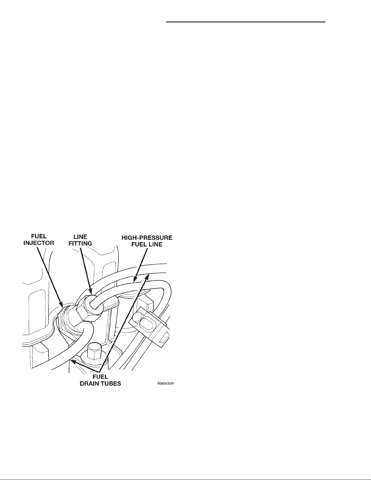
injector (Fig. 46).
(5) Very carefully remove each line from the
engine. Note the position (firing order) of each line
while removing. Do not bend the line while
removing.
CAUTION: Be sure that the high–pressure fuel lines
are installed in the same order that they were
removed. Prevent the injection pump delivery valve
holders from turning when removing or installing
high–pressure lines from injection pump.
INSTALLATION
(1) Carefully position each high–pressure fuel line
to the fuel injector and fuel injection pump delivery
valve holder in the correct firing order. Also position
each line in the correct line holder.
(2) Loosely install the line clamp/holder bolts.
(3) Tighten each line at the delivery valve to 30
N·m (22 ft. lbs.) torque.
(4) Tighten each line at the fuel injector to 30 N·m
(22 ft. lbs.) torque.
Be sure the lines are not contacting each
other or any other component.
(5) Tighten the clamp bracket bolts to 24 N·m (18
ft. lbs.) torque.
(6) Bleed air from the fuel system. Refer to the Air
Bleed Procedure section of this group.
Fig. 46 Fuel Lines at Fuel Injectors
(4) Disconnect each high–pressure line fitting at
each fuel injection pump delivery valve.
SPECIFICATIONS
FUEL TANK CAPACITY
75 Liters (20.0 Gals.)
Nominal refill capacities are shown. A variation
may be observed from vehicle to vehicle due to manufacturing tolerances, ambient temperatures and
refill procedures.
IDLE SPEED
900 rpm 625 rpm with engine at normal operating temperature.
FUEL INJECTOR FIRING SEQUENCE
1–3–4–2
FUEL SYSTEM PRESSURE
Peak Injection Pressure/Fuel Injection Pump
Operating Pressure: 40,000–45,000 kPa (5801–
6526 psi).
Opening Pressure of Fuel Injector:
15,000–15,800 kPa (2175–2291 psi).
Page 23

XJ FUEL SYSTEM—2.5L DIESEL ENGINE 14 - 23
FUEL INJECTION SYSTEM—2.5L DIESEL ENGINE
INDEX
page page
GENERAL INFORMATION
INTRODUCTION ......................... 23
DESCRIPTION AND OPERATION
AIR CONDITIONING (A/C) CONTROLS—
ECM INPUTS ......................... 27
AIR CONDITIONING RELAY—ECM OUTPUT . . . 28
ASD RELAY—ECM INPUT ................. 28
BATTERY VOLTAGE—PCM INPUT ........... 25
BOOST / PRESSURE SENSOR ............. 25
BRAKE SWITCH—ECM INPUT .............. 27
DATA LINK CONNECTOR—PCM AND ECM
INPUT AND OUTPUT ................... 27
ELECTRIC VACUUM MODULATOR (EVM)—
ECM OUTPUT ......................... 30
ENGINE COOLANT GAUGE—PCM OUTPUT . . . 28
ENGINE COOLANT TEMPERATURE SENSOR—
ECM/PCM INPUT ...................... 26
ENGINE OIL PRESSURE GAUGE—
PCM OUTPUT ......................... 28
ENGINE SPEED/CRANK POSITION SENSOR—
ECM INPUT ........................... 26
FIVE VOLT POWER—ECM/PCM OUTPUT ..... 28
FUEL INJECTOR SENSOR—GROUND........ 26
GLOW PLUG LAMP—PCM OUTPUT ......... 28
GLOW PLUG RELAY—ECM OUTPUT ........ 29
GLOW PLUGS .......................... 30
IGNITION CIRCUIT SENSE—MSA/PCM INPUT . 25
IGNITION CIRCUIT SENSE—PCM INPUT ..... 26
NEEDLE MOVEMENT OR INSTRUMENTED
FIRST INJECTOR—ECM INPUT ........... 26
POWER GROUND ....................... 26
POWERTRAIN CONTROL MODULE (PCM) .... 24
SENSOR RETURN—ECM/PCM INPUT
(ANALOG GROUND) .................... 25
SPEED CONTROL—ECM INPUT ............ 28
SPEED CONTROL—PCM OUTPUTS ......... 28
TACHOMETER—PCM OUTPUT ............. 29
TIMING SOLENOID—ECM OUTPUT .......... 29
VEHICLE SPEED SENSOR—ECM INPUT ..... 27
VEHICLE THEFT ALARM .................. 25
DIAGNOSIS AND TESTING
ASD RELAY TEST ....................... 30
BOOST / PRESSURE SENSOR ............. 33
DIAGNOSTIC TROUBLE CODES ............ 34
DIESEL DIAGNOSTICS ................... 30
ENGINE COOLANT TEMPERATURE
SENSOR TEST ........................ 30
ENGINE SPEED SENSOR TEST ............ 30
GLOW PLUG RELAY TEST ................ 32
GLOW PLUG TEST ...................... 31
RELAYS—OPERATION/TESTING ............ 32
VEHICLE SPEED SENSOR TEST ............ 34
REMOVAL AND INSTALLATION
A/C CLUTCH RELAY ..................... 34
ASD RELAY ............................ 34
ENGINE COOLANT TEMPERATURE SENSOR . . 34
ENGINE SPEED SENSOR ................. 34
GLOW PLUG RELAY ..................... 35
GLOW PLUGS .......................... 34
POWERTRAIN CONTROL MODULE (PCM) .... 35
VEHICLE SPEED SENSOR ................36
SPECIFICATIONS
GLOW PLUG CURRENT DRAW ............. 37
TORQUE CHART—2.5L DIESEL ............ 37
GENERAL INFORMATION
INTRODUCTION
This section will cover components either regulated
or controlled by the ECM controller and the Powertrain Control Module (PCM). The fuel heater relay
and fuel heater are not operated by the ECM controller or the PCM. These components are controlled by
the ignition (key) switch. All other fuel system electrical components necessary to operate the engine
are controlled or regulated by the ECM controller,
which interfaces with the PCM. Refer to the following description for more information.
Certain fuel system component failures may cause
a no start, or prevent the engine from running. It is
important to know that the ECM has a feature
where, if possible, it will ignore the failed sensor, set
a code related to the sensor, and operate the engine
in a “Limp Home” mode. When the ECM is operating
in a “Limp Home” mode, the Check Engine Lamp on
the instrument panel may be constantly illuminated,
and the engine will most likely have a noticeable loss
of performance. An example of this would be an
Accelerator Pedal Position Sensor failure, and in that
situation, the engine would run at a constant 1100
RPM, regardless of the actual position of the pedal.
This is the most extreme of the three “Limp Home”
modes.
When the Check Engine Lamp is illuminated constantly with the key on and the engine running, it
usually indicates a problem has been detected some-
Page 24
14 - 24 FUEL SYSTEM—2.5L DIESEL ENGINE XJ
GENERAL INFORMATION (Continued)
where within the fuel system. The DRBIII scan tool
is the best method for communicating with the ECM
and PCM to diagnose faults within the system.
DESCRIPTION AND OPERATION
POWERTRAIN CONTROL MODULE (PCM)
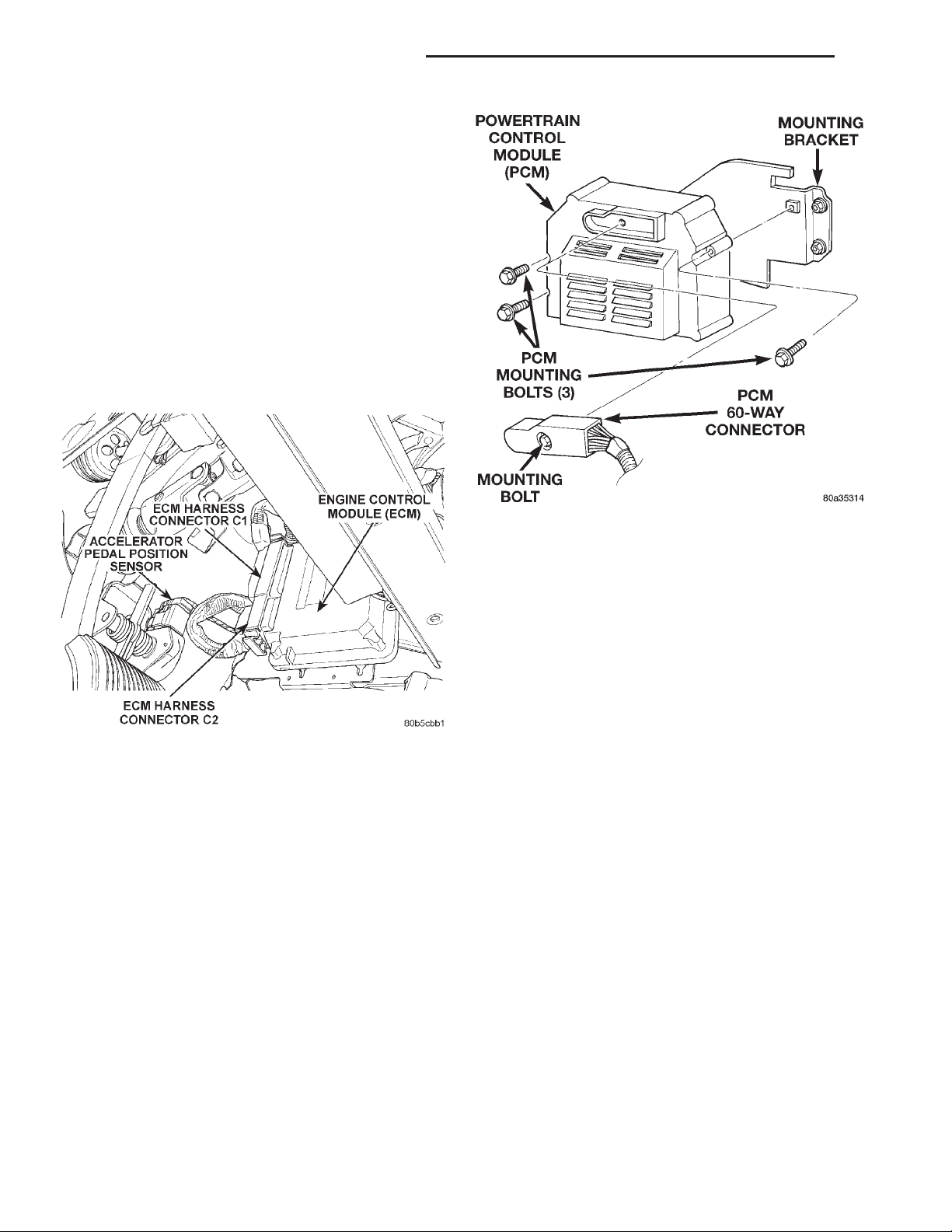
On LHD vehicles, the ECM is mounted behind the
lower Instrument Panel to the right of the accelerator pedal (Fig. 1). On RHD vehicles, the ECM is
mounted behind the lower Instrument Panel to the
left of the clutch pedal. The Powertrain Control Module (PCM) is mounted in the engine compartment.
(Fig. 2).
Fig. 1 ECM Controller Location
The ECM Controller is a pre–programmed, digital
computer. It will either directly operate or partially
regulate the:
• Speed Control
• Speed Control lamp
• Fuel Timing Solenoid
• Check Engine Light
• Glow Plug Relay
• Glow Plugs
• Glow Plug Lamp
• ASD Relay
• Air Conditioning
• Tachometer
• Electric Vacuum Modulator (EVM)
The ECM can adapt its programming to meet
changing operating conditions.
The ECM receives input signals from various
switches and sensors. Based on these inputs, the
ECM regulates various engine and vehicle operations
through different system components. These components are referred to as ECM Outputs. The sensors
Fig. 2 PCM Location
and switches that provide inputs to the ECM are
considered ECM Inputs.
ECM Inputs are:
• Air Conditioning Selection
• Theft Alarm
• ASD Relay
• Control Sleeve Position Sensor
• Fuel Temperature Sensor
• Mass Air Flow Sensor
• Accelerator Pedal Position Sensor
• Engine Coolant Temperature Sensor
• Low Idle Position Switch
• 5 Volt Supply
• Vehicle Speed Sensor
• Engine Speed/Crank Position Sensor (rpm)
• Needle Movement Sensor
• Starter Signal
• Brake Switch
• Speed Control Switch
• Power Ground
• Ignition (key) Switch Sense
ECM Outputs:
After inputs are received by the ECM and PCM,
certain sensors, switches and components are controlled or regulated by the ECM and PCM. These are
considered ECM Outputs. These outputs are for:
• A/C Clutch Relay (for A/C clutch operation)
• Speed Control Lamp
• ASD Relay
• 5 Volts Supply
• Fuel Quantity Actuator
• Fuel Timing Solenoid
• Fuel Shutdown Solenoid
Page 25
XJ FUEL SYSTEM—2.5L DIESEL ENGINE 14 - 25
DESCRIPTION AND OPERATION (Continued)
• Glow Plug Lamp
• Check Engine Lamp (“On/Off” signal)
• Electric Vacuum Modulator (EVM)
• Glow Plug Relay
• Tachometer
The PCM sends and recieves signals to and from
the ECM controller. PCM inputs are:
• Power Gound
• 5 Volts Supply
• Vehicle Speed Sensor
• Water-In-Fuel Sensor
• Coolant Temperature Sensor
• Low Coolant Sensor
• Sensor Return
• Fuel Level Sensor
• Oil Pressure Sensor
• Tachometer Signal
• Glow Plug Lamp
• Check Engine Lamp (“On/Off” signal)
• Brake On/Off Switch
• Battery Voltage
• ASD Relay
PCM Outputs:
• A/C On Signal
• Vehicle Theft Alarm “Ok to Run” signal
• Body Control Module CCD Bus (+)
• Body Control Module CCD Bus (–)
• Scan Tool Data Link Recieve
• Scan Tool Data Link Transmit
• Low Coolant Lamp
• Generator Control
BOOST / PRESSURE SENSOR
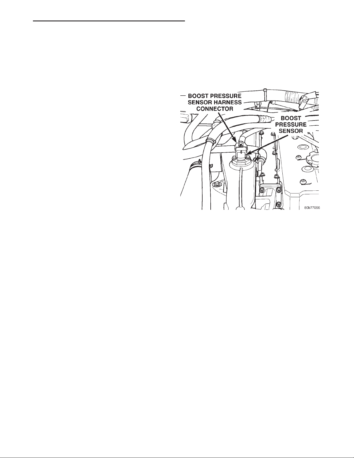
The Boost Pressure Sensor is mounted to the top of
the intake manifold (Fig. 3). It is a sensor that measures both manifold vacuum and turbo boost, and it
also contains an integrated intake air temperature
sensor. The Boost Pressure Sensor takes the place of
the Mass Air Flow (MAF). In the Intake Air Temperature Sensor component, there is a ceramic element
that changes its resistance based on temperature.
The ceramic element is part of an electronic circuit
connected to the PCM, and has a voltage applied to
it. The ceramic element is exposed to the air inside
the intake. This air has a cooling effect on the
ceramic element, and its resistance changes. This
causes the voltage flowing through the intake air
temperature circuit to vary. The voltage signal produced by the Intake Air Temperature Sensor changes
inversely to the temperature, and is measured by the
PCM. As a general rule, when the temperature of the
air in the intake is high, the voltage signal produced
by the Intake Air Temperature Sensor is low. The
component of the Boost Pressure Sensor that measures manifold vacuum and turbo boost produces a
voltage signal that is proportional to the pressure in
the intake manifold. When the intake manifold pressure is low, the voltage is low, and when the pressure
is high, the voltage is high. The PCM uses the voltage signals from the Boost Pressure Sensor, and the
Intake Air Temperature Sensor to determine the
amount of air flowing through the intake manifold.
Fig. 3 Boost Pressure Sensor Location
VEHICLE THEFT ALARM
The PCM can learn if the vehicle has a Vehicle
Theft Alarm (VTA) system. Once it detects the vehicle having VTA, the controller can ONLY BE
USED ON VEHICLES WITH VTA.
If the PCM is put it on a vehicle without VTA the
Glow Plug Lamp will start to blink and the vehicle
will not start.
The PCM cannot be flashed to remove the VTA.
BATTERY VOLTAGE—PCM INPUT
The battery voltage input provides power to the
PCM. It also informs the PCM what voltage level is
being supplied by the generator once the vehicle is
running.
The battery input also provides the voltage that is
needed to keep the PCM memory alive. The memory
stores Diagnostic Trouble Code (DTC) messages.
Trouble codes will still be stored even if the battary
voltage is lost.
SENSOR RETURN—ECM/PCM INPUT (ANALOG
GROUND)
Sensor Return provides a low noise Analog ground
reference for all system sensors.
IGNITION CIRCUIT SENSE—MSA/PCM INPUT
The ignition circuit sense input signals the MSA
and PCM that the ignition (key) switch has been
Page 26
14 - 26 FUEL SYSTEM—2.5L DIESEL ENGINE XJ
DESCRIPTION AND OPERATION (Continued)
turned to the ON position. This signal initiates the
glow plug control routine to begin the “pre–heat”
cycle.
IGNITION CIRCUIT SENSE—PCM INPUT
The ignition circuit sense input signals the PCM
that the ignition (key) switch has been turned to the
ON position. This signal initiates the glow plug control routine to begin the “pre–heat” cycle.
POWER GROUND
Provides a common ground for power devices (solenoid and relay devices).
NEEDLE MOVEMENT OR INSTRUMENTED
FIRST INJECTOR—ECM INPUT
This input from the ECM supplies a constant 30
mA electrical current source for the first injector sensor. It will vary the voltage to this sensor when it
senses a mechanical movement within the injector
needle (pintle) of the number–1 cylinder fuel injector.
When this voltage has been determined by the ECM,
it will then control an output to the fuel timing solenoid (the fuel timing solenoid is located on the fuel
injection pump). Also refer to Fuel Injection Pump for
additional information.
The first injector sensor is a magnetic (inductive)
type.
The first injector sensor is used only on the fuel
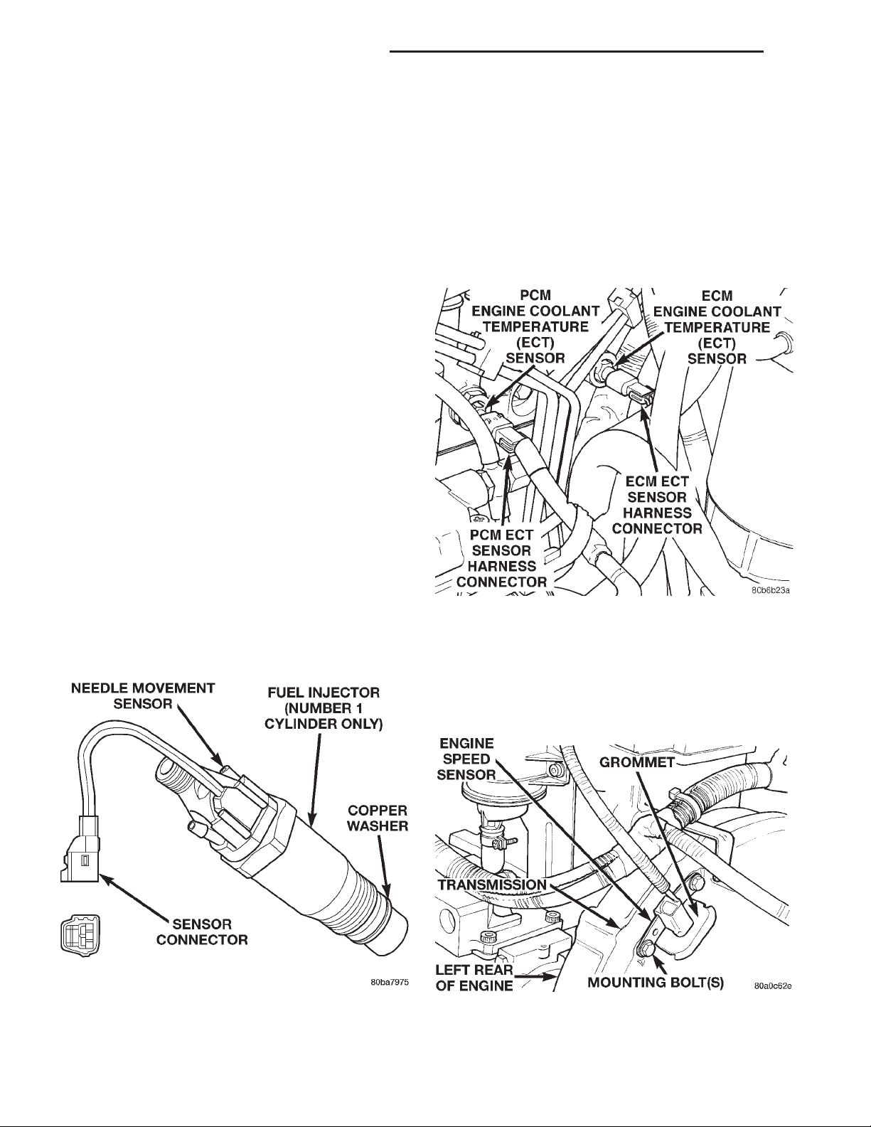
injector for the number–1 cylinder (Fig. 4). It is not
used on the injectors for cylinders number 2, 3, or 4.
FUEL INJECTOR SENSOR—GROUND
ENGINE COOLANT TEMPERATURE SENSOR—
ECM/PCM INPUT
The 0–5 volt input from this sensor tells the ECM
and PCM the temperature of the engine coolant.
Based on the voltage received at the ECM, it will
then determine operation of the fuel timing solenoid,
glow plug relay, electrical vacuum modulator (emission component) and generator (charging system).
The sensor is located on the side of the #3 cylinder
head near the rear of fuel injection pump (Fig. 5).
Fig. 5 Engine Coolant Temperature Sensor Location
ENGINE SPEED/CRANK POSITION SENSOR—
ECM INPUT
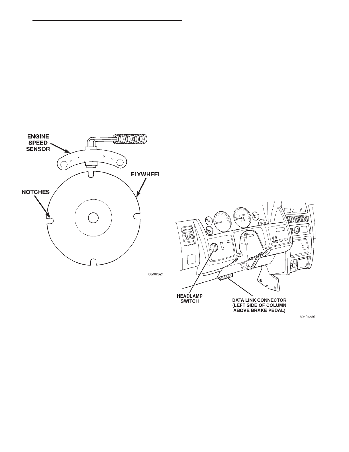
The engine speed sensor is mounted to the transmission bellhousing at the left/rear side of the engine
block (Fig. 6).
Fig. 4 Fuel Injector Sensor
Provides a low noise ground for the fuel injector
sensor only.
Fig. 6 Engine Speed Sensor Location
Page 27
XJ FUEL SYSTEM—2.5L DIESEL ENGINE 14 - 27
DESCRIPTION AND OPERATION (Continued)
The engine speed sensor produces its own output
signal. If this signal is not received, the ECM will not
allow the engine to start.
The engine speed sensor input is used in conjunction with the first injector sensor to establish fuel
injection pump timing.
The flywheel has four notches at its outer edge
(Fig. 7). Each notch is spaced equally every 90°. The
notches cause a pulse to be generated when they
pass under the speed sensor (Fig. 7). These pulses
are the input to the ECM. The input from this sensor
determines crankshaft position (in degrees) by monitoring the notches.
PCM will then remove the ground from the A/C relay.
This will deactivate the A/C compressor clutch. Also,
if the engine coolant reaches a temperature outside
normal of its normal range, or it overheats, the ECM
will deactivate the A/C clutch.
BRAKE SWITCH—ECM INPUT
When the brake light switch is activated, the ECM
receives an input indicating that the brakes are
being applied. After receiving this input, the ECM is
used to control the speed control system. There is a
Primary and a Secondary brake switch. The Secondary brake switch is closed until the brake pedal is
pressed.
DATA LINK CONNECTOR—PCM AND ECM
INPUT AND OUTPUT
The 16–way data link connector (diagnostic scan
tool connector) links the Diagnostic Readout Box
(DRB) scan tool with the PCM and ECM. The data
link connector is located under the instrument panel
near the bottom of steering column (Fig. 8).
Fig. 7 Speed Sensor Operation
The sensor also generates an rpm signal to the
ECM. This signal is used as an input for the control
of the generator field, vehicle speed control, and
instrument panel mounted tachometer.
If the engine speed sensor should fail, the system
is unable to compensate for the problem and the car
will stop.
AIR CONDITIONING (A/C) CONTROLS—ECM
INPUTS
The A/C control system information applies to factory installed air conditioning units.
A/C REQUEST SIGNAL: When either the A/C or
Defrost mode has been selected and the A/C low and
high–pressure switches are closed, an input signal is
sent to the ECM. The ECM uses this input to cycle
the A/C compressor through the A/C relay.
If the A/C low or high–pressure switch opens, the
ECM will not receive an A/C request signal. The
Fig. 8 Data Link Connector Location
VEHICLE SPEED SENSOR—ECM INPUT
The vehicle speed sensor is located in the extension
housing of the transmission (2WD) (Fig. 9) or on the
transfer case extension housing (Fig. 10). The sensor
input is used by the ECM to determine vehicle speed
and distance traveled.
The speed sensor generates 8 pulses per sensor
revolution. These signals, in conjunction with a
closed throttle signal from the accelerator pedal position sensor, indicate an idle deceleration to the ECM.
When the vehicle is stopped at idle, a released pedal
signal is received by the ECM (but a speed sensor
signal is not received).
Page 28
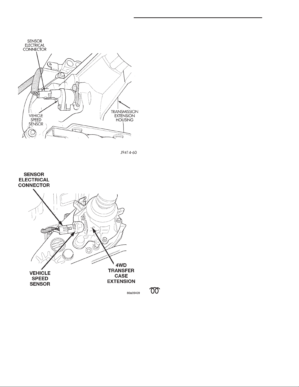
14 - 28 FUEL SYSTEM—2.5L DIESEL ENGINE XJ
DESCRIPTION AND OPERATION (Continued)
speed has been selected. The Resume input indicates
to the ECM that the previous fixed speed is
requested.
Speed control operation will start at 50 km/h–142
km/h (35–85 mph). The upper range of operation is
not restricted by vehicle speed. Inputs that effect
speed control operation are vehicle speed sensor and
accelerator pedal position sensor.
Refer to Group 8H for further speed control information.
ASD RELAY—ECM INPUT
A 12 volt signal at this input indicates to the ECM
that the ASD relay has been activated. The ASD
relay is located in the PDC. The PDC is located next
to the battery in the engine compartment. For the
location of the relay within the PDC, refer to label on
PDC cover.
This input is used only to sense that the ASD relay
is energized. If the ECM does not see 12 volts (+) at
this input when the ASD relay should be activated, it
will set a Diagnostic Trouble Code (DTC).
Fig. 9 Vehicle Speed Sensor—Typical
FIVE VOLT POWER—ECM/PCM OUTPUT
This circuit supplies approximately 5 volts to
power the Accelerator Pedal Position Sensor, and the
Boost / Pressure Sensor.
Fig. 10 Vehicle Speed Sensor—4 Wheel Drive
In addition to determining distance and vehicle
speed, the output from the sensor is used to control
speed control operation.
SPEED CONTROL—ECM INPUT
The speed control system provides five separate
inputs to the ECM: On/Off, Set, Resume/Accel, Cancel, and Decel. The On/Off input informs the ECM
that the speed control system has been activated.
The Set input informs the ECM that a fixed vehicle
ENGINE COOLANT GAUGE—PCM OUTPUT
Refer to the Instrument Panel and Gauges group
for additional information.
ENGINE OIL PRESSURE GAUGE—PCM
OUTPUT
Refer to the Instrument Panel and Gauges group
for additional information.
GLOW PLUG LAMP—PCM OUTPUT
The Glow Plug lamp (malfunction indicator lamp)
illuminates on the message center each time the ignition (key) switch is turned on. It will stay on for
about two seconds as a bulb test.
Fig. 11 Glow Plug Lamp Symbol
SPEED CONTROL—PCM OUTPUTS
These two circuits control the fuel quantity actuator to regulate vehicle speed. Refer to Group 8H for
Speed Control information.
AIR CONDITIONING RELAY—ECM OUTPUT
This circuit controls a ground signal for operation
of the A/C clutch relay. Also refer to Air Conditioning
Page 29
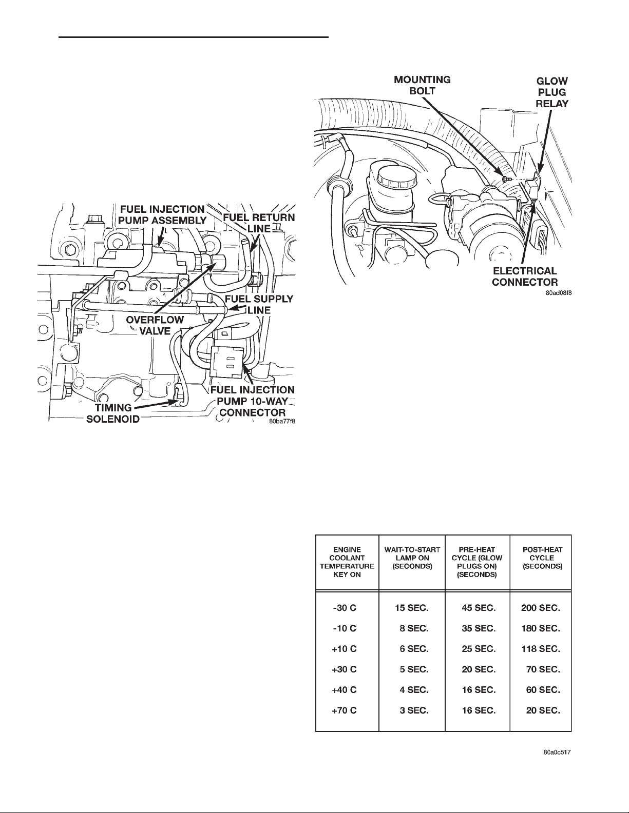
XJ FUEL SYSTEM—2.5L DIESEL ENGINE 14 - 29
DESCRIPTION AND OPERATION (Continued)
(A/C) Controls—ECM Input for additional information.
The A/C relay is located in the Power Distribution
Center (PDC). The PDC is located next to the battery
in the engine compartment. For the location of the
relay within the PDC, refer to label on PDC cover.
TIMING SOLENOID—ECM OUTPUT
The timing solenoid is located on the bottom of the
fuel injection pump (Fig. 12).
Fig. 13 Glow Plug Relay Location
plug relay is activated, it will control the 12V+ 100
amp circuit for the operation of the four glow plugs.
With a cold engine, the glow plug relay and glow
plugs may be activated for a maximum time of 200
seconds. Refer to the following Glow Plug Control
chart for a temperature/time comparison of glow plug
relay operation.
In this chart, Pre–Heat and Post–Heat times are
mentioned. Pre–heat is the amount of time the glow
Fig. 12 Timing Solenoid
This 12(+) volt, pulse width modulated (duty–cycle)
output controls the amount of fuel timing (advance)
in the fuel injection pump. The higher the duty–cycle, the lower the advance. The lower the duty–cycle,
the more advanced the fuel timing.
The duty–cycle is determined by the ECM from
inputs it receives from the fuel injector sensor and
engine speed sensor.
plug relay circuit is activated when the ignition (key)
switch is ON, but the engine has yet to be started.
Post–heat is the amount of time the glow plug relay
circuit is activated after the engine is operating. The
Glow Plug lamp will not be illuminated during the
post–heat cycle.
GLOW PLUG CONTROL
TACHOMETER—PCM OUTPUT
The PCM recieves engine rpm values from the
ECM controller, and then supplies engine rpm values
to the Body Controller that then supplies the instrument cluster mounted tachometer (if equipped). Refer
to Group 8E for tachometer information.
GLOW PLUG RELAY—ECM OUTPUT
When the ignition (key) switch is placed in the ON
position, a signal is sent to the ECM relating current
engine coolant temperature. This signal is sent from
the engine coolant temperature sensor.
After receiving this signal, the ECM will determine
if, when and for how long a period the glow plug
relay should be activated. This is done before, during
and after the engine is started. Whenever the glow
Page 30
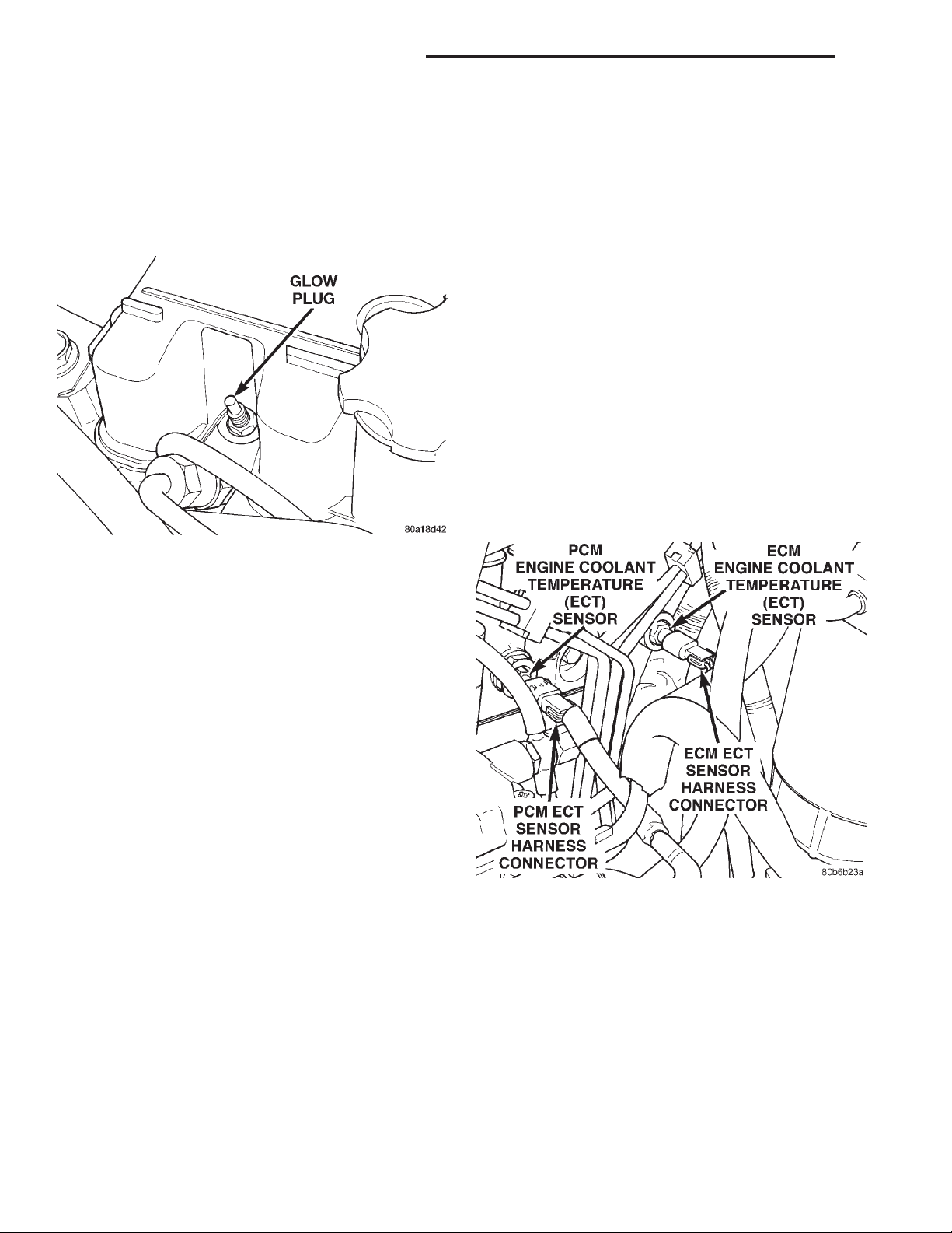
14 - 30 FUEL SYSTEM—2.5L DIESEL ENGINE XJ
DESCRIPTION AND OPERATION (Continued)
GLOW PLUGS
Glow plugs are used to help start a cold or cool
engine. The plug will heat up and glow to heat the
combustion chamber of each cylinder. An individual
plug is used for each cylinder. Each plug is threaded
into the cylinder head above the fuel injector (Fig.
14).
Fig. 14 Glow Plug
Each plug will momentarily draw approximately 25
amps of electrical current during the initial key–on
cycle. This is on a cold or cool engine. After heating,
the current draw will drop to approximately 9–12
amps per plug.
Total momentary current draw for all four plugs is
approximately 100 amps on a cold engine dropping to
a total of approximately 40 amps after the plugs are
heated.
Electrical operation of the glow plugs are controlled by the glow plug relay. Refer to the previous
Glow Plug Relay—ECM Output for additional information.
ASD RELAY TEST
To perform a test of the relay and its related circuitry, refer to the DRB scan tool. To test the relay
only, refer to Relays—Operation/Testing in this section of the group.
Diagnostic Trouble Codes: Refer to On-Board
Diagnostics in Group 25, Emission Control System
for a list of Diagnostic Trouble Codes (DTC’s) for certain fuel system components.
ENGINE SPEED SENSOR TEST
To perform a test of the engine speed sensor and
its related circuitry, refer to the DRB scan tool.
Diagnostic Trouble Codes: Refer to On-Board
Diagnostics in Group 25, Emission Control System
for a list of Diagnostic Trouble Codes (DTC’s) for certain fuel system components.
ENGINE COOLANT TEMPERATURE SENSOR TEST
The sensor is located on the side of cylinder head
near the rear of fuel injection pump (Fig. 15).
ELECTRIC VACUUM MODULATOR (EVM)—ECM
OUTPUT
This circuit controls operation of the Electric Vacuum Modulator (EVM). The EVM controls operation
of the EGR valve.
Refer to Group 25, Emission Control System for
information. See Electric Vacuum Modulator.
DIAGNOSIS AND TESTING
DIESEL DIAGNOSTICS
The ECM controllers perform engine off diagnostic
tests, which may be heard for about 60 seconds after
turning the key off.
Fig. 15 Engine Coolant Temperature Sensor
Location
For a list of Diagnostic Trouble Codes (DTC’s) for
certain fuel system components, refer to On-Board
Diagnostics in Group 25, Emission Control System.
To test the sensor only, refer to the following:
(1) Disconnect wire harness connector from coolant
temperature sensor.
(2) Test the resistance of the sensor with a high
input impedance (digital) volt–ohmmeter. The resistance (as measured across the sensor terminals)
should be less than 1340 ohms with the engine
warm. Refer to the following Sensor Resistance
Page 31
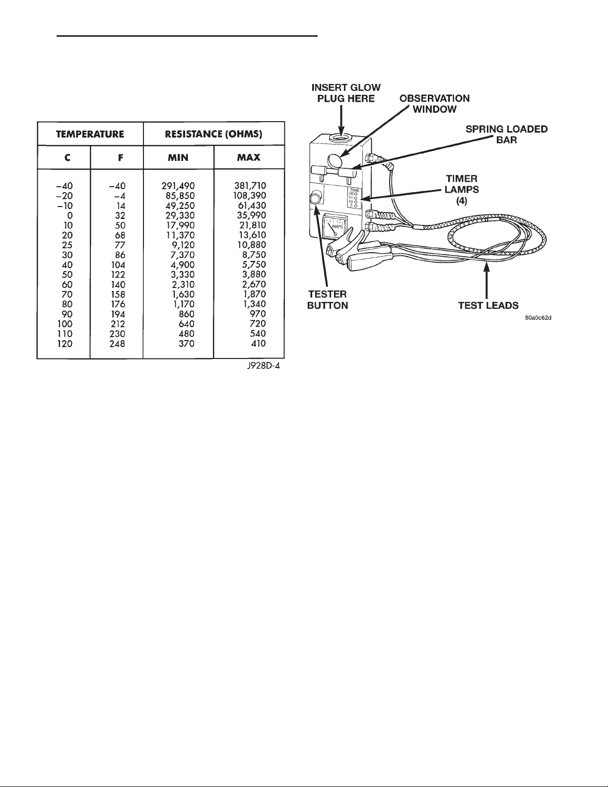
XJ FUEL SYSTEM—2.5L DIESEL ENGINE 14 - 31
DIAGNOSIS AND TESTING (Continued)
(OHMS) chart. Replace the sensor if it is not within
the range of resistance specified in the chart.
SENSOR RESISTANCE (OHMS)
(3) Test continuity of the wire harness. Do this
between the ECM wire harness connector and the
sensor connector terminal. Also test continuity of
wire harness to the sensor connector terminal. Refer
to Group 8W for wiring connector and circuitry information. Repair the wire harness if an open circuit is
indicated.
(4) After tests are completed, connect electrical
connector to sensor.
GLOW PLUG TEST
Hard starting or a rough idle after starting may be
caused by one or more defective glow plugs. Before
testing the glow plugs, a test of the glow plug relays
should be performed. This will ensure that 12V+ is
available at the plugs when starting the engine.
Refer to the Glow Plug Relay Test for information.
For accurate test results, the glow plugs should be
removed from the engine. The plugs must be checked
when cold. Do not check the plugs if the engine
has recently been operated. If plugs are
checked when warm, incorrect amp gauge
readings will result.
Use Churchill Glow Plug Tester DX.900 or an
equivalent (Fig. 16) for the following tests. This
tester is equipped with 4 timer lamps.
(1) Remove the glow plugs from the engine. Refer
to Glow Plug Removal/Installation.
(2) Attach the red lead of the tester to the 12V+
(positive) side of the battery.
Fig. 16 Typical Glow Plug Tester
(3) Attach the black lead of the tester to the 12V–
(negative) side of the battery.
(4) Fit the glow plug into the top of the tester and
secure it with the spring loaded bar (Fig. 16).
(5) Attach the third lead wire of the tester to the
electrical terminal at the end of the glow plug.
(6) When performing the test, the tester button
(Fig. 16) should be held continuously without release
for 20 seconds as indicated by the 4 timer lamps.
Each illuminated lamp represents a 5 second time
lapse.
(a) Press and hold the tester button (Fig. 16)
and note the amp gauge reading. The gauge reading should indicate a momentary, initial current
draw (surge) of approximately 25 amps. After the
initial surge, the amp gauge reading should begin
to fall off. The glow plug tip should start to glow
an orange color after 5 seconds. If the tip did not
glow after 5 seconds, replace the glow plug. Before
discarding the glow plug, check the position of the
circuit breaker on the bottom of the plug tester. It
may have to be reset. Reset if necessary.
(b) Continue to hold the tester button while
observing the amp gauge and the 4 timer lamps.
When all 4 lamps are illuminated, indicating a 20
second time lapse, the amp gauge reading should
indicate a 9–12 amp current draw. If not, replace
the glow plug. Refer to Glow Plug Removal/Installation.
(7) Check each glow plug in this manner using one
20 second cycle. If the glow plug is to be retested, it
must first be allowed to cool to room temperature.
Page 32
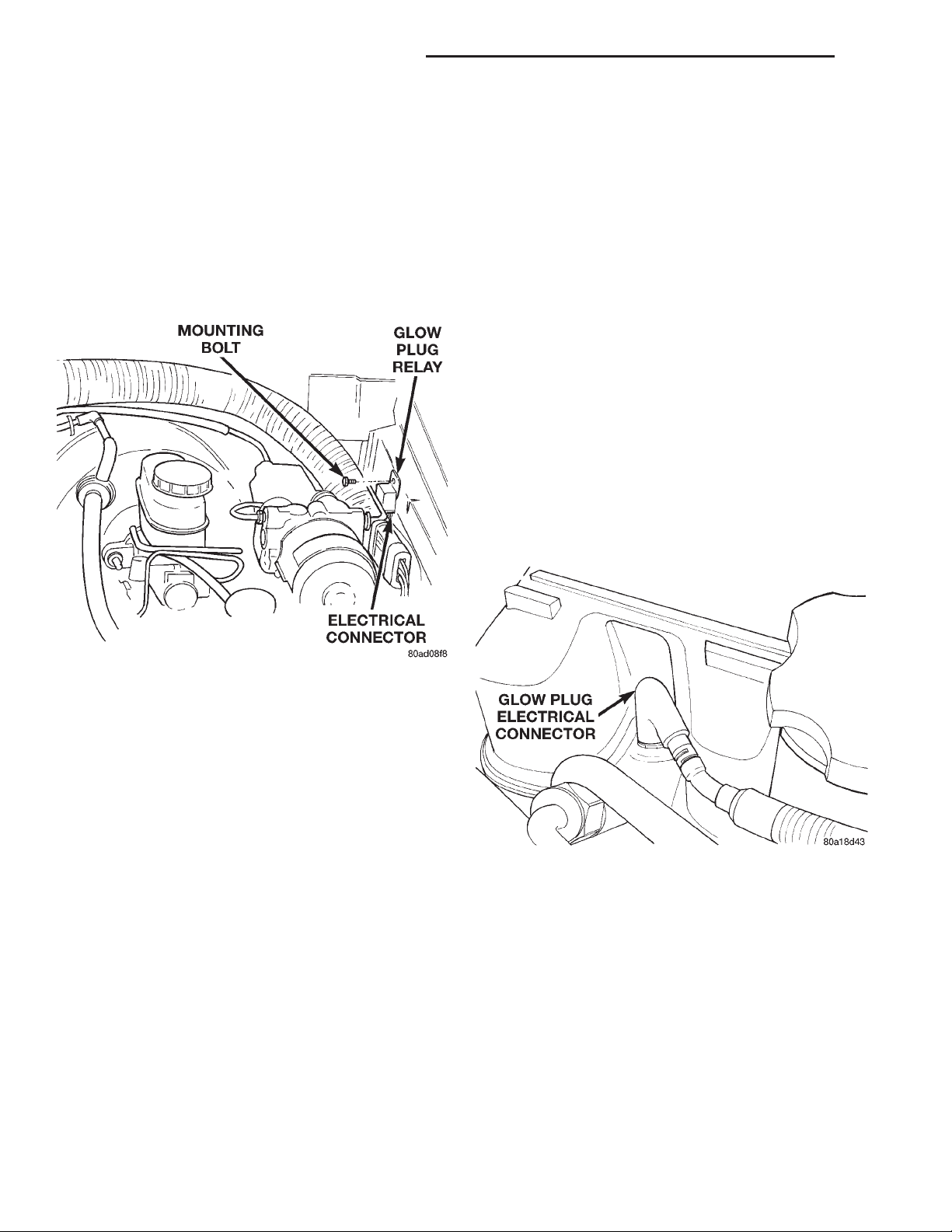
14 - 32 FUEL SYSTEM—2.5L DIESEL ENGINE XJ
DIAGNOSIS AND TESTING (Continued)
WARNING: THE GLOW PLUG WILL BECOME
EXTREMELY HOT (GLOWING) DURING THESE
TESTS. BURNS COULD RESULT IF IMPROPERLY
HANDLED. ALLOW THE GLOW PLUG TO COOL
BEFORE REMOVING FROM TESTER.
(8) Remove the glow plug from the tester.
GLOW PLUG RELAY TEST
The glow plug relay is located in the engine com-
partment on the left–inner fender (Fig. 17).
TESTING:
Disconnect and isolate the electrical connectors
(Fig. 18) at all four glow plugs. With the engine cool
or cold, and the key in the ON position, check for
10–12 volts + at each electrical connector. 10–12 volts
+ should be at each connector whenever the ECM is
operating in the pre–heat or post–heat cycles (refer
to the following Glow Plug Control chart). Be very
careful not to allow any of the four disconnected glow plug electrical connectors to contact a metal surface. When the key is turned to
the ON position, approximately 100 amps at 12
volts is supplied to these connectors. If 10–12
volts + is not available at each connector, check continuity of wiring harness directly to the relay. If continuity is good directly to the relay, the fault is either
with the relay or the relay input from the ECM. To
test the relay only, refer to Relays—Operation/Testing in this section of the group. If the relay test is
good, refer to the DRB scan tool.
Diagnostic Trouble Codes: Refer to On-Board
Diagnostics in Group 25, Emission Control System
for a list of Diagnostic Trouble Codes (DTC’s) for certain fuel system components.
Fig. 17 Glow Plug Relay Location
When the ignition (key) switch is placed in the ON
position, a signal is sent to the ECM relating current
engine coolant temperature. This signal is sent from
the engine coolant temperature sensor.
After receiving this signal, the ECM will determine
if, when and for how long a period the glow plug
relay should be activated. This is done before, during
and after the engine is started. Whenever the glow
plug relay is activated, it will control the 12V+ 100
amp circuit for the operation of the four glow plugs.
The Glow Plug lamp is tied to this circuit. Lamp
operation is also controlled by the ECM.
With a cold engine, the glow plug relay and glow
plugs may be activated for a maximum time of 200
seconds. Refer to the Glow Plug Control chart for a
temperature/time comparison of glow plug relay operation.
In this chart, Pre–Heat and Post–Heat times are
mentioned. Pre–heat is the amount of time the glow
plug relay circuit is activated when the ignition (key)
switch is ON, but the engine has yet to be started.
Post–heat is the amount of time the glow plug relay
circuit is activated after the engine is operating. The
Glow Plug lamp will not be illuminated during the
post–heat cycle.
Fig. 18 Wiring Connection at Glow Plug
RELAYS—OPERATION/TESTING
The following description of operation and
tests apply only to the ASD and other relays.
The terminals on the bottom of each relay are numbered (Fig. 19).
OPERATION
• Terminal number 30 is connected to battery voltage. For both the ASD and other relays, terminal 30
is connected to battery voltage at all times.
• The ECM grounds the coil side of the relay
through terminal number 85.
• Terminal number 86 supplies voltage to the coil
side of the relay.
Page 33
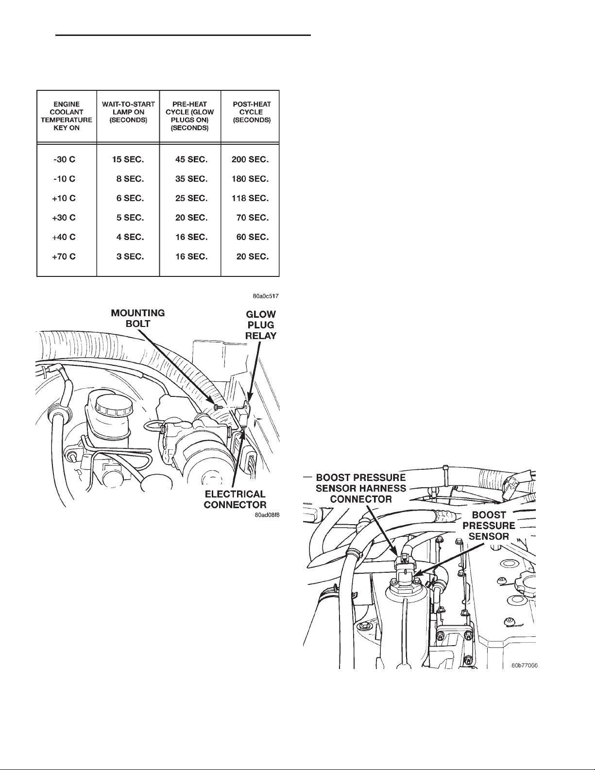
XJ FUEL SYSTEM—2.5L DIESEL ENGINE 14 - 33
DIAGNOSIS AND TESTING (Continued)
GLOW PLUG CONTROL
nals 85 and 86. The resistance should be between 75
65 ohms.
(3) Connect the ohmmeter between terminals 30
and 87A. The ohmmeter should show continuity
between terminals 30 and 87A.
(4) Connect the ohmmeter between terminals 87
and 30. The ohmmeter should not show continuity at
this time.
(5) Connect one end of a jumper wire (16 gauge or
smaller) to relay terminal 85. Connect the other end
of the jumper wire to the ground side of a 12 volt
power source.
(6) Connect one end of another jumper wire (16
gauge or smaller) to the power side of the 12 volt
power source. Do not attach the other end of the
jumper wire to the relay at this time.
WARNING: DO NOT ALLOW OHMMETER TO CONTACT TERMINALS 85 OR 86 DURING THIS TEST.
(7) Attach the other end of the jumper wire to
relay terminal 86. This activates the relay. The ohmmeter should now show continuity between relay terminals 87 and 30. The ohmmeter should not show
continuity between relay terminals 87A and 30.
(8) Disconnect jumper wires.
(9) Replace the relay if it did not pass the continuity and resistance tests. If the relay passed the tests,
it operates properly. Check the remainder of the ASD
and other relay circuits. Refer to group 8W, Wiring
Diagrams.
Fig. 19 Glow Plug Relay Location
• When the PCM de-energizes the ASD and other
relays, terminal number 87A connects to terminal 30.
This is the Off position. In the off position, voltage is
not supplied to the rest of the circuit. Terminal 87A
is the center terminal on the relay.
• When the ECM energizes the ASD and other
relays, terminal 87 connects to terminal 30. This is
the On position. Terminal 87 supplies voltage to the
rest of the circuit.
TESTING
The following procedure applies to the ASD and
other relays.
(1) Remove relay from connector before testing.
(2) With the relay removed from the vehicle, use
an ohmmeter to check the resistance between termi-
BOOST / PRESSURE SENSOR
Fig. 20 Boost Pressure Sensor Location
If the boost pressure sensor fails, the PCM records
a DTC into memory and continues to operate the
Page 34
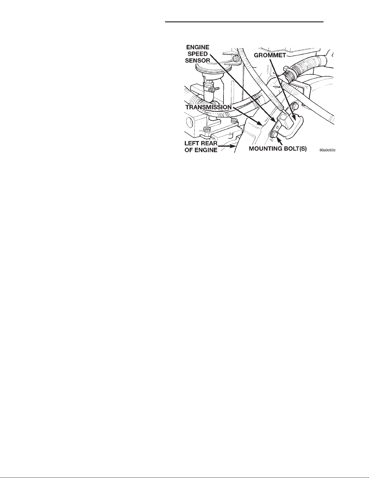
14 - 34 FUEL SYSTEM—2.5L DIESEL ENGINE XJ
DIAGNOSIS AND TESTING (Continued)
engine in one of the three “limp-in” modes. When the
PCM is operating in this mode, a loss of power will
be present, as if the turbocharger was not operating.
The best method for diagnosing faults with the boost
pressure sensor is with the DRB III scan tool. Diag-
nostic Trouble Codes: Refer to On-Board Diagnostics in Group 25, Emission Control System for a list
of Diagnostic Trouble Codes (DTC’s) for certain fuel
system components.
VEHICLE SPEED SENSOR TEST
To perform a test of the sensor and its related cir-
cuitry, refer to DRB scan tool.
Diagnostic Trouble Codes: Refer to On-Board
Diagnostics in Group 25, Emission Control System
for a list of Diagnostic Trouble Codes (DTC’s) for certain fuel system components.
Fig. 21 Engine Speed Sensor
DIAGNOSTIC TROUBLE CODES
For a list of Diagnostic Trouble Codes (DTC’s),
refer to Group 25, Emission Control System for information. See On-Board Diagnostics.
REMOVAL AND INSTALLATION
ASD RELAY
The ASD relay is located in the PDC. For the location of the relay within the PDC, refer to label on
PDC cover.
A/C CLUTCH RELAY
The A/C clutch relay is located in the PDC. For the
location of the relay within the PDC, refer to label on
PDC cover.
ENGINE SPEED SENSOR
The engine speed sensor is mounted to the transmission bellhousing at the rear of the engine block
(Fig. 21).
REMOVAL
(1) Disconnect the harness (on the sensor) from
the main electrical harness.
(2) Remove the sensor mounting bolts.
(3) Remove the sensor.
INSTALLATION
(1) Install the sensor flush against the opening in
the transmission housing.
(2) Install and tighten the sensor mounting bolt to
19 N·m (14 ft. lbs.) torque.
(3) Connect the electrical connector to the sensor.
ENGINE COOLANT TEMPERATURE SENSOR
The sensor is located on the side of cylinder head
near the rear of fuel injection pump.
REMOVAL
WARNING: HOT, PRESSURIZED COOLANT CAN
CAUSE INJURY BY SCALDING. COOLING SYSTEM
MUST BE PARTIALLY DRAINED BEFORE REMOVING THE COOLANT TEMPERATURE SENSOR.
REFER TO GROUP 7, COOLING.
(1) Partially drain cooling system. Refer to Group
7, Cooling.
(2) Disconnect electrical connector from sensor.
(3) Remove sensor from cylinder head.
INSTALLATION
(1) Install a new copper gasket to sensor.
(2) Install sensor to cylinder head.
(3) Tighten sensor to 18 N·m (13 ft. lbs.) torque.
(4) Connect electrical connector to sensor.
(5) Replace any lost engine coolant. Refer to Group
7, Cooling System.
GLOW PLUGS
The glow plugs are located above each fuel injector
(Fig. 22). Four individual plugs are used.
REMOVAL
(1) Disconnect the negative battery cable at the
battery.
(2) Clean the area around the glow plug with com-
pressed air before removal.
(3) Disconnect electrical connector (Fig. 23) at glow
plug.
(4) Remove the glow plug (Fig. 22) from cylinder
head.
Page 35
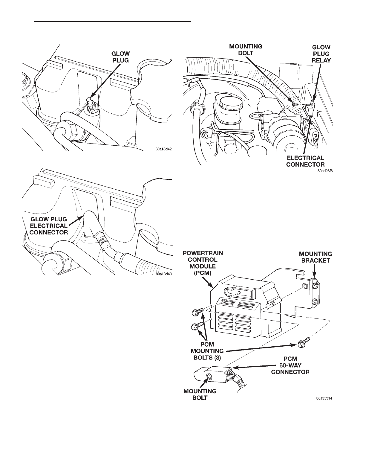
XJ FUEL SYSTEM—2.5L DIESEL ENGINE 14 - 35
REMOVAL AND INSTALLATION (Continued)
Fig. 22 Glow Plug
Fig. 24 Glow Plug Relay Location
(2) Install electrical connector to relay.
(3) Install relay to inner fender.
(4) Connect battery cable to battery.
Fig. 23 Glow Plug Electrical Connector
INSTALLATION
(1) Apply high–temperature anti–seize compound
to glow plug threads before installation.
(2) Install the glow plug into the cylinder head.
Tighten to 23 N·m (203 in. lbs.) torque.
(3) Connect battery cable to battery.
GLOW PLUG RELAY
The glow plug relay is located in the engine compartment on the left–inner fender (Fig. 24).
REMOVAL
(1) Disconnect the negative battery cable at the
battery.
(2) Remove relay mounting bolt.
(3) Disconnect electrical connector at relay and
remove relay.
INSTALLATION
(1) Check condition of electrical connector for damage or corrosion. Repair as necessary.
POWERTRAIN CONTROL MODULE (PCM)
The PCM is mounted to a bracket mounted to the
inner side of the right fender well behind the air
cleaner assembly (Fig. 25).
Fig. 25 PCM Location
REMOVAL
(1) Disconnect the negative battery cable at the
battery.
Page 36
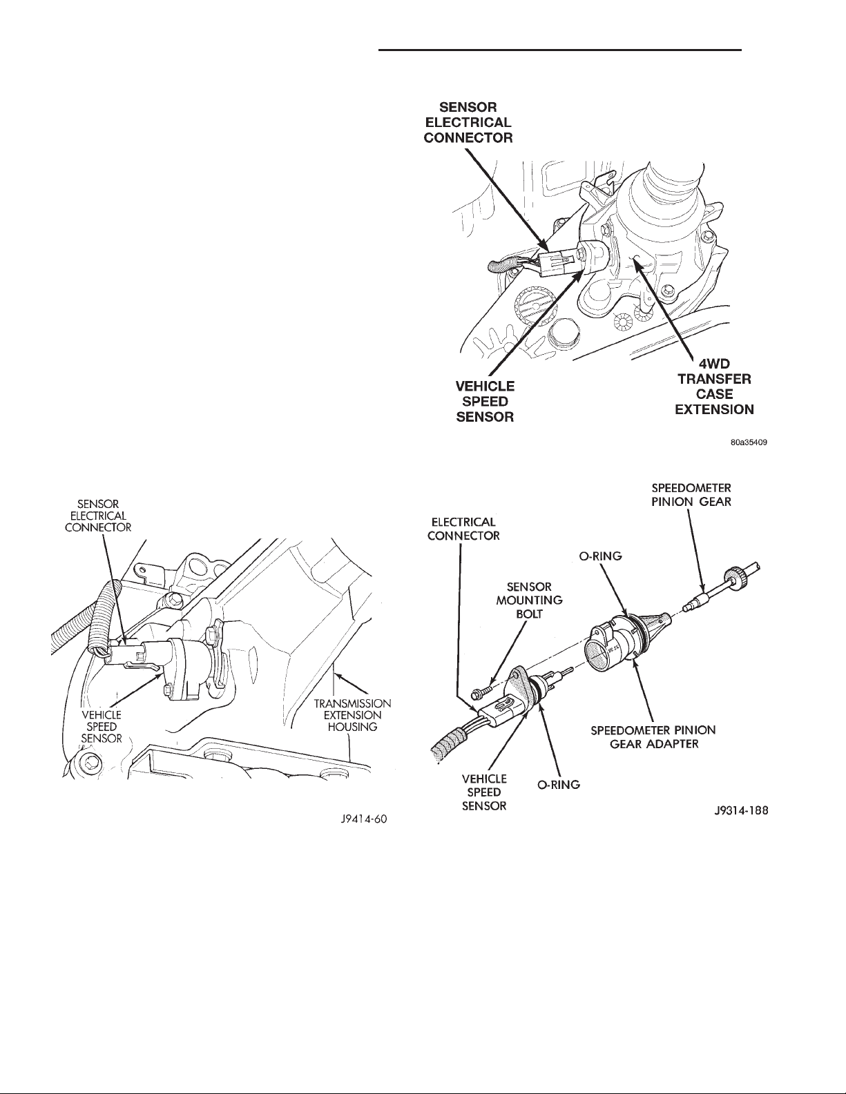
14 - 36 FUEL SYSTEM—2.5L DIESEL ENGINE XJ
REMOVAL AND INSTALLATION (Continued)
(2) Loosen the 60–Way connector (Fig. 25). The
electrical connector has a sliding bar which moves
inward to lock or outward to unlock.
(3) Remove the electrical connector by pulling
straight out.
(4) Remove PCM.
INSTALLATION
(1) After the PCM electrical connector has been
separated from the PCM, inspect the pins for corrosion, being spread apart, bent or misaligned. Also
inspect the pin heights in the connector. If the pin
heights are different, this would indicate a pin has
separated from the connector. Repair as necessary.
(2) Engage 60–way connector into PCM. Move
slide bar to lock connector.
(3) Connect negative cable to battery.
VEHICLE SPEED SENSOR
The vehicle speed sensor (Fig. 26) is located on the
extension housing of the transmission for 2 wheel
drive vehicle, or on the transfer case housing for 4
wheel drive vehicles (Fig. 27).
Fig. 27 Vehicle Speed Sensor Location—4WD
Fig. 26 Vehicle Speed Sensor Location—2 Wheel
Drive
REMOVAL
(1) Raise and support vehicle.
(2) Clean the area around the sensor before
removal.
(3) Disconnect the electrical connector from the
sensor (Fig. 28).
(4) Remove the sensor mounting bolt (Fig. 28).
Fig. 28 Sensor Removal/Installation—Typical
(5) Pull the sensor from the speedometer pinion
gear adapter for removal.
INSTALLATION
(1) Install new sensor into speedometer gear
adapter.
(2) Tighten sensor mounting bolt. To prevent damage to sensor or speedometer adapter, be sure the
sensor is mounted flush to the adapter before tightening.
(3) Connect electrical connector to sensor.
Page 37
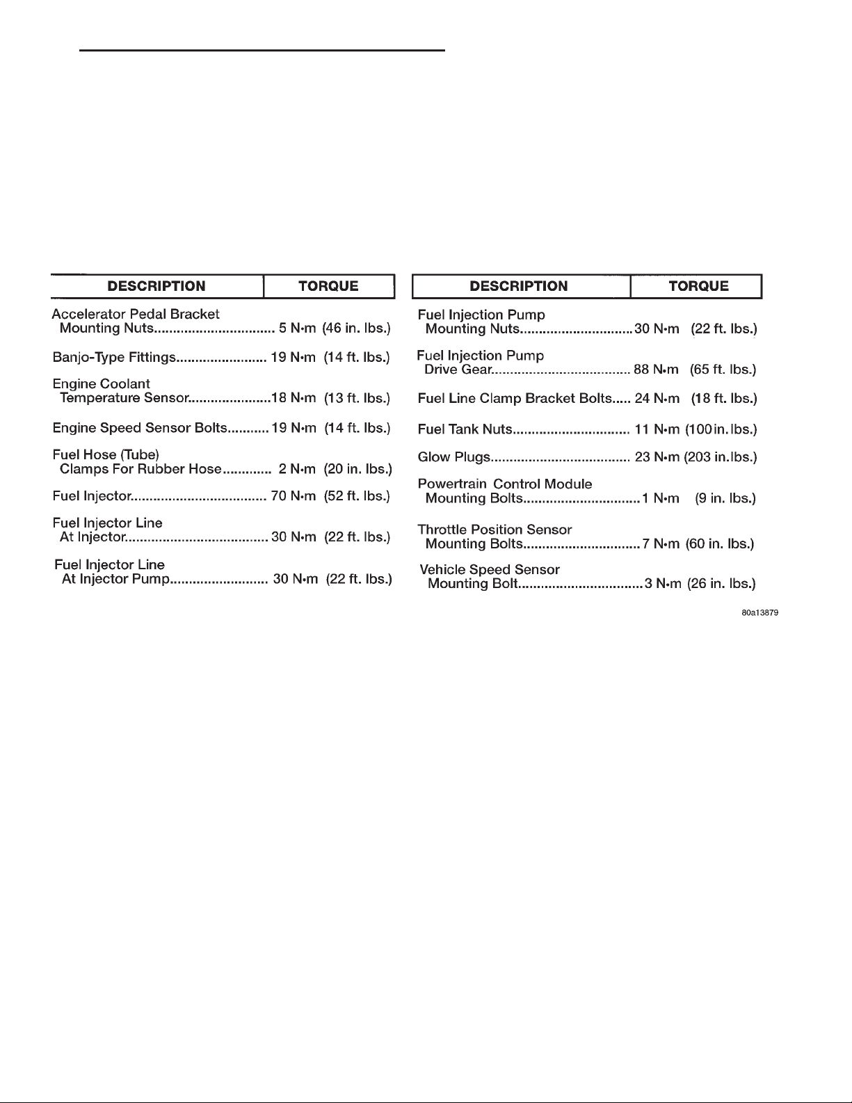
XJ FUEL SYSTEM—2.5L DIESEL ENGINE 14 - 37
SPECIFICATIONS
GLOW PLUG CURRENT DRAW
Initial Current Draw: Approximately 22–25
amps per plug.
After 20 seconds of operation: Approximately
9–12 amps per plug.
TORQUE CHART—2.5L DIESEL
Page 38

 Loading...