

Page 1
XJ FUEL SYSTEM 14 - 1
FUEL SYSTEM
CONTENTS
page page
FUEL DELIVERY SYSTEM ................... 1 FUEL INJECTION SYSTEM ................. 23
FUEL DELIVERY SYSTEM
INDEX
page page
DESCRIPTION AND OPERATION
FUEL DELIVERY SYSTEM ..................3
FUEL FILTER/FUEL PRESSURE REGULATOR . . . 4
FUEL GAUGE SENDING UNIT ............... 4
FUEL INJECTORS ........................ 5
FUEL PUMP .............................3
FUEL PUMP MODULE ..................... 3
FUEL RAIL/FUEL DAMPER—2.5L ENGINE ...... 5
FUEL RAIL—4.0L ENGINE .................. 5
FUEL REQUIREMENTS .................... 1
FUEL TANK ............................. 5
FUEL TANK FILLER TUBE CAP .............. 6
PCM REPLACEMENT ..................... 1
QUICK-CONNECT FITTINGS ................ 6
ROLLOVER VALVE(S) ..................... 5
DIAGNOSIS AND TESTING
FUEL GAUGE SENDING UNIT ..............10
FUEL INJECTOR TEST ...................10
FUEL PRESSURE LEAK DOWN TEST ......... 7
FUEL PUMP AMPERAGE TEST .............. 8
FUEL PUMP CAPACITY TEST ............... 7
FUEL PUMP PRESSURE TEST—ALL ENGINES
WITH PRESSURE TEST PORT ............. 6
SERVICE PROCEDURES
FUEL SYSTEM PRESSURE RELEASE
PROCEDURE ......................... 10
FUEL TUBES/LINES/HOSES AND CLAMPS .... 10
QUICK-CONNECT FITTINGS ............... 11
REMOVAL AND INSTALLATION
ACCELERATOR PEDAL ................... 20
FUEL FILTER/FUEL PRESSURE REGULATOR . . 13
FUEL GAUGE SENDING UNIT .............. 15
FUEL INJECTOR RAIL—2.5L ENGINE ........ 16
FUEL INJECTOR RAIL—4.0L ENGINE ........ 17
FUEL INJECTORS .......................18
FUEL PUMP INLET FILTER ................ 15
FUEL PUMP MODULE ....................14
FUEL TANK ............................ 18
FUEL TANK FILLER TUBE CAP ............. 20
THROTTLE CABLE ...................... 21
SPECIFICATIONS
FUEL SYSTEM PRESSURE ................ 22
FUEL TANK CAPACITY ...................22
TORQUE CHART ........................ 22
DESCRIPTION AND OPERATION
PCM REPLACEMENT
USE THE DRB SCAN TOOL TO REPROGRAM
THE NEW POWERTRAIN CONTROL MODULE
(PCM) WITH THE VEHICLES ORIGINAL IDENTIFICATION NUMBER (VIN) AND THE VEHICLES ORIGINAL MILEAGE. IF THIS STEP IS
NOT DONE, A DIAGNOSTIC TROUBLE CODE
(DTC) MAY BE SET.
FUEL REQUIREMENTS
Your engine is designed to meet all emissions regulations and provide excellent fuel economy and performance when using high quality unleaded gasoline
having an octane rating of 87. The use of premium
gasoline is not recommended. The use of premium
gasoline will provide no benefit over high quality regular gasoline, and in some circumstances may result
in poorer performance.
Light spark knock at low engine speeds is not
harmful to your engine. However, continued heavy
spark knock at high speeds can cause damage and
immediate service is required. Engine damage result-
Page 2

14 - 2 FUEL SYSTEM XJ
DESCRIPTION AND OPERATION (Continued)
ing from operation with a heavy spark knock may
not be covered by the new vehicle warranty.
Poor quality gasoline can cause problems such as
hard starting, stalling and hesitations. If you experience these symptoms, try another brand of gasoline
before considering service for the vehicle.
The American Automobile Manufacturers Association, AAMA, has issued gasoline specifications to
define the minimum fuel properties necessary to
deliver enhanced performance and durability for your
vehicle. Chrysler recommends the use of gasoline
that meet the AAMA specifications if they are available.
REFORMULATED GASOLINE
Many areas of the country require the use of
cleaner burning gasoline referred to as “reformulated” gasoline. Reformulated gasoline contain oxygenates, and are specifically blended to reduce vehicle
emissions and improve air quality.
Chrysler strongly supports the use of reformulated
gasoline. Properly blended reformulated gasoline will
provide excellent performance and durability for the
engine and fuel system components.
GASOLINE/OXYGENATE BLENDS
Some fuel suppliers blend unleaded gasoline with
oxygenates such as 10% ethanol, MTBE, and ETBE.
Oxygenates are required in some areas of the country
during the winter months to reduce carbon monoxide
emissions. Fuels blended with these oxygenates may
be used in your vehicle.
SULFUR IN GASOLINE
If you live in the northeast United States, your
vehicle may have been designed to meet California
low emission standards with clean-burning, low-sulfur, California gasoline. Gasoline sold outside of California is permitted to have higher sulfur levels
which may affect the performance of the vehicle’s catalytic converter. This may cause the Check Engine or
Service Engine Soon light to illuminate.
Illumination of either light while operating on high
sulfur gasoline does not necessarily mean your emission control system is malfunctioning. Chrysler recommends that you try a different brand of unleaded
gasoline having lower sulfur to determine if the problem is fuel related prior to returning your vehicle to
an authorized dealer for service.
CAUTION: If the Check Engine or Service Engine
Soon light is flashing, immediate service is
required; see on-board diagnostics system section.
MATERIALS ADDED TO FUEL
All gasoline sold in the United States and Canada
are required to contain effective detergent additives.
Use of additional detergents or other additives is not
needed under normal conditions.
FUEL SYSTEM CAUTIONS
CAUTION: Follow these guidelines to maintain your
vehicle’s performance:
CAUTION: DO NOT use gasoline containing METHANOL. Gasoline containing methanol may damage
critical fuel system components.
MMT
MMT is a manganese-containing metallic additive
that is blended into some gasoline to increase octane.
Gasoline blended with MMT provide no performance
advantage beyond gasoline of the same octane number without MMT. Gasoline blended with MMT
reduce spark plug life and reduce emission system
performance in some vehicles. Chrysler recommends
that gasoline without MMT be used in your vehicle.
The MMT content of gasoline may not be indicated
on the gasoline pump; therefore, you should ask your
gasoline retailer whether or not his/her gasoline contains MMT.
It is even more important to look for gasoline without MMT in Canada because MMT can be used at
levels higher than allowed in the United States.
MMT is prohibited in Federal and California reformulated gasoline.
• The use of leaded gas is prohibited by Federal
law. Using leaded gasoline can impair engine performance, damage the emission control system, and
could result in loss of warranty coverage.
• An out-of-tune engine, or certain fuel or ignition
malfunctions, can cause the catalytic converter to
overheat. If you notice a pungent burning odor or
some light smoke, your engine may be out of tune or
malfunctioning and may require immediate service.
Contact your dealer for service assistance.
• When pulling a heavy load or driving a fully
loaded vehicle when the humidity is low and the temperature is high, use a premium unleaded fuel to
help prevent spark knock. If spark knock persists,
lighten the load, or engine piston damage may result.
• The use of fuel additives which are now being
sold as octane enhancers is not recommended. Most
of these products contain high concentrations of
methanol. Fuel system damage or vehicle performance problems resulting from the use of such fuels
or additives is not the responsibility of Chrysler Corporation and may not be covered under the new vehicle warranty.
Page 3
XJ FUEL SYSTEM 14 - 3
DESCRIPTION AND OPERATION (Continued)
NOTE: Intentional tampering with emissions control
systems can result in civil penalties being assessed
against you.
FUEL DELIVERY SYSTEM
The fuel delivery system consists of:
• the fuel pump module containing the electric
fuel pump, fuel filter/fuel pressure regulator, fuel
gauge sending unit (fuel level sensor) and a separate
fuel filter located at bottom of pump module
• fuel tubes/lines/hoses
• quick-connect fittings
• fuel injector rail
• fuel injectors
• fuel tank
• fuel tank filler/vent tube assembly
• fuel tank filler tube cap
• accelerator pedal
• throttle cable
Fuel is returned through the fuel pump module
and back into the fuel tank through the fuel filter/
fuel pressure regulator. A separate fuel return line
from the engine to the tank is not used.
The fuel tank assembly consists of: the fuel tank,
fuel pump module assembly, fuel pump module locknut/gasket, and rollover valve (refer to Group 25,
Emission Control System for rollover valve information).
A fuel filler/vent tube assembly using a pressure/
vacuum fuel filler cap is used. The fuel filler tube
contains a spring-loaded flap (door) located below the
fuel fill cap. The flap is used as a secondary way of
sealing the fuel tank if the fuel fill cap has not been
properly tightened. The flap is used as part of the
EVAP monitor system when the vehicle is equipped
with a Leak Detection Pump (LDP). The flap will be
installed to all fuel filler tubes (equipped/not
equipped with LDP and EVAP monitor system).
Also to be considered part of the fuel system is the
evaporation control system. This is designed to
reduce the emission of fuel vapors into the atmosphere. The description and function of the Evaporative Control System is found in Group 25, Emission
Control Systems.
Both fuel filters (at bottom of fuel pump module
and within fuel pressure regulator) are designed for
extended service. They do not require normal scheduled maintenance. Filters should only be replaced if
a diagnostic procedure indicates to do so.
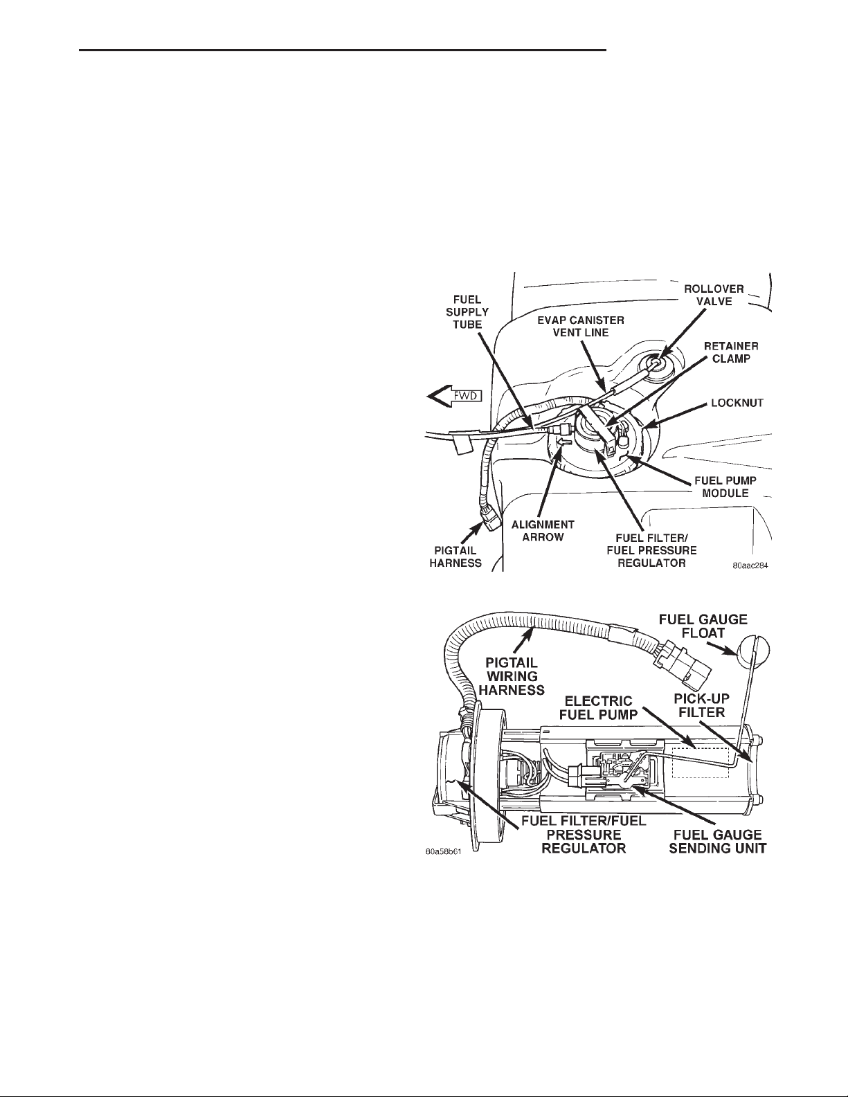
• A separate fuel pick-up filter (strainer)
• An electric fuel pump
• A threaded locknut to retain module to tank
• A gasket between tank flange and module
• Fuel gauge sending unit (fuel level sensor)
• Fuel supply tube (line) connection
The fuel gauge sending unit, pick-up filter and fuel
filter/fuel pressure regulator may be serviced separately. If the electrical fuel pump requires service,
the entire fuel pump module must be replaced.
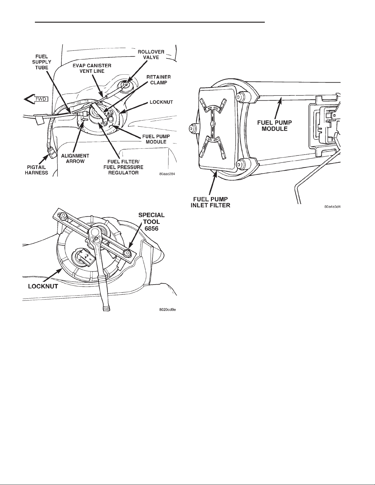
Fig. 1 Fuel Tank/Fuel Pump Module (Top View)
Fig. 2 Fuel Pump Module Components
FUEL PUMP
FUEL PUMP MODULE
The fuel pump module is installed in the top of the
fuel tank (Fig. 1) or (Fig. 2). The fuel pump module
contains the following components:
• A combination fuel filter/fuel pressure regulator
DESCRIPTION
The electric fuel pump is located inside of the fuel
pump module.
Page 4
14 - 4 FUEL SYSTEM XJ
DESCRIPTION AND OPERATION (Continued)
OPERATION
The fuel pump used in this system has a permanent
magnet electric motor. Fuel is drawn in through a filter
at the bottom of the module and pushed through the
electric motor gearset to the pump outlet.
Check Valve Operation: The pump outlet contains a one-way check valve to prevent fuel flow back
into the tank and to maintain fuel supply line pressure (engine warm) when pump is not operational. It
is also used to keep the fuel supply line full of gasoline when pump is not operational. After the vehicle
has cooled down, fuel pressure may drop to 0 psi
(cold fluid contracts), but liquid gasoline will remain
in fuel supply line between the check valve and fuel
injectors. Fuel pressure that has dropped to 0
psi on a cooled down vehicle (engine off) is a
normal condition. Refer to the Fuel Pressure Leak
Down Test for more information.
Voltage to operate the electric pump is supplied
through the fuel pump relay.
FUEL GAUGE SENDING UNIT
DESCRIPTION
The fuel gauge sending unit (fuel level sensor) is
attached to the side of the fuel pump module. The
sending unit consists of a float, an arm, and a variable resistor (track).
FUEL FILTER/FUEL PRESSURE REGULATOR
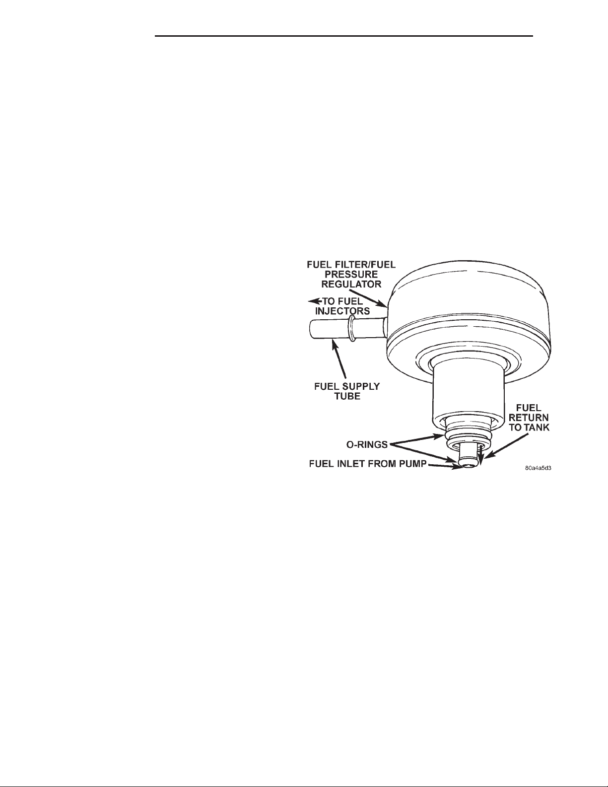
A combination fuel filter and fuel pressure regulator is used on all engines. It is located on the top of
fuel pump module (Fig. 1). A separate frame mounted
fuel filter is not used with any engine.
Fuel Pressure Regulator Operation: The pressure regulator is a mechanical device that is not controlled by engine vacuum or the Powertrain Control
Module (PCM).
The regulator is calibrated to maintain fuel system
operating pressure of approximately 339 kPa 6 34
kPa (49.2 psi 6 5 psi) at the fuel injectors. It contains a diaphragm, calibrated springs and a fuel
return valve. The internal fuel filter is also part of
the assembly.
OPERATION
The resistor track is used to send electrical signals to
the Powertrain Control Module (PCM) for fuel gauge
operation and for OBD II emission requirements.
For fuel gauge operation: As fuel level
increases, the float and arm move up. This decreases
the sending unit resistance, causing the fuel gauge to
read full. As fuel level decreases, the float and arm
move down. This increases the sending unit resistance causing the fuel gauge to read empty.
After this fuel level signal is sent to the PCM, the
PCM will transmit the data across the CCD bus circuits to the instrument panel. Here it is translated
into the appropriate fuel gauge level reading.
For OBD II emission monitor requirements:
voltage signal is sent from the resistor track on the
sending unit to the PCM to indicate fuel level. The purpose of this feature is to prevent the OBD II system
from recording/setting false misfire and fuel system
monitor trouble codes. The feature is activated if the
fuel level in the tank is less than approximately 15 percent of its rated capacity. If equipped with a Leak
Detection Pump (EVAP system monitor), this feature
will also be activated if the fuel level in the tank is
more than approximately 85 percent of its rated capacity.
A
Fig. 3 Fuel Filter/Fuel Pressure Regulator
Fuel is supplied to the filter/regulator by the electric fuel pump through an opening tube at the bottom of filter/regulator (Fig. 3).
The regulator acts as a check valve to maintain
some fuel pressure when the engine is not operating.
This will help to start the engine. A second check
valve is located at the outlet end of the electric fuel
pump. Refer to Fuel Pump—Description and
Operation for more information. Also refer to
the Fuel Pressure Leak Down Test and the Fuel
Pump Pressure Tests.
If fuel pressure at the pressure regulator exceeds
approximately 49 psi, an internal diaphragm closes
and excess fuel is routed back into the tank through
the pressure regulator. A separate fuel return line is
not used.
Page 5
XJ FUEL SYSTEM 14 - 5
DESCRIPTION AND OPERATION (Continued)
FUEL TANK
DESCRIPTION
The fuel tank is constructed of a plastic material.
Its main functions are for fuel storage and for placement of the fuel pump module.
OPERATION
All models pass a full 360 degree rollover test
without fuel leakage. To accomplish this, fuel and
vapor flow controls are required for all fuel tank connections.
A rollover valve(s) is mounted into the top of the
fuel tank (or pump module). Refer to Emission Control System for rollover valve information.
An evaporation control system is connected to the
rollover valve(s) to reduce emissions of fuel vapors
into the atmosphere. When fuel evaporates from the
fuel tank, vapors pass through vent hoses or tubes to
a charcoal canister where they are temporarily held.
When the engine is running, the vapors are drawn
into the intake manifold. Certain models are also
equipped with a self-diagnosing system using a Leak
Detection Pump (LDP). Refer to Emission Control
System for additional information.
injector pulse width based on various inputs it
receives.
During start up, battery voltage is supplied to the
injectors through the ASD relay. When the engine is
operating, voltage is supplied by the charging system. The PCM determines injector pulse width based
on various inputs.
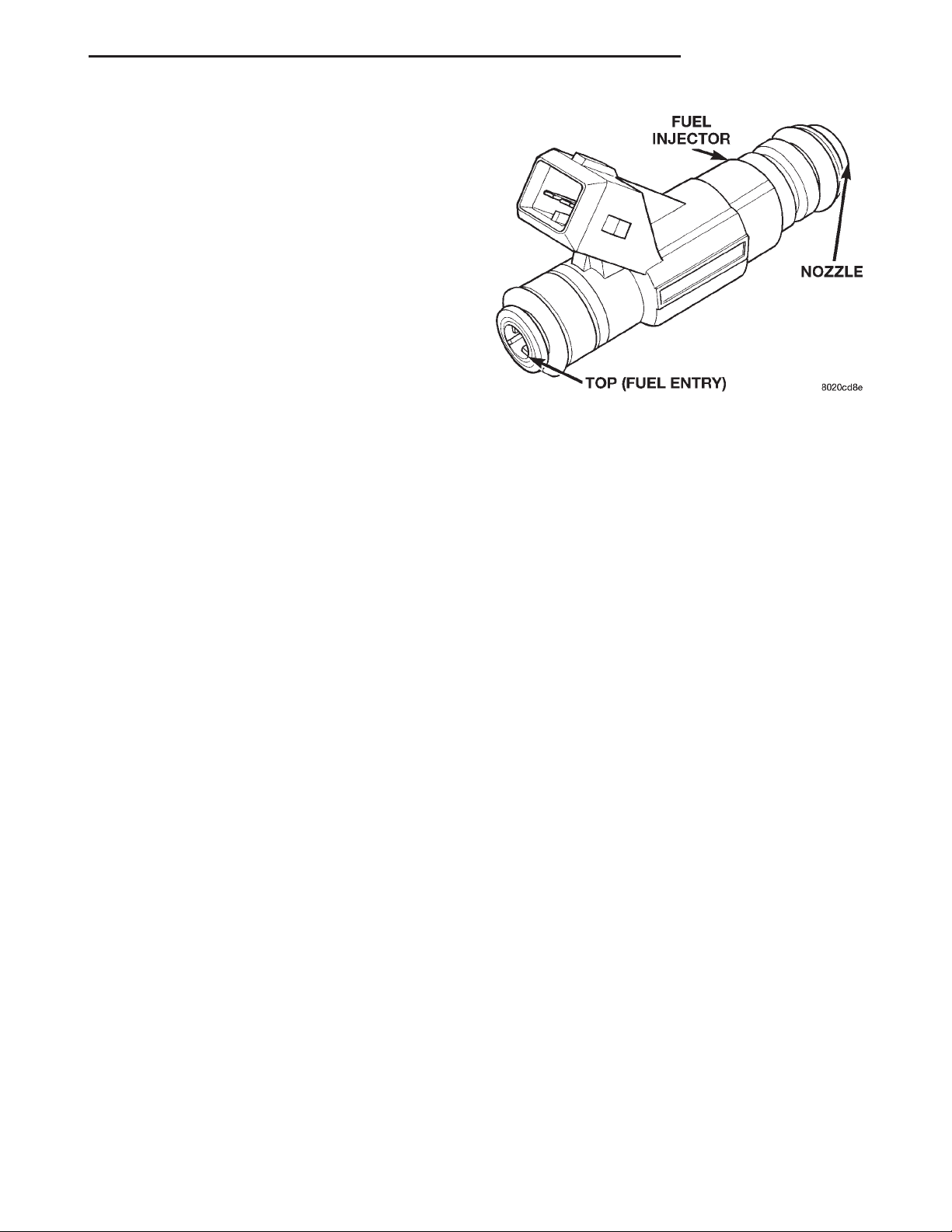
Fig. 4 Fuel Injector—Typical
FUEL RAIL/FUEL DAMPER—2.5L ENGINE
ROLLOVER VALVE(S)
Refer to Group 25, Emission Control System for
information.
FUEL INJECTORS
The fuel injectors (Fig. 4) are electrical solenoids.
The injector contains a pintle that closes off an orifice at the nozzle end. When electric current is supplied to the injector, the armature and needle move a
short distance against a spring, allowing fuel to flow
out the orifice. Because the fuel is under high pressure, a fine spray is developed in the shape of a pencil stream. The spraying action atomizes the fuel,
adding it to the air entering the combustion chamber.
An individual fuel injector is used for each individual cylinder. The top (fuel entry) end of the injector is
attached into an opening on the fuel rail.
The nozzle (outlet) ends of the injectors are positioned into openings in the intake manifold just
above the intake valve ports of the cylinder head.
The engine wiring harness connector for each fuel
injector is equipped with an attached numerical tag
(INJ 1, INJ 2 etc.). This is used to identify each fuel
injector.
The injectors are energized individually in a
sequential order by the powertrain control module
(PCM). The PCM will adjust injector pulse width by
switching the ground path to each individual injector
on and off. Injector pulse width is the period of time
that the injector is energized. The PCM will adjust
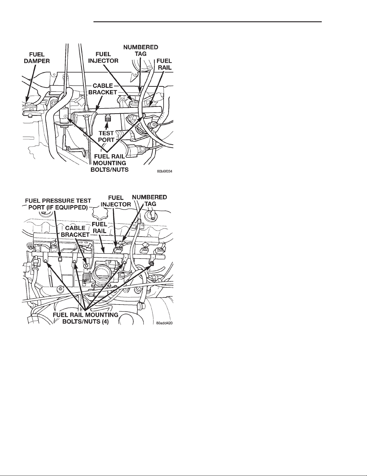
The fuel rail supplies the necessary fuel to each
individual fuel injector and is mounted to the intake
manifold (Fig. 5). On the 2.5L engine, a fuel
damper is located at the front of the fuel rail (Fig.
5). The damper is used only to help control fuel pressure pulsations. These pulsations are the result of
the firing of the fuel injectors. It is not used as a
fuel pressure regulator. The fuel pressure regulator is
not mounted to the fuel rail on any engine. It is
located on the fuel tank mounted fuel pump module.
Refer to Fuel Filter/Fuel Pressure Regulator in this
group for information.
Depending on vehicle model/engine, the fuel rail
may/may not be equipped with a fuel pressure test
port. Refer to the Fuel Pump Pressure Test for additional information.
The fuel rail is not repairable.
FUEL RAIL—4.0L ENGINE
The fuel rail supplies the necessary fuel to each
individual fuel injector and is mounted to the intake
manifold (Fig. 6). The fuel pressure regulator is not
mounted to the fuel rail on any 4.0L engine. It is
located on the fuel tank mounted fuel pump module.
Refer to Fuel Filter/Fuel Pressure Regulator in this
group for information.
Depending on vehicle model/engine, the fuel rail
may/may not be equipped with a fuel pressure test
port. Refer to the Fuel Pump Pressure Test for additional information.
Page 6
14 - 6 FUEL SYSTEM XJ
DESCRIPTION AND OPERATION (Continued)
must be pressed (opened) to relieve fuel tank pressure.
QUICK-CONNECT FITTINGS
Different types of quick-connect fittings are used to
attach various fuel system components. These are: a
single-tab type, a two-tab type or a plastic retainer
ring type. Some are equipped with safety latch clips.
Refer to the Removal/Installation section for more
information.
CAUTION: The interior components (o-rings, spacers) of quick-connect fitting are not serviced separately, but new pull tabs are available for some
types. Do not attempt to repair damaged fittings or
fuel lines/tubes. If repair is necessary, replace the
complete fuel tube assembly.
Fig. 5 Fuel Rail/Fuel Damper—2.5L Engine
The fuel rail is not repairable.
DIAGNOSIS AND TESTING
Fig. 6 Fuel Rail—4.0L Engine
FUEL TANK FILLER TUBE CAP
The loss of any fuel or vapor out of filler neck is
prevented by the use of a pressure-vacuum fuel tank
filler tube cap. Relief valves inside the cap will
release fuel tank pressure at predetermined pressures. Fuel tank vacuum will also be released at predetermined values. This cap must be replaced by a
similar unit if replacement is necessary. This is in
order for the system to remain effective.
CAUTION: Remove fuel tank filler tube cap before
servicing any fuel system component. This is done
to help relieve tank pressure. If equipped with a
California emissions package and a Leak Detection
Pump (LDP), the secondary seal below the fill cap
FUEL PUMP PRESSURE TEST—ALL ENGINES
WITH PRESSURE TEST PORT
Use this test in conjunction with the Fuel Pump
Capacity Test, Fuel Pressure Leak Down Test and
Fuel Pump Amperage Test found elsewhere in this
group.
Check Valve Operation: The electric fuel pump
outlet contains a one-way check valve to prevent fuel
flow back into the tank and to maintain fuel supply
line pressure (engine warm) when pump is not operational. It is also used to keep the fuel supply line
full of gasoline when pump is not operational. After
the vehicle has cooled down, fuel pressure may drop
to 0 psi (cold fluid contracts), but liquid gasoline will
remain in fuel supply line between the check valve
and fuel injectors. Fuel pressure that has
dropped to 0 psi on a cooled down vehicle
(engine off) is a normal condition. When the elec-
tric fuel pump is activated, fuel pressure should
immediately (1–2 seconds) rise to specification.
All fuel systems are equipped with a fuel tank
module mounted, combination fuel filter/fuel pressure
regulator. The fuel pressure regulator is not controlled by engine vacuum.
WARNING: THE FUEL SYSTEM IS UNDER CONSTANT FUEL PRESSURE EVEN WITH THE ENGINE
OFF. BEFORE DISCONNECTING FUEL LINE AT
FUEL RAIL, THIS PRESSURE MUST BE RELEASED.
REFER TO THE FUEL SYSTEM PRESSURE
RELEASE PROCEDURE.
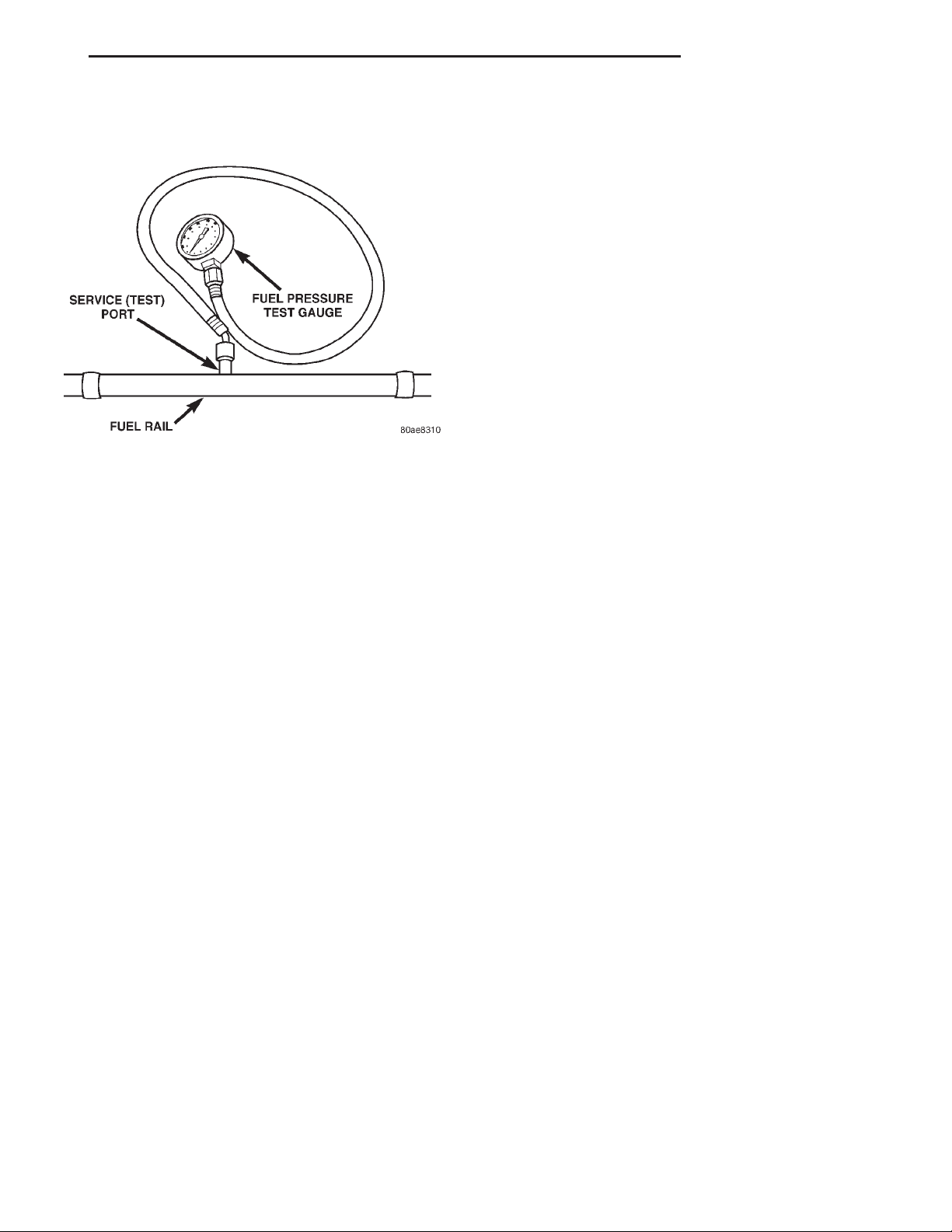
(1) Remove protective cap at fuel rail test port.
Connect the 0–414 kPa (0-60 psi) fuel pressure gauge
Page 7
XJ FUEL SYSTEM 14 - 7
DIAGNOSIS AND TESTING (Continued)
(from gauge set 5069) to test port pressure fitting on
fuel rail (Fig. 7).
Fig. 7 Fuel Pressure Test Gauge (Typical Gauge
Installation at Test Port)
(2) Start and warm engine and note pressure
gauge reading. Fuel pressure should be 339 kPa 6 34
kPa (49.2 psi 6 5 psi) at idle.
(3) If engine runs, but pressure is below 44.2 psi,
check for a kinked fuel supply line somewhere
between fuel rail and fuel pump module. If line is not
kinked, but specifications for either the Fuel Pump
Capacity, Fuel Pump Amperage or Fuel Pressure
Leak Down Tests were not met, replace fuel pump
module assembly. Refer to Fuel Pump Module
Removal/Installation.
(4) If operating pressure is above 54.2 psi, electric
fuel pump is OK, but fuel pressure regulator is defective. Replace fuel filter/fuel pressure regulator. Refer
to Fuel Filter/Fuel Pressure Regulator Removal/Installation for more information.
(5) Install protective cap to fuel rail test port.
FUEL PUMP CAPACITY TEST
Before performing this test, verify fuel pump
pressure. Refer to Fuel Pump Pressure Test.
Use this test in conjunction with the Fuel Pressure Leak Down Test.
(1) Release fuel system pressure. Refer to Fuel
Pressure Release Procedure.
(2) Disconnect fuel supply line at fuel rail. Refer to
Quick-Connect Fittings. Some engines may require
air cleaner housing removal before line disconnection.
(3) Obtain correct Fuel Line Pressure Test Adapter
Tool Hose. Tool number 6539 is used for 5/16” fuel
lines and tool number 6631 is used for 3/8” fuel lines.
(4) Connect correct Fuel Line Pressure Test
Adapter Tool Hose into disconnected fuel supply line.
Insert other end of Adaptor Tool Hose into a graduated container.
(5) Remove fuel fill cap.
(6) To activate fuel pump and pressurize system,
obtain DRB scan tool and actuate ASD Fuel System
Test.
(7) A good fuel pump will deliver at least 1/4 liter
of fuel in 7 seconds. Do not operate fuel pump for
longer than 7 seconds with fuel line disconnected as
fuel pump module reservoir may run empty.
(a) If capacity is lower than specification, but
fuel pump can be heard operating through fuel fill
cap opening, check for a kinked/damaged fuel supply line somewhere between fuel rail and fuel
pump module.
(b) If line is not kinked/damaged, and fuel pressure is OK, but capacity is low, replace fuel filter/
fuel pressure regulator. The filter/regulator may be
serviced separately on certain applications. Refer
to Fuel Filter/Fuel Pressure Regulator Removal/Installation for additional information.
(c) If both fuel pressure and capacity are low,
replace fuel pump module assembly. Refer to Fuel
Pump Module Removal/Installation.
FUEL PRESSURE LEAK DOWN TEST
Use this test in conjunction with the Fuel Pump
Pressure Test and Fuel Pump Capacity Test.
Check Valve Operation: The electric fuel pump
outlet contains a one-way check valve to prevent fuel
flow back into the tank and to maintain fuel supply
line pressure (engine warm) when pump is not operational. It is also used to keep the fuel supply line
full of gasoline when pump is not operational. After
the vehicle has cooled down, fuel pressure may drop
to 0 psi (cold fluid contracts), but liquid gasoline will
remain in fuel supply line between the check valve
and fuel injectors. Fuel pressure that has
dropped to 0 psi on a cooled down vehicle
(engine off) is a normal condition. When the elec-
tric fuel pump is activated, fuel pressure should
immediately (1–2 seconds) rise to specification.
Abnormally long periods of cranking to restart a
hot engine that has been shut down for a short
period of time may be caused by:
• Fuel pressure bleeding past a fuel injector(s).
• Fuel pressure bleeding past the check valve in
the fuel pump module.
(1) Disconnect the fuel inlet line at fuel rail. Refer
to Fuel Tubes/Lines/Hoses and Clamps in this section
of the group for procedures. On some engines, air
cleaner housing removal may be necessary before
fuel line disconnection.
(2) Obtain correct Fuel Line Pressure Test Adapter
Tool Hose. Tool number 6539 is used for 5/16” fuel
lines and tool number 6631 is used for 3/8” fuel lines.
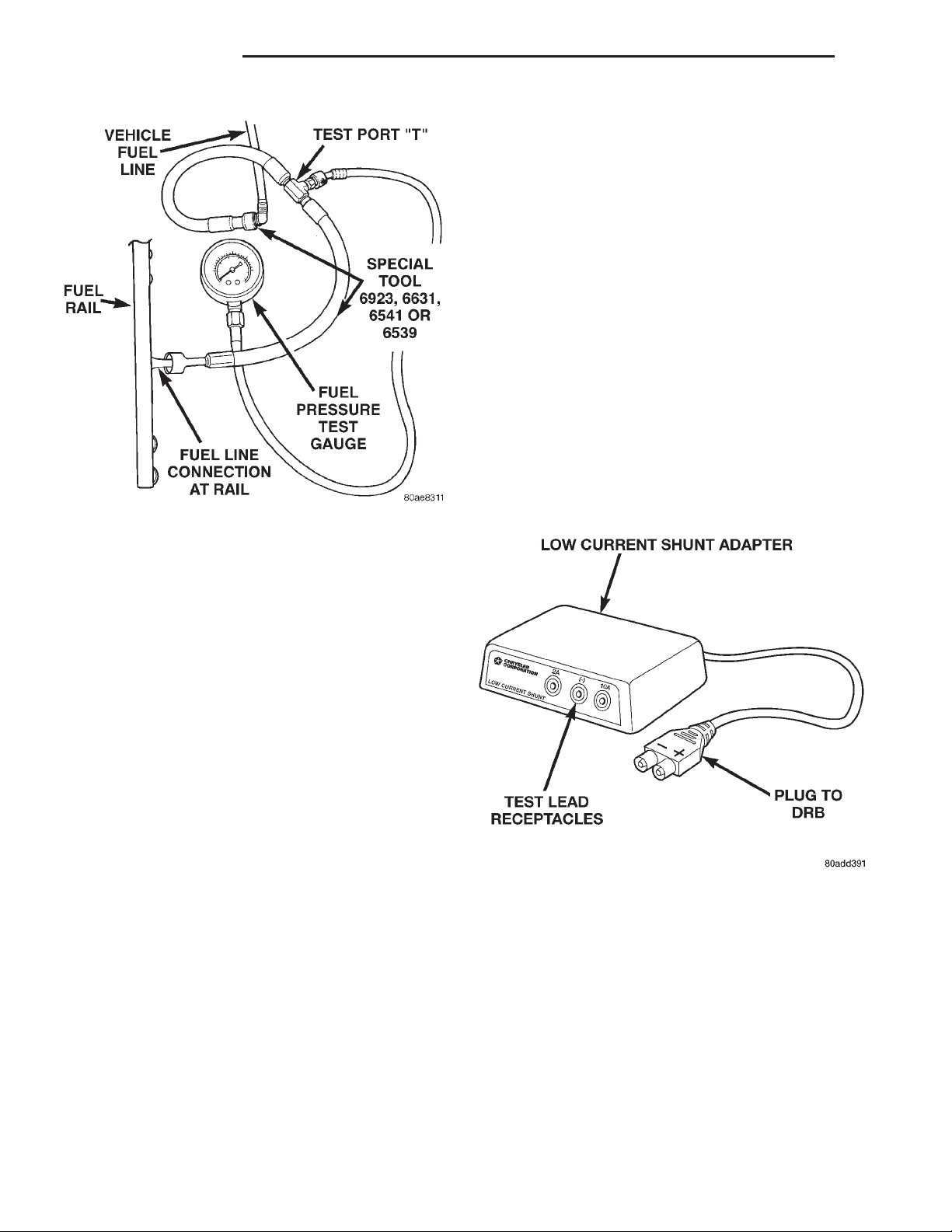
(3) Connect correct Fuel Line Pressure Test
Adapter Tool Hose between disconnected fuel line
and fuel rail (Fig. 8).
Page 8
14 - 8 FUEL SYSTEM XJ
DIAGNOSIS AND TESTING (Continued)
Note: A quick loss of pressure usually indicates a
defective check valve in the filter/regulator. A slow
loss of pressure usually indicates a defective check
valve in the electric fuel pump.
The electric fuel pump is not serviced separately.
Replace the fuel pump module assembly. The filter/
regulator may be replaced separately on certain
applications. Refer to Fuel Filter/Fuel Pressure Regulator Removal/Installation for additional information.
FUEL PUMP AMPERAGE TEST
This amperage (current draw) test is to be done in
conjunction with the Fuel Pump Pressure Test, Fuel
Pump Capacity Test and Fuel Pressure Leak Down
Test. Before performing the amperage test, be sure
the temperature of the fuel tank is above 50° F (10°
C).
The DRB Scan Tool along with the DRB Low Cur-
rent Shunt (LCS) adapter (Fig. 9) and its test leads
will be used to check fuel pump amperage specifications.
Fig. 8 Connecting Adapter Tool—Typical
(4) Connect the 0-414 kPa (0-60 psi) fuel pressure
test gauge (from Gauge Set 5069) to the test port on
the appropriate Adaptor Tool. The fittings on both
tools must be in good condition and free from
any small leaks before performing the proceeding test.
(5) Start engine and bring to normal operating
temperature.
(6) Observe test gauge. Normal operating pressure
should be 339 kPa 6 34 kPa (49.2 psi 6 5 psi).
(7) Shut engine off.
(8) Pressure should not fall below 30 psi for five
minutes.
(9) If pressure falls below 30 psi, it must be determined if a fuel injector, the check valve within the
fuel pump module, or a fuel tube/line is leaking.
(10) Again, start engine and bring to normal operating temperature.
(11) Shut engine off.
(12) Testing for fuel injector or fuel rail leak-
age: Clamp off the rubber hose portion of Adaptor
Tool between the fuel rail and the test port “T” on
Adapter Tool. If pressure now holds at or above 30
psi, a fuel injector or the fuel rail is leaking.
(13) Testing for fuel pump check valve, filter/
regulator check valve or fuel tube/line leakage:
Clamp off the rubber hose portion of Adaptor Tool
between the vehicle fuel line and test port “T” on
Adapter Tool. If pressure now holds at or above 30
psi, a leak may be found at a fuel tube/line. If no
leaks are found at fuel tubes or lines, one of the
check valves in either the electric fuel pump or filter/
regulator may be leaking.
(1) Be sure fuel tank contains fuel before starting
test. If tank is empty or near empty, amperage readings will be incorrect.
(2) Obtain LCS adapter.
(3) Plug cable from LCS adapter into DRB scan
tool at SET 1 receptacle.
(4) Plug DRB into vehicle 16–way connector (data
link connector).
(5) Connect (-) and (+) test cable leads into LCS
adapter receptacles. Use 10 amp (10A +) receptacle
and common (-) receptacles.
Fig. 9 Low Current Shunt Adapter
Page 9
XJ FUEL SYSTEM 14 - 9
DIAGNOSIS AND TESTING (Continued)
(6) Gain access to MAIN MENU on DRB screen.
(7) Press DVOM button on DRB.
(8) Using left/right arrow keys, highlight CHAN-
NEL 1 function on DRB screen.
(9) Press ENTER three times.
(10) Using up/down arrow keys, highlight RANGE
on DRB screen (screen will default to 2 amp scale).
(11) Press ENTER to change 2 amp scale to 10
amp scale. This step must be done to prevent
damage to DRB scan tool or LCS adapter
(blown fuse).
(12) Remove cover from Power Distribution Center
(PDC).
(13) Remove fuel pump relay from PDC. Refer to
label on PDC cover for relay location.
WARNING: BEFORE PROCEEDING TO NEXT STEP,
NOTE THE FUEL PUMP WILL BE ACTIVATED AND
SYSTEM PRESSURE WILL BE PRESENT. THIS WILL
OCCUR AFTER CONNECTING TEST LEADS FROM
LCS ADAPTER INTO FUEL PUMP RELAY CAVITIES.
THE FUEL PUMP WILL OPERATE EVEN WITH IGNITION KEY IN OFF POSITION. BEFORE ATTACHING
TEST LEADS, BE SURE ALL FUEL LINES AND FUEL
SYSTEM COMPONENTS ARE CONNECTED.
CAUTION: TO PREVENT POSSIBLE DAMAGE TO
THE VEHICLE ELECTRICAL SYSTEM AND LCS
ADAPTER, THE TEST LEADS MUST BE CONNECTED INTO RELAY CAVITIES EXACTLY AS
SHOWN IN FOLLOWING STEPS.
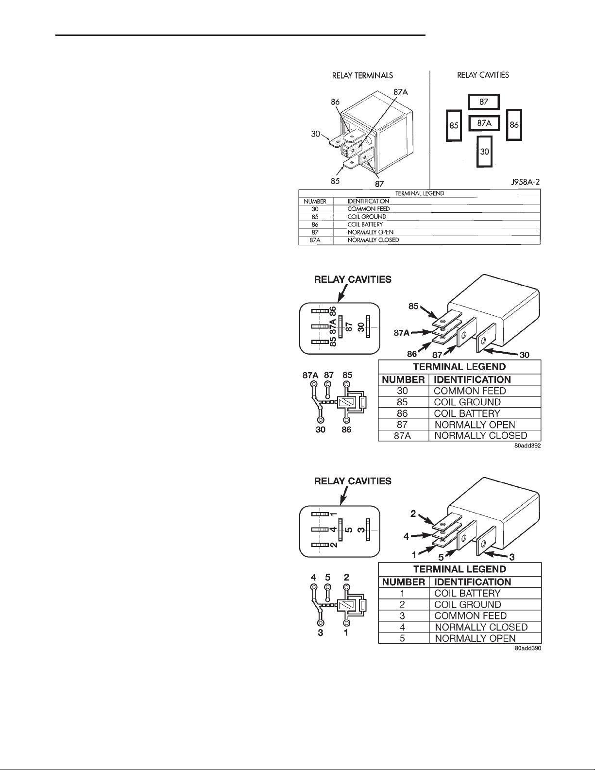
Depending upon vehicle model, year or engine configuration, three different types of relays may be
used: Type-1, type-2 and type–3.
(14) If equipped with type–1 relay (Fig. 10),
attach test leads from LCS adapter into PDC relay
cavities number 30 and 87. For location of these cavities, refer to numbers stamped to bottom of relay
(Fig. 10).
(15) If equipped with type–2 relay (Fig. 11),
attach test leads from LCS adapter into PDC relay
cavities number 30 and 87. For location of these cavities, refer to numbers stamped to bottom of relay
(Fig. 11).
(16) If equipped with type–3 relay (Fig. 12),
attach test leads from LCS adapter into PDC relay
cavities number 3 and 5. For location of these cavities, refer to numbers stamped to bottom of relay
(Fig. 12).
When LCS adapter test leads are attached into
(17)
relay cavities, fuel pump will be activated.
fuel pump amperage on DRB screen. Amperage
should be below 10.0 amps. If amperage is below 10.0
amps, and specifications for the Fuel Pump Pressure,
Determine
Fig. 10 Type–1 Relay
Fig. 11 Type–2 Relay
Fig. 12 Type–3 Relay
Fuel Pump Capacity and Fuel Pressure Leak Down
tests were met, the fuel pump module is OK.
Page 10

14 - 10 FUEL SYSTEM XJ
DIAGNOSIS AND TESTING (Continued)
(18) If amperage is more than 10.0 amps, replace
fuel pump module assembly. The electric fuel pump
is not serviced separately.
(19) Disconnect test leads from relay cavities
immediately after testing.
FUEL GAUGE SENDING UNIT
The fuel gauge sending unit contains a variable
resistor (track). As the float moves up or down, electrical resistance will change. Refer to Instrument
Panel and Gauges for Fuel Gauge testing. To test the
gauge sending unit only, it must be removed from
vehicle. The unit is part of the fuel pump module.
Refer to Fuel Pump Module Removal/Installation for
procedures. Measure the resistance across the sending unit terminals. With float in up position, resistance should be 20 ohms (+/- 5%). With float in down
position, resistance should be 270 ohms (+/- 5%).
FUEL INJECTOR TEST
To perform a complete test of the fuel injectors and
their circuitry, use the DRB scan tool and refer to the
appropriate Powertrain Diagnostics Procedures manual. To test the injector only, refer to the following:
Disconnect the fuel injector wire harness connector
from the injector. The injector is equipped with 2
electrical terminals (pins). Place an ohmmeter across
the terminals. Resistance reading should be approximately 12 ohms 61.2 ohms at 20°C (68°F).
SERVICE PROCEDURES
FUEL SYSTEM PRESSURE RELEASE PROCEDURE
Use following procedure if fuel rail is or is
not equipped with fuel pressure test port.
(1) Remove fuel fill cap.
(2) The fuel filler tube contains a spring-loaded
flap (door) located below fuel fill cap. The flap is used
as a secondary way of sealing fuel tank if fuel fill cap
has not been properly tightened. It is part of EVAP
monitor system when vehicle is equipped with a
Leak Detection Pump (LDP). The vehicle may be
equipped with flap installed into fuel filler tube
even though vehicle is not equipped with LDP
and EVAP monitor system. Place a nonmetallic
object into fuel fill tube and press on flap to relieve
any tank pressure.
(3) Remove Fuel Pump relay from Power Distribution Center (PDC). For location of relay, refer to label
on underside of PDC cover.
(4) Start and run engine until it stalls.
(5) Attempt restarting engine until it will no
longer run.
(6) Turn ignition key to OFF position.
CAUTION: Steps 1, 2, 3 and 4 must be performed to
relieve high pressure fuel from within fuel rail. Do
not attempt to use following steps to relieve this
pressure as excessive fuel will be forced into a cylinder chamber.
(7) Unplug connector from any fuel injector.
(8) Attach one end of a jumper wire with alligator
clips (18 gauge or smaller) to either injector terminal.
(9) Connect other end of jumper wire to positive
side of battery.
(10) Connect one end of a second jumper wire to
remaining injector terminal.
CAUTION: Powering an injector for more than a few
seconds will permanently damage the injector.
(11) Momentarily touch other end of jumper wire
to negative terminal of battery for no more than a
few seconds.
(12) Place a rag or towel below fuel line quick-connect fitting at fuel rail.
(13) Disconnect quick-connect fitting at fuel rail.
Refer to Quick-Connect Fittings.
(14) Return fuel pump relay to PDC.
(15) One or more Diagnostic Trouble Codes (DTC’s)
may have been stored in PCM memory due to fuel
pump relay removal. The DRB scan tool must be
used to erase a DTC.
FUEL TUBES/LINES/HOSES AND CLAMPS
OPERATION
Also refer to Quick-Connect Fittings.
WARNING: THE FUEL SYSTEM IS UNDER A CONSTANT PRESSURE (EVEN WITH THE ENGINE OFF).
BEFORE SERVICING ANY FUEL SYSTEM HOSES,
FITTINGS OR LINES, THE FUEL SYSTEM PRESSURE MUST BE RELEASED. REFER TO THE FUEL
SYSTEM PRESSURE RELEASE PROCEDURE IN
THIS GROUP.
Inspect all hose connections such as clamps, couplings and fittings to make sure they are secure and
leaks are not present. The component should be
replaced immediately if there is any evidence of degradation that could result in failure.
Never attempt to repair a plastic fuel line/tube.
Replace as necessary.
Avoid contact of any fuel tubes/hoses with other
vehicle components that could cause abrasions or
scuffing. Be sure that the plastic fuel lines/tubes are
properly routed to prevent pinching and to avoid heat
sources.
The lines/tubes/hoses used on fuel injected vehicles
are of a special construction. This is due to the
Page 11
XJ FUEL SYSTEM 14 - 11
SERVICE PROCEDURES (Continued)
higher fuel pressures and the possibility of contaminated fuel in this system. If it is necessary to replace
these lines/tubes/hoses, only those marked EFM/EFI
may be used.
If equipped: The hose clamps used to secure rubber hoses on fuel injected vehicles are of a special
rolled edge construction. This construction is used to
prevent the edge of the clamp from cutting into the
hose. Only these rolled edge type clamps may be
used in this system. All other types of clamps may
cut into the hoses and cause high-pressure fuel leaks.
Use new original equipment type hose clamps.
Tighten hose clamps to 3 N·m (25 in. lbs.) torque.
QUICK-CONNECT FITTINGS
Also refer to Fuel Tubes/Lines/Hoses and Clamps.
Different types of quick-connect fittings are used to
attach various fuel system components, lines and
tubes. These are: a single-tab type, a two-tab type or
a plastic retainer ring type. Safety latch clips are
used on certain components/lines. Certain fittings
may require use of a special tool for disconnection.
DISCONNECTING
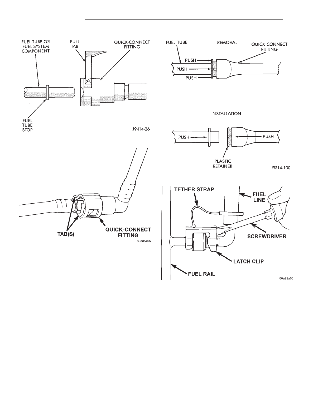
(5) Two-Tab Type Fitting: This type of fitting is
equipped with tabs located on both sides of fitting
(Fig. 16). The tabs are supplied for disconnecting
quick-connect fitting from component being serviced.
Fig. 13 Single-Tab Type Fitting
WARNING: THE FUEL SYSTEM IS UNDER A CONSTANT PRESSURE (EVEN WITH ENGINE OFF).
BEFORE SERVICING ANY FUEL SYSTEM HOSE,
FITTING OR LINE, FUEL SYSTEM PRESSURE MUST
BE RELEASED. REFER TO FUEL SYSTEM PRESSURE RELEASE PROCEDURE.
CAUTION: The interior components (o-rings, spacers) of some types of quick-connect fitting are not
serviced separately. If service parts are not available, do not attempt to repair a damaged fitting or
fuel line. If repair is necessary, replace complete
fuel line assembly.
(1) Perform fuel pressure release procedure. Refer
to Fuel Pressure Release Procedure in this group.
(2) Disconnect negative battery cable from battery.
(3) Clean fitting of any foreign material before dis-
assembly.
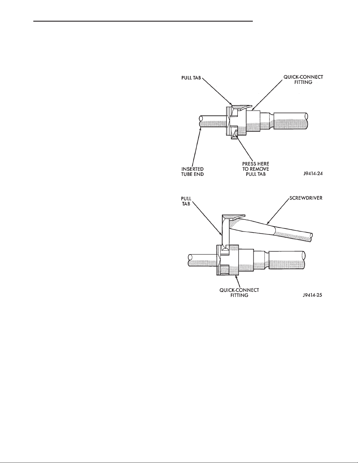
(4) Single-Tab Type Fitting: This type of fitting
is equipped with a single pull tab (Fig. 13). The tab
is removable. After tab is removed, quick-connect fitting can be separated from fuel system component.
(a) Press release tab on side of fitting to release
pull tab (Fig. 14). If release tab is not pressed
prior to releasing pull tab, pull tab will be
damaged.
(b) While pressing release tab on side of fitting,
use screwdriver to pry up pull tab (Fig. 14).
(c) Raise pull tab until it separates from quick-
connect fitting (Fig. 15).
Fig. 14 Disconnecting Single-Tab Type Fitting
(a) To disconnect quick-connect fitting, squeeze
plastic retainer tabs (Fig. 16) against sides of
quick-connect fitting with your fingers. Tool use is
not required for removal and may damage plastic
retainer.
(b) Pull fitting from fuel system component
being serviced.
(c) The plastic retainer will remain on component being serviced after fitting is disconnected.
The o-rings and spacer will remain in quick-connect fitting connector body.
(6) Plastic Retainer Ring Type Fitting: This
type of fitting can be identified by the use of a fullround plastic retainer ring (Fig. 17) usually black in
color.
(a) To release fuel system component from quickconnect fitting, firmly push fitting towards compo-
Page 12
14 - 12 FUEL SYSTEM XJ
SERVICE PROCEDURES (Continued)
Fig. 15 Removing Pull Tab
Fig. 16 Typical Two-Tab Type Quick-Connect Fitting
nent being serviced while firmly pushing plastic
retainer ring into fitting (Fig. 17). With plastic ring
depressed, pull fitting from component. The plas-
tic retainer ring must be pressed squarely
into fitting body. If this retainer is cocked
during removal, it may be difficult to disconnect fitting. Use an open-end wrench on
shoulder of plastic retainer ring to aid in disconnection.
(b) After disconnection, plastic retainer ring will
remain with quick-connect fitting connector body.
(c) Inspect fitting connector body, plastic retainer
ring and fuel system component for damage.
Replace as necessary.
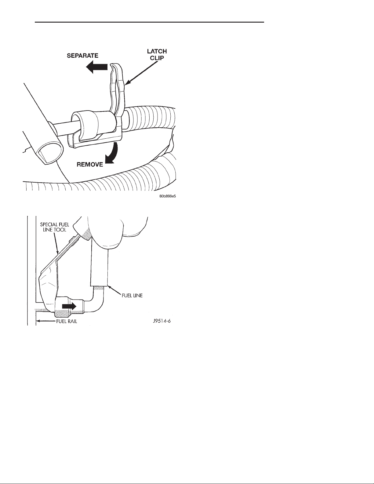
(7) Latch Clips: Depending on vehicle model and
engine, 2 different types of safety latch clips are used
(Fig. 18) or (Fig. 19). Type-1 is tethered to fuel line
and type-2 is not. A special tool will be necessary to
disconnect fuel line after latch clip is removed. The
latch clip may be used on certain fuel line/fuel rail
connection, or to join fuel lines together.
Fig. 17 Plastic Retainer Ring Type Fitting
Fig. 18 Latch Clip—Type 1
(a) Type 1: Pry up on latch clip with a screw-
driver (Fig. 18).
(b) Type 2: Separate and unlatch 2 small arms
on end of clip (Fig. 19) and swing away from fuel
line.
(c) Slide latch clip toward fuel rail while lifting
with screwdriver.
(d) Insert special fuel line removal tool (Snap-On
number FIH 9055-1 or equivalent) into fuel line
(Fig. 20). Use tool to release locking fingers in end
of line.
(e) With special tool still inserted, pull fuel line
from fuel rail.
Page 13
XJ FUEL SYSTEM 14 - 13
SERVICE PROCEDURES (Continued)
(4) Continue pushing until a click is felt.
(5) Single-tab type fitting: Push new tab down
until it locks into place in quick-connect fitting.
(6) Verify a locked condition by firmly pulling on
fuel tube and fitting (15-30 lbs.).
(7) Latch Clip Equipped: Install latch clip (snaps
into position). If latch clip will not fit, this indi-
cates fuel line is not properly installed to fuel
rail (or other fuel line). Recheck fuel line connection.
(8) Connect negative cable to battery.
(9) Start engine and check for leaks.
REMOVAL AND INSTALLATION
FUEL FILTER/FUEL PRESSURE REGULATOR
The combination Fuel Filter/Fuel Pressure Regula-
tor is located on the fuel pump module. The fuel
pump module is located on top of fuel tank.
The filter/regulator may be removed without
removing fuel pump module although fuel tank must
Fig. 19 Latch Clip—Type 2
be removed.
Fig. 20 Fuel Line Disconnection Using Special Tool
(f) After disconnection, locking fingers will
remain within quick-connect fitting at end of fuel
line.
(8) Disconnect quick-connect fitting from fuel sys-
tem component being serviced.
CONNECTING
(1) Inspect quick-connect fitting body and fuel sys-
tem component for damage. Replace as necessary.
(2) Prior to connecting quick-connect fitting to
component being serviced, check condition of fitting
and component. Clean parts with a lint-free cloth.
Lubricate with clean engine oil.
(3) Insert quick-connect fitting into fuel tube or
fuel system component until built-on stop on fuel
tube or component rests against back of fitting.
REMOVAL
(1) Remove fuel tank. Refer to Fuel Tank Removal/
Installation.
(2) Clean area around filter/regulator.
(3) Disconnect fuel line at filter/regulator. Refer to
Quick-Connect Fittings in this group for procedures.
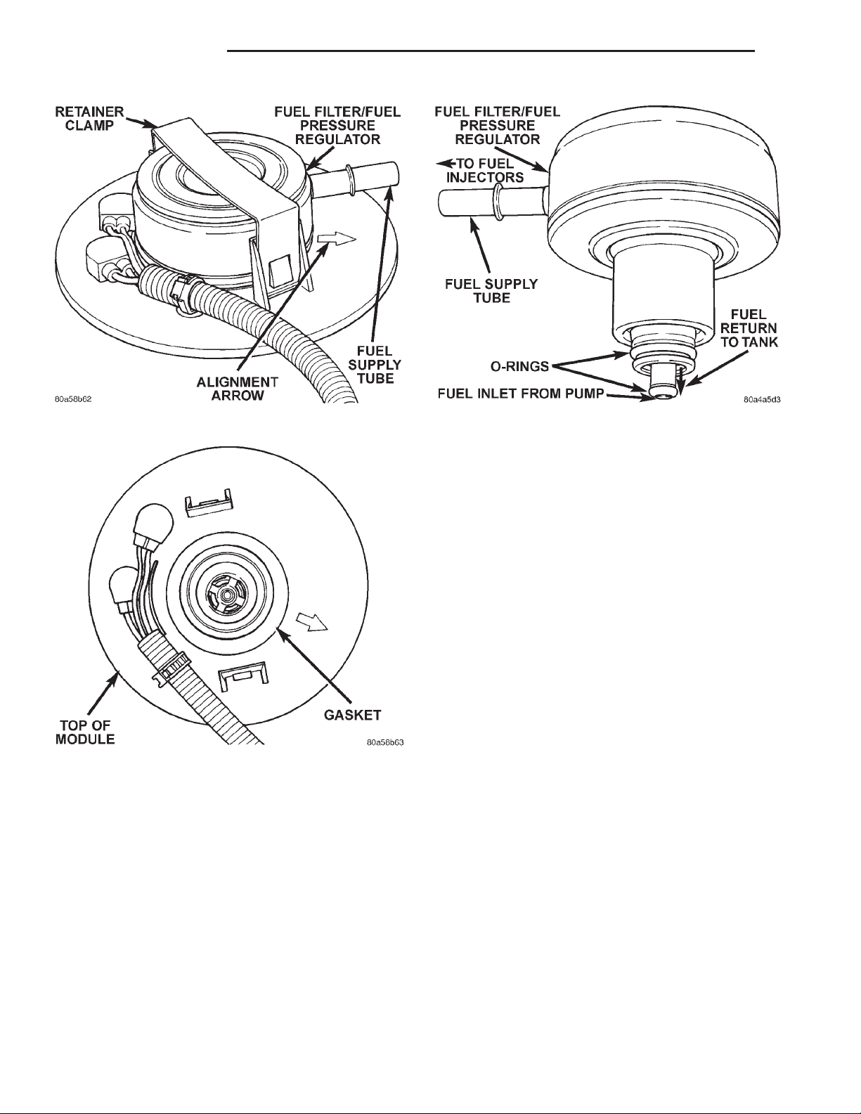
(4) Remove retainer clamp from top of filter/regulator (Fig. 21). Clamp snaps to tabs on pump module.
Discard old clamp.
(5) Pry filter/regulator from top of pump module
with 2 screwdrivers. Unit is snapped into module.
(6) Discard gasket below filter/regulator (Fig. 22).
(7) Before discarding filter/regulator assembly,
inspect assembly to verify that o-rings (Fig. 23) are
intact. If the smallest of the two o-rings can not be
found on bottom of filter/regulator, it may be necessary to remove it from the fuel inlet passage in fuel
pump module.
INSTALLATION
(1) Clean recessed area in pump module where filter/regulator is to be installed.
(2) Obtain new filter/regulator (two new o-rings
should already be installed) .
(3) Apply a small amount of clean engine oil to
o-rings. Do not install o-rings separately into
fuel pump module. They will be damaged when
installing filter/regulator.
(4) Install new gasket to top of fuel pump module.
(5) Press new filter/regulator into top of pump
module until it snaps into position (a positive click
must be heard or felt).
Page 14
14 - 14 FUEL SYSTEM XJ
REMOVAL AND INSTALLATION (Continued)
Fig. 21 Fuel Filter/Fuel Pressure Regulator
Fig. 22 Fuel Filter/Fuel Pressure Regulator Gasket
(6) The arrow (Fig. 21) molded into top of fuel
pump module should be pointed towards front of
vehicle (12 o’clock position).
(7) Rotate filter/regulator until fuel supply tube
(fitting) is pointed towards front of vehicle (12 o’clock
position).
(8) Install new retainer clamp (clamp snaps over
top of filter/regulator and locks to flanges on pump
module).
(9) Connect fuel line at filter/regulator. Refer to
Quick-Connect Fittings in this group for procedures.
(10) Install fuel tank. Refer to Fuel Tank Removal/
Installation.
Fig. 23 Fuel Filter/Fuel Pressure Regulator O-Rings
FUEL PUMP MODULE
Fuel tank removal will be necessary for fuel pump
module removal.
REMOVAL
WARNING: THE FUEL SYSTEM IS UNDER A CONSTANT PRESSURE EVEN WITH ENGINE OFF.
BEFORE SERVICING THE FUEL PUMP MODULE,
FUEL SYSTEM PRESSURE MUST BE RELEASED.
(1) Drain fuel tank and remove tank. Refer to the
Fuel Tank Removal/Installation section of this group.
(2) Thoroughly wash and clean area around pump
module to prevent contaminants from entering tank.
(3) Disconnect fuel line at filter/regulator. Refer to
Quick-Connect Fittings in this group for procedures.
(4) The plastic fuel pump module locknut is
threaded onto fuel tank (Fig. 24). Install Special Tool
6856 to fuel pump module locknut and remove locknut (Fig. 25). The fuel pump module will spring up
when locknut is removed.
(5) Remove module from fuel tank.
INSTALLATION
CAUTION: Whenever fuel pump module is serviced,
module gasket must be replaced.
(1) Thoroughly clean locknut threads and mating
fuel tank threads. Use a soap/water solution. Do not
use carburetor cleaner to clean threads.
(2) Using a new gasket, position gasket and fuel
pump module into opening in fuel tank.
(3) Apply clean water to gasket and locknut
threads.
Page 15
XJ FUEL SYSTEM 14 - 15
REMOVAL AND INSTALLATION (Continued)
FUEL PUMP INLET FILTER
The fuel pump inlet filter (strainer) is located on
the bottom of fuel pump module (Fig. 26). The fuel
pump module is located on top of fuel tank.
Fig. 24 Top View of Fuel Tank and Fuel Pump
Module
Fig. 25 Locknut Removal/Installation—Typical
(4) Position locknut over top of fuel pump module.
(5) Rotate module until molded arrow (Fig. 24) is
pointed toward front of vehicle (12 o’clock position).
This step must be done to prevent float/float rod
assembly from contacting sides of fuel tank.
(6) Install Special Tool 6856 to locknut.
(7) Tighten locknut to 74 N·m (55 ft. lbs.) torque.
(8) Rotate fuel filter/fuel pressure regulator until
its fitting is pointed toward front of vehicle (12
o’clock position).
(9) Connect fuel line at filter/regulator. Refer to
Quick-Connect Fittings in this group for procedures.
(10) Install fuel tank. Refer to Fuel Tank Installation in this section.
Fig. 26 Fuel Pump Inlet Filter
REMOVAL
(1) Remove fuel tank. Refer to Fuel Tank Removal/
Installation.
(2) Remove fuel pump module. Refer to Fuel Pump
Module Removal/Installation.
(3) Remove filter by prying from bottom of module
with 2 screwdrivers. Filter is snapped to module.
(4) Clean bottom of pump module.
INSTALLATION
(1) Snap new filter to bottom of module.
(2) Install fuel pump module. Refer to Fuel Pump
Module Removal/Installation.
(3) Install fuel tank. Refer to Fuel Tank Removal/
Installation.
FUEL GAUGE SENDING UNIT
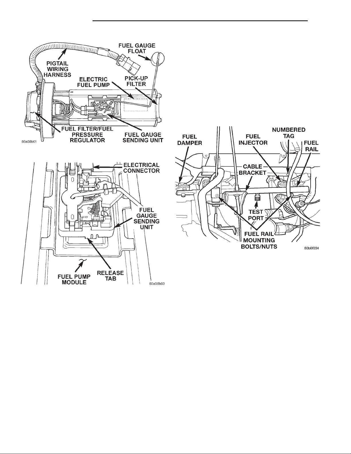
The fuel gauge sending unit (fuel level sensor) and
float assembly is located on the side of fuel pump
module (Fig. 27). The fuel pump module is located
within the fuel tank.
REMOVAL
(1) Remove fuel tank. Refer to Fuel Tank Removal/
Installation.
(2) Remove fuel pump module. Refer to Fuel Pump
Module Removal/Installation.
(3) Remove electrical wire connector at sending
unit terminals.
(4) Press on release tab (Fig. 28) to remove sending unit from pump module.
Page 16
14 - 16 FUEL SYSTEM XJ
REMOVAL AND INSTALLATION (Continued)
(1) Remove fuel tank filler tube cap.
(2) Perform Fuel System Pressure Release Procedure as described in this Group.
(3) Disconnect negative battery cable from battery.
(4) Remove air tube at top of throttle body. Note:
Some engine/vehicles may require removal of air
cleaner ducts at throttle body.
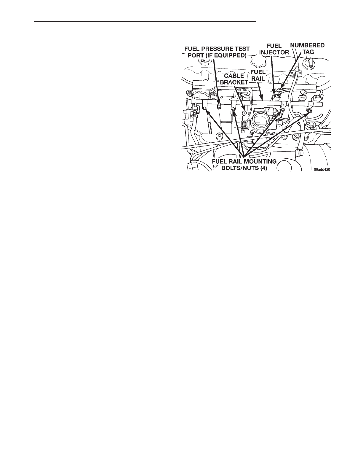
(5) Remove injector harness electrical connectors
at each injector. Each injector connector should have
a numerical tag attached identifying its corresponding cylinder (Fig. 29). If not, identify each connector
before removal.
Fig. 27 Fuel Gauge Sending Unit Location
Fig. 28 Fuel Gauge Sending Unit Release Tab
INSTALLATION
(1) Position sending unit to pump module and
snap into place.
(2) Connect electrical connector to terminals.
(3) Install fuel pump module. Refer to Fuel Pump
Module Removal/Installation.
(4) Install fuel tank. Refer to Fuel Tank Removal/
Installation.
FUEL INJECTOR RAIL—2.5L ENGINE
REMOVAL
WARNING: THE FUEL SYSTEM IS UNDER CONSTANT FUEL PRESSURE EVEN WITH ENGINE OFF.
THIS PRESSURE MUST BE RELEASED BEFORE
SERVICING FUEL RAIL.
Fig. 29 Fuel Rail Mounting—2.5L Engine
(6) Disconnect fuel supply line latch clip and fuel
line at fuel rail. Refer to Quick-Connect Fittings in
this group for procedures.
(7) Disconnect throttle cable at throttle body. Refer
to Throttle Cable Removal/Installation in this group
for procedures.
(8) Disconnect speed control cable at throttle body
(if equipped). Refer to Speed Control Cable in Group
8H, Speed Control System for procedures.
(9) Disconnect automatic transmission cable at
throttle body (if equipped).
(10) Remove cable routing bracket (Fig. 29) at
intake manifold.
(11) Remove nut securing crankshaft position sensor pigtail harness to fuel rail mounting stud.
Remove clamp and harness from fuel rail mounting
stud.
(12) Clean dirt/debris from each fuel injector at
intake manifold.
(13) Remove fuel rail mounting nuts/bolts (Fig.
29).
(14) Remove fuel rail by gently rocking until all
the fuel injectors are out of intake manifold.
Page 17
XJ FUEL SYSTEM 14 - 17
REMOVAL AND INSTALLATION (Continued)
INSTALLATION
(1) Clean each injector bore at intake manifold.
(2) Apply a small amount of clean engine oil to
each injector o-ring. This will aid in installation.
(3) Position tips of all fuel injectors into the corresponding injector bore in intake manifold. Seat injectors into manifold.
(4) Install and tighten fuel rail mounting bolts to
11 63 N·m (100 625 in. lbs.) torque.
(5) Position crankshaft position sensor pigtail wire
harness clamp and wire harness to fuel rail mounting stud. Install nut securing harness to fuel rail
mounting stud.
(6) Connect tagged injector harness connectors to
appropriate injector.
(7) Connect fuel line and fuel line latch clip to fuel
rail. Refer Quick-Connect Fittings in this group for
procedures.
(8) Install protective cap to pressure test port fitting (if equipped).
(9) Install cable routing bracket to intake manifold.
(10) Connect throttle cable at throttle body.
(11) Connect speed control cable at throttle body (if
equipped).
(12) Connect automatic transmission cable at
throttle body (if equipped).
(13) Install air tube (or duct) at top of throttle
body.
(14) Install fuel tank cap.
(15) Connect negative battery cable to battery.
(16) Start engine and check for fuel leaks.
FUEL INJECTOR RAIL—4.0L ENGINE
REMOVAL
WARNING: THE FUEL SYSTEM IS UNDER CONSTANT FUEL PRESSURE EVEN WITH ENGINE OFF.
THIS PRESSURE MUST BE RELEASED BEFORE
SERVICING FUEL RAIL.
(1) Remove fuel tank filler tube cap.
(2) Perform Fuel System Pressure Release Procedure as described in this Group.
(3) Disconnect negative battery cable from battery.
(4) Remove air tube at top of throttle body. Note:
Some engine/vehicles may require removal of air
cleaner ducts at throttle body.
(5) Remove injector harness electrical connectors
at each injector. Each injector connector should have
a numerical tag attached identifying its corresponding cylinder (Fig. 30). If not, identify each connector
before removal.
Fig. 30 Fuel Rail Mounting—4.0L Engine
(6) Disconnect fuel supply line latch clip and fuel
line at fuel rail. Refer to Quick-Connect Fittings in
this group for procedures.
(7) Disconnect throttle cable at throttle body. Refer
to Throttle Cable Removal/Installation in this group
for procedures.
(8) Disconnect speed control cable at throttle body
(if equipped). Refer to Speed Control Cable in Group
8H, Speed Control System for procedures.
(9) Disconnect automatic transmission cable at
throttle body (if equipped).
(10) Remove cable routing bracket (Fig. 30) at
intake manifold.
(11) Remove nut securing crankshaft position sensor pigtail harness to fuel rail mounting stud.
Remove clamp and harness from fuel rail mounting
stud.
(12) Clean dirt/debris from each fuel injector at
intake manifold.
(13) Remove fuel rail mounting nuts/bolts (Fig.
30).
(14) Remove fuel rail by gently rocking until all
the fuel injectors are out of intake manifold.
INSTALLATION
(1) Clean each injector bore at intake manifold.
(2) Apply a small amount of clean engine oil to
each injector o-ring. This will aid in installation.
(3) Position tips of all fuel injectors into the corresponding injector bore in intake manifold. Seat injectors into manifold.
(4) Install and tighten fuel rail mounting bolts to
11 63 N·m (100 625 in. lbs.) torque.
(5) Position crankshaft position sensor pigtail wire
harness clamp and wire harness to fuel rail mount-
Page 18
14 - 18 FUEL SYSTEM XJ
REMOVAL AND INSTALLATION (Continued)
ing stud. Install nut securing harness to fuel rail
mounting stud.
(6) Connect tagged injector harness connectors to
appropriate injector.
(7) Connect fuel line and fuel line latch clip to fuel
rail. Refer Quick-Connect Fittings in this group for
procedures.
(8) Install protective cap to pressure test port fitting (if equipped).
(9) Install cable routing bracket to intake manifold.
(10) Connect throttle cable at throttle body.
(11) Connect speed control cable at throttle body (if
equipped).
(12) Connect automatic transmission cable at
throttle body (if equipped).
(13) Install air tube (or duct) at top of throttle
body.
(14) Install fuel tank cap.
(15) Connect negative battery cable to battery.
(16) Start engine and check for fuel leaks.
FUEL INJECTORS
REMOVAL
(1) Remove fuel rail. Refer to Fuel Injector Rail
Removal in this section.
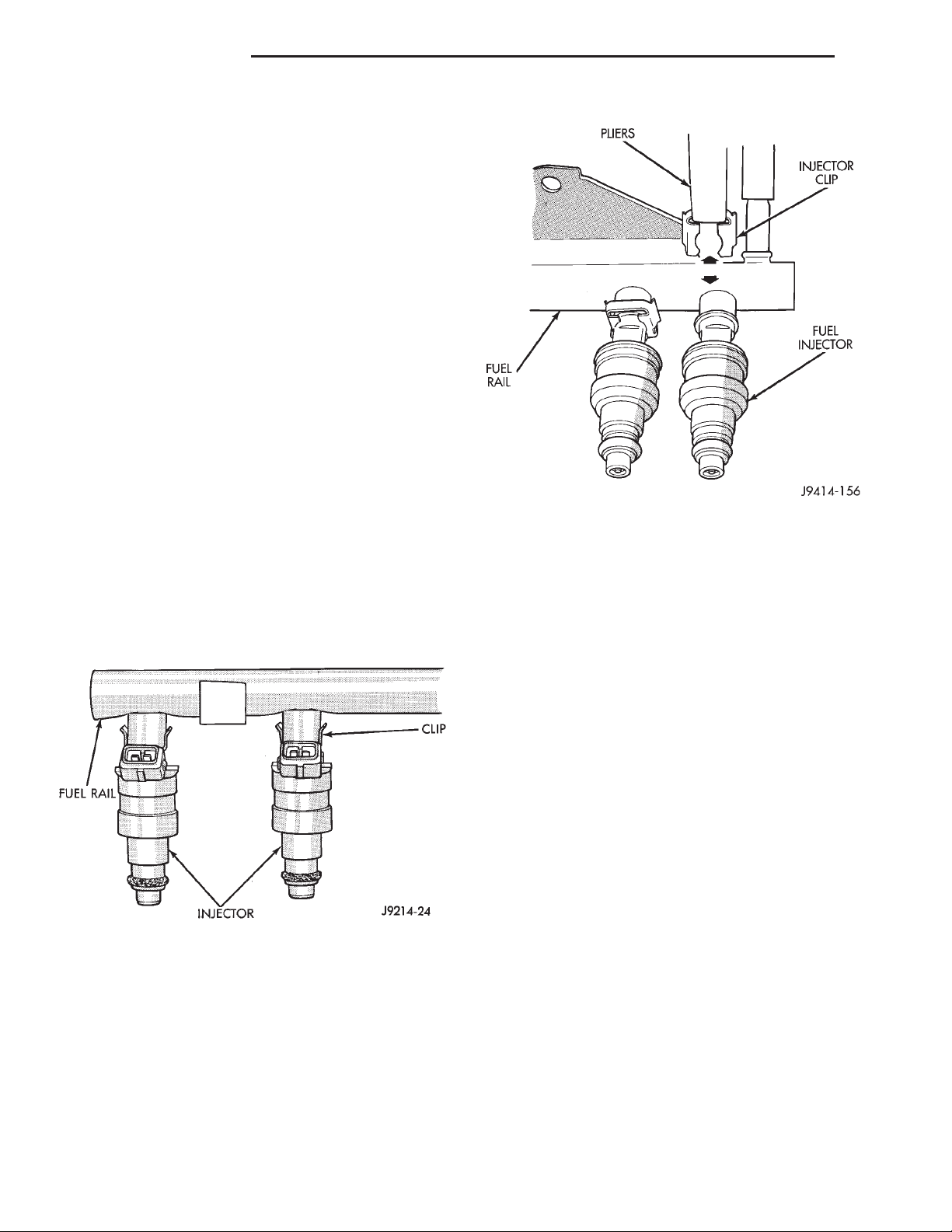
(2) Remove clip(s) that retain fuel injector(s) to
fuel rail (Fig. 31) or (Fig. 32).
Fig. 31 Injector Mounting
INSTALLATION
(1) Install fuel injector(s) into fuel rail assembly
and install retaining clip(s).
(2) If same injector(s) is being reinstalled, install
new o-ring(s).
(3) Apply a small amount of clean engine oil to
each injector o-ring. This will aid in installation.
(4) Install fuel rail. Refer to Fuel Rail Installation
in this section.
(5) Start engine and check for fuel leaks.
Fig. 32 Injector Retaining Clips—Typical Injector
FUEL TANK
WARNING: THE FUEL SYSTEM IS UNDER CONSTANT FUEL PRESSURE EVEN WITH THE ENGINE
OFF. THIS PRESSURE MUST BE RELEASED
BEFORE SERVICING FUEL TANK.
Two different procedures may be used to drain fuel
tank (lowering tank or using DRB scan tool).
The quickest draining procedure involves lowering
the fuel tank.
As an alternative procedure, the electric fuel pump
may be activated allowing tank to be drained at fuel
rail connection. Refer to DRB scan tool for fuel pump
activation procedures. Before disconnecting fuel line
at fuel rail, release fuel pressure. Refer to the Fuel
System Pressure Release Procedure in this group for
procedures. Attach end of special test hose tool number 6541, 6539, 6631 or 6923 at fuel rail disconnection (tool number will depend on model and/or engine
application). Position opposite end of this hose tool to
an approved gasoline draining station. Activate fuel
pump and drain tank until empty.
If electric fuel pump is not operating, tank must be
lowered for fuel draining. Refer to following procedures.
REMOVAL
(1) Disconnect negative battery cable at battery.
(2) Release fuel system pressure. Refer to the Fuel
System Pressure Release Procedure in this group.
(3) Raise and support vehicle.
Page 19
XJ FUEL SYSTEM 14 - 19
REMOVAL AND INSTALLATION (Continued)
(4) If Equipped: Remove fuel tank skid plate. Refer
to Group 23, Body for procedures.
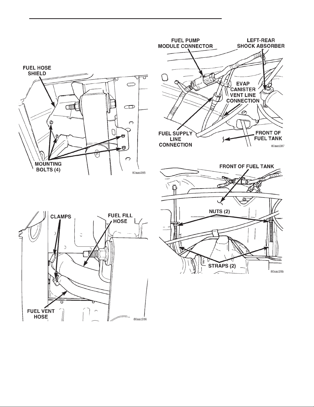
(5) Remove 4 fuel hose shield mounting bolts and
remove fuel hose shield (Fig. 33) from body.
Fig. 35 Fuel Tank Connections at Front of Fuel Tank
Fig. 33 Fuel Hose Shield
(6) Remove fuel tank fill hose and vent hose
clamps at fuel tank filler tube (Fig. 34). Remove both
hoses at fuel filler tube (Fig. 34).
Fig. 34 Fuel Fill and Vent Hoses
(7) Remove exhaust tailpipe heat shield mounting
bolts and remove shield.
CAUTION: To protect fuel tank from exhaust heat,
this shield must reinstalled after tank installation.
(8) Place a hydraulic jack to bottom of fuel tank.
Fig. 36 Fuel Tank Mounting Straps/Nuts
WARNING: PLACE A SHOP TOWEL AROUND FUEL
LINES TO CATCH ANY EXCESS FUEL.
(9) Disconnect fuel supply line from fuel extension
line near front of fuel tank (Fig. 35). Refer to Fuel
Tubes/Lines/Hoses and Clamps in this group. Also
refer to Quick-Connect Fittings for procedures.
(10) Disconnect EVAP canister vent line near front
of tank (Fig. 35).
(11) Disconnect fuel pump module electrical connector (pigtail harness) near front of tank (Fig. 35).
Harness connector is clipped to body.
(12) Remove two fuel tank strap nuts (Fig. 36).
Position both tank support straps away from tank.
(13) Carefully lower right side of tank while feeding both fuel hoses through access hole in body. Fuel
Page 20
14 - 20 FUEL SYSTEM XJ
REMOVAL AND INSTALLATION (Continued)
(9) Position fuel hose shield to body. Install and
tighten 4 mounting bolts.
(10) Connect fuel pump module pigtail harness
electrical connector near front of tank.
(11) Connect fuel pump module supply line near
front of tank. Refer to Quick-Connect Fittings for
procedures.
(12) Connect EVAP hose near front of tank.
(13) Install exhaust tailpipe heat shield.
(14) Install fuel tank skid plate (if equipped).
(15) Lower vehicle and connect battery cable to
battery.
FUEL TANK FILLER TUBE CAP
If replacement of the fuel tank filler tube cap is
necessary, it must be replaced with an identical cap
to be sure of correct system operation.
CAUTION: Remove the fuel tank filler tube cap to
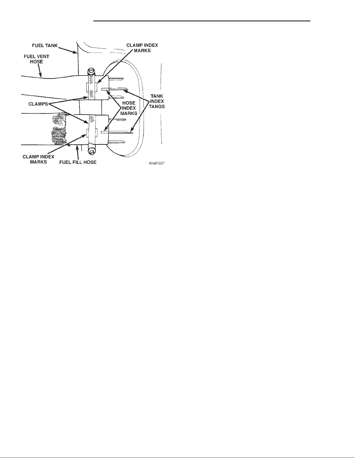
Fig. 37 Fuel Fill/Vent Hose Index Marks
Tank Full And Not Drained Using DRB Scan
Tool: To prevent fuel loss through hoses, keep left
side of tank higher than right side while lowering.
Do not allow hose openings to drop lower than top of
tank.
(14) Continue lowering tank until clear of vehicle.
Place tank on floor with left side (hose side) higher
than right side.
(15) Drain tank by removing fuel fill hose at tank.
Fuel fill hose is largest of 2 hoses (Fig. 37). Insert the
drain hose (from an approved gasoline draining station) into hose opening. Drain tank until empty.
(16) If fuel pump module removal is necessary,
refer to Fuel Pump Module Removal/Installation in
this group for procedures.
relieve fuel tank pressure. The cap must be
removed prior to disconnecting any fuel system
component or before draining the fuel tank.
ACCELERATOR PEDAL
The accelerator pedal is connected to the throttle
body linkage by the throttle cable. The cable is protected by a plastic sheathing and is connected to the
throttle body linkage by a ball socket. It is connected
to the upper part of the accelerator pedal arm by a
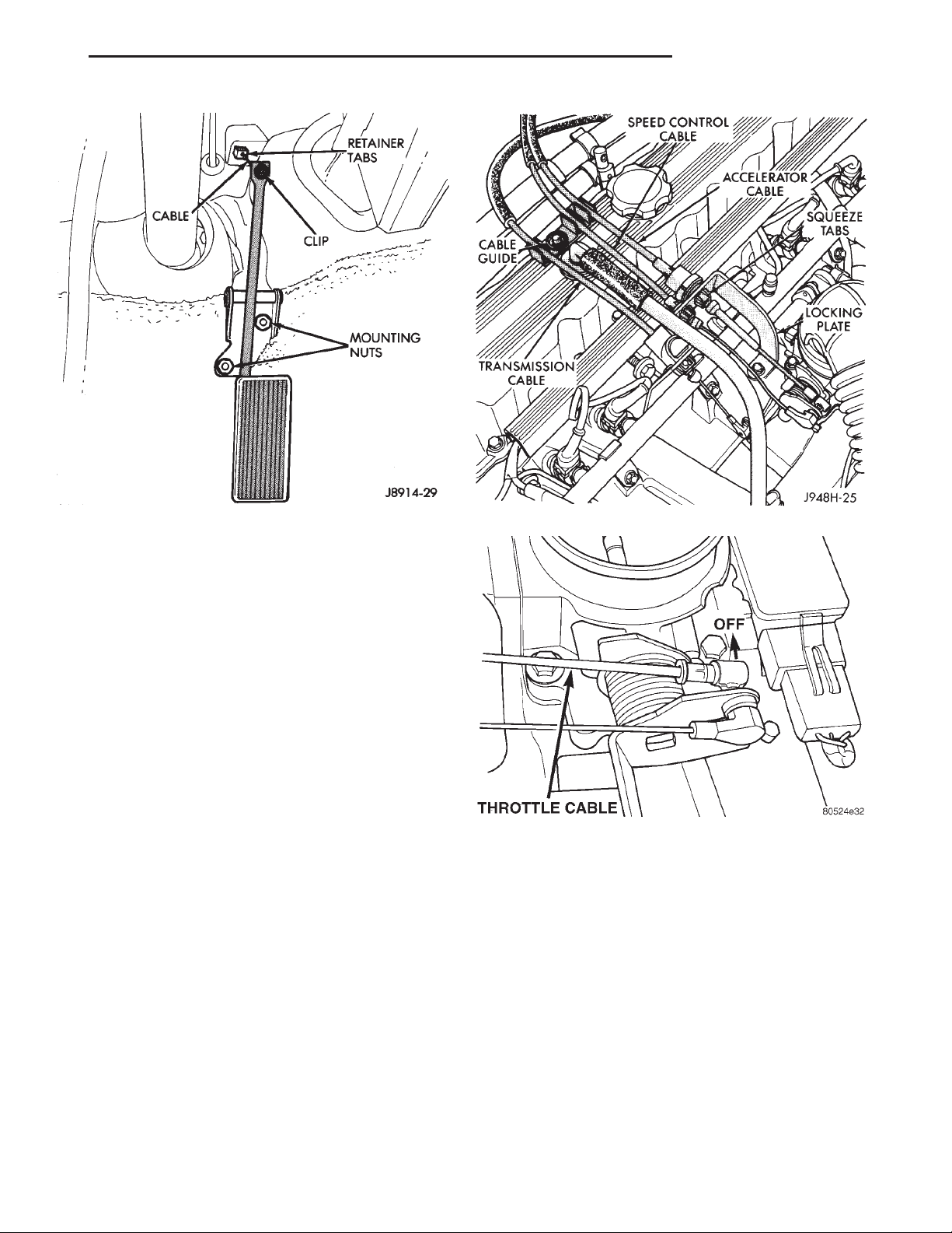
plastic retainer (clip) (Fig. 38). This retainer (clip)
snaps into the top of the accelerator pedal arm.
Retainer tabs (built into the cable sheathing) (Fig.
38) fasten the cable to the dash panel.
Dual throttle return springs (attached to the throttle shaft) are used to close the throttle.
INSTALLATION
(1) If fuel pump module is being installed, refer to
Fuel Pump Module Removal/Installation in this
group for procedures.
(2) Install fuel fill/vent hoses to tank fittings. To
prevent hose from kinking, rotate each hose until
index mark on hose is aligned to index tang on fuel
tank (Fig. 37).
(3) Install hose clamps to hoses. Position clamps
between index marks on each hose (Fig. 37).
(4) Position fuel tank to hydraulic jack.
(5) Raise tank into position while guiding fuel fill
and vent hoses into and through access hole in body.
(6) Continue raising tank until positioned to body.
(7) Attach two fuel tank mounting straps and
mounting nuts. Tighten nuts to 10 N·m (90 in. lbs.)
torque. Do not over tighten nuts.
(8) Install both fuel hoses to fuel fill tube. Tighten
both retaining clamps.
CAUTION: Never attempt to remove or alter these
springs.
CAUTION: Be careful not to damage or kink the
cable core wire (within the cable sheathing) while
servicing the accelerator pedal or throttle cable.
REMOVAL
(1) From inside the vehicle, hold up accelerator
pedal. Remove plastic cable retainer (clip) and throttle cable core wire from upper end of accelerator
pedal arm (Fig. 38). Plastic cable retainer (clip) snaps
into pedal arm.
(2) Remove accelerator pedal mounting bracket
nuts. Remove accelerator pedal assembly.
Page 21
XJ FUEL SYSTEM 14 - 21
REMOVAL AND INSTALLATION (Continued)
Fig. 38 Accelerator Pedal Mounting—Typical
INSTALLATION
(1) Place accelerator pedal assembly over studs
protruding from floor pan. Tighten mounting nuts to
5 N·m (36 in. lbs.) torque.
(2) Slide throttle cable into opening in top of pedal
arm. Push plastic cable retainer (clip) into accelerator pedal arm opening until it snaps into place.
(3) Before starting engine, operate accelerator
pedal to check for any binding.
THROTTLE CABLE
REMOVAL
(1) From inside vehicle, hold up accelerator pedal.
Remove plastic cable retainer (clip) and throttle cable
core wire from upper end of accelerator pedal arm
(Fig. 38). Plastic cable retainer (clip) snaps into pedal
arm.
(2) Remove cable core wire at pedal arm.
(3) From inside vehicle, pinch both sides of cable
housing retainer tabs (Fig. 38) at dash panel.
Remove cable housing from dash panel and pull into
engine compartment.
(4) Remove cable from cable guide on engine cylinder head (valve) cover (Fig. 39).
(5) Remove throttle cable ball end socket at throttle body linkage (snaps off) (Fig. 40).
(6) Remove throttle cable from throttle body
mounting bracket by compressing squeeze tabs (Fig.
39) and pushing cable through hole in bracket.
(7) Remove throttle cable from vehicle.
Fig. 39 Cable Guide and Squeeze Tabs—Typical
Fig. 40 Throttle (Accelerator) Cable at Throttle
Body—Typical
INSTALLATION
(1) Slide throttle cable through hole in throttle
body bracket until retainer tabs lock into bracket.
(2) Connect cable ball end to throttle body linkage
ball (snaps on).
(3) Snap cable into cable guide on engine cylinder
head (valve) cover.
(4) Push other end of cable through opening in
dash panel until retaining tabs lock into panel.
(5) From inside drivers compartment, slide throttle
cable core wire into opening in top of accelerator
pedal arm. Push cable retainer (clip) into pedal arm
opening until it snaps in place.
(6) Before starting engine, operate accelerator
pedal to check for any binding.
Page 22
14 - 22 FUEL SYSTEM XJ
SPECIFICATIONS
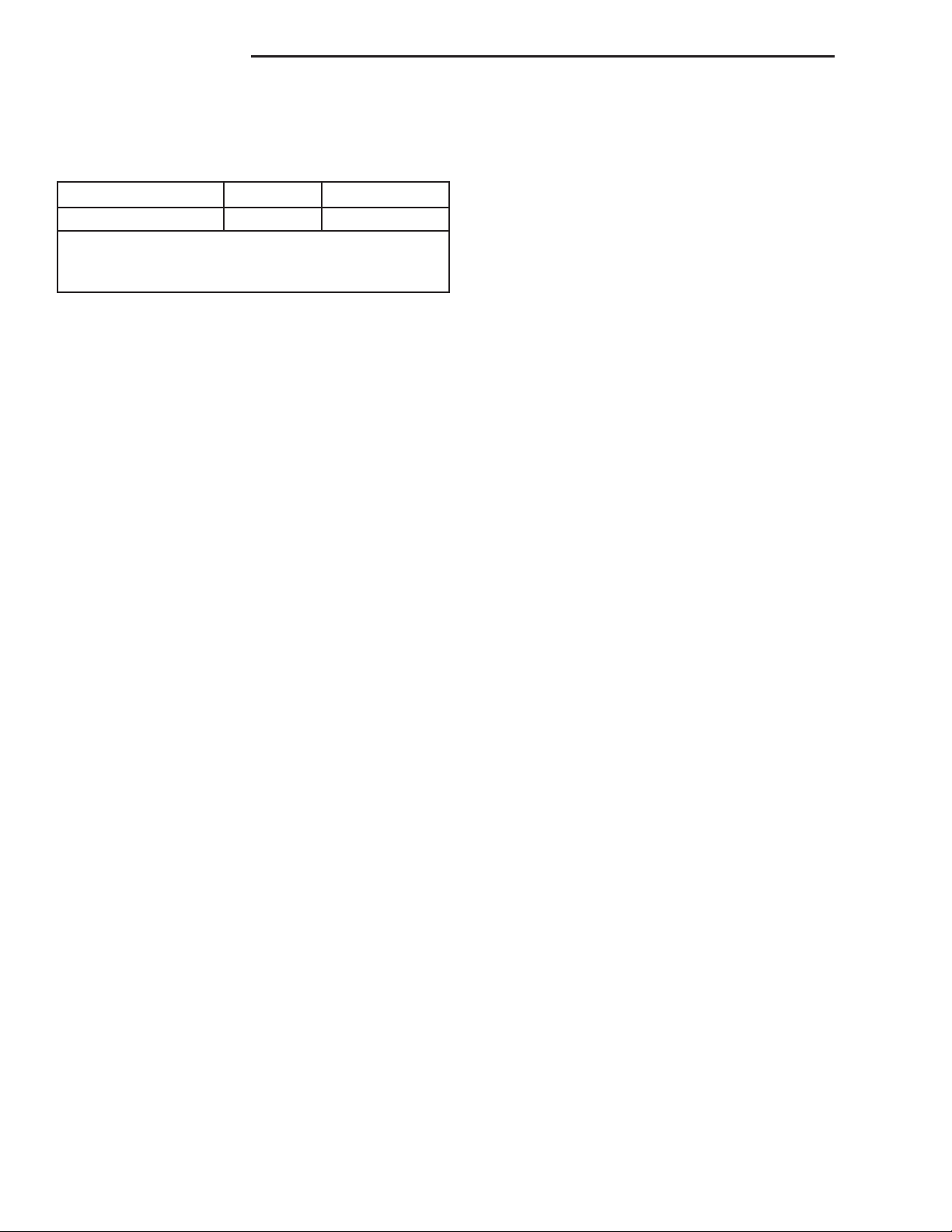
FUEL TANK CAPACITY
Models Liters U.S. Gallons
All 76 20
Nominal refill capacities are shown. A variation may
be observed from vehicle to vehicle due to
manufacturing tolerance and refill procedure.
FUEL SYSTEM PRESSURE
339 kPa 6 34 kPa (49.2 psi 6 5 psi).
TORQUE CHART
DESCRIPTION TORQUE
Accelerator Pedal Bracket Mounting Nuts . . . 5 N·m
(36 in. lbs.)
Fuel Hose Clamps ............3N·m(25in.lbs.)
Fuel Rail Mounting Bolts .....11N·m(100 in. lbs.)
Fuel Tank Mounting Strap Nuts .........10N·m
(90 in. lbs.)
Fuel Pump Module Locknut ....74N·m(55ft.lbs.)
Page 23

XJ FUEL SYSTEM 14 - 23
FUEL INJECTION SYSTEM
INDEX
page page
DESCRIPTION AND OPERATION
AIR CONDITIONING (A/C) CLUTCH RELAY—
PCM OUTPUT ......................... 33
AIR CONDITIONING (A/C) CONTROLS—PCM
INPUT ............................... 27
AUTO SHUTDOWN (ASD) RELAY—PCM
OUTPUT ............................. 33
AUTOMATIC SHUTDOWN (ASD) RELAY
SENSE—PCM INPUT ................... 28
BATTERY TEMPERATURE SENSOR—PCM
INPUT ............................... 28
BATTERY VOLTAGE—PCM INPUT ........... 28
BRAKE SWITCH—PCM INPUT .............. 28
CAMSHAFT POSITION SENSOR—PCM
INPUT ............................... 29
CCD BUS (+/-) CIRCUITS-PCM OUTPUTS ..... 34
CRANKSHAFT POSITION SENSOR—PCM
INPUT ............................... 29
DATA LINK CONNECTOR—PCM INPUT AND
OUTPUT ............................. 34
DUTY CYCLE EVAP PURGE SOLENOID
VALVE-PCM OUTPUT ................... 34
ENGINE COOLANT TEMPERATURE SENSOR—
PCM INPUT ........................... 29
EXTENDED IDLE SWITCH—PCM INPUT ...... 30
FIVE VOLT SENSOR SUPPLY—PRIMARY ..... 28
FIVE VOLT SENSOR SUPPLY—SECONDARY . . 28
FUEL INJECTORS—PCM OUTPUT .......... 34
FUEL LEVEL SENSOR—PCM INPUT ......... 28
FUEL PUMP RELAY-PCM OUTPUT .......... 35
GENERATOR FIELD DRIVER (-)—PCM
OUTPUT ............................. 35
GENERATOR FIELD SOURCE (+)—PCM
OUTPUT ............................. 35
GENERATOR LAMP—PCM OUTPUT ......... 35
GENERATOR OUTPUT—PCM INPUT ......... 30
IDLE AIR CONTROL (IAC) MOTOR—PCM
OUTPUT ............................. 35
IGNITION CIRCUIT SENSE—PCM INPUT ..... 30
IGNITION COIL—PCM OUTPUT ............. 35
INTAKE MANIFOLD AIR TEMPERATURE
SENSOR—PCM INPUT .................. 30
LEAK DETECTION PUMP (SWITCH) SENSE—
PCM INPUT ........................... 31
LEAK DETECTION PUMP—PCM OUTPUT ..... 35
MALFUNCTION INDICATOR LAMP—ECM/PCM
OUTPUT ............................. 35
MANIFOLD ABSOLUTE PRESSURE (MAP)
SENSOR—PCM INPUT .................. 31
MODES OF OPERATION .................. 25
OIL PRESSURE SENSOR—PCM INPUT ...... 31
OXYGEN SENSOR (HO2S)—PCM INPUT ..... 30
POWER GROUND .......................31
POWER STEERING PRESSURE SWITCH—
PCM INPUT ........................... 31
POWERTRAIN CONTROL MODULE (PCM) .... 24
RADIATOR FAN RELAY—PCM OUTPUT ...... 35
SENSOR RETURN—PCM INPUT ............ 32
SPEED CONTROL SOLENOIDS—PCM
OUTPUT ............................. 35
SPEED CONTROL SWITCHES—PCM INPUT . . . 32
TACHOMETER—PCM OUTPUT ............. 35
THROTTLE BODY ....................... 35
THROTTLE POSITION SENSOR (TPS)—PCM
INPUT ............................... 32
TRANSMISSION PARK/NEUTRAL SWITCH—
PCM INPUT ........................... 32
VEHICLE SPEED AND DISTANCE SENSOR—
PCM INPUT ........................... 32
DIAGNOSIS AND TESTING
ASD AND FUEL PUMP RELAYS ............. 39
ENGINE COOLANT TEMPERATURE
SENSOR ............................ 41
EXTENDED IDLE SWITCH TEST ............ 43
IDLE AIR CONTROL (IAC) MOTOR ........... 42
INTAKE MANIFOLD AIR TEMPERATURE
SENSOR ............................. 42
MANIFOLD ABSOLUTE PRESSURE (MAP)
SENSOR TEST ........................ 40
OXYGEN (O2S) SENSORS ................ 41
POWER STEERING PRESSURE SWITCH ..... 42
THROTTLE BODY MINIMUM AIR FLOW
CHECK PROCEDURE ................... 44
THROTTLE POSITION SENSOR (TPS) ....... 44
VEHICLE SPEED SENSOR ................ 43
VISUAL INSPECTION ..................... 36
REMOVAL AND INSTALLATION
AIR CLEANER ELEMENT (FILTER) .......... 49
AUTOMATIC SHUTDOWN (ASD) RELAY ...... 45
DUTY CYCLE EVAP CANISTER PURGE
SOLENOID ........................... 47
ENGINE COOLANT TEMPERATURE SENSOR . . 50
FUEL PUMP RELAY ...................... 45
IDLE AIR CONTROL (IAC) MOTOR ........... 47
INTAKE MANIFOLD AIR TEMPERATURE
SENSOR ............................. 50
MANIFOLD ABSOLUTE PRESSURE (MAP)
SENSOR ............................. 47
Page 24
14 - 24 FUEL SYSTEM XJ
OXYGEN SENSOR ....................... 48
POWER STEERING PRESSURE SWITCH—2.5L
ENGINE ............................. 48
POWERTRAIN CONTROL MODULE (PCM) .... 47
THROTTLE BODY ....................... 45
THROTTLE POSITION SENSOR (TPS) ....... 46
DESCRIPTION AND OPERATION
POWERTRAIN CONTROL MODULE (PCM)
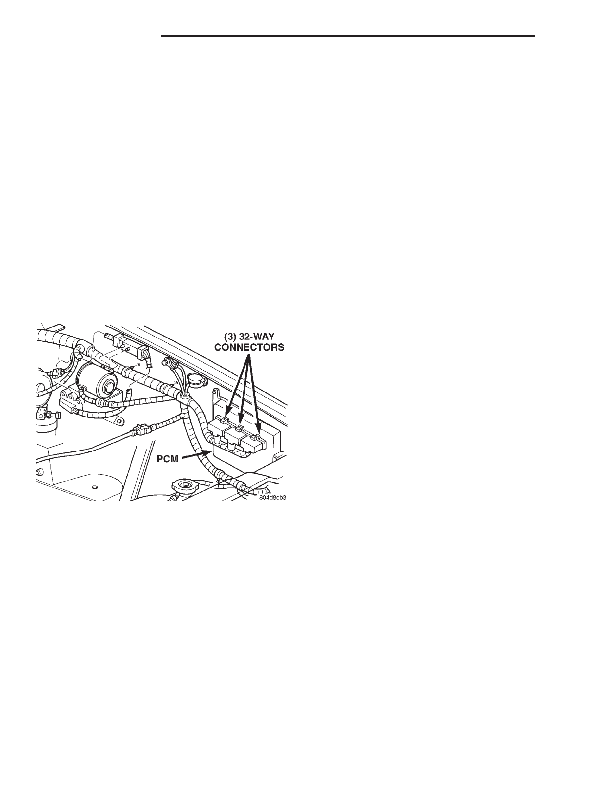
The Powertrain Control Module (PCM) (Fig. 1)
operates the fuel system. The PCM was formerly
referred to as the SBEC or engine controller. The
PCM is a pre-programmed, triple microprocessor digital computer. It regulates ignition timing, air-fuel
ratio, emission control devices, charging system, certain transmission features, speed control, air conditioning compressor clutch engagement and idle
speed. The PCM can adapt its programming to meet
changing operating conditions.
Fig. 1 PCM Location
The PCM receives input signals from various
switches and sensors. Based on these inputs, the
PCM regulates various engine and vehicle operations
through different system components. These components are referred to as Powertrain Control Module
(PCM) Outputs. The sensors and switches that provide inputs to the PCM are considered Powertrain
Control Module (PCM) Inputs.
The PCM adjusts ignition timing based upon
inputs it receives from sensors that react to: engine
rpm, manifold absolute pressure, engine coolant temperature, throttle position, transmission gear selection (automatic transmission), vehicle speed, power
steering pump pressure (2.5L engine only), and the
brake switch.
The PCM adjusts idle speed based on inputs it
receives from sensors that react to: throttle position,
vehicle speed, transmission gear selection, engine
VEHICLE SPEED SENSOR ................ 50
SPECIFICATIONS
TORQUE CHART ........................ 51
SPECIAL TOOLS
FUEL SYSTEM .......................... 52
coolant temperature and from inputs it receives from
the air conditioning clutch switch and brake switch.
Based on inputs that it receives, the PCM adjusts
ignition coil dwell. The PCM also adjusts the generator charge rate through control of the generator
field and provides speed control operation.
NOTE: PCM Inputs:
• A/C request (if equipped with factory A/C)
• A/C select (if equipped with factory A/C)
• Auto shutdown (ASD) sense
• Battery temperature
• Battery voltage
• Brake switch
• CCD bus (+) circuits
• CCD bus (-) circuits
• Camshaft position sensor signal
• Crankshaft position sensor
• Data link connection for DRB scan tool
• Engine coolant temperature sensor
• Extended idle switch (4.0L engine with police
package)
• Fuel level
• Generator (battery voltage) output
• Ignition circuit sense (ignition switch in on/off/
crank/run position)
• Intake manifold air temperature sensor
• Leak detection pump (switch) sense (if equipped)
• Manifold absolute pressure (MAP) sensor
• Oil pressure
• Oxygen sensors
• Park/neutral switch (auto. trans. only)
• Power ground
• Power steering pressure switch (2.5L engine
only)
• Sensor return
• Signal ground
• Speed control multiplexed single wire input
• Throttle position sensor
• Vehicle speed sensor
NOTE: PCM Outputs:
• A/C clutch relay
• Auto shutdown (ASD) relay
• CCD bus (+/-) circuits for: speedometer, voltme-
ter, fuel gauge, oil pressure gauge/lamp, engine temp.
gauge and speed control warn. lamp
• Data link connection for DRB scan tool
Page 25

XJ FUEL SYSTEM 14 - 25
DESCRIPTION AND OPERATION (Continued)
• EGR valve control solenoid (if equipped)
• EVAP canister purge solenoid
• Five volt sensor supply (primary)
• Five volt sensor supply (secondary)
• Fuel injectors
• Fuel pump relay
• Generator field driver (-)
• Generator field driver (+)
• Idle air control (IAC) motor
• Ignition coil
• Leak detection pump (if equipped)
• Malfunction indicator lamp (Check engine lamp).
Driven through CCD circuits.
• Radiator cooling fan relay
• Speed control vacuum solenoid
• Speed control vent solenoid
• Tachometer (if equipped). Driven through CCD
circuits.
• Transmission convertor clutch circuit
MODES OF OPERATION
As input signals to the powertrain control module
(PCM) change, the PCM adjusts its response to the
output devices. For example, the PCM must calculate
different injector pulse width and ignition timing for
idle than it does for wide open throttle (WOT).
The PCM will operate in two different modes:
Open Loop and Closed Loop.
During Open Loop modes, the powertrain control
module (PCM) receives input signals and responds
only according to preset PCM programming. Input
from the oxygen (O2S) sensors is not monitored during Open Loop modes.
During Closed Loop modes, the PCM will monitor
the oxygen (O2S) sensors input. This input indicates
to the PCM whether or not the calculated injector
pulse width results in the ideal air-fuel ratio. This
ratio is 14.7 parts air-to-1 part fuel. By monitoring
the exhaust oxygen content through the O2S sensor,
the PCM can fine tune the injector pulse width. This
is done to achieve optimum fuel economy combined
with low emission engine performance.
The fuel injection system has the following modes
of operation:
• Ignition switch ON
• Engine start-up (crank)
• Engine warm-up
• Idle
• Cruise
• Acceleration
• Deceleration
• Wide open throttle (WOT)
• Ignition switch OFF
The ignition switch On, engine start-up (crank),
engine warm-up, acceleration, deceleration and wide
open throttle modes are Open Loop modes. The idle
and cruise modes, (with the engine at operating temperature) are Closed Loop modes.
IGNITION SWITCH (KEY-ON) MODE
This is an Open Loop mode. When the fuel system
is activated by the ignition switch, the following
actions occur:
• The powertrain control module (PCM) pre-posi-
tions the idle air control (IAC) motor.
• The PCM determines atmospheric air pressure
from the MAP sensor input to determine basic fuel
strategy.
• The PCM monitors the engine coolant temperature sensor input. The PCM modifies fuel strategy
based on this input.
• Intake manifold air temperature sensor input is
monitored.
• Throttle position sensor (TPS) is monitored.
• The auto shutdown (ASD) relay is energized by
the PCM for approximately three seconds.
• The fuel pump is energized through the fuel
pump relay by the PCM. The fuel pump will operate
for approximately three seconds unless the engine is
operating or the starter motor is engaged.
• The O2S sensor heater element is energized via
the ASD relay. The O2S sensor input is not used by
the PCM to calibrate air-fuel ratio during this mode
of operation.
ENGINE START-UP MODE
This is an Open Loop mode. The following actions
occur when the starter motor is engaged.
The powertrain control module (PCM) receives
inputs from:
• Battery voltage
• Engine coolant temperature sensor
• Crankshaft position sensor
• Intake manifold air temperature sensor
• Manifold absolute pressure (MAP) sensor
• Throttle position sensor (TPS)
• Camshaft position sensor signal
The PCM monitors the crankshaft position sensor.
If the PCM does not receive a crankshaft position
sensor signal within 3 seconds of cranking the
engine, it will shut down the fuel injection system.
The fuel pump is activated by the PCM through
the fuel pump relay.
Voltage is applied to the fuel injectors with the
ASD relay via the PCM. The PCM will then control
the injection sequence and injector pulse width by
turning the ground circuit to each individual injector
on and off.
The PCM determines the proper ignition timing
according to input received from the crankshaft position sensor.
Page 26

14 - 26 FUEL SYSTEM XJ
DESCRIPTION AND OPERATION (Continued)
ENGINE WARM-UP MODE
This is an Open Loop mode. During engine warmup, the powertrain control module (PCM) receives
inputs from:
• Battery voltage
• Crankshaft position sensor
• Engine coolant temperature sensor
• Intake manifold air temperature sensor
• Manifold absolute pressure (MAP) sensor
• Throttle position sensor (TPS)
Camshaft position sensor signal (in the distributor)
•
• Park/neutral switch (gear indicator signal—auto.
trans. only)
• Air conditioning select signal (if equipped)
• Air conditioning request signal (if equipped)
Based on these inputs the following occurs:
• Voltage is applied to the fuel injectors with the
ASD relay via the PCM. The PCM will then control
the injection sequence and injector pulse width by
turning the ground circuit to each individual injector
on and off.
• The PCM adjusts engine idle speed through the
idle air control (IAC) motor and adjusts ignition timing.
• The PCM operates the A/C compressor clutch
through the A/C compressor clutch relay. This is done
if A/C has been selected by the vehicle operator and
specified pressures are met at the high and low–pressure A/C switches. Refer to Group 24, Heating and
Air Conditioning for additional information.
• When engine has reached operating temperature, the PCM will begin monitoring O2S sensor
input. The system will then leave the warm-up mode
and go into closed loop operation.
IDLE MODE
When the engine is at operating temperature, this
is a Closed Loop mode. At idle speed, the powertrain
control module (PCM) receives inputs from:
• Air conditioning select signal (if equipped)
• Air conditioning request signal (if equipped)
• Battery voltage
• Crankshaft position sensor
• Engine coolant temperature sensor
• Extended idle switch (4.0L engine with police
package only)
• Intake manifold air temperature sensor
• Manifold absolute pressure (MAP) sensor
• Throttle position sensor (TPS)
• Camshaft position sensor signal (in the distribu-
tor)
• Battery voltage
• Park/neutral switch (gear indicator signal—auto.
trans. only)
• Oxygen sensors
• Power steering pressure switch (2.5L engine
only)
Based on these inputs, the following occurs:
• Voltage is applied to the fuel injectors with the
ASD relay via the PCM. The PCM will then control
injection sequence and injector pulse width by turning the ground circuit to each individual injector on
and off.
• The PCM monitors the O2S sensor input and
adjusts air-fuel ratio by varying injector pulse width.
It also adjusts engine idle speed through the idle air
control (IAC) motor.
• The PCM adjusts ignition timing by increasing
and decreasing spark advance.
• The PCM operates the A/C compressor clutch
through the A/C compressor clutch relay. This is done
if A/C has been selected by the vehicle operator and
specified pressures are met at the high and low–pressure A/C switches. Refer to Group 24, Heating and
Air Conditioning for additional information.
The optional Extended Idle Switch is used to raise
and hold the engine idle speed to approximately 1000
rpm. This is when the shifter is in either the Park or
Neutral position and throttle pedal is not used. A
rocker-type switch (extended idle switch) is mounted
to the instrument panel. This switch will supply a
ground circuit (input) to the powertrain control module (PCM). The switch is available only with 4.0L
engine when supplied with optional police
package.
On 2.5L 4–cylinder engines, a power steering pressure switch is used to supply an input to the PCM
when steering pump pressure is high. This will raise
engine speed. Refer to Power Steering Pressure
Switch in this group for additional information. The
4.0L 6–cylinder engine does not use this switch.
CRUISE MODE
When the engine is at operating temperature, this
is a Closed Loop mode. At cruising speed, the powertrain control module (PCM) receives inputs from:
• Air conditioning select signal (if equipped)
• Air conditioning request signal (if equipped)
• Battery voltage
• Engine coolant temperature sensor
• Crankshaft position sensor
• Intake manifold air temperature sensor
• Manifold absolute pressure (MAP) sensor
• Throttle position sensor (TPS)
• Camshaft position sensor signal (in the distribu-
tor)
• Park/neutral switch (gear indicator signal—auto.
trans. only)
• Oxygen (O2S) sensors
Based on these inputs, the following occurs:
Page 27

XJ FUEL SYSTEM 14 - 27
DESCRIPTION AND OPERATION (Continued)
• Voltage is applied to the fuel injectors with the
ASD relay via the PCM. The PCM will then adjust
the injector pulse width by turning the ground circuit
to each individual injector on and off.
• The PCM monitors the O2S sensor input and
adjusts air-fuel ratio. It also adjusts engine idle
speed through the idle air control (IAC) motor.
• The PCM adjusts ignition timing by turning the
ground path to the coil on and off.
• The PCM operates the A/C compressor clutch
through the clutch relay. This happens if A/C has
been selected by the vehicle operator and requested
by the A/C thermostat.
ACCELERATION MODE
This is an Open Loop mode. The powertrain control
module (PCM) recognizes an abrupt increase in
throttle position or MAP pressure as a demand for
increased engine output and vehicle acceleration. The
PCM increases injector pulse width in response to
increased throttle opening.
DECELERATION MODE
When the engine is at operating temperature, this
is an Open Loop mode. During hard deceleration, the
powertrain control module (PCM) receives the following inputs.
• Air conditioning select signal (if equipped)
• Air conditioning request signal (if equipped)
• Battery voltage
• Engine coolant temperature sensor
• Crankshaft position sensor
• Intake manifold air temperature sensor
• Manifold absolute pressure (MAP) sensor
• Throttle position sensor (TPS)
• Camshaft position sensor signal (in the distribu-
tor)
• Park/neutral switch (gear indicator signal—auto.
trans. only)
• Vehicle speed sensor
If the vehicle is under hard deceleration with the
proper rpm and closed throttle conditions, the PCM
will ignore the oxygen sensor input signal. The PCM
will enter a fuel cut-off strategy in which it will not
supply a ground to the injectors. If a hard deceleration does not exist, the PCM will determine the
proper injector pulse width and continue injection.
Based on the above inputs, the PCM will adjust
engine idle speed through the idle air control (IAC)
motor.
The PCM adjusts ignition timing by turning the
ground path to the coil on and off.
WIDE OPEN THROTTLE MODE
This is an Open Loop mode. During wide open
throttle operation, the powertrain control module
(PCM) receives the following inputs.
• Battery voltage
• Crankshaft position sensor
• Engine coolant temperature sensor
• Intake manifold air temperature sensor
• Manifold absolute pressure (MAP) sensor
• Throttle position sensor (TPS)
• Camshaft position sensor signal (in the distribu-
tor)
During wide open throttle conditions, the following
occurs:
• Voltage is applied to the fuel injectors with the
ASD relay via the PCM. The PCM will then control
the injection sequence and injector pulse width by
turning the ground circuit to each individual injector
on and off. The PCM ignores the oxygen sensor input
signal and provides a predetermined amount of additional fuel. This is done by adjusting injector pulse
width.
• The PCM adjusts ignition timing by turning the
ground path to the coil on and off.
IGNITION SWITCH OFF MODE
When ignition switch is turned to OFF position,
the PCM stops operating the injectors, ignition coil,
ASD relay and fuel pump relay.
AIR CONDITIONING (A/C) CONTROLS—PCM
INPUT
OPERATION
The A/C control system information applies to factory installed air conditioning units.
A/C SELECT SIGNAL: When the A/C switch is in
the ON position, an input signal is sent to the Powertrain Control Module (PCM). The signal informs
the PCM that the A/C has been selected. The PCM
adjusts idle speed to a pre-programmed rpm through
the idle air control (IAC) motor to compensate for
increased engine load.
A/C REQUEST SIGNAL: Once A/C has been
selected, the PCM receives the A/C request signal
from the clutch cycling pressure switch. The input
indicates that the evaporator pressure is in the
proper range for A/C application. The PCM uses this
input to cycle the A/C compressor clutch (through the
A/C relay). It will also determine the correct engine
idle speed through the idle air control (IAC) motor
position.
If the A/C low-pressure switch or high-pressure
switch opens (indicating a low or high refrigerant
pressure), the PCM will not receive an A/C request
signal. The PCM will then remove the ground from
Page 28
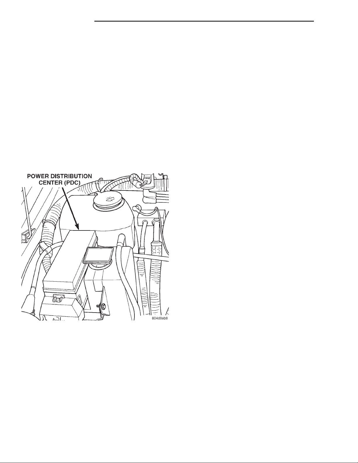
14 - 28 FUEL SYSTEM XJ
DESCRIPTION AND OPERATION (Continued)
the A/C relay. This will deactivate the A/C compressor clutch.
If the switch opens, (indicating that evaporator is
not in proper pressure range), the PCM will not
receive the A/C request signal. The PCM will then
remove the ground from the A/C relay, deactivating
the A/C compressor clutch.
AUTOMATIC SHUTDOWN (ASD) RELAY
SENSE—PCM INPUT
A 12 volt signal at this input indicates to the PCM
that the ASD has been activated. The ASD relay is
located in the Power Distribution Center (PDC). The
PDC is located in the engine compartment (Fig. 2).
Refer to label on PDC cover for relay location. The
relay is used to connect the oxygen sensor heater elements, ignition coil and fuel injectors to 12 volt +
power supply.
BATTERY VOLTAGE—PCM INPUT
OPERATION
The battery voltage input provides power to the
Powertrain Control Module (PCM). It also informs
the PCM what voltage level is supplied to the ignition coil and fuel injectors.
If battery voltage is low, the PCM will increase
injector pulse width (period of time that the injector
is energized). This is done to compensate for the
reduced flow through injector caused by the lowered
voltage.
BRAKE SWITCH—PCM INPUT
OPERATION
When the brake light switch is activated, the Powertrain Control Module (PCM) receives an input indicating that the brakes are being applied. After
receiving this input, the PCM maintains idle speed to
a scheduled rpm through control of the Idle Air Control (IAC) motor. The brake switch input is also used
to disable vent and vacuum solenoid output signals
to the speed control servo.
Fig. 2 Power Distribution Center (PDC)
This input is used only to sense that the ASD relay
is energized. If the powertrain control module (PCM)
does not see 12 volts at this input when the ASD
should be activated, it will set a diagnostic trouble
code (DTC).
BATTERY TEMPERATURE SENSOR—PCM
INPUT
OPERATION
Provides a signal to the PCM corresponding to the
battery temperature.
FIVE VOLT SENSOR SUPPLY—PRIMARY
OPERATION
Supplies the required 5 volt power source to the
crankshaft position sensor, camshaft position sensor,
MAP sensor and throttle position sensor.
FIVE VOLT SENSOR SUPPLY—SECONDARY
OPERATION
Supplies the required 5 volt source to certain sensors.
FUEL LEVEL SENSOR—PCM INPUT
OPERATION
The Powertrain Control Module (PCM) supplies
power to the fuel level sensor (fuel gauge sending
unit). The fuel level sensor will then return a signal
to the PCM to indicate fuel level. The purpose of this
feature is to prevent a false setting of misfire and
fuel system monitor trouble codes. This is if the fuel
level is less than approximately 15 percent, or, if
equipped with a Leak Detection Pump (LDP), more
than approximately 85 percent of its rated capacity.
This input is also used to send a signal to the PCM
for fuel gauge operation via the CCD or J1850 bus
circuits.
Page 29
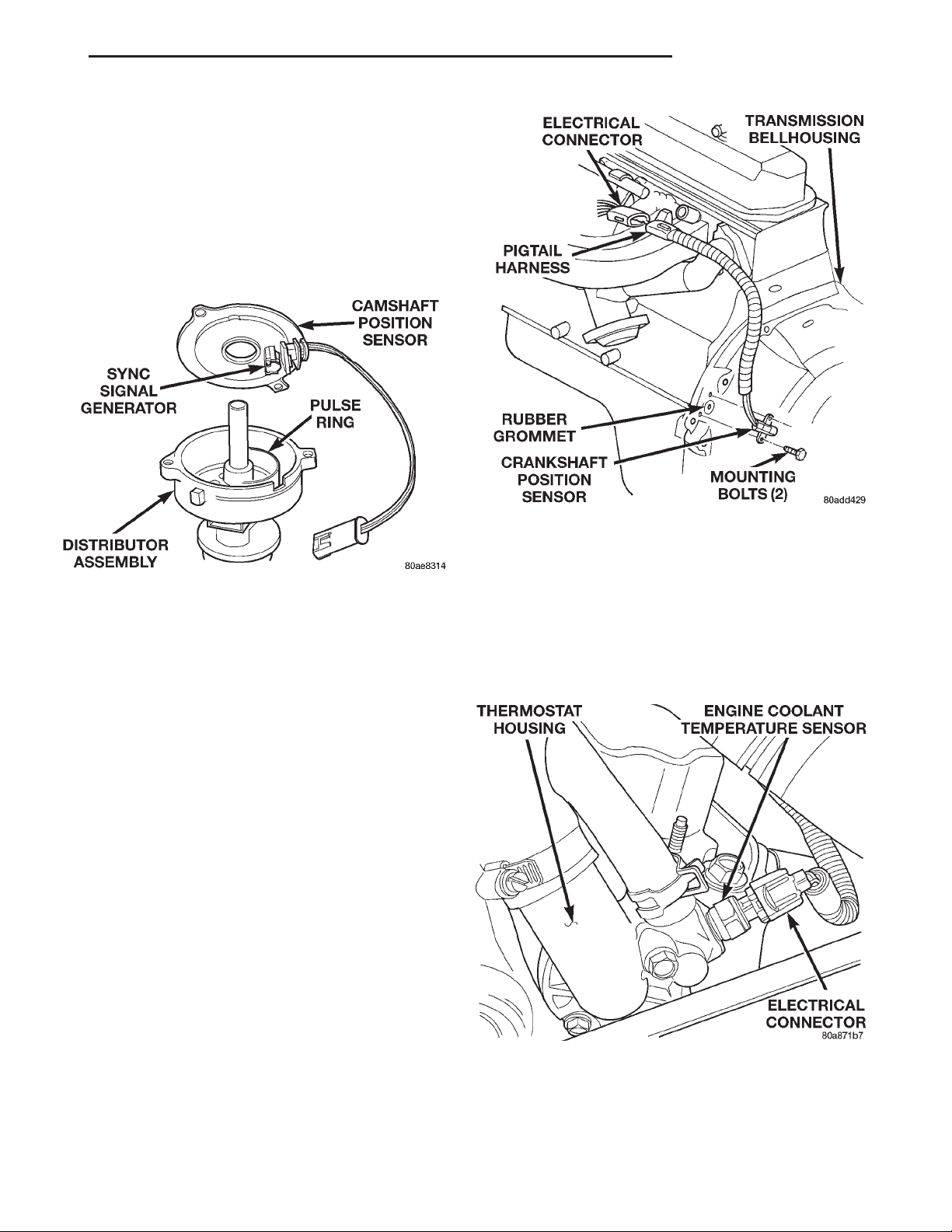
XJ FUEL SYSTEM 14 - 29
DESCRIPTION AND OPERATION (Continued)
CAMSHAFT POSITION SENSOR—PCM INPUT
A sync signal is provide by the camshaft position
sensor located in the distributor (Fig. 3). The sync
signal from this sensor works in conjunction with the
crankshaft position sensor to provide the Powertrain
Control Module (PCM) with inputs. This is done to
establish and maintain correct injector firing order.
Refer to Camshaft Position Sensor in Group 8D,
Ignition System for more information.
Fig. 3 Camshaft Position Sensor—Typical
CRANKSHAFT POSITION SENSOR—PCM
INPUT
This sensor is a hall effect device that detects
notches in the flywheel (manual transmission) or
flexplate (automatic transmission).
This sensor is used to indicate to the powertrain
control module (PCM) that a spark and or fuel injection event is to be required. The output from this
sensor, in conjunction with the camshaft position sensor signal, is used to differentiate between fuel injection and spark events.
The sensor is bolted to the transmission bellhousing (Fig. 4).
Refer to Group 8D, Ignition System for more
crankshaft position sensor information.
The engine will not operate if the PCM does not
receive a crankshaft position sensor input.
ENGINE COOLANT TEMPERATURE SENSOR—
PCM INPUT
The engine coolant temperature sensor is installed
in the thermostat housing (Fig. 5) and protrudes into
the water jacket. The sensor provides an input voltage to the Powertrain Control Module (PCM) relating
coolant temperature. The PCM uses this input along
with inputs from other sensors to determine injector
pulse width and ignition timing. As coolant temperature varies, the coolant temperature sensor’s resis-
Fig. 4 Crankshaft Position Sensor—Typical
tance changes. The change in resistance results in a
different input voltage to the PCM.
When the engine is cold, the PCM will operate in
Open Loop cycle. It will demand slightly richer airfuel mixtures and higher idle speeds. This is done
until normal operating temperatures are reached.
Refer to Open Loop/Closed Loop Modes of Operation in this section of the group for more information.
Fig. 5 Engine Coolant Temperature Sensor—Typical
Page 30
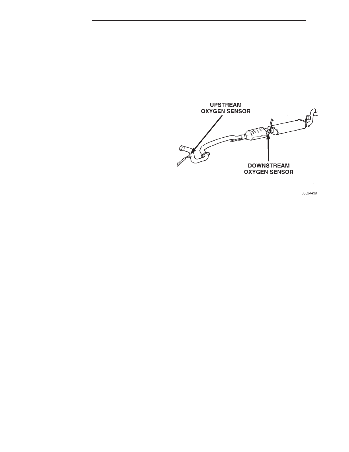
14 - 30 FUEL SYSTEM XJ
DESCRIPTION AND OPERATION (Continued)
EXTENDED IDLE SWITCH—PCM INPUT
OPTIONAL POLICE PACKAGE WITH 4.0L ENGINE ONLY
The extended idle switch is used to raise the
engine idle speed to approximately 1000 rpm. This is
when the shifter is in either the Park or Neutral
position. A rocker-type switch (extended idle switch)
is mounted to the instrument panel. This switch will
supply a ground circuit to the powertrain control
module (PCM). The switch is available only with
4.0L engine when supplied with the optional
police package.
For testing and diagnosis of this switch and its circuit, refer to the Diagnosis and Testing section of this
group.
GENERATOR OUTPUT—PCM INPUT
OPERATION
Provides a charging system voltage input to the
Powertrain Control Module (PCM). It is sensed at the
battery input to the PCM.
OXYGEN SENSOR (HO2S)—PCM INPUT
Two heated O2S sensors are used. The sensors produce voltages from 0 to 1 volt, depending upon the
oxygen content of the exhaust gas in the exhaust
manifold. When a large amount of oxygen is present
(caused by a lean air/fuel mixture), the sensors produces a low voltage. When there is a lesser amount
present (rich air/fuel mixture) it produces a higher
voltage. By monitoring the oxygen content and converting it to electrical voltage, the sensors act as a
rich-lean switch.
The oxygen sensors are equipped with a heating
element that keeps the sensors at proper operating
temperature during all operating modes. Maintaining
correct sensor temperature at all times allows the
system to enter into closed loop operation sooner.
Also, it allows the system to remain in closed loop
operation during periods of extended idle.
In Closed Loop operation, the PCM monitors the
O2S sensor input (along with other inputs) and
adjusts the injector pulse width accordingly. During
Open Loop operation, the PCM ignores the O2S sensor input. The PCM adjusts injector pulse width
based on preprogrammed (fixed) values and inputs
from other sensors.
The Automatic Shutdown (ASD) relay supplies battery voltage to both the upstream and downstream
heated oxygen sensors. The oxygen sensors are
equipped with a heating element. The heating elements reduce the time required for the sensors to
reach operating temperature.
UPSTREAM HEATED OXYGEN SENSOR
The upstream O2S sensor is located in the exhaust
downpipe (Fig. 6). It provides an input voltage to the
PCM. The input tells the PCM the oxygen content of
the exhaust gas. The PCM uses this information to
fine tune the air/fuel ratio by adjusting injector pulse
width.
Fig. 6 Heated Oxygen Sensors
DOWNSTREAM HEATED OXYGEN SENSOR
The downstream heated oxygen sensor is located
near the outlet end of the catalytic convertor (Fig. 6).
The downstream heated oxygen sensor input is used
to detect catalytic convertor deterioration. As the convertor deteriorates, the input from the downstream
sensor begins to match the upstream sensor input
except for a slight time delay. By comparing the
downstream heated oxygen sensor input to the input
from the upstream sensor, the PCM calculates catalytic convertor efficiency.
When the catalytic converter efficiency drops below
emission standards, the PCM stores a diagnostic
trouble code and illuminates the Malfunction Indicator Lamp (MIL). For more information, refer to
Group 25, Emission Control Systems.
IGNITION CIRCUIT SENSE—PCM INPUT
OPERATION
The ignition circuit sense input tells the Powertrain Control Module (PCM) the ignition switch has
energized the ignition circuit.
INTAKE MANIFOLD AIR TEMPERATURE
SENSOR—PCM INPUT
The intake manifold air temperature sensor is
installed in the intake manifold with the sensor element extending into the air stream (Fig. 7) or (Fig.
8). The sensor provides an input voltage to the Powertrain Control Module (PCM) indicating intake man-
Page 31
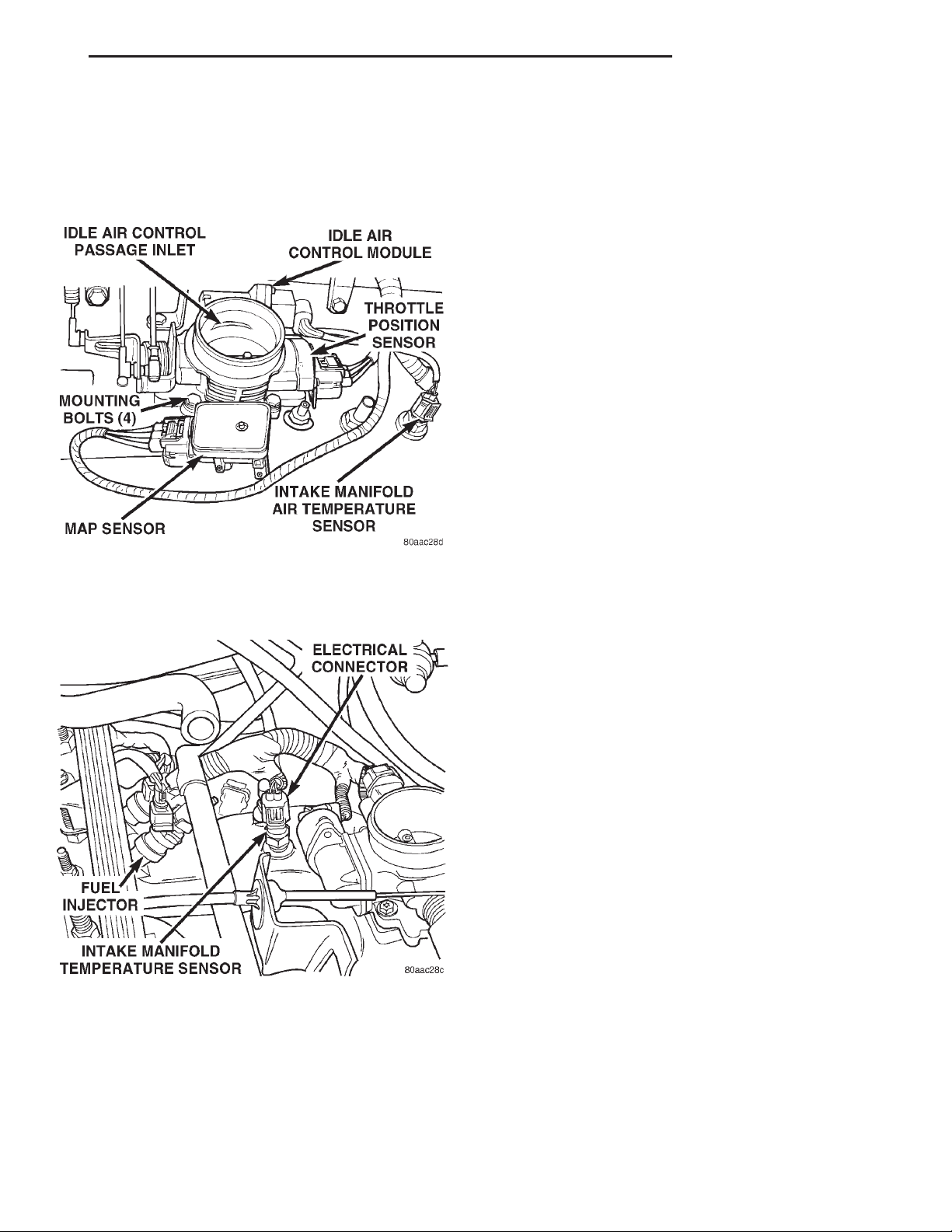
XJ FUEL SYSTEM 14 - 31
DESCRIPTION AND OPERATION (Continued)
ifold air temperature. The input is used along with
inputs from other sensors to determine injector pulse
width. As the temperature of the air-fuel stream in
the manifold varies, the sensor resistance changes.
This results in a different input voltage to the PCM.
MANIFOLD ABSOLUTE PRESSURE (MAP)
SENSOR—PCM INPUT
The MAP sensor reacts to absolute pressure in the
intake manifold. It provides an input voltage to the
Powertrain Control Module (PCM). As engine load
changes, manifold pressure varies. The change in
manifold pressure causes MAP sensor voltage to
change. The change in MAP sensor voltage results in
a different input voltage to the PCM. The input voltage level supplies the PCM with information about
ambient barometric pressure during engine load
while the engine is running. The PCM uses this
input along with inputs from other sensors to adjust
air-fuel mixture.
The MAP sensor is mounted on the side of the
engine throttle body (Fig. 7). The sensor is connected
to the throttle body with a rubber L-shaped fitting.
OIL PRESSURE SENSOR—PCM INPUT
DESCRIPTION
The engine oil pressure sensor (sending unit) is
located in an engine oil pressure gallery.
Fig. 7 Intake Man. Air Temp. Sensor Location—4.0L
Engine
LEAK DETECTION PUMP (SWITCH) SENSE—
Fig. 8 Intake Man. Air Temp. Sensor Location—2.5L
Engine
PCM INPUT
Provides an input to the PCM that the leak detection pump (LDP) has been activated. Refer to Group
25, Emission Control System for LDP information.
OPERATION
A signal is sent from the oil pressure sensor to the
Powertrain Control Module (PCM) relating to engine
oil pressure.
POWER GROUND
OPERATION
The power ground is used to control ground circuits for the following Powertrain Control Module
(PCM) loads:
• Generator field winding
• Fuel injectors
• Ignition coil(s)
• Certain relays/solenoids
POWER STEERING PRESSURE SWITCH—PCM
INPUT
A pressure sensing switch is included in the power
steering system (mounted on the high-pressure line).
This switch will be used only on vehicles equipped
with a 2.5L engine and power steering. The switch
(Fig. 9) provides an input to the Powertrain Control
Module (PCM). This input is provided during periods
of high pump load and low engine rpm; such as during parking maneuvers. The PCM will then increase
the idle speed through the Idle Air Control (IAC)
motor. This is done to prevent the engine from stalling under the increased load.
When steering pump pressure exceeds 3275 kPa 6
690 kPa (475 psi 6 100 psi), the normally closed
Page 32
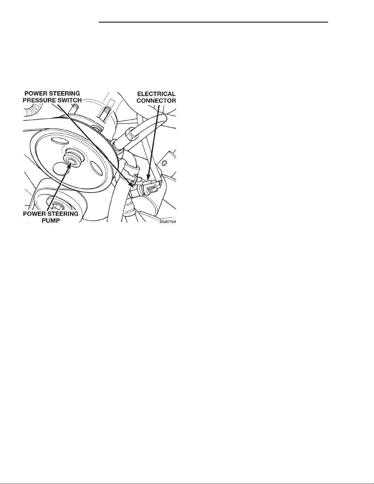
14 - 32 FUEL SYSTEM XJ
DESCRIPTION AND OPERATION (Continued)
switch will open and the PCM will increase the
engine idle speed. This will prevent the engine from
stalling.
When pump pressure drops to approximately 1379
kPa (200 psi), the switch circuit will re-close and
engine idle speed will return to its previous setting.
Fig. 9 Power Steering Pump Pressure Switch—2.5L
Engine
SENSOR RETURN—PCM INPUT
OPERATION
Sensor Return provides a low noise ground reference for all engine control system sensors.
SPEED CONTROL SWITCHES—PCM INPUT
Two separate speed control switch modules are
mounted on the steering wheel to the left and right
side of the driver’s airbag module. Within the two
switch modules, five momentary contact switches,
supporting seven different speed control functions
are used. The outputs from these switches are filtered into one input. The Powertrain Control Module
(PCM) determines which output has been applied
through resistive multiplexing. The input circuit
voltage is measured by the PCM to determine which
switch function has been selected.
A speed control indicator lamp, located on the
instrument panel cluster is energized by the PCM via
the CCD Bus. This occurs when speed control system
power has been turned ON, and the engine is running.
The two switch modules are labeled: ON/OFF, SET,
RESUME/ACCEL, CANCEL and COAST. Refer to
Group 8H, Speed Control System for more information.
TRANSMISSION PARK/NEUTRAL SWITCH—
PCM INPUT
The park/neutral switch is located on the transmission housing and provides an input to the Powertrain
Control Module (PCM). This will indicate that the
automatic transmission is in Park, Neutral or a drive
gear selection. This input is used to determine idle
speed (varying with gear selection), fuel injector
pulse width and ignition timing advance. Refer to
Group 21, Transmissions, for testing, replacement
and adjustment information. It is also used as a condition for speed control operation.
THROTTLE POSITION SENSOR (TPS)—PCM
INPUT
The TPS is mounted on the throttle body (Fig. 7).
The TPS is a variable resistor that provides the Powertrain Control Module (PCM) with an input signal
(voltage) that represents throttle blade position. The
sensor is connected to the throttle blade shaft. As the
position of the throttle blade changes, the resistance
of the TPS changes.
The PCM supplies approximately 5 volts to the
TPS. The TPS output voltage (input signal to the
PCM) represents the throttle blade position. The
PCM receives an input signal voltage from the TPS.
This will vary in an approximate range of from .26
volts at minimum throttle opening (idle), to 4.49 volts
at wide open throttle. Along with inputs from other
sensors, the PCM uses the TPS input to determine
current engine operating conditions. In response to
engine operating conditions, the PCM will adjust fuel
injector pulse width and ignition timing.
VEHICLE SPEED AND DISTANCE SENSOR—
PCM INPUT
The vehicle speed sensor is located on the speedometer pinion gear adapter (Fig. 10) or (Fig. 11). The
pinion gear adapter is located on the extension housing of the transmission (drivers side—2WD), or on
the transfer case (4WD). The sensor input is used by
the powertrain control module (PCM) to determine
vehicle speed and distance traveled.
The speed sensor generates 8 pulses per sensor
revolution. These signals, in conjunction with a
closed throttle signal from the throttle position sensor, indicate a closed throttle deceleration to the
PCM. When the vehicle is stopped at idle, a closed
throttle signal is received by the PCM (but a speed
sensor signal is not received).
Under deceleration conditions, the PCM adjusts
the idle air control (IAC) motor to maintain a desired
MAP value. Under idle conditions, the PCM adjusts
the IAC motor to maintain a desired engine speed.
Page 33
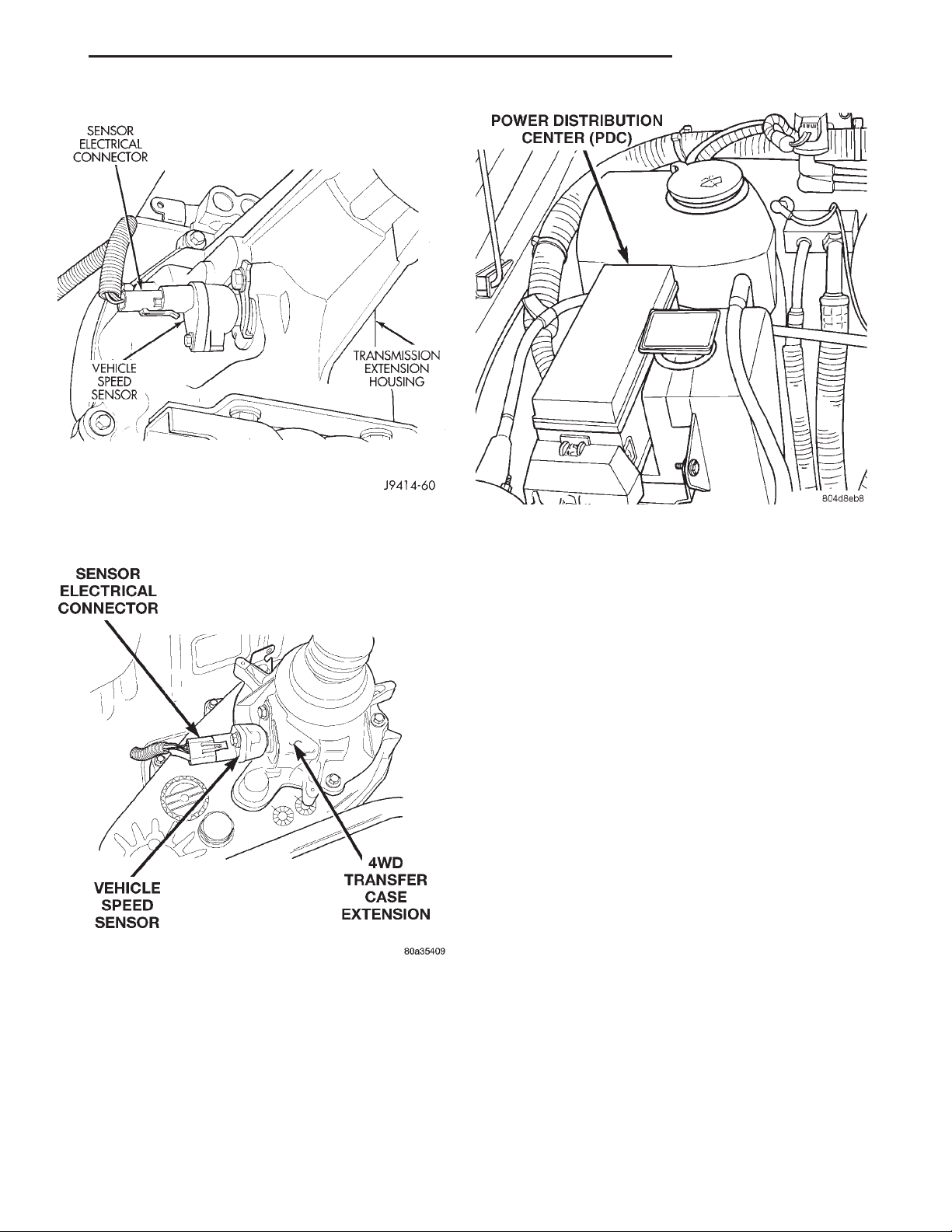
XJ FUEL SYSTEM 14 - 33
DESCRIPTION AND OPERATION (Continued)
Fig. 10 Vehicle Speed Sensor Location—2WD—
Typical
Fig. 11 Vehicle Speed Sensor Location—4WD—
Typical
AIR CONDITIONING (A/C) CLUTCH RELAY—
PCM OUTPUT
The A/C relay is located in the Power Distribution
Center (PDC). The PDC is located in the engine compartment (Fig. 12). Refer to label on PDC cover for
relay location.
Fig. 12 Power Distribution Center (PDC)
The powertrain control module (PCM) activates the
A/C compressor through the A/C clutch relay. The
PCM regulates A/C compressor operation by switching the ground circuit for the A/C clutch relay on and
off.
When the PCM receives a request for A/C from A/C
evaporator switch, it will adjust idle air control (IAC)
motor position. This is done to increase idle speed.
The PCM will then activate the A/C clutch through
the A/C clutch relay. The PCM adjusts idle air control
(IAC) stepper motor position to compensate for
increased engine load from the A/C compressor.
By switching the ground path for the relay on and
off, the PCM is able to cycle the A/C compressor
clutch. This is based on changes in engine operating
conditions. The PCM will also de-energize the relay if
coolant temperature exceeds 125°C (257°F).
AUTO SHUTDOWN (ASD) RELAY—PCM
OUTPUT
DESCRIPTION
The ASD relay is located in the Power Distribution
Center (PDC).
OPERATION
The ASD supplies battery voltage to the fuel injectors and ignition coil(s). With certain emissions packages it also supplys voltage to the oxygen sensor
heating elements. The ground circuit for the coil in
the ASD relay is controlled by the Powertrain Control Module (PCM). The PCM operates the relay by
switching the ground circuit on and off.
Page 34
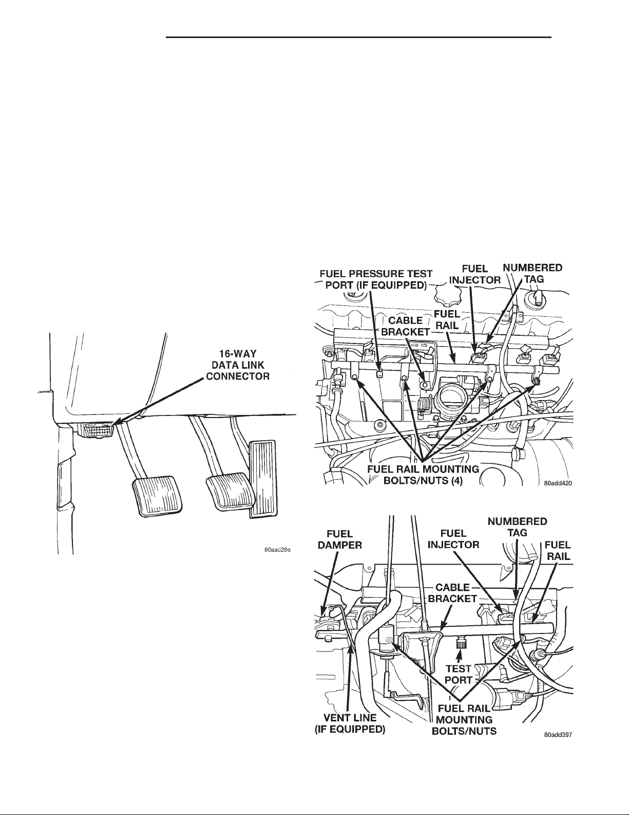
14 - 34 FUEL SYSTEM XJ
DESCRIPTION AND OPERATION (Continued)
CCD BUS (+/-) CIRCUITS-PCM OUTPUTS
The Powertrain Control Module (PCM) sends certain output signals through the CCD bus circuits.
These signals are used to control certain instrument
panel located items and to determine certain identification numbers.
Refer to Group 8E, Instrument Panel and Gauges
for additional information.
DATA LINK CONNECTOR—PCM INPUT AND
OUTPUT
The 16–way data link connector (diagnostic scan
tool connector) links the Diagnostic Readout Box
(DRB) scan tool or the Mopar Diagnostic System
(MDS) with the powertrain control module (PCM).
The data link connector is located under the instrument panel to the left of the steering column (Fig.
13). For operation of the DRB scan tool, refer to the
appropriate Powertrain Diagnostic Procedures service manual.
with an attached numerical tag (INJ 1, INJ 2 etc.).
This is used to identify each fuel injector.
The injectors are energized individually in a
sequential order by the powertrain control module
(PCM). The PCM will adjust injector pulse width by
switching the ground path to each individual injector
on and off. Injector pulse width is the period of time
that the injector is energized. The PCM will adjust
injector pulse width based on various inputs it
receives.
During start up, battery voltage is supplied to the
injectors through the ASD relay. When the engine is
operating, voltage is supplied by the charging system. The PCM determines injector pulse width based
on various inputs.
Fig. 13 Data Link Connector Location
DUTY CYCLE EVAP PURGE SOLENOID VALVE-PCM OUTPUT
Refer to Group 25, Emission Control System for
information.
FUEL INJECTORS—PCM OUTPUT
Six individual fuel injectors are used with the 4.0L
6-cylinder engine (Fig. 14). Four individual fuel injectors are used with the 2.5L 4-cylinder engine (Fig.
15). The fuel injectors are attached to the fuel rail.
The nozzle ends of the injectors are positioned into
openings in the intake manifold just above the intake
valve ports of the cylinder head. The engine wiring
harness connector for each fuel injector is equipped
Fig. 14 Fuel Rail and Injectors—4.0L 6–Cyl. Engine
Fig. 15 Fuel Rail and Injectors—2.5L 4–Cyl. Engine
Page 35

XJ FUEL SYSTEM 14 - 35
DESCRIPTION AND OPERATION (Continued)
FUEL PUMP RELAY-PCM OUTPUT
DESCRIPTION
The fuel pump relay is located in the Power Distribution Center (PDC).
OPERATION
The PCM energizes the electric fuel pump through
the fuel pump relay. Battery voltage is applied to the
fuel pump relay when the ignition key is ON. The
relay is energized when a ground signal is provided
by the PCM.
The fuel pump will operate for approximately three
seconds unless the engine is operating or the starter
motor is engaged.
GENERATOR FIELD SOURCE (+)—PCM
OUTPUT
OPERATION
This output from the Powertrain Control Module
(PCM) regulates charging system voltage to the generator field source (+) circuit. The voltage range is
12.9 to 15.0 volts. Models of previous years had used
the ASD relay (directly) to apply the 12 volt + power
supply to the generator field source (+) circuit.
GENERATOR FIELD DRIVER (-)—PCM OUTPUT
OPRATION
This output from the Powertrain Control Module
(PCM) regulates charging system ground control to
the generator field driver (-) circuit.
GENERATOR LAMP—PCM OUTPUT
If the powertrain control module (PCM) senses a
low charging condition in the charging system, it will
illuminate the generator lamp (if equipped) on the
instrument panel. For example, during low idle with
all accessories turned on, the lamp may momentarily
go on. Refer to Groups 8A and 8C for charging system information.
IDLE AIR CONTROL (IAC) MOTOR—PCM
OUTPUT
The IAC motor is mounted on the throttle body
(Fig. 7) and is controlled by the Powertrain Control
Module (PCM).
The throttle body has an air control passage that
provides air for the engine at idle (the throttle plate
is closed). The IAC motor pintle protrudes into the
air control passage and regulates air flow through it.
Based on various sensor inputs, the PCM adjusts
engine idle speed by moving the IAC motor pintle in
and out of the air control passage. The IAC motor is
positioned when the ignition key is turned to the On
position.
A (factory adjusted) set screw is used to mechanically limit the position of the throttle body throttle
plate. Never attempt to adjust the engine idle
speed using this screw. All idle speed functions are
controlled by the PCM.
IGNITION COIL—PCM OUTPUT
System voltage from the Automatic Shutdown
(ASD) relay is supplied to the ignition coil positive
terminal. The Powertrain Control Module (PCM)
operates the ignition coil. Ignition timing is not
adjustable. The PCM adjusts ignition timing to
meet changing engine operating conditions.
Refer to Group 8D, Ignition System for additional
information.
LEAK DETECTION PUMP—PCM OUTPUT
Certain engines with certain emissions packages
are equipped with a leak detection pump (LDP). The
LDP is activated through this PCM output. Refer to
Group 25, Emission Control System for additional
information.
RADIATOR FAN RELAY—PCM OUTPUT
An electric radiator cooling fan is used with certain
models/engines. It is controlled by the powertrain
control module (PCM) through the radiator fan relay.
The relay is energized when coolant temperature is
above 103°C (217°F). It will then de-energize when
coolant temperature drops to 98°C (208°F). Refer to
Group 7, Cooling Systems for more information.
The relay is located in the power distribution center (PDC) (Fig. 12).
MALFUNCTION INDICATOR LAMP—ECM/PCM
OUTPUT
Refer to Group 25, Emission Control System for
information.
SPEED CONTROL SOLENOIDS—PCM OUTPUT
Speed control operation is regulated by the powertrain control module (PCM). The PCM controls the
vacuum to the throttle actuator through the speed
control vacuum and vent solenoids. Refer to Group
8H for Speed Control Information.
TACHOMETER—PCM OUTPUT
The powertrain control module (PCM) supplies
engine rpm values to the instrument cluster tachometer. Refer to Group 8E for tachometer information.
THROTTLE BODY
Filtered air from the air cleaner enters the intake
manifold through the throttle body (Fig. 16). Fuel
Page 36
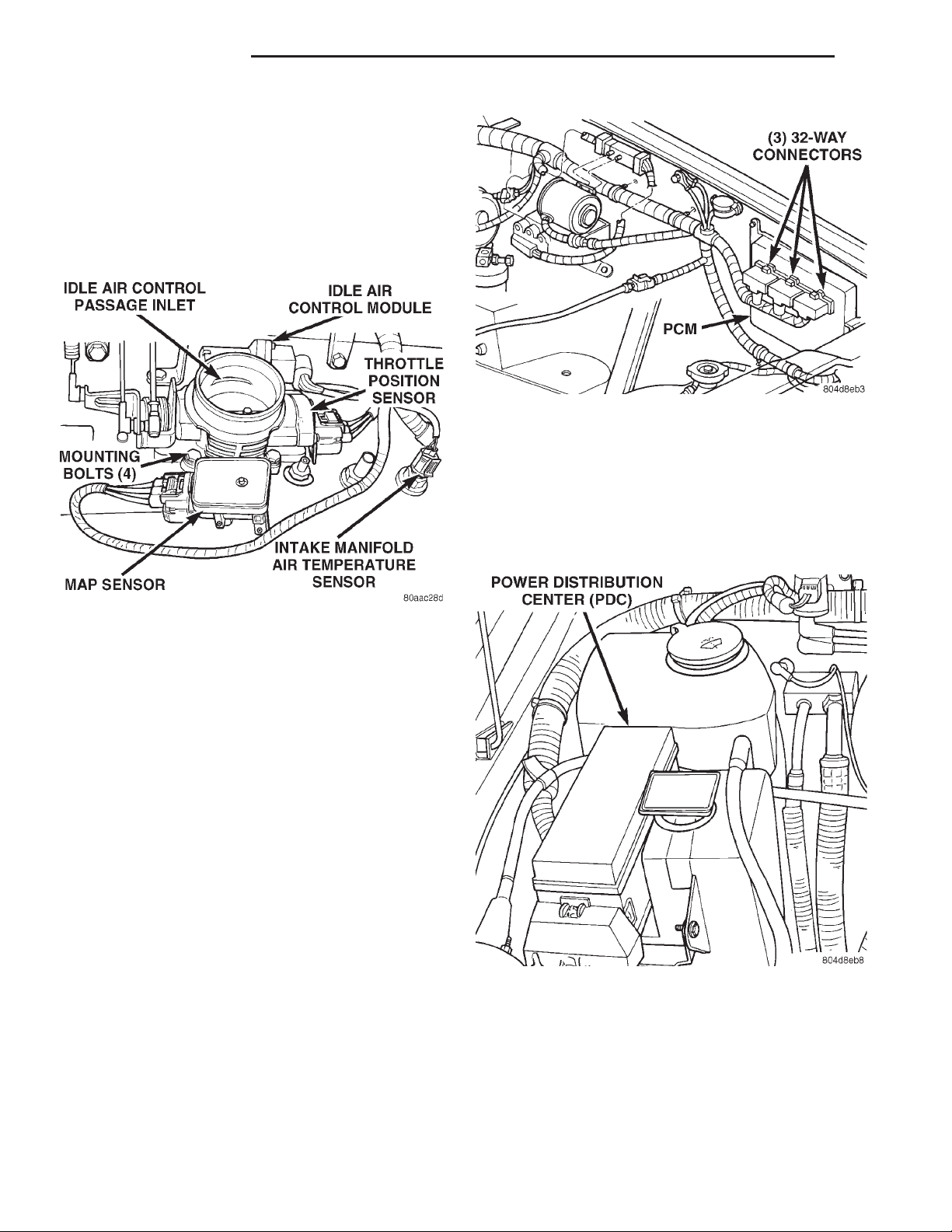
14 - 36 FUEL SYSTEM XJ
DESCRIPTION AND OPERATION (Continued)
does not enter the intake manifold through the throttle body. Fuel is sprayed into the manifold by the fuel
injectors. The throttle body is mounted on the intake
manifold. It contains an air control passage (Fig. 16)
controlled by an Idle Air Control (IAC) motor. The air
control passage is used to supply air for idle conditions. A throttle valve (plate) is used to supply air for
above idle conditions.
Fig. 17 Powertrain Control Module (PCM)
(3) Inspect fuel pump relay and air conditioning
compressor clutch relay (if equipped). Inspect ASD
relay connections. Inspect starter motor relay connections. Inspect relays for signs of physical damage and
corrosion. The relays are located in Power Distribution Center (PDC) (Fig. 18). Refer to label on PDC
cover for relay location.
Fig. 16 Throttle Body (4.0L Engine Shown)
The Throttle Position Sensor (TPS), IAC motor and
Manifold Absolute Pressure sensor (MAP) are
attached to the throttle body. The accelerator pedal
cable, speed control cable (when equipped) and automatic transmission control cable (when equipped) are
connected to the throttle arm.
A (factory adjusted) set screw is used to mechanically limit the position of the throttle body throttle
plate. Never attempt to adjust the engine idle
speed using this screw. All idle speed functions are
controlled by the PCM.
DIAGNOSIS AND TESTING
VISUAL INSPECTION
A visual inspection for loose, disconnected or incorrectly routed wires and hoses should be made. This
should be done before attempting to diagnose or service the fuel injection system. A visual check will
help spot these faults and save unnecessary test and
diagnostic time. A thorough visual inspection will
include the following checks:
(1) Verify the three 32–way electrical connectors
are fully inserted into the connector of the powertrain control module (PCM) (Fig. 17).
(2) Inspect battery cable connections. Be sure they
are clean and tight.
Fig. 18 Power Distribution Center (PDC)
(4) Inspect ignition coil connections. Verify coil secondary cable is firmly connected to coil (Fig. 19) or
(Fig. 20).
(5) Verify distributor cap is correctly attached to
distributor. Be sure spark plug cables are firmly connected to distributor cap and spark plugs are in their
correct firing order. Be sure coil cable is firmly connected to distributor cap and coil. Be sure camshaft
Page 37
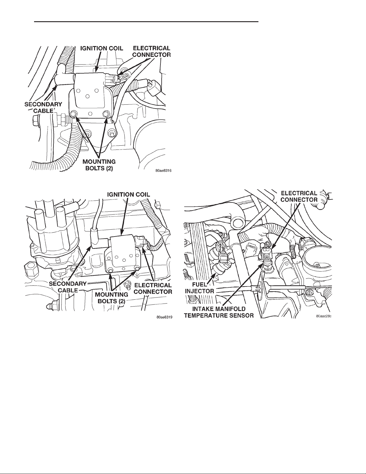
XJ FUEL SYSTEM 14 - 37
DIAGNOSIS AND TESTING (Continued)
(9) Inspect fuel tube quick-connect fitting-to-fuel
rail connections.
(10) Verify hose connections to all ports of vacuum
fittings on intake manifold are tight and not leaking.
(11) Inspect accelerator cable, transmission throttle cable (if equipped) and cruise control cable connections (if equipped). Check their connections to
throttle arm of throttle body for any binding or
restrictions.
(12) If equipped with vacuum brake booster, verify
vacuum booster hose is firmly connected to fitting on
intake manifold. Also check connection to brake vacuum booster.
(13) Inspect air cleaner inlet and air cleaner element for dirt or restrictions.
(14) Inspect radiator grille area, radiator fins and
air conditioning condenser for restrictions.
(15) Verify intake manifold air temperature sensor
wire connector is firmly connected to harness connec-
Fig. 19 Ignition Coil—2.5L Engine
tor (Fig. 21) or (Fig. 22).
Fig. 20 Ignition Coil—4.0L Engine
position sensor wire connector (at distributor) is
firmly connected to harness connector. Inspect spark
plug condition. Connect vehicle to an oscilloscope and
inspect spark events for fouled or damaged spark
plugs or cables. Refer to Group 8D, Ignition System
for additional information.
(6) Verify generator output wire, generator connector and ground wire are firmly connected to generator.
(7) Inspect system body grounds for loose or dirty
connections. Refer to Group 8, Wiring for ground
locations.
(8) Verify crankcase ventilation (CCV) operation.
Refer to Group 25, Emission Control System for additional information.
Fig. 21 Intake Manifold Air Temp. Sensor Location—
2.5L Engine
(16) Verify MAP sensor electrical connector is
firmly connected to MAP sensor (Fig. 22). Also verify
rubber L-shaped fitting from MAP sensor to throttle
body is firmly connected (Fig. 23).
(17) Verify fuel injector wire harness connectors
are firmly connected to injectors in correct order.
Each harness connector is numerically tagged with
injector number (INJ 1, INJ 2 etc.) of its corresponding fuel injector and cylinder number.
(18) Verify harness connectors are firmly connected to idle air control (IAC) motor and throttle
position sensor (TPS) (Fig. 22).
(19) Verify wire harness connector is firmly connected to engine coolant temperature sensor (Fig.
24).
Page 38
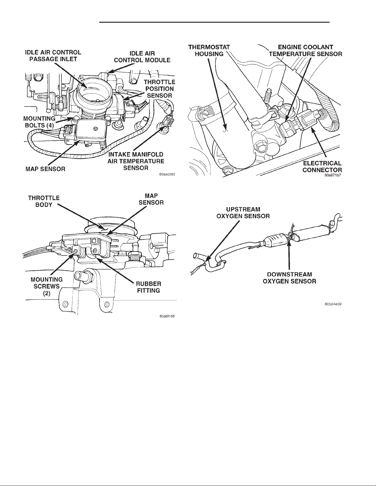
14 - 38 FUEL SYSTEM XJ
DIAGNOSIS AND TESTING (Continued)
Fig. 22 Sensor Locations—4.0L Engine
Fig. 23 Rubber L-Shaped Fitting—MAP Sensor-to-
Throttle Body
(20) Raise and support vehicle.
(21) Verify both oxygen sensor wire connectors are
firmly connected to sensors. Inspect sensors and connectors for damage (Fig. 25).
(22) Inspect for pinched or leaking fuel tubes.
Inspect for pinched, cracked or leaking fuel hoses.
(23) Inspect for exhaust system restrictions such
as pinched exhaust pipes, collapsed muffler or
plugged catalytic convertor.
(24) If equipped with automatic transmission, verify electrical harness is firmly connected to park/neutral switch. Refer to Automatic Transmission section
of Group 21.
(25) Verify electrical harness connector is firmly
connected to vehicle speed sensor (Fig. 26) or (Fig.
27).
Fig. 24 Engine Coolant Temperature Sensor—
Typical
Fig. 25 Location of Oxygen Sensors
(26) 2.5L 4–Cylinder Engine Only: Verify good
electrical connection at power steering pressure
switch (Fig. 28). This switch is not used with 4.0L
engines.
(27) Verify good electrical connections at fuel pump
module connector at front of fuel tank (Fig. 29).
(28) Verify good EVAP canister vent line connection at front of fuel tank (Fig. 29).
(29) Verify good fuel supply line connection at
front of fuel tank (Fig. 29).
(30) Inspect all fuel lines/hoses for cracks or leaks.
(31) Inspect transmission torque convertor housing
(automatic transmission) or clutch housing (manual
transmission) for damage to timing ring on drive
plate/flywheel.
(32) Verify battery cable and solenoid feed wire
connections to starter solenoid are tight and clean.
Inspect for chaffed wires or wires rubbing up against
other components.
Page 39
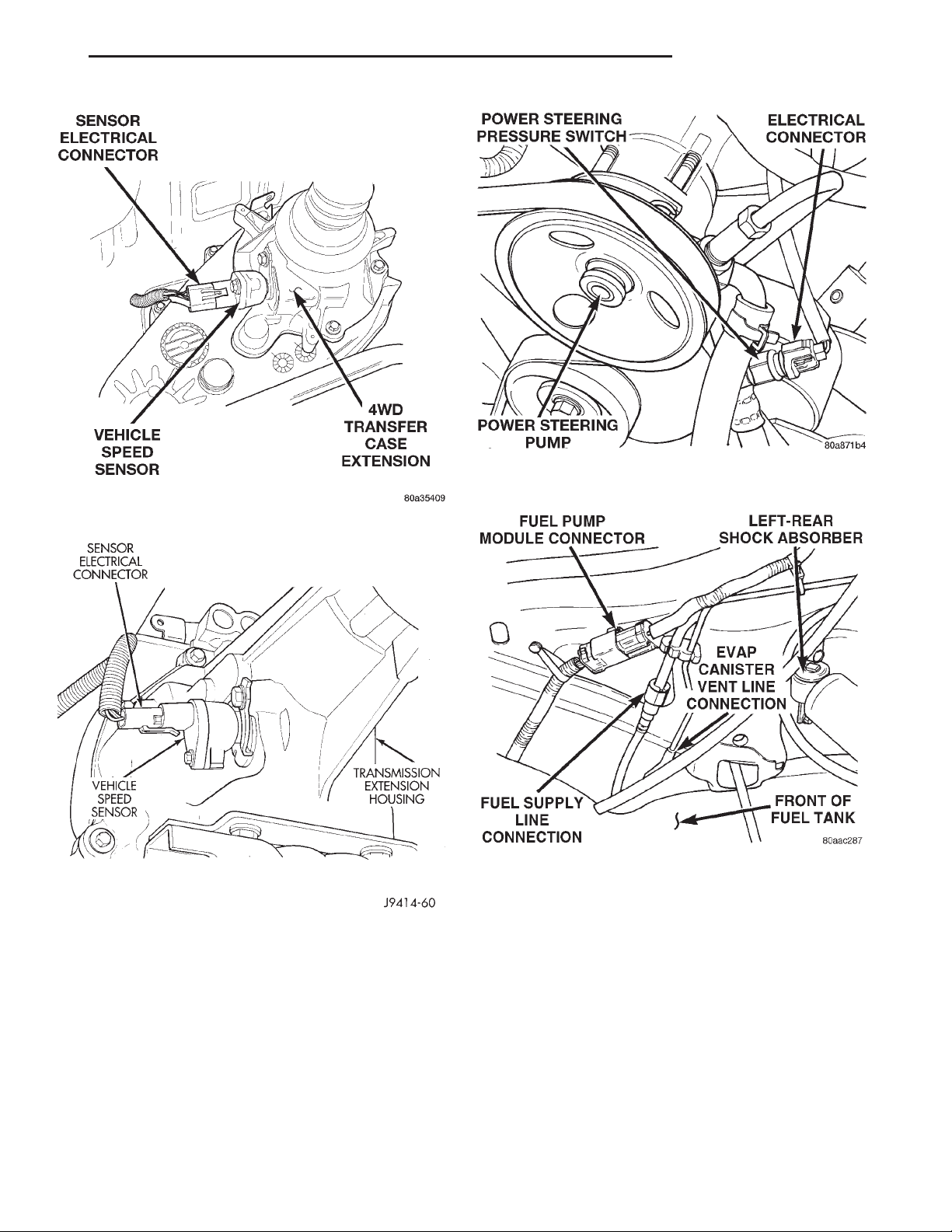
XJ FUEL SYSTEM 14 - 39
DIAGNOSIS AND TESTING (Continued)
Fig. 28 Power Steering Pressure Switch—2.5L
Engine
Fig. 26 Vehicle Speed Sensor—2WD
Fig. 27 Vehicle Speed Sensor—4WD
ASD AND FUEL PUMP RELAYS
The following description of operation and
tests apply only to the Automatic Shutdown
(ASD) and fuel pump relays. The terminals on the
bottom of each relay are numbered (Fig. 30) or (Fig.
31).
Fig. 29 Fuel Tank Connections at Front of Fuel Tank
OPERATION
• Terminal number 30 is connected to battery voltage. For both the ASD and fuel pump relays, terminal 30 is connected to battery voltage at all times.
• The PCM grounds the coil side of the relay
through terminal number 85.
• Terminal number 86 supplies voltage to the coil
side of the relay.
• When the PCM de-energizes the ASD and fuel
pump relays, terminal number 87A connects to terminal 30. This is the Off position. In the off position,
voltage is not supplied to the rest of the circuit. Terminal 87A is the center terminal on the relay.
Page 40
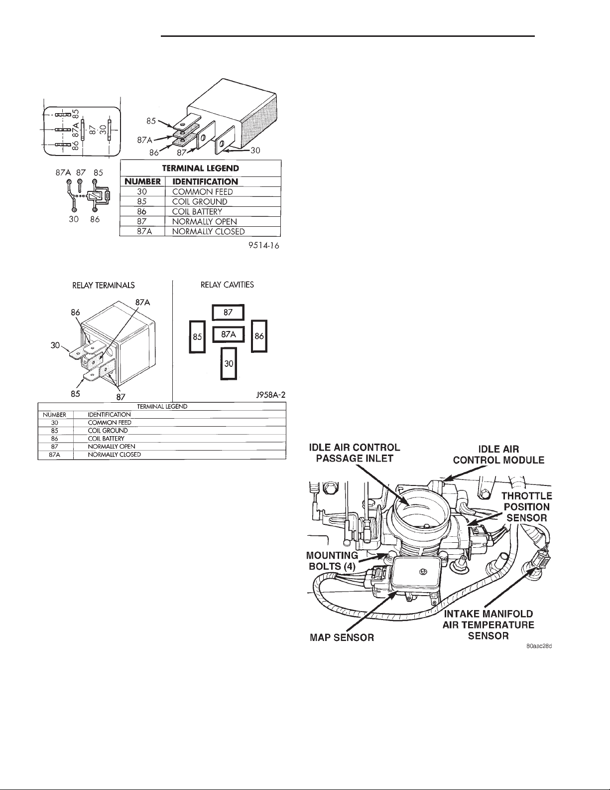
14 - 40 FUEL SYSTEM XJ
DIAGNOSIS AND TESTING (Continued)
of the jumper wire to the ground side of a 12 volt
power source.
(6) Connect one end of another jumper wire (16
gauge or smaller) to the power side of the 12 volt
power source. Do not attach the other end of the
jumper wire to the relay at this time.
WARNING: DO NOT ALLOW OHMMETER TO CONTACT TERMINALS 85 OR 86 DURING THIS TEST.
(7) Attach the other end of the jumper wire to
relay terminal 86. This activates the relay. The ohmmeter should now show continuity between relay terminals 87 and 30. The ohmmeter should not show
continuity between relay terminals 87A and 30.
(8) Disconnect jumper wires.
Fig. 30 ASD and Fuel Pump Relay Terminals
(9) Replace the relay if it did not pass the continuity and resistance tests. If the relay passed the tests,
it operates properly. Check the remainder of the ASD
and fuel pump relay circuits. Refer to the Wiring
Diagrams.
Fig. 31 ASD and Fuel Pump Relay Terminals
• When the PCM energizes the ASD and fuel
pump relays, terminal 87 connects to terminal 30.
This is the On position. Terminal 87 supplies voltage
to the rest of the circuit.
TESTING
The following procedure applies to the ASD and
fuel pump relays.
(1) Remove relay from connector before testing.
(2) With the relay removed from the vehicle, use
an ohmmeter to check the resistance between terminals 85 and 86. The resistance should be between 75
65 ohms.
(3) Connect the ohmmeter between terminals 30
and 87A. The ohmmeter should show continuity
between terminals 30 and 87A.
(4) Connect the ohmmeter between terminals 87
and 30. The ohmmeter should not show continuity at
this time.
(5) Connect one end of a jumper wire (16 gauge or
smaller) to relay terminal 85. Connect the other end
MANIFOLD ABSOLUTE PRESSURE (MAP) SENSOR TEST
To perform a complete test of MAP sensor (Fig. 32)
and its circuitry, refer to DRB scan tool and appropriate Powertrain Diagnostics Procedures manual. To
test the MAP sensor only, refer to the following:
(1) Inspect rubber L-shaped fitting from MAP sensor to throttle body (Fig. 33). Repair as necessary.
Fig. 32 Sensor Location (4.0L Engine Shown)
CAUTION: When testing the MAP sensor, be sure
that the harness wires are not damaged by the test
meter probes.
(2) Test MAP sensor output voltage at MAP sensor
connector between terminals A and B (Fig. 34). With
Page 41
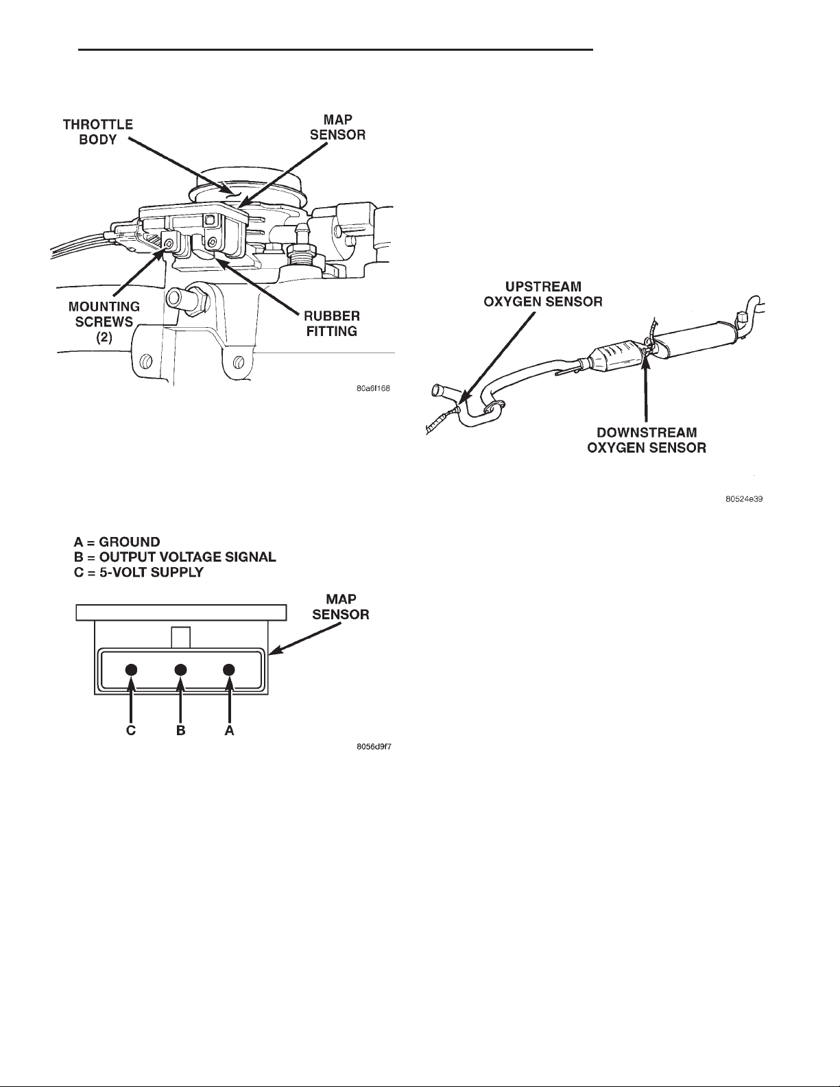
XJ FUEL SYSTEM 14 - 41
DIAGNOSIS AND TESTING (Continued)
OXYGEN (O2S) SENSORS
To perform a complete test of the O2S sensors and
their circuitry, refer to the DRB scan tool and appropriate Powertrain Diagnostics Procedures manual. To
test the O2S sensors only, refer to the following:
The upstream O2S sensor is located on the exhaust
downpipe (Fig. 35).
The downstream O2S sensor is located near the
outlet end of the catalytic converter (Fig. 35).
Fig. 33 Rubber L-Shaped Fitting—MAP Sensor-to-
Throttle Body
ignition switch ON and engine OFF, output voltage
should be 4-to-5 volts. The voltage should drop to 1.5to-2.1 volts with a hot, neutral idle speed condition.
Fig. 34 MAP Sensor Connector Terminals—Typical
(3) Test Powertrain Control Module (PCM) cavity
A-27 for same voltage described above to verify wire
harness condition. Repair as necessary.
(4) Test MAP sensor supply voltage at sensor connector between terminals A and C (Fig. 34) with ignition ON. The voltage should be approximately 5 volts
(60.5V). Five volts (60.5V) should also be at cavity
A-17 of the PCM wire harness connector. Repair or
replace wire harness as necessary.
(5) Test the MAP sensor ground circuit at sensor
connector terminal—A (Fig. 34) and PCM connector
A-4. Repair wire harness if necessary.
Refer to Group 8W, Wiring Diagrams for cavity
locations.
Fig. 35 Oxygen Sensor Location
Each O2S heating element can be tested with an
ohmmeter as follows:
Disconnect the O2S sensor connector. Connect the
ohmmeter test leads across the white wire terminals
of the sensor connector. Resistance should be
between 4.5 6.5 ohms and 7 ohms. Replace the sensor if the ohmmeter displays an infinity (open) reading.
ENGINE COOLANT TEMPERATURE SENSOR
To perform a complete test of the engine coolant
temperature sensor and its circuitry, refer to DRB
scan tool and appropriate Powertrain Diagnostics
Procedures manual. To test the sensor only, refer to
the following:
(1) Disconnect wire harness connector from coolant
temperature sensor (Fig. 36).
(2) Test the resistance of sensor with a high input
impedance (digital) volt-ohmmeter. Refer to SENSOR
RESISTANCE (OHMS)—COOLANT TEMPERATURE SENSOR/INTAKE AIR TEMPERATURE
SENSOR chart. The resistance (as measured across
sensor terminals) should be within range shown in
chart. If not, replace sensor.
(3) Test continuity of the wire harness between the
PCM wire harness connector and the coolant sensor
connector terminals. Refer to Group 8, Wiring for terminal/cavity locations. Repair the wire harness if an
open circuit is indicated.
Page 42
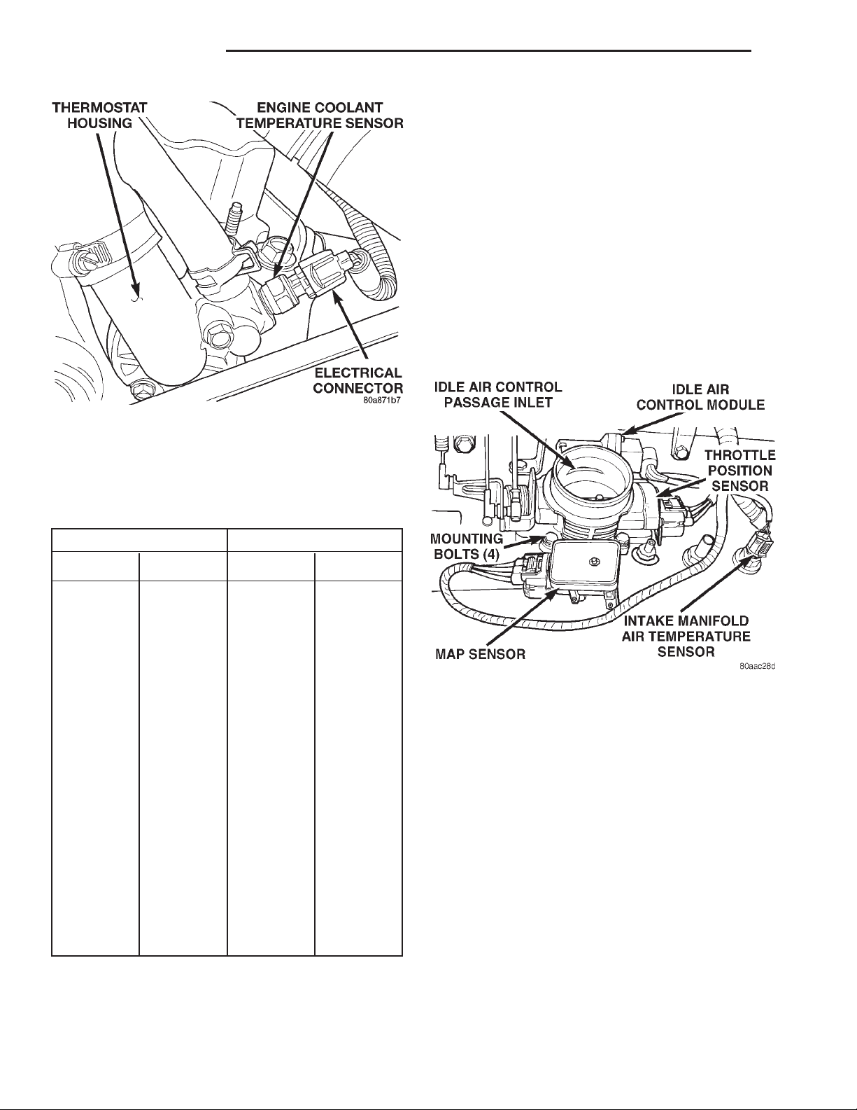
14 - 42 FUEL SYSTEM XJ
DIAGNOSIS AND TESTING (Continued)
IDLE AIR CONTROL (IAC) MOTOR
To perform a complete test of the IAC motor and
its circuitry, refer to DRB scan tool and appropriate
Powertrain Diagnostics Procedures manual.
INTAKE MANIFOLD AIR TEMPERATURE SENSOR
To perform a complete test of the intake manifold
air temperature sensor and its circuitry, refer to DRB
tester and appropriate Powertrain Diagnostics Procedures manual. To test the sensor only, refer to the
following:
(1) Disconnect wire harness connector from intake
manifold air temperature sensor (Fig. 37) or (Fig.
38).
Fig. 36 Engine Coolant Temperature Sensor—
Typical
SENSOR RESISTANCE (OHMS)—COOLANT
TEMPERATURE SENSOR/INTAKE AIR
TEMPERATURE SENSOR
TEMPERATURE RESISTANCE (OHMS)
°CEL. °FAHR. MIN. MAX.
-40 -40 291,490 381,710
-20 -4 85,850 108,390
-10 14 49,250 61,430
0 32 29,330 35,990
10 50 17,990 21,810
20 68 11,370 13,610
25 77 9,120 10,880
30 86 7,370 8,750
40 104 4,900 5,750
50 122 3,330 3,880
60 140 2,310 2,670
70 158 1,630 1,870
80 176 1,170 1,340
90 194 860 970
100 212 640 720
110 230 480 540
120 248 370 410
Fig. 37 Intake Manifold Air Temperature Sensor—
4.0L Engine
(2) Test the resistance of sensor with a high input
impedance (digital) volt-ohmmeter. Refer to SENSOR
RESISTANCE (OHMS)—COOLANT TEMPERATURE SENSOR/INTAKE AIR TEMPERATURE
SENSOR chart. The resistance (as measured across
sensor terminals) should be within range shown in
chart. If not, replace sensor.
(3) Test resistance of wire harness. Do this
between PCM wire harness connector A-15 and sensor connector terminal. Also check between PCM connector A-4 to sensor connector terminal. Repair wire
harness as necessary if resistance is greater than 1
ohm.
POWER STEERING PRESSURE SWITCH
2.5L 4–Cylinder Engine Only
This switch (Fig. 39) provides an input to the Powertrain Control Module (PCM). The input is provided
Page 43
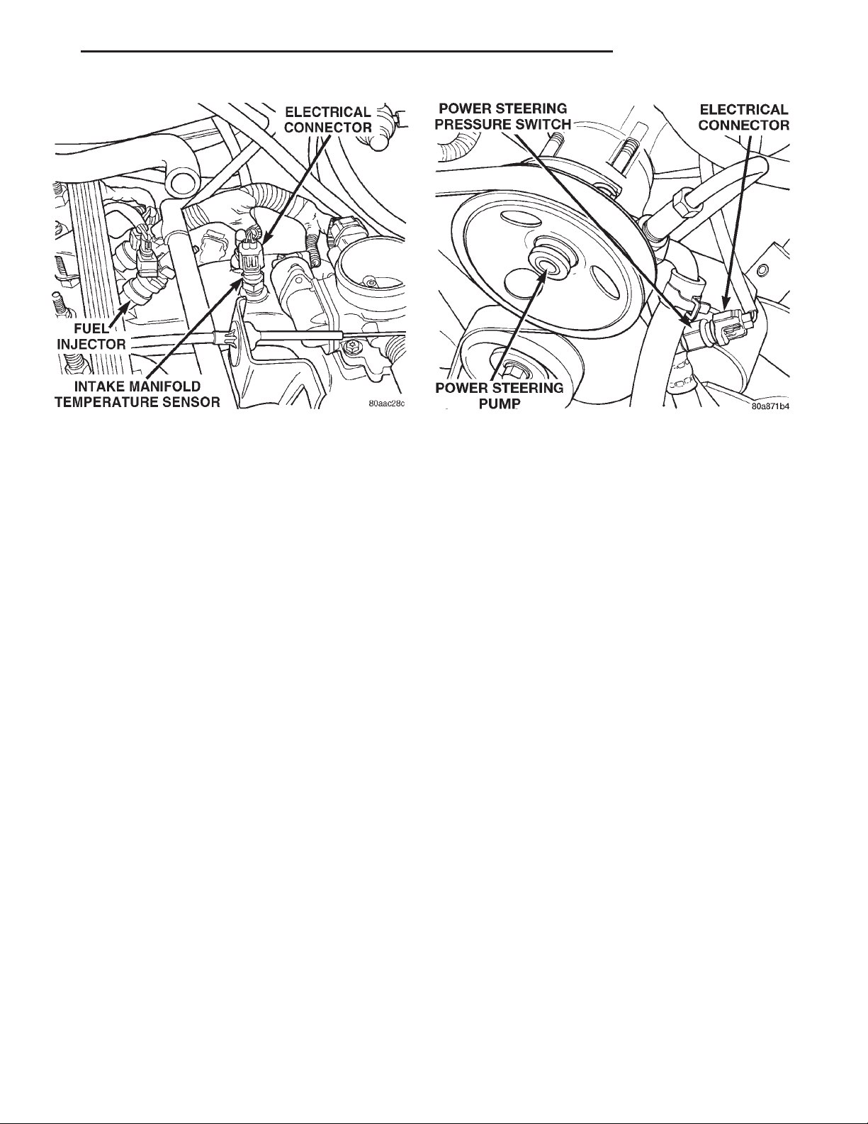
XJ FUEL SYSTEM 14 - 43
DIAGNOSIS AND TESTING (Continued)
Fig. 38 Intake Manifold Air Temperature Sensor—
2.5L Engine
during periods of high pump load and low engine
rpm; such as during parking maneuvers. The PCM
will then increase idle speed through the Idle Air
Control (IAC) motor. This is done to prevent the
engine from stalling under the increased load.
When steering pump pressure exceeds 3275 kPa 6
690 kPa (475 psi 6 100 psi), the normally closed
switch circuit will open and the PCM will increase
the engine idle speed.
When power steering pump pressure drops to
approximately 1379 kPa (200 psi), the switch circuit
will re-close and idle speed will return to normal.
To test switch:
(1) Disconnect electrical connector at switch.
(2) Connect a pair of jumper wires to switch terminals. Route and secure jumper wires away from fan
blades and fan belt.
(3) Connect an ohmmeter to jumper wires and
observe continuity. Circuit should be closed with
engine not running. If continuity is observed, switch
is OK. If switch circuit is open, replace switch.
(4) Start engine and observe ohmmeter. With
engine at idle speed, continuity should be observed
until steering wheel has been turned to left or right
position. Do not hold steering wheel in full left
or right position for more than a few seconds.
Damage to power steering pump may occur.
(5) If continuity is still observed after turning
wheel (circuit did not open) , replace switch.
VEHICLE SPEED SENSOR
To perform a complete test of the sensor and its
circuitry, refer to DRB scan tool and appropriate
Powertrain Diagnostics Procedures manual.
Fig. 39 Power Steering Pump Pressure Switch—2.5L
Engine
EXTENDED IDLE SWITCH TEST
OPTIONAL POLICE PACKAGE ONLY
The extended idle switch is used to raise engine
idle speed to approximately 1000 rpm when the
shifter is in either Park or Neutral position. A rockertype switch (extended idle switch) is mounted to
instrument panel. This switch is available only
with 4.0L engine when supplied with optional
police package.
The extended idle switch will control a ground circuit going to the powertrain control module (PCM).
When a ground signal (through the switch) has been
received at pin/cavity A-12 (circuit K78) of the PCM,
engine idle speed will increase.
(1) Bring engine to normal operating temperature
and turn extended idle switch to ON position. Engine
idle speed should now increase to approximately
1000 rpm when shifter is in either Park or Neutral
position.
(2) If idle speed does not increase, unplug 4–way
electrical connector from switch.
(3) Check circuit Z1L for ground. Ground should
be present at all times. If not, repair open circuit to
ground. Refer to Group 8W, Wiring Diagrams for circuit and wiring information.
(4) If ground is present at Z1L, check continuity of
switch between circuits Z1L and K78. If continuity is
not present, replace switch. If switch is OK proceed
to next step.
(5) With 4–way electrical connector still unplugged
from switch, apply a good ground to circuit K78.
Engine idle speed should increase. If not, proceed to
next step.
Page 44
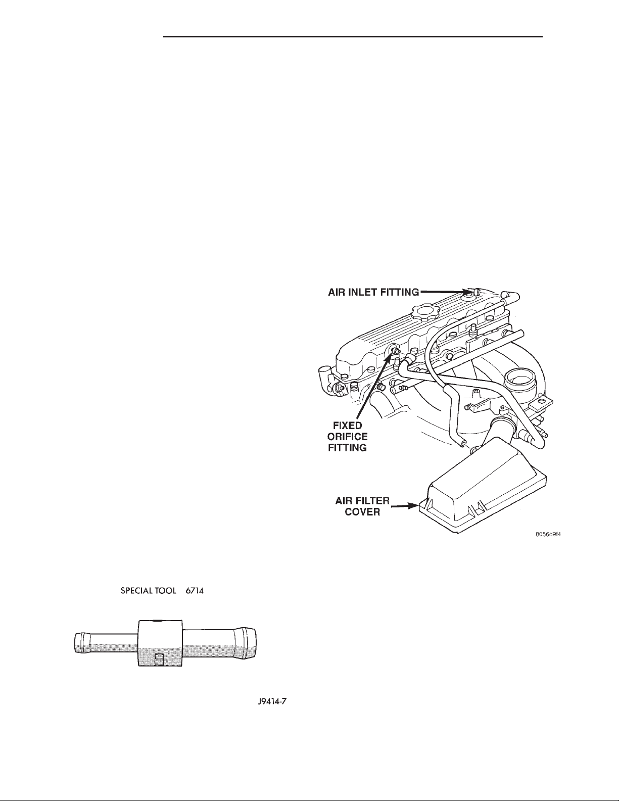
14 - 44 FUEL SYSTEM XJ
DIAGNOSIS AND TESTING (Continued)
(6) Ground pin/cavity A-12 directly at PCM using a
small paper clip. Be careful not to damage wiring
with paper clip. If engine idle speed increases, it can
be assumed that PCM is functioning correctly. Repair
open circuit in circuit K78. If engine idle speed will
not increase after applying a ground to pin/cavity
A-12 (circuit K78) directly at PCM, replace PCM.
THROTTLE POSITION SENSOR (TPS)
To perform a complete test of the TPS (Fig. 37) and
its circuitry, refer to the DRB scan tool and appropriate Powertrain Diagnostics Procedures manual. To
test the TPS only, refer to the following:
The TPS can be tested with a digital voltmeter.
The center terminal of the TPS is the output terminal.
With the ignition key in the ON position, check the
TPS output voltage at the center terminal wire of the
connector. Check this at idle (throttle plate closed)
and at Wide Open Throttle (WOT). At idle, TPS output voltage should be greater than .26 volts but less
than .95 volts. At wide open throttle, TPS output
voltage must be less than 4.49 volts. The output voltage should increase gradually as the throttle plate is
slowly opened from idle to WOT.
(1) Start the engine and bring to operating temperature. Be sure all accessories are off before performing this test.
(2) Shut off engine and remove air duct at throttle
body.
(3) 2.5L 4–Cylinder Engine: Near front/top of
valve cover, disconnect CCV tube at fixed orifice fitting (Fig. 41). Insert Special Tool 6714 into end of
disconnected CCV tube (insert either end of tool into
tube). Let tool and tube hang disconnected at side of
engine.
(4) 4.0L 6–Cylinder Engine: Disconnect CCV
tube (Fig. 42) at intake manifold fitting. Attach a
short piece of rubber hose to special tool 6714 (insert
rubber hose to either end of tool). Install rubber hose/
tool to intake manifold fitting. Let CCV tube hang
disconnected at side of engine.
THROTTLE BODY MINIMUM AIR FLOW CHECK PROCEDURE
The following test procedure has been developed to
check throttle body calibrations for correct idle conditions. The procedure should be used to diagnose the
throttle body for conditions that may cause idle problems. This procedure should be used only after
normal diagnostic procedures have failed to
produce results that indicate a throttle body
related problem. Be sure to check for proper
operation of the idle air control motor before
performing this test.
A special fixed orifice tool (number 6714) (Fig. 40)
must be used for the following test. This tool has a
fixed internal diameter of 0.185”.
Fig. 40 6714 Fixed Orifice Tool
Fig. 41 Install Orifice Tool 2.5L 4–Cylinder Engine
(5) Connect DRB scan tool to 16–way data link
connector. This connector is located at lower edge of
instrument panel near steering column. Refer to
appropriate Powertrain Diagnostic Procedures service manual for DRB operation.
(6) Start engine and allow to warm up.
(7) Using the DRB scan tool, scroll through menus
as follows: select—Stand Alone DRB III, select 1999
Diagnostics, select—Engine, select—System Test,
select—Minimum Air Flow.
(8) The DRB scan tool will count down to stabilize
idle rpm and display minimum air flow idle rpm. The
idle rpm should be between 500 and 900 rpm. If idle
speed is outside these specifications, replace throttle
body. Refer to Throttle Body Removal/Installation.
(9) Disconnect DRB scan tool from vehicle.
Page 45
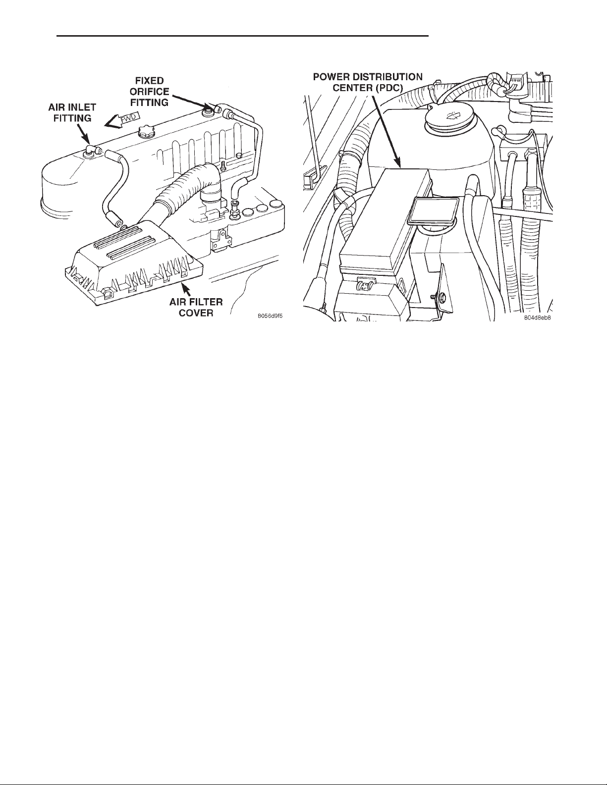
XJ FUEL SYSTEM 14 - 45
DIAGNOSIS AND TESTING (Continued)
Fig. 42 Install Orifice Tool 4.0L 6–Cylinder Engine
(10) Remove orifice tool and connect CCV tube to
engine.
(11) Install air duct to throttle body.
REMOVAL AND INSTALLATION
AUTOMATIC SHUTDOWN (ASD) RELAY
The ASD relay is located in the Power Distribution
Center (PDC) (Fig. 43). Refer to label on PDC cover
for relay location.
REMOVAL
(1) Remove PDC cover.
(2) Remove relay from PDC.
(3) Check condition of relay terminals and PDC
connector terminals for damage or corrosion. Repair
if necessary before installing relay.
(4) Check for pin height (pin height should be the
same for all terminals within the PDC connector).
Repair if necessary before installing relay.
INSTALLATION
(1) Install relay to PDC.
(2) Install cover to PDC.
FUEL PUMP RELAY
The fuel pump relay is located in the Power Distribution Center (PDC) (Fig. 43). Refer to label on PDC
cover for relay location.
Fig. 43 Power Distribution Center (PDC)
REMOVAL
(1) Remove PDC cover.
(2) Remove relay from PDC.
(3) Check condition of relay terminals and PDC
connector terminals for damage or corrosion. Repair
if necessary before installing relay.
(4) Check for pin height (pin height should be the
same for all terminals within the PDC connector).
Repair if necessary before installing relay.
INSTALLATION
(1) Install relay to PDC.
(2) Install cover to PDC.
THROTTLE BODY
A (factory adjusted) set screw is used to mechanically limit the position of the throttle body throttle
plate. Never attempt to adjust the engine idle
speed using this screw. All idle speed functions are
controlled by the Powertrain Control Module (PCM).
REMOVAL
(1) Remove air cleaner tube at throttle body.
(2) Disconnect throttle body electrical connectors
at MAP sensor, IAC motor and TPS (Fig. 44) or (Fig.
45).
(3) Remove all control cables from throttle body
(lever) arm. Refer to the Accelerator Pedal and Throttle Cable section of this group for additional information.
(4) Remove four throttle body mounting bolts.
(5) Remove throttle body from intake manifold.
Page 46
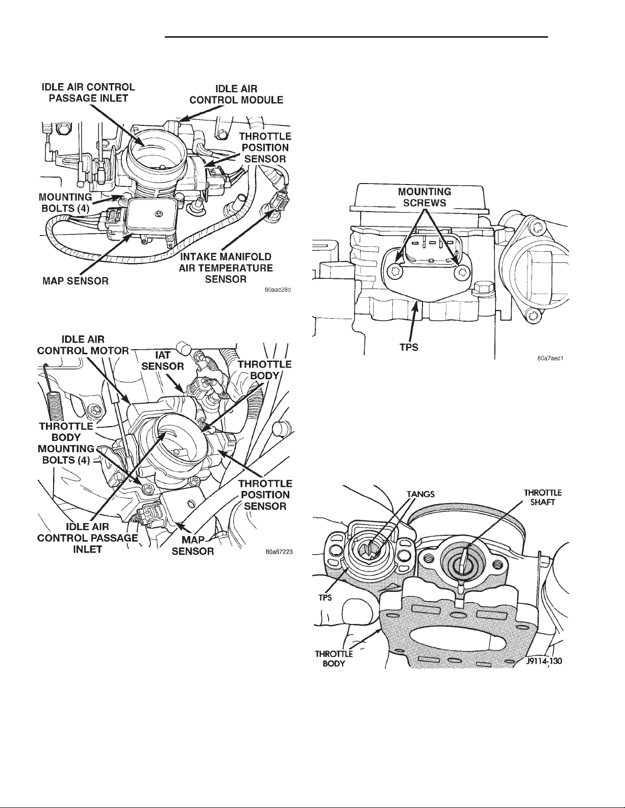
14 - 46 FUEL SYSTEM XJ
REMOVAL AND INSTALLATION (Continued)
THROTTLE POSITION SENSOR (TPS)
The TPS is mounted to the throttle body (Fig. 44)
or (Fig. 45).
REMOVAL
(1) Disconnect TPS electrical connector.
(2) Remove TPS mounting screws (Fig. 46).
(3) Remove TPS.
Fig. 44 Throttle Body and Sensor Locations—4.0L
Engine
Fig. 45 Throttle Body and Sensor Locations—2.5L
Engine
(6) Discard old throttle body-to-intake manifold
gasket.
INSTALLATION
(1) Clean mating surfaces of throttle body and
intake manifold.
(2) Install new throttle body-to-intake manifold
gasket.
(3) Install throttle body to intake manifold.
(4) Install four mounting bolts. Tighten bolts to 11
N·m (100 in. lbs.) torque.
(5) Install control cables.
(6) Install electrical connectors.
(7) Install air cleaner at throttle body.
Fig. 46 TPS Mounting Screws
INSTALLATION
The throttle shaft end of the throttle body slides
into a socket in the TPS (Fig. 47). The TPS must be
installed so that it can be rotated a few degrees. (If
the sensor will not rotate, install the sensor with the
throttle shaft on the other side of the socket tangs).
The TPS will be under slight tension when rotated.
Fig. 47 Throttle Position Sensor—Installation
(1) Install TPS and retaining screws.
(2) Tighten screws to 7 N·m (60 in. lbs.) torque.
(3) Connect TPS electrical connector to TPS.
(4) Manually operate throttle (by hand) to check
for any TPS binding before starting engine.
Page 47
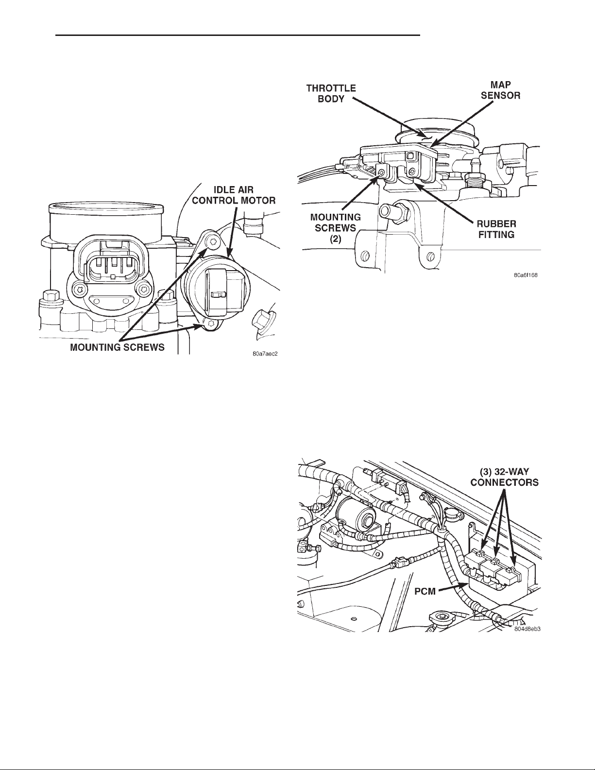
XJ FUEL SYSTEM 14 - 47
REMOVAL AND INSTALLATION (Continued)
IDLE AIR CONTROL (IAC) MOTOR
The IAC motor is located on the side of the throttle
body (Fig. 44) or (Fig. 45).
REMOVAL
(1) Remove air cleaner tube at throttle body.
(2) Disconnect electrical connector from IAC motor.
(3) Remove two mounting bolts (screws) (Fig. 48).
(4) Remove IAC motor from throttle body.
Fig. 49 MAP Sensor Mounting
(3) Install MAP sensor mounting bolts (screws).
Tighten screws to 3 N·m (25 in. lbs.) torque.
(4) Install air cleaner intake tube.
Fig. 48 Mounting Bolts (Screws)—IAC Motor
INSTALLATION
(1) Install IAC motor to throttle body.
(2) Install and tighten two mounting bolts (screws)
to 7 N·m (60 in. lbs.) torque.
(3) Install electrical connector.
(4) Install air cleaner tube to throttle body.
MANIFOLD ABSOLUTE PRESSURE (MAP) SENSOR
The MAP sensor is mounted to the side of the
throttle body (Fig. 44) or (Fig. 45). An L-shaped rubber fitting is used to connect the MAP sensor to
throttle body (Fig. 49).
REMOVAL
(1) Remove air cleaner intake tube at throttle
body.
(2) Remove two MAP sensor mounting bolts
(screws) (Fig. 49).
(3) While removing MAP sensor, slide the rubber
L-shaped fitting (Fig. 49) from throttle body.
(4) Remove rubber L-shaped fitting from MAP sensor.
INSTALLATION
(1) Install rubber L-shaped fitting to MAP sensor.
(2) Position sensor to throttle body while guiding
rubber fitting over throttle body vacuum nipple.
DUTY CYCLE EVAP CANISTER PURGE SOLENOID
Refer to Group 25, Emission Control System for
removal/installation procedures.
POWERTRAIN CONTROL MODULE (PCM)
The PCM is located in the engine compartment
next to the air cleaner assembly (Fig. 50).
Fig. 50 PCM Location
REMOVAL
To avoid possible voltage spike damage to the
PCM, ignition key must be off, and negative battery
cable must be disconnected before unplugging PCM
connectors.
(1) Disconnect negative battery cable at battery.
Page 48
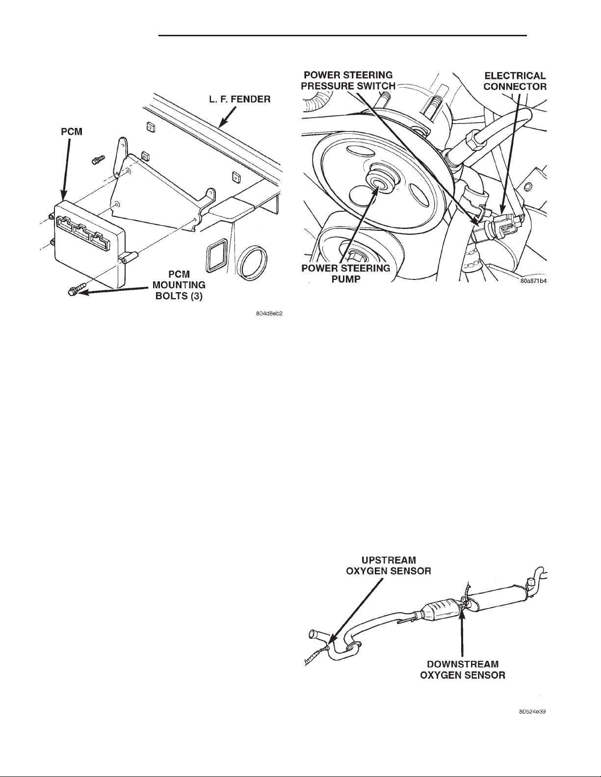
14 - 48 FUEL SYSTEM XJ
REMOVAL AND INSTALLATION (Continued)
Fig. 52 Power Steering Pressure Switch
(2) Place a small container or shop towel beneath
Fig. 51 PCM Mounting
(2) Remove cover over electrical connectors. Cover
snaps onto PCM.
(3) Carefully unplug the three 32–way connectors
(Fig. 51) from PCM.
(4) Remove three PCM mounting bolts and remove
PCM from vehicle.
INSTALLATION
(1) Install PCM and mounting bolts to vehicle.
(2) Tighten bolts to 4 N·m (35 in. lbs.).
(3) Check pin connectors in the PCM and the three
32–way connectors for corrosion or damage. Also, the
pin heights in connectors should all be same. Repair
as necessary before installing connectors.
(4) Install three 32–way connectors.
(5) Install cover over electrical connectors. Cover
snaps onto PCM.
(6) Install battery cable.
(7) Use the DRB scan tool to reprogram new PCM
with vehicles original Identification Number (VIN)
and original vehicle mileage.
switch to collect any excess fluid.
(3) Remove switch. Use back-up wrench on power
steering line to prevent line bending.
INSTALLATION
(1) Install power steering switch into power steer-
ing line.
(2) Tighten to 14–22 N·m (124–195 in. lbs.) torque.
(3) Connect electrical connector to switch.
(4) Check power steering fluid and add as neces-
sary.
(5) Start engine and again check power steering
fluid. Add fluid if necessary.
OXYGEN SENSOR
The upstream O2S sensor is located in exhaust
downpipe. The downstream sensor is located near
outlet end of catalytic converter. Refer to (Fig. 53).
POWER STEERING PRESSURE SWITCH—2.5L
ENGINE
This switch is not used with 4.0L six-cylinder
engines.
The power steering pressure switch is installed in
the power steering high-pressure hose (Fig. 52).
REMOVAL
(1) Disconnect electrical connector from power
steering pressure switch.
Fig. 53 Oxygen Sensor Locations
Page 49
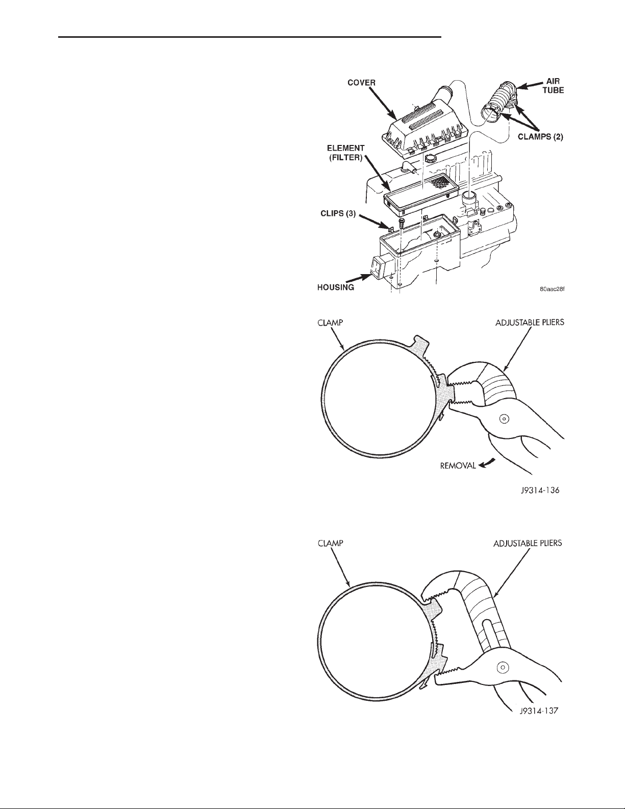
XJ FUEL SYSTEM 14 - 49
REMOVAL AND INSTALLATION (Continued)
REMOVAL
WARNING: THE EXHAUST MANIFOLD, EXHAUST
PIPES AND CATALYTIC CONVERTER BECOME
VERY HOT DURING ENGINE OPERATION. ALLOW
ENGINE TO COOL BEFORE REMOVING OXYGEN
SENSOR.
(1) Raise and support vehicle.
(2) Disconnect wire connector from O2S sensor.
CAUTION: When disconnecting sensor electrical
connector, do not pull directly on wire going into
sensor.
(3) Remove O2S sensor. Snap-On oxygen sensor
wrench (number YA 8875) may be used for removal
and installation.
INSTALLATION
Threads of new oxygen sensors are factory coated
with anti-seize compound to aid in removal. DO
NOT add any additional anti-seize compound to
threads of a new oxygen sensor.
(1) Install O2S sensor. Tighten to 30 N·m (22 ft.
lbs.) torque.
(2) Connect O2S sensor wire connector.
(3) Lower vehicle.
AIR CLEANER ELEMENT (FILTER)
REMOVAL
(1) Unlock air tube clamp (Fig. 54) at air cleaner
cover. To unlock clamp, attach adjustable pliers to
clamp and rotate pliers as shown in (Fig. 55).
(2) Remove air tube at cover.
(3) Pry back three clips retaining air cleaner cover
to air cleaner housing.
(4) Remove housing cover and remove air cleaner
element.
(5) Clean inside of housing before replacing element.
Fig. 54 Air Cleaner Housing and Element (Filter)
Fig. 55 Clamp Removal
INSTALLATION
(1) Install air cleaner element into housing.
(2) Install air cleaner cover to housing (three
clips). Be sure cover is properly seated to air cleaner
housing.
(3) Install air tube and clamp to cover. Compress
clamp snugly with adjustable pliers as shown in (Fig.
56).
Fig. 56 Clamp Installation
Page 50
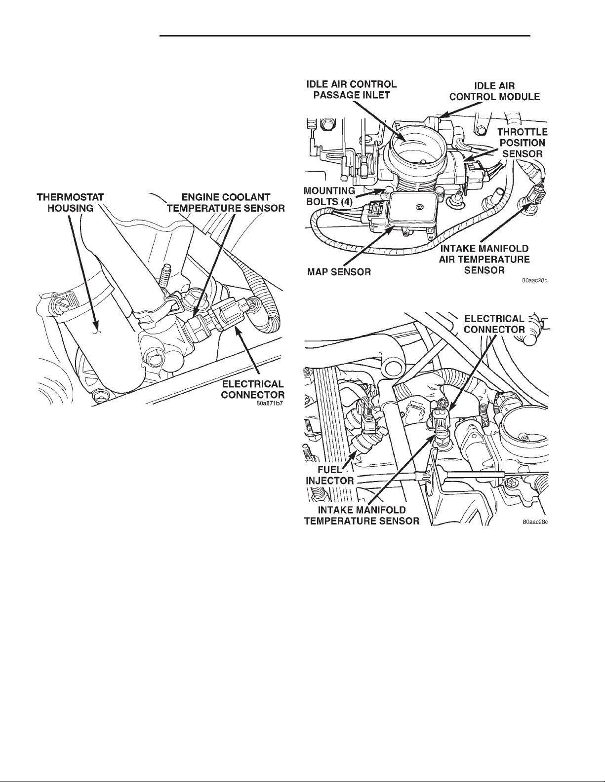
14 - 50 FUEL SYSTEM XJ
REMOVAL AND INSTALLATION (Continued)
ENGINE COOLANT TEMPERATURE SENSOR
WARNING: HOT, PRESSURIZED COOLANT CAN
CAUSE INJURY BY SCALDING. COOLING SYSTEM
MUST BE PARTIALLY DRAINED BEFORE REMOVING THE COOLANT TEMPERATURE SENSOR.
REFER TO GROUP 7, COOLING.
The coolant temperature sensor is installed in the
thermostat housing (Fig. 57).
Fig. 58 IAT Sensor Location—4.0L Engine
Fig. 57 Engine Coolant Temperature Sensor—
Typical
REMOVAL
(1) Partially drain cooling system until coolant
level is below cylinder head. Observe the WARN-
INGS in Group 7, Cooling.
(2) Disconnect coolant temperature sensor wire
connector.
(3) Remove sensor from thermostat housing.
INSTALLATION
(1) Apply sealant to sensor threads (new replacement sensors will have sealant already applied).
(2) Install coolant temperature sensor into thermostat housing. Tighten to 11 N·m (8 ft. lbs.) torque.
(3) Connect wire connector.
(4) Fill cooling system. Refer to Group 7, Cooling
System.
INTAKE MANIFOLD AIR TEMPERATURE SENSOR
The intake manifold air temperature (IAT) sensor
is installed into intake manifold plenum near throttle
body (Fig. 58) or (Fig. 59).
Fig. 59 IAT Sensor Location—2.5L Engine
REMOVAL
(1) Disconnect electrical connector from IAT sen-
sor.
(2) Remove sensor from intake manifold.
INSTALLATION
(1) Install IAT sensor into intake manifold.
Tighten sensor to 28 N·m (20 ft. lbs.) torque.
(2) Connect electrical connector to sensor.
VEHICLE SPEED SENSOR
The vehicle speed sensor is located on the speedometer pinion gear adapter (Fig. 60) or (Fig. 61). The
pinion gear adapter is located on the extension housing of transmission (drivers side).
Page 51
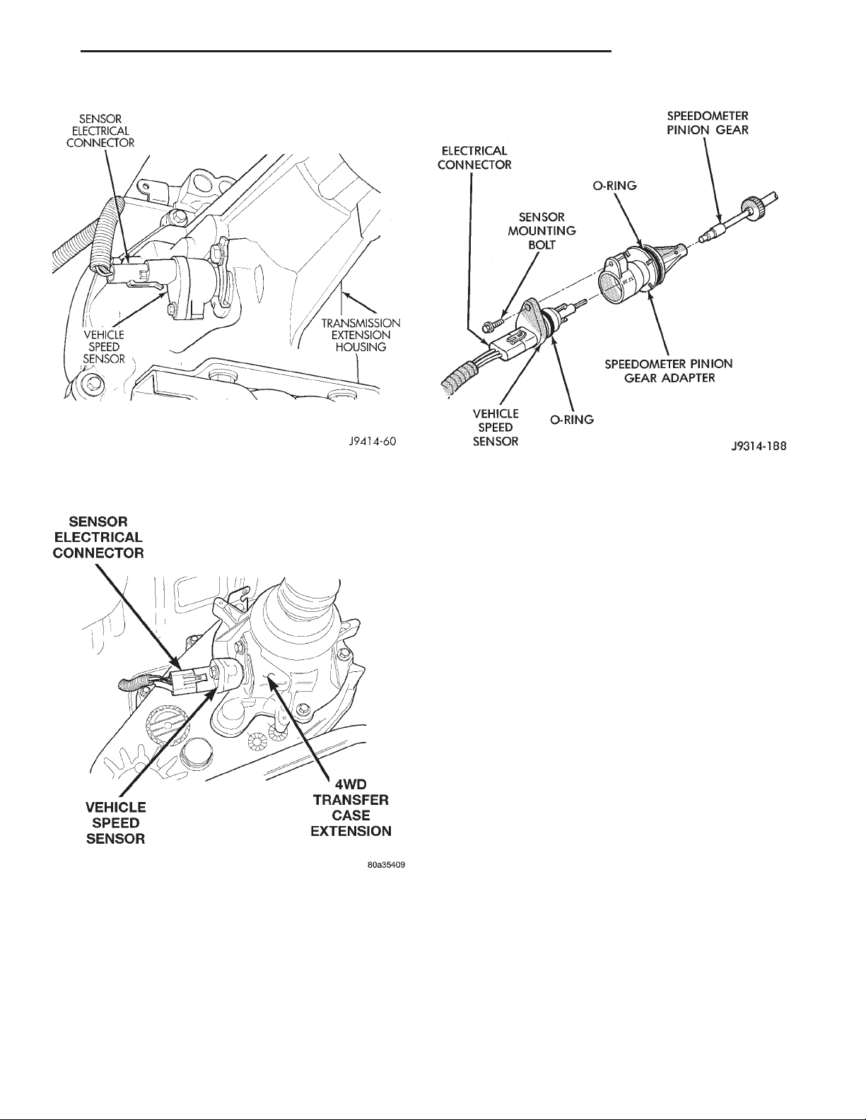
XJ FUEL SYSTEM 14 - 51
REMOVAL AND INSTALLATION (Continued)
Fig. 62 Sensor Removal/Installation
Fig. 60 Vehicle Speed Sensor Location—2WD—
Typical
INSTALLATION
(1) Clean inside of speedometer pinion gear
adapter before installing speed sensor.
(2) Install sensor into speedometer gear adapter
and install mounting bolt. Before tightening bolt,
verify speed sensor is fully seated (mounted
flush) to speedometer pinion gear adapter.
(3) Tighten sensor mounting bolt to 2.2 N·m (20 in.
lbs.) torque.
(4) Connect electrical connector to sensor.
Fig. 61 Vehicle Speed Sensor Location—4WD—
Typical
REMOVAL
(1) Raise and support vehicle.
(2) Disconnect electrical connector from sensor.
(3) Remove sensor mounting bolt (Fig. 62).
(4) Remove sensor (pull straight out) from speedometer pinion gear adapter (Fig. 62). Do not remove
gear adapter from transmission.
SPECIFICATIONS
TORQUE CHART
DESCRIPTION TORQUE
Air Cleaner Housing Mount. Bolts .........8N·m
(71 in. lbs.)
Engine Coolant Temperature Sensor ......11N·m
(96 in. lbs.)
IAC Motor-To-Throttle Body Bolts .........7N·m
(60 in. lbs.)
Intake Manifold Air Temp. Sensor ........28N·m
(20 ft. lbs.)
MAP Sensor Mounting Screws . . 3 N·m (25 in. lbs.)
Oxygen Sensor ..............30N·m(22ft.lbs.)
PCM Mounting Screws ........4N·m(35in.lbs.)
Power Steering Pressure Switch .......14–22 N·m
(124–195 in. lbs.)
Throttle Body Mounting Bolts . 11 N·m (100 in. lbs.)
Throttle Position Sensor Mounting Screws . . 7 N·m
(60 in. lbs.)
Page 52

14 - 52 FUEL SYSTEM XJ
SPECIFICATIONS (Continued)
DESCRIPTION TORQUE
Vehicle Speed Sensor Mounting Bolt ......2.2N·m
(20 in. lbs.)
SPECIAL TOOLS
FUEL SYSTEM
O2S (Oxygen Sensor) Remover/Installer—C-4907
Spanner Wrench, Fuel Pump Module Locknut—6856
Adapters, Fuel Pressure Test—6539 and/or 6631
Fitting, Air Metering—6714
Test Kit, Fuel Pressure—5069
Test Kit, Fuel Pressure—C-4799-B
Fuel Line Removal Tool—6782
 Loading...