

Page 1

XJ FRAME AND BUMPERS 13 - 1
FRAME AND BUMPERS
CONTENTS
page page
BUMPERS ............................... 1 FRAME ................................. 5
BUMPERS
INDEX
page page
REMOVAL AND INSTALLATION
FRONT BUMPER ......................... 1
FRONT BUMPER END CAP ................. 1
FRONT TOW HOOK ....................... 2
REMOVAL AND INSTALLATION
FRONT BUMPER END CAP
REMOVAL
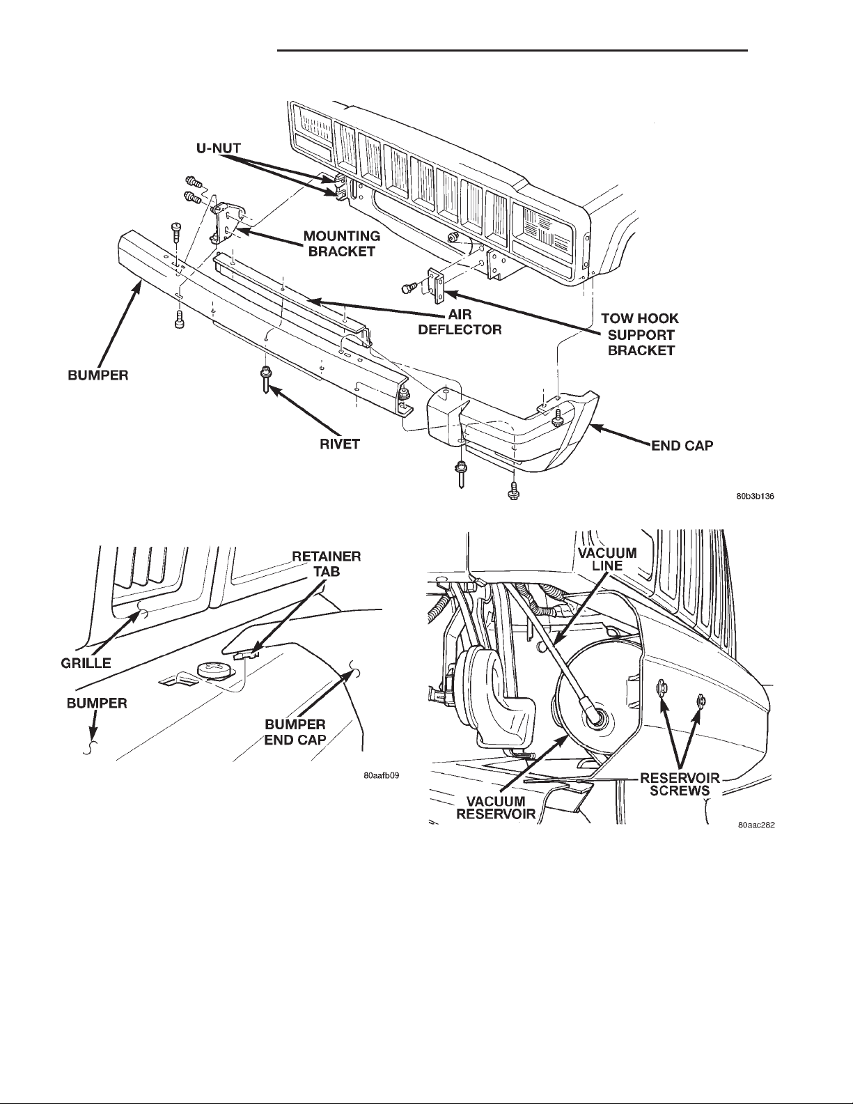
(1) Remove the rivet attaching the end cap to the
air deflector.
(2) Remove the bolts and nuts attaching the end
cap to the bumper (Fig. 1).
(3) Pull back the wheelhouse liner and remove the
screws attaching the end cap to the front fender.
(4) Lifting the end cap from the bottom, tilt
slightly upward and slide it outward to disengage the
retainer tab from the bumper (Fig. 2).
(5) Separate the end cap from the bumper.
INSTALLATION
(1) Position the end cap on the bumper and engage
the retaining tab.
(2) Install the screws attaching the end cap to the
front fender.
(3) Install the bolts attaching the end cap to the
bumper. Tighten the nut to 9 N·m (7 ft. lbs.) torque.
(4) Install the rivet attaching the end cap to air
deflector.
REAR BUMPER .......................... 3
REAR BUMPER END CAP .................. 2
REAR TOW HOOK ........................ 4
FRONT BUMPER
REMOVAL
(1) Remove bumper end caps.
(2) If equipped, disengage fog lamp wire harness
connectors.
(3) Disconnect vacuum line from reservoir (Fig. 3).
(4) Remove Torx-head bolts that attach bumper to
mounting brackets (Fig. 1).
(5) Remove bumper from vehicle.
(6) If necessary, remove bolts attaching bumper
mounting brackets to frame.
INSTALLATION
(1) If removed, install bolts attaching bumper
mounting brackets to frame. Tighten bolts to 55 N·m
(41 ft. lbs.) torque.
(2) Position bumper on front of vehicle.
(3) Install Torx-head bolts that attach bumper to
mounting brackets. Tighten bolts to 55 N·m (41 ft.
lbs.) torque.
(4) Connect vacuum line to reservoir.
(5) If equipped, engage fog lamp wire harness connectors.
(6) Install bumper end caps.
Page 2
13 - 2 FRAME AND BUMPERS XJ
REMOVAL AND INSTALLATION (Continued)
Fig. 1 Front Bumper
Fig. 2 Bumper End Cap
FRONT TOW HOOK
REMOVAL
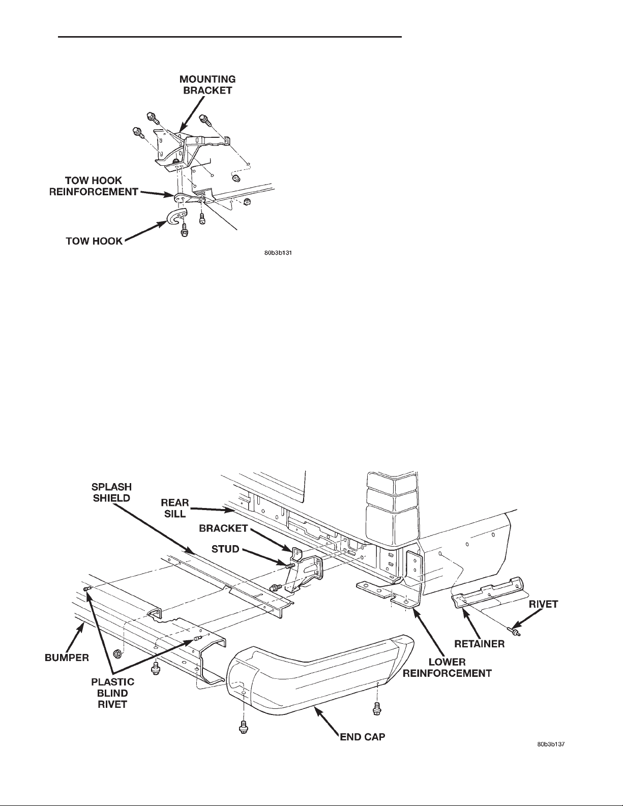
(1) Remove bolts attaching tow hook to tow hook
reinforcement (Fig. 4).
(2) Separate tow hook from reinforcement.
(3) If necessary, remove bolt attaching tow hook
reinforcement to frame.
Fig. 3 Vacuum Reservoir
(3) Install bolts attaching tow hook to tow hook
reinforcement. Tighten bolts to 100 N·m (74 ft. lbs.)
torque.
REAR BUMPER END CAP
INSTALLATION
(1) If removed, install bolt attaching tow hook
reinforcement to frame. Tighten bolt to 30 N·m (22 ft.
lbs.) torque.
(2) Position tow hook on reinforcement.
REMOVAL
(1) Remove the bolts and nuts attaching the
underside of the end cap to the bumper (Fig. 5).
(2) Remove the screw attaching the front of the
end cap to the underside of the quarter panel.
Page 3
XJ FRAME AND BUMPERS 13 - 3
REMOVAL AND INSTALLATION (Continued)
(4) Install the bolts and nuts attaching the under-
side of the end cap to the bumper.
REAR BUMPER
REMOVAL
(1) For vehicles equipped with a trailer hitch,
remove hitch before removing bumper. If necessary,
refer to removal procedure within Group 13, Frame
and Bumpers.
(2) Remove bumper end caps.
(3) Remove upper nuts that attach bumper to
bumper support brackets (Fig. 5).
(4) Remove lower bolts that attach bumper to
bumper support brackets.
(5) Remove bumper from vehicle.
Fig. 4 Front Tow Hook
(3) Lift the end cap slightly upward and slide it
rearward to release it from the retainer.
(4) Separate the end cap from the vehicle.
INSTALLATION
(1) Position the end cap on the rear of the retainer
and the outer edge of the bumper.
(2) Slide the end cap forward onto the retainer.
Ensure the end cap overlaps the lip of the rear
wheelhouse liner.
(3) Install the screw attaching the front of the end
cap to the underside of the quarter panel.
(6) If necessary, remove bumper support brackets
from the rear sill.
INSTALLATION
(1) If removed, install bumper support brackets on
the rear sill. Tighten bolts to 55 N·m (41 ft. lbs.)
torque.
(2) Position bumper on support brackets.
(3) Install bolts that attach bumper to bumper
support brackets. Tighten nuts to 55 N·m (41 ft. lbs.)
torque.
(4) Install bumper end caps.
(5) If removed, install trailer hitch.
Fig. 5 Rear Bumper
Page 4
13 - 4 FRAME AND BUMPERS XJ
REMOVAL AND INSTALLATION (Continued)
REAR TOW HOOK
REMOVAL
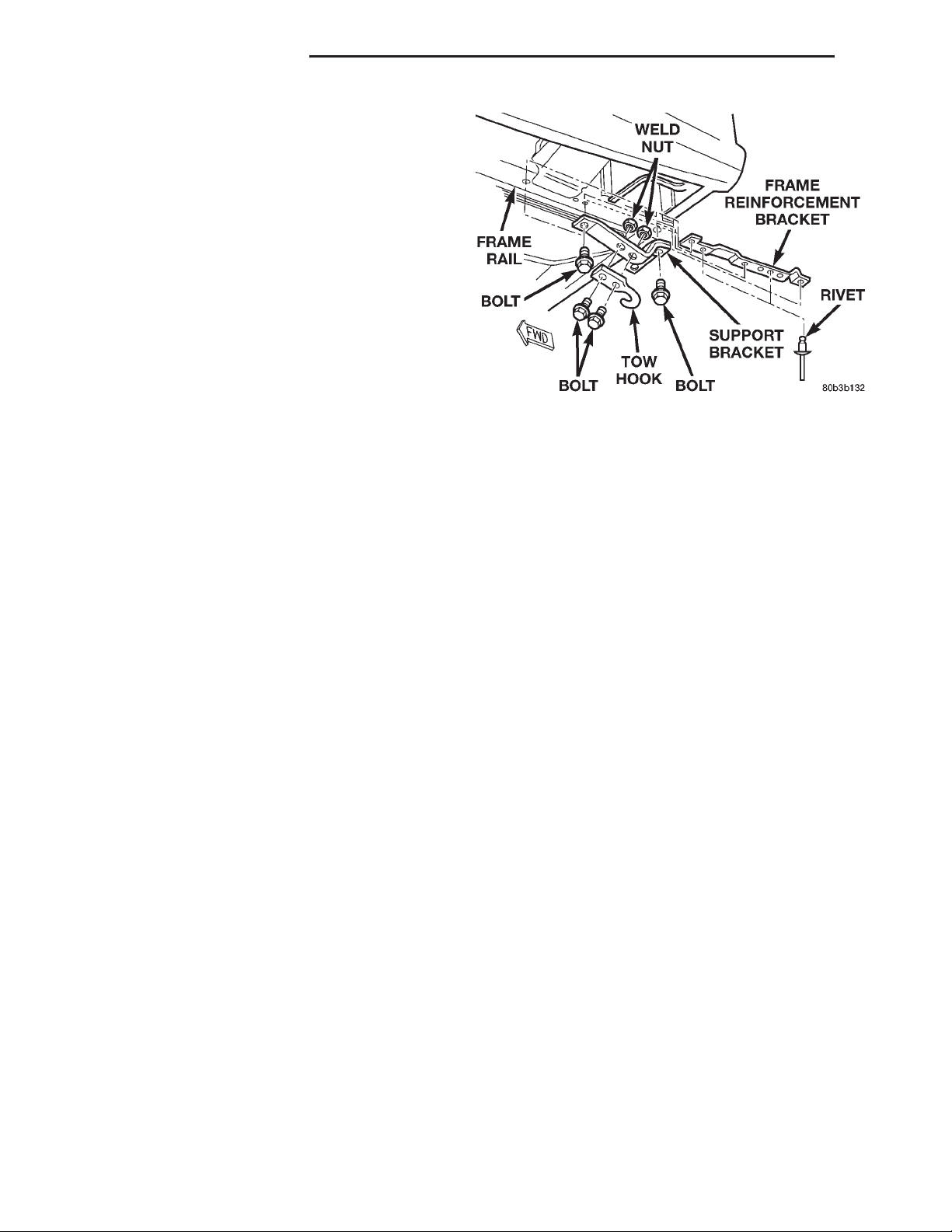
(1) Remove bolts that attach tow hook bracket and
tow hook to frame rail (Fig. 6).
(2) Remove bracket and tow hook from frame rail.
INSTALLATION
(1) Position bracket and tow hook on frame rail.
(2) Install bolts that attach tow hook bracket and
tow hook to frame rail. Tighten bolts to 94 N·m (70
ft. lbs.) torque.
Fig. 6 Rear Tow Hook
Page 5
XJ FRAME AND BUMPERS 13 - 5
FRAME
INDEX
page page
REMOVAL AND INSTALLATION
FRONT SKID PLATE ...................... 5
FUEL TANK SKID PLATE ................... 5
TRAILER HITCH .......................... 6
REMOVAL AND INSTALLATION
FRONT SKID PLATE
REMOVAL
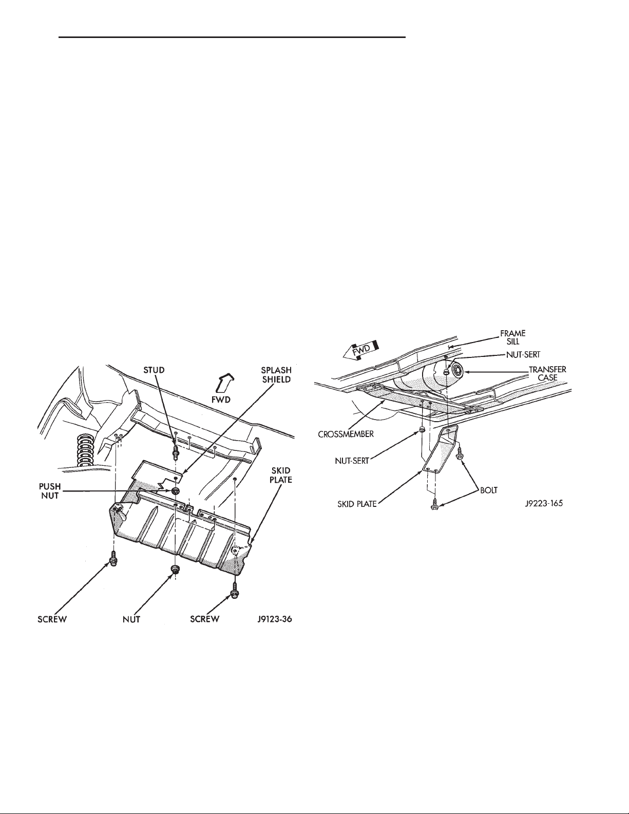
(1) Remove the screws that attach skid plate to
side sills.
(2) Remove the nuts that attach the skid plate to
the crossmember (Fig. 1).
(3) Remove the skid plate from the vehicle.
TRANSFER CASE SKID PLATE .............. 5
SPECIFICATIONS
FRAME DIMENSIONS ..................... 6
FRAME TORQUE SPECIFICATIONS .......... 8
TRANSFER CASE SKID PLATE
REMOVAL
(1) Support skid plate.
(2) Remove bolts that attach skid plate to trans-
mission support crossmember and frame sill (Fig. 2).
(3) Remove support and skid plate from vehicle.
Fig. 1 Front Skid Plate
INSTALLATION
(1) Position the skid plate at front crossmember
and side sills.
(2) Install the nuts to attach the skid plate to
crossmember.
(3) Install the screws to attach skid plate to side
sills.
Fig. 2 Transfer Case Skid Plate
INSTALLATION
(1) Position and support skid plate at frame sill
and transmission support crossmember.
(2) Attach skid plate to frame sill and crossmember with bolts. Tighten bolts to 22 N·m (16 ft. lbs.)
torque.
FUEL TANK SKID PLATE
REMOVAL
(1) Position a support under skid plate.
(2) Remove bolts that attach skid plate to underbody side rails (Fig. 3).
(3) Remove support and skid plate from vehicle.
INSTALLATION
(1) Position and support skid plate under fuel
tank.
Page 6
13 - 6 FRAME AND BUMPERS XJ
REMOVAL AND INSTALLATION (Continued)
INSTALLATION
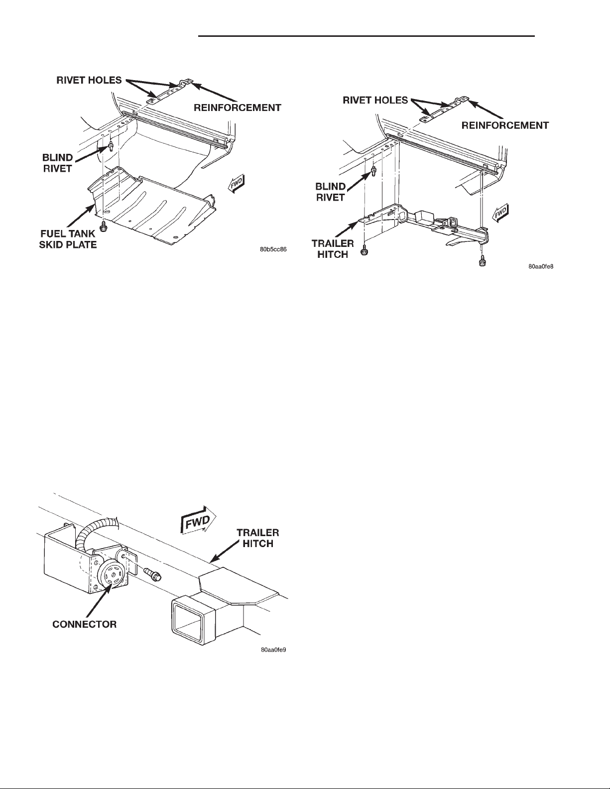
Fig. 3 Fuel Tank Skid Plate
(2) Install bolts to attach skid plate to underbody
rails. Tighten bolts to 74 N·m (55 ft. lbs.) torque.
(3) Remove support from under skid plate.
TRAILER HITCH
REMOVAL
(1) If necessary, remove the trailer tow wire har-
ness connector from the hitch (Fig. 4).
(2) Support the hitch.
(3) Remove the bolts that attach the trailer hitch
to the frame sills and reinforcement brackets (Fig. 5).
(4) If equipped, remove the fuel tank skid plate.
NOTE: The reinforcement brackets are held on the
frame sills with two blind rivets.
(1) Install frame reinforcement brackets, if
removed. Slide the brackets through the vehicle rear
sill openings and attach to the frame sills with blind
rivets.
(2) Using an adequate lifting device, position hitch
at the proper location for installation on vehicle and
support it.
(3) If equipped, position fuel tank skid plate on
vehicle frame sills.
(4) Loosely install the bolts to attach the trailer
hitch (and the skid plate) to frame sills and reinforcement brackets.
(5) Tighten all bolts/nuts to 74 N·m (55 ft. lbs.)
torque.
(6) Remove the lift/support.
(7) If removed, attach the trailer wire harness connector to the hitch.
Fig. 5 Trailer Hitch
Fig. 4 Trailer Hitch Harness Connector
SPECIFICATIONS
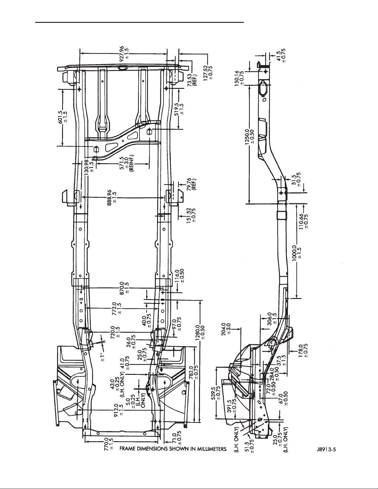
FRAME DIMENSIONS
Frame dimensions are listed in millimeter scale.
All dimensions are from center to center of Principal
Locating Point (PLP), or from center to center of PLP
and fastener location (Fig. 6).
Page 7
XJ FRAME AND BUMPERS 13 - 7
SPECIFICATIONS (Continued)
Fig. 6 Frame Dimensions
Page 8

13 - 8 FRAME AND BUMPERS XJ
SPECIFICATIONS (Continued)
FRAME TORQUE SPECIFICATIONS
DESCRIPTION TORQUE
Front Skid Plate Screw ................42N·m
(31 ft. lbs.)
Front Skid Plate Nut ..................17N·m
(125 in. lbs.)
Transfer Case Skid Plate Bolt ...........22N·m
(16 ft. lbs.)
Fuel Tank Skid Plate Bolt ..............74N·m
(55 ft. lbs.)
Front Bumper End Cap to
Mounting Bracket Nut ................9N·m
(7 ft. lbs.)
Front Bumper Mounting
Bracket to Frame Bolt ...............55N·m
(41 ft. lbs.)
Front Bumper to
Mounting Bracket Bolt ...............55N·m
(41 ft. lbs.)
Front Tow Hook Bolt .................100N·m
(74 ft. lbs.)
Front Tow Hook
Reinforcement Bolt ..................30N·m
(22 ft. lbs.)
Rear Bumper to
Mtg. Bracket Nut .................. 55N·m
(41 ft. lbs.)
Rear Bumper Mtg. Bracket to
Rear Sill Bolt ......................55N·m
(41 ft. lbs.)
Rear Tow Hook Bolt ...................94N·m
(70 ft. lbs.)
Trailer Tow
Reinforcement Brkt Bolt .............74N·m
(55 ft. lbs.)
 Loading...