

Page 1
XJ EXHAUST SYSTEM AND TURBOCHARGER 11 - 1
EXHAUST SYSTEM AND TURBOCHARGER
CONTENTS
page page
GENERAL INFORMATION
EXHAUST HEAT SHIELDS ................. 1
EXHAUST SYSTEM ....................... 1
REMOVAL AND INSTALLATION
EXHAUST MANIFOLD AND TURBOCHARGER
(LHD) ................................ 3
EXHAUST MANIFOLD AND TURBOCHARGER
(RHD) ................................ 5
GENERAL INFORMATION
EXHAUST SYSTEM
The basic exhaust system consists of an engine
exhaust manifold, exhaust pipe, exhaust heat
shield(s), muffler and exhaust tailpipe.
The exhaust system uses a single muffler.
The exhaust system must be properly aligned to
prevent stress, leakage and body contact. If the system contacts any body panel, it may amplify objectionable noises originating from the engine or body.
When inspecting an exhaust system, critically
inspect for cracked or loose joints, stripped screw or
bolt threads, corrosion damage and worn, cracked or
broken hangers. Replace all components that are
badly corroded or damaged. DO NOT attempt to
repair.
When replacement is required, use original equipment parts (or equivalent). This will assure proper
alignment and provide acceptable exhaust noise levels.
EXHAUST PIPE .......................... 2
INTAKE MANIFOLD ...................... 10
MUFFLER AND EXHAUST TAILPIPE .......... 2
SPECIFICATIONS
TORQUE SPECIFICATIONS ................ 10
EXHAUST HEAT SHIELDS
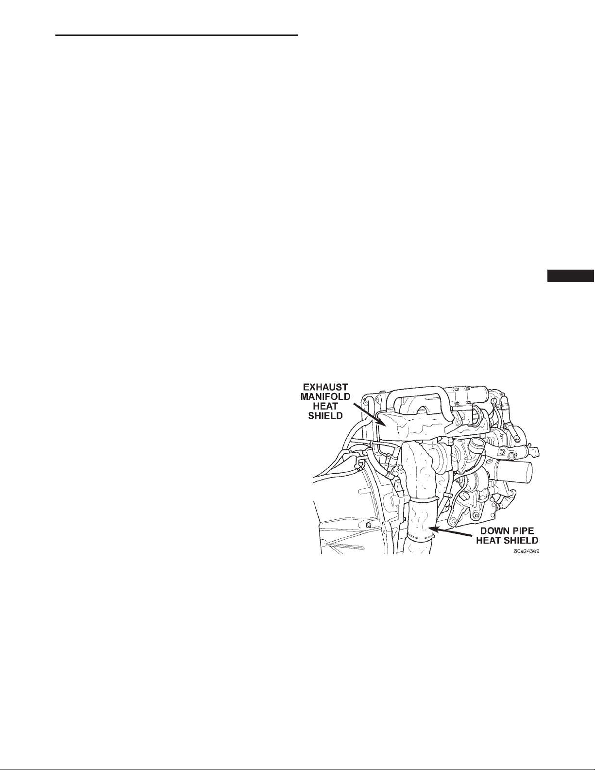
Exhaust heat shields are needed to protect both
the vehicle and the environment from the high temperatures (Fig. 1).
DO NOT allow the engine to operate at fast idle for
extended periods (over 5 minutes). This condition
may result in excessive temperatures in the exhaust
system and on the floor pan.
CAUTION: Avoid application of rust prevention
compounds or undercoating materials to exhaust
system floor pan exhaust heat shields. Light overspray near the edges is permitted. Application of
coating will result in excessive floor pan temperatures and objectionable fumes.
Fig. 1 Heat Shields
Page 2
11 - 2 EXHAUST SYSTEM AND TURBOCHARGER XJ
REMOVAL AND INSTALLATION
EXHAUST PIPE
WARNING: IF TORCHES ARE USED WHEN WORKING ON THE EXHAUST SYSTEM, DO NOT ALLOW
THE FLAME NEAR THE FUEL LINES.
REMOVAL
(1) Raise and support the vehicle.
(2) Saturate the bolts and nuts at turbo down pipe
to exhaust pipe with heat valve lubricant. Allow 5
minutes for penetration.
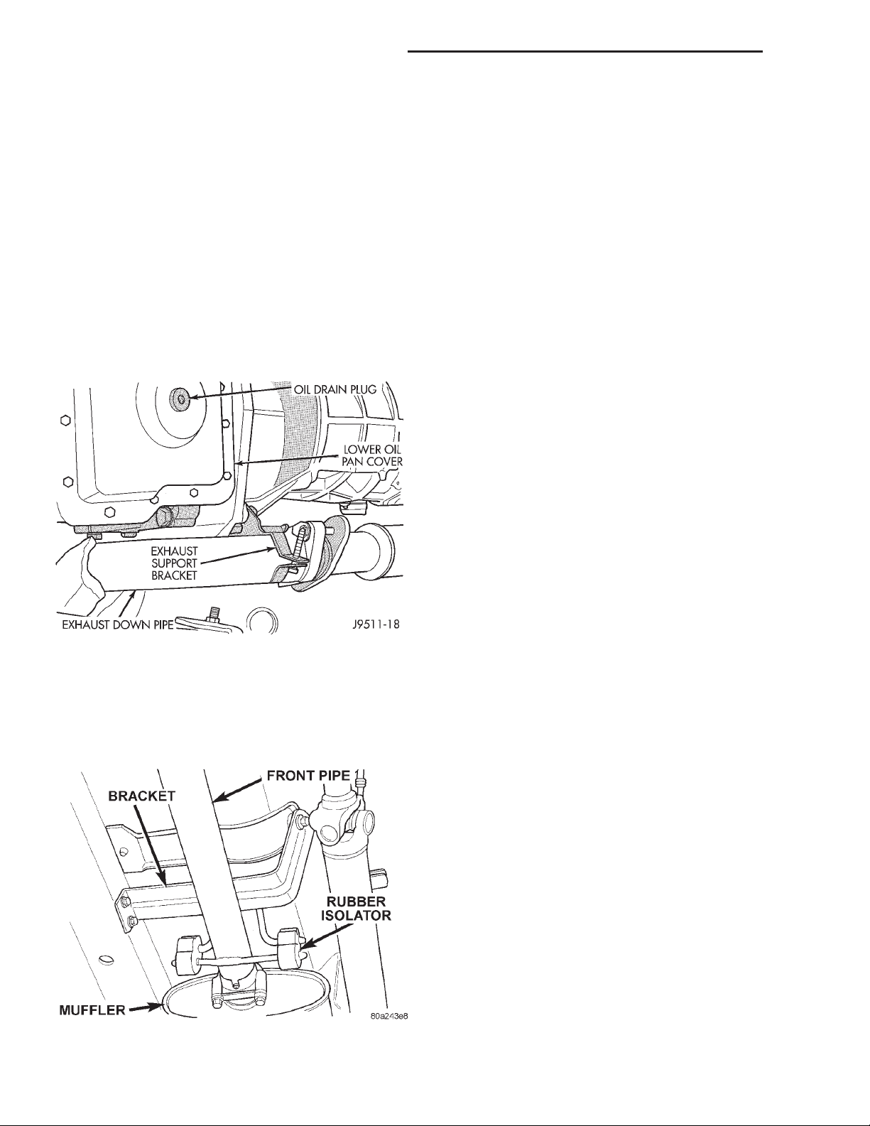
(3) Disconnect bolts from exhaust pipe to turbo
down pipe (Fig. 2).
Fig. 2 Exhaust Down Pipe to Front Exhaust Pipe
(4) Remove the clamp nuts at muffler (Fig. 3). To
remove the exhaust pipe from the muffler, apply heat
until the metal becomes cherry red. Disconnect the
exhaust pipe from the muffler. Remove the exhaust
pipe.
INSTALLATION
(1) Assemble exhaust pipe to muffler, loosely to
permit proper alignment of all parts.
(2) Connect the exhaust pipe to the turbo down
pipe manifold. Tighten the bolts to 22.5 N·m torque.
(3) Use a new clamp and tighten the nuts to 43
N·m torque.
(4) Lower the vehicle.
(5) Start the engine and inspect for exhaust leaks
and exhaust system contact with the body panels.
Adjust the alignment, if needed.
MUFFLER AND EXHAUST TAILPIPE
All original equipment exhaust systems are manufactured with the exhaust tailpipe welded to the muffler. Service replacement mufflers and exhaust
tailpipes are either clamped together or welded
together.
WARNING: IF TORCHES ARE USED WHEN WORKING ON THE EXHAUST SYSTEM, DO NOT ALLOW
THE FLAME NEAR THE FUEL LINES.
REMOVAL
(1) Raise and support the vehicle.
(2) Remove the front muffler clamp from the
exhaust pipe and muffler connection.
(3) Remove the rear exhaust tailpipe hanger clamp
and remove the exhaust tailpipe from the front
exhaust tailpipe hanger.
(4) Remove the exhaust tailpipe assembly from the
muffler.
INSTALLATION
(1) Install the muffler onto the exhaust pipe.
Install the clamp and tighten the nuts finger tight.
(2) Install the exhaust tailpipe into the rear of the
muffler.
(3) Install the exhaust tailpipe/muffler assembly
on the rear exhaust tailpipe hanger. Make sure that
the exhaust tailpipe has sufficient clearance from the
floor pan.
(4) Install the remaining clamps and the front
exhaust tailpipe hanger.
(5) Tighten the nuts on the muffler-to-exhaust pipe
clamp to 43 N·m torque.
(6) Tighten the nuts on the muffler-to-exhaust pipe
clamp to 43 N·m torque.
(7) Lower the vehicle.
(8) Start the engine and inspect for exhaust leaks
and exhaust system contact with the body panels.
Adjust the alignment, if needed.
Fig. 3 Front Pipe to Muffler
Page 3
XJ EXHAUST SYSTEM AND TURBOCHARGER 11 - 3
REMOVAL AND INSTALLATION (Continued)
EXHAUST MANIFOLD AND TURBOCHARGER (LHD)
REMOVAL
(1) Disconnect the negative battery cable.
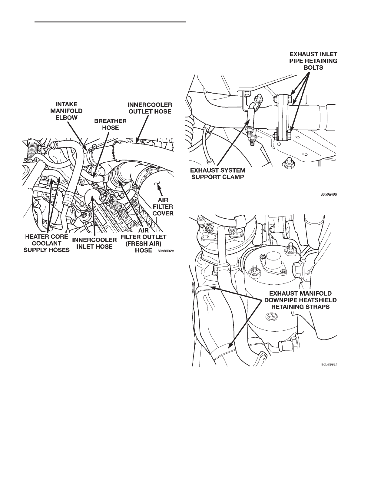
(2) Disconnect the breather hose from air cleaner
outlet hose (Fig. 4).
Fig. 4 Engine Compartment
(3) Remove the air filter cover and hose from tur-
bocharger, remove the assembly (Fig. 4).
(4) Remove the EGR vacuum supply hose from the
EGR valve.
(5) Remove the innercooler inlet and outlet hoses
from the engine (Fig. 4).
(6) Remove the (2) bolts holding the EGR tube to
the EGR valve.
(7) Remove the intake manifold elbow and EGR
valve as an assembly.
(8) Raise the vehicle on a hoist.
(9) Drain the cooling system. Refer to Group 7,
Cooling System for procedure.
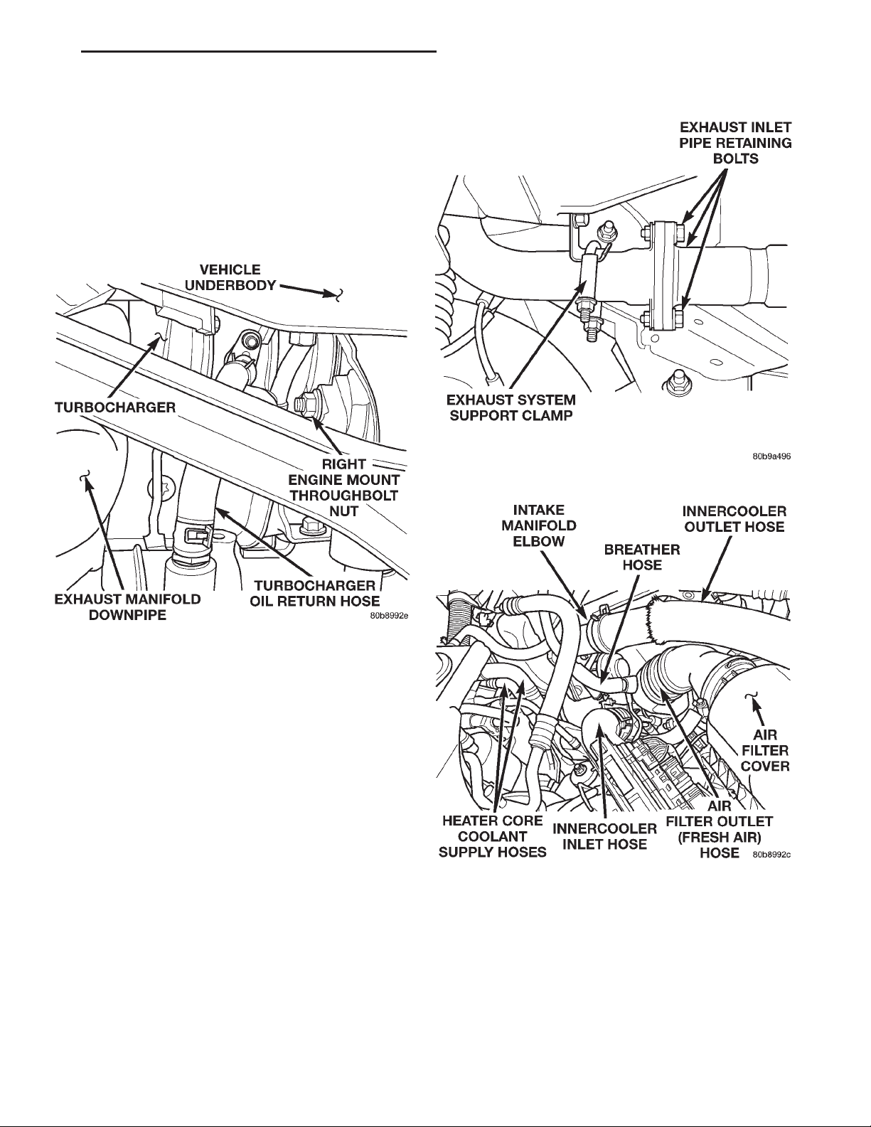
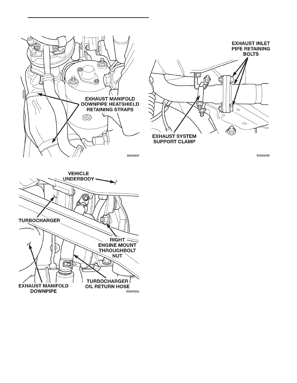
(10) Remove the exhaust system support clamp
(Fig. 5).
(11) Disconnect the exhaust system at the (3) bolt
flange (Fig. 5).
CAUTION: Heatshield is very sharp. Wear gloves to
prevent injury.
(12) Unstrap the exhaust downpipe heatshield
(Fig. 6).
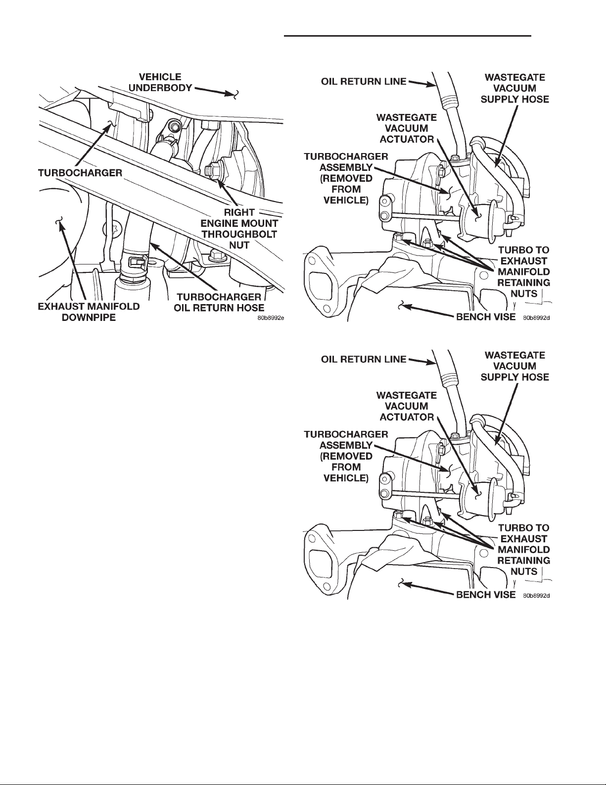
(13) Disconnect the turbocharger oil return hose
from the engine block (Fig. 7).
Fig. 5 Exhaust System Inlet Pipe Connection
Fig. 6 Exhaust Downpipe Heatshield
(14) Lower the vehicle from the hoist.
(15) Remove the EGR tube from exhaust manifold.
(16) Remove the (2) exhaust manifold heatshield
retaining bolts and remove the heatshield.
(17) Remove the heater core supply hoses from the
vehicle.
(18) Remove the oil pressure supply line bango
bolt from the turbocharger.
Page 4
11 - 4 EXHAUST SYSTEM AND TURBOCHARGER XJ
REMOVAL AND INSTALLATION (Continued)
Fig. 7 Turbocharger Oil Return Hose
CAUTION: Heatshield is very sharp. Wear gloves to
prevent injury.
(19) Remove the exhaust downpipe heatshield by
pulling straight up.
(20) Remove the (5) bolts from exhaust manifold
downpipe and remove pipe.
(21) Remove the (8) exhaust manifold retaining
bolts, it is necessary to access the bolt behind the
manifold outlet from the underneath of the vehicle.
(22) Remove the exhaust manifold and turbocharger assembly from the vehicle.
(23) Place assembly in a vice to remove the (3)
exhaust manifold to turbocharger retaining nuts (Fig.
8).
Cleaning
All old gaskets should be inspected for any tears or
signs of prior leakage. If any gaskets show such indications, they should be replaced with new gaskets.
All gasket mating surfaces must be cleaned of old
gasket material to produce a smooth and dirt free
sealing surface for the new gasket.
INSTALLATION
(1) Transfer the oil return hose to the new turbocharger (Fig. 9).
(2) Install the turbo on the exhaust manifold (Fig.
9). Torque the nuts to 32 N·m (23 ft. lbs.).
(3) Install the exhaust manifold and turbocharger
assembly in the vehicle.
(4) Install the (8) exhaust manifold retaining nuts.
Torque nuts to 32 N·m (23 ft. lbs.).
Fig. 8 Turbocharger / Exhaust Manifold Assembly
Fig. 9 Turbocharger / Exhaust Manifold Assembly
(5) Install the exhaust manifold downpipe. Torque
bolts to 32 N·m (23 ft. lbs.).
CAUTION: Heatshield is very sharp. Wear gloves to
prevent injury.
(6) Slide the exhaust downpipe heatshield down
over pipe. Do not attempt to strap heatshield in position at this time, wait until vehicle is raised on hoist.
Page 5
XJ EXHAUST SYSTEM AND TURBOCHARGER 11 - 5
REMOVAL AND INSTALLATION (Continued)
(7) Install the oil pressure supply line on turbocharger. Torque bango bolt fitting to 27 N·m (20 ft.
lbs.).
(8) Install the heater core supply hoses.
(9) Position and install the exhaust manifold heatshield. Torque bolts to 11 N·m (97 in. lbs.).
(10) Raise the vehicle on a hoist.
(11) Install the turbocharger oil return hose on the
engine block (Fig. 10).
Fig. 10 Turbocharger Oil Return Hose
(12) Strap the exhaust downpipe heatshield in its
original position.
(13) Connect the exhaust system at the (3) bolt
flange (Fig. 11). Torque the bolts to 23 N·m (17 ft.
lbs.).
(14) Install the exhaust system support clamp
(Fig. 11). Torque nuts to 23 N·m (17 ft. lbs.).
(15) Lower the vehicle from the hoist.
(16) Install the intake manifold elbow and EGR
valve as an assembly. Torque bolts to 27 N·m (20 ft.
lbs.).
(17) Install the (2) bolts holding the EGR tube to
the EGR valve. Torque bolts to 27 N·m (20 ft. lbs.).
(18) Install the innercooler inlet and outlet hoses
on the engine (Fig. 12).
(19) Install the EGR vacuum supply hose on the
EGR valve.
(20) Install the air filter cover and outlet hose on
turbocharger (Fig. 12).
(21) Connect the breather hose on the air cleaner
outlet hose (Fig. 12).
(22) Fill the cooling system. Refer to Group 7,
Cooling System for procedure.
(23) Connect the negative battery cable
Fig. 11 Exhaust System Inlet Pipe Connection
Fig. 12 Engine Compartment
(24) Start the engine and check for leaks.
EXHAUST MANIFOLD AND TURBOCHARGER (RHD)
REMOVAL
(1) Disconnect the negative battery cable.
(2) Disconnect the breather hose from the air
cleaner outlet hose.
Page 6
11 - 6 EXHAUST SYSTEM AND TURBOCHARGER XJ
REMOVAL AND INSTALLATION (Continued)
(3) Remove the air filter cover and the hose from
the turbocharger, remove the assembly.
(4) Raise the vehicle on a hoist.
(5) Drain the cooling system. Refer to Group 7,
Cooling System for the procedure.
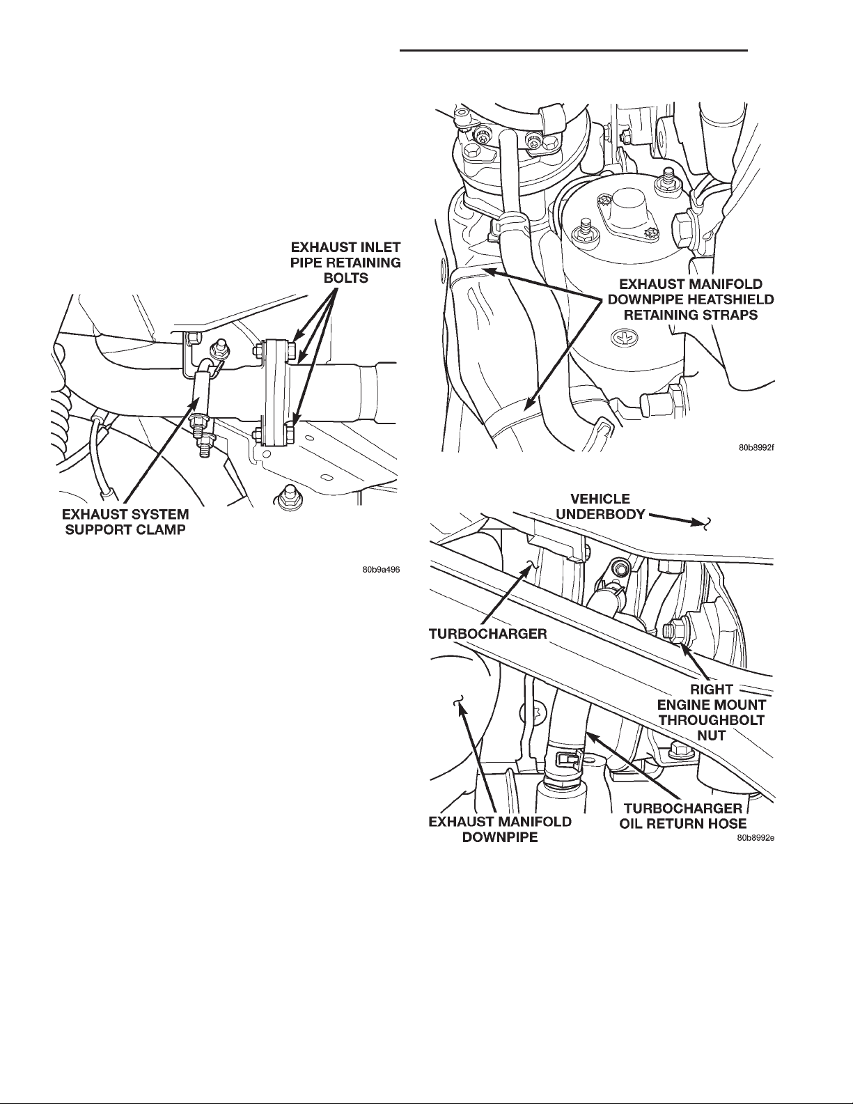
(6) Remove the exhaust system support clamp
(Fig. 13).
Fig. 13 Exhaust System Inlet Pipe Connection
(7) Disconnect the exhaust system at the (3) bolt
flange (Fig. 13).
CAUTION: Heatshield is very sharp. Wear gloves to
prevent injury.
(8) Unstrap the exhaust downpipe heatshield (Fig.
14).
CAUTION: Heatshield is very sharp. Wear gloves to
prevent injury.
(9) Remove the exhaust downpipe heatshield by
pulling straight down.
(10) Disconnect the turbocharger oil return hose
from the engine block (Fig. 15).
(11) Lower the vehicle from the hoist.
(12) Disconnect the heater core coolant supply and
the brake vacuum supply hoses from the right side of
the engine. Remove the steel line support bracket
from the top of the rocker cover and position the
assembly out of the way.
(13) Remove the EGR vacuum supply hose from
the EGR valve.
(14) Remove the innercooler inlet and outlet hoses
from the engine.
Fig. 14 Exhaust Downpipe Heatshield
Fig. 15 Turbocharger Oil Return Hose
(15) Remove the (2) bolts holding the EGR tube to
the EGR valve.
(16) Remove the intake manifold elbow and the
EGR valve as an assembly.
(17) Remove the EGR tube from the exhaust man-
ifold.
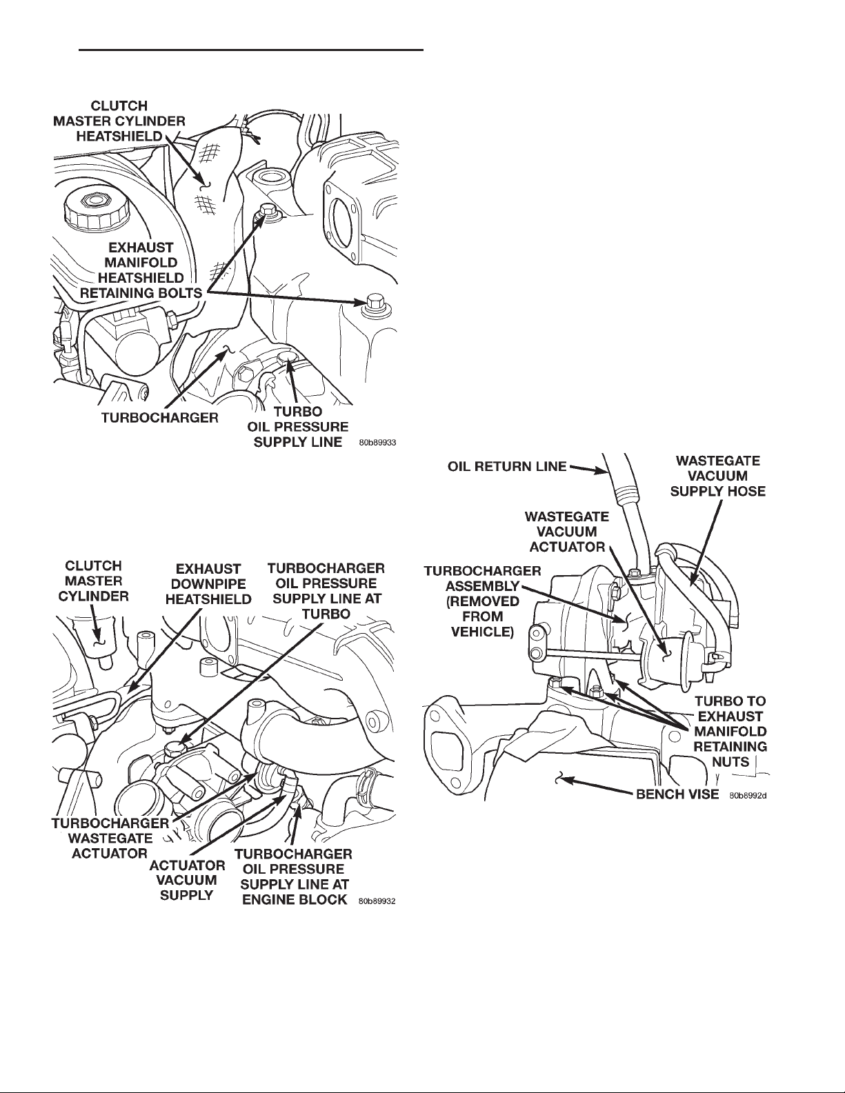
(18) Remove the (2) exhaust manifold heatshield
retaining bolts and remove the heatshield (Fig. 16).
(19) Remove the oil pressure supply line from the
turbocharger (Fig. 16).
Page 7
XJ EXHAUST SYSTEM AND TURBOCHARGER 11 - 7
REMOVAL AND INSTALLATION (Continued)
(24) Disconnect the neutral safety switch electrical
connector at the clutch pedal.
(25) Remove the (2) clutch master cylinder retain-
ing nuts from the bulkhead.
(26) Working from the inside of the engine compartment, remove the clutch master cylinder from
the bulkhead and position the cylinder and line
assembly out of the way.
(27) Remove the (5) bolts from the exhaust manifold downpipe and remove the pipe.
(28) Remove the (8) exhaust manifold retaining
bolts, it is necessary to access the bolt behind the
manifold outlet from the underneath of the vehicle.
(29) Remove the steering shaft pinchbolt and slide
the shaft straight off of the gearbox input shaft. Position aside.
(30) Remove the exhaust manifold and the turbocharger assembly from the vehicle.
(31) Place the turbo assembly in a vice to remove
the (3) exhaust manifold to turbocharger retaining
nuts (Fig. 18).
Fig. 16 2.5L Turbo Diesel — Heatshields
(20) Remove the clutch master cylinder heatshield
(Fig. 16).
(21) Remove the wastegate actuator vacuum sup-
ply hose from the actuator (Fig. 17).
Fig. 17 R.H.D. Turbo Position & Orientation
(22) Remove the turbocharger oil pressure supply
line from the engine block (Fig. 17).
(23) Working inside of the vehicle, remove the
Knee Blocker. Refer to Group 8E, Instrument Panel
Systems for the procedure.
Fig. 18 Turbocharger / Exhaust Manifold Assembly
Cleaning
All old gaskets should be inspected for any tears or
signs of prior leakage. If any gasket shows such indications, it must be replaced with a new gasket. All
gasket mating surfaces must be cleaned of all old
gasket material to produce a smooth and dirt free
sealing surface for the new gasket.
INSTALLATION
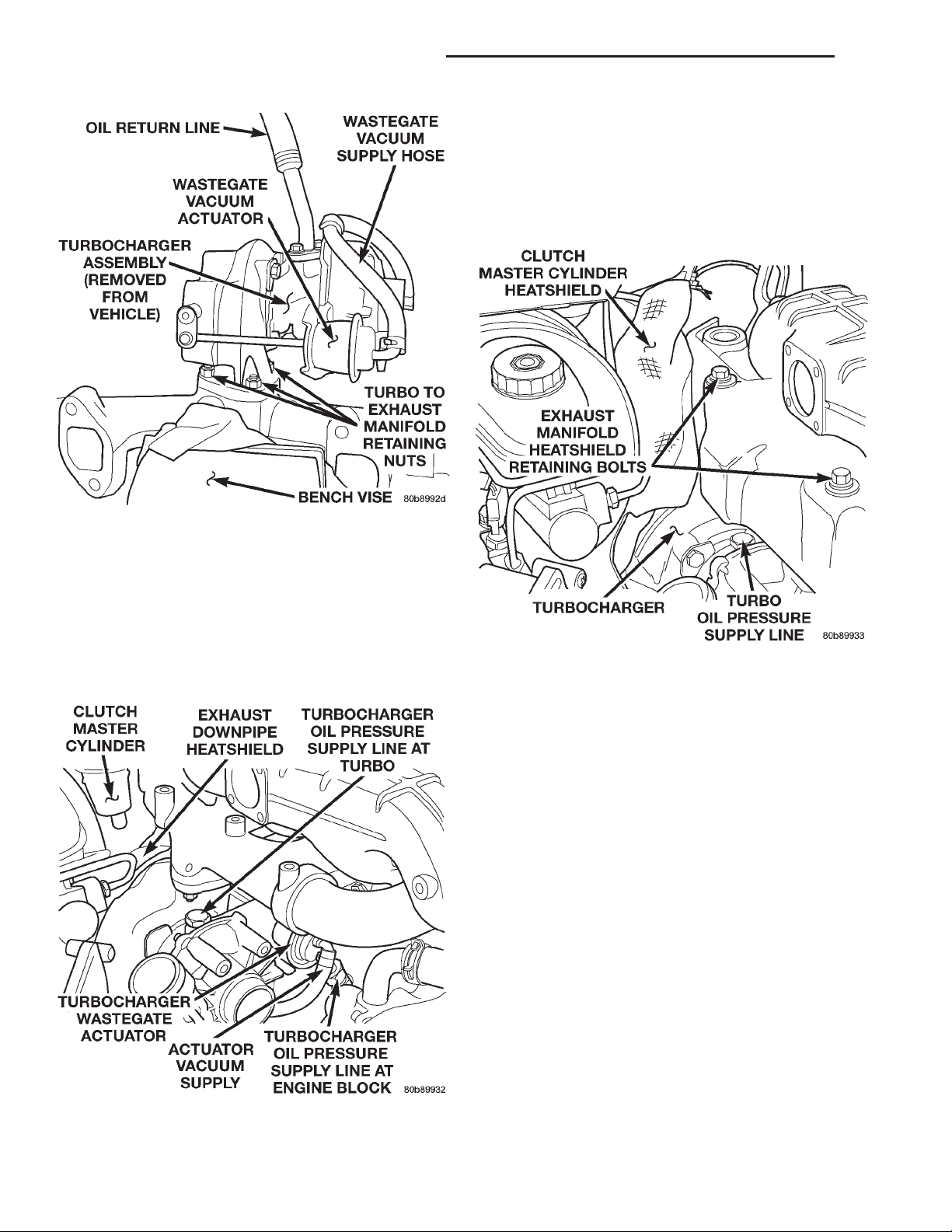
(1) Install the turbocharger on the exhaust manifold (Fig. 19). Torque nuts to 32 N·m (23 ft. lbs.).
Page 8
11 - 8 EXHAUST SYSTEM AND TURBOCHARGER XJ
REMOVAL AND INSTALLATION (Continued)
(5) Position the turbocharger oil pressure supply
line in its original position (Fig. 20). Torque the turbo
fitting to 27 N·m (20 ft. lbs.).
(6) Install the wastegate actuator vacuum supply
hose on the actuator (Fig. 20).
(7) Install the exhaust manifold heatshield (Fig.
21). Torque bolts to 11 N·m (97 in. lbs.).
Fig. 19 Turbocharger / Exhaust Manifold Assembly
(2) Install the exhaust manifold and turbocharger
assembly in the vehicle.
(3) Install the (8) exhaust manifold retaining nuts,
it is necessary to access the bolt behind the manifold
outlet from the underneath of the vehicle. Torque
nuts to 32 N·m (23 ft. lbs.).
(4) Install the exhaust manifold downpipe. Torque
the bolts to 32 N·m (23 ft. lbs.).
Fig. 20 R.H.D. Turbo Position & Orientation
Fig. 21 2.5L Turbo Diesel — Heatshields
(8) Install the EGR tube on the exhaust manifold.
Leave loose at this time.
(9) Raise the vehicle on a hoist.
CAUTION: Heatshield is very sharp. Wear gloves to
prevent injury.
(10) Slide the exhaust downpipe heatshield up
over the pipe and strap it in its original position (Fig.
22).
(11) Install the steering shaft. Torque the pinch
bolt to 49 N·m (36 ft. lbs.).
(12) Install the turbocharger oil return hose on the
engine block (Fig. 23).
(13) Connect the exhaust system at the (3) bolt
flange (Fig. 24). Torque the bolts to 23 N·m (17 ft.
lbs.).
(14) Install the exhaust system support clamp
(Fig. 24). Torque nuts to 23 N·m (17 ft. lbs.).
(15) Lower the vehicle on hoist.
(16) Install the clutch master cylinder through the
bulkhead.
(17) Working from the inside of the vehicle, Install
the (2) clutch master cylinder retaining nuts.
(18) Connect the neutral safety switch at the
clutch pedal.
Page 9
XJ EXHAUST SYSTEM AND TURBOCHARGER 11 - 9
REMOVAL AND INSTALLATION (Continued)
Fig. 22 Exhaust Downpipe Heatshield
Fig. 23 Turbocharger Oil Return Hose
(19) Install the Knee Blocker. Refer to Group 8E,
Instrument Panel Systems for procedure.
Fig. 24 Exhaust System Inlet Pipe Connection
(20) Install the clutch master cylinder heatshield.
(21) Install the intake manifold elbow and the
EGR valve as an assembly. Torque the intake elbow
bolts to 27 N·m (20 ft. lbs.).
(22) Install the (2) bolts holding the EGR tube to
the EGR valve. Torque to bolts 27 N·m (20 ft. lbs.).
(23) Torque the EGR tube on the exhaust manifold
to 28 N·m (21 ft. lbs.).
(24) Install the innercooler inlet and outlet hoses
on the engine.
(25) Install the EGR vacuum supply hose on the
EGR valve.
(26) Install the air filter cover and outlet hose on
the turbocharger.
(27) Connect the breather hose on the air cleaner
outlet hose.
(28) Install the heater core coolant supply and the
brake vacuum supply lines in there original position.
(29) Connect the negative battery cable.
(30) Fill the cooling system. Refer to Group 7,
Cooling System for the procedure.
(31) Start the engine and check for leaks.
Page 10

11 - 10 EXHAUST SYSTEM AND TURBOCHARGER XJ
REMOVAL AND INSTALLATION (Continued)
INTAKE MANIFOLD
REMOVAL
(1) Remove exhaust manifold and turbocharger
assembly.
(2) Remove water manifold.
(3) Remove intake manifold.
CLEANING
Clean the intake manifold and cylinder head mat-
ing surfaces. DO NOT allow foreign material to
enter either the intake manifold or the ports in
the cylinder head.
INSTALLATION
(1) Install the new intake manifold gasket.
(2) Position the intake manifold in place and fin-
ger tighten the mounting nuts.
(3) Tighten the fasteners in sequence and to the
specified torque 30 N·m.
(4) Position the water manifold in place and finger
tighten the mounting nuts.
(5) Tighten the fasteners to the specified torque 12
N·m.
(6) Install exhaust manifold and turbocharger
assembly.
(7) Install charge air cooler hose to intake mani-
fold.
(8) Connect the battery negative cable.
(9) Start engine and check for leaks.
SPECIFICATIONS
TORQUE SPECIFICATIONS
Description Torque
EGR
Attaching Nuts .......................28N·m
EGR
TubeNut ...........................34N·m
EGR
Tube Flange Bolts ....................26N·m
Exhaust Manifold
Nuts ...............................30N·m
Exhaust Manifold
Heat Shield Nuts .....................11N·m
Exhaust Pipe
Support Clamp Bolts .................22.5 N·m
Exhaust Pipe
Support Clamp Screw ................22.5 N·m
Intake Manifold
Nuts ...............................30N·m
Muffler-to-Exhaust Pipe
Clamp Nuts .........................43N·m
Tail Pipe Clamp
Hanger bolt ........................22.5 N·m
Turbocharger-to-Exhaust manifold
Nuts ...............................27N·m
Turbocharger
Oil Feed Line .......................27.4 N·m
Turbocharger Down Pipe-to-Exhaust Pipe
Bolts/Nuts .........................22.5 N·m
Turbocharger Down Pipe-to-Turbocharger
Bolts ...............................27N·m
 Loading...