

Page 1
XJ EXHAUST SYSTEM 11 - 1
EXHAUST SYSTEM
TABLE OF CONTENTS
page page
DESCRIPTION AND OPERATION
EXHAUST SYSTEM........................1
CATALYTIC CONVERTERS ..................2
MUFFLER ...............................3
TAILPIPE................................4
DIAGNOSIS AND TESTING
EXHAUST SYSTEM........................4
DESCRIPTION AND OPERATION
EXHAUST SYSTEM
DESCRIPTION
The basic exhaust system consists of exhaust manifold(s), exhaust pipe with oxygen sensors, catalytic
converter(s), heat shield(s), muffler and tailpipe
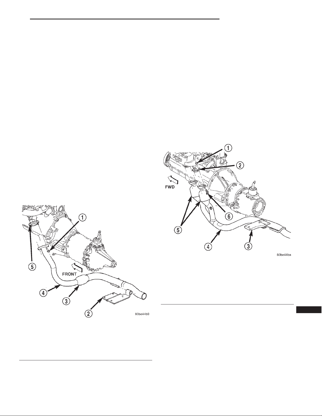
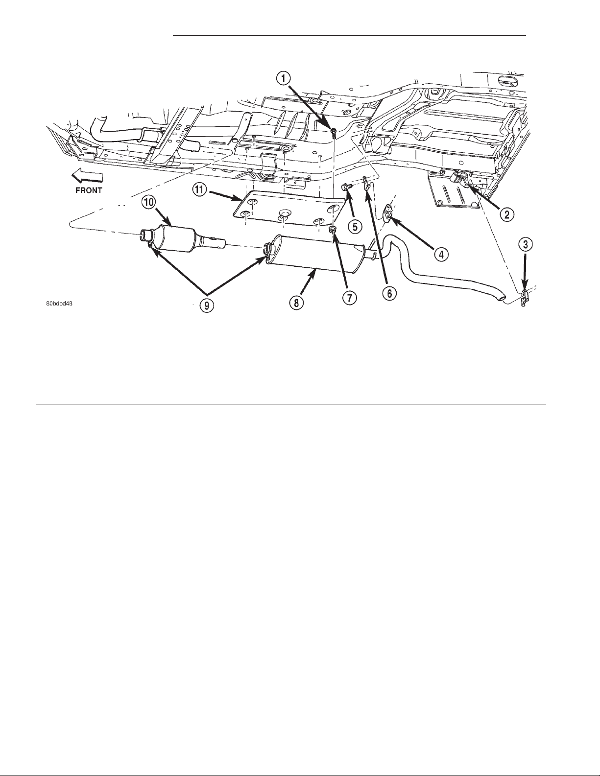
(Fig. 1) (Fig. 2) (Fig. 3)
REMOVAL AND INSTALLATION
EXHAUST PIPE...........................5
CATALYTIC CONVERTER....................6
MUFFLER AND TAILPIPE...................6
HEAT SHIELDS...........................8
SPECIFICATIONS
TORQUE SPECIFICATIONS..................8
Fig. 1 Exhaust Pipe—2.5L
1 – NUT
2 – TRANSMISSION SUPPORT
3 – MINI CATALYTIC CONVERTER
4 – EXHAUST PIPE
5 – EXHAUST MANIFOLD
Fig. 2 Exhaust Pipe—4.0L
1 – NUT
2 – EXHAUST MANIFOLD
3 – TRANSMISSION SUPPORT
4 – EXHAUST PIPE
5 – MINI CATALYTIC CONVERTER
6 – BOLT
Page 2
11 - 2 EXHAUST SYSTEM XJ
DESCRIPTION AND OPERATION (Continued)
Fig. 3 Exhaust System—Typical
1 – STUD
2 – TAIL PIPE HANGER
3 – CLAMP
4 – ISOLATOR
5 – BOLT
6 – TAIL PIPE HANGER
CATALYTIC CONVERTERS
DESCRIPTION
California emissions vehicles incorporate two mini
catalytic converters into the exhaust system. These
catalytic converters are made of stainless steel
designed to operate at extremely high temperatures.
The stainless steel catalytic converter body is
designed to last the life of the vehicle. Excessive heat
can result in bulging or other distortion, but exces-
7 – NUT
8 – MUFFLER
9 – CLAMP
10 – CATALYTIC CONVERTER
11 – HEAT SHIELD
sive heat will not be the fault of the converter. If
unburned fuel enters the converter, overheating may
occur. If a converter is heat-damaged, correct the
cause of the damage at the same time the converter
is replaced. Also, inspect all other components of the
exhaust system for heat damage.
Unleaded gasoline must be used to avoid con-
taminating the catalyst core.
Page 3
XJ EXHAUST SYSTEM 11 - 3
DESCRIPTION AND OPERATION (Continued)
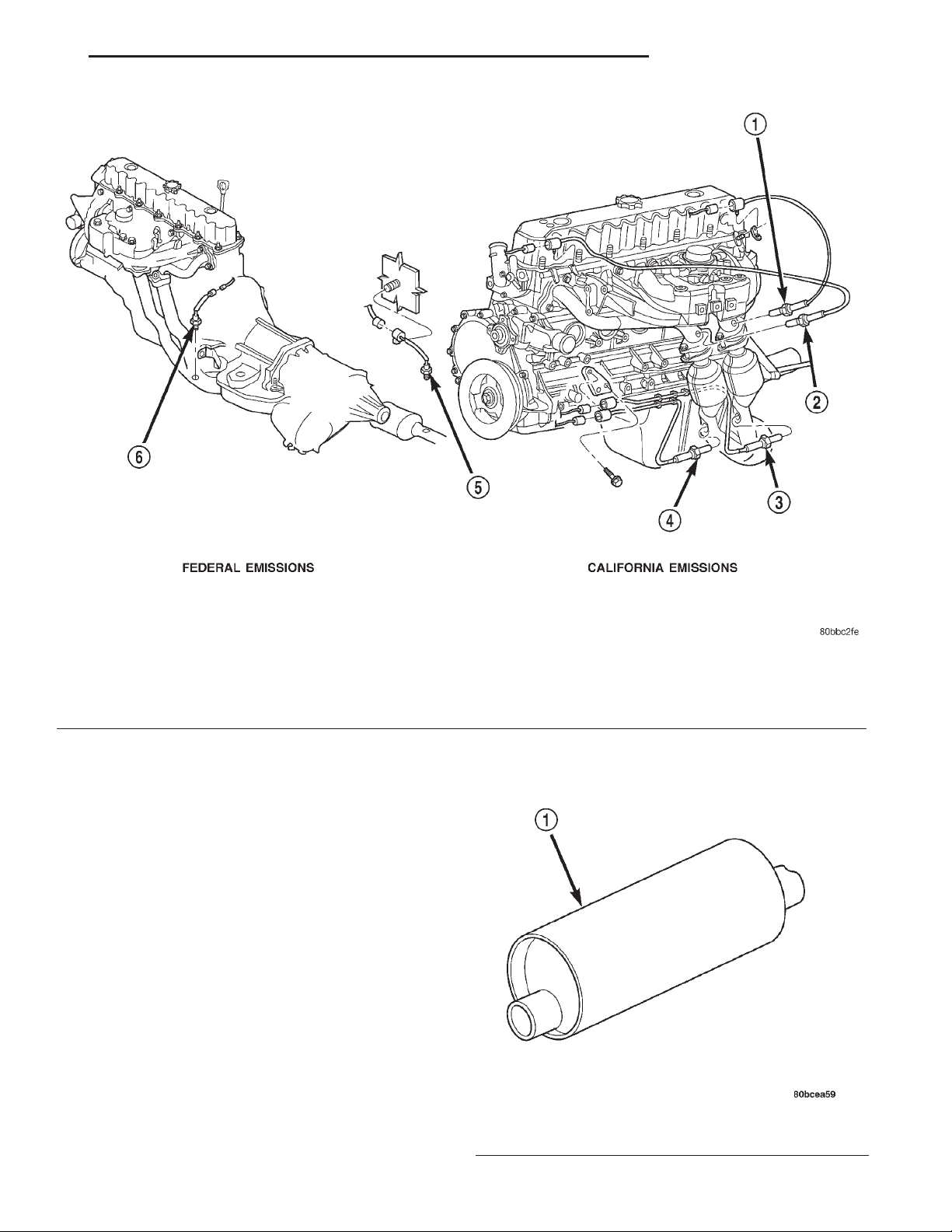
Fig. 4 4.0L Catalytic Converter and O2 Sensor Configuration—(California Emissions only)
1 – O2 SENSOR
2 – O2 SENSOR
3 – O2 SENSOR
Federal emission vehicles use only one catalytic
converter, However, California emission vehicles
incorporate two mini catalytic converters located
after the exhaust manifolds and before the inline catalytic converter (Fig. 4).
MUFFLER
DESCRIPTION
Both the 2.5L and 4.0L engines use a galvanized
steel muffler to control exhaust noise levels and
exhaust back pressure.
4 – O2 SENSOR
5 – O2 SENSOR
6 – O2 SENSOR
1 – MUFFLER
Fig. 5 Muffler—Typical
Page 4
11 - 4 EXHAUST SYSTEM XJ
DESCRIPTION AND OPERATION (Continued)
TAILPIPE
DESCRIPTION
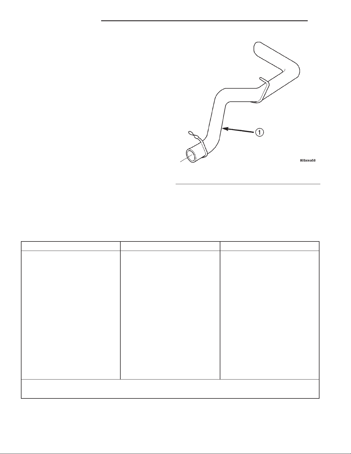
The tail pipe is also made of galvanized steel.
OPERATION
The tailpipe channels the exhaust out of the muffler and out from under the vehicle to control noise
and prevent exhaust gas fumes from entering the
passenger compartment.
Fig. 6 Tailpipe—Typical
1 – TAILPIPE
DIAGNOSIS AND TESTING
EXHAUST SYSTEM
EXHAUST SYSTEM DIAGNOSIS CHART
CONDITION POSSIBLE CAUSE CORRECTION
EXCESSIVE EXHAUST NOISE OR
LEAKING EXHAUST GASES
1. Leaks at pipe joints. 1. Tighten clamps/bolts at leaking
joints.
2. Rusted or blown out muffler. 2. Replace muffler. Inspect exhaust
system.
3. Broken or rusted out exhaust
pipe.
4. Exhaust pipe leaking at manifold
flange.
5. Exhaust manifold cracked or
broken.
6. Leak between exhaust manifold
and cylinder head.
7. Catalytic converter rusted or
blown out.
8. Restriction in exhaust system. 8. Remove restriction, if possible.
3. Replace exhaust pipe.
4. Tighten/replace flange attaching
nuts/bolts.
5. Replace exhaust manifold.
6. Tighten exhaust manifold to
cylinder head bolts.
7. Replace catalytic converter assy.
Replace restricted part if necessary.
When servicing and replacing exhaust system components, disconnect the oxygen sensor connector(s). Allowing
the exhaust to hang by the oxygen sensor wires will damage the harness and/or sensor.
Page 5
XJ EXHAUST SYSTEM 11 - 5
REMOVAL AND INSTALLATION
EXHAUST PIPE
WARNING: IF TORCHES ARE USED WHEN WORKING ON THE EXHAUST SYSTEM, DO NOT ALLOW
THE FLAME NEAR THE FUEL LINES.
CAUTION: When servicing exhaust system components, disconnect the oxygen sensor connector.
Allowing the exhaust system to hang by the oxygen
sensor harness will damage the wiring and/or sensor.
REMOVAL
(1) Raise and support the vehicle.
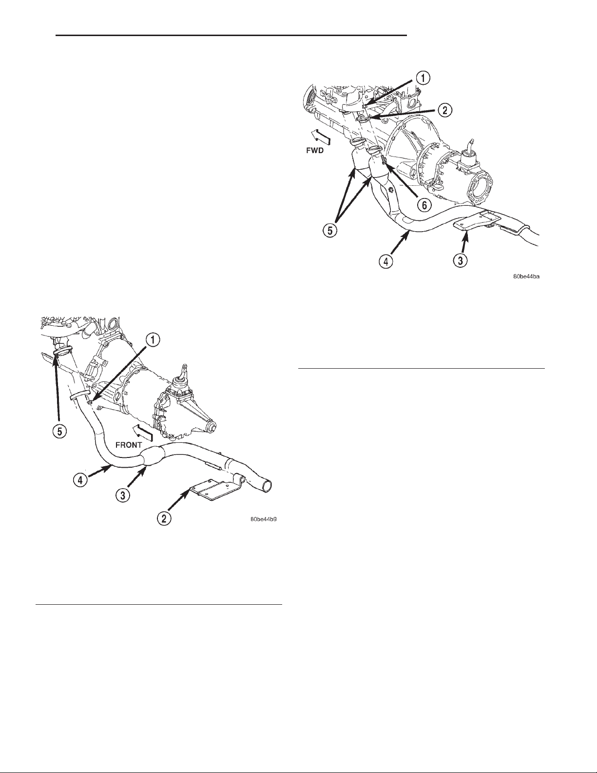
(2) Saturate the bolts and nuts with Mopart Rust
Penetrant (Fig. 7) (Fig. 8). Allow 5 minutes for penetration.
1 – NUT
2 – EXHAUST MANIFOLD
3 – TRANSMISSION SUPPORT
4 – EXHAUST PIPE
5 – MINI CATALYTIC CONVERTER
6 – BOLT
Fig. 8 Exhaust Pipe Removal—4.0L
Fig. 7 Exhaust Pipe Removal—2.5L
1 – NUT
2 – TRANSMISSION SUPPORT
3 – MINI CATALYTIC CONVERTER
4 – EXHAUST PIPE
5 – EXHAUST MANIFOLD
(3) Disconnect the oxygen sensor connector(s).
(4) Disconnect the exhaust pipe from the engine
exhaust manifold. Discard the seal (4.0L engine,
only).
(5) Support the transmission and remove the rear
crossmember.
(6) Remove the clamp nuts and clamp. To remove
the exhaust pipe from the catalytic converter, apply
heat until the metal becomes cherry red. Disconnect
the exhaust pipe from the catalytic converter.
Remove the exhaust pipe.
INSTALLATION
(1) Assemble exhaust pipe to manifold and catalytic converter loosely to permit proper alignment of
all parts.
(2) Use a new clamp and tighten the nuts to 61
N·m (45 ft. lbs.) torque.
(3) Connect the exhaust pipe to the engine exhaust
manifold (Fig. 7) (Fig. 8). Install a new seal between
the exhaust manifold and the exhaust pipe (4.0L
engine only). Tighten the nuts to 31 N·m (23 ft. lbs.)
torque.
(4) Install the rear crossmember. Install and
tighten the four (4) crossmember to rear mount nuts
to 22 N·m (16 ft. lbs.) Install and tighten the crossmember to sill bolts to 42 N·m (31 ft. lbs.) torque.
Remove the support from the transmission.
(5) Carefully coat the threads on the oxygen sensor(s) with anti-seize compound. Install the sensor
and tighten the nut to 27 N·m (20 ft. lbs.) torque.
(6) Lower the vehicle.
(7) Start the engine and inspect for exhaust leaks
and exhaust system contact with the body panels.
Adjust the alignment, if needed.
Page 6
11 - 6 EXHAUST SYSTEM XJ
REMOVAL AND INSTALLATION (Continued)
CATALYTIC CONVERTER
WARNING: IF TORCHES ARE USED WHEN WORKING ON THE EXHAUST SYSTEM, DO NOT ALLOW
THE FLAME NEAR THE FUEL LINES.
CAUTION: When servicing exhaust system components, disconnect the oxygen sensor connector.
Allowing the exhaust system to hang by the oxygen
sensor harness will damage the wiring and/or sensor.
REMOVAL
(1) Raise and support the vehicle.
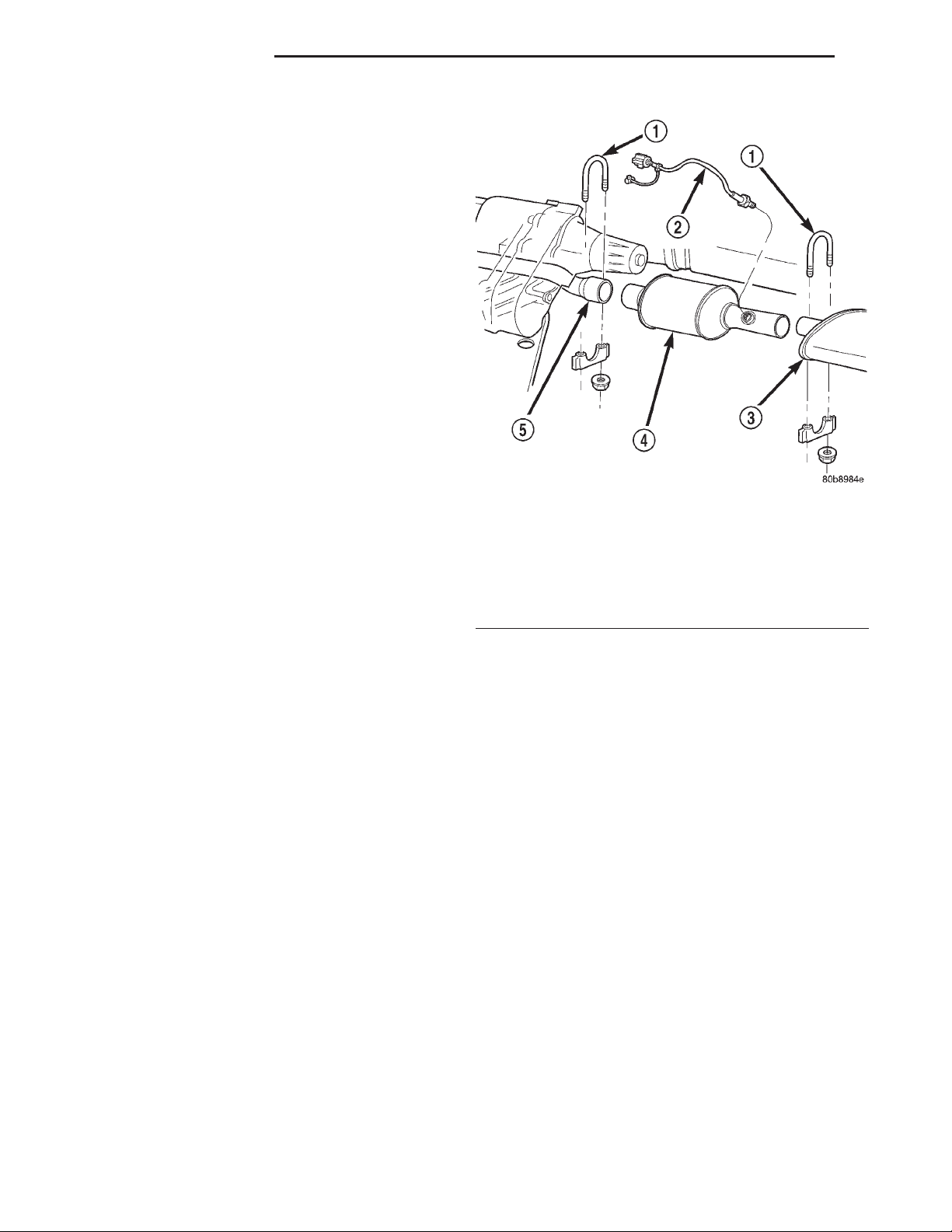
(2) Remove the clamps from the catalytic converter
and muffler connection (Fig. 9).
(3) Disconnect and remove the oxygen sensor from
the catalytic converter.
(4) Heat the catalytic converter and muffler connection with an oxyacetylene torch until the metal
becomes cherry red.
(5) While the metal is still cherry red, twist the
muffler assembly back and forth to separate it from
the catalytic converter.
(6) Disconnect the exhaust pipe from the catalytic
converter (Fig. 9). If needed, heat up the pipes to separate.
INSTALLATION
(1) Connect the catalytic converter to the exhaust
pipe and the muffler/tailpipe assy. (Fig. 9). Use a new
clamp and tighten the nuts to 61 N·m (45 ft. lbs.)
torque.
(2) Install the muffler onto the catalytic converter
until the alignment tab is inserted into the alignment slot.
(3) Install a new clamp at the muffler and catalytic converter connection (Fig. 9). Tighten the clamp
nut to 61 N·m (45 ft. lbs.) torque.
(4) Coat the oxygen sensor with anti-seize compound. Install the sensor and tighten the nut to 27
N·m (20 ft. lbs.) torque.
(5) Lower the vehicle.
(6) Start the engine and inspect for exhaust leaks
and exhaust system contact with the body panels.
Adjust the alignment, if needed.
MUFFLER AND TAILPIPE
All original equipment exhaust systems are manufactured with the exhaust tailpipe welded to the muffler. Service replacement mufflers and exhaust
tailpipes are either clamped together or welded
together.
Fig. 9 Catalytic Converter to Muffler and Exhaust
Pipe Connection
1 – EXHAUST CLAMP ASSEMBLY
2 – OXYGEN SENSOR
3 – MUFFLER
4 – CATALYTIC CONVERTER
5 – EXHAUST PIPE
WARNING: IF TORCHES ARE USED WHEN WORKING ON THE EXHAUST SYSTEM, DO NOT ALLOW
THE FLAME NEAR THE FUEL LINE.
CAUTION: When servicing exhaust system components, disconnect the oxygen sensor connector.
Allowing the exhaust system to hang by the oxygen
sensor harness will damage the wiring and/or sensor.
REMOVAL
(1) Raise and support the vehicle.
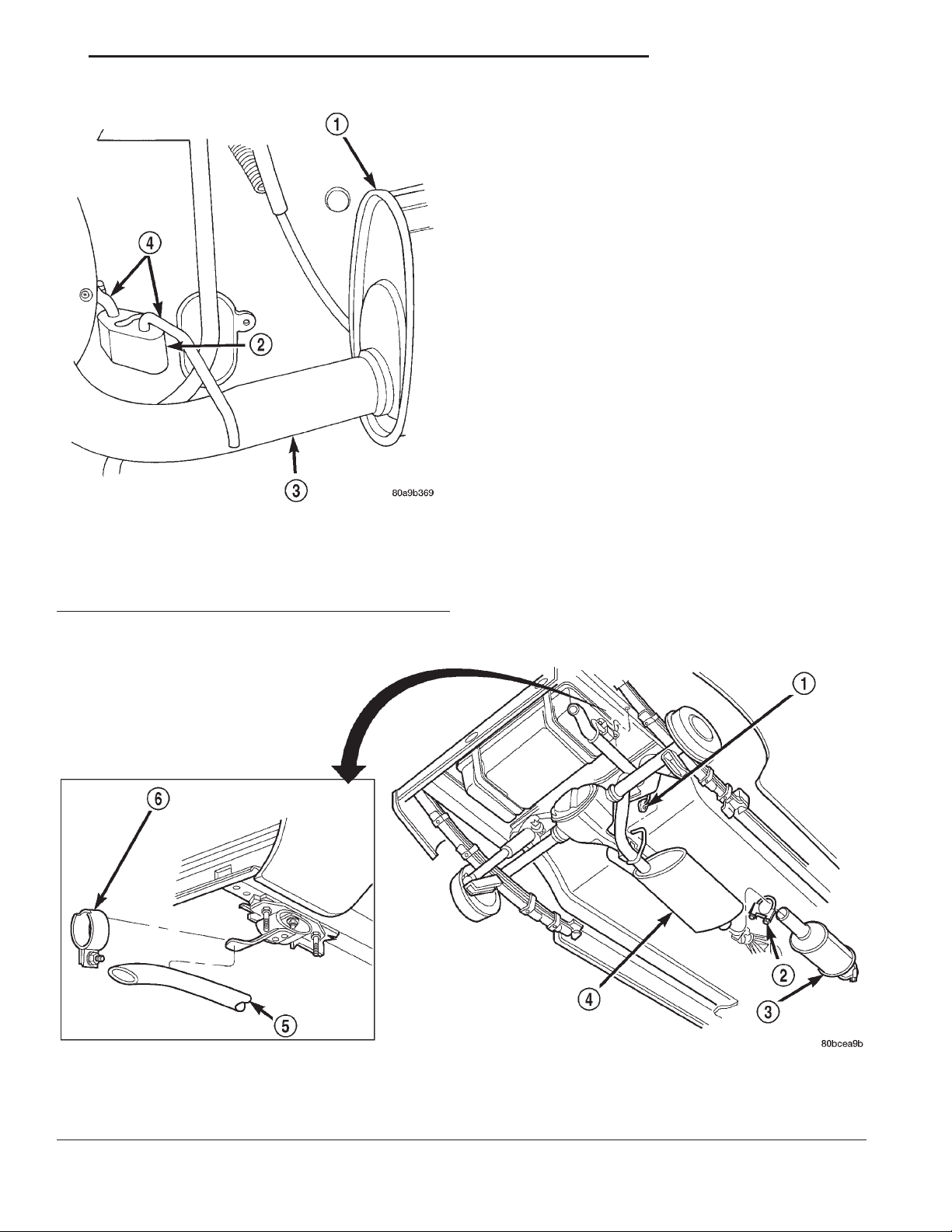
(2) Disconnect front tailpipe hanger from the insu-
lator (Fig. 10).
(3) Remove the front exhaust clamp from the cat-
alytic converter and muffler connection (Fig. 11).
(4) Heat the catalytic converter-to-muffler connection with an oxyacetylene torch until the metal
becomes cherry red.
(5) While the metal is still cherry red, remove the
exhaust muffler/tailpipe assembly from the catalytic
converter.
(6) Slide the muffler/tailpipe assy. rearward and
out of the rear exhaust tailpipe mounting bracket
(Fig. 11).
Page 7
XJ EXHAUST SYSTEM 11 - 7
REMOVAL AND INSTALLATION (Continued)
• To remove an original equipment exhaust muffler/tailpipe combination, cut the exhaust tailpipe
close to the muffler. Collapse the part remaining in
the muffler and remove.
• To remove a service exhaust tailpipe/muffler
combination, apply heat until the metal becomes
cherry red. Remove the exhaust tailpipe/muffler
clamp and twist the exhaust tailpipe out of the muffler.
INSTALLATION
(1) Install the muffler onto the catalytic converter.
Install the clamp and tighten the nut finger tight.
(2) Install the exhaust tailpipe into the rear of the
muffler.
(3) Install the exhaust tailpipe/muffler assembly
on the rear exhaust tailpipe mounting bracket. Make
sure that the exhaust tailpipe has sufficient clearance from the floor pan.
(4) Install front tailpipe hanger into the insulator
(Fig. 10).
(5) Align the muffler and tighten the nuts on the
Fig. 10 Front Exhaust Tailpipe Hanger
1 – MUFFLER
2 – INSULATOR
3 – TAILPIPE
4 – FRONT TAILPIPE HANGER
(7) Remove the muffler from the exhaust tailpipe:
muffler-to-catalytic converter clamp to 61 N·m (45 ft.
lbs.) torque (Fig. 11).
(6) Align the tailpipe and install a new clamp at
the muffler to tailpipe connection.
(7) Tighten the muffler to tailpipe clamp to 61 N·m
(45 ft. lbs.)
(8) Lower the vehicle.
Fig. 11 Muffler/Tailpipe Removal and Installation
1 – MUFFLER AND TAIL PIPE HANGER
2 – CLAMP
3 – CATALYTIC CONVERTER
4 – MUFFLER AND TAIL PIPE ASSEMBLY
5 – TAIL PIPE
6 – TAIL PIPE HANGER CLAMP
Page 8
11 - 8 EXHAUST SYSTEM XJ
REMOVAL AND INSTALLATION (Continued)
(9) Start the engine and inspect for exhaust leaks
and exhaust system contact with the body panels.
Adjust the alignment, if needed.
HEAT SHIELDS
REMOVAL
(1) Raise and support the vehicle.
(2) Remove the screws and/or nuts holding the
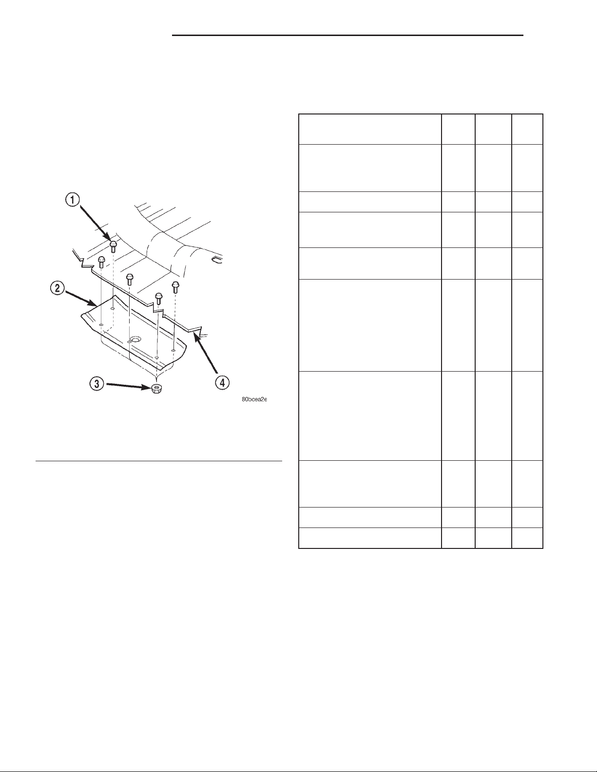
heat shields to the frame and/or floor pan (Fig. 12).
SPECIFICATIONS
TORQUE SPECIFICATIONS
DESCRIPTION N·m Ft. In.
Lbs. Lbs.
Catalytic Converter/Exhaust
Pipe
Exhaust Clamp—Nuts 61 45 —
Crossmember to Sill—Bolts 42 31 —
Crossmember to Transmission
Mount—Nuts 22 16 —
Exhaust Pipe to Manifold—
Nuts
Exhaust Manifold to Engine
2.5L
Engine—
Bolt #1 41 40 —
Bolts #2–5 31 23 —
Nuts #6&7 31 23 —
31 23 —
Fig. 12 Heat Shield Removal/Installation
1 – BOLTS
2 – MUFFLER HEAT SHIELD
3 – NUTS
4 – FLOOR PAN
(3) When removing muffler heat shield, the muf-
fler front support bracket must be removed first.
(4) Slide the shields out around the exhaust sys-
tem.
INSTALLATION
(1) Position the heat shields to the floor pan or the
frame and install the screws and/or nuts.
(2) Tighten the nuts and/or screws to 45 N·m (33
ft. lbs.) (Fig. 12).
(3) Lower the vehicle.
Exhaust Manifold to Engine
4.0L
Engine—
Nuts #6&7 31 23 —
Nuts/Bolts
#1,2,3,4,5,8,9,10&11
Muffler to Catalytic
Converter—
Exhaust Clamp Nut 61 45 —
Oxygen Sensors 27 20 —
Rear Tail Pipe Hanger—Nuts 54 40 —
33 24 —
 Loading...