

Page 1

PL ENGINE 9 - 1
ENGINE
CONTENTS
page page
2.0L DOHC ENGINE ..................... 52
2.0L SOHC ENGINE ..................... 12
STANDARD SERVICE PROCEDURES
INDEX
page page
GENERAL INFORMATION
CHECKING ENGINE OIL LEVEL ............. 5
CRANKSHAFT SPROCKET BOLT ACCESS
PLUG ............................... 2
ENGINE CORE PLUGS ................... 2
ENGINE OIL SERVICE .................... 5
ENGINE PERFORMANCE ................. 2
GENERAL INFORMATION
FORM-IN-PLACE GASKETS
There are numerous places where form-in-place
gaskets are used on the engine. Care must be taken
when applying form-in-place gaskets to assure
obtaining the desired results. Do not use form-in-
place gasket material unless specified. Bead size,
continuity, and location are of great importance. Too
thin a bead can result in leakage while too much can
result in spill-over which can break off and obstruct
fluid feed lines. A continuous bead of the proper
width is essential to obtain a leak-free gasket.
There are numerous types of form-in-place gasket
materials that are used in the engine area. Mopar
Silicone Rubber Adhesive Sealant and Mopar Gasket
Maker gasket materials, each have different properties and can not be used in place of the other.
MOPAR SILICONE RUBBER ADHESIVE
SEALANT
Mopar Silicone Rubber Adhesive Sealant or equivalent, normally black in color, is available in three
ounce tubes. Moisture in the air causes the Mopar
Silicone Rubber Adhesive Sealant material to cure.
This material is normally used on flexible metal
flanges. It has a shelf life of one year and will not
properly cure if over age. Always inspect the package
for the expiration date before use.
ENGINE DIAGNOSIS ...................... 7
STANDARD SERVICE PROCEDURES ......... 1
FORM-IN-PLACE GASKETS ................ 1
HONING CYLINDER BORES ............... 3
HYDROSTATIC LOCKED ENGINE ........... 5
MEASURING MAIN BEARING AND
CONNECTING ROD BEARING
CLEARANCES ........................ 3
REPAIR OF DAMAGED OR WORN THREADS . . 5
MOPAR GASKET MAKER
Mopar Gasket Maker is an anaerobic type gasket
material. The material cures in the absence of air
when squeezed between two metallic surfaces. It will
not cure if left in the uncovered tube. The anaerobic
material is for use between two machined surfaces.
Do not use on flexible metal flanges.
MOPAR TORQUE CURE GASKET MAKER
Mopar Torque Cure Gasket Maker is a unique
anaerobic type gasket material to be used ONLY
between the bedplate and engine block. The material
cures in the absence of air when torqued between
two metallic surfaces. It will not cure if left in the
uncovered tube. This anaerobic material is specially
made to seal the area between the bedplate and cylinder block without disturbing the bearing clearance
or alignment of these components.
GASKET DISASSEMBLY
Parts assembled with form-in-place gaskets may be
disassembled without unusual effort. In some
instances, it may be necessary to lightly tap the part
with a mallet or other suitable tool to break the seal
between the mating surfaces. A flat gasket scraper
may also be lightly tapped into the joint but care
must be taken not to damage the mating surfaces.
SURFACE PREPARATION
Scrape clean or wire brush all gasket surfaces
removing all loose material. Inspect stamped parts to
Page 2
CYLINDERBLOCK SECOND REMOVE PLUGWITH PLIERSFIRST STRIKE HEREWITH HAMMERDRIFTCUP PLUG
9 - 2 ENGINE PL
GENERAL INFORMATION (Continued)
assure gasket rails are flat. Flatten rails with a hammer on a heavy steel plate if required. Gasket surfaces must be free of oil and dirt. Make sure old
gasket material is removed from blind attaching
holes.
FORM-IN-PLACE GASKET APPLICATION
Assembling parts using a form-in-place gasket
requires care but it’s easier then using precut gaskets.
Mopar Gasket Maker material should be applied
sparingly 1 mm(0.040 inch.) diameter or less of sealant to one gasket surface. Be certain the material
surrounds each mounting hole. Excess material can
easily be wiped off. Components should be torqued in
place within 15 minutes. The use of a locating dowel
is recommended during assembly to prevent smearing material off the location.
The Mopar Silicone Rubber Adhesive Sealant gasket material or equivalent should be applied in a continuous bead approximately 3 mm (0.120 inch) in
diameter. All mounting holes must be circled. For
corner sealing, a 3.17 or 6.35 mm (1/8 or 1/4 inch.)
drop is placed in the center of the gasket contact
area. Uncured sealant may be removed with a shop
towel. Components should be torqued in place while
the sealant is still wet to the touch (within 10 minutes). The usage of a locating dowel is recommended
during assembly to prevent smearing material off the
location.
CRANKSHAFT SPROCKET BOLT ACCESS PLUG
An Access plug is located in the right inner fender
shield. Remove the plug and insert the proper size
socket, extension and ratchet, when crankshaft rotation is necessary.
ENGINE CORE PLUGS
REMOVAL
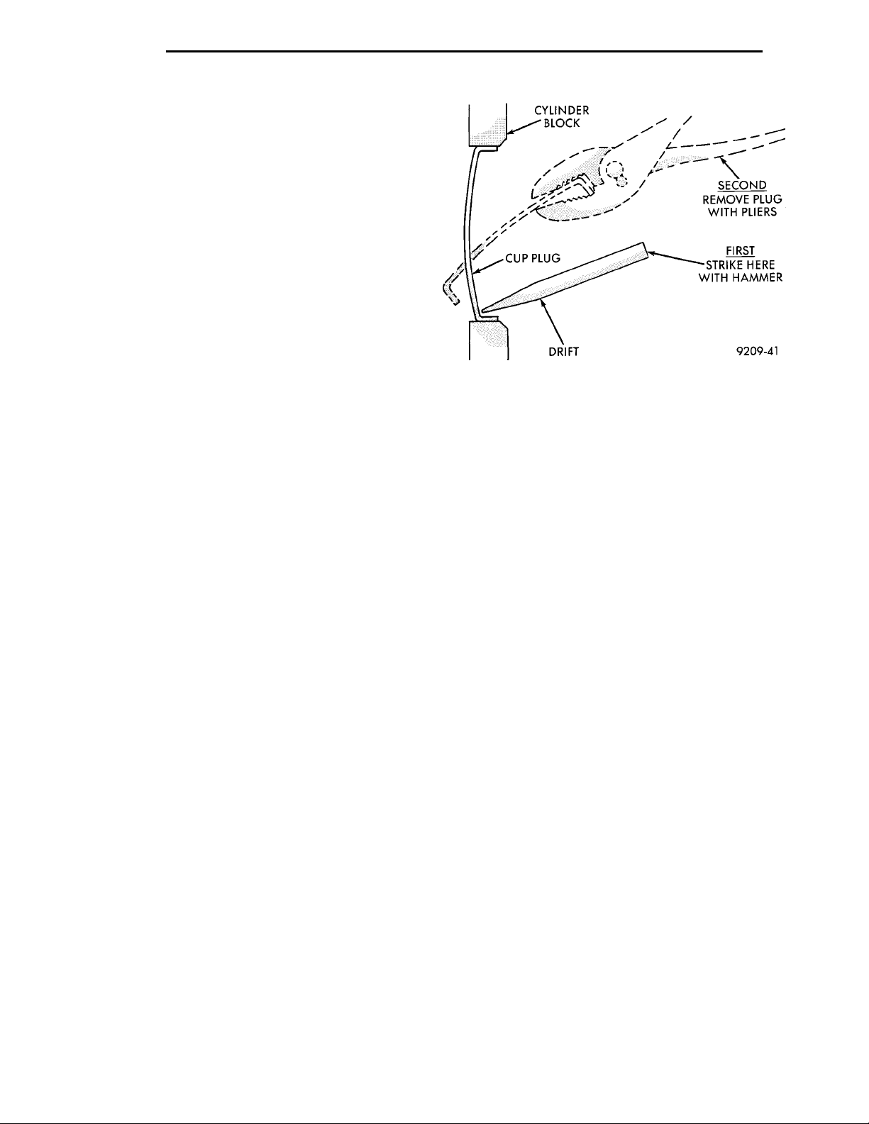
Using a blunt tool such as a drift or a screwdriver
and a hammer, strike the bottom edge of the cup
plug (Fig. 1). With the cup plug rotated, grasp firmly
with pliers or other suitable tool and remove plug
(Fig. 1).
CAUTION: Do not drive cup plug into the casting
as restricted cooling can result and cause serious
engine problems.
INSTALLATION
Thoroughly remove all rust and clean inside of cup
plug hole in cylinder block or head. Be sure to
remove old sealer. Lightly coat inside of cup plug hole
with sealer. Make certain the new plug is cleaned of
all oil or grease. Using proper drive plug, drive plug
into hole so that the sharp edge of the plug is at
least 0.5 mm (0.020 inch.) inside the lead in chamfer
(Fig. 1).
It is in not necessary to wait for curing of the sealant. The cooling system can be refilled and the vehicle placed in service immediately.
ENGINE PERFORMANCE
If a loss of performance is noticed, ignition timing
should be checked. timing belt or chain may have
skipped one or two teeth. Camshaft and crankshaft
timing should also be checked. Refer to Group 9,
Engine Timing belt or chain installation.
To provide best vehicle performance and lowest
vehicle emissions, it is most important that the
tune-up be done accurately. Use the specifications
listed on the Vehicle Emission Control Information
label found in the engine compartment.
(1) Test cranking amperage draw. See Starting
Motor Cranking Amperage Draw Electrical Section of
this manual.
(2) Check intake manifold for vacuum leaks.
PERFORM CYLINDER COMPRESSION TEST
(1) Check engine oil level and add oil if necessary.
(2) Drive the vehicle until engine reaches normal
operating temperature. Select a route free from traffic and other forms of congestion, observe all traffic
laws, and accelerate through the gears several times
briskly.
(3) Remove all spark plugs from engine. As spark
plugs are being removed, check electrodes for abnormal firing indicators fouled, hot, oily, etc. Record cylinder number of spark plug for future reference.
(4) Disconnect coil wire from distributor and
secure to good ground to prevent a spark from starting a fire (Conventional Ignition System). For Direct
Ignition System DIS disconnect the coil connector.
(5) Be sure throttle blade is fully open during the
compression check.
Fig. 1 Core Hole Plug Removal
Page 3
CROSS-HATCHPATTERN
PL ENGINE 9 - 3
GENERAL INFORMATION (Continued)
(6) Insert compression gage adaptor into the #1
spark plug hole in cylinder head. Crank engine until
maximum pressure is reached on gage. Record this
pressure as #1 cylinder pressure.
(7) Repeat the previous step for all remaining cylinders.
(8) Compression should not be less than (689kPa)
100 psi and not vary more than 25 percent from cylinder to cylinder.
(9) If one or more cylinders have abnormally low
compression pressures, repeat the compression test.
(10) If the same cylinder or cylinders repeat an
abnormally low reading on the second compression
test, it could indicate the existence of a problem in
the cylinder in question. The recommended com-
pression pressures are to be used only as a
guide to diagnosing engine problems. An engine
should not be disassembled to determine the
cause of low compression unless some malfunction is present.
(11) Clean or replace spark plugs as necessary
and adjust gap as specified in Group 8, Electrical.
Tighten to specifications.
(1) Test resistance of spark plug cables. Refer to
Group 8, Electrical Ignition System Secondary Circuit Inspection.
(2) Test coil output voltage, primary and secondary resistance. Replace parts as necessary. Refer to
Group 8, Electrical Ignition System.
(3) Check fuel pump pressure at idle and different
RPM ranges. Refer to Group 14, Fuel System for
Specifications.
(4) The air filter elements should be replaced as
specified in Group 0, Lubrication and Maintenance,.
(5) Inspect crankcase ventilation system as out
lined in Group 0, Lubrication and Maintenance. For
emission controls see Group 25, Emission Controls
for service procedures.
(6) Inspect and adjust accessory belt drives referring to Group 7, Cooling System, Accessory Drive
Belts for proper adjustments.
(7) Road test vehicle as a final test.
HONING CYLINDER BORES
(1) Used carefully, the cylinder bore resizing hone
C-823 equipped with 220 grit stones, is the best tool
for this job. In addition to deglazing, it will reduce
taper and out-of-round as well as removing light
scuffing, scoring or scratches. Usually a few strokes
will clean up a bore and maintain the required limits.
(2) Deglazing of the cylinder walls may be done
using a cylinder surfacing hone, Tool C-3501,
equipped with 280 grit stones, if the cylinder bore is
straight and round. 20-60 strokes depending on the
bore condition, will be sufficient to provide a satisfac-
tory surface. Inspect cylinder walls after each 20
strokes, using a light honing oil. Do not use engine
or transmission oil, mineral spirits or kerosene.
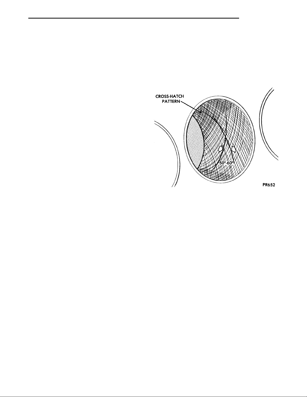
(3) Honing should be done by moving the hone up
and down fast enough to get a cross-hatch pattern.
When hone marks intersect at 50-60 degrees, the
cross hatch angle is most satisfactory for proper seating of rings (Fig. 2).
Fig. 2 Cylinder Bore Cross-Hatch Pattern
(4) A controlled hone motor speed between
200-300 RPM is necessary to obtain the proper crosshatch angle. The number of up and down strokes per
minute can be regulated to get the desired 50-60
degree angle. Faster up and down strokes increase
the cross-hatch angle.
(5) After honing, it is necessary that the block be
cleaned again to remove all traces of abrasive.
CAUTION: Ensure all abrasives are removed from
engine parts after honing. It is recommended that a
solution of soap and hot water be used with a
brush and the parts then thoroughly dried. The bore
can be considered clean when it can be wiped
clean with a white cloth and cloth remains clean.
Oil the bores after cleaning to prevent rusting.
MEASURING MAIN BEARING AND CONNECTING ROD BEARING CLEARANCES
PLASTIGAGE METHOD
Engine crankshaft bearing clearances can be determined by use of Plastigage or equivalent. The following is the recommended procedure for the use of
Plastigage:
Page 4
PLASTIGAGE
9 - 4 ENGINE PL
GENERAL INFORMATION (Continued)
Fig. 3 Plastigage Placed in Lower Shell
NOTE: The total clearance of the main bearings
can only be determined by removing the weight of
the crankshaft. This can be accomplished by either
of two methods:
PREFERRED METHOD
Shimming the bearings adjacent to the bearing to
be checked in order to remove the clearance between
upper bearing shell and the crankshaft. This can be
accomplished by placing a minimum of 0.254 mm
(0.010 in.) shim (e. g. cardboard, matchbook cover,
etc.) between the bearing shell and the bearing cap
on the adjacent bearings and tightening bolts to
14-20 N·m (10-15 ft. lbs.). The number of main bearing will vary from engine to engine.
ENGINE WITH 5 MAIN BEARINGS
• When checking #1 main bearing shim #2 main
bearing.
• When checking #2 main bearing shim #1 & 3
main bearing.
• When checking #3 main bearing shim #2 & 4
main bearing.
• When checking #4 main bearing shim #3 & 5
main bearing.
• When checking #5 main bearing shim #4 main
bearing.
ENGINE WITH 4 MAIN BEARING
• When checking #1 main bearing shim # 2 main
bearing.
• When checking #2 main bearing shim #1 & #3
main bearing.
• When checking #3 main bearing shim #2 & #4
main bearing.
• When checking #4 main bearing shim #3 main
bearing.
NOTE: REMOVE ALL SHIMS BEFORE REASSEMBLING ENGINE
Fig. 4 Clearance Measurement
ALTERNATIVE METHOD
The weight of the crankshaft can be supported by a
jack under the counterweight adjacent to the bearing
being checked.
PLASTIGAGE PROCEDURE
(1) Remove oil film from surface to be checked.
Plastigage is soluble in oil.
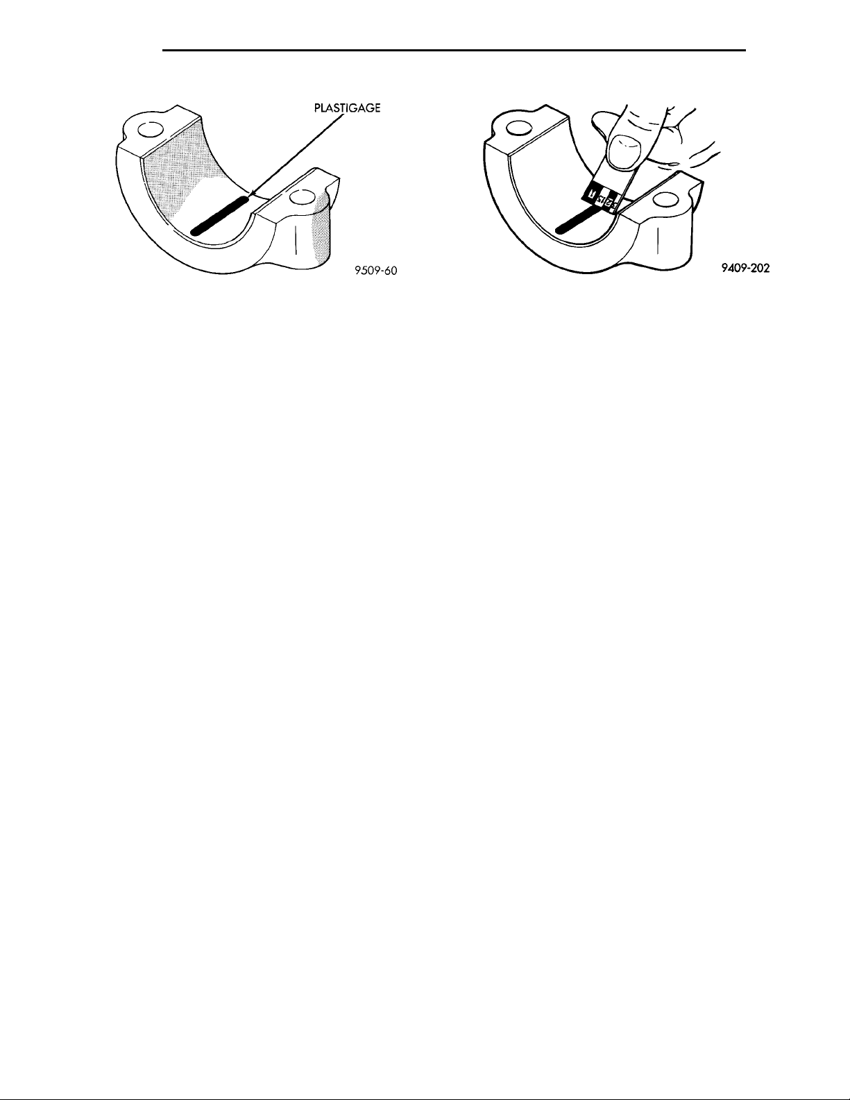
(2) Place a piece of Plastigage across the entire
width of the bearing shell in the cap approximately
6.35 mm (1/4 in.) off center and away from the oil
holes (Fig. 3). (In addition, suspected areas can be
checked by placing the Plastigage in the suspected
area). Torque the bearing cap bolts of the bearing
being checked to the proper specifications.
(3) Remove the bearing cap and compare the
width of the flattened Plastigage (Fig. 4) with the
metric scale provided on the package. Locate the
band closest to the same width. This band shows the
amount of clearance in thousandths of a millimeter.
Differences in readings between the ends indicate the
amount of taper present. Record all readings taken.
Refer to Engine Specifications. Plastigage gener-
ally is accompanied by two scales. One scale is
in inches, the other is a metric scale.
NOTE: Plastigage is available in a variety of clearance ranges. Use the most appropriate range for
the specifications you are checking.
CONNECTING ROD BEARING CLEARANCE
Engine connecting rod bearing clearances can be
determined by use of Plastigage or equivalent. The
following is the recommended procedure for the use
of Plastigage:
(1) Rotate the crankshaft until the connecting rod
to be checked is at the bottom of its stroke.
(2) Remove oil film from surface to be checked.
Plastigage is soluble in oil.
(3) Place a piece of Plastigage across the entire
width of the bearing shell in the bearing cap approximately 6.35 mm (1/4 in.) off center and away from
Page 5
ENGINE OIL LEVEL DIP-STICK
PL ENGINE 9 - 5
GENERAL INFORMATION (Continued)
the oil hole (Fig. 3). In addition, suspect areas can be
checked by placing plastigage in the suspect area.
(4) Assemble the rod cap with Plastigage in place.
Tighten the rod cap to the specified torque. Do not
rotate the crankshaft while assembling the cap
or the Plastigage may be smeared, giving inaccurate results.
(5) Remove the bearing cap and compare the
width of the flattened Plastigage (Fig. 4) with the
scale provided on the package. Locate the band closest to the same width. This band indicates the
amount of oil clearance. Differences in readings
between the ends indicate the amount of taper
present. Record all readings taken. Refer to Engine
Specifications. Plastigage generally is accompa-
nied by two scales. One scale is in inches, the
other is a metric scale. If the bearing clearance
exceeds 0.076 mm (0.003 in.) replace bearing.
NOTE: Plastigage is available in a variety of clearance ranges. Use the most appropriate range for
the specifications you are checking.
REPAIR OF DAMAGED OR WORN THREADS
Damaged or worn threads (including aluminum
head spark plug threads) can be repaired. Essentially, this repair consists of drilling out worn or
damaged threads, tapping the hole with a special
Heli-Coil Tap, (or equivalent) and installing an insert
into the tapped hole. This brings the hole back to its
original thread size.
(5) Identify the fluid in the cylinder(s) (i.e., cool-
ant, fuel, oil or other).
(6) Make sure all fluid has been removed from the
cylinders. Inspect engine for damage (i.e., Connecting
Rods, Pistons, Valves etc.)
(7) Repair engine or components as necessary to
prevent this problem from occurring again.
CAUTION: Squirt approximately 1 teaspoon of oil
into cylinders, rotate engine to lubricate the cylinder walls to prevent damage on restart.
(8) Install new spark plugs.
(9) Drain engine oil and remove oil filter.
(10) Fill engine with specified amount of approved
oil and install new oil filter.
(11) Connect negative battery cable.
(12) Start engine and check for any leaks.
CHECKING ENGINE OIL LEVEL
The best time to check engine oil level is after it
has sat overnight, or if the engine has been running,
allow the engine to be shut off for at least 5 minutes
before checking oil level.
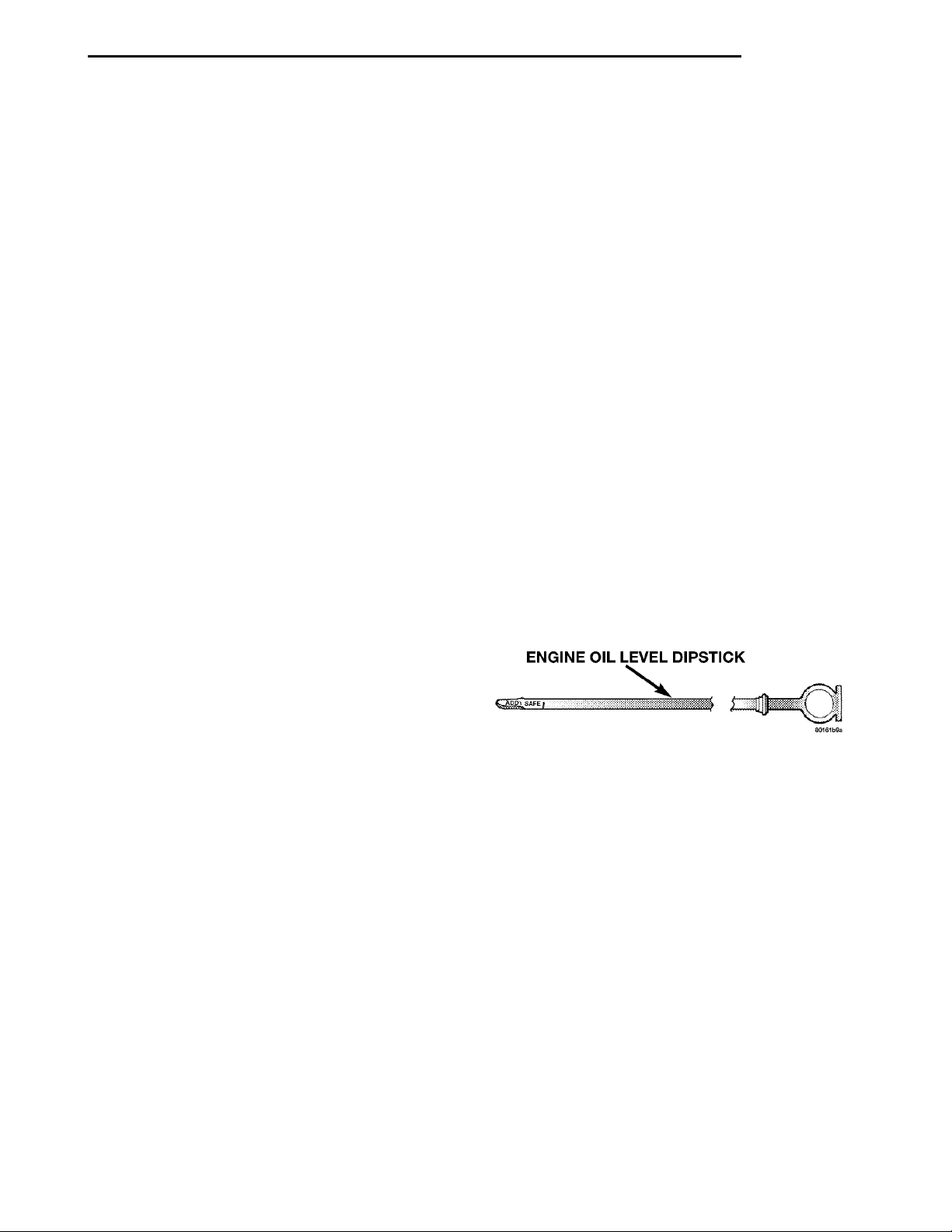
Checking the oil while the vehicle is on level
ground will improve the accuracy of the oil level
reading. Add only when the level is at or below the
ADD mark (Fig. 5).
CAUTION: Be sure that the tapped holes maintain
the original centerline.
Heli-Coil tools and inserts are readily available
from automotive parts jobbers.
HYDROSTATIC LOCKED ENGINE
When an engine is suspected to be hydrostatically
locked, regardless of what caused the problem, these
steps should be used.
CAUTION: Do Not Use Starter Motor To Rotate
Engine, severe damage may occur.
(1) Inspect air cleaner, induction system and
intake manifold to insure system is dry and clear of
foreign material.
(2) Remove negative battery cable.
(3) Place a shop towel around the spark plugs
when removing them from the engine. This will catch
any fluid that may possibly be in the cylinder under
pressure.
(4) With all spark plugs removed, rotate engine
crankshaft using a breaker bar and socket.
Fig. 5 Oil Level
ENGINE OIL SERVICE
WARNING: NEW OR USED ENGINE OIL CAN BE
IRRITATING TO THE SKIN. AVOID PROLONGED OR
REPEATED SKIN CONTACT WITH ENGINE OIL.
CONTAMINANTS IN USED ENGINE OIL, CAUSED BY
INTERNAL COMBUSTION, CAN BE HAZARDOUS TO
YOUR HEALTH. THOROUGHLY WASH EXPOSED
SKIN WITH SOAP AND WATER. DO NOT WASH
SKIN WITH GASOLINE, DIESEL FUEL, THINNER, OR
SOLVENTS, HEALTH PROBLEMS CAN RESULT. DO
NOT POLLUTE, DISPOSE OF USED ENGINE OIL
PROPERLY. CONTACT YOUR DEALER OR GOVERNMENT AGENCY FOR LOCATION OF COLLECTION
CENTER IN YOUR AREA.
Page 6
ANTICIPATED TEMPERA-TURE RANGE BEFORENEXT OIL CHANGE
9 - 6 ENGINE PL
GENERAL INFORMATION (Continued)
ENGINE OIL SPECIFICATION
CAUTION: Do not use non-detergent or straight
mineral oil when adding or changing crankcase
lubricant. Engine failure can result.
API SERVICE GRADE CERTIFIED
Use an engine oil that is API Service Grade Certified or an oil that conforms to the API Service Grade
SH or SH/CD. MOPAR provides engine oils that conform to all of these service grades.
Fig. 7 Engine Oil Container Standard Notations
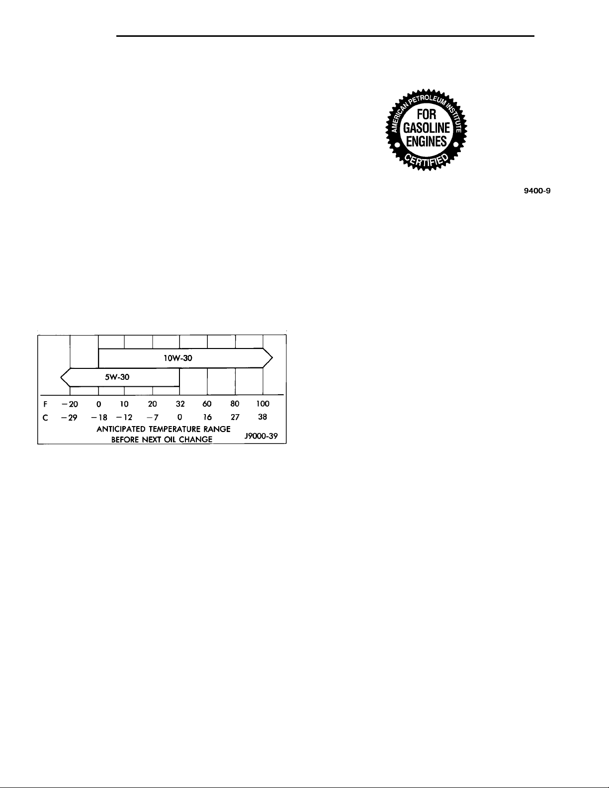
SAE VISCOSITY
An SAE viscosity grade is used to specify the viscosity of engine oil. SAE 30 specifies a single viscosity engine oil. Engine oils also have multiple
viscosities. These are specified with a dual SAE viscosity grade which indicates the cold-to-hot temperature viscosity range. Select an engine oil that is best
suited to your particular temperature range and variation (Fig. 6).
ENGINE OIL ADDITIVES
In some instances, such as infrequent operation,
short trip driving, and during break-in after a major
overhaul, addition of special materials containing
anti-rust and anti-scuff additives are beneficial. A
suitable product for this purpose is MOPAR Engine
Oil Supplement.
ENGINE OIL CHANGE
Change engine oil at mileage and time intervals
described in the Maintenance Schedule.
Fig. 6 Temperature/Engine Oil Viscosity
ENERGY CONSERVING OIL
An Energy Conserving type oil is recommended for
gasoline engines. They are designated as either
ENERGY CONSERVING or ENERGY CONSERVING II.
CONTAINER IDENTIFICATION
Standard engine oil identification notations have
been adopted to aid in the proper selection of engine
oil. The identifying notations are located on the label
of engine oil plastic bottles and the top of engine oil
cans (Fig. 7).
TO CHANGE ENGINE OIL
Run engine until achieving normal operating tem-
perature.
(1) Position the vehicle on a level surface and turn
engine off.
(2) Hoist and support vehicle on safety stands.
Refer to Hoisting and Jacking Recommendations.
(3) Remove oil fill cap.
(4) Place a suitable drain pan under crankcase
drain.
(5) Remove drain plug from crankcase and allow
oil to drain into pan. Inspect drain plug threads for
stretching or other damage. Replace drain plug and
gasket if damaged.
(6) Install drain plug in crankcase.
(7) Lower vehicle and fill crankcase with specified
type and amount of engine oil described in this section.
(8) Install oil fill cap.
(9) Start engine and inspect for leaks.
(10) Stop engine and inspect oil level.
Page 7

PL ENGINE 9 - 7
ENGINE DIAGNOSIS
INDEX
page page
DIAGNOSIS AND TESTING
CYLINDER COMBUSTION PRESSURE
LEAKAGE TEST ....................... 8
CYLINDER COMPRESSION PRESSURE TEST . 7
ENGINE DIAGNOSIS—MECHANICAL ........ 11
ENGINE DIAGNOSIS—PERFORMANCE ..... 10
DIAGNOSIS AND TESTING
GENERAL INFORMATION
Engine diagnosis is helpful in determining the
causes of malfunctions not detected and remedied by
routine tune-ups.
These malfunctions may be classified as either
mechanical (e.g., a strange noise), or performance
(e.g., engine idles rough and stalls).
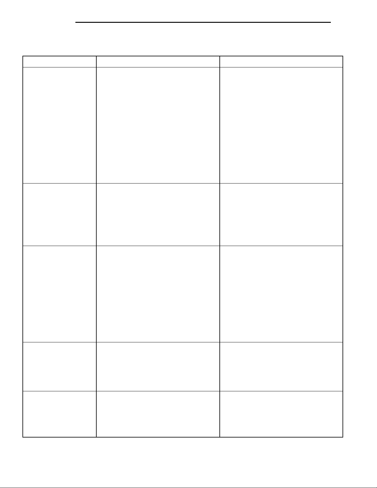
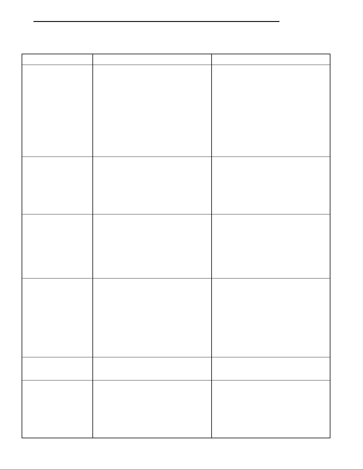
Refer to the Service Diagnosis—Mechanical Chart
and the Service Diagnosis—Performance Chart, for
possible causes and corrections of malfunctions. Refer
to Group 14, Fuel System, for the fuel system diagnosis.
Additional tests and diagnostic procedures may be
necessary for specific engine malfunctions that cannot be isolated with the Service Diagnosis charts.
Information concerning additional tests and diagnosis is provided within the following:
• Cylinder Compression Pressure Test
• Cylinder Combustion Pressure Leakage Test
• Engine Cylinder Head Gasket Failure Diagnosis
• Intake Manifold Leakage Diagnosis
INTAKE MANIFOLD LEAKAGE DIAGNOSIS
An intake manifold air leak is characterized by
lower than normal manifold vacuum. Also, one or
more cylinders may not be functioning.
WARNING: USE EXTREME CAUTION WHEN THE
ENGINE IS OPERATING. DO NOT STAND IN A
DIRECT LINE WITH THE FAN. DO NOT PUT YOUR
HANDS NEAR THE PULLEYS, BELTS OR THE FAN.
DO NOT WEAR LOOSE CLOTHING.
(1) Start the engine.
(2) Spray a small stream of water (Spray Bottle) at
the suspected leak area.
(3) If a change in RPM’S, the area of the suspected
leak has been found.
(4) Repair as required.
GENERAL INFORMATION ................. 7
INSPECTION (ENGINE OIL LEAKS IN
GENERAL) ........................... 8
INTAKE MANIFOLD LEAKAGE DIAGNOSIS .... 7
LASH ADJUSTER (TAPPET) NOISE
DIAGNOSIS .......................... 8
CYLINDER COMPRESSION PRESSURE TEST
The results of a cylinder compression pressure test
can be utilized to diagnose several engine malfunctions.
Ensure the battery is completely charged and the
engine starter motor is in good operating condition.
Otherwise the indicated compression pressures may
not be valid for diagnosis purposes.
(1) Check engine oil level and add oil if necessary.
(2) Drive the vehicle until engine reaches normal
operating temperature. Select a route free from traffic and other forms of congestion, observe all traffic
laws, and accelerate through the gears several times
briskly.
(3) Remove all spark plugs from engine. As spark
plugs are being removed, check electrodes for abnormal firing indicators fouled, hot, oily, etc. Record cylinder number of spark plug for future reference.
(4) Disconnect coil wire from distributor and
secure to good ground to prevent a spark from starting a fire (Conventional Ignition System). For Direct
Ignition System DIS disconnect the coil connector.
(5) Be sure throttle blade is fully open during the
compression check.
(6) Insert compression gage adaptor into the #1
spark plug hole in cylinder head. Crank engine until
maximum pressure is reached on gage. Record this
pressure as #1 cylinder pressure.
(7) Repeat the previous step for all remaining cylinders.
(8) Compression should not be less than (689kPa)
100 psi and not vary more than 25 percent from cylinder to cylinder.
(9) If one or more cylinders have abnormally low
compression pressures, repeat the compression test.
(10) If the same cylinder or cylinders repeat an
abnormally low reading on the second compression
test, it could indicate the existence of a problem in
the cylinder in question. The recommended com-
pression pressures are to be used only as a
guide to diagnosing engine problems. An engine
should not be disassembled to determine the
Page 8

9 - 8 ENGINE PL
DIAGNOSIS AND TESTING (Continued)
cause of low compression unless some malfunction is present.
(11) Clean or replace spark plugs as necessary
and adjust gap as specified in Group 8, Electrical.
Tighten to specifications.
(12) Test resistance of spark plug cables. Refer to
Group 8, Electrical Ignition System Secondary Circuit Inspection.
(13) Test coil output voltage, primary and secondary resistance. Replace parts as necessary. Refer to
Group 8, Electrical Ignition System.
(14) Check fuel pump pressure at idle and different RPM ranges. Refer to Group 14, Fuel System for
Specifications.
(15) The air filter elements should be replaced as
specified in Group 0, Lubrication and Maintenance,.
(16) Inspect crankcase ventilation system as out
lined in Group 0, Lubrication and Maintenance. For
emission controls see Group 25, Emission Controls
for service procedures.
(17) Inspect and adjust accessory belt drives referring to Group 7, Cooling System, Accessory Drive
Belts for proper adjustments.
(18) Road test vehicle as a final test.
CYLINDER COMBUSTION PRESSURE LEAKAGE TEST
The combustion pressure leakage test provides an
accurate means for determining engine condition.
Combustion pressure leakage testing will detect:
• Exhaust and intake valve leaks (improper seat-
ing).
• Leaks between adjacent cylinders or into water
jacket.
• Any causes for combustion/compression pressure
loss.
WARNING: DO NOT REMOVE THE RADIATOR CAP
WITH THE SYSTEM HOT AND UNDER PRESSURE
BECAUSE SERIOUS BURNS FROM COOLANT CAN
OCCUR.
Perform the test procedures on each cylinder
according to the tester manufacturer’s instructions.
While testing, listen for pressurized air escaping
through the throttle body, tailpipe and oil filler cap
opening. Check for bubbles in the radiator coolant.
All gauge pressure indications should be equal,
with no more than 25% leakage.
FOR EXAMPLE: At 552 kPa (80 psi) input pressure, a minimum of 414 kPa (60 psi) should be maintained in the cylinder.
LASH ADJUSTER (TAPPET) NOISE DIAGNOSIS
A tappet-like noise may be produced from several
items. Check the following items.
(1) Engine oil level too high or too low. This may
cause aerated oil to enter the adjusters and cause
them to be spongy.
(2) Insufficient running time after rebuilding cylinder head. Low speed running up to 1 hour may be
required.
(3) During this time, turn engine off and let set for
a few minutes before restarting. Repeat this several
times after engine has reached normal operating
temperature.
(4) Low oil pressure.
(5) The oil restrictor pressed into the vertical oil
passage to the cylinder head is plugged with debris.
(6) Air ingested into oil due to broken or cracked
oil pump pick up.
(7) Worn valve guides.
(8) Rocker arm ears contacting valve spring
retainer.
(9) Rocker arm loose, adjuster stuck or at maximum extension and still leaves lash in the system.
(10) Faulty lash adjuster.
a. Check lash adjusters for sponginess while
installed in cylinder head. Depress part of rocker
arm over adjuster. Normal adjusters should feel very
firm. Spongy adjusters can be bottomed out easily.
b. Remove suspected rocker arms (sohc) or lash
adjuster (dohc) and replace.
Check the coolant level and fill as required. DO
NOT install the radiator cap.
Start and operate the engine until it attains normal operating temperature, then turn the engine
OFF.
Clean spark plug recesses with compressed air.
Remove the spark plugs.
Remove the oil filler cap.
Remove the air cleaner.
Calibrate the tester according to the manufacturer’s instructions. The shop air source for testing
should maintain 483 kPa (70 psi) minimum, 1 379
kPa (200 psi) maximum and 552 kPa (80 psi) recommended.
INSPECTION (ENGINE OIL LEAKS IN GENERAL)
Begin with a through visual inspection of the
engine, particularly at the area of the suspected leak.
If an oil leak source is not readily identifiable, the
following steps should be followed:
(1) Do not clean or degrease the engine at this
time because some solvents may cause rubber to
swell, temporarily stopping the leak.
(2) Add an oil soluble dye (use as recommended by
manufacturer). Start the engine and let idle for
approximately 15 minutes. Check the oil dipstick to
make sure the dye is thoroughly mixed as indicated
with a bright yellow color under a black light.
Page 9

PL ENGINE 9 - 9
DIAGNOSIS AND TESTING (Continued)
(3) Using a black light, inspect the entire engine
for fluorescent dye, particularly at the suspected area
of oil leak. If the oil leak is found and identified,
repair per service manual instructions.
(4) If dye is not observed, drive the vehicle at various speeds for approximately 24km (15 miles), and
repeat inspection.
(5) If the oil leak source is not positively
identified at this time , proceed with the air leak
detection test method as follows:
(6) Disconnect the fresh air hose (makeup air) at
the cylinder head cover and plug or cap the nipple on
the cover.
(7) Remove the PCV valve hose from the cylinder
head cover. Cap or plug the PCV valve nipple on the
cover.
(8) Attach an air hose with pressure gauge and
regulator to the dipstick tube.
CAUTION: Do not subject the engine assembly to
more than 20.6 kpa (3 PSI) of test pressure.
(9) Gradually apply air pressure from 1 psi to 2.5
psi maximum while applying soapy water at the suspected source. Adjust the regulator to the suitable
test pressure that provide the best bubbles which
will pinpoint the leak source. If the oil leak is
detected and identified, repair per service manual
procedures.
(10) If the leakage occurs at the rear oil seal area,
refer to the section, Inspection for Rear Seal Area
Leak.
(11) If no leaks are detected, turn off the air supply and remove the air hose and all plugs and caps.
Install the PCV valve and breather cap hose. Proceed
to next step.
(12) Clean the oil off the suspect oil leak area
using a suitable solvent. Drive the vehicle at various
speeds approximately 24 km (15 miles). Inspect the
engine for signs of an oil leak by using a black light.
INSPECTION FOR REAR SEAL AREA LEAKS
Since it is sometimes difficult to determine the
source of an oil leak in the rear seal area of the
engine, a more involved inspection is necessary. The
following steps should be followed to help pinpoint
the source of the leak.
If the leakage occurs at the crankshaft rear oil seal
area:
(1) Disconnect the battery.
(2) Raise the vehicle.
(3) Remove torque converter or clutch housing
cover and inspect rear of block for evidence of oil.
Use a black light to check for the oil leak. If a leak is
present in this area remove transmission for further
inspection.
(a) Circular spray pattern generally indicates
seal leakage or crankshaft damage.
(b) Where leakage tends to run straight down,
possible causes are a porous block, oil galley cup
plug, bedplate to cylinder block mating surfaces
and seal bore. See proper repair procedures for
these items.
(4) If no leaks are detected, pressurized the crank-
case as outlined in the, Inspection (Engine oil Leaks
in general)
CAUTION: Do not exceed 20.6 kPa (3 psi).
(5) If the leak is not detected, very slowly turn the
crankshaft and watch for leakage. If a leak is
detected between the crankshaft and seal while
slowly turning the crankshaft, it is possible the
crankshaft seal surface is damaged. The seal area on
the crankshaft could have minor nicks or scratches
that can be polished out with emery cloth.
CAUTION: Use extreme caution when crankshaft
polishing is necessary to remove minor nicks and
scratches. The crankshaft seal flange is especially
machined to complement the function of the rear oil
seal.
(6) For bubbles that remain steady with shaft
rotation, no further inspection can be done until disassembled.
(7) After the oil leak root cause and appropriate
corrective action have been identified. Refer to Rear
Crankshaft Seals, for proper replacement procedures.
Page 10
9 - 10 ENGINE PL
DIAGNOSIS AND TESTING (Continued)
ENGINE DIAGNOSIS—PERFORMANCE
CONDITION POSSIBLE CAUSE CORRECTION
ENGINE WILL NOT
START
ENGINE STALLS OR
ROUGH IDLE
1. Weak battery. 1. Test battery specific gravity. Charge or
replace as necessary.
2. Corroded or loose battery connections. 2. Clean and tighten battery connections.
Apply a coat of light mineral grease to the
terminals.
3. Faulty starter. 3. Refer to Group 8A, Battery/Starter/Charging
System Diagnostics.
4. Moisture on ignition wires. 4. Wipe wires clean and dry.
5. Faulty ignition cables. 5. Replace any cracked or shorted cables.
6. Faulty coil or control unit. 6. Test and replace, if necessary (refer to
Group 8D, Ignition system).
7. Incorrect spark plug gap. 7. Set gap (refer to Group 8D, Ignition
System).
8. Dirt or water in fuel system. 8. Clean system and replace fuel filter.
9. Faulty fuel pump. 9. Install new fuel pump (refer to Group 14,
Fuel System).
1. Idle speed set too low. 1. Refer to Group 14, Fuel System.
2. Idle mixture too lean or too rich. 2. Refer to Group 14, Fuel System.
3. Leak in intake manifold. 3. Inspect intake manifold gasket and vacuum
hoses. Replace, if necessary (refer to Group
11, Exhaust System & Intake Manifold).
4. Incorrect ignition wiring. 4. Install correct wiring.
5. Faulty coil. 5. Test and replace, if necessary (refer to
Group 8D, Ignition System).
ENGINE LOSS OF
POWER
ENGINE MISSES ON
ACCELERATION
ENGINE MISSES AT
HIGH SPEED
1. Dirty or incorrectly gapped spark plugs. 1. Clean plugs and set gap (refer to Group 8D,
Ignition System).
2. Dirt or water in fuel system. 2. Clean system and replace fuel filter.
3. Faulty fuel pump. 3. Install new fuel pump.
4. Incorrect valve timing. 4. Correct valve timing.
5. Blown cylinder head gasket. 5. Install new cylinder head gasket.
6. Low compression. 6. Test compression of each cylinder.
7. Burned, warped or pitted valves. 7. Install new valves.
8. Plugged or restricted exhaust system. 8. Install new parts, as necessary.
9. Faulty ignition cables. 9. Replace any cracked or shorted cables.
10. Faulty coil. 10. Test and replace, as necessary (refer to
Group 8D, Ignition System).
1. Dirty or gap set too wide in spark plug. 1. Clean spark plugs and set gap (refer to
Group 8D, Ignition System).
2. Dirt in fuel system. 2. Clean fuel system.
3. Burned, warped or pitted valves. 3. Install new valves.
4. Faulty coil. 4. Test and replace, if necessary, (refer to
Group 8D, Ignition System).
1. Dirty or gap set too wide in spark plug. 1. Clean spark plugs and set gap (refer to
Group 8D, Ignition System).
2. Faulty coil. 2. Test and replace, as necessary (refer to
Group 8D, Ignition System).
3. Dirty injector. 3. Clean injectors.
4. Dirt or water in fuel system. 4. Clean system and replace fuel filter.
Page 11
PL ENGINE 9 - 11
DIAGNOSIS AND TESTING (Continued)
ENGINE DIAGNOSIS—MECHANICAL
CONDITION POSSIBLE CAUSES CORRECTION
NOISY VALVES 1. High or low oil level in crankcase. 1. Check for correct oil level (refer to Group 0,
2. Thin or diluted oil. 2. Change oil (refer to Group 0, Lubrication and
3. Low oil pressure. 3. Check engine oil level.
4. Dirt in tappets/lash adjusters. 4. Replace rocker arm/hydraulic lash adjuster
5. Worn rocker arms. 5. Inspect oil supply to rocker arms.
6. Worn tappets/lash adjusters. 6. Install new rocker arm/hydraulic lash adjuster
7. Worn valve guides. 7. Ream and install new valves with oversize
8. Excessive runout of valve seats on valve faces. 8. Grind valve seats and valves.
9. Missing adjuster pivot. 9. Replace rocker arm/hydraulic lash adjuster
CONNECTING ROD NOISE 1. Insufficient oil supply. 1. Check engine oil level (refer to Group 0,
2. Low oil pressure. 2. Check engine oil level. Inspect oil pump relief
3. Thin or diluted oil. 3. Change oil to correct viscosity.
4. Excessive bearing clearance. 4. Measure bearings for correct clearance. Repair
5. Connecting rod journal out-of-round. 5. Replace crankshaft or grind journals.
6. Misaligned connecting rods. 6. Replace bent connecting rods.
MAIN BEARING NOISE 1. Insufficient oil supply. 1. Check engine oil level (refer to Group 0,
2. Low oil pressure. 2. Check engine oil level. Inspect oil pump relief
3. Thin or diluted oil. 3. Change oil to correct viscosity.
4. Excessive bearing clearance. 4. Measure bearings for correct clearance. Repair
5. Excessive end play. 5. Check thrust bearing for wear on flanges.
6. Crankshaft journal out-of-round, worn. 6. Grind journals or replace crankshaft.
7. Loose flywheel or torque converter. 7. Tighten to correct torque.
OIL PRESSURE DROP 1. Low oil level. 1. Check engine oil level.
2. Faulty oil pressure sending unit. 2. Install new sending unit.
3. Low oil pressure. 3. Check sending unit and check main bearing oil
4. Clogged oil filter. 4. Install new oil filter.
5. Worn parts in oil pump. 5. Replace worn parts or pump.
6. Thin or diluted oil. 6. Change oil to correct viscosity.
7. Excessive bearing clearance. 7. Measure bearings for correct clearance.
8. Oil pump relief valve stuck. 8. Remove valve and inspect, clean and install.
9. Oil pump suction tube loose, bent cracked, or
blocked.
10. Oil pump cover warped or cracked. 10. Install new oil pump.
OIL LEAKS 1. Misaligned or deteriorated gaskets. 1. Replace the gasket.
2. Loose fastener, broken or porous metal part. 2. Tighten, repair or replace the part.
3. Misaligned or deteriorated cup or threaded plug. 3. Replace.
OIL CONSUMPTION OR
SPARK PLUGS OIL FOULED
1. PCV system malfunction. 1. Check system. Clean and repair, as necessary
2. Worn, scuffed or broken rings. 2. Hone cylinder bores. Install new rings.
3. Carbon in oil ring slot. 3. Install new rings.
4. Rings fitted too tightly in grooves. 4. Remove the rings. Check grooves. If groove is
5. Worn valve guides. 5. Ream guides and replace valves with oversize
6. Valve stem seal unseated or defective. 6. Repair or replace seal.
Lubrication and Maintenance).
Maintenance).
assembly.
assembly.
stems.
assembly.
Lubrication and Maintenance).
valve and spring.
as necessary.
Lubrication and Maintenance).
valve and spring.
as necessary.
clearance.
9. Remove oil pan and install new tube, or clean if
necessary.
(refer to Group 25, Emissions Control System).
not proper width, replace piston.
valves and seals.
Page 12
ENGINE IDENTIFI-
CATION LOCATION
9 - 12 2.0L SOHC ENGINE PL
2.0L SOHC ENGINE
INDEX
page page
DESCRIPTION AND OPERATION
ENGINE COMPONENTS ................. 14
ENGINE IDENTIFICATION ................ 12
ENGINE LUBRICATION SYSTEM ........... 13
GENERAL SPECIFICATION ............... 12
DIAGNOSIS AND TESTING
CHECKING ENGINE OIL PRESSURE ........ 14
SERVICE PROCEDURES
CRANKSHAFT END PLAY ................ 17
CYLINDER BORE AND PISTON SIZING ...... 15
FITTING CONNECTING RODS ............. 15
FITTING CRANKSHAFT BEARINGS ......... 17
FITTING PISTON RINGS ................. 15
REMOVAL AND INSTALLATION
CAMSHAFT OIL SEAL ................... 27
CAMSHAFT ........................... 21
CRANKSHAFT ......................... 34
CYLINDER HEAD COVER ................ 20
CYLINDER HEAD ....................... 24
ENGINE ASSEMBLY ..................... 19
FRONT CRANKSHAFT OIL SEAL ........... 32
FRONT MOUNT ........................ 17
LEFT MOUNT .......................... 18
OIL FILTER ADAPTER ................... 36
OILFILTER ........................... 36
OILPAN .............................. 31
OIL PUMP ............................ 37
PISTON AND CONNECTING ROD .......... 38
POWER HOP DAMPER .................. 18
REAR CRANKSHAFT SEAL ............... 33
RIGHT MOUNT ........................ 18
ROCKER ARM/HYDRAULIC LASH
ADJUSTER .......................... 22
SPARK PLUG TUBE ..................... 21
TIMING BELT COVER ................... 25
TIMING BELT SYSTEM .................. 28
VALVE SEALS AND SPRINGS IN VEHICLE . . . 23
VIBRATION DAMPER .................... 40
DISASSEMBLY AND ASSEMBLY
OIL PUMP ............................ 41
VALVE SERVICE WITH THE CYLINDER
HEAD REMOVED ..................... 42
CLEANING AND INSPECTION
CYLINDER BLOCK AND BORE ............ 46
CYLINDER HEAD AND CAMSHAFT =
JOURNALS .......................... 44
OIL PUMP ............................ 45
SPECIFICATIONS
ENGINE 2.0L SOHC ..................... 47
TORQUE CHART 2.0L SOHC .............. 48
SPECIAL TOOLS
ENGINE 2.0L SOHC ..................... 49
DESCRIPTION AND OPERATION
ENGINE IDENTIFICATION
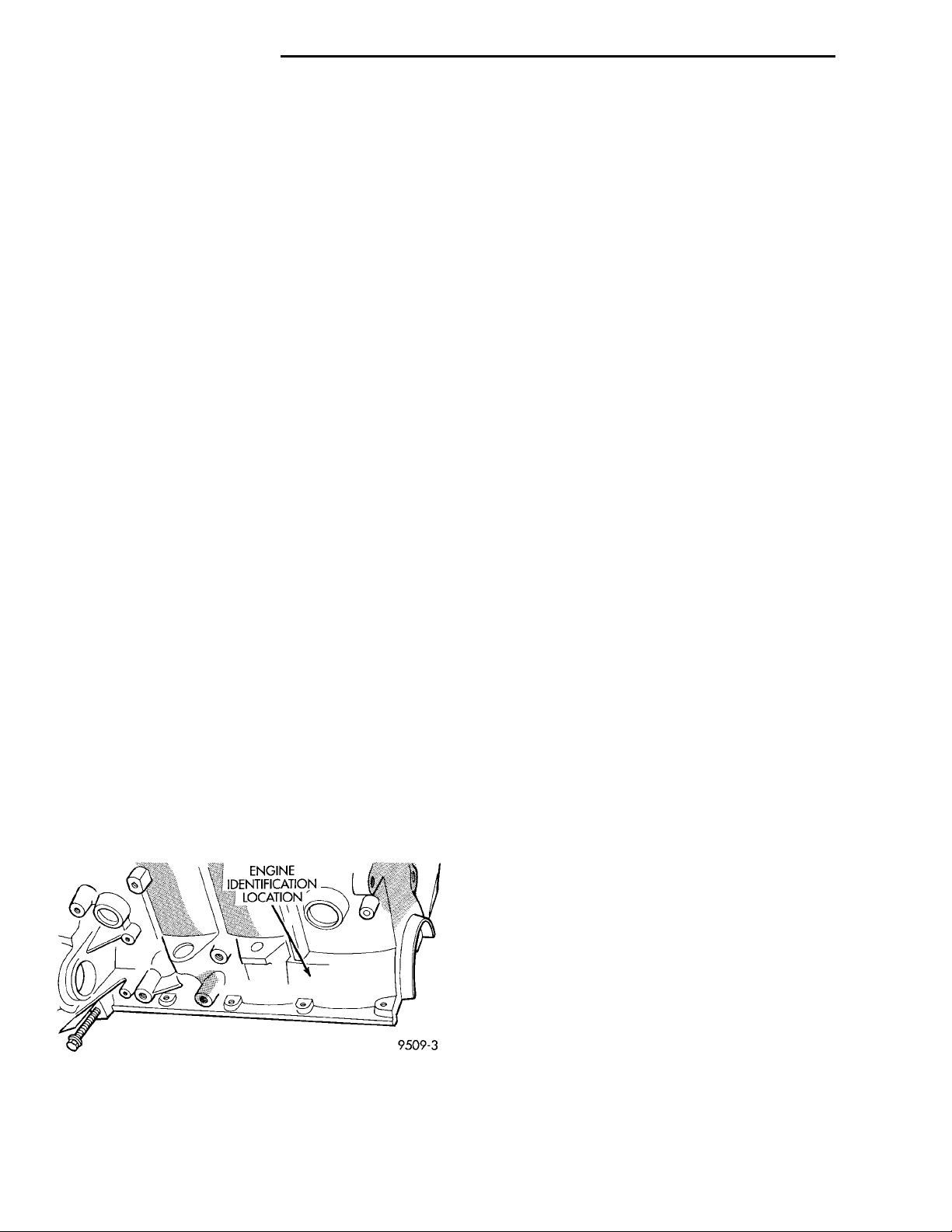
The engine identification number is located on the
left rear of the cylinder block behind starter (Fig. 1).
Fig. 1 Engine Identification SOHC
GENERAL SPECIFICATION
Type .............In-Line OHV, DOHC & SOHC
Bore .....................87.5mm (3.445 Inch)
Stroke ...................83.0mm (3.268 inch)
Compression Ratio ....DOHC - 9.6:1 SOHC - 9.8:1
Displacement .........2.0Liters (122 Cubic Inch)
Firing Order ........................1,3,4,2
Compression Pressure ...........1172-1551 kPa
(170 - 225 psi)
Maximum Variation Between
Cylinders ............................25%
Lubrication ...................Pressure Feed -
Full Flow Filtration
(Crankshaft Driven Pump)
Engine Oil Capacity
With Oil Filter Change .......4.25 Liter (4.5 Qts.)
Without Oil Filter Change .....3.8Liter (4.0 Qts.)
Page 13
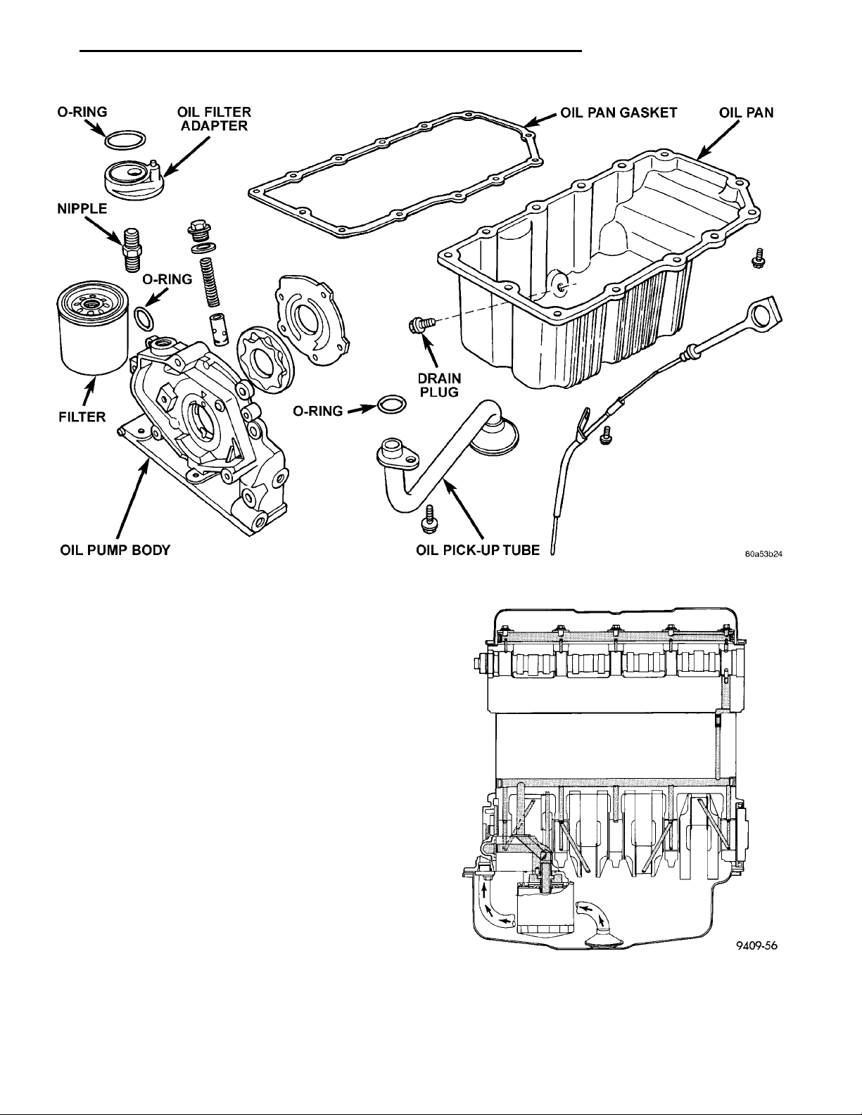
O-RINGOIL FILTER ADAPTEROIL PAN GASKETOIL PANOIL PICK-UP TUBEDRAIN PLUGO-RINGOIL PUMP BODYFILTERO-RINGNIPPLE
PL 2.0L SOHC ENGINE 9 - 13
DESCRIPTION AND OPERATION (Continued)
Engine Lubrication Components
ENGINE LUBRICATION SYSTEM
ENGINE LUBRICATION
Refer to Group 0, Lubrication and Maintenance for
recommended oil to be used in various engine application. System is full flow filtration, pressure feed
type. The oil pump is mounted in the front engine
cover and driven by the crankshaft. Pressurized oil is
then routed through the main oil gallery, running the
length of the cylinder block, supplying main and rod
bearings with further routing. Rod bearing oil throwoff lubricates the pistons from directed slots on the
side of the connecting rod assemblies. Camshaft and
valve mechanisms are lubricated from a full-length
cylinder head oil gallery supplied from the crankcase
main oil gallery.
PRESSURE LUBRICATION
Oil drawn up through the pickup tube is pressurized by the pump and routed through the full flow filter to the main oil gallery running the length of the
cylinder block. A cylinder head restrictor, located in
the block, provides increased oil flow to the main oil
gallery (Fig. 2).
Fig. 2 Engine Lubrication System— SOHC
MAIN/ROD BEARINGS
A diagonal hole in each bulkhead feeds oil to each
main bearing. Drilled passages within the crankshaft
Page 14

9 - 14 2.0L SOHC ENGINE PL
DESCRIPTION AND OPERATION (Continued)
route oil from main bearing journals to connecting
rod journals.
CAMSHAFT/HYDRAULIC LASH ADJUSTERS
A vertical hole at the number five bulkhead routes
pressurized oil through a restrictor up into the cylinder head. The rocker shafts route oil to the rocker
arms/hydraulic lash adjuster assemblies.
SPLASH LUBRICATION
Oil returning to the pan from pressurized components supplies lubrication to the valve stems. Cylinder bores and wrist pins are splash lubricated from
directed slots on the connecting rod thrust collars.
ENGINE COMPONENTS
CYLINDER BLOCK AND BEDPLATE ASSEMBLY A partial open deck is used for cooling and
weight reduction with water pump molded into the
block. Nominal wall thickness is 4 mm. The bedplate
incorporates main bearing caps. Rear seal retainer is
integral with the block.
CRANKSHAFT A nodular cast iron crankshaft is
used. The engine has 5 main bearings, with number
3 flanged to control thrust. The 52 mm diameter
main and 48 mm diameter crank pin journals (all)
have undercut fillet radiuses that are deep rolled for
added strength. To optimize bearing loading 8 counterweights are used. Hydrodynamic seals provide end
sealing, where the crankshaft exits the block.
Anaerobic gasket material is used for parting line
sealing. A sintered iron timing belt sprocket is
mounted on the crankshaft nose. This sprocket transmits crankshaft movement, via timing belt to the
camshaft sprocket providing timed valve actuation.
PISTONS The SOHC Engine DOES NOT have
provision for a free wheeling valve train. Non free
wheeling valve train means, in the event of a broken
timing belt Pistons will contact the Valves. All
engines use pressed-in piston pins to attach forged
powdered metal connecting rods. The connecting rods
are a cracked cap design and are not repairable. Hex
head cap screw are used to provide alignment and
durability in the assembly. Pistons And Connecting
rods are serviced as an assembly.
PISTON RINGS The piston rings include a
molybdenum faced top ring for reliable compression
sealing and a taper faced intermediate ring for additional cylinder pressure control. Oil Control Ring
Package consist of 2 steel rails and a expander
spacer.
CYLINDER HEAD — SOHC It features a Single
Over Head Camshaft, four-valves per cylinder cross
flow design. The valves are arranged in two inline
banks, with the two intake per cylinder facing
toward the radiator. The exhaust valves facing
toward the dash panel. Rocker arm shafts mount
directly to the cylinder head. It incorporates powder
metal valve guides and seats. The hollow rocker arm
shafts supplies oil to the hydraulic lash adjusters,
camshaft and valve mechanisms.
CAMSHAFT — SOHC The nodular iron camshaft
has five bearing journals and 3 cam lobes per cylinder. Provision for cam position sensor on the cam at
the rear of cylinder head which also acts as thrust
plate. A hydrodynamic oil seal is used for oil control
at the front of the camshaft.
VALVES — SOHC Four valves per cylinder are
actuated by roller rocker arms/hydraulic lash adjusters assemblies which pivot on rocker arm shafts. All
valves have 6 mm diameter chrome plated valve
stems. The valve train has 33 mm (1.299 inch) diameter intake valves and 28 mm (1.10 inch) diameter
exhaust valves. Viton rubber valve stem seals are
integral with spring seats. Valve springs, spring
retainers, and locks are conventional design.
INTAKE MANIFOLD The intake manifold is a
molded plastic composition, attached to the cylinder
head with ten fasteners. This long branch design
enhances low and midrange torque.
EXHAUST MANIFOLD The exhaust manifold is
made of nodular cast iron for strength and high temperatures. Exhaust gasses exit through a machined,
articulated joint connection to the exhaust pipe.
PARTS REPLACED
If any of the following parts have been changed or
replaced:
• Camshaft
• Camshaft Position Sensor
• Camshaft Position Sensor Target Magnet
• Cylinder Block
• Cylinder Head
• Water Pump
• Powertrain Control Module (PCM)
• Timing belt and tensioner.
The camshaft and crankshaft timing relearn procedure must be performed. Refer to Group 25, for procedure.
DIAGNOSIS AND TESTING
CHECKING ENGINE OIL PRESSURE
(1) Remove oil pressure switch and install gauge
assembly C-3292 with adaptor.
(2) Run engine until thermostat opens.
CAUTION: If oil pressure is 0 at idle, Do Not perform the 3000 RPM test in the next step.
(3) Oil Pressure: Curb Idle 25 kPa (4 psi) minimum 3000 RPM 170-550 kPa (25-80 psi).
(4) If oil pressure is 0 at idle. Shut off engine,
check for pressure relief valve stuck open, a clogged
Page 15
PL 2.0L SOHC ENGINE 9 - 15
FRONT MIDDLEOF BORE
USE FOR
DIAGNOSIS AND TESTING (Continued)
SIZING
PISTON
oil pick-up screen or a damaged oil pick-up tube
O-ring.
PISTON O.D. MEASURE-MENT LOCATION
CYLINDER BORE AND PISTON
SPECIFICATIONS TABLE
SERVICE PROCEDURES
CYLINDER BORE AND PISTON SIZING
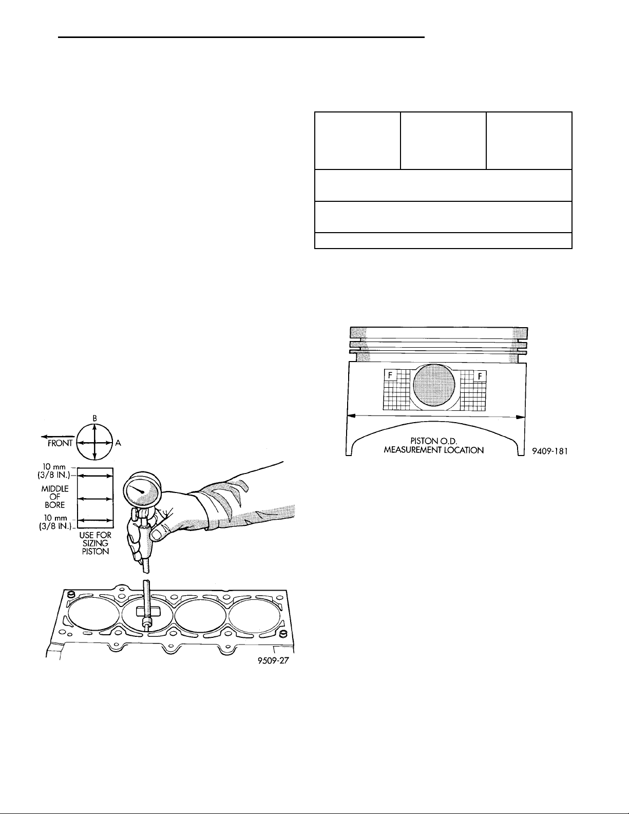
The cylinder walls should be checked for out-ofround and taper with Tool C-119 (Fig. 3). The cylinder bore out-of-round is 0.050 mm (.002 inch)
maximum and cylinder bore taper is 0.051 mm (0.002
inch) maximum. If the cylinder walls are badly
scuffed or scored, the cylinder block should be
rebored and honed, and new pistons and rings fitted.
Whatever type of boring equipment is used, boring
and honing operation should be closely coordinated
with the fitting of pistons and rings in order that
specified clearances may be maintained. Refer to
Honing Cylinder Bores outlined in the Standard Service Procedures for specification and
procedures.
Measure the cylinder bore at three levels in directions A and B (Fig. 3). Top measurement should be
10 mm (3/8 inch) down and bottom measurement
should be 10 mm (3/8 inch.) up from bottom of bore.
Refer to Cylinder Bore and Piston Specifications
Table.
Standard Bore Maximum
Out-of-Round
87.5 mm (3.445
in.)
0.051 mm
(0.002 in.)
Maximum
Taper
0.051 mm
(0.002 in.)
Standard Piston Size
87.463 - 87.481 mm (3.4434 - 3.4441 in.)
Piston to Bore Clearance
0.012 - 0.044 mm (0.0004 - 0.0017 in.)
Measurements Taken at Piston Size Location
and transverse to the engine crankshaft center line
shown in (Fig. 3). Refer to Cylinder Bore and Specifications Table. Correct piston to bore clearance must
be established in order to assure quiet and economical operation.
Fig. 3 Checking Cylinder Bore Size
SIZING PISTONS
Piston and cylinder wall must be clean and dry.
Piston diameter should be measured 90 degrees to
piston pin about 17.5 mm (11/16 inch) from the bottom of the skirt as shown in (Fig. 4). Cylinder bores
should be measured halfway down the cylinder bore
Fig. 4 Piston Measurements
Chrysler engines use pistons designed specifically
for each engine model. Clearance and sizing locations
vary with respect to engine model.
NOTE: Pistons and cylinder bores should be measured at normal room temperature, 21°C (70°F).
FITTING PISTON RINGS
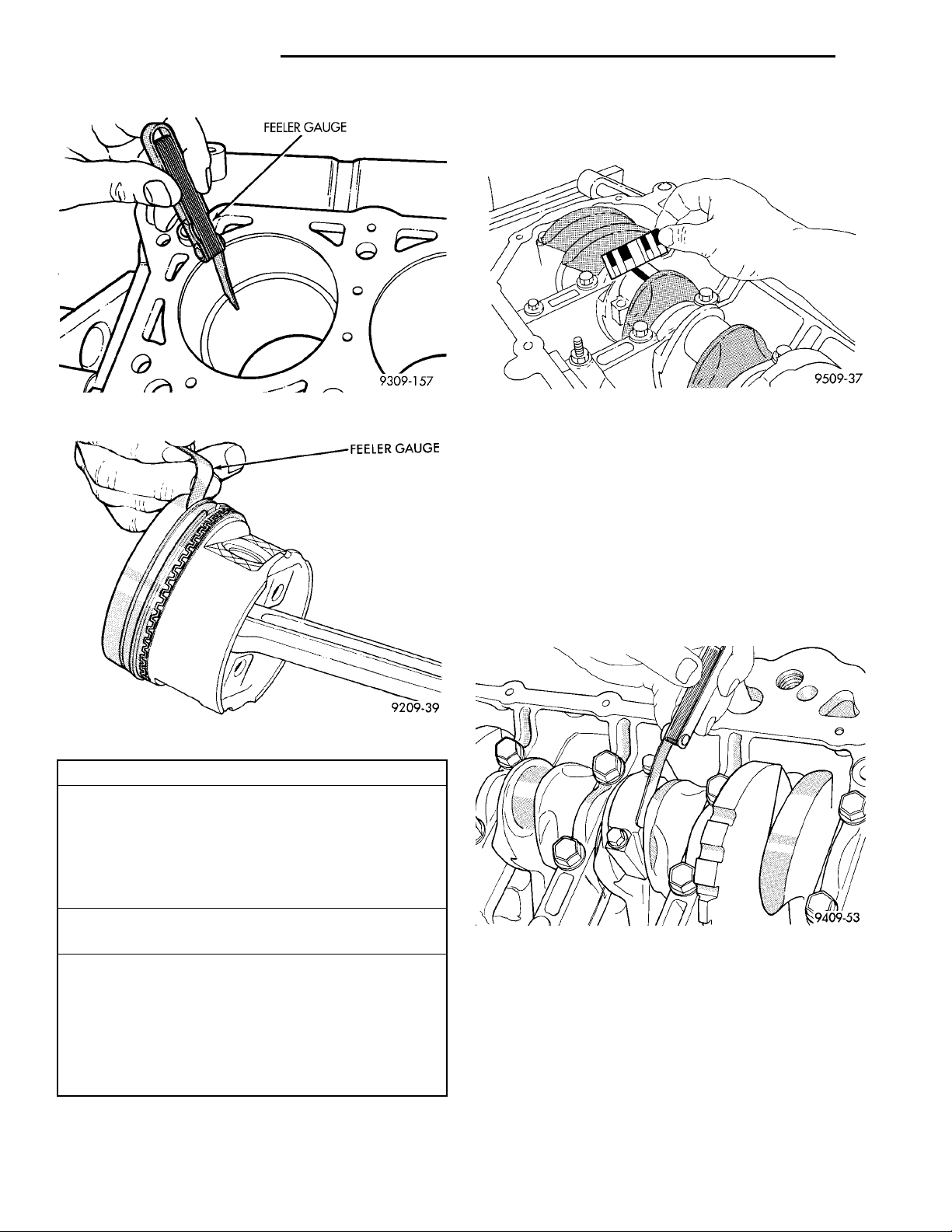
(1) Wipe cylinder bore clean. Insert ring and push
down with piston to ensure it is square in bore. The
ring gap measurement must be made with the ring
positioning at least 12 mm (0.50 inch) from bottom of
cylinder bore. Check gap with feeler gauge (Fig. 5).
Refer to specifications (Fig. 7).
(2) Check piston ring to groove side clearance (Fig.
6). Refer to specification (Fig. 7).
FITTING CONNECTING RODS
(1) Follow the procedure specified in the Standard
Service Procedures Section for Measuring Main Bearing Clearance and Connecting Rod Bearing Clearance (Fig. 8). Refer to specifications.
Page 16
FEELER GAUGE
FEELER GAUGE
9 - 16 2.0L SOHC ENGINE PL
SERVICE PROCEDURES (Continued)
CAUTION: Do not rotate crankshaft or the Plastigage may be smeared.
Fig. 5 Piston Ring Gap
Fig. 6 Piston Ring Side Clearance
Ring Position Ring Gap Wear Limit
Upper Ring 0.23 to 0.52 mm
(0.009 to 0.020 in.)
Intermediate
Ring
Oil Control
Ring
0.49 to 0.78 mm
(0.019 to 0.031 in.)
0.23 to 0.66 mm
(0.009 to 0.026 in.)
0.8 mm
(0.031 in.)
1.0 mm
(0.039 in.)
1.0 mm
(0.039 in.)
Fig. 8 Checking Connecting Rod Bearing Clearance
NOTE: The rod bearing bolts should not be reused.
(2) Before installing the NEW bolts the threads
should be oiled with clean engine oil.
(3) Install each bolt finger tight than alternately
torque each bolt to assemble the cap properly.
(4) Tighten the bolts to 27 N·m PLUS 1/4 turn (20
ft. lbs. PLUS 1/4 turn) Do not use a torque
wrench for last step.
(5) Using a feeler gauge, check connecting rod side
clearance (Fig. 9). Refer to connecting rod specifications (Fig. 10).
Ring Position Groove Clearance Maximum
Clearance
Upper Ring 0.025 to 0.065 mm
(0.0010 to 0.0026 in.)
Intermediate
Ring
0.025 to 0.065 mm
(0.0010 to 0.0026 in.)
0.10 mm
(0.004 in.)
0.10 mm
(0.004 in.)
OIL CONTROL RING - THREE PIECE. OIL RING
SIDE RAILS MUST BE FREE TO ROTATE AFTER
ASSEMBLY.
Fig. 7 Piston Ring Specifications
Fig. 9 Checking Connecting Rod Side Clearance
Page 17
PL 2.0L SOHC ENGINE 9 - 17
SERVICE PROCEDURES (Continued)
CONNECTING ROD BEARING OIL CLEARANCE
New Part: 0.026 to 0.059 mm
(0.001 to 0.0023 in.)
Wear Limit: 0.075 mm
(0.003 in.)
CONNECTING ROD SIDE CLEARANCE
New Part: 0.13 to 0.38 mm
(0.005 to 0.015 in.)
Wear Limit: 0.40 mm
(0.016 in.)
Fig. 10 Connecting Rod Specifications
FITTING CRANKSHAFT BEARINGS
Refer to Measuring Main Bearing Clearance in
Standard Service Procedures. Refer to (Fig. 11) for
specifications.
Crankshaft End-Play
New Part: 0.09 - 0.24 mm (0.0035 -
0.0094 in.)
Wear Limit: 0.37 mm (0.015 in.)
Main Bearing Clearance
New Part: .022 - .062 mm
(0.0008 - 0.0024 in.)
Connecting Rod Bearing Clearance
New Part: 0.026 - .059 mm
(0.001 - 0.0023 in.)
Wear Limit: 0.075 mm (0.003 in.)
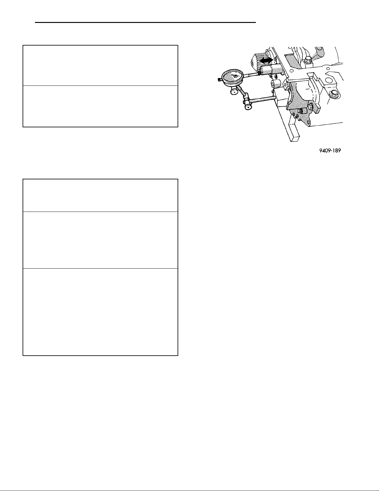
Fig. 12 Checking Crankshaft End Play— Dial
Indicator
FEELER GAGE METHOD
(1) Move crankshaft all the way to the rear of its
travel using a lever inserted between a main bearing
cap and a crankshaft cheek, using care not to damage any bearing surface. Do not loosen main bearing
cap.
(2) Use a feeler gauge between number three
thrust bearing and machined crankshaft surface to
determine end play.
REMOVAL AND INSTALLATION
Crankshaft Journal Sizes
Main Bearing Journal Diameter
Standard 52.000 6 0.008 mm
(2.0472 6 0.0003 in.)
1st Undersize 51.983 6 0.008 mm
(2.0466 6 0.0003 in.)
Connecting Rod Journal
Standard 48.000 6 0.008 mm
(1.8897 6 0.0003 in.)
1st Undersize 47.983 6 0.008 mm
(1.8891 6 0.0003 in.)
Fig. 11 Crankshaft Specifications
CRANKSHAFT END PLAY
DIAL INDICATOR METHOD
(1) Mount a dial indicator to front of engine, locat-
ing probe on nose of crankshaft (Fig. 12).
(2) Move crankshaft all the way to the rear of its
travel.
(3) Zero the dial indicator.
(4) Move crankshaft all the way to the front and
read the dial indicator. Refer to (Fig. 11) for specifications.
FRONT MOUNT
(1) Raise vehicle on hoist.
(2) Support the engine and transmission assembly
with a floor jack so it will not rotate.
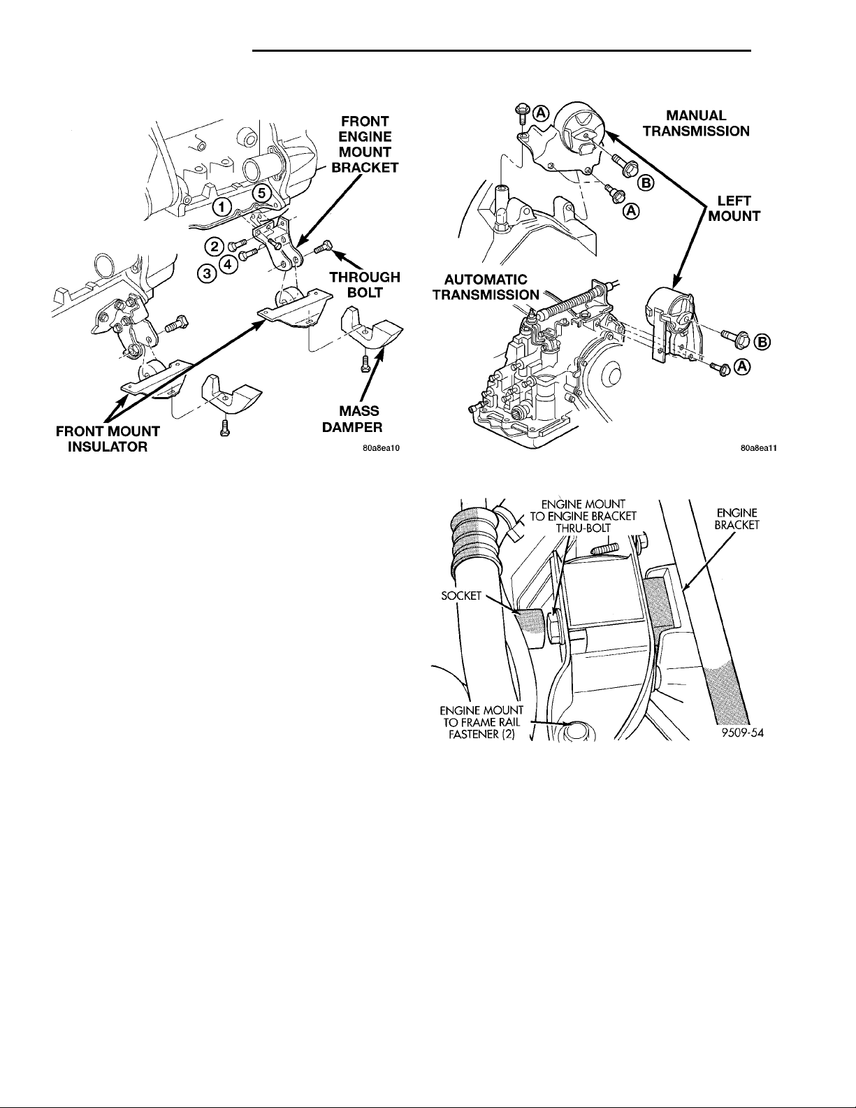
(3) Remove the front engine mount thru-bolt from
the insulator and engine mount bracket (Fig. 13).
(4) Remove the mass damper. Remove the front
mount nuts and remove insulator assembly.
(5) Remove the engine mount bracket, if necessary.
(6) Reverse removal procedure for installation and
tighten fasteners in this order.
a. If engine mount bracket was removed, tighten
bolt 1 to 3 N·m (20 in. lbs.) and bolts 2, 3 and 4 to
108 N·m (80 ft. lbs.) (Fig. 13).
b. If engine mount bracket was removed, tighten
bolts 5 and 1 to 54 N·m (40 ft. lbs.).
c. Tighten engine mount bracket to insulator
assembly thru-bolt to 54 N·m (40 ft. lbs.).
d. Tighten insulator assembly nuts to the lower
radiator crossmember torque to 54 N·m (40 ft. lbs.).
e. Install mass damper and tighten to 54 N·m (40
ft. lbs.)
Page 18
FRONT ENGINE MOUNTBRACKETTHROUGH BOLTMASS DAMPERFRONT MOUNT INSULATOR
9 - 18 2.0L SOHC ENGINE PL
REMOVAL AND INSTALLATION (Continued)
ENGINE MOUNT TO ENGINEBRACKET THRU-BOLT ENGINE BRACKETENGINE MOUNT TOFRAME RAIL FAS-TENER (2)SOCKET
Fig. 13 Engine Mounting—Front
LEFT MOUNT
(1) Raise vehicle on hoist and remove left front
wheel.
(2) Remove the Power Distribution Center (PDC)
on manual transaxle model, from battery tray mount
and lay aside.
(3) Support the transmission with a transmission
jack.
(4) Remove the thru-bolt access hole cover. Remove
the insulator thru-bolt from the mount (Fig. 14).
(5) Remove the transmission mount fasteners and
remove mount.
(6) Reverse removal procedure for installation.
Tighten fasteners in this order (Fig. 14):
A. 55 N·m (40 ft. lbs.)
B. 108 N·m (80 ft. lbs.)
RIGHT MOUNT
(1) Remove the purge duty solenoid from engine
mount bracket.
(2) Remove the right engine mount insulator vertical fasteners from frame rail (Fig. 15).
(3) Remove the load on the engine mounts by carefully supporting the engine and transmission assembly with a floor jack.
(4) Remove the thru-bolt access hole cover. Remove
the thru-bolt from the insulator assembly (Fig. 15).
Remove insulator.
(5) Reverse removal procedure for installation.
Tighten engine mount to rail fasteners to 54 N·m (40
ft. lbs.), then tighten engine mount to engine bracket
thru-bolt to 108 N·m (80 ft. lbs.).
Fig. 14 Engine Mounting—Left
Fig. 15 Engine Mounting—Right
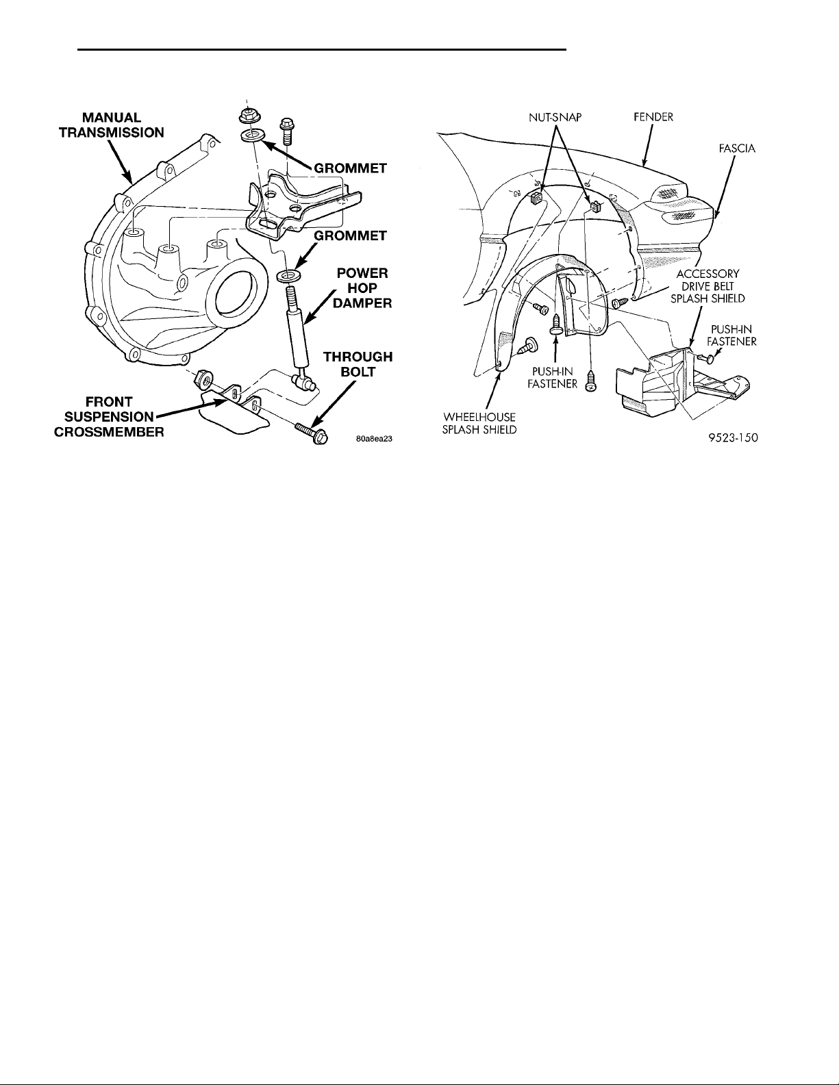
POWER HOP DAMPER
NOTE: Power hop damper is used on manual transmission vehicle only.
(1) Remove the thru-bolt and nut from the front
suspension crossmember (Fig. 16).
(2) Remove the damper nut and grommets.
Remove the damper.
(3) Remove the power hop damper bracket, if nec-
essary.
(4) Reverse removal procedure for installation.
Tighten all bolts and nuts to 54 N·m (40 ft. lbs.)
Page 19
MANUAL TRANSMISSIONGROMMETGROMMETPOWER HOP DAMPERTHROUGH BOLTFRONT SUSPENSIONCROSSMEMBER
NUT-SNAPPUSH-INFASTENERWHEELHOUSE SPLASHSHIELD FENDER FASCIAACCESSORY DRIVEBELT SPLASH SHIELDPUSH-IN FAS-TENER
PL 2.0L SOHC ENGINE 9 - 19
REMOVAL AND INSTALLATION (Continued)
Fig. 16 Power Hop Damper
ENGINE ASSEMBLY
REMOVAL
(1) Perform fuel pressure release procedure. Refer
to Group 14, Fuel System for procedure. Remove fuel
line to fuel rail.
(2) Disconnect and remove battery and tray. Set
Powertrain Control Module (PCM) aside.
(3) Drain cooling system. Refer to Group 7, Cooling
System for procedure.
(4) Remove upper radiator hose, radiator and fan
module. Refer to Group 7, Cooling System for procedure.
(5) Remove lower radiator hose.
(6) Disconnect automatic transmission cooler lines
and plug. If equipped.
(7) Disconnect clutch cable (Manual) and transmission shift linkage.
(8) Disconnect throttle body linkage.
(9) Disconnect engine wiring harness.
(10) Disconnect heater hoses.
(11) Discharge Air Conditioning System. Refer to
Group 24, Air Conditioning for procedure.
(12) Hoist vehicle and remove right inner splash
shield (Fig. 17).
(13) Remove accessory drive belts. Refer to Group
7, Cooling System for procedure.
(14) Remove axle shafts. Refer to Group 2, Suspension and Driveshafts for procedure.
(15) Disconnect exhaust pipe from manifold.
(16) Remove front engine mount.
(17) Manual transmission: Remove power hop
damper.
Fig. 17 Right Inner Splash Shield
(18) Lower vehicle. Remove air cleaner assembly.
(19) Remove power steering pump and reservoir,
Set them aside.
(20) Remove A/C compressor.
(21) Remove ground straps to body.
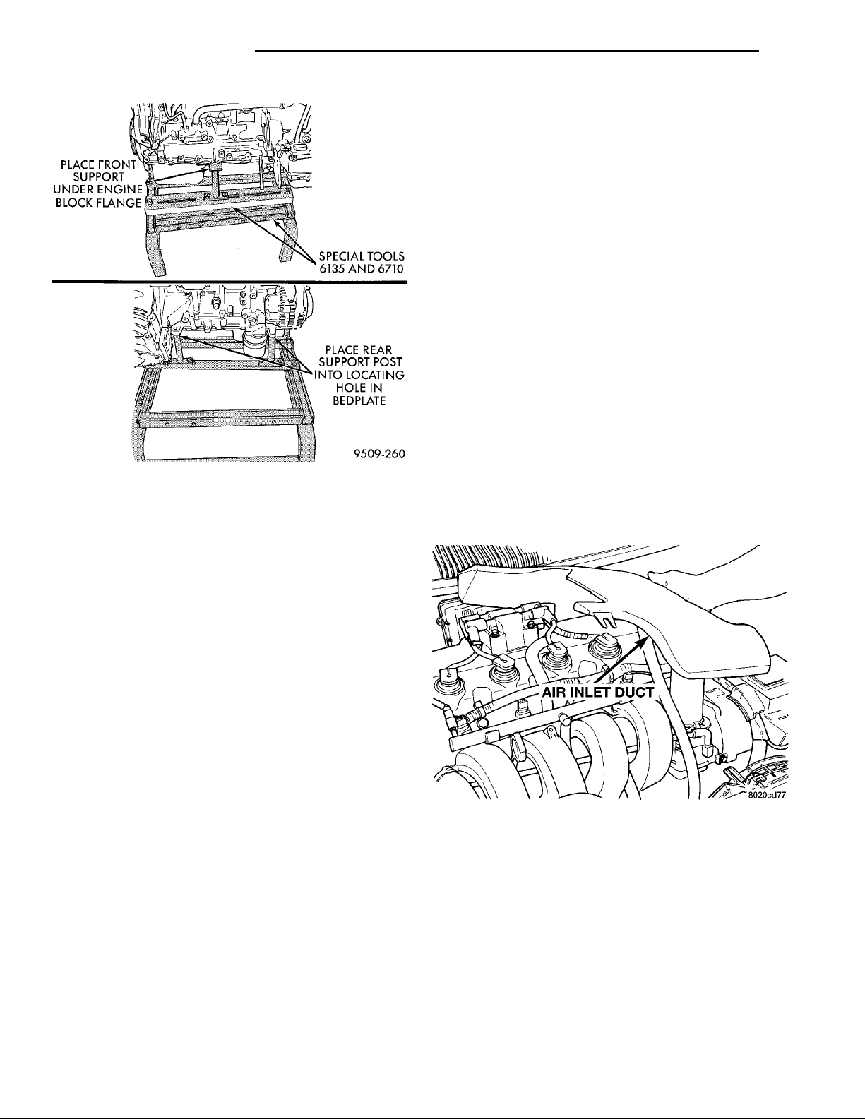
(22) Raise vehicle enough to allow engine dolly
and cradle Special Tools 6135 and 6710 to be
installed under vehicle.
(23) Loosen engine support posts to allow movement for positioning onto engine locating holes and
flange on the engine bedplate. Lower vehicle and
position cradle until the engine is resting on support
posts (Fig. 18). Tighten mounts to cradle frame. This
will keep support posts from moving when removing
or installing engine and transmission.
(24) Install safety straps around the engine to cradle tighten; straps and lock them into position.
(25) Raise vehicle enough to see if straps are tight
enough to hold cradle assembly to engine.
(26) Lower vehicle so weight of the engine and
transmission ONLY is on the cradle assembly.
(27) Remove engine and transmission mount thrubolts.
(28) Raise vehicle slowly. It may be necessary to
move the engine/transmission assembly with the cradle to allow for removal around body flanges.
INSTALLATION
(1) Position engine and transmission assembly
under vehicle and slowly lower the vehicle over the
engine and transmission.
(2) Align engine and transmission mounts to
attaching points. Install mounting bolts at the right
Page 20
PLACE FRONT SUP-PORT UNDERENGINE BLOCKFLANGE SPECIAL TOOLS6135 AND 6710PLACE REAR SUP-PORT POST INTOLOCATING HOLE INBEDPLATE
9 - 20 2.0L SOHC ENGINE PL
REMOVAL AND INSTALLATION (Continued)
(15) Connect fuel line and heater hoses.
(16) Install ground straps. Connect engine and
throttle body connections and harnesses. Refer to
Group 8, Electrical for procedure.
(17) Connect throttle body linkage. Refer to Group
AIR INLET DUCT
14, Fuel System for procedure.
(18) Install radiator and shroud assembly. Install
radiator hoses. Fill cooling system. Refer to Group 7,
Cooling System for filling procedure.
(19) Install battery tray and battery. Set Powertrain Control Module (PCM) into place.
(20) Install air cleaner and hoses.
(21) Install oil filter. Fill engine crankcase with
proper oil to correct level.
(22) Start engine and run until operating temperature is reached.
(23) Adjust transmission linkage, if necessary.
CYLINDER HEAD COVER
Fig. 18 Positioning Engine Cradle Support Post
Mounts
engine and left transmission mounts. Refer to procedures outlined in this section.
(3) Remove safety straps from engine and transmission assembly. Slowly raise vehicle enough to
remove the engine dolly and cradle.
(4) Install axle shafts. Refer to Group 2, Suspension and Driveshafts for procedure.
(5) Install transmission and engine braces and
splash shields.
(6) Connect exhaust system to manifold. Refer to
Group 11, Exhaust System and Intake Manifold for
procedure and torque specifications.
(7) Install power steering pump and reservoir.
Refer to Group 7, Cooling System Accessory Drive
Section for belt tension adjustment.
(8) Install A/C compressor and hoses. Refer to
Group 24, Heater and Air Conditioning for procedure.
(9) Install accessory drive belts. Refer to Group 7,
Cooling System Accessory Drive Section for belt tension adjustment.
(10) Install front engine mount. Refer to this section for procedure.
(11) Manual transmission: Install power hop
damper.
(12) Install inner splash shield. Install wheels and
tires.
(13) Manual Transmission: Connect clutch cable
and linkages. Refer to Group 6, Manual Transaxle
Clutch.
(14) Automatic Transmission: Connect shifter
and kickdown linkage. Refer to Group 21, Transaxle
for procedures.
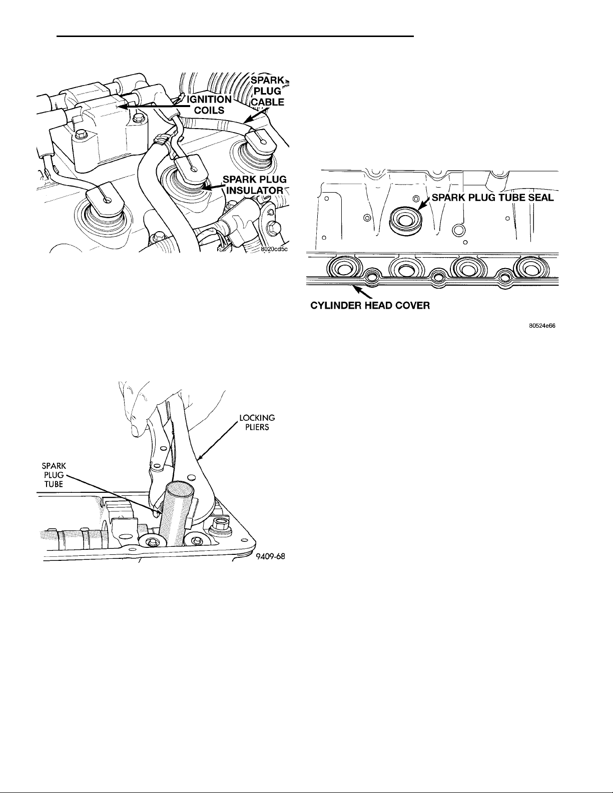
REMOVAL
(1) Remove air cleaner inlet duct (Fig. 19)
(2) Remove ignition coil pack (Fig. 20).
(3) Remove the cylinder head cover bolts.
(4) Remove cylinder head cover from cylinder
head.
Fig. 19 Inlet Duct Removal
INSTALLATION
Before installation, clean cylinder head and cover
mating surfaces. Make certain the cylinder head
cover mating surface is flat.
(1) Install new valve cover gasket.
CAUTION: Do not allow oil or solvents to contact
the timing belt as they can deteriorate the rubber
and cause tooth skipping.
(2) Install cover assembly to head and tighten fasteners to 12 N·m (105 in. lbs.).
Page 21
IGNITIONCOILSSPARK PLUG CABLESPARK PLUGINSULATOR
LOCKINGPLIERSSPARK PLUGTUBE
SPARK PLUG TUBE SEALCYLINDER HEAD COVER
PL 2.0L SOHC ENGINE 9 - 21
REMOVAL AND INSTALLATION (Continued)
SPARK PLUG TUBE SEALS
The spark plug tube seals are located in the cylinder head cover (Fig. 22). These seals are pressed into
the cylinder head cover to seal the end of the spark
plug tubes. If these seals show signs of hardness
and/or cracking they should be replaced.
Fig. 20 Ingition Coil Pack
(3) Install ignition coil pack. Tighten fasteners to
23 N·m (200 in. lbs.).
SPARK PLUG TUBE
(1) Remove valve cover. Refer to procedure out-
lined in this section.
(2) Using locking pliers remove the tube from the
cylinder head (Fig. 21). Discard old tube.
Fig. 21 Servicing Spark Plug Tubes
(3) Clean area around spark plug with MOPAR
parts cleaner or equivalent.
(4) Apply Loctite sealer 271 or Mopar Stud and
Bearing Mount or equivalent to a new tube approximately 1 mm from the end ina3mmwide area.
(5) Install sealer end of tube into the cylinder
head. Then carefully install the tube using a hardwood block and mallet until the tube is seated into
the bottom of the bore.
(6) Install valve cover. Refer to procedure outlined
in this section.
Fig. 22 Spark Plug Tube Seals
CAMSHAFT
NOTE: TO REMOVE CAMSHAFT CYLINDER HEAD
MUST BE REMOVED.
REMOVAL
(1) Refer to Timing Belt Removal for timing belt
and camshaft sprocket removal and installation.
(2) Remove the cylinder head cover.
(3) Mark rocker arm shaft assemblies for installa-
tion.
(4) Remove rocker arm shaft bolts. Refer to proce-
dure outlined in this section.
(5) Remove the timing belt and camshaft sprocket.
Refer to timing belt service outlined in this section.
(6) Remove cylinder head. Refer to procedure out-
lined in this section.
(7) Remove camshaft sensor and remove camshaft
from the rear of the head.
Page 22
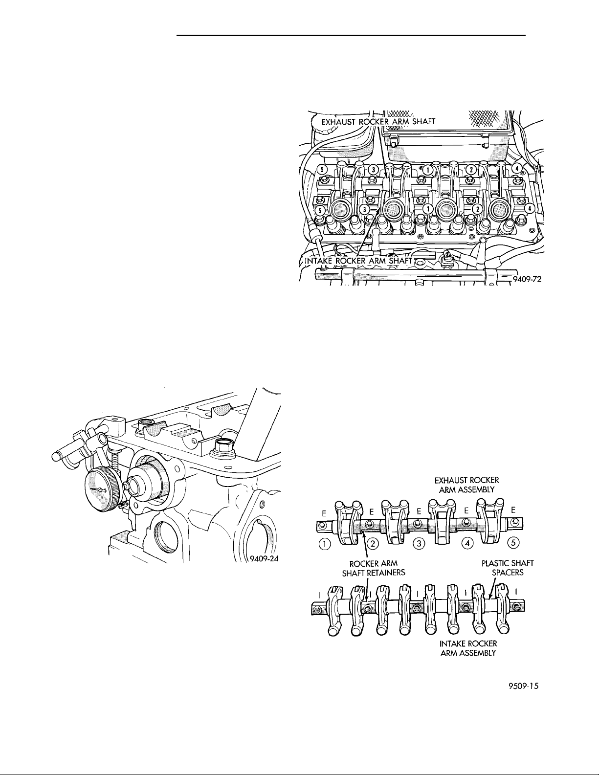
EXHAUST ROCKER ARM SHAFT
INTAKE ROCKER ARM SHAFT
EXHAUST ROCKER ARMASSEMBLYPLASTIC SHAFTSPACERSINTAKE ROCKER ARMASSEMBLYROCKER ARMSHAFT RETAINERS
9 - 22 2.0L SOHC ENGINE PL
REMOVAL AND INSTALLATION (Continued)
NOTE: Check oil feed holes for blockage.
Inspect cylinder head journals for wear, Refer to
Cylinder Head, Inspect and Cleaning.
Check camshaft bearing journals for scratches
and worn areas. If light scratches are present, they
may be removed with 400 grit sand paper. If deep
scratches are present, replace the camshaft and
check the cylinder head for damage. Replace the
cylinder head if worn or damaged. Check the lobes
for pitting and wear. If the lobes show signs of
wear, check the corresponding rocker arm roller for
wear or damage. Replace rocker arm/hydraulic lash
adjuster if worn or damaged. If lobes show signs of
pitting on the nose, flank or base circle; replace the
camshaft.
CAMSHAFT END PLAY
(1) Oil camshaft journals and install camshaft
without rocker arm assemblies. Install cam sensor
and tighten screws to specified torque.
(2) Using a suitable tool, move camshaft as far
rearward as it will go.
(3) Zero dial indicator (Fig. 23).
(4) Move camshaft as far forward as it will go.
(5) End play travel: 0.13 - 0.33 mm (0.005 - 0.013
in.).
(6) Install rocker arm assemblies in correct order
as removed. Tighten the rocker arm assemblies in
sequence shown in (Fig. 24) to 23 N·m (200 in. lbs.).
Fig. 24 Rocker Arm Shaft Tightening Sequence
ROCKER ARM/HYDRAULIC LASH ADJUSTER
REMOVAL
(1) Remove valve cover using procedure outlined in
this section.
(2) Identify the rocker arm shaft assemblies before
removal.
(3) Loosen the attaching fasteners. Remove rocker
arm shaft assemblies from cylinder head.
(4) Identify the rocker arms spacers and retainers
for reassembly. Disassemble the rocker arm assemblies by removing the attaching bolts from the shaft
(Fig. 25).
Fig. 23 Camshaft End Play
INSTALLATION
(1) Lubricate camshaft journals. Install camshaft
into the cylinder head carefully.
(2) Install cam sensor and tighten fasteners to 9.5
N·m (85 in. lbs.).
(3) Install camshaft seal. Camshaft must be
installed before the camshaft seal is installed. Refer
to procedure outlined in this section.
(4) Install camshaft sprocket and tighten to 115
N·m (85 ft. lbs.).
(5) Install timing belt. (Refer to procedure outlined
in this section).
Fig. 25 Rocker Arm Shaft Assemblies
Page 23
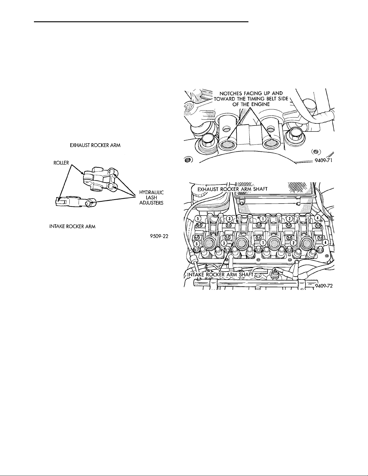
EXHAUST ROCKER ARM HYDRAULIC LASHADJUSTERSINTAKE ROCKER ARMROLLER
INTAKE ROCKER ARM SHAFT
NOTCHES FACING UP ANDTOWARD THE TIMING BELTSIDE OF THE ENGINE
EXHAUST ROCKER ARM SHAFT
PL 2.0L SOHC ENGINE 9 - 23
REMOVAL AND INSTALLATION (Continued)
(5) Slide the rocker arms and spacers off the shaft.
Keep the spacers and rocker arms in the same location for reassembly.
NOTE: Inspect the rocker arm for scoring, wear on
the roller or damage to the rocker arm (Fig. 26)
Replace if necessary. Check the location where the
rocker arms mount to the shafts for wear or damage. Replace if damaged or worn. The rocker arm
shaft is hollow and is used as a lubrication oil duct.
Check oil holes for clogging with small wire, clean
as required. Lubricate the rocker arms and spacers.
Install onto shafts in their original position (Fig. 25).
angle. To avoid damaging the spark plug tubes, do
not attempt rotating the spacers by forcing down
the shaft assembly.
(3) Tighten bolts to 23 N·m (200 in. lbs.) in
sequence shown in (Fig. 28).
Fig. 27 Rocker Arm Shaft Notches
Fig. 26 Rocker Arm Assemblies
INSTALLATION
CAUTION: Set crankshaft to 3 notches before TDC
before installing rocker arm shafts. Refer to Timing
Belt System and Camshaft Seal Service of this section for procedure.
(1) Install rocker arm/hydraulic lash adjuster
assembly making sure that adjusters are at least
partially full of oil. This is indicated by little or no
plunger travel when the lash adjuster is depressed. If
there is excessive plunger travel. Place the rocker
arm assembly into clean engine oil and pump the
plunger until the lash adjuster travel is taken up. If
travel is not reduced, replace the assembly. Hydraulic
lash adjuster and rocker arm are serviced as an
assembly.
(2) Install rocker arm and shaft assemblies with
NOTCH in the rocker arm shafts pointing up and
toward the timing belt side of the engine (Fig. 27).
Install the retainers in their original positions on the
exhaust and intake shafts (Fig. 25).
CAUTION: When installing the intake rocker arm
shaft assembly be sure that the plastic spacers do
not interfere with the spark plug tubes. If the spacers do interfere rotate until they are at the proper
Fig. 28 Rocker Arm Shaft Tightening Sequence
HYDRAULIC LASH ADJUSTER NOISE
A tappet-like noise may be produced from several
items. Refer to Lash Adjuster Noise - Diagnosis in
Standard Service Procedures, outlined in this Group.
Lash adjusters are replaced with the rocker
arm as an assembly.
VALVE SEALS AND SPRINGS IN VEHICLE
REMOVAL
(1) Remove rocker arm shafts assemblies as previously outlined in this section.
(2) Rotate crankshaft until piston is at TDC on
compression.
(3) With air hose attached to adapter tool installed
in spark plug hole, apply 90-120 psi air pressure.
(4) Using Special Tool MD-998772A with adapter
6779 (Fig. 29) compress valve springs and remove
valve locks.
(5) Remove valve spring.
Page 24
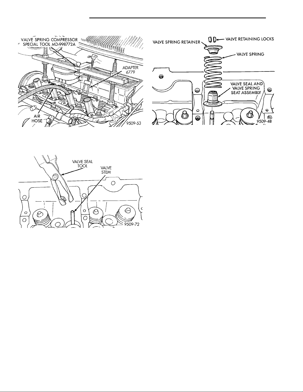
VALVE SPRING COMPRES-SOR SPECIAL TOOLMD-998772A ADAPTER6779AIR HOSE
VALVE SEAL TOOL VALVE STEM
VALVE RETAINING LOCKSVALVESPRINGVALVE SEAL ANDVALVE SPRING SEATASSEMBLYVALVE SPRINGRETAINER
9 - 24 2.0L SOHC ENGINE PL
REMOVAL AND INSTALLATION (Continued)
Fig. 29 Removing and Installing Valve Spring
(6) Remove valve stem seal by using a valve stem
seal tool (Fig. 30).
Fig. 30 Valve Stem Oil Seal Tool
INSTALLATION
(1) Install valve seal/valve spring seat assembly
as outlined in the Valve Installation procedure in this
section.
(2) Using Special Tool MD-998772A compress valve
springs only enough to install locks. Correct alignment of tool is necessary to avoid nicking valve stems
(air pressure required), piston at TDC.
(3) Install rocker arm shaft assemblies as previously outlined in this section.
(4) Install valve cover as previously outlined in
this section.
CYLINDER HEAD
REMOVAL
(1) Perform fuel system pressure release procedure
before attempting any repairs. Refer to Group 14,
Fuel System
(2) Disconnect negative battery cable. Drain cooling system. Refer to Group 7, Cooling System.
Fig. 31 Valve Spring Assembly
(3) Remove air cleaner inlet duct and air cleaner
(Fig. 32), disconnect all vacuum lines, electrical wiring and fuel lines from throttle body.
(4) Remove throttle linkage.
(5) Remove accessory drive belts. Refer to Group 7,
Cooling System for procedure.
(6) Remove power brake vacuum hose from intake
manifold.
(7) Raise vehicle and remove exhaust pipe from
manifold.
(8) Remove power steering pump assembly and set
aside.
(9) Disconnect coil pack wiring connector and
remove coil pack and bracket from engine.
(10) Remove cylinder head cover.
(11) Remove cam sensor and fuel injectors wiring
connectors.
(12) Remove intake manifold SOHC ONLY .
Removal procedure outline in Group 11.
(13) Remove timing belt and camshaft sprocket.
Refer to procedure outlined in this section.
(14) Remove rocker arm shaft assemblies.
(15) Remove cylinder head bolts.
NOTE: Inspect camshaft bearing journals for scoring. Cylinder head must be flat within 0.1 mm (0.004
inch) (Fig. 33).
INSTALLATION
(1) Before installing the bolts the threads should
be oiled with engine oil. The 4 short bolts 110 mm
(4.330 in.) are to be installed in positions 7, 8, 9, and
10 (Fig. 34).
(2) Tighten the cylinder head bolts in the sequence
shown in (Fig. 34). Using the 4 step torque method,
tighten according to the following values:
• First All to 34 N·m (25 ft. lbs.)
• Second All to 68 N·m (50 ft. lbs.)
• Third All to 68 N·m (50 ft. lbs.)
Page 25
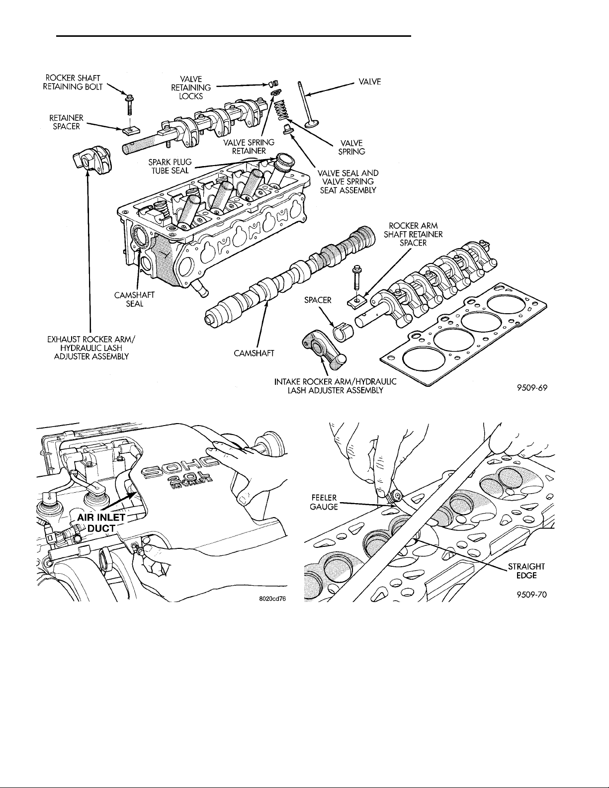
ROCKER SHAFT RETAINING
AIR INLET DUCT
BOLT
VALVE RETAINING LOCKS VALVEVALVE SPRINGVALVE SEAL AND VALVESPRING SEAT ASSEMBLYROCKER ARM SHAFTRETAINER SPACERINTAKE ROCKER ARM/HYDRAULICLASH ADJUSTER ASSEMBLYCAMSHAFT SPACEREXHAUST ROCKER ARM/HY-DRAULIC LASH ADJUSTERASSEMBLYCAMSHAFT SEALSPARK PLUG TUBESEAL VALVE SPRING RETAINERRETAINER SPACER
FEELERGAUGE STRAIGHTEDGE
PL 2.0L SOHC ENGINE 9 - 25
REMOVAL AND INSTALLATION (Continued)
Cylinder Head and Valve Assembly
Fig. 32 Air Cleaner Inlet Duct
• Fourth Turn an additional 1/4 Turn, Do not use
a torque wrench for this step.
For the rest of installation, reverse removal proce-
dure.
Fig. 33 Checking Cylinder Head Flatness
TIMING BELT COVER
REMOVAL
(1) Remove accessory drive belts. Refer to Group 7,
Cooling System for procedure outlined in that section.
(2) Raise vehicle on a hoist and remove right inner
splash shield (Fig. 35).
(3) Remove crankshaft vibration damper. Refer to
procedure outlined in this section for removal.
Page 26
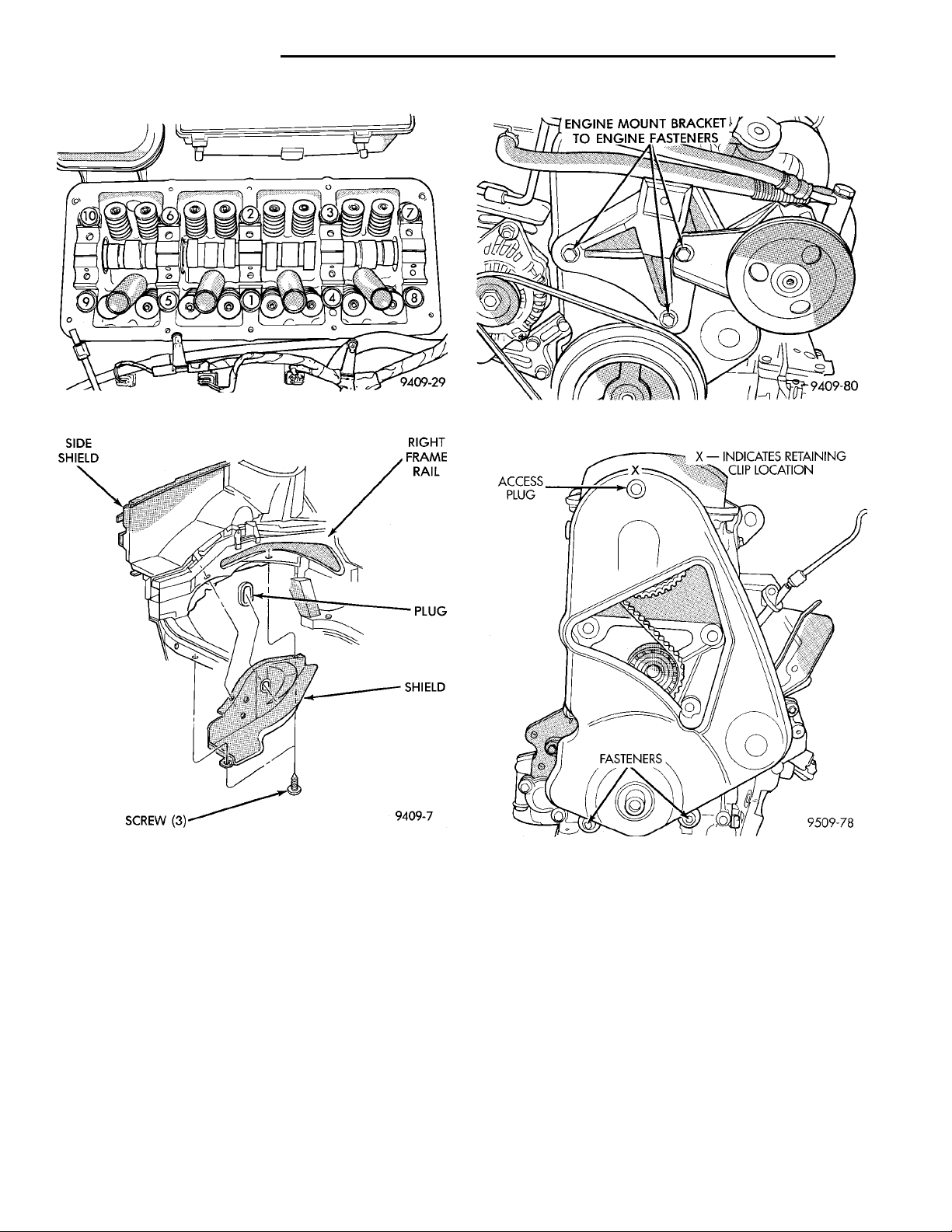
SIDESHIELD RIGHT FRAMERAILPLUGSHIELDSCREW(3)
ENGINE MOUNT BRACKET TOENGINE FASTENERS
INDICATES RETAININGCLIP LOCATIONFASTENERSACCESSPLUG
9 - 26 2.0L SOHC ENGINE PL
REMOVAL AND INSTALLATION (Continued)
Fig. 34 Cylinder Head Tightening Sequence
Fig. 35 Right Inner Splash Shield
(4) Lower vehicle and place a jack under engine.
(5) Remove right engine mount. Refer to procedure
outlined in this section.
(6) Remove right engine mount bracket (Fig. 36).
(7) Remove front timing belt cover (Fig. 37).
INSTALLATION
(1) Install front timing cover.
(2) Install engine mount bracket.
Fig. 36 Right Engine Mount Bracket
Fig. 37 Timing Belt Cover
(3) Install Right engine mount. Refer to procedure
outlined in this section for installation.
(4) Remove jack from under engine.
(5) Install crankshaft vibration damper Refer to
procedure outlined in this section for installation.
(6) Install accessory drive belts. Refer to Group 7,
Cooling System Accessory Drive section for procedure.
(7) Raise vehicle on hoist and install right inner
splash shield.
Page 27
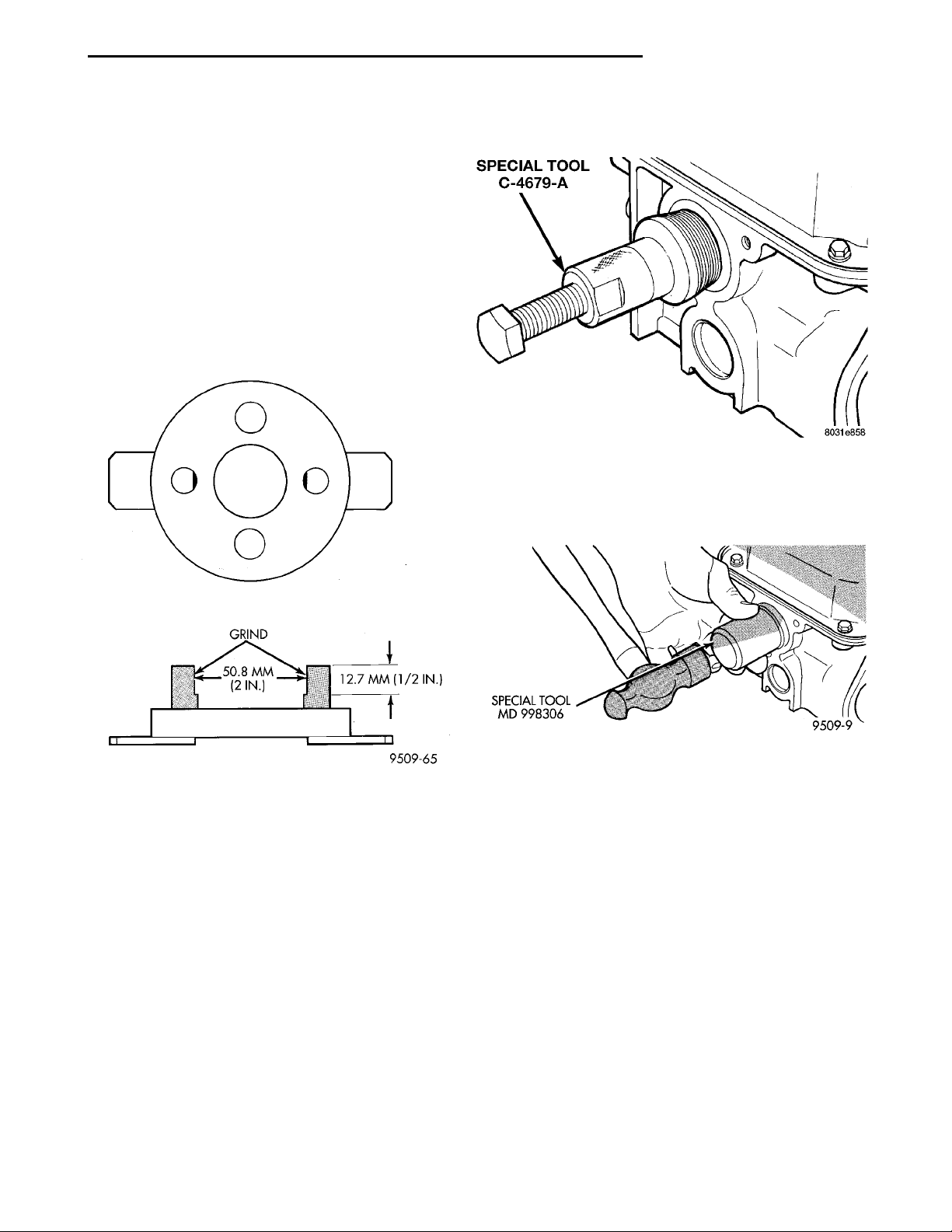
GRIND12.7 MM (1/2 IN.)50.8 MM (2 IN.)
PL 2.0L SOHC ENGINE 9 - 27
SPECIAL TOOLC-4679–A
REMOVAL AND INSTALLATION (Continued)
(4) Shaft seal lip surface must be free of varnish,
CAMSHAFT OIL SEAL
REMOVAL
CAUTION: Do Not Rotate the camshaft or crankshaft when timing belt is removed damage to the
engine may occur.
(1) Remove timing belt cover and belt. Removal
procedure is outlined in this section. Remove camshaft sprocket bolt, with the Modified Special Tool
C-4687-1 as shown in (Fig. 38).
(2) Hold camshaft sprocket with modified tool
while removing bolt. Remove sprocket from camshaft.
SPECIAL TOOL MD998306
dirt or nicks. Polish with 400 grit paper if necessary.
Fig. 39 Removing Camshaft Oil Seal
INSTALLATION
(1) Install camshaft seal flush with cylinder head
using Special Tool MD 998306 (Fig. 40).
Fig. 38 Modification to Special Tool
(3) Remove camshaft seal using Special Tool
C-4679–A (Fig. 39).
CAUTION: Do not nick shaft seal surface or seal
bore.
Fig. 40 Installing Camshaft Seal
(2) Install camshaft sprocket retaining bolt. Hold
camshaft sprocket with Special Tool C-4687-1 (Fig.
38) and tighten bolt to 115 N·m (85 ft. lbs.).
Page 28
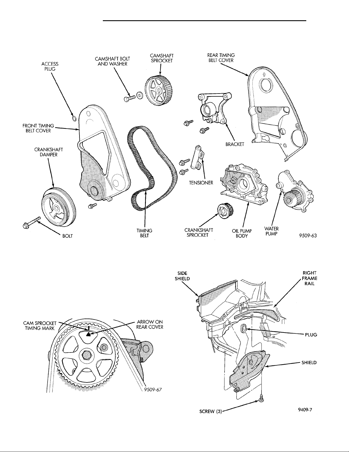
CAM SPROCKETTIMING MARK ARROW ONREAR COVER
ACCESS PLUG CAMSHAFT BOLT ANDWASHER CAMSHAFTSPROCKET REAR TIMING BELT COVERBRACKET WATER PUMPOIL PUMP BODYCRANKSHAFTSPROCKETTIMING BELT TENSIONERBOLTCRANKSHAFTDAMPERFRONT TIMING BELTCOVER
SIDESHIELD RIGHT FRAMERAILPLUGSHIELDSCREW(3)
9 - 28 2.0L SOHC ENGINE PL
REMOVAL AND INSTALLATION (Continued)
TIMING BELT SYSTEM
Fig. 41 Timing Belt System
CHECKING BELT TIMING—COVER INSTALLED
• Remove number one spark plug.
• Using a dial indicator, set number one cylinder
to TDC on the compression stroke.
• Remove the access plug from the outer timing
belt cover (Fig. 41).
• Check the timing mark on the camshaft
sprocket, it should align with the arrow on the rear
belt cover (Fig. 42).
Fig. 42 Camshaft Timing Marks
REMOVAL—TIMING BELT
(1) Remove accessory drive belts. Refer to Group 7,
Cooling System for procedure outlined in that section.
(2) Raise vehicle on a hoist and remove right inner
splash shield (Fig. 43).
Fig. 43 Right Inner Splash Shield
Page 29
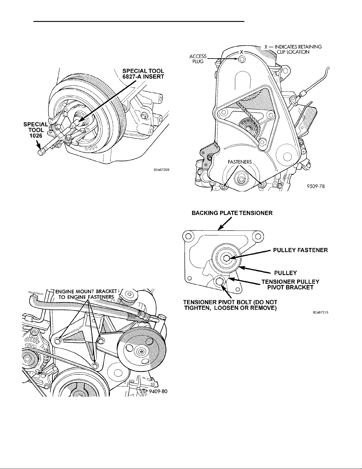
PL 2.0L SOHC ENGINE 9 - 29
REMOVAL AND INSTALLATION (Continued)
(3) Remove crankshaft damper bolt. Remove
damper using the large side of Special Tool 1026 and
insert 6827-A (Fig. 44).
BACKING PLATE TEN-SIONERPULLEY FASTENERPULLEYTENSIONER PULLEY PIVOTBRACKETTENSIONER PIVOT BOLT(DO NOT TIGHTEN, LOOSENOR REMOVE)
Fig. 44 Crankshaft Damper—Removal
(4) Lower vehicle and place a jack under engine.
(5) Remove right engine mount. Refer to procedure
outlined in this section.
(6) Remove right engine mount bracket (Fig. 45).
(7) Remove front timing belt cover (Fig. 46).
Fig. 46 Timing Belt Cover
CAUTION: Align camshaft and crankshaft timing
marks before removing the timing belt.
(8) Loosen timing belt tensioner fasteners (Fig. 48)
ENGINE MOUNT BRACKET TOENGINE FASTENERS
and remove timing belt and tensioner.
CAUTION: Do not loosen, tighten, or remove the
tensioner pivot bolt (Fig. 47).
Fig. 45 Right Engine Mount Bracket
Fig. 47 Tensioner Pulley Assembly
CAMSHAFT AND CRANKSHAFT TIMING PROCEDURE AND BELT INSTALLATION —SOHC ENGINE
(1) When tensioner is removed from the engine it
is necessary to compress the plunger into the tensioner body.
(2) Place the tensioner into a vise equipped with
soft jaws and slowly compress the plunger (Fig. 49).
CAUTION: Index the tensioner in the vise the same
way it is installed on the engine. This is to ensure
proper pin orientation when tensioner is installed
on the engine.
(3) When plunger is compressed into the tensioner
body install a 1.9 mm (5/64) allen wrench or pin
Page 30
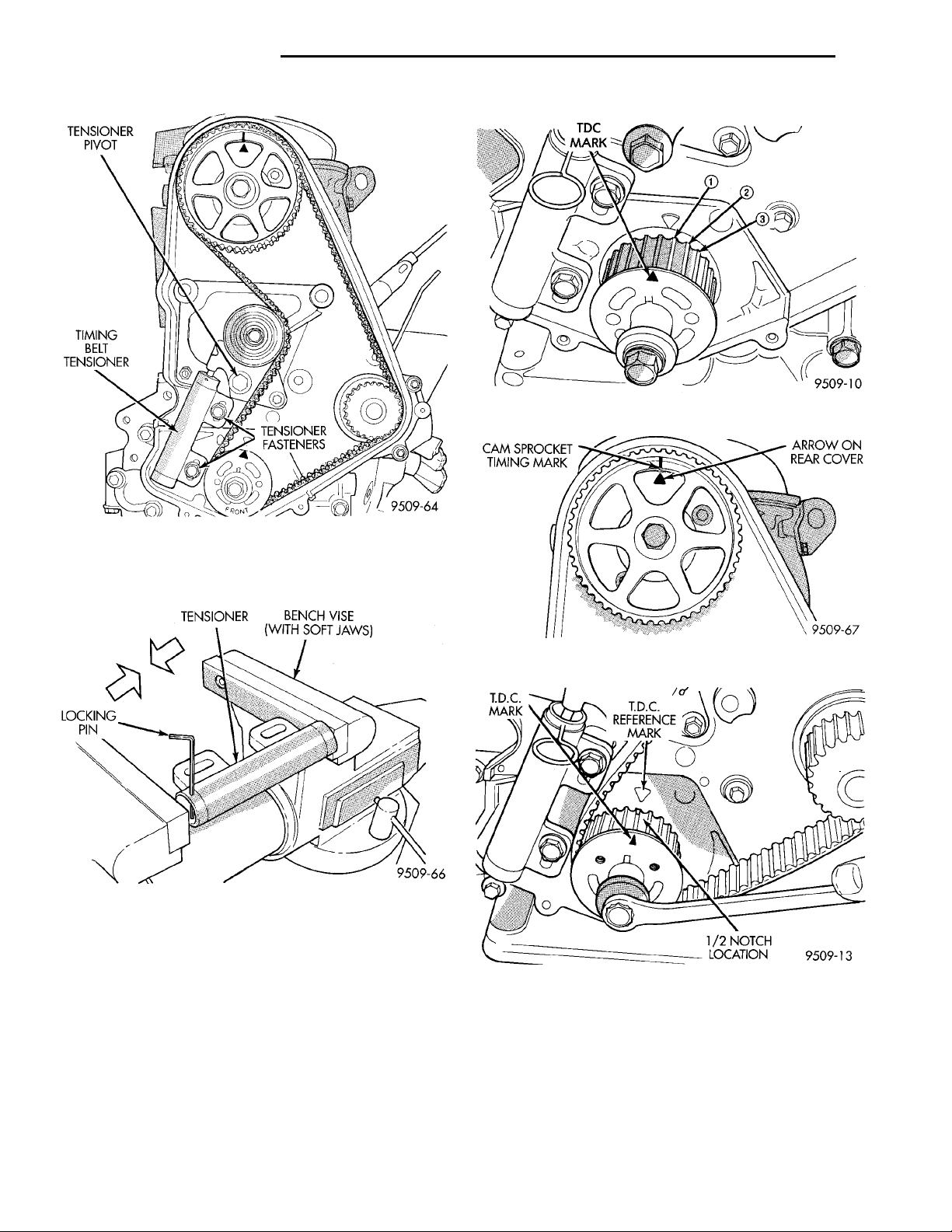
TENSIONERPIVOTTIMING BELT TEN-SIONER TENSIONERFASTENERS
CAM SPROCKETTIMING MARK ARROW ONREAR COVER
T.D.C.MARK T.D.C. REFER-ENCE MARK 1/2 NOTCH LOCATION
TDCMARK
9 - 30 2.0L SOHC ENGINE PL
TENSIONER BENCH VISE (WITH SOFTJAWS)LOCKING PIN
REMOVAL AND INSTALLATION (Continued)
Fig. 50 Crankshaft Sprocket Timing
Fig. 48 Remove Timing Belt
through the body and plunger to retain plunger in
place until tensioner is installed.
Fig. 49 Compressing Timing Belt Tensioner
(4) Set crankshaft sprocket to TDC by aligning the
sprocket with the arrow on the oil pump housing,
then back off to 3 notches before TDC (Fig. 50).
(5) Set camshaft to TDC by aligning mark on
sprocket with the arrow on the rear of timing belt
cover (Fig. 51).
(6) Move crankshaft to 1/2 mark before TDC (Fig.
52) for belt installation.
(7) Install timing belt. Starting at the crankshaft,
go around the water pump sprocket and then around
the camshaft sprocket.
Fig. 51 Camshaft Timing Mark
Fig. 52 Adjusting Crankshaft Sprocket for Timing
Belt Installation
(8) Move crankshaft sprocket to TDC to take up
belt slack. Install tensioner to block but do not
tighten fasteners.
(9) Using a torque wrench on the tensioner pulley
apply 28 N·m (250 in. lbs.) of torque (Fig. 53).
(10) With torque being applied to the tensioner
pulley move the tensioner up against the tensioner
Page 31
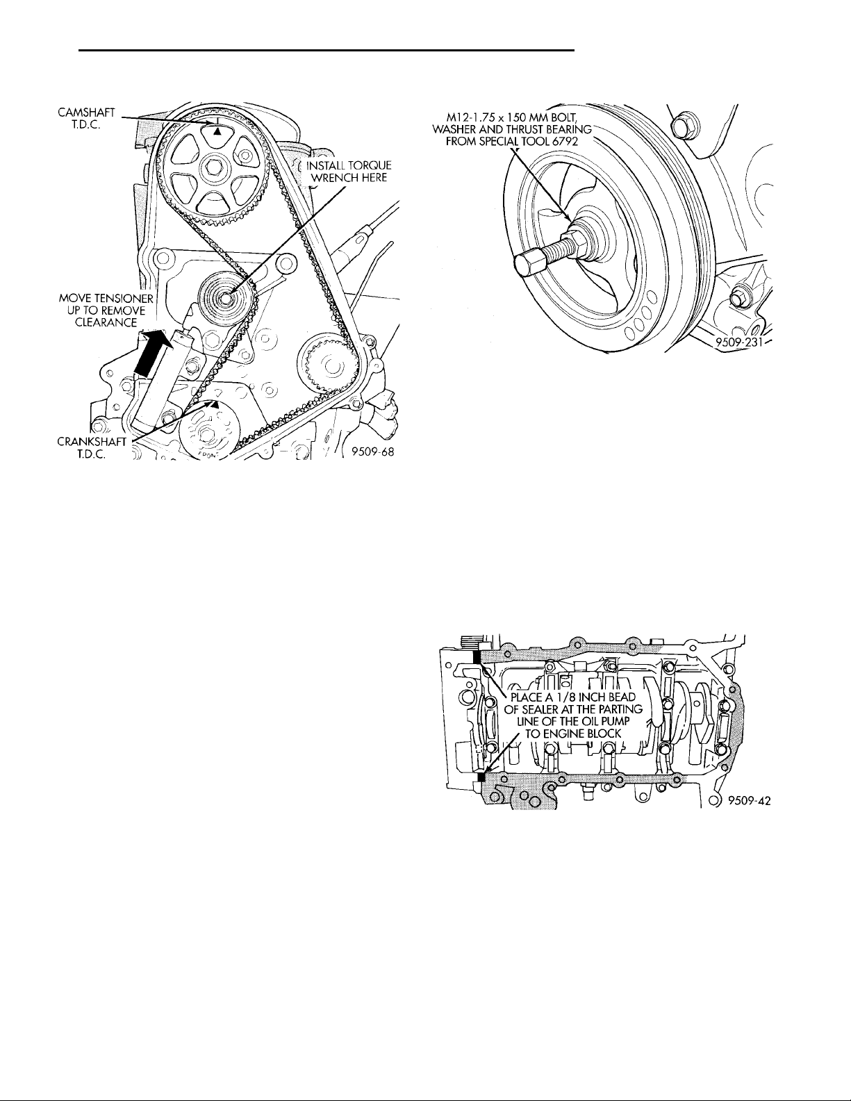
CAMSHAFTT.D.C. INSTALL TORQUEWRENCH HERECRANKSHAFT T.D.C.MOVE TEN-SIONER UP TOREMOVE CLEAR-ANCE
PL 2.0L SOHC ENGINE 9 - 31
REMOVAL AND INSTALLATION (Continued)
Fig. 54 Crankshaft Damper—Installation
(3) Remove front engine mount and bracket. Refer
to Engine Support Module Removal and Installation
in this section.
(4) Remove transmission inspection cover.
(5) If equipped with air conditioning remove oil fil-
Fig. 53 Adjusting Timing Belt Tension
pulley bracket and tighten fasteners to 31 N·m (275
in. lbs.) (Fig. 53).
(11) Pull tensioner plunger pin. Pretension is cor-
rect when pin can be removed and installed.
(12) Rotate crankshaft 2 revolutions and check the
alignment of the timing marks (Fig. 53).
(13) Install front half of timing cover.
(14) Install engine mount bracket.
(15) Install Right engine mount. Refer to proce-
dure outlined in this section.
(16) Remove jack from under engine.
(17) Install crankshaft damper using M12-1.75 x
150 mm bolt, washer, thrust bearing and nut from
Special Tool 6792. Install crankshaft damper bolt and
tighten to 142 N·m (105 ft. lbs.) (Fig. 54).
(18) Install accessory drive belts. Refer to Group 7,
Cooling System Accessory Drive section for procedure.
(19) Raise vehicle on hoist and install right inner
splash shield.
(20) Perform camshaft and crankshaft timing
relearn. Refer to Group 25, Emission Control Systems for procedure.
OIL PAN
REMOVAL
(1) Drain engine oil.
(2) Remove transmission bending bracket. Refer to
Engine Support Module Removal and Installation in
this section.
ter and adaptor. Refer to Oil Filter Adapter Removal
and Installation in this section.
(6) Remove oil pan.
(7) Clean oil pan and all gasket surfaces.
PLACE A 1/8 INCH BEAD OFSEALER AT THE PARTING LINEOF THE OIL PUMP TO ENGINEBLOCK
INSTALLATION
(1) Apply Mopar Silicone Rubber Adhesive Sealant
or equivalent at the oil pump to engine block parting
line (Fig. 55).
Fig. 55 Oil Pan Sealing
(2) Install a new oil pan gasket to pan.
(3) Install pan and tighten screws to 12 N·m (105
in. lbs.).
(4) Install oil filter and adaptor.
(5) Install transmission inspection cover.
(6) install front engine mount and bracket.
(7) Install transmission bending bracket.
(8) Install proper amount of oil. With oil filter 4.25
Liters (4.5 Qts.). Without oil filter 3.8 Liters (4.0
Qts.)
Page 32
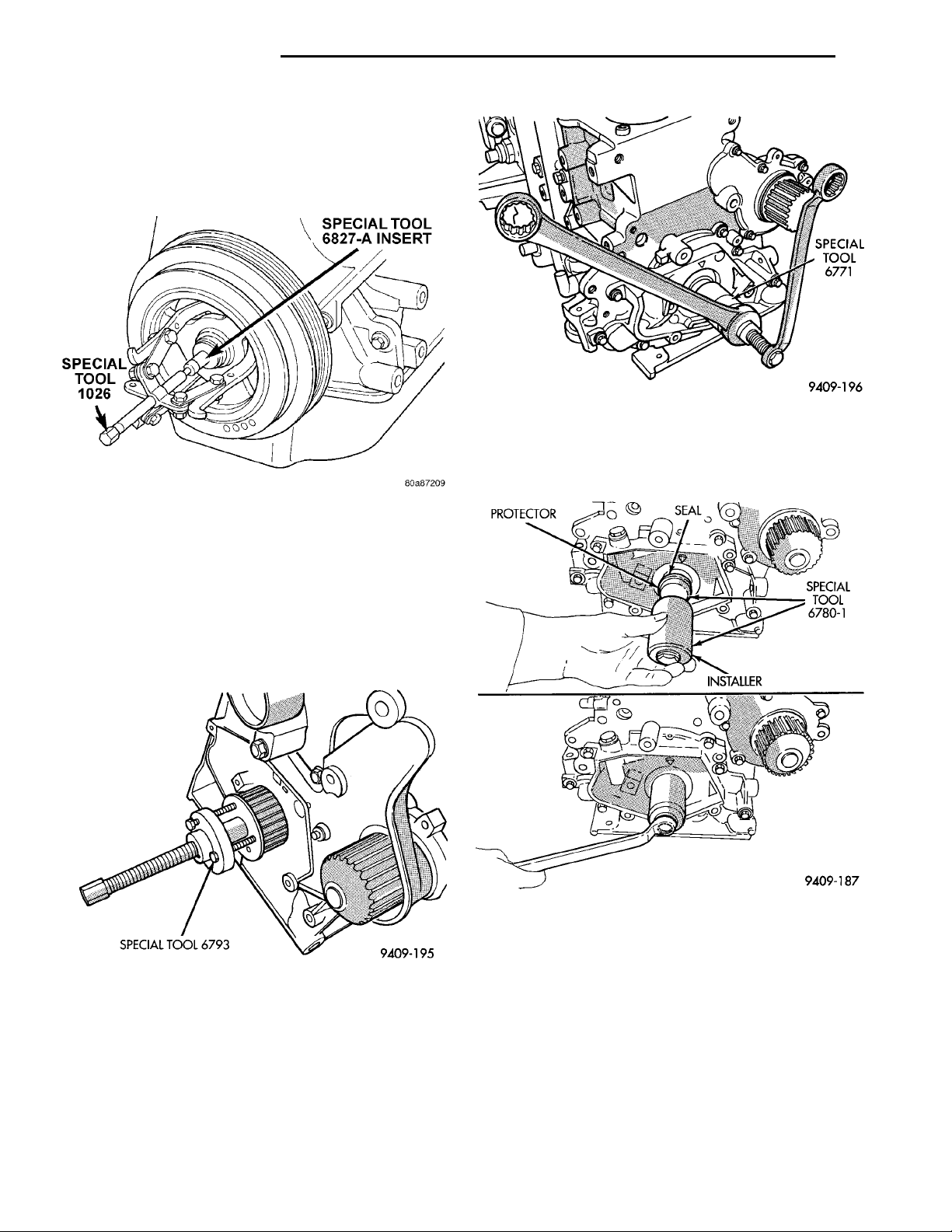
9 - 32 2.0L SOHC ENGINE PL
REMOVAL AND INSTALLATION (Continued)
FRONT CRANKSHAFT OIL SEAL
REMOVAL
(1) Using Special Tool 1026 and Insert 6827–A,
remove crankshaft damper (Fig. 56).
Fig. 56 Crankshaft Damper—Removal
(2) Remove outer timing belt cover and timing
belt. Refer to Timing Belt System outlined in this
section.
(3) Remove crankshaft sprocket using Special Tool
SPECIAL TOOL 6793
6793 and insert C- 4685-C2 (Fig. 57).
CAUTION: Do not nick shaft seal surface or seal
bore.
PROTECTOR
Fig. 58 Front Crankshaft Oil Seal—Removal
SEAL
SPECIALTOOL6780–1INSTALLER
(2) Place seal into opening with seal spring
towards the inside of engine. Install seal until flush
with cover.
Fig. 57 Crankshaft Sprocket—Removal
(4) Using Tool 6771 to remove front crankshaft oil
seal (Fig. 58). Do not damage the seal contact area
on the crankshaft.
INSTALLATION
(1) Install new seal by using Tool 6780–1 (Fig. 59).
Fig. 59 Front Crankshaft Oil Seal—Installation
(3) Install crankshaft sprocket (Fig. 60). Using
Special Tool 6792.
NOTE: Make sure the word “front” on the sprocket
is facing you.
(4) Install timing belt and covers. Refer to Timing
Belt System in this section for installation.
(5) Install crankshaft damper (Fig. 61). Use thrust
bearing/washer and 12M-1.75 x 150 mm bolt from
Special Tool 6792. Install crankshaft damper bolt and
tighten to 142 N·m (105 ft. lbs.)
Page 33
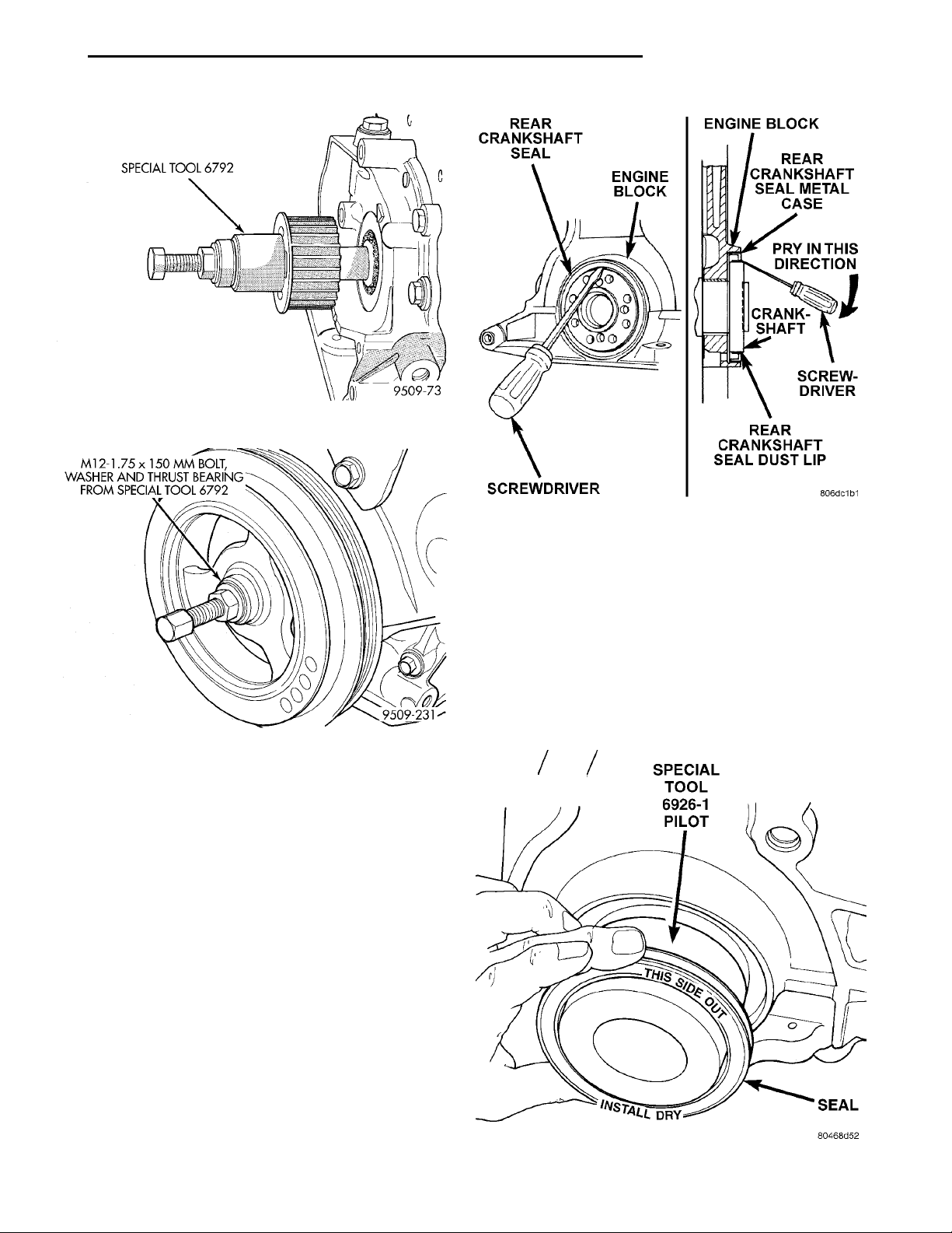
M12 — 1.75 3 150 MM BOLT,WASHER AND THRUSTBEARING FROM SPECIALTOOL 6792
SPECIAL TOOL 6792
REAR CRANKSHAFTSEAL ENGINEBLOCK ENGINE BLOCKREAR CRANK-SHAFT SEALMETAL CASEPRY IN THISDIRECTIONCRANK-SHAFTSCREW-DRIVERREAR CRANKSHAFT SEALDUST LIPSCREW-DRIVER
PL 2.0L SOHC ENGINE 9 - 33
REMOVAL AND INSTALLATION (Continued)
Fig. 60 Crankshaft Sprocket—Installation
Fig. 61 Crankshaft Damper—Installation
REAR CRANKSHAFT SEAL
REMOVAL
(1) Insert a 3/16 flat bladed screwdriver between
the dust lip and the metal case of the crankshaft
seal. Angle the screwdriver (Fig. 62) through the dust
lip against metal case of the seal. Pry out seal.
CAUTION: Do not permit the screwdriver blade to
contact crankshaft seal surface. Contact of the
screwdriver blade against crankshaft edge (chamfer) is permitted.
Fig. 62 Rear Crankshaft Oil Seal—Removal
(2) Position seal over pilot tool. Make sure you can
read the words THIS SIDE OUT on seal (Fig. 63).
Pilot tool should remain on crankshaft during installation of seal. Ensure that the lip of the seal is facing
towards the crankcase during installation.
CAUTION: If the seal is driven into the block past
SPECIAL TOOL 6926–1PILOT SEAL
flush, this may cause an oil leak.
(3) Drive the seal into the block using Special Tool
6926-2 and handle C-4171 (Fig. 64) until the tool bottoms out against the block (Fig. 65).
INSTALLATION
CAUTION: If burr or scratch is present on the
crankshaft edge (chamfer), cleanup with 400 grit
sand paper to prevent seal damage during installation of new seal.
NOTE: When installing seal, no lube on seal is needed.
(1) Place Special Tool 6926-1 on crankshaft. This is
a pilot tool with a magnetic base (Fig. 63).
Fig. 63 Rear Crankshaft Seal and Special Tool 6926-1
Page 34
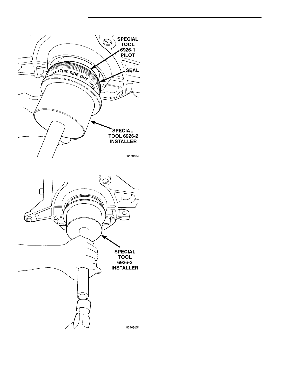
SPECIALTOOL6926–1PILOT
SPECIAL TOOL6792–2 INSTALLER
SPECIALTOOL6926–2INSTALLER
SEAL
9 - 34 2.0L SOHC ENGINE PL
REMOVAL AND INSTALLATION (Continued)
CRANKSHAFT
REMOVAL
(1) Remove oil filter and adapter from bedplate.
(2) Remove oil pan.
(3) Remove crankshaft sprocket and oil pump both
procedures outlined in this section.
(4) Remove all main bearing cap and bedplate
bolts from the engine block (Fig. 66).
(5) Using a mallet tap the bedplate loose from the
engine block dowel pins.
CAUTION: Do not pry up on one side of the bedplate. Damage may occur to cylinder block and bedplate alignment.
(6) Bedplate should be removed evenly from the
cylinder block dowel pins.
(7) Lift out crankshaft from cylinder block. Be sure
not to damage the main bearings or journals when
removing the crankshaft.
Fig. 64 Crankshaft Seal Special Tool 6926-2
CRANKSHAFT MAIN BEARINGS LOCATION
The crankshaft is supported in five main bearings.
All upper bearing shells in the crankcase have oil
grooves. All lower bearing shells installed in the (bedplate) main bearing cap are plain. Crankshaft end
play is controlled by a flanged bearing on the number
three main bearing journal (Fig. 67).
NOTE: The upper and lower main Bearing shells
are Not interchangeable. The lower shells have a
revised tab to prevent improper installation.
CRANKSHAFT MAIN JOURNALS INSPECTION
The crankshaft journals should be checked for
excessive wear, taper and scoring. Limits of taper or
out-of-round on any crankshaft journals should be
held to .025 mm (.001 inch). Journal grinding should
not exceed .305 mm (.012 inch) under the standard
journal diameter. DO NOT grind thrust faces of
Number 3 main bearing. DO NOT nick crank pin or
bearing fillets. After grinding, remove rough edges
from crankshaft oil holes and clean out all passages.
CAUTION: With the nodular cast iron crankshafts
used it is important that the final paper or cloth polish after any journal regrind be in the same direction as normal rotation in the engine.
Fig. 65 Rear Crankshaft Seal—Installation
Upper and lower Number 3 bearing halves are
flanged to carry the crankshaft thrust loads and are
NOT interchangeable with any other bearing halves
in the engine (Fig. 67). All bearing cap bolts removed
during service procedures are to be cleaned and oiled
before installation. Bearing shells are available in
standard and the following undersized: 0.016 mm
Page 35
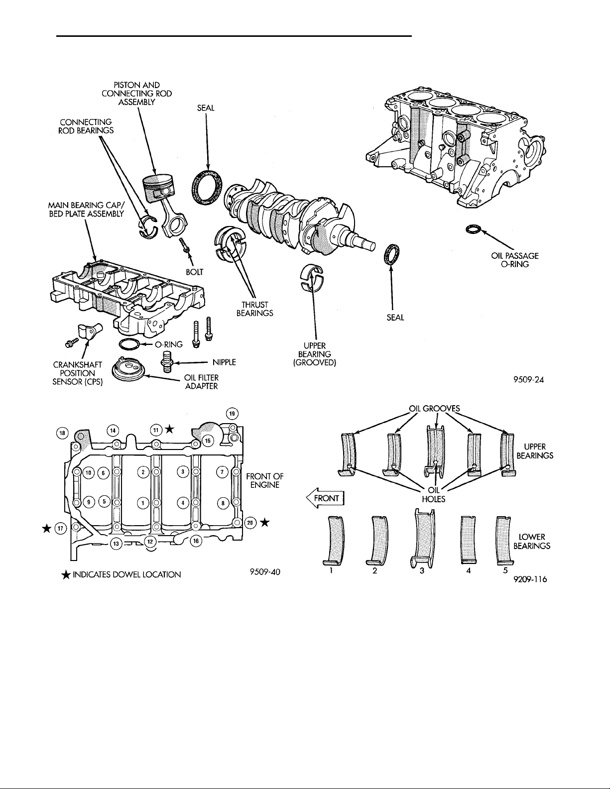
PISTON AND CONNECT-ING ROD ASSEMBLY SEAL OIL PASSAGEO-RINGSEALUPPER BEARING(GROOVED)THRUSTBEARINGSNIPPLEOIL FILTER ADAPTERO-RINGCRANKSHAFTPOSITION SEN-SOR (CPS) BOLTMAIN BEARING CAP/BED PLATE ASSEMBLYCONNECTING RODBEARINGS
FRONTOFENGINEINDICATES DOWEL LOCA-TION
OIL GROOVES UPPERBEARINGSLOWERBEARINGSOIL HOLESFRONT
PL 2.0L SOHC ENGINE 9 - 35
REMOVAL AND INSTALLATION (Continued)
Fig. 66 Bedplate Bolts
(.0006 inch), .032 mm (.0012 inch), .250 mm (.010
inch). Never install an undersize bearing that will
reduce clearance below specifications.
INSTALLATION
(1) Install the main bearing shells with the lubrication groove in the cylinder block. Install O-ring
into recess in the block (Fig. 68).
(2) Make certain oil holes in block line up with oil
hole in bearings and bearing tabs seat in the block
tab slots.
Fig. 67 Main Bearing Identification
CAUTION: Do Not get oil on the bedplate mating
surface. It will affect the sealer ability to seal the
bedplate to cylinder block.
(3) Oil the bearings and journals and install
crankshaft and O-ring in cylinder block.
CAUTION: Use only the specified anaerobic sealer
on the bedplate or damage may occur to the
engine.
Page 36
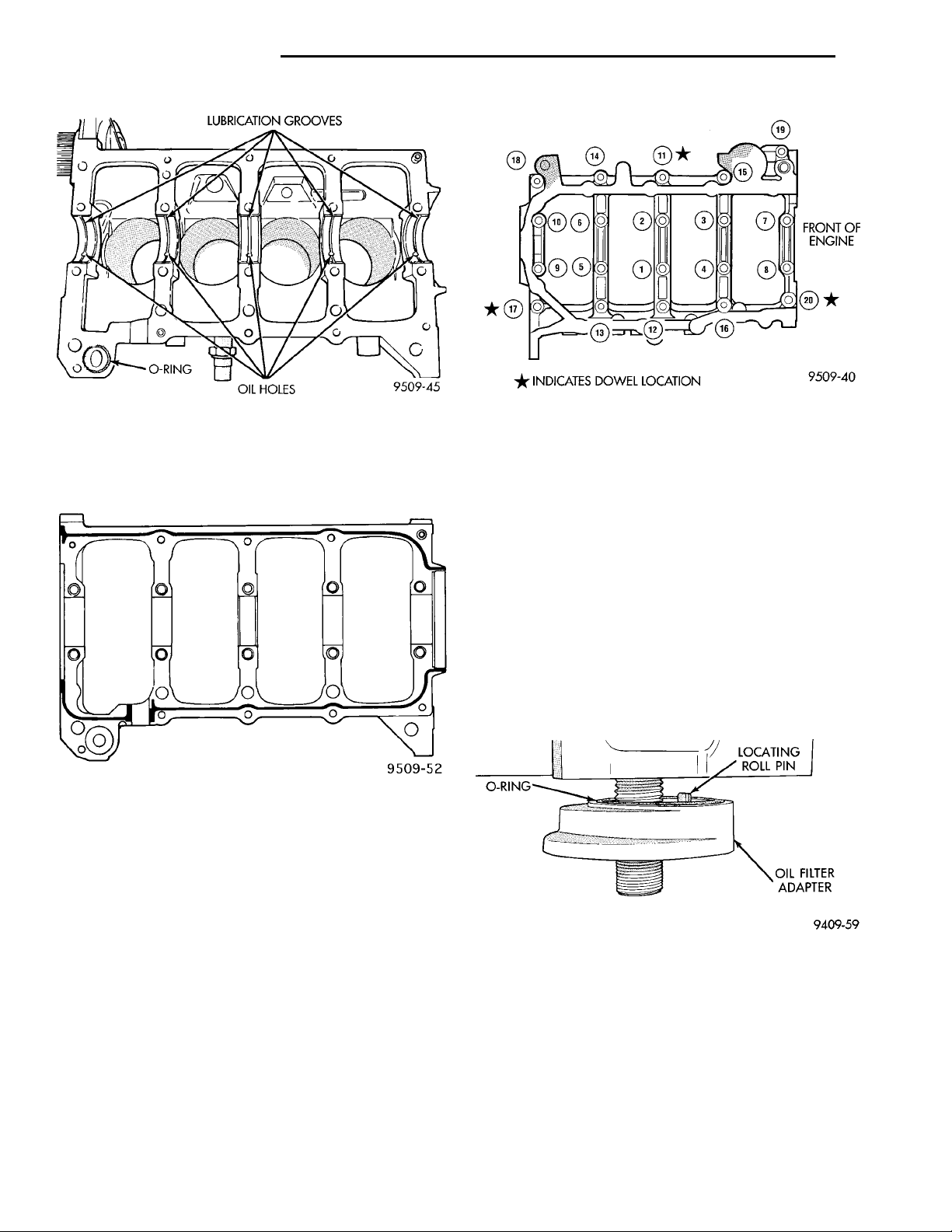
LUBRICATION GROOVESO-RING OIL HOLES
FRONTOFENGINEINDICATES DOWEL LOCA-TION
9 - 36 2.0L SOHC ENGINE PL
REMOVAL AND INSTALLATION (Continued)
Fig. 68 Installing Main Bearing Upper Shell
(4) Apply 1.5 to 2.0 mm (0.059 to 0.078 in.) bead of
Mopar Torque Cure Gasket Maker to cylinder block
as shown in (Fig. 69).
Fig. 69 Main Bearing Caps/Bedplate Sealing
(5) Install lower main bearings into main bearing
cap/bedplate. Make certain the bearing tabs are
seated into the bedplate slots. Install the main bearing/bedplate into engine block.
(6) Before installing the bolts the threads should
be oiled with clean engine oil, wipe off any excess oil.
(7) Install main bearing bedplate to engine block
bolts 11, 17 and 20 finger tight. Tighten this bolts
down together until the bedplate contacts the cylinder block. Torque bolts to 30 N·m (22 ft. lbs.) (Fig.
70).
(8) Install main bearing bedplate to engine block
bolts (1 thru 10) and torque each bolt to 81 N·m (60
ft. lbs.) in sequence shown in (Fig. 70).
(9) Install main bearing bedplate to engine block
bolts (11 thru 20), with baffle studs in positions 12,
13 and 16 and torque each bolt to 30 N·m (22 ft. lbs.)
in sequence shown in (Fig. 70).
Fig. 70 Main Bearing Caps/Bedplate Torque
Sequence
(10) After the main bearing bedplate is installed,
check the crankshaft turning torque. The turning
torque should not exceed 5.6 N·m (50 in. lbs.).
(11) Install oil pump. If crankshaft end play is to
be checked refer to service procedures in this section.
(12) Install crankshaft sprocket.
(13) Install oil filter adapter and filter. Refer to
procedure outlined in this section.
OIL FILTER ADAPTER
REMOVE AND INSTALL
Ensure O-ring is in the groove on adapter. Align
roll pin into engine block and tighten assembly to 80
N·m (60 ft. lbs.) (Fig. 71).
Fig. 71 Engine Oil Filter Adapter to Engine Block
OIL FILTER
REMOVE AND INSTALL
CAUTION: When servicing the oil filter (Fig. 72)
avoid deforming the filter, install tool band strap
against the seam at the base of the filter. The seam,
joining the can to the base is reinforced by the
base plate.
Page 37
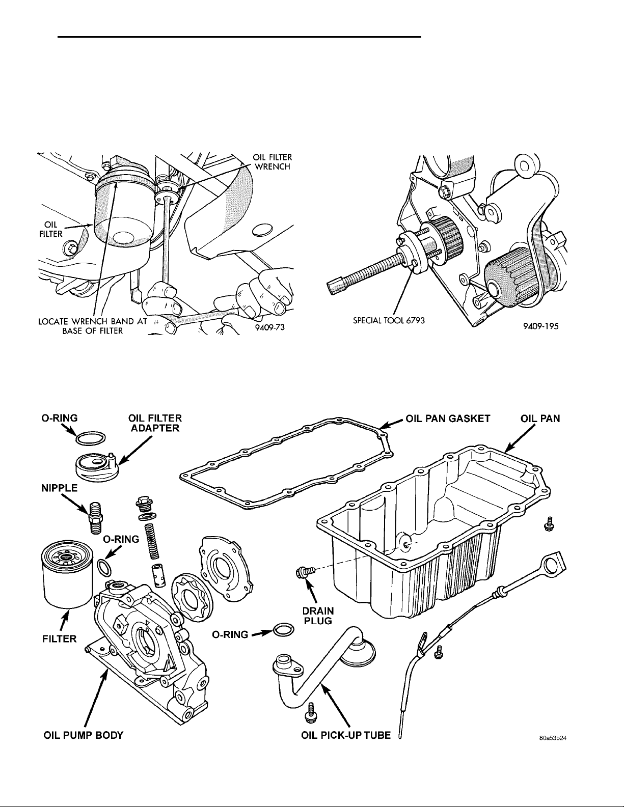
OIL FILTER OIL FILTERWRENCHLOCATE WRENCH BAND ATBASE OF FILTER
O-RINGOIL FILTER ADAPTEROIL PAN GASKETOIL PANOIL PICK-UP TUBEDRAIN PLUGO-RINGOIL PUMP BODYFILTERO-RINGNIPPLE
PL 2.0L SOHC ENGINE 9 - 37
REMOVAL AND INSTALLATION (Continued)
(1) Turn counterclockwise to remove.
(2) To install, lubricate new filter gasket. Check
filter mounting surface. The surface must be smooth,
flat and free of debris or old pieces of rubber. Screw
filter on until gasket contacts base. Tighten to 21
N·m (15 ft. lbs.).
Fig. 72 Engine Oil Filter
OIL PUMP
REMOVAL
(1) Disconnect negative battery cable.
(2) Remove Timing Belt. Refer to Timing Belt Sys-
tem, in this section.
SPECIAL TOOL 6793
(3) Remove Oil Pan. Refer to Oil Pan Removal in
this section.
(4) Remove Crankshaft Sprocket using Special Tool
6793 and insert C4685–C2 (Fig. 73).
Fig. 73 Crankshaft Sprocket—Removal
(5) Remove oil pick-up tube.
(6) Remove oil pump, (Fig. 74) and front crank-
shaft seal.
Fig. 74 Oil Pump and Tube
Page 38
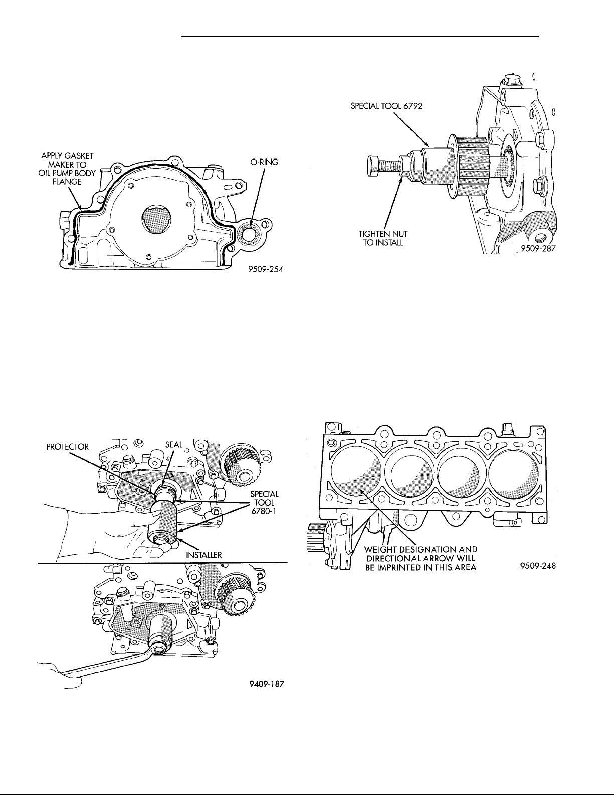
9 - 38 2.0L SOHC ENGINE PL
REMOVAL AND INSTALLATION (Continued)
INSTALLATION
(1) Make sure all surfaces are clean and free of oil
and dirt.
(2) Apply Mopar Gasket Maker to oil pump as
shown in (Fig. 75). Install oil ring into oil pump body
discharge passage.
Fig. 77 Crankshaft Sprocket—Installation
Fig. 75 Oil Pump Sealing
(3) Prime oil pump before installation.
(4) Align oil pump rotor flats with flats on crankshaft as you install the oil pump to the block.
NOTE: Front crankshaft seal MUST be out of pump
to align, or damage may result.
PROTECTOR
SEAL
SPECIALTOOL6780–1INSTALLER
(5) Torque all oil pump attaching bolts to 28 N·m
(250 in. lbs.)
(6) Install new front crankshaft seal using Special
Tool 6780 (Fig. 76).
(9) Install Timing Belt. Refer to Timing Belt
Installation in this section.
PISTON AND CONNECTING ROD
REMOVAL
(1) Remove top ridge of cylinder bores with a reliable ridge reamer before removing pistons from cylinder block. Be sure to keep tops of pistons
covered during this operation . Mark piston with
matching cylinder number (Fig. 78).
Fig. 76 Front Crankshaft Seal—Installation
(7) Install crankshaft sprocket, using Special Tool
6792 (Fig. 77).
(8) Install oil pump pick-up tube and oil pan.
Fig. 78 Piston Markings
(2) Remove oil pan. Scribe the cylinder number on
the side of the rod and cap (Fig. 79) for identification.
(3) Pistons will have a stamping in the approximate location shown in (Fig. 78). These stamps will
be either a directional arrow or a weight identification for the assembly. L is for light and H is for
heavy. These assemblies should all be the same
weight class. Service piston assemblies are marked
with a S and can be used with either L or H production assemblies. The weight designation stamps
should face toward the timing belt side of the engine.
Page 39
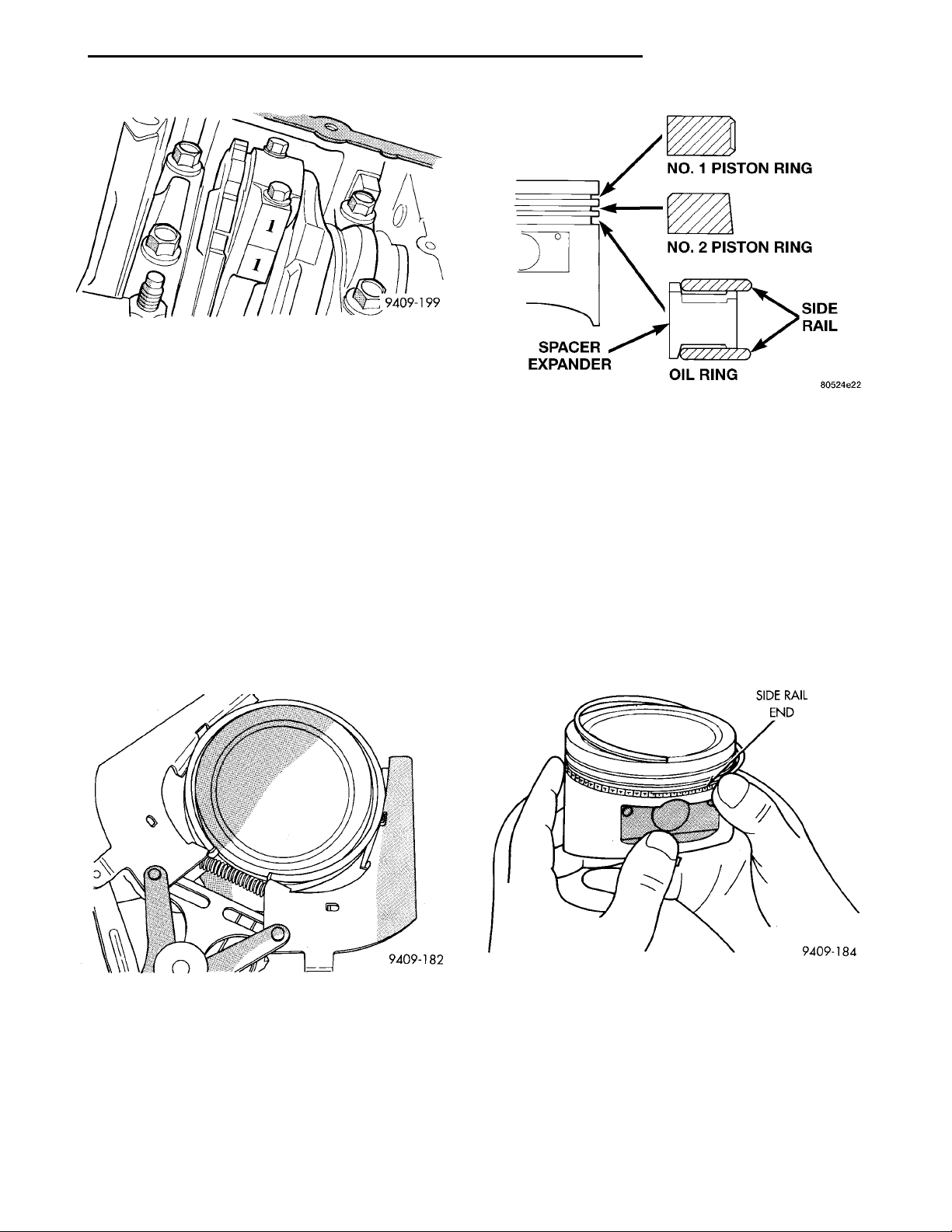
NO. 1 PISTON RINGNO. 2 PISTON RING SIDE RAILOIL RINGSPACEREXPANDER
SIDE RAIL END
PL 2.0L SOHC ENGINE 9 - 39
REMOVAL AND INSTALLATION (Continued)
Fig. 79 Identify Connecting Rod to Cylinder
(4) Pistons and connecting rods must be removed
from top of cylinder block. Rotate crankshaft so that
each connecting rod is centered in cylinder bore.
(5) Remove connecting rod cap bolts Do not use
old bolts if reinstalling connecting rod. Push
each piston and rod assembly out of cylinder bore.
CAUTION: Install piston rings in the following
order:
Fig. 81 Piston Ring Installation
NOTE: Be careful not to nick crankshaft journals.
(6) After removal, install bearing cap on the mating rod.
(7) Piston and Rods are serviced as an assembly.
PISTON RING—REMOVAL
(1) ID mark on face of upper and intermediate piston rings must point toward piston crown.
(2) Using a suitable ring expander, remove upper
and intermediate piston rings (Fig. 80).
a. Oil ring expander.
b. Upper oil ring side rail.
c. Lower oil ring side rail.
d. No. 2 Intermediate piston ring.
e. No. 1 Upper piston ring.
f. Install the side rail by placing one end between
the piston ring groove and the expander. Hold end
firmly and press down the portion to be installed
until side rail is in position. Do not use a piston
ring expander (Fig. 82).
Fig. 80 Piston Rings—Removing and Installing
(3) Remove the upper oil ring side rail, lower oil
ring side rail and then oil ring expander from piston.
(4) Clean ring grooves of any carbon deposits.
PISTON RINGS—INSTALLATION
(1) Install rings with manufacturers I.D. mark fac-
ing up, to the top of the piston (Fig. 81).
Fig. 82 Installing Side Rail
(2) Install upper side rail first and then the lower
side rail.
(3) Install No. 2 piston ring and then No. 1 piston
ring (Fig. 81).
(4) Position piston ring end gaps as shown in (Fig.
83).
(5) Position oil ring expander gap at least 45° from
the side rail gaps but not on the piston pin center or
Page 40
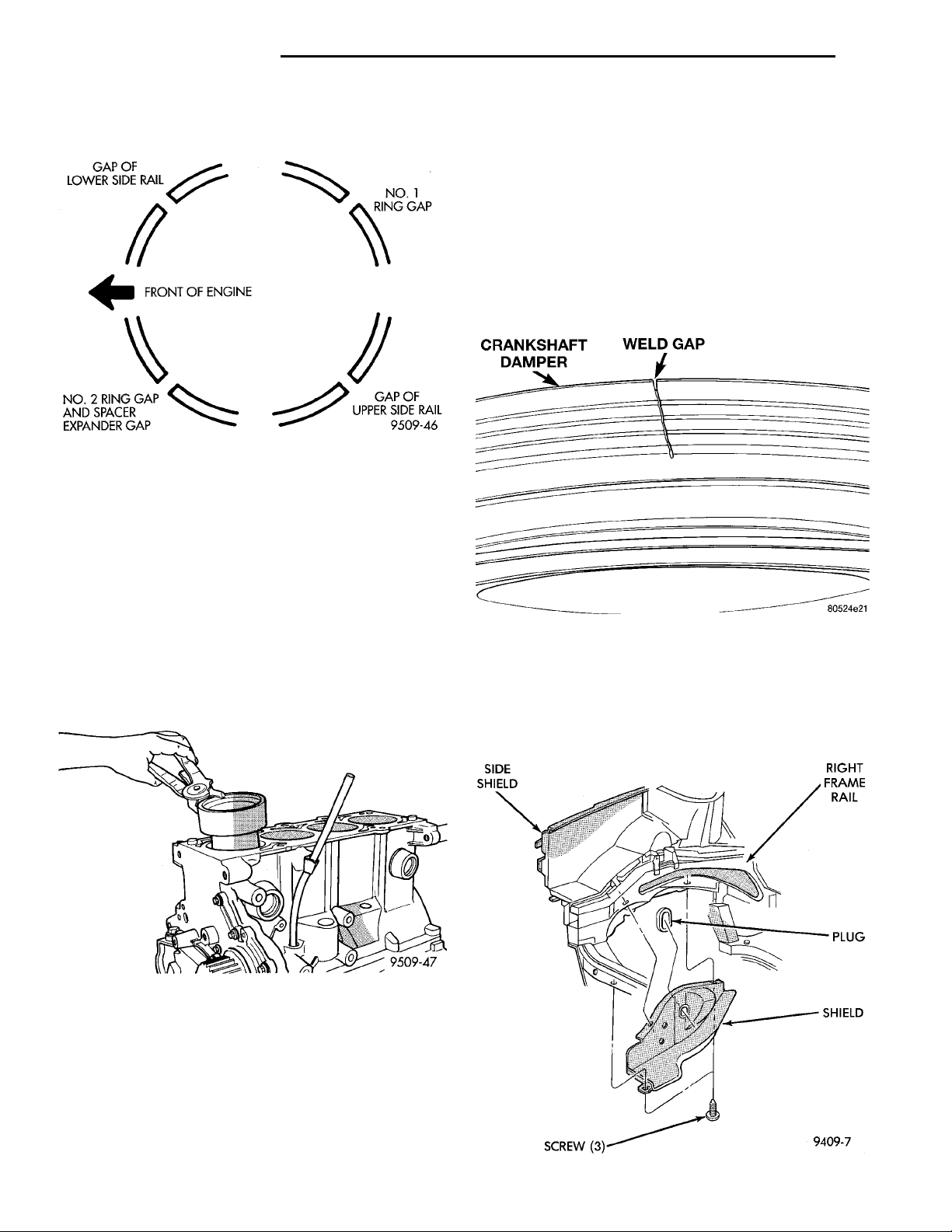
GAP OF LOWERSIDE RAIL NO. 1 RING GAPGAP OF UPPERSIDE RAILNO. 2 RING GAP ANDSPACER EXPANDERGAP FRONT OF ENGINE
CRANKSHAFTDAMPER WELD GAP
9 - 40 2.0L SOHC ENGINE PL
REMOVAL AND INSTALLATION (Continued)
on the thrust direction. Staggering ring gap is important for oil control.
Fig. 83 Piston Ring End Gap Position
PISTON AND ROD —INSTALLATION
(1) Before installing pistons and connecting rod
assemblies into the bore, be sure that compression
ring gaps are staggered so that neither is in line with
oil ring rail gap.
(2) Before installing the ring compressor, make
sure the oil ring expander ends are butted and the
rail gaps located as shown in (Fig. 83).
(3) Immerse the piston head and rings in clean
engine oil, slide the ring compressor, over the piston
(Fig. 84). Be sure position of rings does not
change during this operation .
rod and piston assembly into cylinder bore and guide
rod over the crankshaft journal.
(6) Tap the piston down in cylinder bore, using a
hammer handle. At the same time, guide connecting
rod into position on connecting rod journal.
(7) Install rod caps. Install New bolts and tighten
to 27 N·m (20 ft.lb.) Plus 1/4 turn.
VIBRATION DAMPER
NOTE: If a gap is found in the crankshaft damper,
in the area where the Poly-V Generator belt rides
this is normal and is acceptable (Fig. 85).
Fig. 85 Weld Gap
REMOVAL
SIDESHIELD RIGHT FRAMERAILPLUGSHIELDSCREW(3)
(1) Remove accessory drive belts. Refer to Group 7,
Cooling System for procedure outlined in that section.
(2) Raise vehicle on a hoist and remove right inner
splash shield (Fig. 86).
Fig. 84 Installing Piston
(4) The weight stamp designation L or H will be in
the front half of the piston should face toward the
front of the engine for SOHC engine. The arrow
should face toward the front of the engine for DOHC
engine (Fig. 78).
(5) Rotate crankshaft so that the connecting rod
journal is on the center of the cylinder bore. Insert
Fig. 86 Right Inner Splash Shield
Page 41
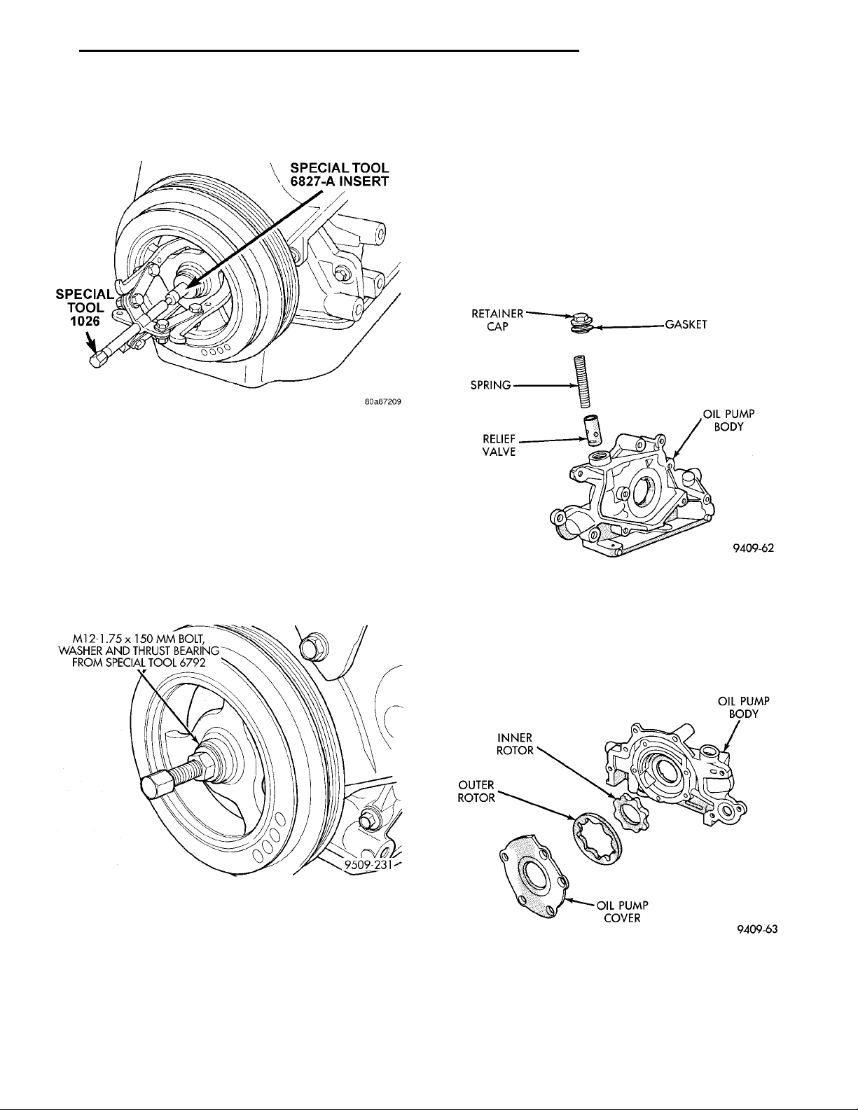
SPECIAL TOOL 6827–AINSERTSPECIAL TOOL 1026
M12 — 1.75 3 150 MM BOLT,WASHER AND THRUSTBEARING FROM SPECIALTOOL 6792
PL 2.0L SOHC ENGINE 9 - 41
REMOVAL AND INSTALLATION (Continued)
(3) Remove crankshaft damper bolt. Remove
damper using the large side of Special Tool 1026 and
insert 6827–A (Fig. 87).
Fig. 87 Crankshaft Damper—Removal
INSTALLATION
(1) Install crankshaft damper using M12-1.75 x
150 mm bolt, washer, thrust bearing and nut from
Special Tool 6792. Install crankshaft damper bolt and
tighten to 142 N·m (105 ft. lbs.) (Fig. 88).
(2) Install accessory drive belts. Refer to Group 7,
Cooling System Accessory Drive section for procedure.
(3) Raise vehicle on hoist and install right inner
splash shield.
DISASSEMBLY AND ASSEMBLY
RETAINER CAP GASKETOIL PUMP BODYRELIEFVALVESPRING
OIL PUMPBODYOIL PUMP COVEROUTERROTOR INNER ROTOR
OIL PUMP
(1) To remove the relief valve, proceed as follows:
(2) Remove the threaded plug and gasket from the
oil pump (Fig. 89).
CAUTION: Oil pump pressure relief valve must be
installed as shown in (Fig. 89) or serious damage
may occur.
(3) Remove spring and relief valve (Fig. 89).
Fig. 89 Oil Pressure Relief Valve
(4) Remove oil pump cover screws, and lift off
cover.
(5) Remove pump rotors.
(6) Wash all parts in a suitable solvent and inspect
carefully for damage or wear (Fig. 90).
Fig. 88 Crankshaft Damper—Installation
Fig. 90 Oil Pump
Page 42
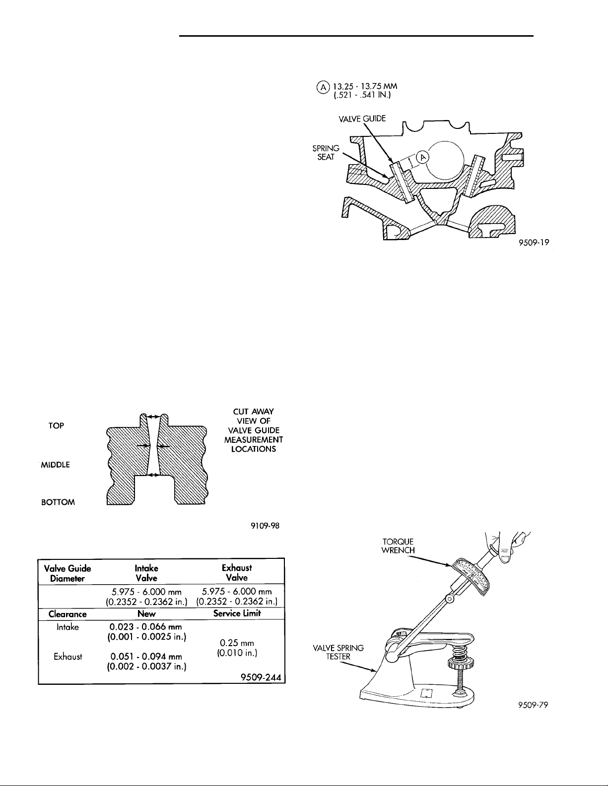
TOPMIDDLEBOTTOM CUT AWAY VIEW OFVALVE GUIDE MEA-SUREMENT LOCA-TIONS
9 - 42 2.0L SOHC ENGINE PL
DISASSEMBLY AND ASSEMBLY (Continued)
VALVE SERVICE WITH THE CYLINDER HEAD REMOVED
REMOVAL
(1) With cylinder head removed, compress valve
springs using Special Tool C-3422–B or equivalent.
(2) Remove valve retaining locks, valve spring
retainers, valve stem seals and valve springs.
(3) Before removing valves, remove any burrs
from valve stem lock grooves to prevent damage to the valve guides. Identify valves to insure
installation in original location.
VALVE INSPECTION
(1) Clean valves thoroughly and discard burned,
warped and cracked valves.
(2) Measure valve stems for wear. Measure stem
about 60 mm beneath the valve lock grooves.
(3) If valve stems are worn more than 0.05 mm
(.002 in.), replace valve.
VALVE GUIDES
(1) Remove carbon and varnish deposits from
inside of valve guides with a reliable guide cleaner.
(2) Using a small hole gauge and a micrometer,
measure valve guides in 3 places top, middle and bottom (Fig. 91). Refer to (Fig. 92) for specifications.
Replace guides if they are not within specification.
TESTING VALVE SPRINGS
(1) Whenever valves have been removed for inspection, reconditioning or replacement, valve springs
should be tested Special Tool C-647. As an example,
the compression length of the spring to be tested is
33.34 mm (1-5/16 inches). Turn tool table until surface is in line with the 33.34 mm (1-5/16 inch) mark
on the threaded stud and the zero mark on the front.
Place spring over stud on the table and lift compressing lever to set tone device (Fig. 94). Pull on torque
wrench until ping is heard. Take reading on torque
wrench at this instant. Multiply this reading by two.
This will give the spring load at test length. Fractional measurements are indicated on the table for
finer adjustments. Discard the springs that do not
meet specifications. The Following specifications
apply to both intake and exhaust valve springs.
• Valve Closed Nominal Force— 67 lbs. @ 39.8 mm
(1.57 in.)
• Valve Open Nominal Force— 160 lbs. @ 32.6 mm
(1.28 in.)
Fig. 93 Valve Guide Height
TORQUE WRENCHVALVE SPRINGTESTER
Fig. 91 Checking Wear on Valve Guide—Typical
Fig. 92 Valve Guide Specifications
(3) Check valve guide height (Fig. 93).
Fig. 94 Testing a Valve Spring
Page 43
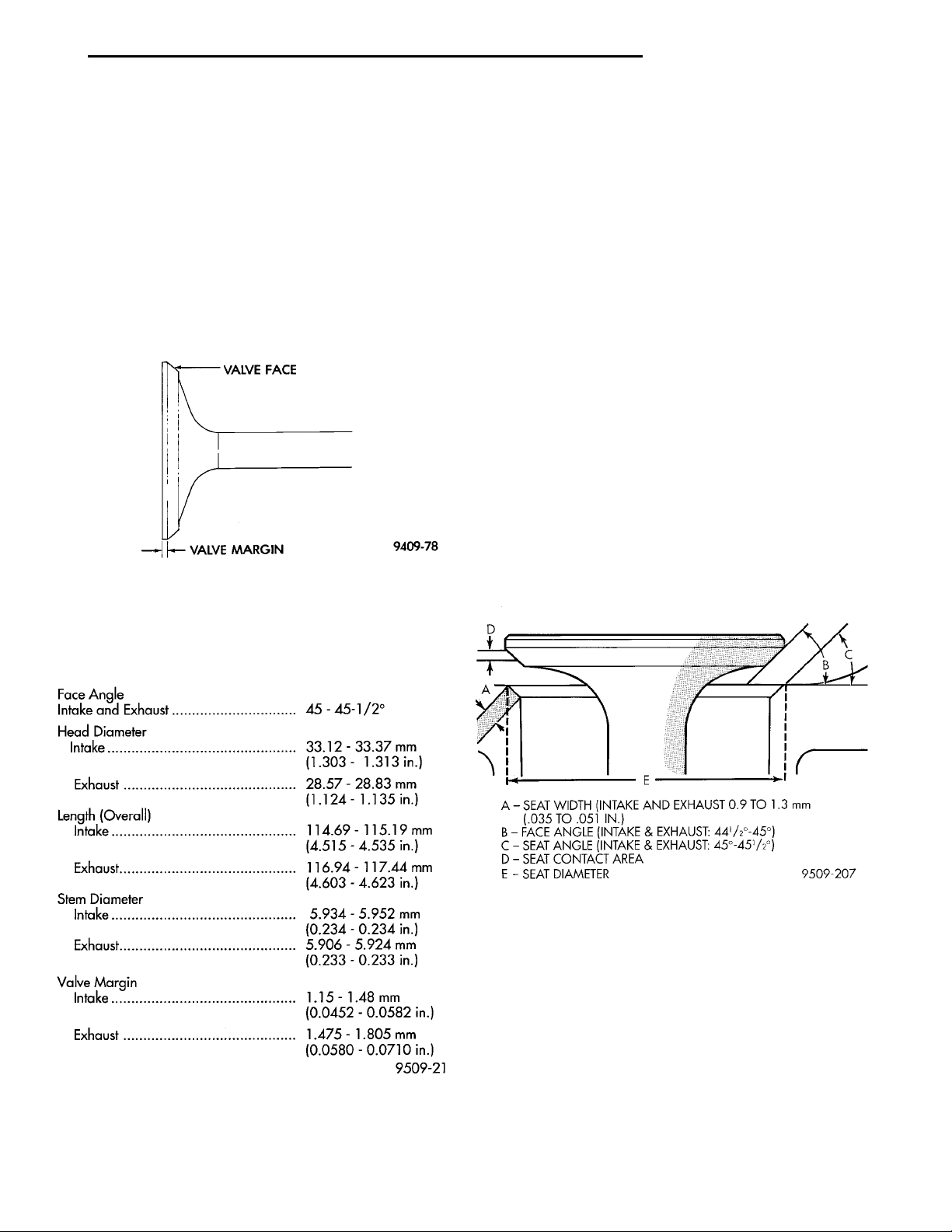
VALVE FACEVALVE MARGIN
PL 2.0L SOHC ENGINE 9 - 43
DISASSEMBLY AND ASSEMBLY (Continued)
(2) Verify springs are not distorted with a steel
square and surface plate, check springs from both
ends. If the spring is more than 1.5 mm (1/16 inch)
out of square, install a new spring.
REFACING VALVES AND VALVE SEATS
(1) The intake and exhaust valve seats and valve
face have a 45 degree angle.
(2) Inspect the remaining margin after the valves
are refaced (Fig. 95). Intake valves with less than
0.95 mm (1/32 inch.) margin and Exhaust valves
with less than 1.05 mm (3/64 inch) margin should be
discarded.
Fig. 95 Refacing Intake and Exhaust Valves
(3) When refacing valve seats, it is important that
the correct size valve guide pilot be used for reseating stones. A true and complete surface must be
obtained See (Fig. 96) for valve specification.
Total runout should not exceed. 0.051 mm (0.002
inch.) (total indicator reading).
(5) Inspect the valve seat with Prussian blue to
determine where the valve contacts the seat. To do
this, coat valve seat LIGHTLY with Prussian blue
then set valve in place. Rotate the valve with light
pressure. If the blue is transferred to the center of
valve face, contact is satisfactory. If the blue is transferred to top edge of the valve face, lower valve seat
with a 15 degrees stone. If the blue is transferred to
the bottom edge of valve face raise valve seat with a
65 degrees stone.
• Intake valve seat diameter is 33 mm (1.299 in.)
• Exhaust valve seat diameter is 28 mm (1.102
in.)
(6) Valve seats which are worn or burned can be
reworked, provided that correct angle and seat width
are maintained. The intake valve seat must be serviced when the valve seat width is 2.0 mm (0.079 in.)
or greater. The exhaust valve seat must be serviced
when the valve seat width is 2.5 mm (0.098 in.) or
A — SEAT WIDTH (INTAKE AND EXHAUST 0.9 TO 1.3 mm (.035 TO .051IN.)B — FACE ANGLE (INTAKE & EXHAUST: 441⁄2°–45°)C — SEAT ANGLE (INTAKE & EXHAUST: 45°-451⁄2°)D — SEAT CONTACT AREAE — SEAT DIAMETER
greater. Otherwise the cylinder head must be
replaced.
(7) When seat is properly positioned the width of
intake and exhaust seats should be 0.75 to 1.25 mm
(0.030 to 0.049 in.) (Fig. 97).
Fig. 96 Valve Specifications
(4) Measure the concentricity of valve seat and
valve guide using a valve seat runout dial indicator.
Fig. 97 Refacing Valve Seats
(8) Check valve tip to spring seat dimensions A
after grinding the valve seats or faces. Grind valve
tip to 43.51 - 44.57 mm (1.71 - 1.75 in.) for exhaust
valve and 45.01 - 46.07 mm (1.77 - 1.81 in.) for
intake valve over spring seat when installed in the
head (Fig. 98). The valve tip chamfer may need to be
reground to prevent seal damage when the valve is
installed.
CLEANING
Clean all valve guides, valves and valve spring
assemblies thoroughly with suitable cleaning solution
before reassembling.
Page 44
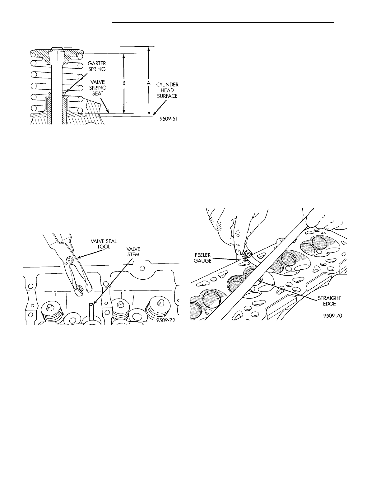
9 - 44 2.0L SOHC ENGINE PL
DISASSEMBLY AND ASSEMBLY (Continued)
in.) spacer under the valve spring seat to bring
spring height back within specification.
(5) Install rocker arm shafts as previously
described in this section.
(6) Checking dry lash. Dry lash is the amount of
clearance that exists between the base circle of an
installed cam and the rocker arm roller when the
adjuster is drained of oil and completely collapsed.
Specified dry lash is 1.17 mm (0.046 in.) for intake
and 1.28 mm (0.050 in.) for exhaust. After performing
dry lash check, refill adjuster with oil and allow 10
Fig. 98 Checking Spring Installed Height and Valve
Tip to Spring Seat Dimensions
VALVE INSTALLATION
(1) Coat valve stems with clean engine oil and
insert in cylinder head.
(2) Install new valve stem seals on all valves using
a valve stem seal tool (Fig. 99). The valve stem seals
should be pushed firmly and squarely over valve
guide.
CAUTION: If oversize valves are used, there is only
one oversize valve available. The same stem seal is
used on both the standard and oversize valve.
VALVE SEAL TOOL VALVE STEM
minutes for adjuster/s to bleed down before rotating
cam.
CLEANING AND INSPECTION
CYLINDER HEAD AND CAMSHAFT JOURNALS
INSPECTING CYLINDER HEAD
Cylinder head must be flat within 0.1 mm (0.004
inch) (Fig. 100).
Fig. 99 Valve Stem Oil Seal Tool
(3) Install valve springs and retainers. Compress
valve springs only enough to install locks, taking
care not to misalign the direction of compression.
Nicked valve stems may result from misalignment of
the valve spring compressor.
CAUTION: When depressing the valve spring
retainers with valve spring compressor the locks
can become dislocated. Check to make sure both
locks are in their correct location after removing
tool.
(4) Check the valve spring installed height B after
refacing the valve and seat (Fig. 98). Make sure measurements are taken from top of spring seat to the
bottom surface of spring retainer. If height is greater
than 40.18 mm (1.58 in.), install a 0.762 mm (0.030
Fig. 100 Checking Cylinder Head Flatness
Inspect cylinder head journals for wear.
Check camshaft journals for scratches and worn
areas. If light scratches are present, they may be
removed with 400 grit sand paper. If deep scratches
are present, replace the camshaft and check the cylinder head for damage. Replace the cylinder head if
worn or damaged. Check the lobes for pitting and
wear. If the lobes show signs of wear, check the corresponding rocker arm roller for wear or damage.
Replace rocker arm/hydraulic lash adjuster if worn or
damaged. If lobes show signs of pitting on the nose,
flank or base circle; replace the camshaft.
CLEANING
Remove all gasket material from cylinder head and
block. Be careful not to gouge or scratch the aluminum head sealing surface.
Page 45
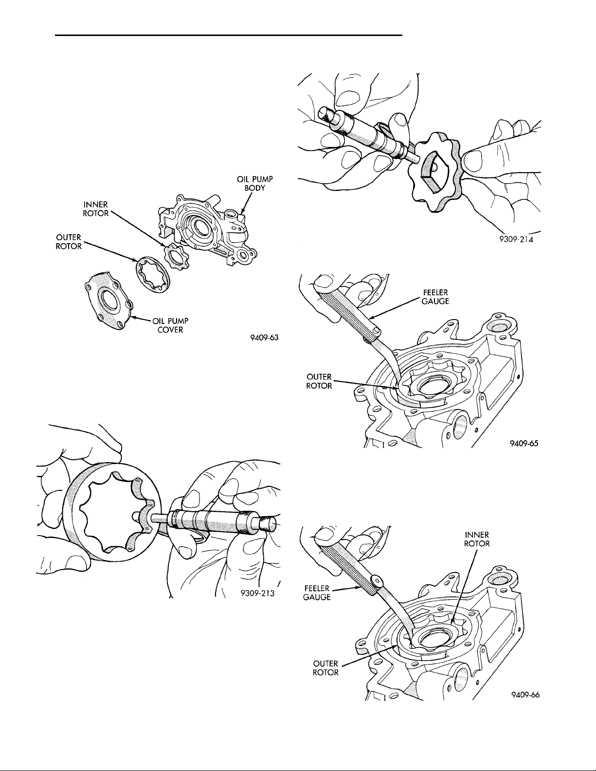
PL 2.0L SOHC ENGINE 9 - 45
CLEANING AND INSPECTION (Continued)
OIL PUMP
(1) Clean all parts thoroughly. Mating surface of
the oil pump should be smooth. Replace pump cover
if scratched or grooved.
(2) Lay a straightedge across the pump cover surface (Fig. 101). If a 0.076 mm (0.003 inch.) feeler
gauge can be inserted between cover and straight
edge, cover should be replaced.
Fig. 103 Measuring Inner Rotor Thickness
Fig. 101 Checking Oil Pump Cover Flatness
(3) Measure thickness and diameter of outer rotor.
If outer rotor thickness measures 7.64 mm (0.301
inch.) or less (Fig. 102), or if the diameter is 79.95
mm (3.148 inches) or less, replace outer rotor.
Fig. 102 Measuring Outer Rotor Thickness
(4) If inner rotor measures 7.64 mm (.301 inch) or
less replace inner rotor (Fig. 103).
(5) Slide outer rotor into pump housing, press to
one side with fingers and measure clearance between
rotor and housing (Fig. 104). If measurement is 0.39
mm (0.015 inch.) or more, replace housing only if
outer rotor is in specification.
Fig. 104 Measuring Outer Rotor Clearance in
INNERROTOR OUTER ROTORFEELER GAUGE
Housing
(6) Install inner rotor into pump housing. If clearance between inner and outer rotors (Fig. 105) is .203
mm (.008 inch) or more, replace both rotors.
Fig. 105 Measuring Clearance Between Rotors
Page 46
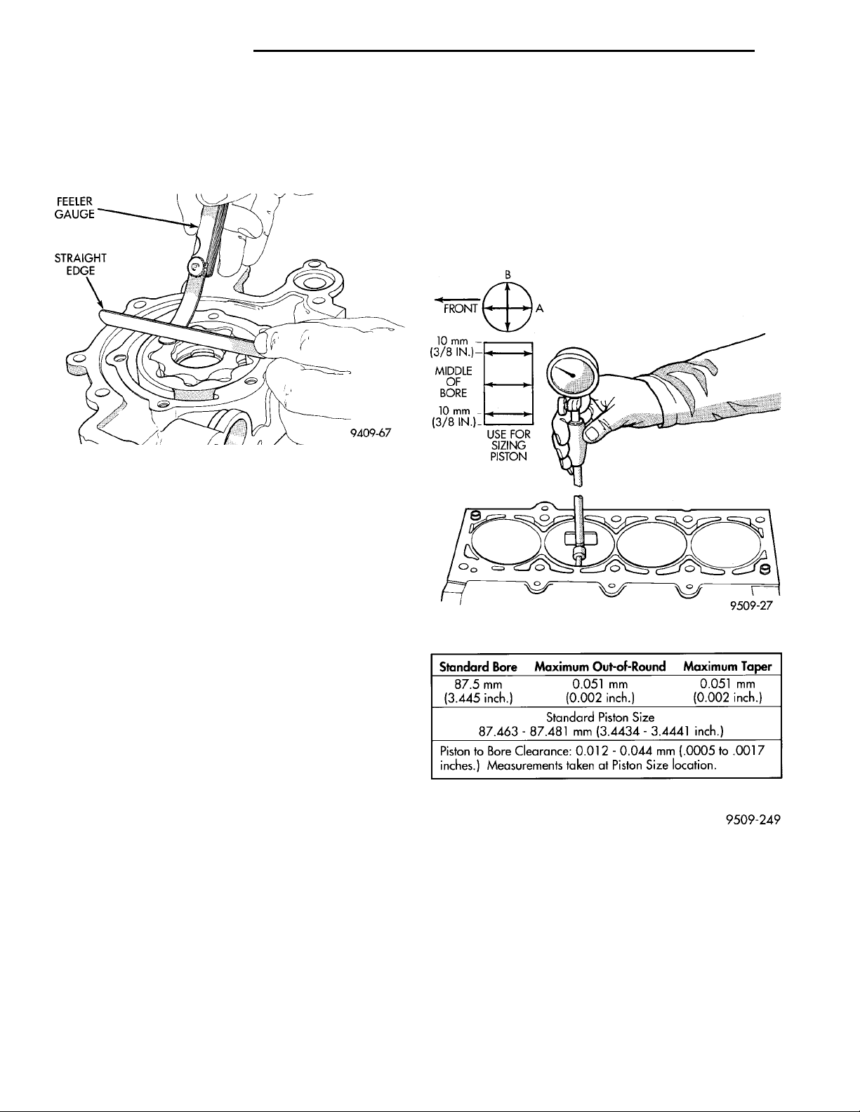
FEELERGAUGESTRAIGHTEDGE
FRONT MIDDLEOF BORE
USE FOR
SIZING
PISTON
9 - 46 2.0L SOHC ENGINE PL
CLEANING AND INSPECTION (Continued)
(7) Place a straightedge across the face of the
pump housing, between bolt holes. If a feeler gauge
of .102 mm (.004 inch) or more can be inserted
between rotors and the straightedge, replace pump
assembly (Fig. 106). ONLY if rotors are in specs.
Fig. 106 Measuring Clearance Over Rotors
(8) Inspect oil pressure relief valve plunger for
scoring and free operation in its bore. Small marks
may be removed with 400-grit wet or dry sandpaper.
(9) The relief valve spring has a free length of
approximately 60.7 mm (2.39 inches) it should test
between 18 and 19 pounds when compressed to 40.5
mm (1.60 inches). Replace spring that fails to meet
specifications.
(10) If oil pressure is low and pump is within specifications, inspect for worn engine bearings, damaged
or missing oil pick-up tube o-ring, clogged oil pick-up
tube screen, clogged oil filter and stuck open pressure relief valve or other reasons for oil pressure
loss.
specified clearances may be maintained. Refer to
Honing Cylinder Bores outlined in the Standard Service Procedures for specification and
procedures.
Measure the cylinder bore at three levels in directions A and B (Fig. 107). Top measurement should be
10 mm (3/8 inch) down and bottom measurement
should be 10 mm (3/8 inch.) up from bottom of bore.
Refer to (Fig. 108) for specifications.
Fig. 107 Checking Cylinder Bore Size
CYLINDER BLOCK AND BORE
(1) Clean cylinder block thoroughly and check all
core hole plugs for evidence of leaking.
(2) If new core plugs are installed, Refer to Engine
Core Plugs outlined in this section.
(3) Examine block and cylinder bores for cracks or
fractures.
CYLINDER BORE INSPECTION
The cylinder walls should be checked for out-ofround and taper with Tool C-119 (Fig. 107). The cylinder bore out-of-round is 0.050 mm (.002 inch)
maximum and cylinder bore taper is 0.051 mm (0.002
inch) maximum. If the cylinder walls are badly
scuffed or scored, the cylinder block should be
rebored and honed, and new pistons and rings fitted.
Whatever type of boring equipment is used, boring
and honing operation should be closely coordinated
with the fitting of pistons and rings in order that
Fig. 108 Cylinder Bore and Piston Specifications
Page 47

PL 2.0L SOHC ENGINE 9 - 47
SPECIFICATIONS
ENGINE 2.0L SOHC
Cylinder Block
Cylinder Bore Diameter .....87.4924 - 87.5076 mm
(3.4446 - 3.4452.in.)
Out-of-Round (Max.) ........0.051 mm (0.002 in.)
Taper (Max.) ..............0.051 mm (0.002 in.)
Pistons
Clearance 17.5 mm (11/16 in.)
from bottom of skirt ..........0.012 - 0.044 mm
(0.0004 - 0.0017 in.)
Weight ......................325-335grams
(11.47 - 11.82 oz.)
Land Clearance (Diametrical) ....0.734 - 0.797 mm
(0.029 - 0.031 in.)
Piston Length ...............64mm(2.520 in.)
Piston Ring Groove
Depth No. 1 ................3.989 - 4.188 mm
(0.157 - 0.165 in.)
Piston Ring Groove
Depth No. 2 ................4.462 - 4.661 mm
(0.176 - 0.184 in.)
Piston Ring Groove
Depth No. 3 ................3.847 - 4.131 mm
(0.151 - 0.163 in.)
Piston Pins
Clearance in Piston ............0.008 - 0.020 mm
(0.0003 - 0.0008 in.)
In Rod (Interference) ...........0.018 - 0.043 mm
(0.0007 - 0.0017 in.)
Diameter .................20.998 - 21.003 mm
(0.8267 - 0.8269 in.)
End Play ............................None
Length .....................74.75 - 75.25 mm
(2.943 - 2.963 in.)
Piston Rings
Ring Gap Top
Compression Ring ................0.23 - 0.52 mm
(0.009 - 0.020 in.)
Ring Gap 2nd
Compression Ring .............0.49 - 0.78 mm
(0.019 - 0.031 in.)
Ring Gap Oil Control
(Steel Rails) .................0.23 - 0.66 mm
(0.009 - 0.026 in.)
Ring Side Clearance Both
Compression Rings ..........0.025 - 0.065 mm
(0.0010 - 0.0026 in.)
Oil Ring (Pack) ...............0.004 - 0.178 mm
(0.0002 - 0.0070 in.)
Ring Width Compression Rings .....1.17 - 1.19 mm
(0.046 - 0.047 in.)
Oil Ring (Pack) ...............2.854 - 3.008 mm
(0.1124 - 0.1184 in.)
Connecting Rod
Bearing Clearance ............0.026 - 0.059 mm
(0.001 - 0.0023 in.)
Piston Pin Bore Diameter .......20.96 - 20.98 mm
(0.8252 - 0.8260 in.)
Large End Bore Diameter .....50.991 - 51.005 mm
(2.0075 - 2.0081 in.)
Side Clearance .................0.13 - 0.38 mm
(0.005 - 0.015 in.)
Total Weight (Less Bearing) ...........543grams
(1.20 lbs.)
Crankshaft
Connecting Rod Journal
Diameter ..............47.9924 - 48.0076 mm
(1.8894 - 1.8900 in.)
Out-of-Round (Max.) .......0.0035 mm (0.0001 in.)
Taper (Max.) ............0.0038 mm (0.0001 in.)
Main Bearing Diametrical
Clearance No.1-5 ..........0.022 - 0.062 mm
(0.0008 - 0.0024 in.)
End Play .....................0.09 - 0.24 mm
(0.0035 - 0.0094 in.)
Main Bearing Journals
Diameter ................51.9924 - 52.0076 mm
(2.0469 - 2.0475 in.)
Out-of-Round (Max.) .......0.0035 mm (0.0001 in.)
Taper (Max.) ............0.0038 mm (0.0001 in.)
ENGINE 2.0L SOHC
Rocker Arm Shaft
Rocker Arm Shaft Diameter ....19.996 – 19.984mm
(0.786 – 0.7867 in.)
Rocker Arm Shaft Retainers (Width)
Intake (All) ................28.46 mm (1.12 in.)
Exhaust .....................1&529.20 mm
(1.14in.) 2, 3, and
4 - 40.45 mm (1.59 in.)
Rocker Arm/Hydraulic Lash Adjuster *
Rocker Arm Inside Diameter ....20.00 – 20.02 mm
(0.787 – 0.788 in.)
Rocker Arm Shaft Clearance .....0.016 – 0.054 mm
(0.0006 – 0.0021 in.)
Body Diameter .............22.949 – 22.962 mm
(0.9035 – 0.9040 in.)
Plunger Travel Minimum
(Dry) ....................2.2mm(0.087 in.)
Rocker Arm Ratio ....................1.4to1
Camshaft
No.1 ......41.20 – 41.221 mm (1.622 – 1.6228 in.)
No.2 ........41.6 – 41.621 mm (1.637 – 1.638 in.)
No.3 ........42.0 – 42.021 mm (1.653 – 1.654 in.)
No.4 ........42.4 – 42.421 mm (1.669 – 1.670 in.)
No.5 .......42.8 – 42.821 mm (1.685 – 1.6858 in.)
Bearing Journal Diameter
No.1 .....41.128 – 41.147 mm (1.619 – 1.6199 in.)
No.2 ......41.528 – 41.547 mm (1.634 – 1.635 in.)
No.3 ......41.928 – 41.947 mm (1.650 – 1.651 in.)
No.4 ......42.328 – 42.374 mm (1.666 – 1.668 in.)
No.5 .....42.728 – 42.747 mm (1.682 – 1.6829 in.)
Diametrical Bearing
Clearance ................0.053 – 0.093 mm
(0.0027 – 0.003 in.)
Max. Allowable ............0.12 mm (0.0047 in.)
End Play ............0.05 – 0.39 mm (0.0059 in.)
Lift (Zero Lash )
Intake .....................7.8mm(0.307 in.)
Exhaust ..................7.03 mm (0.277 in.)
Page 48

9 - 48 2.0L SOHC ENGINE PL
SPECIFICATIONS (Continued)
Valve Timing Exhaust Valve
Closes (ATDC) .........................5.4°
Opens (BBDC) ........................43.7°
Duration ............................229.1°
Valve Timing Intake Valve **
Closes (ABDC) ........................41.1°
Opens (ATDC) .........................13.9°
Duration ............................207.2°
Valve Overlap ...........................0°
Cylinder Head
Material .....................Cast Aluminum
Gasket Thickness
(Compressed) .............1.15 mm (0.045 in.)
Valve Seat
Angle ................................45°
Runout (Max.) ...............0.050 mm (0.002)
Width (Finish) Intake and
Exhaust ...................0.75 – 1.25 mm
(0.030 – 0.049 in.)
Valve Guide Finished
Diameter I.D. ................5.975 – 6.000 mm
(.235 – .236 in.)
Guide Bore Diameter (Std.) ......11.0–11.02 mm
(0.4330 – 0.4338 in.)
Valves
Face Angle Intake and Exhaust .......45–45-1/2°
Head Diameter Intake .........32.12 – 33.37 mm
(1.303 – 1.313 in.)
Head Diameter Exhaust ........28.57 – 28.83 mm
(1.124 – 1.135 in.)
Valve Margin
Intake .......................1.15 – 1.48 mm
(0.0452 – 0.0582 in.)
Exhaust ....................1.475 – 1.805 mm
(0.058 – 0.071 in.)
Valve Length (Overall)
Intake ...................114.69 – 115.19 mm
(4.515 – 4.535 in.)
Exhaust ..................109.59 – 110.09 mm
(4.603 – 4.623 in.)
Valve Stem Tip Height
Intake .....................45.01 – 46.07 mm
(1.77 – 1.81 in.)
Exhaust ....................43.51 – 44.57 mm
(1.71 – 1.75 in.)
Stem Diameter
Intake .....................5.934 – 5.952 mm
(0.234 – 0.234 in.)
Exhaust ....................5.906 – 5.924 mm
(0.233 – 0.233 in.)
Stem to Guide Clearance
Intake .....................0.048 – 0.066 mm
(0.0018 – 0.0025 in.)
Exhaust ...................0.0736 – 0.094 mm
(0.0029 – 0.0037 in.)
Max. Allowable Intake .......0.076 mm (0.003 in.)
Max. Allowable Exhaust ......0.101 mm (0.004 in.)
Valve Springs
Free Length (Approx.) ........44.4 mm (1.747 in.)
Nominal Force
(Valve closed) .............91N·[email protected] mm
(67 ft. lbs. @ 1.57 in.)
Nominal Force
(Valve open) .............239N·[email protected] mm
(176 lbs. @ 1.28 in.)
Installed Height ............40.18 mm (1.580 in.)
* SERVICE AS AN ASSEMBLY WITH ROCKER
ARM.
** ALL READINGS IN CRANKSHAFT DEGREES,
AT 0.5 mm (0.019 in.) OF VALVE LIFT.
TORQUE CHART 2.0L SOHC
DESCRIPTION ...................TORQUE
Camshaft Sensor Pick Up
Bolts ...................9.6N·m(85in.lbs.)
Timing Belt Cover
Bolts M6 ................12N·m(105 in. lbs.)
Camshaft Sprocket
Bolt ....................115N·m(85ft.lbs.)
Connecting Rod Cap
Bolts .........27N·m(20ft.lbs.) Plus 1/4 Turn
Crankshaft Main Bearing Cap/Bedplate
M8 Bedplate Bolts ..........30N·m(22ft.lbs.)
M11 Main Cap Bolts ........81N·m(60ft.lbs.)
Crankshaft Damper
Bolt ...................142N·m(105 ft. lbs.)
Cylinder Head
Bolts .......Refer To Cylinder Head Installation
Cylinder Head Cover
Bolts ...................12N·m(105 in. lbs.)
Engine Mount Bracket
Bolts ....................41N·m(30ft.lbs.)
Exhaust Manifold to Cylinder Head
Bolts ...................23N·m(200 in. lbs.)
Exhaust Manifold Heat Shield
Bolts ...................12N·m(105 in. lbs.)
Front Torque Bracket—2.0/2.4L Engine
Bolts ....................33N·m(24ft.lbs.)
Front Torque Bracket Strut—2.0/2.4L Engine
Long Bolts ...............110N·m(80ft.lbs.)
Short Bolt ................61N·m(45ft.lbs.)
Intake Manifold
Bolts ...................12N·m(105 in. lbs.)
Oil Filter Adapter
Fastener .................80N·m(60ft.lbs.)
Oil Filter .................20N·m(15ft.lbs.)
Oil Pan
Bolts ...................12N·m(105 in. lbs.)
Drain Plug ...............27N·m(20ft.lbs.)
Oil Pump Attaching
Bolts ...................28N·m(250 in. lbs.)
Page 49
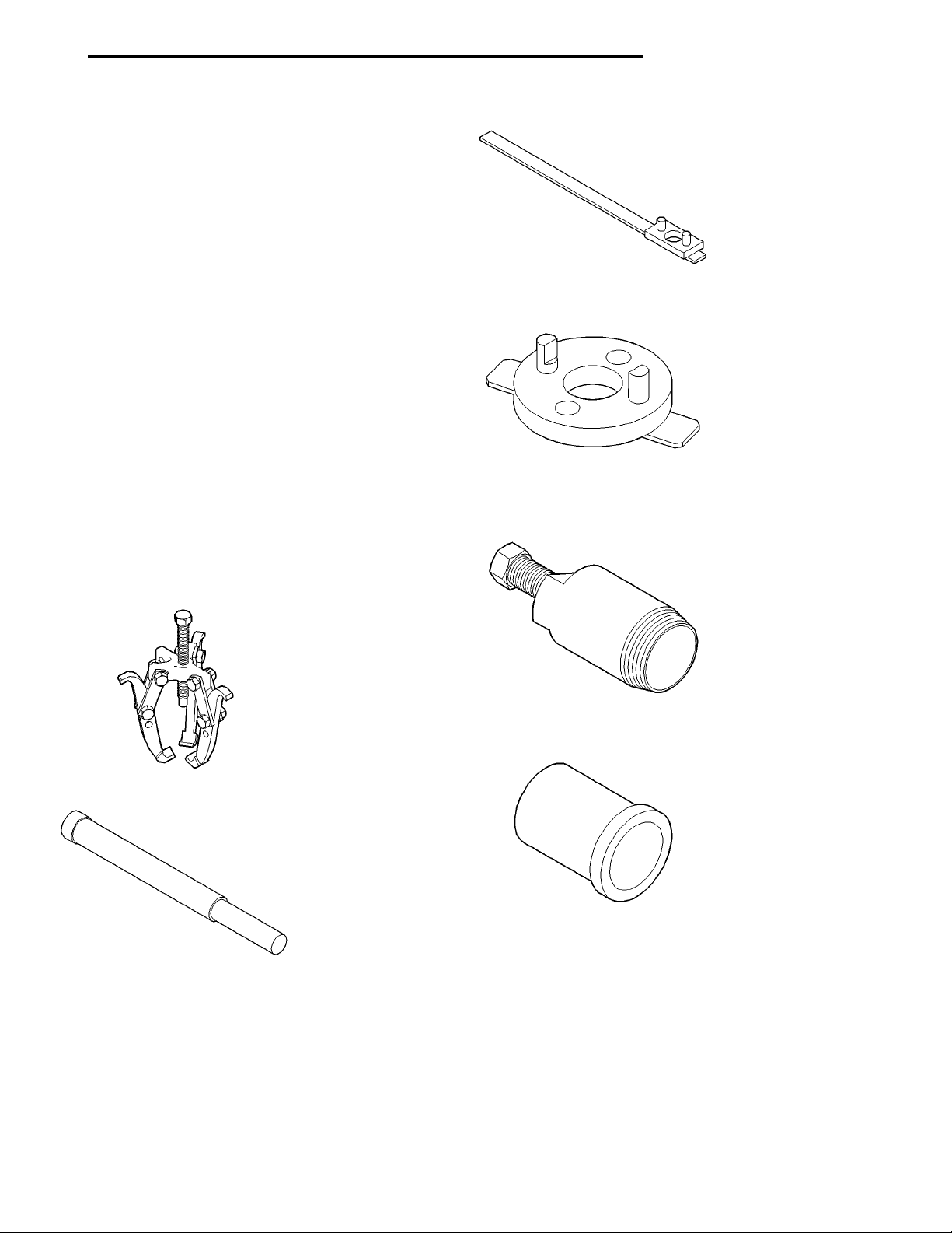
PL 2.0L SOHC ENGINE 9 - 49
SPECIFICATIONS (Continued)
DESCRIPTION ...................TORQUE
Oil Pump Cover Fastener . . . 12 N·m (105 in. lbs.)
Oil Pump Pick-up Tube Bolt . 28 N·m (250 in. lbs.)
Oil Pump Relief Valve Cap . . . 41 N·m (30 ft. lbs.)
Rear Torque Bracket
Bolts ...................110N·m(80ft.lbs.)
Rocker Arm Shaft
Bolts ...................28N·m(250 in. lbs.)
Spark Plugs ...............28N·m(20ft.lbs.)
Support Module—Front and Rear
Thru Bolt ................61N·m(45ft.lbs.)
Thermostat Housing
Bolts ...................23N·m(200 in lbs.)
Timing Belt
Tensioner ...............31N·m(275 in. lbs.)
Timing Belt Tensioner Pivot Bracket
Bolt ....................31N·m(275 in. lbs.)
Timing Belt Tensioner Pulley
Bolt .....................68N·m(50ft.lbs.)
Water Pump Mounting
Bolts ...................12N·m(105 in. lbs.)
Camshaft Sprocket Remover/Installer C-4687
Camshaft Sprocket Remover/Installer Adapter
C-4687-1
SPECIAL TOOLS
ENGINE 2.0L SOHC
Puller 1026
Crankshaft Damper Removal Insert 6827-A
Camshaft Seal Remover C-4679-A
Camshaft Seal Installer MD-998306
Page 50
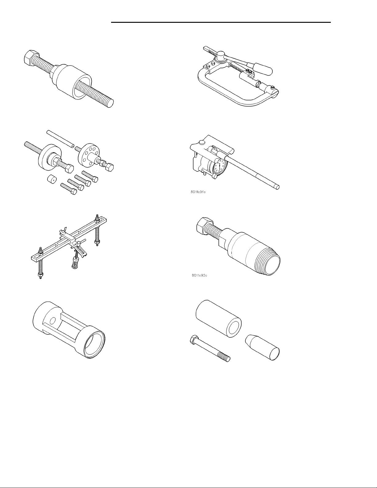
9 - 50 2.0L SOHC ENGINE PL
SPECIAL TOOLS (Continued)
Crankshaft Damper Installer 6792
Crankshaft Damper Installer C-4685-C
Valve Spring Compressor MD-998772-A
Valve Spring Compressor C-3575-A
Cylinder Bore Indicator C-119
Front Crankshaft Seal Remover 6771
Spring Compressor Adapter 6779
Front Crankshaft Seal Installer 6780
Page 51
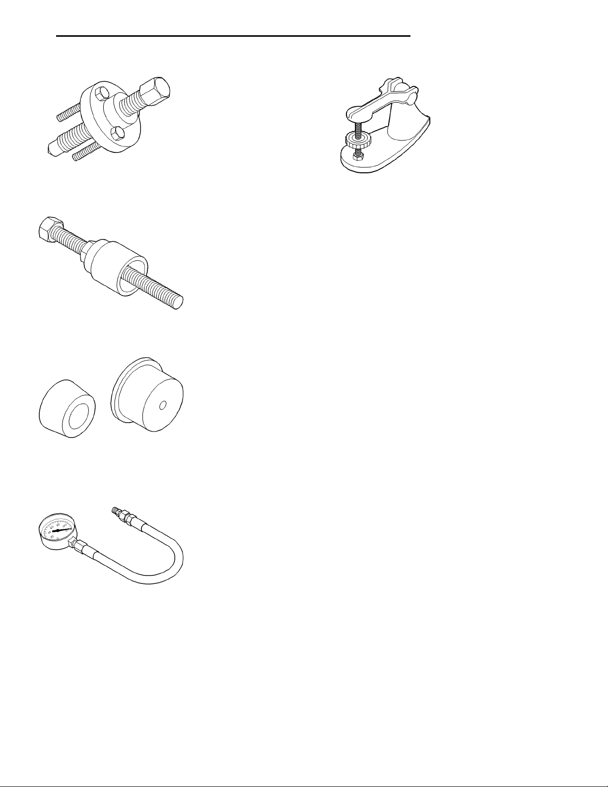
PL 2.0L SOHC ENGINE 9 - 51
SPECIAL TOOLS (Continued)
Crankshaft Sprocket Remover 6793
Crankshaft Sprocket Installer 6792
Rear Crankshaft Seal Guide and Installer 6926-1 and
6926-2
Valve Spring Tester C-647
Pressure Gage C-32932
Page 52
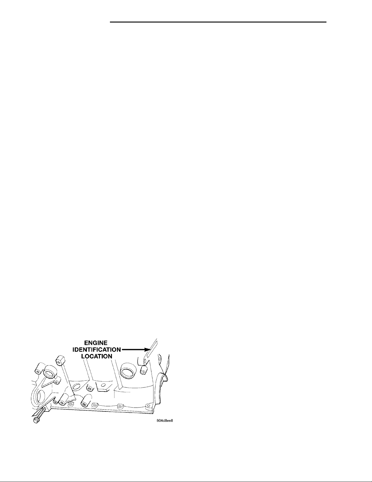
ENGINE IDENTIFICATIONLOCATION
9 - 52 2.0L DOHC ENGINE PL
2.0L DOHC ENGINE
INDEX
page page
DESCRIPTION AND OPERATION
ENGINE COMPONENTS ................. 54
ENGINE IDENTIFICATION NUMBER ........ 52
ENGINE LUBRICATION SYSTEM ........... 53
GENERAL SPECIFICATION ............... 52
DIAGNOSIS AND TESTING
CHECKING ENGINE OIL PRESSURE ........ 54
SERVICE PROCEDURES
CRANKSHAFT END PLAY ................ 56
CYLINDER BORE AND PISTON SIZING ...... 55
FITTING CONNECTING RODS ............. 56
FITTING CRANKSHAFT BEARINGS ......... 56
FITTING PISTON RINGS ................. 56
REMOVAL AND INSTALLATION
CAMSHAFT OIL SEALS .................. 71
CAM FOLLOWER AND HYDRAULIC LASH
ADJUSTER ASSEMBLY ................. 62
CAMSHAFT ........................... 61
CRANKSHAFT ......................... 75
CYLINDER HEAD COVER ................ 60
CYLINDER HEAD ....................... 63
ENGINE ASSEMBLY ..................... 59
FRONT CRANKSHAFT OIL SEAL ........... 72
FRONT MOUNT ........................ 57
LEFT MOUNT .......................... 58
OIL FILTER ADAPTER ................... 77
OILFILTER ........................... 77
OILPAN .............................. 70
OIL PUMP ............................ 77
PISTON AND CONNECTING ROD .......... 79
POWER HOP DAMPER .................. 58
REAR CRANKSHAFT SEAL ............... 73
RIGHT MOUNT ........................ 58
TIMING BELT COVER ................... 67
TIMING BELT .......................... 68
VALVE SPRING AND SEALS—CYLINDER HEAD
NOT REMOVED ...................... 63
VIBRATION DAMPER .................... 66
DISASSEMBLY AND ASSEMBLY
OIL PUMP ............................ 81
VALVE SERVICE WITH CYLINDER HEAD
REMOVED .......................... 81
CLEANING AND INSPECTION
CYLINDER BLOCK AND BORE ............ 85
CYLINDER HEAD AND CAMSHAFT
JOURNALS .......................... 84
OIL PUMP ............................ 84
SPECIFICATIONS
ENGINE 2.0L DOHC ..................... 86
TORQUE CHART 2.0L DOHC .............. 88
SPECIAL TOOLS
ENGINE 2.0L DOHC ..................... 88
DESCRIPTION AND OPERATION
ENGINE IDENTIFICATION NUMBER
The engine identification number is located on the
rear of the cylinder block (Fig. 1).
Fig. 1 Engine Identification DOHC
GENERAL SPECIFICATION
Type .............In-Line OHV, DOHC & SOHC
Bore .....................87.5mm (3.445 Inch)
Stroke ...................83.0mm (3.268 inch)
Compression Ratio ....DOHC - 9.6:1 SOHC - 9.8:1
Displacement .........2.0Liters (122 Cubic Inch)
Firing Order ........................1,3,4,2
Compression Pressure ...........1172-1551 kPa
(170 - 225 psi)
Maximum Variation
Between Cylinders ....................25%
Lubrication ...................Pressure Feed -
Full Flow Filtration
(Crankshaft Driven Pump)
Engine Oil Capacity
With Oil Filter Change .......4.25 Liter (4.5 Qts.)
Without Oil Filter Change .....3.8Liter (4.0 Qts.)
Page 53
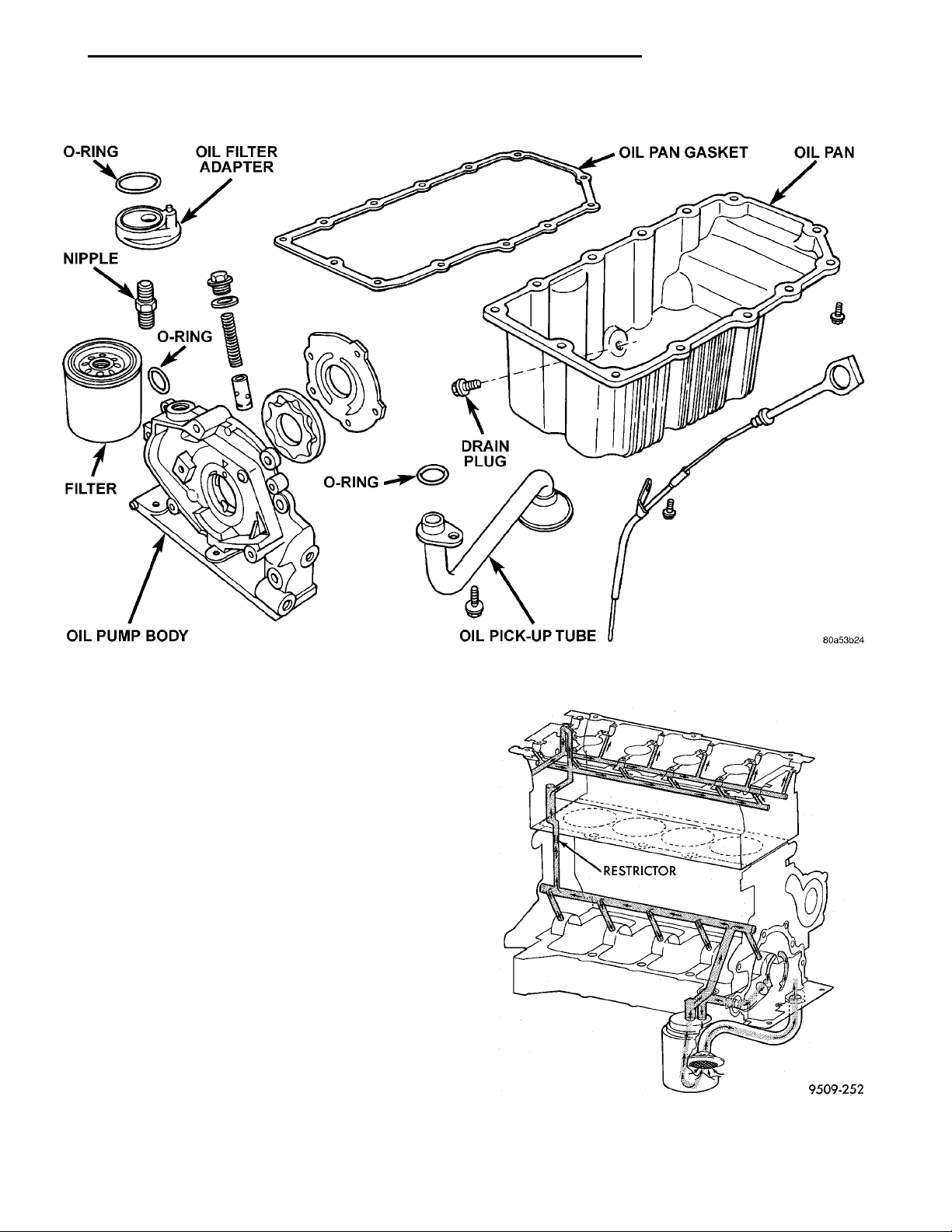
O-RINGOIL FILTER ADAPTEROIL PAN GASKETOIL PANOIL PICK-UP TUBEDRAIN PLUGO-RINGOIL PUMP BODYFILTERO-RINGNIPPLE
RESTRICTOR
PL 2.0L DOHC ENGINE 9 - 53
DESCRIPTION AND OPERATION (Continued)
ENGINE LUBRICATION SYSTEM
Fig. 2 Engine Lubrication Components
PRESSURE LUBRICATION
Oil drawn up through the pickup tube is pressurized by the pump and routed through the full flow filter (Fig. 2) to the main oil gallery running the length
of the cylinder block. A cylinder head restrictor,
located in the block, provides increased oil flow to the
main oil gallery (Fig. 3).
MAIN/ROD BEARINGS
A diagonal hole in each bulkhead feeds oil to each
main bearing. Drilled passages within the crankshaft
route oil from main bearing journals to connecting
rod journals.
CAMSHAFT/HYDRAULIC LASH ADJUSTERS
A vertical hole at the number five bulkhead routes
pressurized oil through a restrictor up past a cylinder head bolt to an oil gallery running the length of
the cylinder head. The camshaft journals are partially slotted to allow a predetermined amount of
pressurized oil to pass into the bearing cap cavities
with small holes directed to spray lubricate the camshaft lobes.
Fig. 3 Engine Lubrication System —DOHC Engine
Page 54

9 - 54 2.0L DOHC ENGINE PL
DESCRIPTION AND OPERATION (Continued)
SPLASH LUBRICATION
Oil returning to the pan from pressurized components supplies lubrication to the valve stems. Cylinder bores and wrist pins are splash lubricated from
directed slots on the connecting rod thrust collars.
ENGINE COMPONENTS
CYLINDER BLOCK AND BEDPLATE ASSEMBLY A partial open deck is used for cooling and
weight reduction with water pump molded into the
block. Nominal wall thickness is 4 mm. The bedplate
incorporates main bearing caps. Rear seal retainer is
integral with the block.
CRANKSHAFT A nodular cast iron crankshaft is
used. The engine has 5 main bearings, with number
3 flanged to control thrust. The 52 mm diameter
main and 48 mm diameter crank pin journals (all)
have undercut fillet radiuses that are deep rolled for
added strength. To optimize bearing loading 8 counterweights are used. Hydrodynamic seals provide end
sealing, where the crankshaft exits the block.
Anaerobic gasket material is used for parting line
sealing. A sintered iron timing belt sprocket is
mounted on the crankshaft nose. This sprocket provides motive power; via timing belt to the camshaft
sprocket providing timed valve actuation.
PISTONS The DOHC Engine DO NOT have provision for a free wheeling valve train. Non free
wheeling valve train means, in the event of a broken
timing belt Pistons will contact the Valves. All
engines use pressed-in piston pins to attach forged
powdered metal connecting rods. The connecting rods
are a cracked cap design and are not repairable. Hex
head cap screw are used to provide alignment and
durability in the assembly.
PISTON RINGS The piston rings include a
molybdenum faced top ring for reliable compression
sealing and a taper faced intermediate ring for additional cylinder pressure control. Oil Control Ring
Package contains of 2 steel rails and a expander
spacer.
CYLINDER HEAD Features a Dual Over Head
Camshaft (DOHC), 4 valves per cylinder cross flow
design. The valves are arranged in two inline banks,
with the ports of the bank of two intake valves per
cylinder facing toward the radiator side of engine
and ports of the bank of two exhaust valves per cylinder facing toward the dash panel. Incorporates
powder metal valve guides and seats. Integral oil galleys within the cylinder head supplies oil to the
hydraulic lash adjusters, camshaft and valve mechanisms.
CAMSHAFTS The nodular iron camshafts have
six bearing journals and 2 cam lobes per cylinder.
Flanges at the rear journals control camshaft end
play. Provision for cam position sensor is located on
the intake camshaft at the rear of cylinder head. A
hydrodynamic oil seal is used for oil control at the
front of the camshaft.
VALVES Four valves per cylinder are actuated by
roller cam followers which pivot on stationary
hydraulic lash adjusters. All valves have 6 mm diameter chrome plated valve stems. The valve sizes are
34.8 mm (1.370 inch.) diameter intake valves and
30.5 mm (1.20 inch.) diameter exhaust valves. Viton
rubber valve stem seals are integral with the spring
seats. Valve springs, spring retainers, and locks are
conventional.
INTAKE MANIFOLD The intake manifold is a
two piece aluminum casting, attached to the cylinder
head with ten fasteners. This long branch fan design
enhances low and midspeed torque.
EXHAUST MANIFOLD The exhaust manifold is
made of nodular cast iron for strength and high temperatures. Exhaust gasses exit through a machined,
articulated joint connection to the exhaust pipe.
PARTS REPLACED
If any of the following parts have been changed or
replaced:
• Camshaft
• Camshaft Position Sensor
• Camshaft Position Sensor Target Magnet
• Cylinder Block
• Cylinder Head
• Water Pump
• Powertrain Control Module (PCM)
The camshaft and crankshaft timing relearn procedure must be performed. Refer to Group 25, Emission
Control Systems for procedure.
DIAGNOSIS AND TESTING
CHECKING ENGINE OIL PRESSURE
(1) Remove oil pressure switch and install gauge
assembly C-3292 with adaptor.
(2) Run engine until thermostat opens.
CAUTION: If oil pressure is 0 at idle, Do Not perform the 3000 RPM test in the next step.
(3) Oil Pressure: Curb Idle 25 kPa (4 psi) minimum 3000 RPM 170-550 kPa (25-80 psi).
(4) If oil pressure is 0 at idle. Shut off engine,
check for pressure relief valve stuck open, a clogged
oil pick-up screen or a damaged oil pick-up tube
O-ring.
Page 55
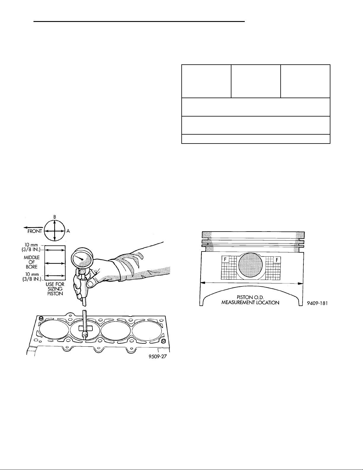
FRONT MIDDLEOF BORE
USE FOR
SIZING
PISTON
PL 2.0L DOHC ENGINE 9 - 55
SERVICE PROCEDURES
CYLINDER BORE AND PISTON SIZING
The cylinder walls should be checked for out-ofround and taper with Tool C-119 (Fig. 4). The cylinder bore out-of-round is 0.050 mm (.002 inch)
maximum and cylinder bore taper is 0.051 mm (0.002
inch) maximum. If the cylinder walls are badly
scuffed or scored, the cylinder block should be
rebored and honed, and new pistons and rings fitted.
Whatever type of boring equipment is used, boring
and honing operation should be closely coordinated
with the fitting of pistons and rings in order that
specified clearances may be maintained. Refer to
Honing Cylinder Bores outlined in the Standard Service Procedures for specification and
procedures.
Measure the cylinder bore at three levels in directions A and B (Fig. 4). Top measurement should be
10 mm (3/8 inch) down and bottom measurement
should be 10 mm (3/8 inch.) up from bottom of bore.
Refer to Cylinder Bore and Piston Specifications
Table.
CYLINDER BORE AND PISTON
SPECIFICATIONS TABLE
Standard Bore Maximum
PISTON O.D. MEASURE-MENT LOCATION
Out-of-Round
87.5 mm (3.445
in.)
0.051 mm
(0.002 in.)
Maximum
Taper
0.051 mm
(0.002 in.)
Standard Piston Size
87.457 - 87.475 mm (3.4432 - 3.4439 in.)
Piston to Bore Clearance
0.018 - 0.050 mm (0.0007 - 0.0020 in.)
Measurements Taken at Piston Size Location
SIZING PISTONS
Piston and cylinder wall must be clean and dry.
Piston diameter should be measured 90 degrees to
piston pin about 17.5 mm (11/16 inch) from the bottom of the skirt as shown in (Fig. 5). Cylinder bores
should be measured halfway down the cylinder bore
and transverse to the engine crankshaft center line
shown in (Fig. 4). Refer to Cylinder Bore and Piston
Specifications Table. Correct piston to bore clearance
must be established in order to assure quiet and economical operation.
Fig. 4 Checking Cylinder Bore Size
Fig. 5 Piston Measurements
Chrysler engines use pistons designed specifically
for each engine model. Clearance and sizing locations
vary with respect to engine model.
NOTE: Pistons and cylinder bores should be measured at normal room temperature, 21°C (70°F).
Page 56
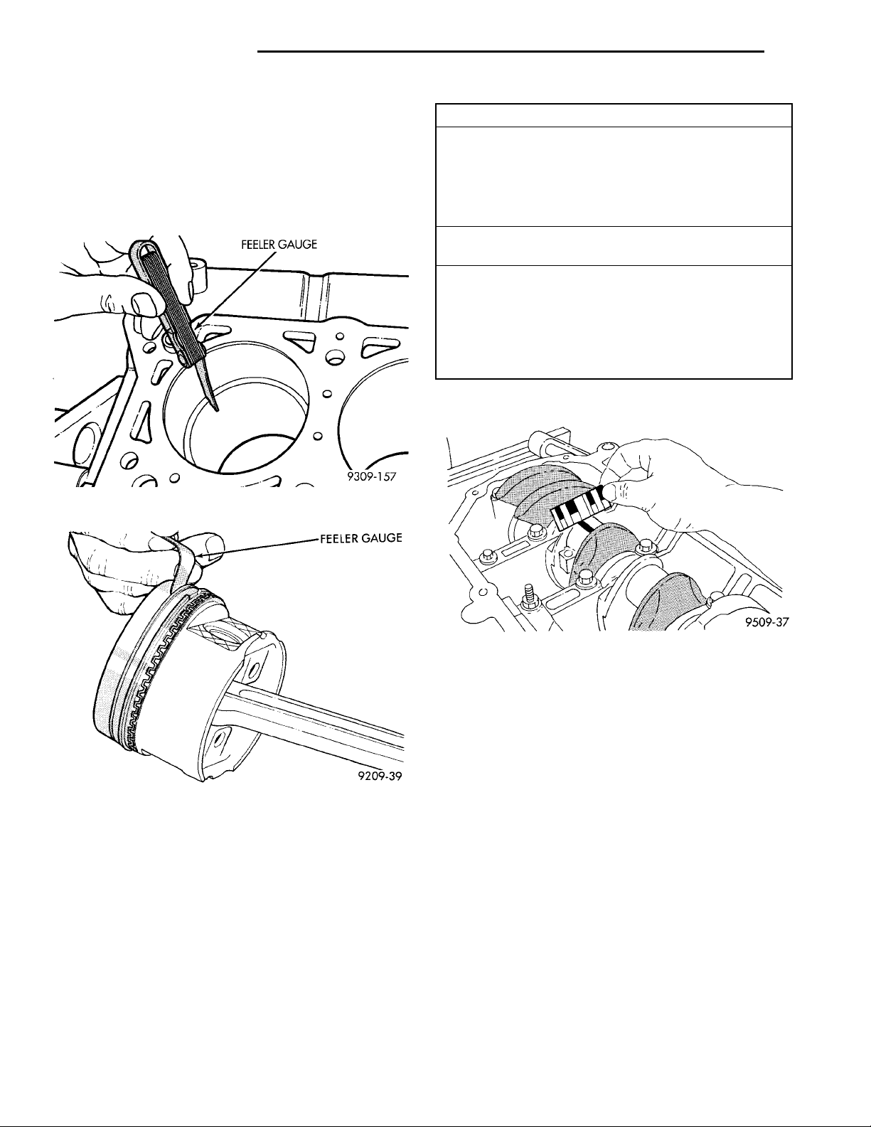
FEELER GAUGE
FEELER GAUGE
9 - 56 2.0L DOHC ENGINE PL
SERVICE PROCEDURES (Continued)
FITTING PISTON RINGS
(1) Wipe cylinder bore clean. Insert ring and push
down with piston to ensure it is square in bore. The
ring gap measurement must be made with the ring
positioning at least 12 mm (0.50 inch) from bottom of
cylinder bore. Check gap with feeler gauge (Fig. 5).
Refer to specifications (Fig. 7).
Fig. 6 Piston Ring Gap
Ring Position Ring Gap Wear Limit
Upper Ring 0.23 to 0.52 mm
Intermediate
Ring
Oil Control
Ring
Ring Position Groove Clearance Maximum
Upper Ring 0.025 to 0.065 mm
Intermediate
Ring
OIL CONTROL RING - THREE PIECE. OIL RING SIDE
RAILS MUST BE FREE TO ROTATE AFTER
ASSEMBLY.
(0.009 to 0.020 in.)
0.49 to 0.78 mm
(0.019 to 0.031 in.)
0.23 to 0.66 mm
(0.009 to 0.026 in.)
(0.0010 to 0.0026 in.)
0.025 to 0.065 mm
(0.0010 to 0.0026 in.)
0.8 mm
(0.031 in.)
1.0 mm
(0.039 in.)
1.0 mm
(0.039 in.)
Clearance
0.10 mm
(0.004 in.)
0.10 mm
(0.004 in.)
Fig. 8 Piston Ring Specifications
Fig. 7 Piston Ring Side Clearance
(2) Check piston ring to groove side clearance (Fig.
6). Refer to specification (Fig. 7).
FITTING CONNECTING RODS
(1) Follow the procedure specified in the Standard
Service Procedures Section for Measuring Main Bearing Clearance and Connecting Rod Bearing Clearance (Fig. 8). Refer to specifications.
CAUTION: Do not rotate crankshaft or the Plastigage may be smeared.
NOTE: The rod bearing bolts should not be reused.
Fig. 9 Checking Connecting Rod Bearing Clearance
(2) Before installing the NEW bolts the threads
should be oiled with clean engine oil.
(3) Install each bolt finger tight than alternately
torque each bolt to assemble the cap properly.
(4) Tighten the bolts to 27 N·m PLUS 1/4 turn (20
ft. lbs. PLUS 1/4 turn) Do not use a torque
wrench for last step.
(5) Using a feeler gauge, check connecting rod side
clearance (Fig. 9). Refer to connecting rod specifications (Fig. 10).
FITTING CRANKSHAFT BEARINGS
Refer to Measuring Main Bearing Clearance in
Standard Service Procedures. Refer to (Fig. 11) for
specifications.
CRANKSHAFT END PLAY
DIAL INDICATOR METHOD
(1) Mount a dial indicator to front of engine, locating probe on nose of crankshaft (Fig. 12).
(2) Move crankshaft all the way to the rear of its
travel.
Page 57
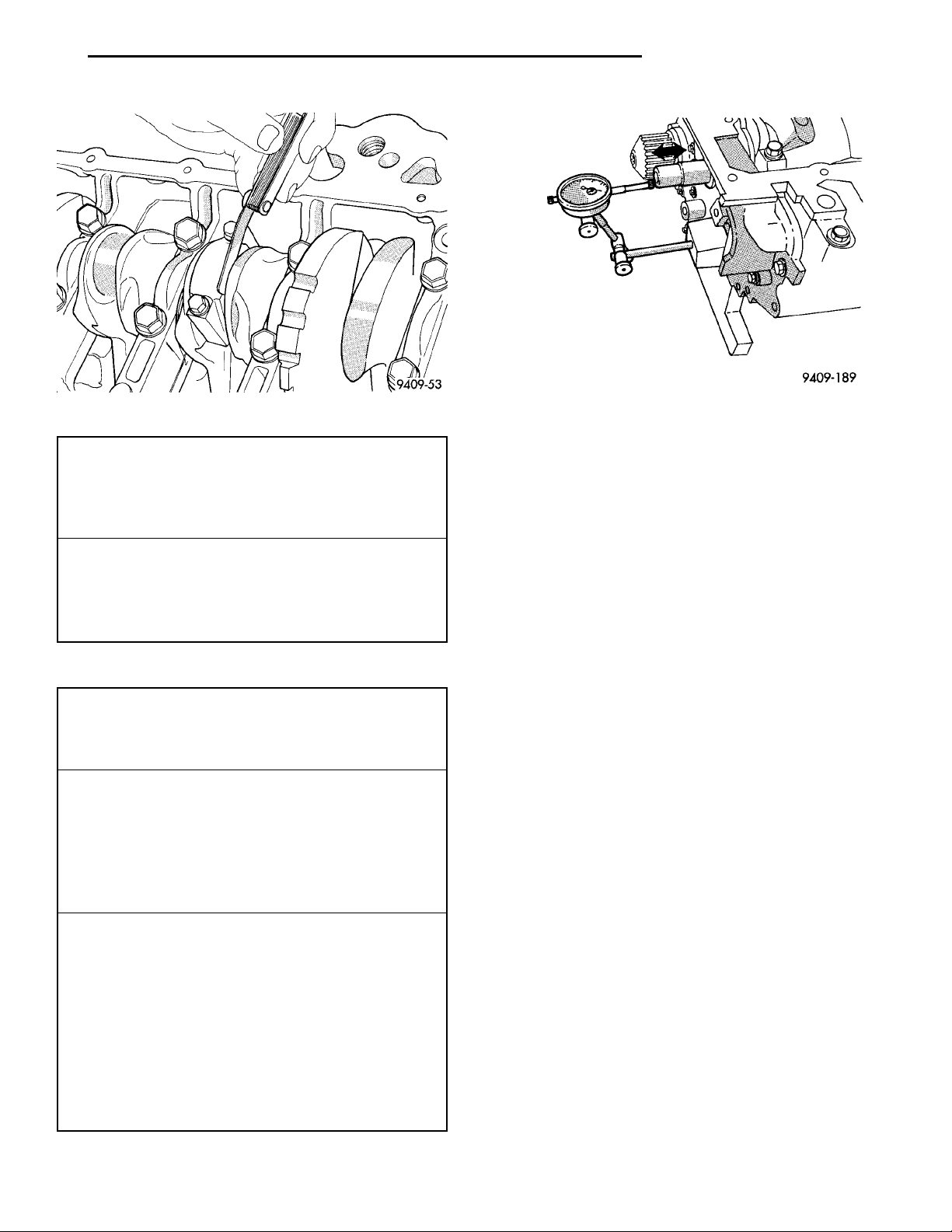
PL 2.0L DOHC ENGINE 9 - 57
SERVICE PROCEDURES (Continued)
Fig. 10 Checking Connecting Rod Side Clearance
CONNECTING ROD BEARING OIL CLEARANCE
New Part: 0.026 to 0.059 mm
(0.001 to 0.0023 in.)
Wear Limit: 0.075 mm
(0.003 in.)
CONNECTING ROD SIDE CLEARANCE
New Part: 0.13 to 0.38 mm
(0.005 to 0.015 in.)
Wear Limit: 0.40 mm
(0.016 in.)
Fig. 11 Connecting Rod Specifications
Crankshaft End-Play
New Part: 0.09 - 0.24 mm (0.0035 -
0.0094 in.)
Wear Limit: 0.37 mm (0.015 in.)
Main Bearing Clearance
New Part: .022 - .062 mm
(0.0008 - 0.0024 in.)
Connecting Rod Bearing Clearance
New Part: 0.026 - .059 mm
(0.001 - 0.0023 in.)
Wear Limit: 0.075 mm (0.003 in.)
Crankshaft Journal Sizes
Main Bearing Journal Diameter
Standard 52.000 6 0.008 mm
(2.0472 6 0.0003 in.)
1st Undersize 51.983 6 0.008 mm
(2.0466 6 0.0003 in.)
Connecting Rod Journal
Standard 48.000 6 0.008 mm
(1.8897 6 0.0003 in.)
1st Undersize 47.983 6 0.008 mm
(1.8891 6 0.0003 in.)
Fig. 12 Crankshaft Specifications
Fig. 13 Checking Crankshaft End Play— Dial
Indicator
(3) Zero the dial indicator.
(4) Move crankshaft all the way to the front and
read the dial indicator. Refer to (Fig. 11) for specifications.
FEELER GAGE METHOD
(1) Move crankshaft all the way to the rear of its
travel using a lever inserted between a main bearing
cap and a crankshaft cheek, using care not to damage any bearing surface. Do not loosen main bearing
cap.
(2) Use a feeler gauge between number three
thrust bearing and machined crankshaft surface to
determine end play.
REMOVAL AND INSTALLATION
FRONT MOUNT
(1) Raise vehicle on hoist.
(2) Support the engine and transmission assembly
with a floor jack so it will not rotate.
(3) Remove the front engine mount thru-bolt from
the insulator and engine mount bracket (Fig. 14).
(4) Remove the mass damper. Remove the front
mount nuts and remove insulator assembly.
(5) Remove the engine mount bracket, if necessary.
(6) Reverse removal procedure for installation and
tighten fasteners in this order.
a. If engine mount bracket was removed, tighten
bolt 1 to 3 N·m (20 in. lbs.) and bolts 2, 3 and 4 to
108 N·m (80 ft. lbs.) (Fig. 14).
b. If engine mount bracket was removed, tighten
bolts 5 and 1 to 54 N·m (40 ft. lbs.).
c. Tighten engine mount bracket to insulator
assembly thru-bolt to 54 N·m (40 ft. lbs.).
d. Tighten insulator assembly nuts to the lower
radiator crossmember torque to 54 N·m (40 ft. lbs.).
Page 58
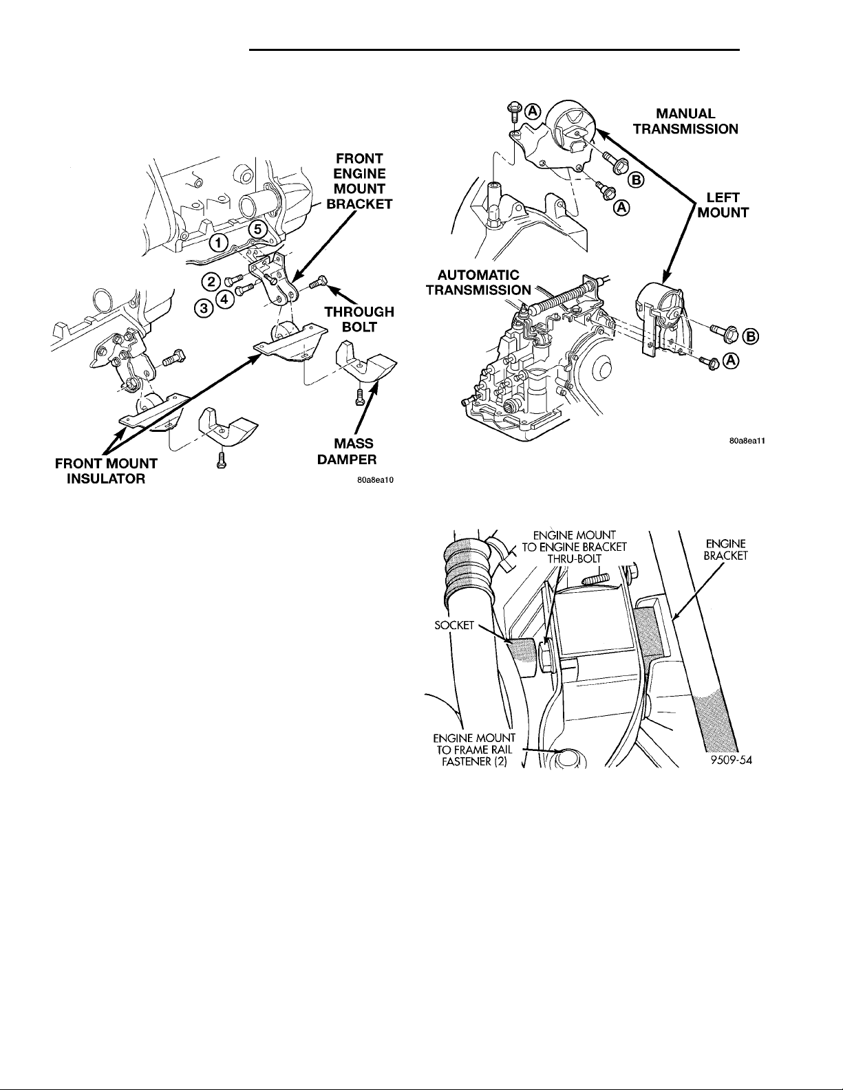
MANUAL TRANSMISSIONLEFT MOUNTAUTOMATIC TRANSMISSION
9 - 58 2.0L DOHC ENGINE PL
REMOVAL AND INSTALLATION (Continued)
e. Install mass damper and tighten to 54 N·m (40
ft. lbs.)
Fig. 14 Engine Mounting—Front
LEFT MOUNT
(1) Raise vehicle on hoist and remove left front
wheel.
(2) Remove the Power Distribution Center (PDC)
on manual transaxle model, from battery tray mount
and lay aside.
(3) Support the transmission with a transmission
jack.
(4) Remove the thru-bolt access hole cover. Remove
the insulator thru-bolt from the mount (Fig. 15).
(5) Remove the transmission mount fasteners and
remove mount.
(6) Reverse removal procedure for installation.
Tighten fasteners in this order (Fig. 15):
A. 55 N·m (40 ft. lbs.)
B. 108 N·m (80 ft. lbs.)
RIGHT MOUNT
(1) Remove the purge duty solenoid from engine
mount bracket.
(2) Remove the right engine mount insulator vertical fasteners from frame rail (Fig. 16).
(3) Remove the load on the engine mounts by carefully supporting the engine and transmission assembly with a floor jack.
(4) Remove the thru-bolt access hole cover. Remove
the thru-bolt from the insulator assembly (Fig. 16).
Remove insulator.
(5) Reverse removal procedure for installation.
Tighten engine mount to rail fasteners to 54 N·m (40
Fig. 15 Engine Mounting—Left
ft. lbs.), then tighten engine mount to engine bracket
thru-bolt to 108 N·m (80 ft. lbs.).
Fig. 16 Engine Mounting—Right
POWER HOP DAMPER
NOTE: Power hop damper is used on manual transmission vehicle only.
(1) Remove the thru-bolt and nut from the front
suspension crossmember (Fig. 17).
(2) Remove the damper nut and grommets.
Remove the damper.
(3) Remove the power hop damper bracket, if nec-
essary.
(4) Reverse removal procedure for installation.
Tighten all bolts and nuts to 54 N·m (40 ft. lbs.)
Page 59
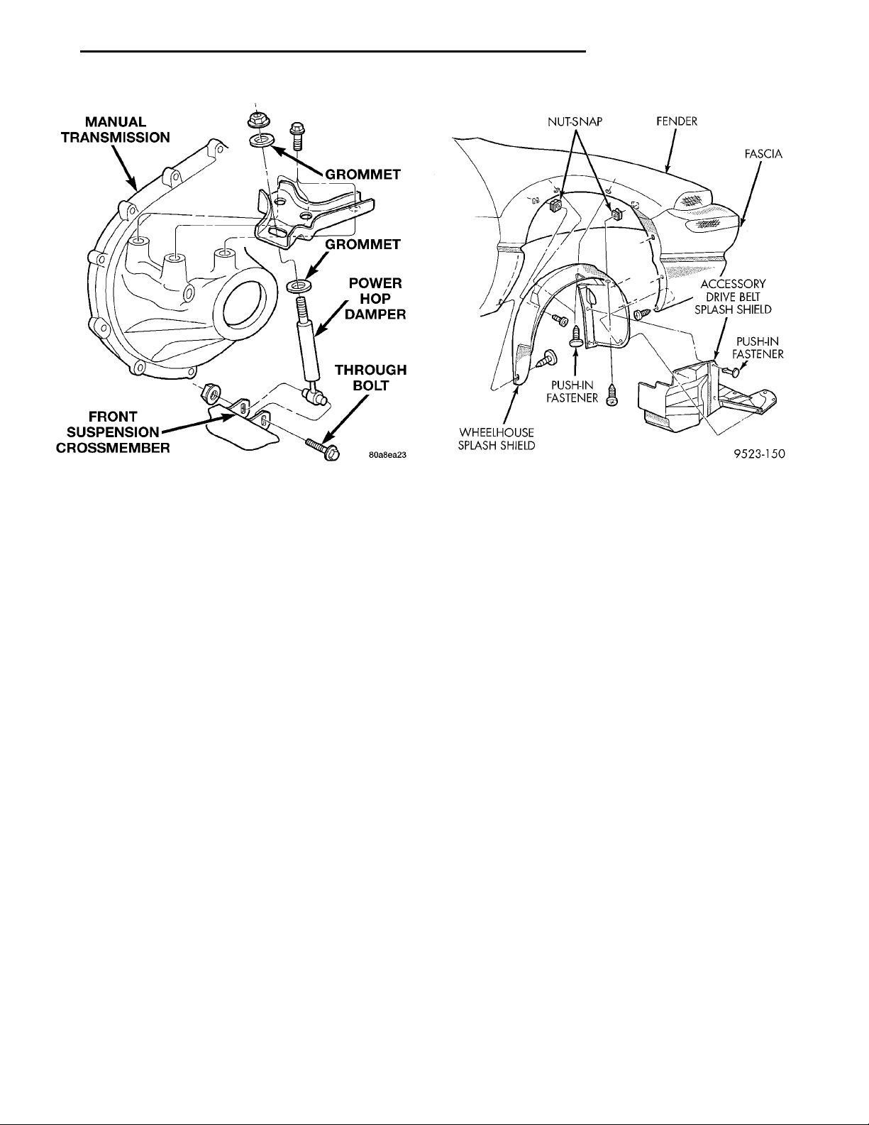
PL 2.0L DOHC ENGINE 9 - 59
REMOVAL AND INSTALLATION (Continued)
Fig. 17 Power Hop Damper
ENGINE ASSEMBLY
REMOVAL
(1) Perform fuel pressure release procedure. Refer
to Group 14, Fuel System for procedure. Remove fuel
line to fuel rail.
(2) Disconnect and remove battery and tray. Set
Powertrain Control Module (PCM) aside.
(3) Drain cooling system. Refer to Group 7, Cooling
System for procedure.
(4) Remove upper radiator hose, radiator and fan
module. Refer to Group 7, Cooling System for procedure.
(5) Remove lower radiator hose.
(6) Disconnect automatic transmission cooler lines
and plug. If equipped.
(7) Disconnect clutch cable (Manual) and transmission shift linkage.
(8) Disconnect throttle body linkage.
(9) Disconnect engine wiring harness.
(10) Disconnect heater hoses.
(11) Discharge Air Conditioning System. Refer to
Group 24, Air Conditioning for procedure.
(12) Hoist vehicle and remove right inner splash
shield (Fig. 17).
(13) Remove accessory drive belts. Refer to Group
7, Cooling System for procedure.
(14) Remove axle shafts. Refer to Group 2, Suspension and Driveshafts for procedure.
(15) Disconnect exhaust pipe from manifold.
(16) Remove front engine mount.
(17) Manual transmission: Remove power hop
damper.
Fig. 18 Right Inner Splash Shield
(18) Lower vehicle. Remove air cleaner assembly.
(19) Remove power steering pump and reservoir,
Set them aside.
(20) Remove A/C compressor.
(21) Remove ground straps to body.
(22) Raise vehicle enough to allow engine dolly
and cradle Special Tools 6135 and 6710 to be
installed under vehicle.
(23) Loosen engine support posts to allow movement for positioning onto engine locating holes and
flange on the engine bedplate. Lower vehicle and
position cradle until the engine is resting on support
posts (Fig. 18). Tighten mounts to cradle frame. This
will keep support posts from moving when removing
or installing engine and transmission.
(24) Install safety straps around the engine to cradle tighten; straps and lock them into position.
(25) Raise vehicle enough to see if straps are tight
enough to hold cradle assembly to engine.
(26) Lower vehicle so weight of the engine and
transmission ONLY is on the cradle assembly.
(27) Remove engine and transmission mount thrubolts.
(28) Raise vehicle slowly. It may be necessary to
move the engine/transmission assembly with the cradle to allow for removal around body flanges.
INSTALLATION
(1) Position engine and transmission assembly
under vehicle and slowly lower the vehicle over the
engine and transmission.
(2) Align engine and transmission mounts to
attaching points. Install mounting bolts at the right
Page 60
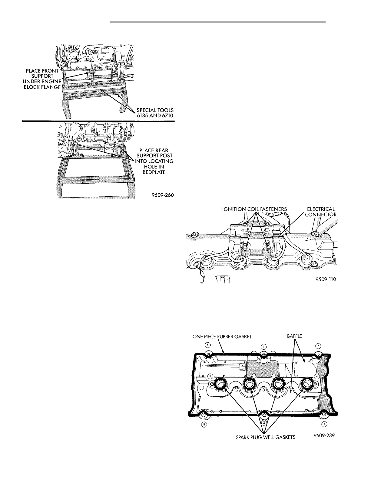
9 - 60 2.0L DOHC ENGINE PL
REMOVAL AND INSTALLATION (Continued)
(15) Connect fuel line and heater hoses.
(16) Install ground straps. Connect engine and
throttle body connections and harnesses. Refer to
Group 8, Electrical for procedure.
(17) Connect throttle body linkage. Refer to Group
14, Fuel System for procedure.
(18) Install radiator and shroud assembly. Install
radiator hoses. Fill cooling system. Refer to Group 7,
Cooling System for filling procedure.
(19) Install battery tray and battery. Set Powertrain Control Module (PCM) into place.
(20) Install air cleaner and hoses.
(21) Install oil filter. Fill engine crankcase with
proper oil to correct level.
(22) Start engine and run until operating temperature is reached.
(23) Adjust transmission linkage, if necessary.
ONE PIECE RUBBER GASKET
CYLINDER HEAD COVER
IGNITION COIL FAS-
TENERS
REMOVAL
(1) Remove ignition coil pack (Fig. 20).
ELECTRICALCONNECTOR
BAFFLESPARK PLUG WELL GASKETS
Fig. 19 Positioning Engine Cradle Support Post
Mounts
engine and left transmission mounts. Refer to procedures outlined in this section.
(3) Remove safety straps from engine and transmission assembly. Slowly raise vehicle enough to
remove the engine dolly and cradle.
(4) Install axle shafts. Refer to Group 2, Suspension and Driveshafts for procedure.
(5) Install transmission and engine braces and
splash shields.
(6) Connect exhaust system to manifold. Refer to
Group 11, Exhaust System and Intake Manifold for
procedure and torque specifications.
(7) Install power steering pump and reservoir.
Refer to Group 7, Cooling System Accessory Drive
Section for belt tension adjustment.
(8) Install A/C compressor and hoses. Refer to
Group 24, Heater and Air Conditioning for procedure.
(9) Install accessory drive belts. Refer to Group 7,
Cooling System Accessory Drive Section for belt tension adjustment.
(10) Install front engine mount. Refer to this section for procedure.
(11) Manual transmission: Install power hop
damper.
(12) Install inner splash shield. Install wheels and
tires.
(13) Manual Transmission: Connect clutch cable
and linkages. Refer to Group 6, Manual Transaxle
Clutch.
(14) Automatic Transmission: Connect shifter
and kickdown linkage. Refer to Group 21, Transaxle
for procedures.
Fig. 20 Ignition Coil Pack
(2) Remove the cylinder head cover fasteners (Fig.
21).
(3) Remove cylinder head cover from cylinder
head.
Fig. 21 Cylinder Head Cover and Gasket
Page 61
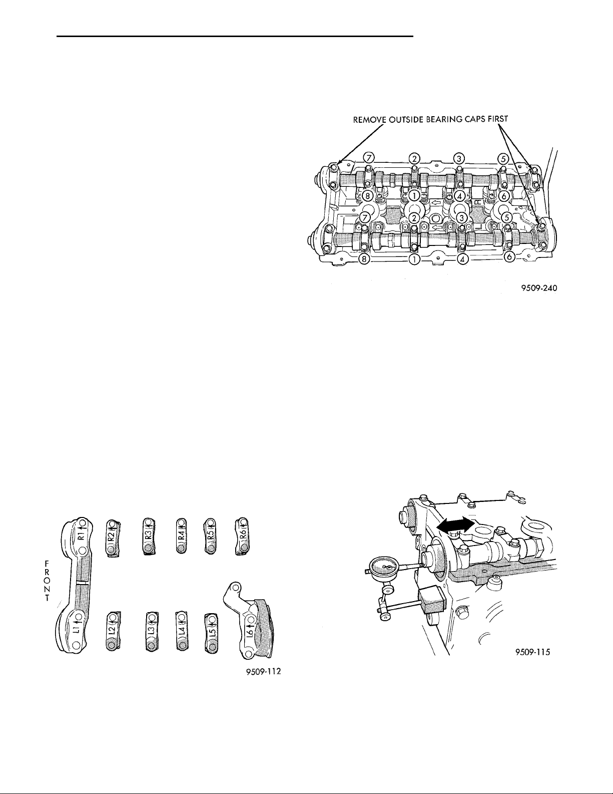
PL 2.0L DOHC ENGINE 9 - 61
REMOVAL AND INSTALLATION (Continued)
COVER INSTALLATION
NOTE: Before installation, clean cylinder head and
cover mating surfaces. Make certain the rails are
flat.
(1) Install new cylinder head cover gaskets.
CAUTION: Do not allow oil or solvents to contact
the timing belt as they can deteriorate the rubber
and cause tooth skipping.
(2) Apply Mopar Silicone Rubber Adhesive Sealant
at the camshaft cap corners and at the top edges of
the 1/2 round seal.
(3) Install cylinder head cover assembly to head
and tighten fasteners in sequence shown in (Fig. 21).
FR0NT
Using the 3 step torque method:
• Step 1 Tighten all fasteners to 4.5 N·m (40 in.
lbs.)
• Step 2 Tighten all fasteners to 9.0 N·m (80 in.
lbs.)
• Step 3 Tighten all fasteners to 12 N·m (105 in.
lbs.)
(4) Install ignition coil pack. Tighten fasteners to
12 N·m (105 in. lbs.).
CAMSHAFT
REMOVAL
(1) Remove valve cover using procedure outlined in
this section.
(2) Remove timing belt, sprockets and covers.
Refer to Timing Belt Service outlined in this section.
(3) Bearing caps are identified for location.
Remove the outside bearing caps first (Fig. 22).
CAUTION: Camshafts are not interchangeable. The
intake cam number 6 thrust bearing face spacing is
wider.
Fig. 23 Camshaft Bearing Cap— Removal
(5) Identify the camshafts before removing from
the head. The camshafts are not interchangeable.
CAMSHAFT END PLAY
(1) Oil camshaft journals and install camshaft
WITHOUT cam follower assemblies. Install rear cam
caps and tighten screws to specified torque.
(2) Using a suitable tool, move camshaft as far
rearward as it will go.
(3) Zero dial indicator (Fig. 24).
(4) Move camshaft as far forward as it will go.
(5) End play travel: 0.05– 0.15 mm (0.002– 0.06
in.).
Fig. 22 Camshaft Bearing Cap Identification
(4) Loosen the camshaft bearing cap attaching fasteners in sequence shown in (Fig. 23) one camshaft
at a time.
Fig. 24 Camshaft End Play
Page 62
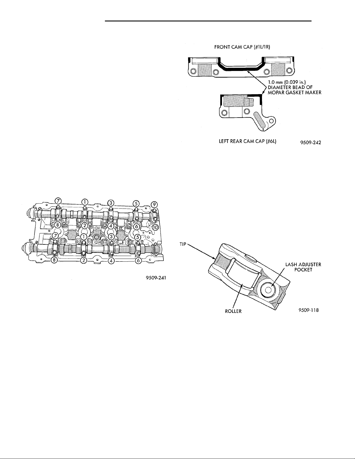
9 - 62 2.0L DOHC ENGINE PL
REMOVAL AND INSTALLATION (Continued)
INSTALLATION
NOTE: Check camshaft for binding in cylinder
head. Inspect camshaft bearing journals for damage. If camshafts are binding, also check the cylinder head bearing surface for damage, and check
the camshaft bearing oil feed holes in the cylinder
head for clogging.
Check the cam surface for abnormal wear and
damage, replace if defective. A visible worn groove
in the roller follower or on the cam lobes is cause
for replacement.
CAUTION: Ensure that NONE of the pistons are at
top dead center when installing the camshafts.
(1) Lubricate bearing journals and cam followers
with clean oil and install the camshafts. Install right
and left camshaft bearing caps #2 thru #5 and right
#6. Tighten M6 fasteners to 12 N·m (105 in. lbs.) in
sequence shown in (Fig. 25).
Fig. 25 Camshaft Bearing Cap—Tightening
Sequence
(2) Apply Mopar Gasket Maker to No. 1 and No. 6
bearing caps (Fig. 26). Install bearing caps and
tighten M8 fasteners to 24 N·m (215 in. lbs.).
(3) Bearing cap number 1, must be installed before
the camshaft seals can be installed.
(4) Install timing belt, sprockets and covers. Refer
to timing belt service outlined in this section.
(5) Install valve cover using procedure outlined in
this section.
CAM FOLLOWER AND HYDRAULIC LASH ADJUSTER ASSEMBLY
REMOVAL
(1) Remove valve cover using procedure outlined in
this section.
(2) Remove timing belt, sprockets and covers using
procedure outlined in this section.
Fig. 26 Camshaft Bearing Cap Sealing
(3) Remove camshaft. Refer to procedure previ-
ously outline this section.
(4) Remove cam follower assemblies from cylinder
head. Keep the cam followers in the order they have
TIP LASH ADJUSTERPOCKETROLLER
been removed from the head for reassembly.Mark
hydraulic lash adjusters for reassembly in their original position. Lash adjusters are serviced as a assembly.
NOTE: Inspect the cam follower assembly for wear
or damage (Fig. 27). Replace as necessary.
Fig. 27 Cam Follower Assembly
INSTALLATION
(1) Install hydraulic lash adjuster assembly making sure that adjusters are at least partially full of
oil. This is indicated by little or no plunger travel
when the lash adjuster is Lubricate with clean oil
and install cam follower assemblies in their original
position on the hydraulic adjuster and valve stem
(Fig. 28).
(2) Install the camshafts. Refer to procedure previously outlined in this section.
HYDRAULIC LASH ADJUSTER NOISE
A tappet like noise may be produced from several
items. Refer to Lash Adjuster Noise Diagnosis in
Standard Service Procedures, outlined in this Group.
Page 63
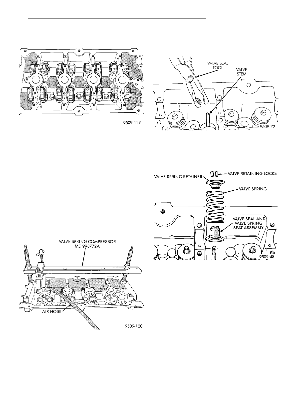
VALVE SPRING COMPRES-SOR MD 998772AAIR HOSE
VALVE SEAL TOOL VALVE STEM
VALVE RETAINING LOCKSVALVESPRINGVALVE SEAL ANDVALVE SPRING SEATASSEMBLYVALVE SPRINGRETAINER
PL 2.0L DOHC ENGINE 9 - 63
REMOVAL AND INSTALLATION (Continued)
(5) Remove valve spring.
(6) Remove valve stem seal by using a valve stem
seal tool (Fig. 30).
Fig. 28 Cam Follower Assemblies—Installation
Hydraulic Lash adjusters are replaced as an
assembly and are not repaired.
VALVE SPRING AND SEALS—CYLINDER HEAD NOT REMOVED
REMOVAL
(1) Remove camshafts as previously outlined in
this section.
(2) Rotate crankshaft until piston is at TDC on
compression.
(3) With air hose attached to adapter tool installed
in spark plug hole, apply 90 - 120 psi air pressure.
(4) Using Special Tool MD998772A with adapter
6779 (Fig. 29) compress valve springs and remove
valve locks.
Fig. 29 Removing and Installing Valve Spring
Fig. 30 Valve Stem Oil Seal Tool
INSTALLATION
(1) Install valve seal/valve spring seat assembly
(Fig. 31) as outlined in the valve installation procedure in this section.
Fig. 31 Valve Stem Seal and Valve Spring Seat
Assemblies
(2) Install valve spring and retainer. Using Special
Tool MD998772A compress valve springs only enough
to install locks. Correct alignment of tool is necessary
to avoid nicking valve stems (air pressure required),
piston at TDC.
(3) Remove air hose and install spark plugs.
(4) Install camshafts as previously outlined in this
section.
(5) Install valve cover as previously outlined in
this section.
CYLINDER HEAD
Cylinder Head and Valve Assembly
Page 64
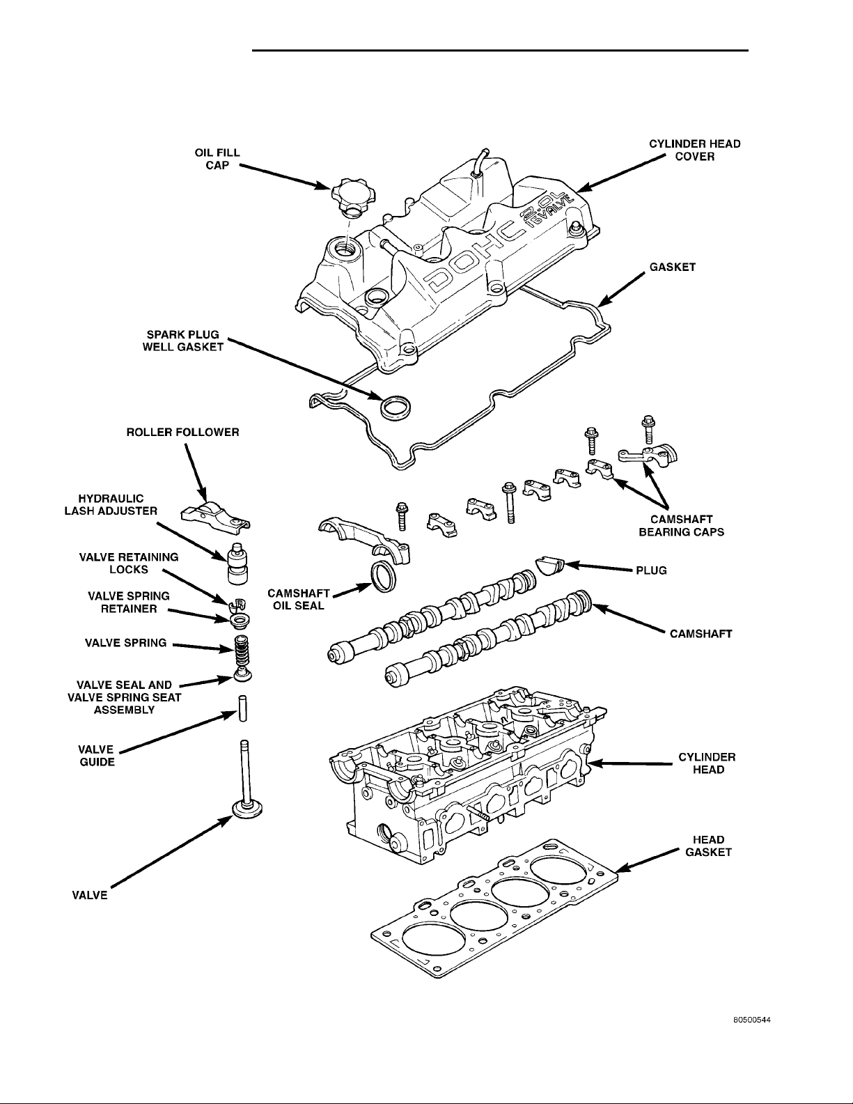
OIL FILL CAP CYLINDER HEAD COVERGASKETCAMSHAFT BEARING CAPSPLUG CAMSHAFTCYLINDER HEADHEAD GASKETVALVEVALVE GUIDEVALVE SEAL AND VALVESPRING SEAT ASSEMBLYVALVE SPRINGVALVE SPRING RETAINERVALVE RETAINING LOCKSHYDRAULIC LASHADJUSTERROLLER FOLLOWERSPARK PLUG WELL GASKET CAMSHAFT OIL SEAL
9 - 64 2.0L DOHC ENGINE PL
REMOVAL AND INSTALLATION (Continued)
Page 65
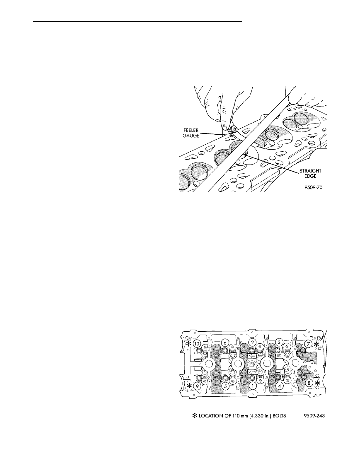
PL 2.0L DOHC ENGINE 9 - 65
REMOVAL AND INSTALLATION (Continued)
REMOVAL
(1) Perform fuel system pressure release procedure
before attempting any repairs. Refer to Group 14,
Fuel System.
(2) Disconnect negative battery cable. Drain cooling system. Refer to Group 7, Cooling System.
(3) Remove air cleaner duct and air cleaner, disconnect all vacuum lines, electrical wiring and fuel
line from fuel rail and throttle body.
(4) Remove throttle linkage.
(5) Remove accessory drive belts. Refer to Group 7,
Cooling System for procedure.
(6) Remove power brake vacuum hose from intake
manifold.
(7) Raise vehicle and remove exhaust pipe from
manifold.
(8) Remove power steering pump assembly and set
aside.
(9) Disconnect coil pack wiring connector and
remove coil pack from engine.
(10) Remove cam sensor and fuel injectors wiring
connectors.
(11) Remove timing belt and camshaft sprocket.
Refer to procedure outlined in this section.
(12) Remove cylinder head cover.
(13) Remove camshaft and cam follower assemblies. Refer to Camshaft Service for removal procedure outlined in this section.
(14) Remove cylinder head bolts.
NOTE: Remove all gasket material from cylinder
head and block. Be careful not to gouge or scratch
the aluminum head sealing surface.
CYLINDER HEAD FLATNESS
FEELERGAUGE STRAIGHTEDGE
(1) Cylinder head must be flat within 0.1 mm
(0.004 inch) (Fig. 32).
NOTE: Inspect camshaft bearing journals for scoring.
LOCATION OF 110 mm (4.330 in.) BOLTS
Fig. 32 Checking Cylinder Head Flatness
INSTALLATION
(1) Before installing the bolts the threads should
be oiled with engine oil. The 4 short bolts 110 mm
(4.330 in.) are to be installed in positions 7, 8, 9, and
10 (Fig. 33).
(2) Tighten the cylinder head bolts in this
sequence shown in (Fig. 33). Follow the four step procedure listed below.
• First Bolts 1 thru 6 to 34 N·m (25 ft. lbs.) and
Bolts 7 thru 10 to 28 N·m (20 ft. lbs.)
• Second Bolts 1 thru 6 to 68 N·m (50 ft. lbs.) and
Bolts 7 thru 10 to 28 N·m (20 ft. lbs.)
• Third Bolts 1 thru 6 to 68 N·m (50 ft. lbs.) and
Bolts 7 thru 10 to 28 N·m (20 ft. lbs.)
• Fourth Turn an additional 1/4 Turn, Do not use
a torque wrench for this step.
Fig. 33 Cylinder Head Tightening Sequence
Page 66
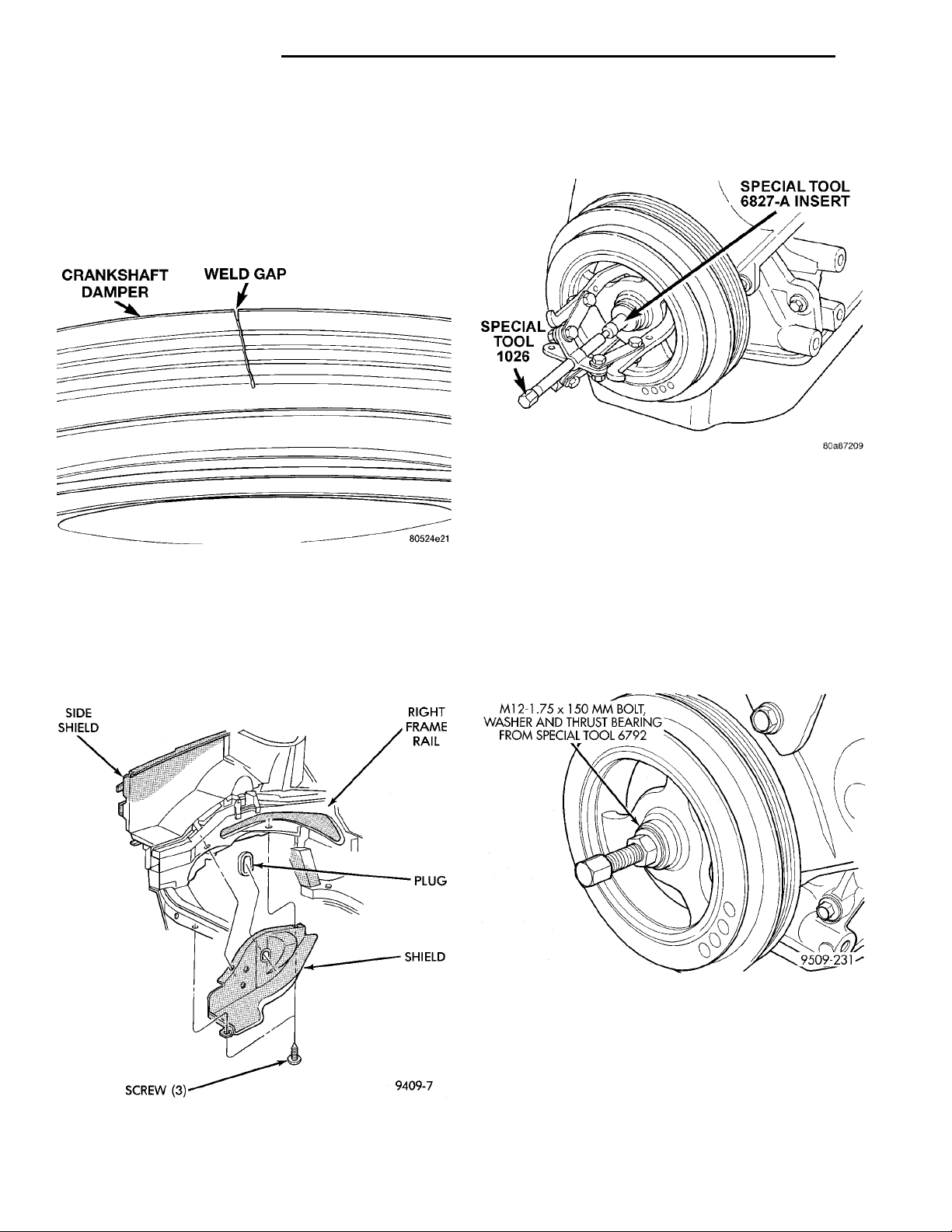
CRANKSHAFTDAMPER WELD GAP
SIDESHIELD RIGHT FRAMERAILPLUGSHIELDSCREW(3)
SPECIAL TOOL 6827–AINSERTSPECIAL TOOL 1026
M12 — 1.75 3 150 MM BOLT,WASHER AND THRUSTBEARING FROM SPECIALTOOL 6792
9 - 66 2.0L DOHC ENGINE PL
REMOVAL AND INSTALLATION (Continued)
(3) Reverse removal procedure, for rest of installa-
tion.
VIBRATION DAMPER
NOTE: If a gap is found in the crankshaft damper,
in the area where the Poly-V Generator belt rides
this is normal and is acceptable (Fig. 85).
Fig. 34 Weld Gap
REMOVAL
(1) Remove accessory drive belts. Refer to Group 7,
Cooling System for procedure outlined in that section.
(2) Raise vehicle on a hoist and remove right inner
splash shield (Fig. 86).
(3) Remove crankshaft damper bolt. Remove
damper using the large side of Special Tool 1026 and
insert 6827–A (Fig. 87).
Fig. 36 Crankshaft Damper—Removal
INSTALLATION
(1) Install crankshaft damper using M12-1.75 x
150 mm bolt, washer, thrust bearing and nut from
Special Tool 6792. Install crankshaft damper bolt and
tighten to 142 N·m (105 ft. lbs.) (Fig. 88).
(2) Install accessory drive belts. Refer to Group 7,
Cooling System Accessory Drive section for procedure.
(3) Raise vehicle on hoist and install right inner
splash shield.
Fig. 35 Right Inner Splash Shield
Fig. 37 Crankshaft Damper—Installation
Page 67
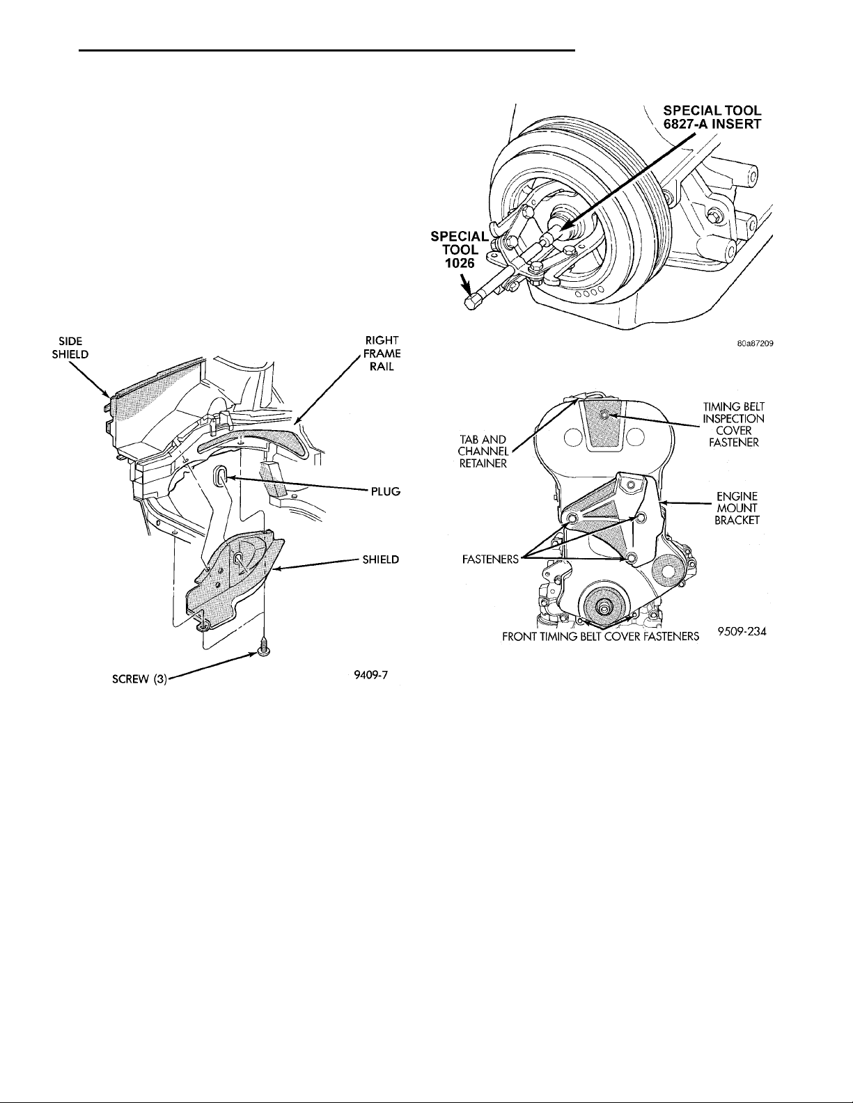
SIDESHIELD RIGHT FRAMERAILPLUGSHIELDSCREW(3)
SPECIAL TOOL 6827–AINSERTSPECIAL TOOL 1026
TAB ANDCHANNELRETAINER TIMING BELTINSPECTIONCOVER FAS-TENERENGINEMOUNTBRACKETFRONT TIMING BELT COVER FASTEN-ERSFASTENERS
PL 2.0L DOHC ENGINE 9 - 67
REMOVAL AND INSTALLATION (Continued)
TIMING BELT COVER
REMOVAL
CAUTION: Camshaft or crankshaft should not be
rotated after timing belt is removed. Damage to
valve components may occur. Always align timing
marks before removing timing belt.
(1) Remove accessory drive belts. Refer to Group 7,
Cooling System for procedure outlined in that section.
(2) Raise vehicle on a hoist and remove right inner
splash shield (Fig. 38).
Fig. 39 Crankshaft Damper—Removal
Fig. 38 Right Inner Splash Shield
(3) Remove crankshaft damper bolt. Remove
damper using Special Tool 1026 and Insert 6827–A or
equivalent (Fig. 39).
(4) Lower vehicle and place a jack under engine
(5) Remove right engine mount. Refer to procedure
outlined in this section
(6) Remove right engine mount bracket (Fig. 40)
(7) Remove timing belt cover fasteners, remove
cover (Fig. 40).
Fig. 40 Front Timing Belt Cover
INSTALLATION
(1) Install front timing cover.
(2) Install engine mount bracket.
(3) Install Right engine mount. Refer to procedure
outlined in this section for installation.
(4) Remove jack from under engine.
(5) Install crankshaft vibration damper Refer to
procedure outlined in this section for installation.
(6) Install accessory drive belts. Refer to Group 7,
Cooling System, Accessory Drive section for procedure.
(7) Raise vehicle on hoist and install right inner
splash shield.
Page 68
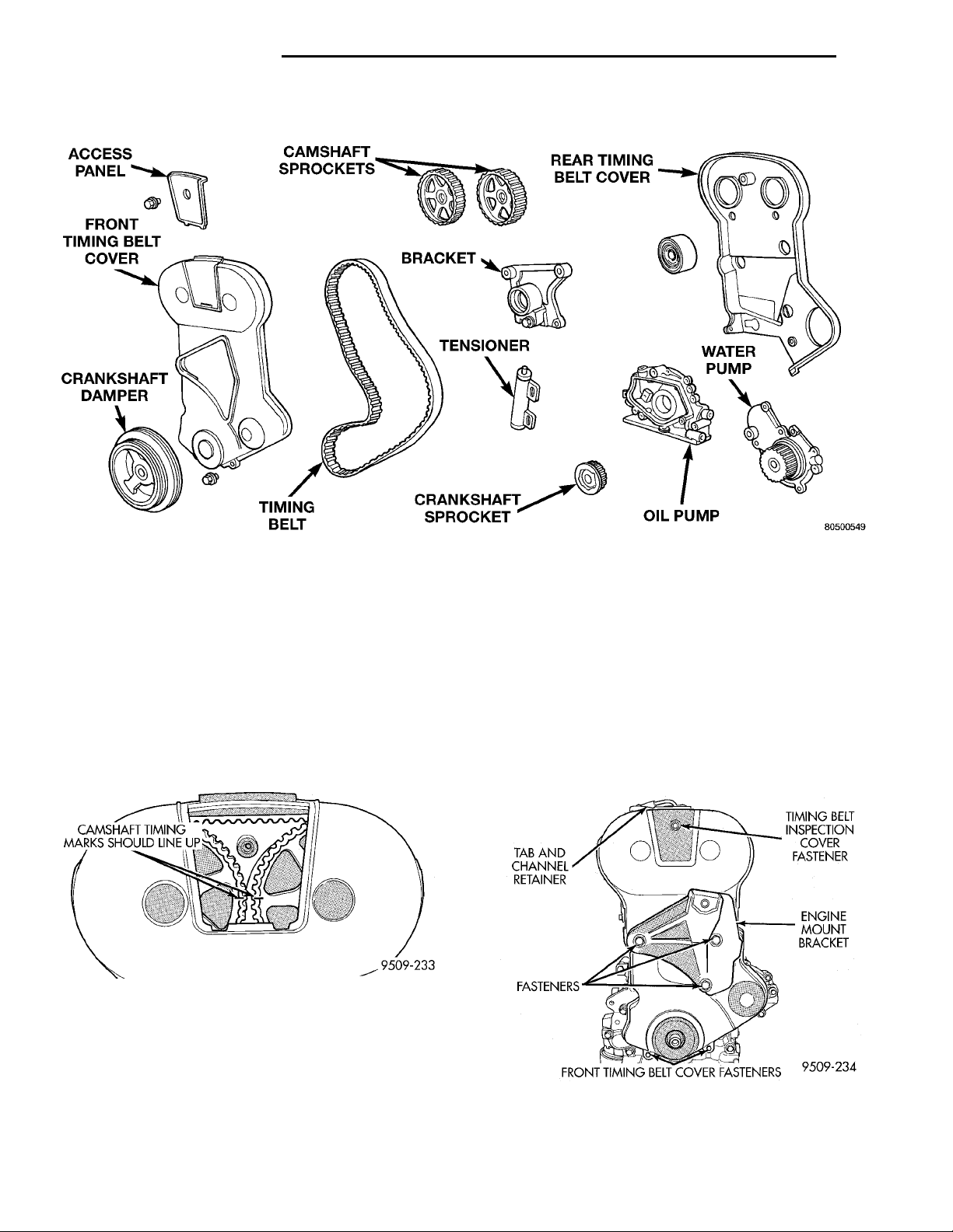
ACCESSPANEL CAMSHAFT SPROCK-ETS REAR TIMING BELT COVER WATER PUMPOIL PUMPCRANKSHAFT SPROCKETTIMING BELTCRANKSHAFTDAMPERFRONT TIMING BELTCOVER BRACKETTENSIONER
CAMSHAFT TIMING MARKS
SHOULD LINE UP
9 - 68 2.0L DOHC ENGINE PL
REMOVAL AND INSTALLATION (Continued)
TIMING BELT
TAB ANDCHANNELRETAINER TIMING BELTINSPECTIONCOVER FAS-TENERENGINEMOUNTBRACKETFRONT TIMING BELT COVER FASTEN-ERSFASTENERS
Fig. 41 Typical Timing Belt System—DOHC
CHECKING BELT TIMING —COVER
INSTALLED
(1) Remove number one spark plug.
(2) Using a dial indicator, set number one cylinder
to TDC on the compression stroke.
(3) Remove the timing belt access cover from the
engine (Fig. 41).
(4) Check the timing marks on the camshaft
sprockets, they should align with each other (Fig.
42).
Fig. 42 Camshaft Timing Check
REMOVAL
CAUTION: Camshaft or crankshaft should not be
rotate after timing belt is removed. Damage to valve
components may occur. Always align timing marks
before removing timing belt.
(1) Remove crankshaft damper bolt. Remove
damper procedure outlined in this section.
(2) Remove engine mount bracket and timing belt
cover fasteners, remove cover.
Fig. 43 Front Timing Belt Cover
Page 69
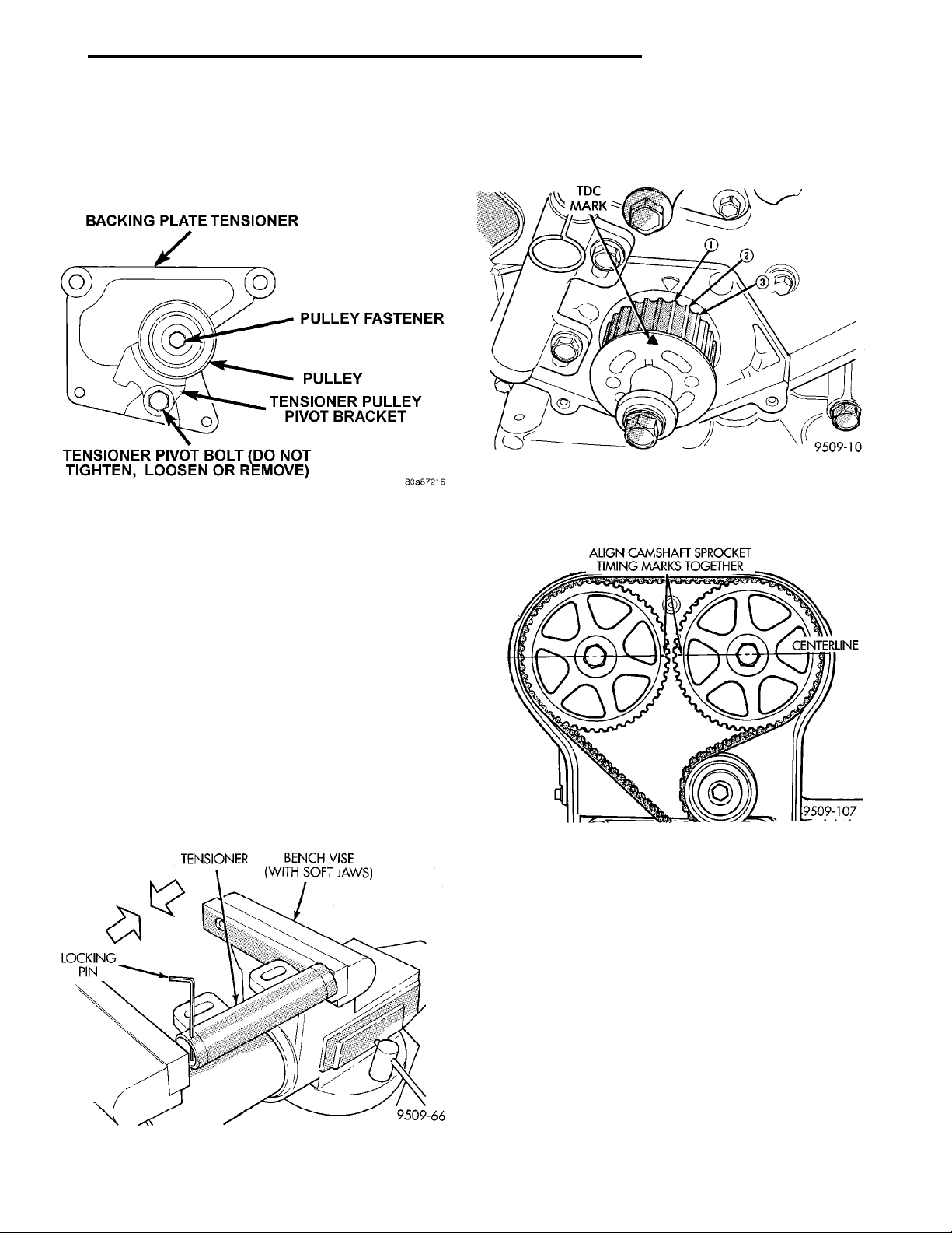
BACKING PLATE TEN-SIONERPULLEY FASTENERPULLEYTENSIONER PULLEY PIVOTBRACKETTENSIONER PIVOT BOLT(DO NOT TIGHTEN, LOOSENOR REMOVE)
TENSIONER BENCH VISE (WITH SOFTJAWS)LOCKING PIN
TDCMARK
ALIGN CAMSHAFT SPROCKET TIMINGMARKS TOGETHER CENTERLINE
PL 2.0L DOHC ENGINE 9 - 69
REMOVAL AND INSTALLATION (Continued)
(3) Align camshaft timing marks. Loosen timing
belt tensioner fasteners and remove timing belt.
CAUTION: Do not loosen, tighten, or remove the
tensioner pivot bolt (Fig. 44).
Fig. 44 Tensioner Pulley Assembly
CAMSHAFT AND CRANKSHAFT TIMING PROCEDURE AND BELT INSTALLATION —DOHC ENGINE
(1) When tensioner is removed from the engine it
is necessary to compress the plunger into the tensioner body.
(2) Place the tensioner into a vise and slowly compress the plunger (Fig. 45).
(4) Set crankshaft sprocket to TDC by aligning the
sprocket with the arrow on the oil pump housing,
then back off to 3 notches before TDC (Fig. 46).
Fig. 46 Crankshaft Sprocket Timing
(5) Set camshafts timing marks together by aligning notches on sprockets (Fig. 47).
CAUTION: Index the tensioner in the vise the same
way it is installed on the engine. This is to ensure
proper pin orientation when tensioner is installed
on the engine.
(3) When plunger is compressed into the tensioner
body install a pin through the body and plunger to
retain plunger in place until tensioner is installed.
Fig. 45 Compressing Timing Belt Tensioner
Fig. 47 Camshaft Timing Marks
(6) Rotate crankshaft 1/2 tooth counterclockwise
from TDC (Fig. 48).
(7) Install timing belt in this direction. Starting at
the crankshaft, go around the water pump sprocket,
idler pulley, camshaft sprockets and then around the
tensioner pulley (Fig. 49).
(8) Move crankshaft sprocket to TDC to take up
belt slack. Install tensioner to block but do not
tighten fasteners.
(9) Using a torque wrench on the tensioner pulley
apply 28 N·m (250 in. lbs.) of torque to tensioner
(Fig. 49).
(10) With torque being applied to the tensioner
pulley move the tensioner up against the tensioner
pulley bracket and tighten fasteners to 31 N·m (275
in. lbs.).
Page 70
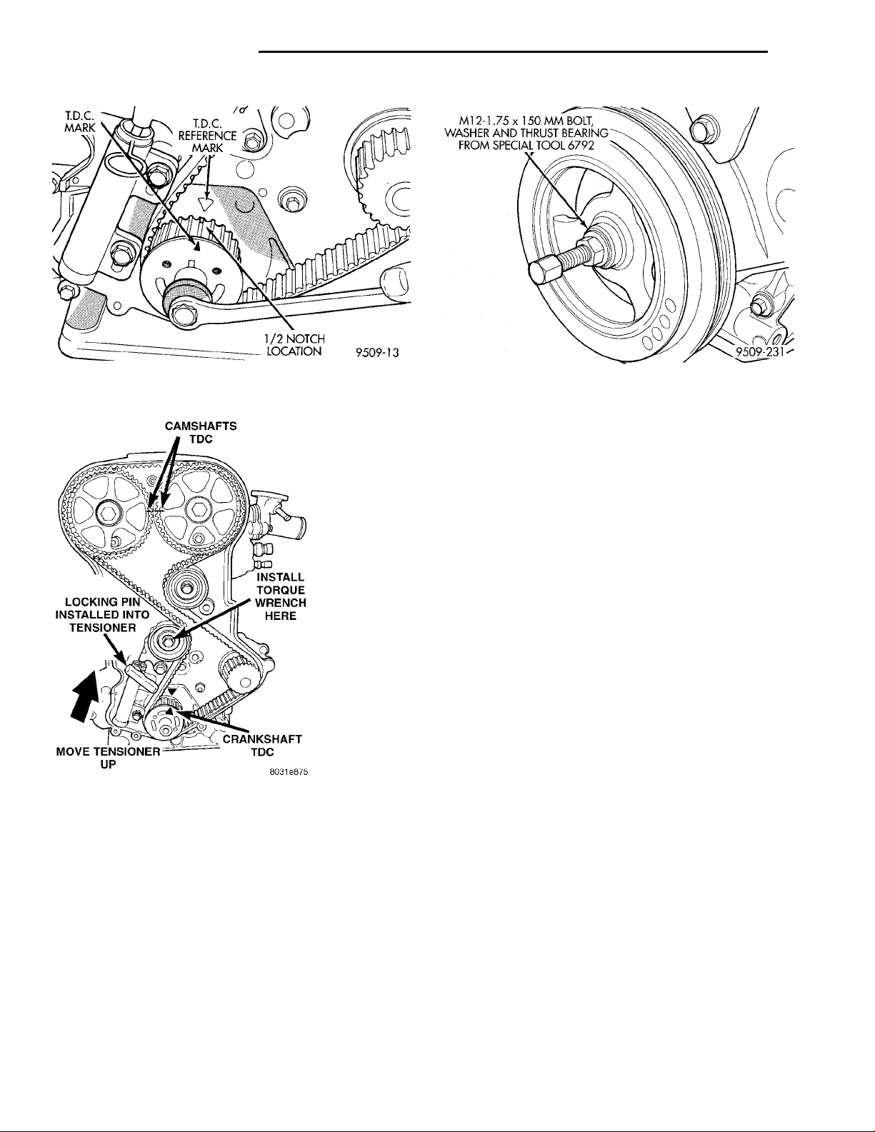
T.D.C.MARK T.D.C. REFER-ENCE MARK 1/2 NOTCH LOCATION
9 - 70 2.0L DOHC ENGINE PL
REMOVAL AND INSTALLATION (Continued)
CAMSHAFTS TDC INSTALL TORQUE WRENCHHERECRANKSHAFT TDCMOVE TENSIONER UPLOCKING PININSTALLED INTO TEN-SIONER
Fig. 48 Adjusting Crankshaft Sprocket for Timing
Belt Installation
Fig. 49 Adjusting Timing Belt Tension
(11) Pull tensioner plunger pin. Pretension is cor-
rect when pin can be removed and installed freely.
(12) Rotate crankshaft 2 revolutions and check the
alignment of the timing marks (Fig. 49).
(13) Install front half of timing cover.
(14) Install engine mount bracket.
(15) Install right engine mount. Refer to procedure
outlined in this section.
(16) Remove jack from under engine.
(17) Install crankshaft damper using M12 1.75 x
150 mm bolt, washer, thrust bearing and nut from
Special Tool 6792. Install crankshaft damper bolt and
tighten to 142 N·m (105 ft. lbs.) (Fig. 50).
Fig. 50 Crankshaft Damper—Installation
(18) Install accessory drive belts. Refer to Group 7,
Cooling System Accessory Drive section for procedure.
(19) Raise vehicle on hoist and install right inner
splash shield.
(20) Perform camshaft and crankshaft timing
relearn. Refer to Group 25, Emission Control Systems for procedure.
OIL PAN
REMOVAL
(1) Drain engine oil.
(2) Remove transmission bending bracket. Refer to
Engine Support Module Removal and Installation in
this section.
(3) Remove front engine mount and bracket. Refer
to Engine Support Module Removal and Installation
in this section.
(4) Remove transmission inspection cover.
(5) If equipped with air conditioning remove oil filter and adaptor. Refer to Oil Filter Adapter Removal
and Installation in this section.
(6) Remove oil pan.
(7) Clean oil pan and all gasket surfaces.
INSTALLATION
(1) Apply Mopar Silicone Rubber Adhesive Sealant
or equivalent at the oil pump to engine block parting
line (Fig. 55).
(2) Install a new oil pan gasket to pan.
(3) Install pan and tighten screws to 12 N·m (105
in. lbs.).
(4) Install oil filter and adaptor.
(5) Install transmission inspection cover.
(6) install front engine mount and bracket.
(7) Install transmission bending bracket.
Page 71
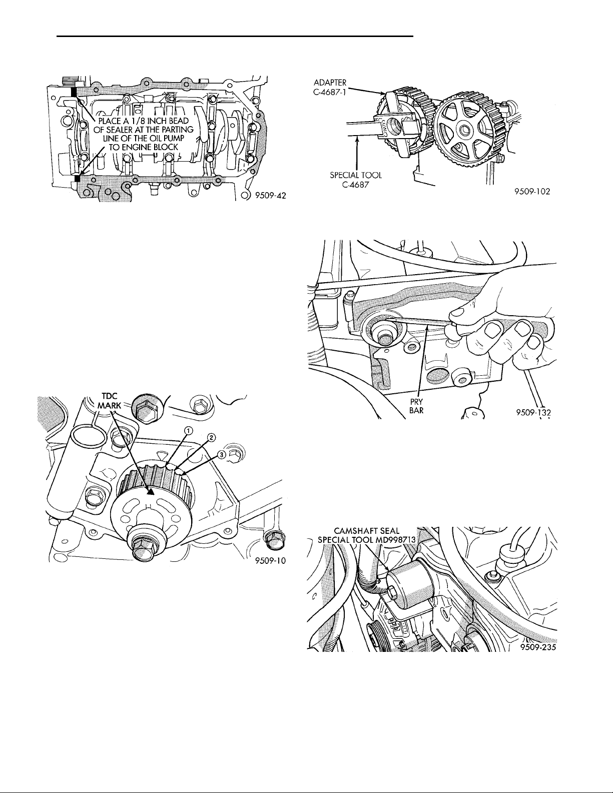
PLACE A 1/8 INCH BEAD OFSEALER AT THE PARTING LINEOF THE OIL PUMP TO ENGINEBLOCK
TDCMARK
ADAPTERC-4687–1SPECIAL TOOL C-4687
CAMSHAFT SEAL SPECIAL TOOLMD998713
PRY BAR
PL 2.0L DOHC ENGINE 9 - 71
REMOVAL AND INSTALLATION (Continued)
Fig. 51 Oil Pan Sealing
(8) Install proper amount of oil. With oil filter 4.25
Liters (4.5 Qts.). Without oil filter 3.8 Liters (4.0
Qts.)
CAMSHAFT OIL SEALS
REMOVAL
(1) Remove front timing belt cover and timing belt.
Refer to procedure outlined in this section.
CAUTION: Before removing timing belt set crankshaft sprocket 3 notches before TDC, this will prevent possible engine damage (Fig. 52).
Fig. 53 Removing / Installing Camshaft Sprocket
Bolt
Fig. 54 Removing Camshaft Oil Seals
INSTALLATION
(1) Install camshaft seal into cylinder head using
Special Tool MD 998713 until flush with the head
(Fig. 55).
(2) Install camshaft sprockets and tighten attaching bolts to 101 N·m (75 ft. lbs.).
Fig. 52 Crankshaft Sprocket 3 Notches Before TDC
(2) Hold camshaft sprocket with Special Tool
C-4687 with adaptor C4687–1 while removing /
installing bolts (Fig. 53).
(3) Remove camshaft seal using a pry bar. Be careful not to nick or damage the camshaft seal surface
or cylinder head seal retaining bore (Fig. 54).
CAUTION: Do not nick shaft seal surface or seal
bore.
(4) Shaft seal lip surface must be free of varnish,
dirt or nicks. Polish with 400 grit paper if necessary.
Fig. 55 Installing Camshaft Seals
Page 72
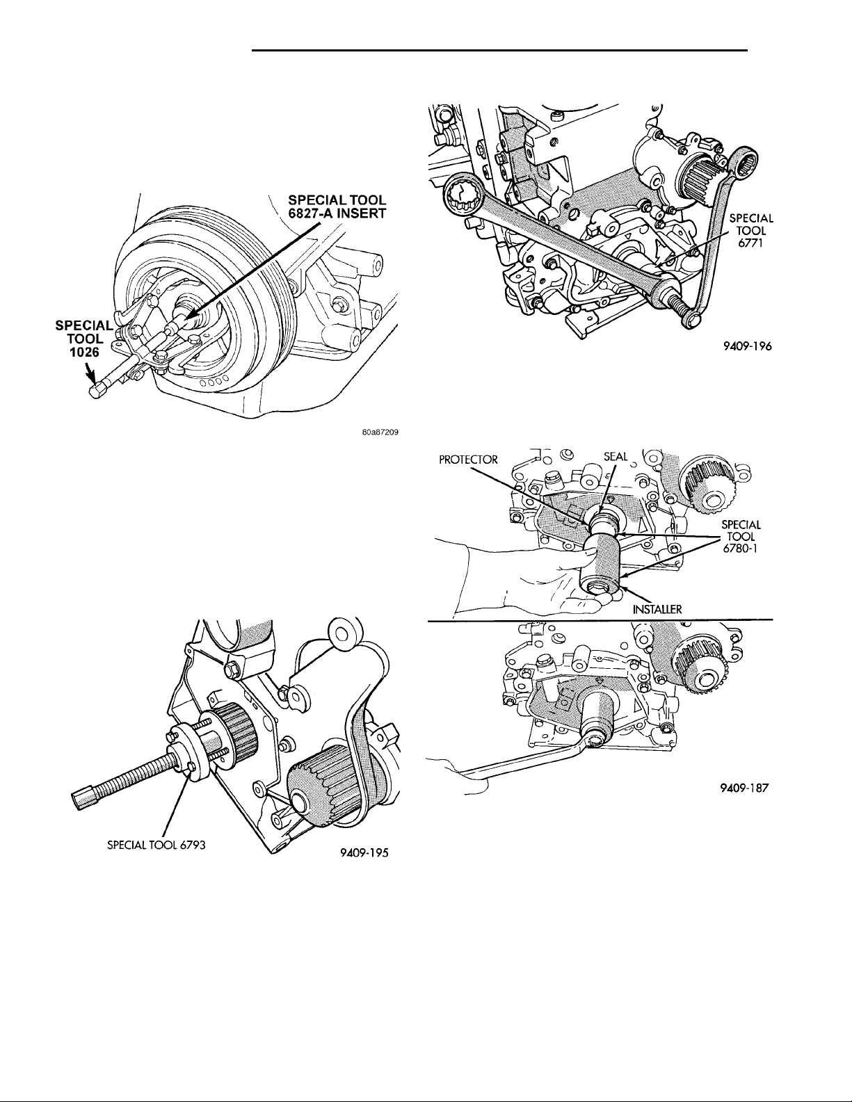
SPECIALTOOL6771
9 - 72 2.0L DOHC ENGINE PL
REMOVAL AND INSTALLATION (Continued)
PROTECTOR
SEAL
SPECIALTOOL6780–1INSTALLER
SPECIAL TOOL 6827–AINSERTSPECIAL TOOL 1026
FRONT CRANKSHAFT OIL SEAL
SPECIAL TOOL 6793
REMOVAL
(1) Using Special Tool 1026 and Insert 6827–A,
remove crankshaft damper (Fig. 56).
Fig. 56 Crankshaft Damper—Removal
(2) Remove outer timing belt cover and timing
belt. Refer to Timing Belt System outlined in this
section.
(3) Remove crankshaft sprocket using Special Tool
6793 and insert C- 4685-C2 (Fig. 57).
Fig. 58 Front Crankshaft Oil Seal—Removal
(2) Place seal into opening with seal spring
towards the inside of engine. Install seal until flush
with cover.
CAUTION: Do not nick shaft seal surface or seal
bore.
Fig. 57 Crankshaft Sprocket—Removal
(4) Using Tool 6771 to remove front crankshaft oil
seal (Fig. 58). Do not damage the seal contact area
on the crankshaft.
INSTALLATION
(1) Install new seal by using Tool 6780–1 (Fig. 59).
Fig. 59 Front Crankshaft Oil Seal—Installation
(3) Install crankshaft sprocket (Fig. 60). Using
Special Tool 6792.
NOTE: Make sure the word “front” on the sprocket
is facing you.
(4) Install timing belt and covers. Refer to Timing
Belt System in this section for installation.
(5) Install crankshaft damper (Fig. 61). Use thrust
bearing/washer and 12M-1.75 x 150 mm bolt from
Special Tool 6792. Install crankshaft damper bolt and
tighten to 142 N·m (105 ft. lbs.)
Page 73
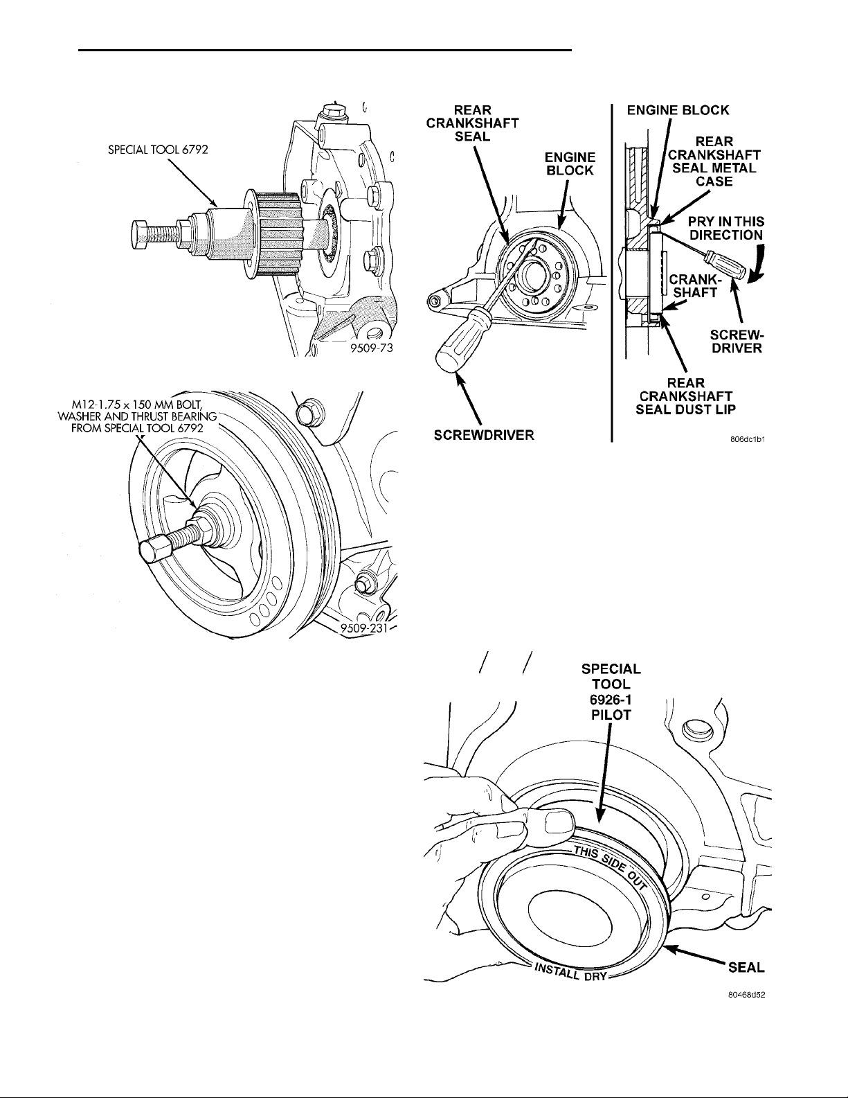
M12 — 1.75 3 150 MM BOLT,WASHER AND THRUSTBEARING FROM SPECIALTOOL 6792
SPECIAL TOOL 6792
REAR CRANKSHAFTSEAL ENGINEBLOCK ENGINE BLOCKREAR CRANK-SHAFT SEALMETAL CASEPRY IN THISDIRECTIONCRANK-SHAFTSCREW-DRIVERREAR CRANKSHAFT SEALDUST LIPSCREW-DRIVER
SPECIAL TOOL 6926–1PILOT SEAL
PL 2.0L DOHC ENGINE 9 - 73
REMOVAL AND INSTALLATION (Continued)
Fig. 60 Crankshaft Sprocket—Installation
Fig. 61 Crankshaft Damper—Installation
REAR CRANKSHAFT SEAL
REMOVAL
(1) Insert a 3/16 flat bladed screwdriver between
the dust lip and the metal case of the crankshaft
seal. Angle the screwdriver (Fig. 62) through the dust
lip against metal case of the seal. Pry out seal.
CAUTION: Do not permit the screwdriver blade to
contact crankshaft seal surface. Contact of the
screwdriver blade against crankshaft edge (chamfer) is permitted.
Fig. 62 Rear Crankshaft Oil Seal—Removal
(2) Position seal over pilot tool. Make sure you can
read the words THIS SIDE OUT on seal (Fig. 63).
Pilot tool should remain on crankshaft during installation of seal. Ensure that the lip of the seal is facing
towards the crankcase during installation.
CAUTION: If the seal is driven into the block past
flush, this may cause an oil leak.
(3) Drive the seal into the block using Special Tool
6926-2 and handle C-4171 (Fig. 64) until the tool bottoms out against the block (Fig. 65).
INSTALLATION
CAUTION: If burr or scratch is present on the
crankshaft edge (chamfer), cleanup with 400 grit
sand paper to prevent seal damage during installation of new seal.
NOTE: When installing seal, no lube on seal is
needed.
(1) Place Special Tool 6926-1 on crankshaft. This is
a pilot tool with a magnetic base (Fig. 63).
Fig. 63 Rear Crankshaft Seal and Special Tool 6926-1
Page 74
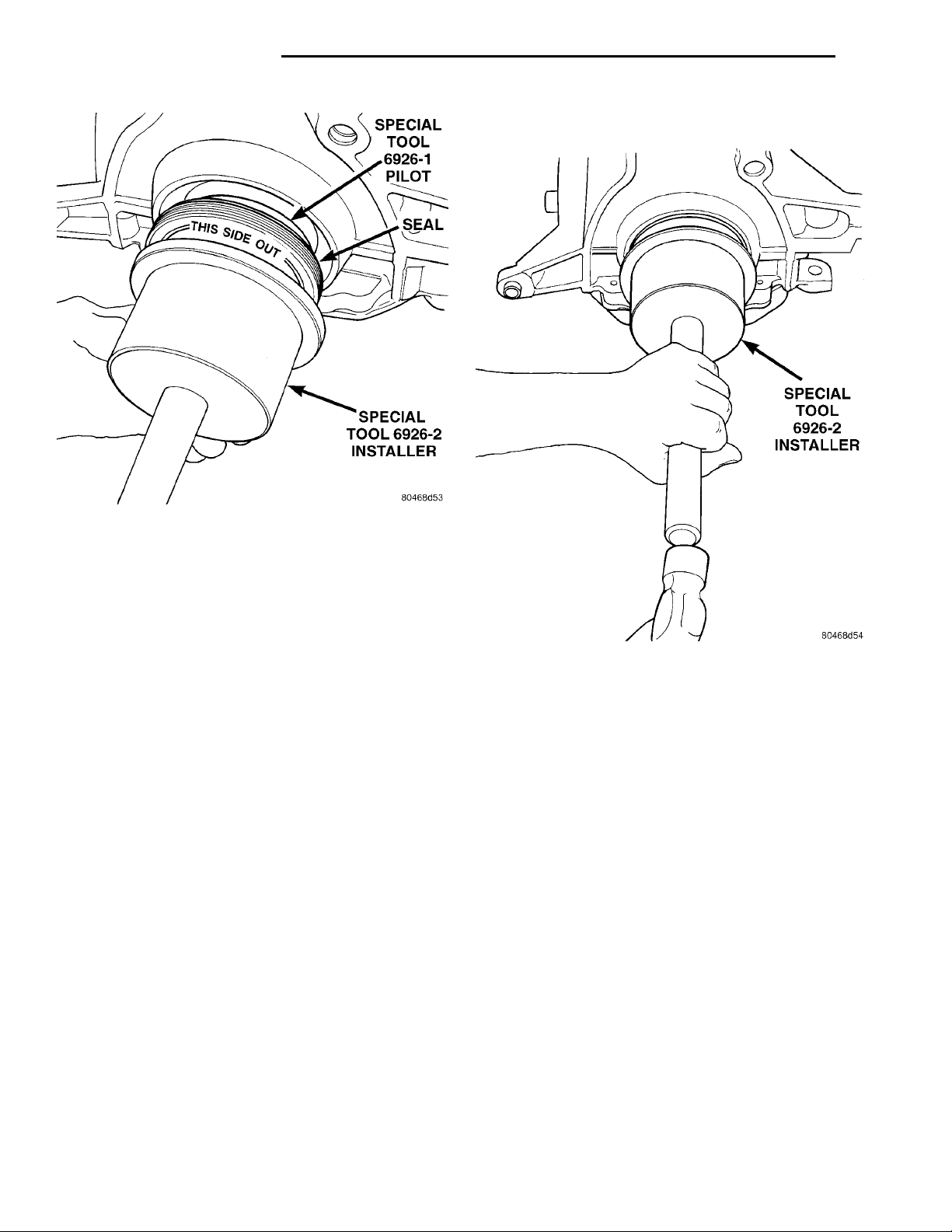
SPECIALTOOL6926–1PILOT
SPECIAL TOOL6792–2 INSTALLER
SEAL
SPECIALTOOL6926–2INSTALLER
9 - 74 2.0L DOHC ENGINE PL
REMOVAL AND INSTALLATION (Continued)
Fig. 64 Crankshaft Seal Special Tool 6926-2
Fig. 65 Rear Crankshaft Seal—Installation
Page 75
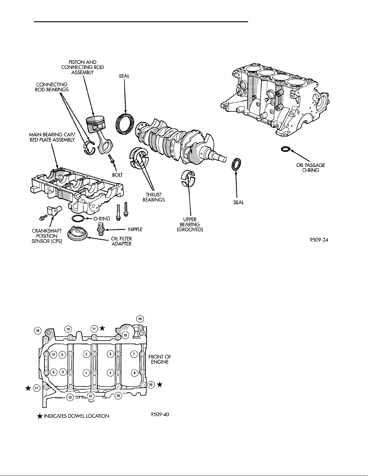
PISTON AND CONNECT-ING ROD ASSEMBLY SEAL OIL PASSAGEO-RINGSEALUPPER BEARING(GROOVED)THRUSTBEARINGSNIPPLEOIL FILTER ADAPTERO-RINGCRANKSHAFTPOSITION SEN-SOR (CPS) BOLTMAIN BEARING CAP/BED PLATE ASSEMBLYCONNECTING RODBEARINGS
FRONTOFENGINEINDICATES DOWEL LOCA-TION
PL 2.0L DOHC ENGINE 9 - 75
REMOVAL AND INSTALLATION (Continued)
CRANKSHAFT
REMOVAL
(1) Remove oil filter and adapter from bedplate.
(2) Remove oil pan.
(3) Remove crankshaft sprocket and oil pump both
procedures outlined in this section.
(4) Remove all main bearing cap and bedplate
bolts from the engine block (Fig. 66).
Fig. 66 Bedplate Bolts
(5) Using a mallet tap the bedplate loose from the
engine block dowel pins.
CAUTION: Do not pry up on one side of the bedplate. Damage may occur to cylinder block and bedplate alignment.
(6) Bedplate should be removed evenly from the
cylinder block dowel pins.
(7) Lift out crankshaft from cylinder block. Be sure
not to damage the main bearings or journals when
removing the crankshaft.
CRANKSHAFT MAIN BEARINGS LOCATION
The crankshaft is supported in five main bearings.
All upper bearing shells in the crankcase have oil
grooves. All lower bearing shells installed in the (bedplate) main bearing cap are plain. Crankshaft end
play is controlled by a flanged bearing on the number
three main bearing journal (Fig. 67).
NOTE: The upper and lower main Bearing shells
are Not interchangeable. The lower shells have a
revised tab to prevent improper installation.
CRANKSHAFT MAIN JOURNALS INSPECTION
The crankshaft journals should be checked for
excessive wear, taper and scoring. Limits of taper or
out-of-round on any crankshaft journals should be
Page 76
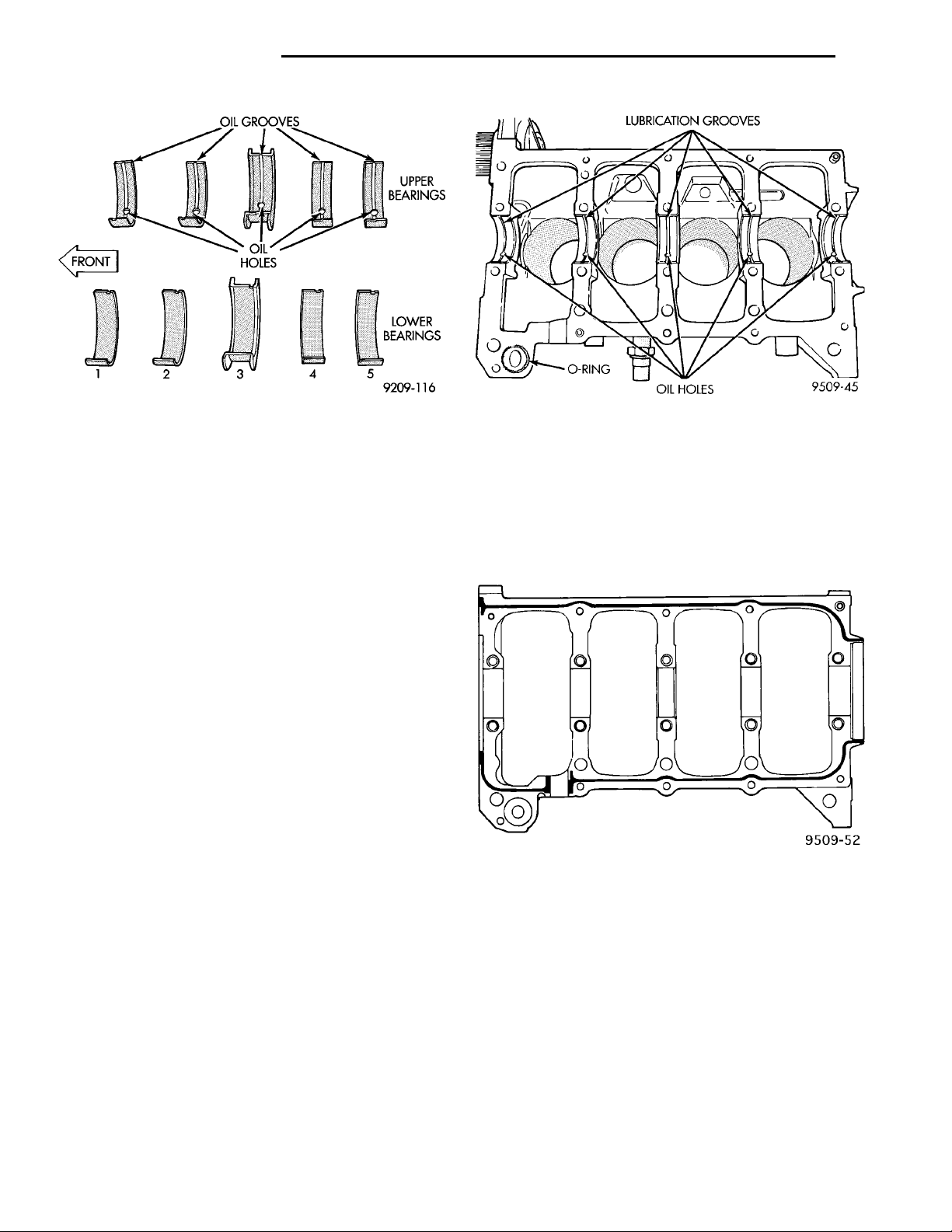
OIL GROOVES UPPERBEARINGSLOWERBEARINGSOIL HOLESFRONT
LUBRICATION GROOVESO-RING OIL HOLES
9 - 76 2.0L DOHC ENGINE PL
REMOVAL AND INSTALLATION (Continued)
Fig. 67 Main Bearing Identification
held to .025 mm (.001 inch). Journal grinding should
not exceed .305 mm (.012 inch) under the standard
journal diameter. DO NOT grind thrust faces of
Number 3 main bearing. DO NOT nick crank pin or
bearing fillets. After grinding, remove rough edges
from crankshaft oil holes and clean out all passages.
CAUTION: With the nodular cast iron crankshafts
used it is important that the final paper or cloth polish after any journal regrind be in the same direction as normal rotation in the engine.
Upper and lower Number 3 bearing halves are
flanged to carry the crankshaft thrust loads and are
NOT interchangeable with any other bearing halves
in the engine (Fig. 67). All bearing cap bolts removed
during service procedures are to be cleaned and oiled
before installation. Bearing shells are available in
standard and the following undersized: 0.016 mm
(.0006 inch), .032 mm (.0012 inch), .250 mm (.010
inch). Never install an undersize bearing that will
reduce clearance below specifications.
INSTALLATION
(1) Install the main bearing shells with the lubrication groove in the cylinder block. Install O-ring
into recess in the block (Fig. 68).
(2) Make certain oil holes in block line up with oil
hole in bearings and bearing tabs seat in the block
tab slots.
CAUTION: Do Not get oil on the bedplate mating
surface. It will affect the sealer ability to seal the
bedplate to cylinder block.
(3) Oil the bearings and journals and install
crankshaft and O-ring in cylinder block.
Fig. 68 Installing Main Bearing Upper Shell
CAUTION: Use only the specified anaerobic sealer
on the bedplate or damage may occur to the
engine.
(4) Apply 1.5 to 2.0 mm (0.059 to 0.078 in.) bead of
Mopar Torque Cure Gasket Maker to cylinder block
as shown in (Fig. 69).
Fig. 69 Main Bearing Caps/Bedplate Sealing
(5) Install lower main bearings into main bearing
cap/bedplate. Make certain the bearing tabs are
seated into the bedplate slots. Install the main bearing/bedplate into engine block.
(6) Before installing the bolts the threads should
be oiled with clean engine oil, wipe off any excess oil.
(7) Install main bearing bedplate to engine block
bolts 11, 17 and 20 finger tight. Tighten this bolts
down together until the bedplate contacts the cylinder block. Torque bolts to 30 N·m (22 ft. lbs.) (Fig.
70).
(8) Install main bearing bedplate to engine block
bolts (1 thru 10) and torque each bolt to 81 N·m (60
ft. lbs.) in sequence shown in (Fig. 70).
Page 77
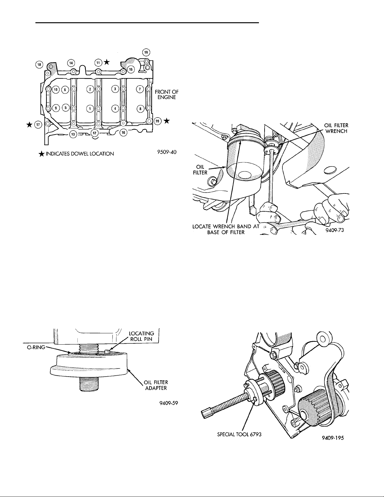
O-RING
OIL FILTERADAPTER
LOCATING ROLL
FRONTOFENGINEINDICATES DOWEL LOCA-TION
PIN
PL 2.0L DOHC ENGINE 9 - 77
REMOVAL AND INSTALLATION (Continued)
against the seam at the base of the filter. The seam,
joining the can to the base is reinforced by the
base plate.
(1) Turn counterclockwise to remove.
OIL FILTER OIL FILTERWRENCHLOCATE WRENCH BAND ATBASE OF FILTER
(2) To install, lubricate new filter gasket. Check
filter mounting surface. The surface must be smooth,
flat and free of debris or old pieces of rubber. Screw
filter on until gasket contacts base. Tighten to 21
N·m (15 ft. lbs.).
SPECIAL TOOL 6793
Fig. 70 Main Bearing Caps/Bedplate Torque
Sequence
(9) Install main bearing bedplate to engine block
bolts (11 thru 20), with baffle studs in positions 12,
13 and 16 and torque each bolt to 30 N·m (22 ft. lbs.)
in sequence shown in (Fig. 70).
(10) After the main bearing bedplate is installed,
check the crankshaft turning torque. The turning
torque should not exceed 5.6 N·m (50 in. lbs.).
(11) Install oil pump. If crankshaft end play is to
be checked refer to service procedures in this section.
(12) Install crankshaft sprocket.
(13) Install oil filter adapter and filter. Refer to
procedure outlined in this section.
OIL FILTER ADAPTER
REMOVE AND INSTALL
Ensure O-ring is in the groove on adapter. Align
roll pin into engine block and tighten assembly to 80
N·m (60 ft. lbs.) (Fig. 71).
OIL PUMP
REMOVAL
(1) Disconnect negative battery cable.
(2) Remove Timing Belt. Refer to Timing Belt Sys-
tem, in this section.
(3) Remove Oil Pan. Refer to Oil Pan Removal in
this section.
(4) Remove Crankshaft Sprocket using Special Tool
6793 and insert C4685–C2 (Fig. 73).
Fig. 72 Engine Oil Filter
Fig. 71 Engine Oil Filter Adapter to Engine Block
OIL FILTER
REMOVE AND INSTALL
CAUTION: When servicing the oil filter (Fig. 72)
avoid deforming the filter, install tool band strap
Fig. 73 Crankshaft Sprocket—Removal
(5) Remove oil pick-up tube.
Page 78
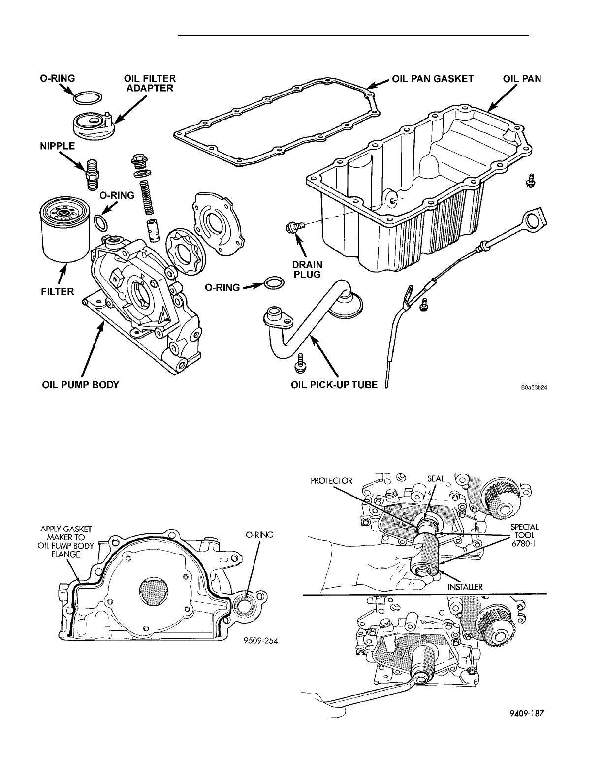
APPLY GASKETMAKER TO OILPUMP BODYFLANGE O-RING
O-RINGOIL FILTER ADAPTEROIL PAN GASKETOIL PANOIL PICK-UP TUBEDRAIN PLUGO-RINGOIL PUMP BODYFILTERO-RINGNIPPLE
9 - 78 2.0L DOHC ENGINE PL
REMOVAL AND INSTALLATION (Continued)
Fig. 74 Oil Pump and Tube
(6) Remove oil pump, (Fig. 74) and front crankshaft seal.
INSTALLATION
(1) Make sure all surfaces are clean and free of oil
and dirt.
(2) Apply Mopar Gasket Maker to oil pump as
shown in (Fig. 75). Install oil ring into oil pump body
discharge passage.
Fig. 75 Oil Pump Sealing
(3) Prime oil pump before installation.
(4) Align oil pump rotor flats with flats on crankshaft as you install the oil pump to the block.
PROTECTOR
SEAL
SPECIALTOOL6780–1INSTALLER
(5) Torque all oil pump attaching bolts to 28 N·m
(250 in. lbs.)
(6) Install new front crankshaft seal using Special
Tool 6780 (Fig. 76).
NOTE: Front crankshaft seal MUST be out of pump
to align, or damage may result.
Fig. 76 Front Crankshaft Seal—Installation
Page 79
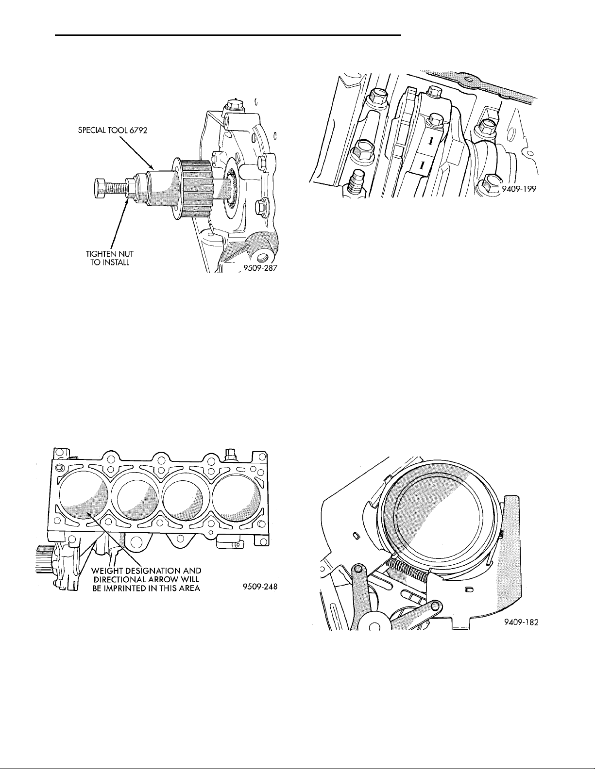
PL 2.0L DOHC ENGINE 9 - 79
REMOVAL AND INSTALLATION (Continued)
(7) Install crankshaft sprocket, using Special Tool
6792 (Fig. 77).
Fig. 79 Identify Connecting Rod to Cylinder
tion assemblies. The weight designation stamps
should face toward the timing belt side of the engine.
(4) Pistons and connecting rods must be removed
from top of cylinder block. Rotate crankshaft so that
each connecting rod is centered in cylinder bore.
Fig. 77 Crankshaft Sprocket—Installation
(8) Install oil pump pick-up tube and oil pan.
(9) Install Timing Belt. Refer to Timing Belt
Installation in this section.
(5) Remove connecting rod cap bolts Do not use
old bolts if reinstalling connecting rod. Push
each piston and rod assembly out of cylinder bore.
NOTE: Be careful not to nick crankshaft journals.
PISTON AND CONNECTING ROD
REMOVAL
(1) Remove top ridge of cylinder bores with a reliable ridge reamer before removing pistons from cylinder block. Be sure to keep tops of pistons
covered during this operation . Mark piston with
matching cylinder number (Fig. 78).
Fig. 78 Piston Markings
(2) Remove oil pan. Scribe the cylinder number on
the side of the rod and cap (Fig. 79) for identification.
(3) Pistons will have a stamping in the approximate location shown in (Fig. 78). These stamps will
be either a directional arrow or a weight identification for the assembly. L is for light and H is for
heavy. These assemblies should all be the same
weight class. Service piston assemblies are marked
with a S and can be used with either L or H produc-
(6) After removal, install bearing cap on the mat-
ing rod.
(7) Piston and Rods are serviced as an assembly.
PISTON RING—REMOVAL
(1) ID mark on face of upper and intermediate pis-
ton rings must point toward piston crown.
(2) Using a suitable ring expander, remove upper
and intermediate piston rings (Fig. 80).
Fig. 80 Piston Rings—Removing and Installing
(3) Remove the upper oil ring side rail, lower oil
ring side rail and then oil ring expander from piston.
(4) Clean ring grooves of any carbon deposits.
Page 80
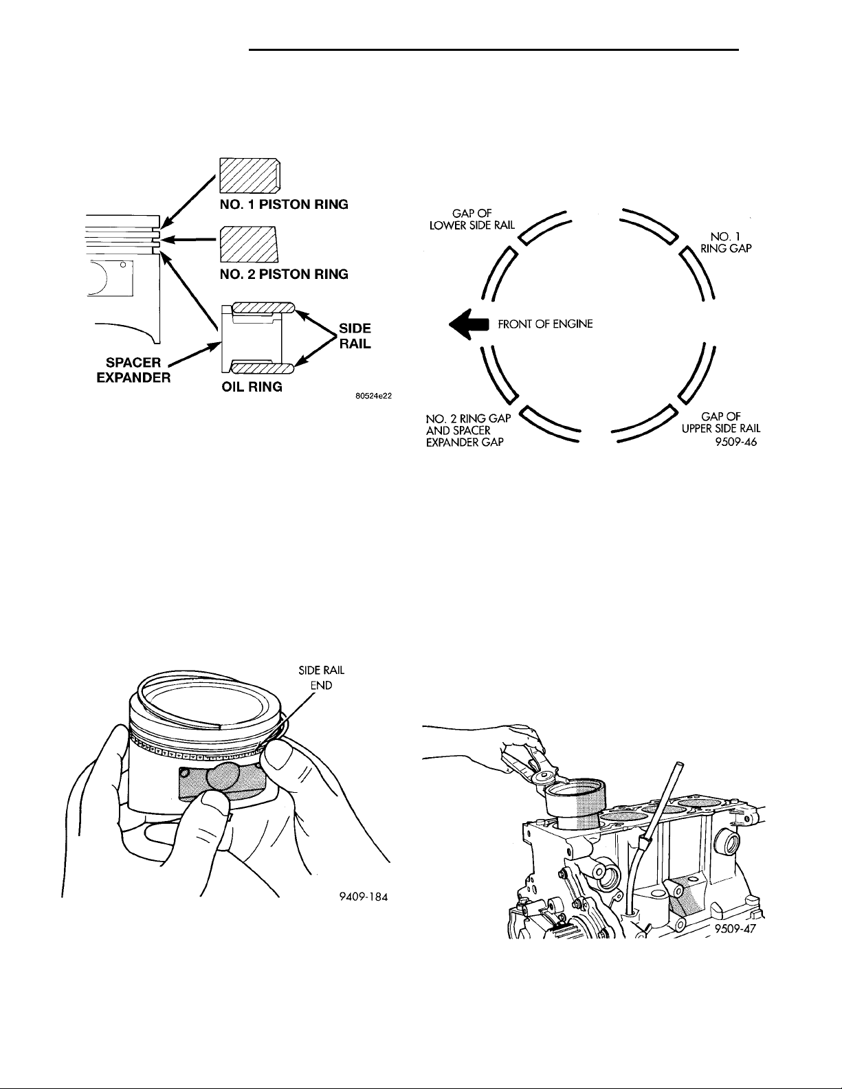
NO. 1 PISTON RINGNO. 2 PISTON RING SIDE RAILOIL RINGSPACEREXPANDER
SIDE RAIL END
GAP OF LOWERSIDE RAIL NO. 1 RING GAPGAP OF UPPERSIDE RAILNO. 2 RING GAP ANDSPACER EXPANDERGAP FRONT OF ENGINE
9 - 80 2.0L DOHC ENGINE PL
REMOVAL AND INSTALLATION (Continued)
PISTON RINGS—INSTALLATION
(1) Install rings with manufacturers I.D. mark facing up, to the top of the piston (Fig. 81).
Fig. 81 Piston Ring Installation
CAUTION: Install piston rings in the following
order:
a. Oil ring expander.
b. Upper oil ring side rail.
c. Lower oil ring side rail.
d. No. 2 Intermediate piston ring.
e. No. 1 Upper piston ring.
f. Install the side rail by placing one end between
the piston ring groove and the expander. Hold end
firmly and press down the portion to be installed
until side rail is in position. Do not use a piston
ring expander (Fig. 82).
(4) Position piston ring end gaps as shown in (Fig.
83).
(5) Position oil ring expander gap at least 45° from
the side rail gaps but not on the piston pin center or
on the thrust direction. Staggering ring gap is important for oil control.
Fig. 83 Piston Ring End Gap Position
PISTON AND ROD —INSTALLATION
(1) Before installing pistons and connecting rod
assemblies into the bore, be sure that compression
ring gaps are staggered so that neither is in line with
oil ring rail gap.
(2) Before installing the ring compressor, make
sure the oil ring expander ends are butted and the
rail gaps located as shown in (Fig. 83).
(3) Immerse the piston head and rings in clean
engine oil, slide the ring compressor, over the piston
(Fig. 84). Be sure position of rings does not
change during this operation .
Fig. 82 Installing Side Rail
(2) Install upper side rail first and then the lower
side rail.
(3) Install No. 2 piston ring and then No. 1 piston
ring (Fig. 81).
Fig. 84 Installing Piston
(4) The weight stamp designation L or H will be in
the front half of the piston should face toward the
front of the engine for SOHC engine. The arrow
Page 81
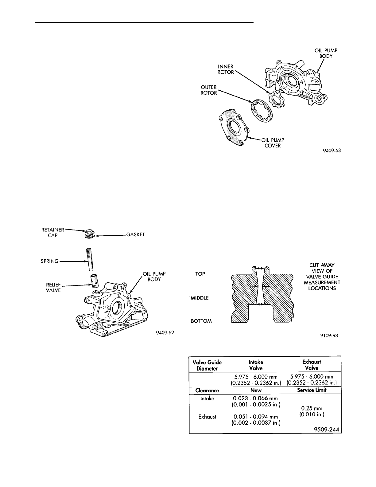
RETAINER CAP GASKETOIL PUMP BODYRELIEFVALVESPRING
TOPMIDDLEBOTTOM CUT AWAY VIEW OFVALVE GUIDE MEA-SUREMENT LOCA-TIONS
OIL PUMPBODYOIL PUMP COVEROUTERROTOR INNER ROTOR
PL 2.0L DOHC ENGINE 9 - 81
REMOVAL AND INSTALLATION (Continued)
should face toward the front of the engine for DOHC
engine (Fig. 78).
(5) Rotate crankshaft so that the connecting rod
journal is on the center of the cylinder bore. Insert
rod and piston assembly into cylinder bore and guide
rod over the crankshaft journal.
(6) Tap the piston down in cylinder bore, using a
hammer handle. At the same time, guide connecting
rod into position on connecting rod journal.
(7) Install rod caps. Install New bolts and tighten
to 27 N·m (20 ft.lb.) Plus 1/4 turn.
DISASSEMBLY AND ASSEMBLY
OIL PUMP
(1) To remove the relief valve, proceed as follows:
(2) Remove the threaded plug and gasket from the
oil pump (Fig. 89).
CAUTION: Oil pump pressure relief valve must be
installed as shown in (Fig. 89) or serious damage
may occur.
(3) Remove spring and relief valve (Fig. 89).
(3) Before removing valves, remove any burrs
from valve stem lock grooves to prevent damage to the valve guides. Identify valves to insure
installation in original location.
VALVE GUIDES
(1) Remove carbon and varnish deposits from
inside of valve guides with a reliable guide cleaner.
(2) Using a small hole gauge and a micrometer,
measure valve guides in 3 places top, middle and bottom (Fig. 87). Refer to (Fig. 88) for specifications.
Replace guides if they are not within specification.
Fig. 86 Oil Pump
Fig. 85 Oil Pressure Relief Valve
(4) Remove oil pump cover screws, and lift off
cover.
(5) Remove pump rotors.
(6) Wash all parts in a suitable solvent and inspect
carefully for damage or wear (Fig. 90).
VALVE SERVICE WITH CYLINDER HEAD REMOVED
REMOVAL
(1) With cylinder head removed, compress valve
springs using Special Tool MD 998735 or equivalent.
(2) Remove valve retaining locks, valve spring
retainers, valve stem seals and valve springs.
Fig. 87 Checking Wear on Valve Guide—Typical
Fig. 88 Valve Guide Specification
Page 82
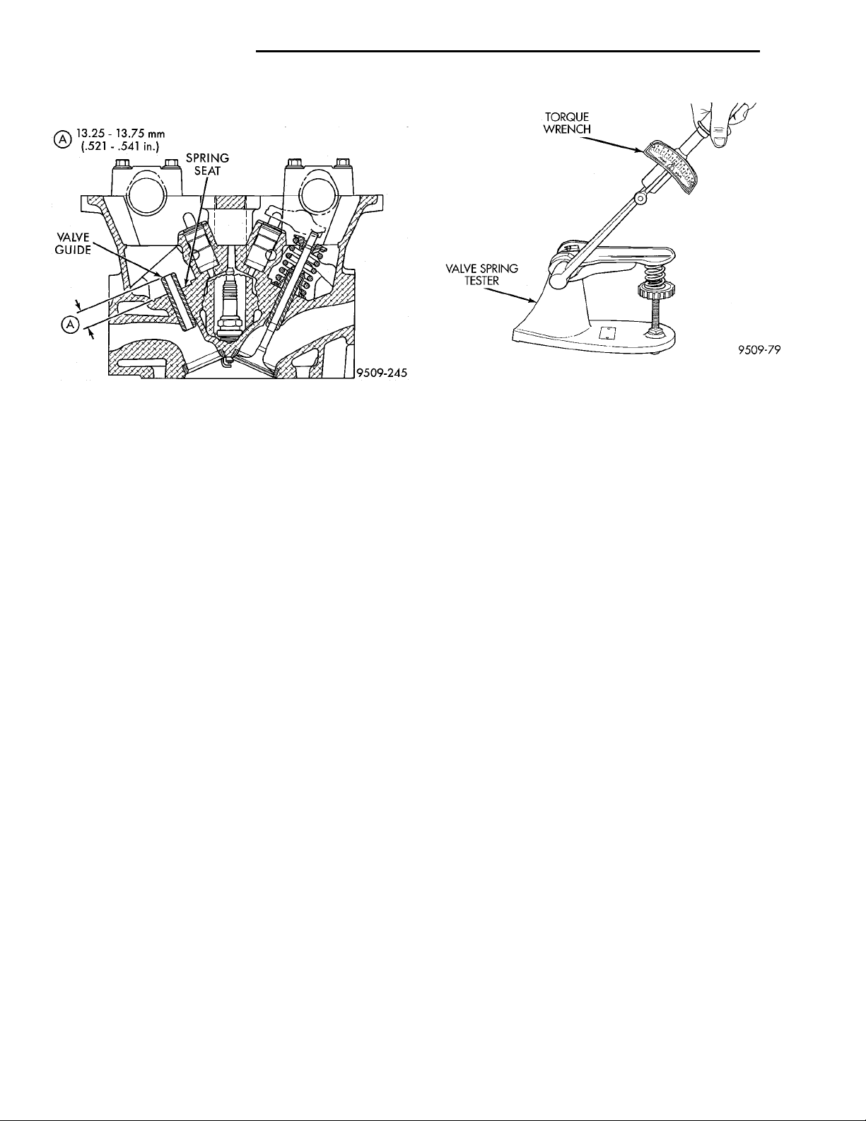
13.25 — 13.75 mm(.521 — .541 in.) SPRING SEATVALVEGUIDE
TORQUE WRENCHVALVE SPRINGTESTER
9 - 82 2.0L DOHC ENGINE PL
DISASSEMBLY AND ASSEMBLY (Continued)
CHECK VALVE GUIDE HEIGTH
Fig. 89 Testing Valve Spring
Valve Guide Heigth
TESTING VALVE SPRINGS
(1) Whenever valves have been removed for inspection, reconditioning or replacement, valve springs
should be tested Special Tool C-647. As an example,
the compression length of the spring to be tested is
33.34 mm (1-5/16 inches). Turn tool table until surface is in line with the 33.34 mm (1-5/16 inch) mark
on the threaded stud and the zero mark on the front.
Place spring over stud on the table and lift compressing lever to set tone device (Fig. 89). Pull on torque
wrench until ping is heard. Take reading on torque
wrench at this instant. Multiply this reading by two.
This will give the spring load at test length. Fractional measurements are indicated on the table for
finer adjustments. Discard the springs that do not
meet specifications. The Following specifications
apply to both intake and exhaust valve springs;
• Valve Closed Nominal Tension— 58 ft. lbs. @
38.0 mm (1.50 in.)
• Valve Open Nominal Tension— 130 ft. lbs. @
29.25 mm (1.17 in.)
(2) Verify springs are not distorted with a steel
square and surface plate, check springs from both
ends. If the spring is more than 1.5 mm (1/16 inch)
out of square, install a new spring.
REFACING VALVES AND VALVE SEATS
(1) The intake and exhaust valve seats and valve
face have a 45 and a 45 1/2 degree angles.
(2) Inspect the remaining margin after the valves
are refaced (Fig. 91). Intake valves with less than 1.2
mm (3/64 inch.) margin and Exhaust valves with less
than 0.9 mm (1/32 inch.) margin should be discarded.
(3) When refacing valve seats, it is important that
the correct size valve guide pilot be used for the
reseating stones. A true and complete surface must
be obtained.
(4) Measure the concentricity of valve seat and
valve guide using a valve seat runout dial indicator.
Total runout should not exceed. 0.051 mm (0.002
inch.) (total indicator reading).
(5) Inspect the valve seat with Prussian blue to
determine where the valve contacts the seat. To do
this, coat valve seat LIGHTLY with Prussian blue
then set valve in place. Rotate the valve with light
pressure. If the blue is transferred to the center of
valve face, contact is satisfactory. If the blue is transferred to top edge of the valve face, lower valve seat
with a 15 degrees stone. If the blue is transferred to
the bottom edge of valve face raise valve seat with a
65 degrees stone.
• Intake valve seat diameter is 34.37 - 34.63 mm
(1.353 - 1.363 inch.)
• Exhaust valve seat diameter is 29.37 29.63 mm
(1.156 1.166 inch.)
(6) Valve seats which are worn or burned can be
reworked, provided that correct angle and seat width
are maintained. The intake valve seat must be serviced when the valve seat width is 2.0 mm (0.079 in.)
or greater. The exhaust valve seat must be serviced
when the valve seat width is 2.5 mm (0.098 in.) or
greater. Otherwise the cylinder head must be
replaced. Refer to (Fig. 90) for valve specifications.
(7) When seat is properly positioned the width of
intake and exhaust seats should be 0.90 to 1.30 mm
(0.035 to 0.051 inch.) (Fig. 92).
(8) Check valve tip height dimensions A after
grinding the valve seats or faces (Fig. 93). Grind
valve tip to 47.99 mm (1.889 in.) for exhaust valve
and 48.04 mm (1.891 in.) for intake valve when
installed in the head (Fig. 93). The valve tip chamfer
may need to be reground to prevent seal damage
when the valve is installed.
Page 83
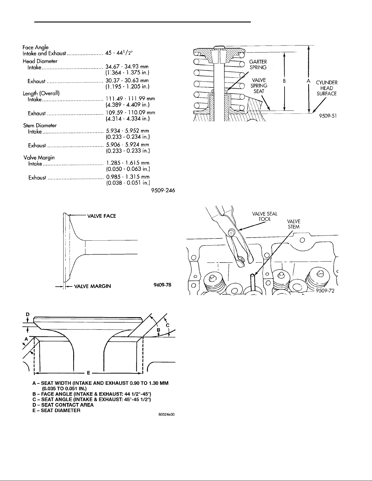
PL 2.0L DOHC ENGINE 9 - 83
DISASSEMBLY AND ASSEMBLY (Continued)
Fig. 93 Checking Spring Installed Height and Valve
Tip Height Dimensions
(2) Install new valve stem seals on all valves using
a valve stem seal tool (Fig. 94). The valve stem seals
should be pushed firmly and squarely over valve
guide.
CAUTION: If oversize valves are used, there is only
one oversize valve available. The same stem seal is
used on both the standard and oversize valve.
Fig. 90 Valve Specifications
A-SEAT WIDTH (INTAKE AND EXHAUST 0.90 TO 1.30 MM (0.035 TO 0.051 IN.)B-FACE ANGLE (INTAKE & EXHAUST: 44 1/2°–45°)C-SEAT ANGLE (INTAKE & EXHAUST: 45°–45 1/2°)D-SEAT CONTACT AREAE-SEAT DIAMETER
Fig. 91 Refacing Intake and Exhaust Valves
Fig. 92 Refacing Valve Seats
VALVE INSTALLATION
(1) Coat valve stems with clean engine oil and
insert in cylinder head.
Fig. 94 Valve Stem Oil Seal Tool
(3) Install valve springs and retainers. Compress
valve springs only enough to install locks, taking
care not to misalign the direction of compression.
Nicked valve stems may result from misalignment of
the valve spring compressor.
CAUTION: When depressing the valve spring
retainers with valve spring compressor the locks
can become dislocated. Check to make sure both
locks are in their correct location after removing
tool.
(4) Check the valve spring installed height B after
refacing the valve and seat (Fig. 93). Make sure measurements are taken from top of spring seat to the
bottom surface of spring retainer. If height is greater
than 38.75 mm (1.525 in.), install a 7.620 mm (0.030
inch.) spacer under the valve spring seat to bring
spring height back within specification.
Page 84
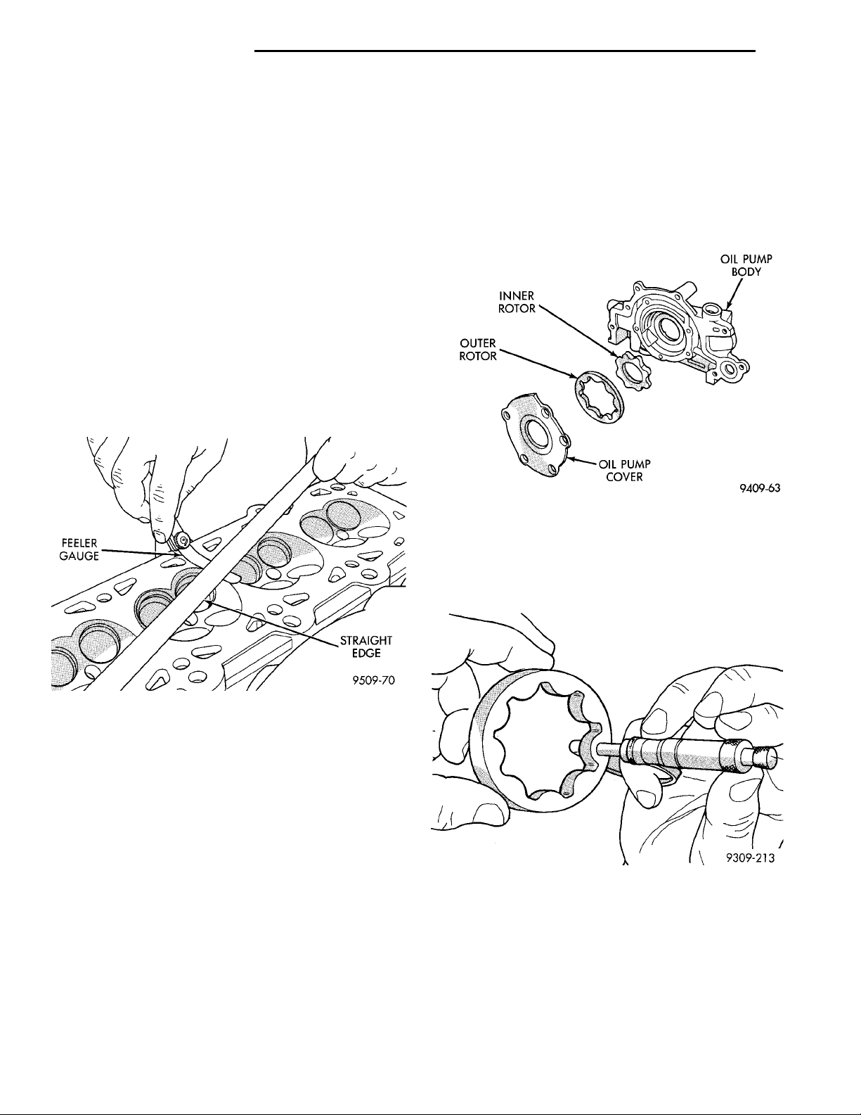
9 - 84 2.0L DOHC ENGINE PL
DISASSEMBLY AND ASSEMBLY (Continued)
(5) Install cam followers and camshaft as previ-
ously described in this section.
(6) Checking dry lash. Dry lash is the amount of
clearance that exists between the base circle of an
installed cam and the rocker arm roller when the
adjuster is drained of oil and completely collapsed.
Specified dry lash is 1.17 mm (0.046 in.) for intake
and 1.28 mm (0.050 in.) for exhaust. After performing
dry lash check, refill adjuster with oil and allow 10
minutes for adjuster or adjusters to bleed down
before rotating cam.
CLEANING AND INSPECTION
CYLINDER HEAD AND CAMSHAFT JOURNALS
INSPECTING CYLINDER HEAD
Cylinder head must be flat within 0.1 mm (0.004
inch) (Fig. 100).
OIL PUMP
(1) Clean all parts thoroughly. Mating surface of
the oil pump should be smooth. Replace pump cover
if scratched or grooved.
(2) Lay a straightedge across the pump cover surface (Fig. 101). If a 0.076 mm (0.003 inch.) feeler
gauge can be inserted between cover and straight
edge, cover should be replaced.
Fig. 95 Checking Cylinder Head Flatness
Inspect cylinder head journals for wear.
Check camshaft journals for scratches and worn
areas. If light scratches are present, they may be
removed with 400 grit sand paper. If deep scratches
are present, replace the camshaft and check the cylinder head for damage. Replace the cylinder head if
worn or damaged. Check the lobes for pitting and
wear. If the lobes show signs of wear, check the corresponding rocker arm roller for wear or damage.
Replace rocker arm/hydraulic lash adjuster if worn or
damaged. If lobes show signs of pitting on the nose,
flank or base circle; replace the camshaft.
CLEANING
Remove all gasket material from cylinder head and
block. Be careful not to gouge or scratch the aluminum head sealing surface.
Fig. 96 Checking Oil Pump Cover Flatness
(3) Measure thickness and diameter of outer rotor.
If outer rotor thickness measures 7.64 mm (0.301
inch.) or less (Fig. 102), or if the diameter is 79.95
mm (3.148 inches) or less, replace outer rotor.
Fig. 97 Measuring Outer Rotor Thickness
(4) If inner rotor measures 7.64 mm (.301 inch) or
less replace inner rotor (Fig. 103).
(5) Slide outer rotor into pump housing, press to
one side with fingers and measure clearance between
rotor and housing (Fig. 104). If measurement is 0.39
mm (0.015 inch.) or more, replace housing only if
outer rotor is in specification.
Page 85
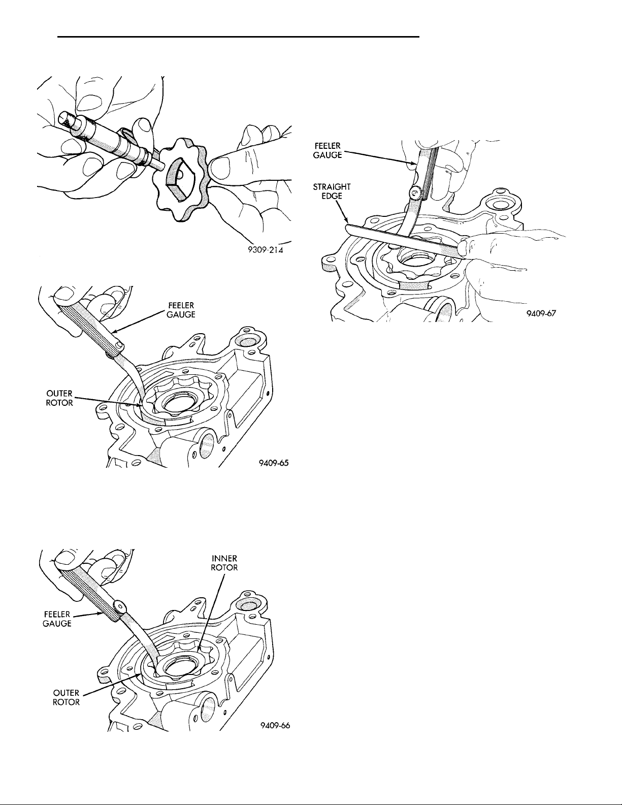
INNERROTOR OUTER ROTORFEELER GAUGE
FEELER GAUGEOUTER ROTOR
FEELERGAUGESTRAIGHTEDGE
PL 2.0L DOHC ENGINE 9 - 85
CLEANING AND INSPECTION (Continued)
(7) Place a straightedge across the face of the
pump housing, between bolt holes. If a feeler gauge
of .102 mm (.004 inch) or more can be inserted
between rotors and the straightedge, replace pump
assembly (Fig. 106). ONLY if rotors are in specs.
Fig. 98 Measuring Inner Rotor Thickness
Fig. 99 Measuring Outer Rotor Clearance in
Housing
(6) Install inner rotor into pump housing. If clearance between inner and outer rotors (Fig. 105) is .203
mm (.008 inch) or more, replace both rotors.
Fig. 100 Measuring Clearance Between Rotors
Fig. 101 Measuring Clearance Over Rotors
(8) Inspect oil pressure relief valve plunger for
scoring and free operation in its bore. Small marks
may be removed with 400-grit wet or dry sandpaper.
(9) The relief valve spring has a free length of
approximately 60.7 mm (2.39 inches) it should test
between 18 and 19 pounds when compressed to 40.5
mm (1.60 inches). Replace spring that fails to meet
specifications.
(10) If oil pressure is low and pump is within specifications, inspect for worn engine bearings, damaged
or missing oil pick-up tube o-ring, clogged oil pick-up
tube screen, clogged oil filter and stuck open pressure relief valve or other reasons for oil pressure
loss.
CYLINDER BLOCK AND BORE
(1) Clean cylinder block thoroughly and check all
core hole plugs for evidence of leaking.
(2) If new core plugs are installed, Refer to Engine
Core Plugs outlined in this section.
(3) Examine block and cylinder bores for cracks or
fractures.
CYLINDER BORE INSPECTION
The cylinder walls should be checked for out-ofround and taper with Tool C-119 (Fig. 107). The cylinder bore out-of-round is 0.050 mm (.002 inch)
maximum and cylinder bore taper is 0.051 mm (0.002
inch) maximum. If the cylinder walls are badly
scuffed or scored, the cylinder block should be
rebored and honed, and new pistons and rings fitted.
Whatever type of boring equipment is used, boring
and honing operation should be closely coordinated
with the fitting of pistons and rings in order that
Page 86
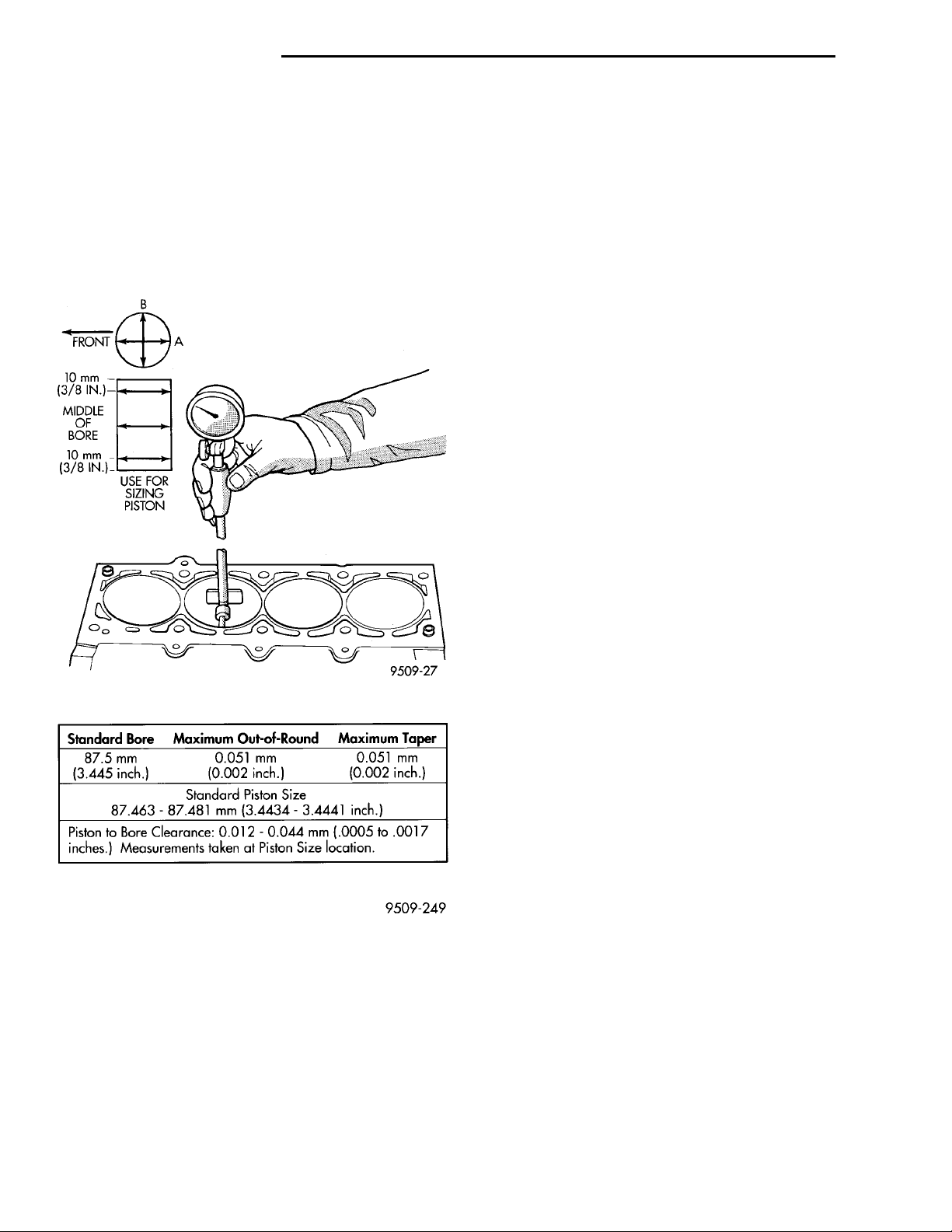
FRONT MIDDLEOF BORE
USE FOR
SIZING
PISTON
9 - 86 2.0L DOHC ENGINE PL
CLEANING AND INSPECTION (Continued)
specified clearances may be maintained. Refer to
Honing Cylinder Bores outlined in the Standard Service Procedures for specification and
procedures.
Measure the cylinder bore at three levels in directions A and B (Fig. 107). Top measurement should be
10 mm (3/8 inch) down and bottom measurement
should be 10 mm (3/8 inch.) up from bottom of bore.
Refer to (Fig. 108) for specifications.
Fig. 102 Checking Cylinder Bore Size
Fig. 103 Cylinder Bore and Piston Specifications
SPECIFICATIONS
ENGINE 2.0L DOHC
Cylinder Block
Cylinder Bore Diameter . . . 87.4924 - 87.5076 mm
(3.4446 - 3.4452 in.)
Out-of-Round (Max.) .......0.051 mm (0.002 in.)
Taper (Max.) .............0.051 mm (0.002 in.)
Pistons
Clearance 17.5 mm (11/16 in.)
from bottom of skirt ........0.018 - 0.050 mm
(0.0007 - 0.0020 in.)
Weight ......340-350grams (11.99 - 12.34 oz.)
Head Land Clearance
(Diametrical) .............0.740 - 0.803 mm
(0.029 - 0.031 in.)
Piston Length .............64.8 mm (2.551 in.)
Piston Ring Groove
Depth No. 1 ..............3.983 - 4.132 mm
(0.157 - 0.163 in.)
Piston Ring Groove
Depth No. 2 ..............4.456 - 4.605 mm
(0.175 - 0.181 in.)
Piston Ring Groove
Depth No. 3 ..............3.841 - 4.075 mm
(0.151 - 0.160 in.)
Piston Pins
Clearance in Piston ..........0.008 - 0.020 mm
(0.0003 - 0.0008 in.)
In Rod (Interference) .........0.018 - 0.043 mm
(0.0007 - 0.0017 in.)
Diameter ................20.998 - 21.003 mm
(0.8267 - 0.8269 in.)
End Play ............................None
Length ....................74.75 - 75.25 mm
(2.943 - 2.963 in.)
Piston Rings
Ring Gap Top
Compression Ring ...........0.23 - 0.52 mm
(0.009 - 0.020 in.)
Ring Gap 2nd
Compression Ring ...........0.49 - 0.78 mm
(0.019 - 0.031 in.)
Ring Gap Oil Control
(Steel Rails) ................0.23 - 0.66 mm
(0.009 - 0.026 in.)
Ring Side Clearance Both
Compression Rings ........0.025 - 0.065 mm
(0.0010 - 0.0026 in.)
Oil Ring (Pack) .............0.004 - 0.178 mm
(0.0002 - 0.0070 in.)
Ring Width Compression
Rings ......1.17 - 1.19 mm (0.046 - 0.047 in.)
Oil Ring (Pack) .............2.854 - 3.008 mm
(0.1124 - 0.1184 in.)
Page 87

PL 2.0L DOHC ENGINE 9 - 87
SPECIFICATIONS (Continued)
Connecting Rod
Bearing Clearance ...........0.026 - 0.059 mm
(0.001 - 0.0023 in.)
Piston Pin Bore Diameter .....20.96 - 20.98 mm
(0.8252 - 0.8260 in.)
Large End Bore Diameter . . . 50.991 - 51.005 mm
(2.0075 - 2.0081 in.)
Side Clearance ...............0.13 - 0.38 mm
(0.005 - 0.015 in.)
Total Weight
(Less Bearing) .........543grams (1.20 lbs.)
Crankshaft
Connecting Rod Journal
Diameter ............47.9924 - 48.0076 mm
(1.8894 - 1.8900 in.)
Out-of-Round (Max.) .....0.0035 mm (0.0001 in.)
Taper (Max.) ...........0.0038 mm (0.0001 in.)
Main Bearing Diametrical
Clearance No.1-5 ........0.022 - 0.062 mm
(0.0008 - 0.0024 in.)
End Play ....................0.09 - 0.24 mm
(0.0035 - 0.0094 in.)
Main Bearing Journals
Diameter ..............51.9924 - 52.0076 mm
(2.0469 - 2.0475 in.)
Out-of-Round (Max.) .....0.0035 mm (0.0001 in.)
Taper (Max.) ...........0.0038 mm (0.0001 in.)
Camshaft
Bearing Bore Diameter
No.1-6 ...........26.020 mm - 26.041 mm
(1.024 - 1.025 in.)
Diametrical Bearing
Clearance ...............0.069 - 0.071 mm
(0.0027 - 0.003 in.)
End Play ....................0.05 - 0.15 mm
(0.002 - 0.006 in.)
Bearing Journal Diameter
No.1-6...............25.951 - 25.970 mm
(1.021 - 1.022 in.)
Lift (Zero Lash) Intake ......8.75 mm (0.344 in.)
Lift (Zero Lash) Exhaust ....8.00 mm (0.314 in.)
Valve Timing @ .5 mm Lift
Intake Valve Closes (ABDC) ..............38°
Intake Valve Opens (BTDC) ..............1.2°
Intake Valve Duration ................219.2°
Exhaust Valve Closes (BTDC) ..............3°
Exhaust Valve Opens (BBDC) .............42°
Exhaust Valve Duration ................219°
Valve Overlap ..........................0°
Cylinder Head
Material ....................Cast Aluminum
Gasket Thickness
(Compressed) ...........1.15 mm (0.045 in.)
Valve Seat Angle ..................44.5 - 45°
Runout (Max.) ...........0.050 mm (0.002 in.)
Width (Finished) Intake
and Exhaust . . . 0.9 - 1.3 mm (0.035 - 0.051 in.)
Valve Guide Finished
Diameter ID .............5.975 - 6.000 mm
(0.235 - 0.236 in.)
Guide Bore Diameter
(Standard) ................11.0-11.02 mm
(0.4330 - 0.4338 in.)
Valves
Head Diameter Intake ........34.67 - 34.93 mm
(1.365 - 1.375 in.)
Head Diameter Exhaust ......30.37 - 30.36 mm
(1.195 - 1.195 in.)
Valve Margin Intake ...........1.15 - 1.48 mm
(0.0452 - 0.0582 in.)
Valve Margin Exhaust ........1.475 - 1.805 mm
(0.058 - 0.071 in.)
Length Intake .............111.49 -111.99 mm
(4.389 - 4.409 in.)
Length Exhaust ...........109.59 - 110.09 mm
(4.314 - 4.334 in.)
Valve Stem Tip
Heigth Intake ..........48.04 mm (1.891 in.)
Valve Stem Tip
Heigth Exhaust ........47.99 mm (1.889 in.)
Stem Diameter Intake .......5.9034 - 5.952 mm
(0.234 - 0.234 in.)
Stem Diameter Exhaust ......5.906 - 5.924 mm
(0.233 - 0.233 in.)
Stem-to-Guide Clearance
Intake ..................0.023 - 0.066 mm
(0.0009 - 0.0025 in.)
Stem-to-Guide Clearance
Exhaust .................0.051 - 0.094 mm
(0.002 - 0.0037 in.)
Maximum Allowable
Intake ................0.076 mm (0.003 in.)
Maximum Allowable
Exhaust ..............0.101 mm (0.004 in.)
Valve Spring
Free Length (Approx.) ........46mm(1.811 in.)
Spring Tension
(Valve Closed) ........246-270 N @ 38.0 mm
(55 - 60 lbs. @ 1.496 in.)
Spring Tension
(Valve Open) .........549-611 N @ 29.3 mm
(123 - 137 lbs. @ 1.53 in.)
Page 88
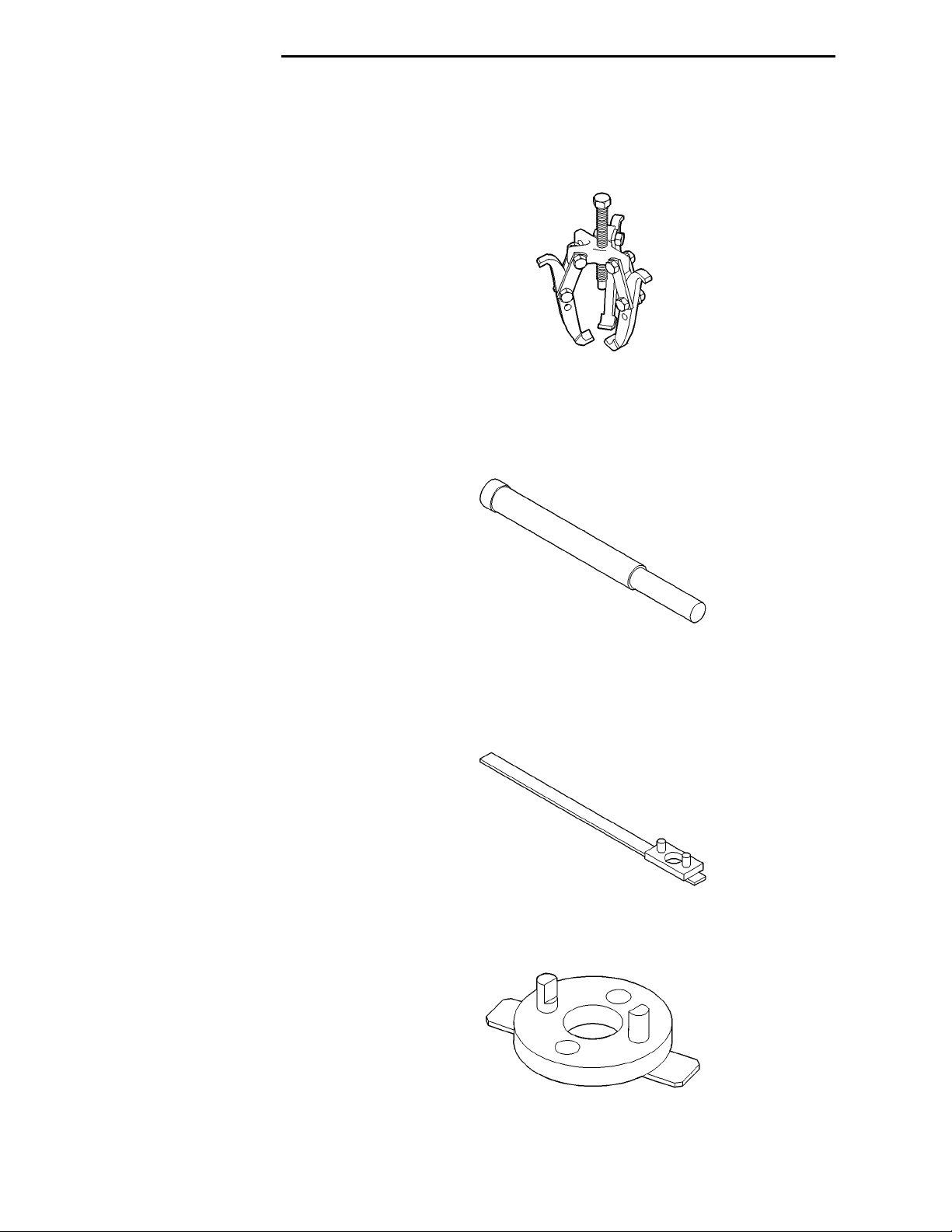
9 - 88 2.0L DOHC ENGINE PL
SPECIFICATIONS (Continued)
TORQUE CHART 2.0L DOHC
DESCRIPTION ...................TORQUE
Camshaft Sensor Pick-Up
Bolts ...................9.6N·m(85in.lbs.)
Timing Belt Cover
Bolts M6 ................12N·m(105 in. lbs.)
Camshaft Sprocket
Bolt ....................115N·m(85ft.lbs.)
Connecting Rod Cap
Bolts .........27N·m(20ft.lbs.) Plus 1/4 Turn
Crankshaft Main Bearing Cap/Bedplate
M8 Bedplate Bolts ..........30N·m(22ft.lbs.)
M11 Main Cap Bolts ........81N·m(60ft.lbs.)
Crankshaft Damper
Bolt ...................142N·m(105 ft. lbs.)
Cylinder Head
Bolts .......Refer To Cylinder Head Installation
Cylinder Head Cover
Bolts ...................12N·m(105 in. lbs.)
Engine Mount Bracket
Bolts ....................41N·m(30ft.lbs.)
Exhaust Manifold to Cylinder Head
Bolts ...................23N·m(200 in. lbs.)
Exhaust Manifold Heat Shield
Bolts ...................15N·m(130 in. lbs.)
Intake Manifold
Bolts ...................28N·m(250 in. lbs.)
Oil Filter Adapter
Fastener .................80N·m(60ft.lbs.)
Oil Filter .................20N·m(15ft.lbs.)
Oil Pan
Bolts ...................12N·m(105 in. lbs.)
Drain Plug ...............34N·m(25ft.lbs.)
Oil Pump Attaching
Bolts ...................28N·m(250 in. lbs.)
Oil Pump Cover Fastener . . . 12 N·m (105 in. lbs.)
Oil Pump Pick-up Tube Bolt . 28 N·m (250 in. lbs.)
Oil Pump Relief Valve Cap . . . 55 N·m (40 ft. lbs.)
Spark Plugs
Plug .....................28N·m(20ft.lbs.)
Thermostat Housing
Bolts ...................23N·m(200 in lbs.)
Timing Belt
Tensioner ...............28N·m(250 in. lbs.)
Timing Belt Tensioner Pulley Assembly Plate-
Backing
Bolts ....................41N·m(30ft.lbs.)
Timing Belt Tensioner Pulley
Bolt .......................68N·m(50ft.lbs.)
Water Pump Mounting
Bolts ...................12N·m(105 in. lbs.)
SPECIAL TOOLS
ENGINE 2.0L DOHC
Puller 1026
Crankshaft Damper Removal Insert 6827-A
Camshaft Sprocket Remover/Installer C-4687
Camshaft Sprocket Remover/Installer Adapter
C-4687-1
Page 89
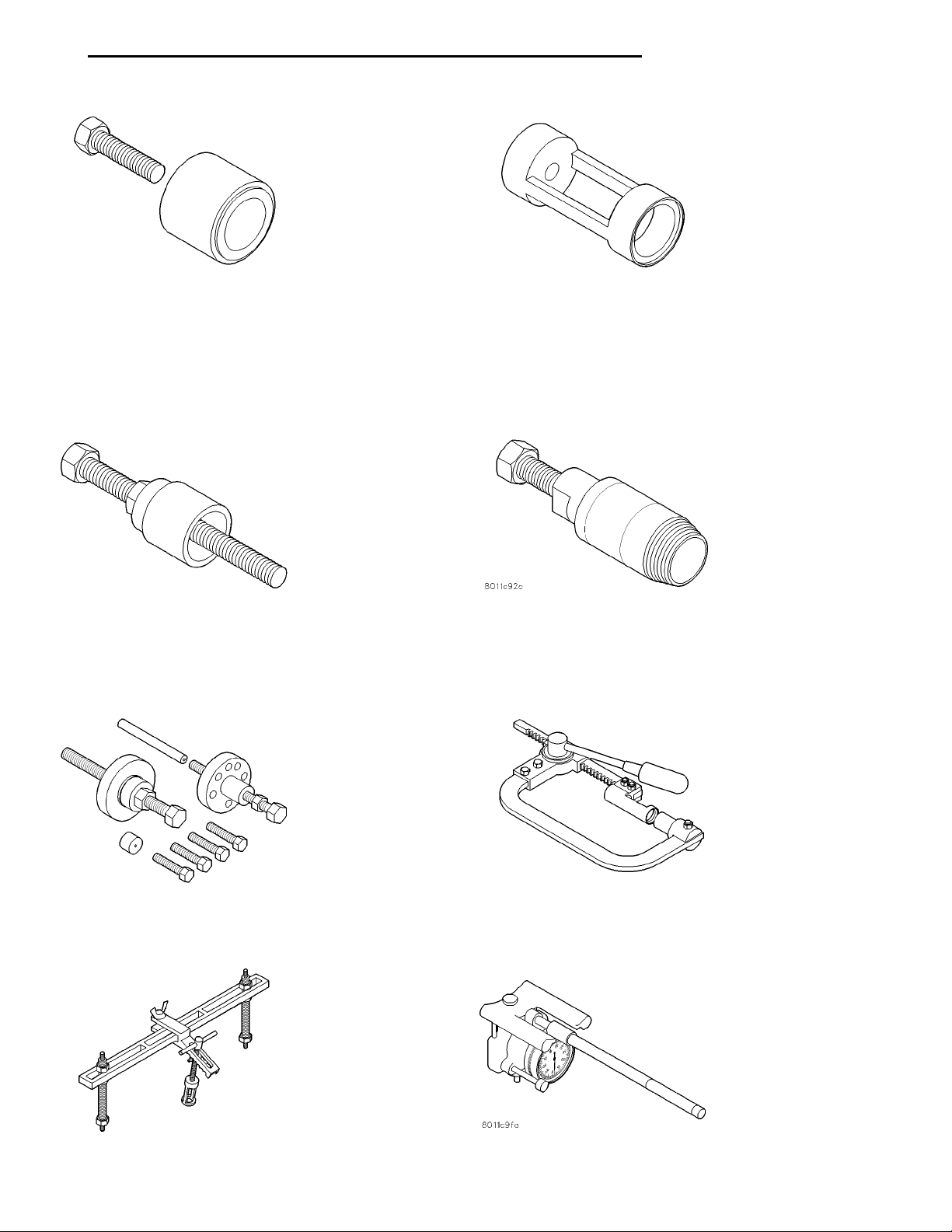
PL 2.0L DOHC ENGINE 9 - 89
SPECIAL TOOLS (Continued)
Camshaft Seal Installer MD-998713
Installer Crankshaft Damper 6792
Adapter Spring Compressor 6779
Front Crankshaft Seal Remover 6771
Installer Crankshaft Damper C-4685-C
Valve Spring Compressor MD-998772-A
Valve Spring Compressor C-3575-A
Cylinder Bore Indicator C-119
Page 90
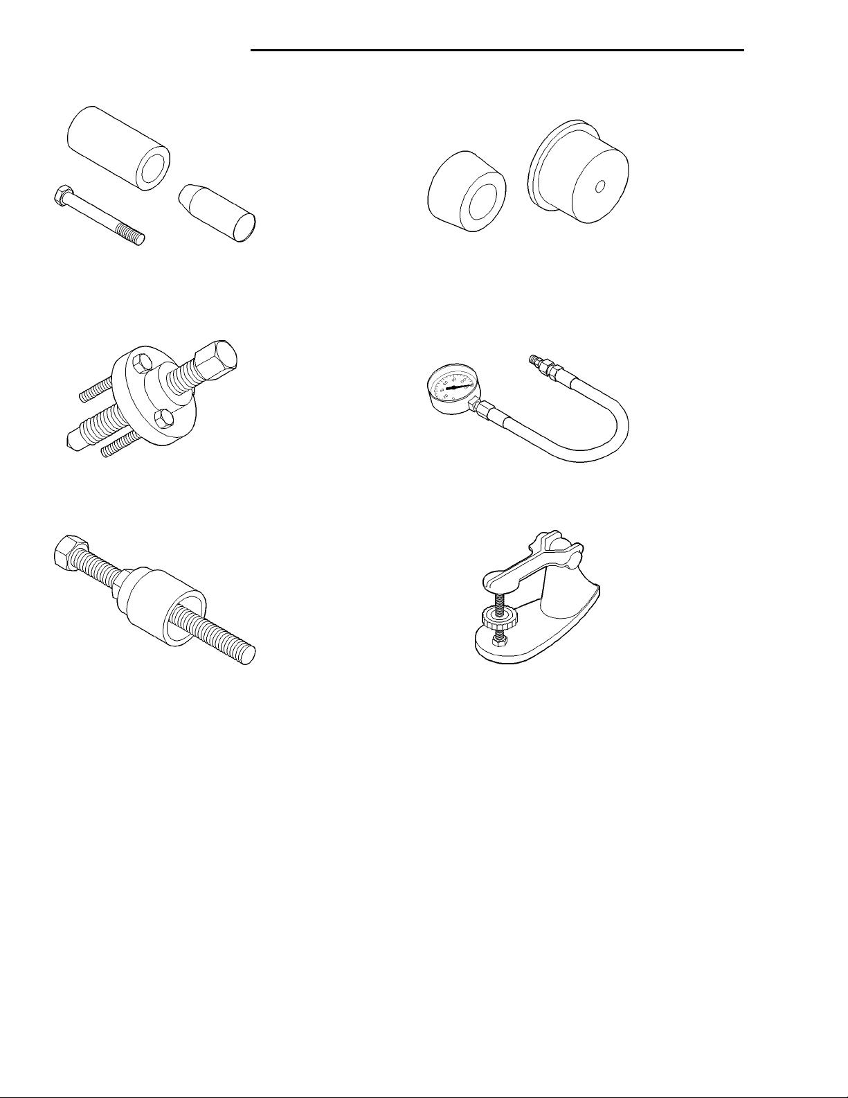
9 - 90 2.0L DOHC ENGINE PL
SPECIAL TOOLS (Continued)
Front Crankshaft Seal Installer 6780
Crankshaft Sprocket Remover 6793
Rear Crankshaft Seal Guide and Installer 6926-1 and
6926-2
Pressure Gage C-32932
Crankshaft Sprocket Installer 6792
Valve Spring Tester C-647
 Loading...