

Page 1

PL WIRING DIAGRAMS 8W - 1
WIRING DIAGRAMS
CONTENTS
page page
8W-01 GENERAL INFORMATION ....... 8W-01-1
8W-02 COMPONENT INDEX ........... 8W-02-1
8W-10 POWER DISTRIBUTION ........ 8W-10-1
8W-11 FUSE/FUSE BLOCK ............ 8W-11-1
8W-15 GROUND DISTRIBUTION ....... 8W-15-1
8W-20 CHARGING SYSTEM ........... 8W-20-1
8W-21 STARTING SYSTEM ........... 8W-21-1
8W-30 FUEL/IGNITION SYSTEMS ...... 8W-30-1
8W-35 ANTI-LOCK BRAKES ........... 8W-35-1
8W-40 INSTRUMENT CLUSTER ........ 8W-40-1
8W-41 HORNS/CIGAR LIGHTER ........ 8W-41-1
8W-42 AIR CONDITIONING-HEATER .... 8W-42-1
8W-43 AIRBAG SYSTEM ............. 8W-43-1
8W-44 INTERIOR LIGHTING ........... 8W-44-1
8W-47 AUDIO SYSTEMS ............. 8W-47-1
8W-48 REAR WINDOW DEFOGGER ..... 8W-48-1
8W-50 FRONT LIGHTING ............. 8W-50-1
8W-51 REAR LIGHTING .............. 8W-51-1
8W-52 TURN SIGNALS ............... 8W-52-1
8W-53 WIPERS ..................... 8W-53-1
8W-60 POWER WINDOWS ............ 8W-60-1
8W-61 POWER DOOR LOCKS ......... 8W-61-1
8W-62 POWER MIRRORS ............ 8W-62-1
8W-64 POWER SUNROOF ............ 8W-64-1
8W-70 SPLICE INFORMATION ......... 8W-70-1
8W-80 CONNECTOR PIN-OUTS ........ 8W-80-1
8W-90 CONNECTOR/GROUND
LOCATIONS ...................... 8W-90-1
8W-95 SPLICE LOCATIONS ........... 8W-95-1
Page 2

Page 3

PL 8W - 01 GENERAL INFORMATION 8W - 01 - 1
8W-01 GENERAL INFORMATION
INDEX
page page
DESCRIPTION AND OPERATION
CIRCUIT IDENTIFICATION ................. 3
CONNECTOR/GROUND LOCATIONS ......... 1
CONNECTORS .......................... 3
ELECTROSTATIC DISCHARGE (ESD)
SENSITIVE DEVICES .................... 5
FASTENERS ............................ 5
HOW TO USE THIS GROUP ................ 1
NOTES, CAUTIONS, and WARNINGS ......... 2
POSITIVE TEMPERATURE COEFFICIENT ..... 5
SECTION IDENTIFICATION ................. 1
SPLICE LOCATIONS ...................... 1
SYMBOLS .............................. 3
TAKE OUTS ............................ 3
WIRE CODE IDENTIFICATION .............. 2
DIAGNOSIS AND TESTING
CHECKING FOR TERMINAL SPREADING ...... 6
DESCRIPTION AND OPERATION
HOW TO USE THIS GROUP
The purpose of this group is to show the electrical
circuits in a clear, simple fashion and to make troubleshooting easier. Components that work together
are shown together. All electrical components used in
a specific system are shown on one diagram. The feed
for a system is shown at the top of the page. All
wires, connectors, splices, and components are shown
in the flow of current to the bottom of the page. Wiring which is not part of the circuit represented is referenced to another page/section, where the complete
circuit is shown. In addition, all switches, components, and modules are shown in the at rest posi-
tion with the doors closed and the key removed
from the ignition.
If a component is part of several different circuits,
it is shown in the diagram for each. For example, the
headlamp switch is the main part of the exterior
lighting, but it also affects the interior lighting and
the chime warning system. It is important to real-
ize that no attempt is made on the diagrams to
represent components and wiring as they
appear on the vehicle. For example, a short
piece of wire is treated the same as a long one.
In addition, switches and other components are
shown as simply as possible, with regard to
function only.
INTERMITTENT AND POOR CONNECTIONS . . . 6
TROUBLESHOOTING TESTS ............... 6
TROUBLESHOOTING TOOLS ............... 5
TROUBLESHOOTING WIRING PROBLEMS .... 7
SERVICE PROCEDURES
CONNECTOR AND TERMINAL REPLACEMENT . 9
CONNECTOR REPLACEMENT .............. 9
DIODE REPLACEMENT ................... 11
FUSIBLE LINK REPLACEMENT ............. 8
TERMINAL REPLACEMENT ............... 10
TERMINAL/CONNECTOR REPAIR-MOLEX
CONNECTORS ........................ 8
WIRING REPAIR ......................... 7
SPECIAL TOOLS
WIRING/TERMINAL ...................... 11
SECTION IDENTIFICATION
Sections in Group 8W are organized by sub-systems. The sections contain circuit operation descriptions, helpful information, and system diagrams. The
intention is to organize information by system, consistently from year to year.
CONNECTOR/GROUND LOCATIONS
Section 8W-90 contains connector/ground location
illustrations. The illustrations contain the connector
name (or number)/ground number and component
identification. Connector/ground location charts in
Section 8W-90 reference the illustration number for
components and connectors.
Section 8W-80 shows each connector and the circuits involved with that connector. The connectors
are identified using the name/number on the Diagram pages.
SPLICE LOCATIONS
Splice Location charts in Section 8W-70 show the
entire splice, and provide references to other sections
the splice serves.
Section 8W-95 contains illustrations that show the
general location of the splices in each harness. The
illustrations show the splice by number, and provide
a written location.
Page 4
8W - 01 - 2 8W - 01 GENERAL INFORMATION PL
DESCRIPTION AND OPERATION (Continued)
NOTES, CAUTIONS, and WARNINGS
Throughout this group additional important information is presented in three ways; Notes, Cautions,
and Warnings.
NOTES are used to help describe how switches or
components operate to complete a particular circuit.
They are also used to indicate different conditions
that may appear on the vehicle. For example, an
up-to and after condition.
CAUTIONS are used to indicate information that
could prevent making an error that may damage the
vehicle.
WARNINGS provide information to prevent personal injury and vehicle damage. Below is a list of
general warnings that should be followed any time a
vehicle is being serviced.
WARNING: ALWAYS WEAR SAFETY GLASSES FOR
EYE PROTECTION.
WARNING: USE SAFETY STANDS ANYTIME A PROCEDURE REQUIRES BEING UNDER A VEHICLE.
WARNING: ALWAYS REMOVE RINGS, WATCHES,
LOOSE HANGING JEWELRY, AND LOOSE CLOTHING.
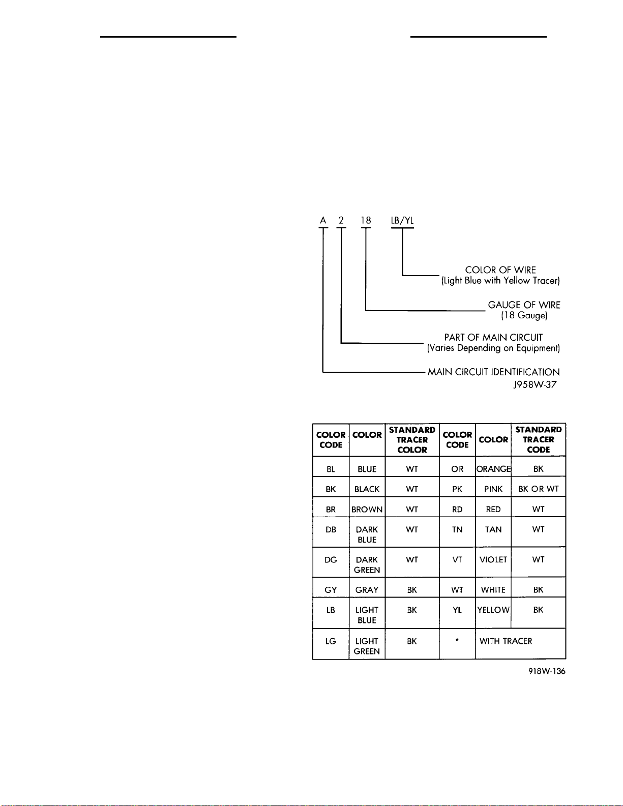
WIRE CODE IDENTIFICATION
Each wire shown in the diagrams contains a code
(Fig. 1) which identifies the main circuit, part of the
main circuit, gauge of wire, and color. The color is
shown as a two letter code which can be identified by
referring to the Wire Color Code Chart (Fig. 2)
WARNING: BE SURE THAT THE IGNITION SWITCH
ALWAYS IS IN THE OFF POSITION, UNLESS THE
PROCEDURE REQUIRES IT TO BE ON.
WARNING: SET THE PARKING BRAKE WHEN
WORKING ON ANY VEHICLE. AN AUTOMATIC
TRANSMISSION SHOULD BE IN PARK. A MANUAL
TRANSMISSION SHOULD BE IN NEUTRAL.
WARNING: OPERATE THE ENGINE ONLY IN A
WELL-VENTILATED AREA.
WARNING: KEEP AWAY FROM MOVING PARTS
WHEN THE ENGINE IS RUNNING, ESPECIALLY THE
FAN AND BELTS.
WARNING: TO PREVENT SERIOUS BURNS, AVOID
CONTACT WITH HOT PARTS SUCH AS THE RADIATOR, EXHAUST MANIFOLD(S), TAIL PIPE, CATALYTIC CONVERTER, AND MUFFLER.
Fig. 1 Wire Code Identification
WARNING: DO NOT ALLOW FLAME OR SPARKS
NEAR THE BATTERY. GASES ARE ALWAYS
PRESENT IN AND AROUND THE BATTERY.
Fig. 2 Wire Color Code Chart
Page 5
PL 8W - 01 GENERAL INFORMATION 8W - 01 - 3
DESCRIPTION AND OPERATION (Continued)
CIRCUIT IDENTIFICATION
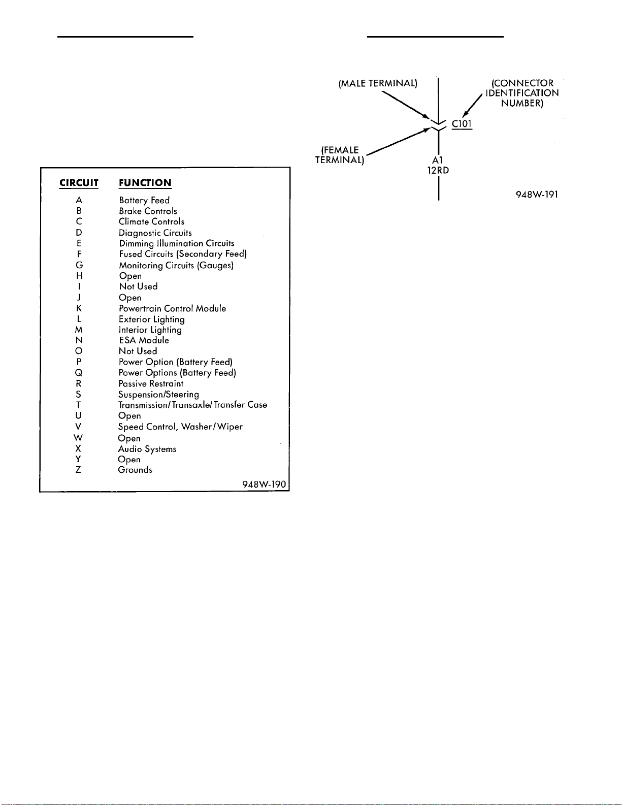
All circuits in the diagrams use an alpha/numeric
code to identify the wire and its function (Fig. 3). To
identify which circuit code applies to a system, refer
to the Circuit Identification Code Chart. This chart
shows the main circuits only and does not show the
secondary codes that may apply to some models.
Fig. 4 Connector Identification
For viewing connector pin outs, with two terminals
or greater, refer to section 8W-80. This section identifies in-line connectors by number, and component
connectors by name. If a component has two or more
connectors they will be identified as C1, C2, C3...etc.
This sections also provides terminal numbering, circuit identification, wire colors, and functions.
All connectors are viewed from the terminal end
unless otherwise specified. To find the connector location in the vehicle refer to section 8W-90. This section uses the connector identification number from
the wiring diagrams to provide a figure number reference.
Fig. 3 Circuit Identification
CONNECTORS
Connectors shown in the diagrams are identified
using the international standard arrows for male and
female terminals (Fig. 4). A connector identifier is
placed next to the arrows to indicate the connector
number (Fig. 4).
TAKE OUTS
The abbreviation T/O is used in the component
location section to indicate a point in which the wiring harness branches out to a component.
SYMBOLS
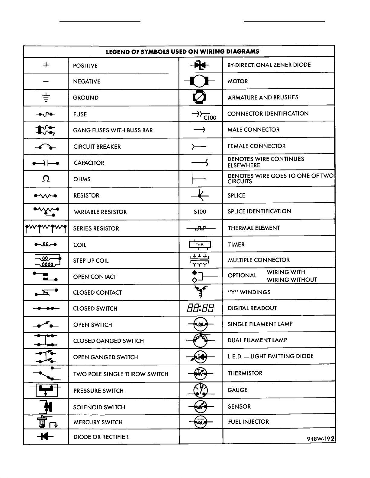
Various symbols are used throughout the Wiring
Diagrams. These symbols can be identified by referring to the symbol identification chart (Fig. 5).
Page 6
8W - 01 - 4 8W - 01 GENERAL INFORMATION PL
DESCRIPTION AND OPERATION (Continued)
Fig. 5 Symbol Identification
Page 7
PL 8W - 01 GENERAL INFORMATION 8W - 01 - 5
DESCRIPTION AND OPERATION (Continued)
ELECTROSTATIC DISCHARGE (ESD) SENSITIVE DEVICES
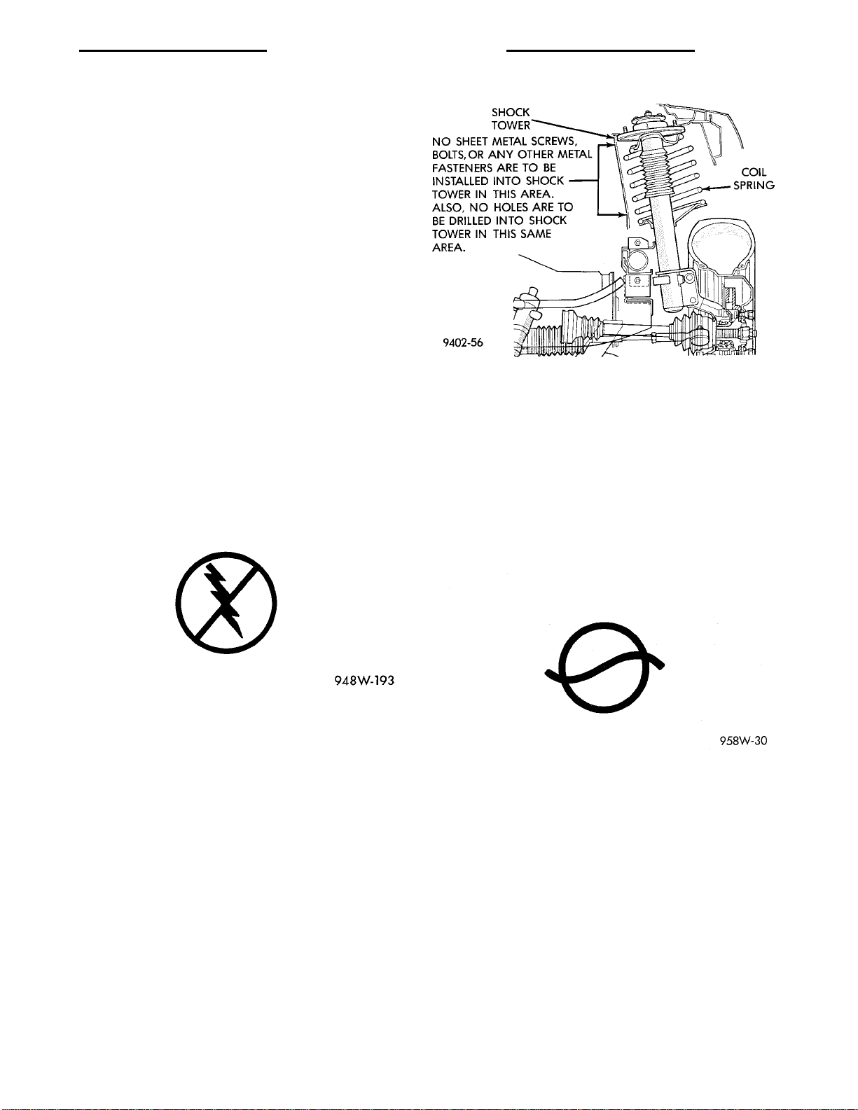
All ESD sensitive components are solid state and a
symbol (Fig. 6) is used to indicate this. When handling any component with this symbol comply with
the following procedures to reduce the possibility of
electrostatic charge build up on the body and inadvertent discharge into the component. If it is not
known whether the part is ESD sensitive, assume
that it is.
(1) Always touch a known good ground before handling the part. This should be repeated while handling the part and more frequently after sliding
across a seat, sitting down from a standing position,
or walking a distance.
(2) Avoid touching electrical terminals of the part,
unless instructed to do so by a written procedure.
(3) When using a voltmeter, be sure to connect the
ground lead first.
(4) Do not remove the part from its protective
packing until it is time to install the part.
(5) Before removing the part from its package,
ground the package to a known good ground on the
vehicle.
Fig. 7 Shock Tower to Spring Minimum Clearance
Area
POSITIVE TEMPERATURE COEFFICIENT
Positive Temperature Coefficient (PTC) devices are
being used for circuit protection. These PTC’s act like
a solid state fuse. They are located in the junction
block, and are used to protect such items as: power
door lock motors, power windows, and various engine
solenoids.
A special symbol is used to identify these in the
wiring diagrams (Fig. 8).
Fig. 6 Electrostatic Discharge Symbol
FASTENERS
CAUTION: At no time when servicing a vehicle, can
a sheet metal screw, bolt, or other metal fastener be
installed in the strut tower to take the place of an
original plastic clip. Also, NO holes can be drilled
into the front strut tower in the area shown in (Fig.
7) for the installation of any metal fasteners into the
strut tower. Because of the minimum clearance in
this area (Fig. 7) installation of metal fasteners
could damage the coil spring coating and lead to a
corrosion failure of the spring. If a plastic clip is
missing, or is lost or broken during servicing a
vehicle, replace only with the equivalent part listed
in the parts catalog.
Fig. 8 Positive Temperature Coefficient Symbol
DIAGNOSIS AND TESTING
TROUBLESHOOTING TOOLS
When diagnosing a problem in an electrical circuit
there are several common tools necessary. These tools
are listed and explained below.
• Jumper Wire - This is a test wire used to connect two points of a circuit. It can be used to bypass
an open in a circuit.
WARNING: NEVER USE A JUMPER WIRE ACROSS
A LOAD, SUCH AS A MOTOR, CONNECTED
BETWEEN A BATTERY FEED AND GROUND.
Page 8
8W - 01 - 6 8W - 01 GENERAL INFORMATION PL
DIAGNOSIS AND TESTING (Continued)
• Voltmeter - Used to check for voltage on a circuit. Always connect the black lead to a known good
ground and the red lead to the positive side of the
circuit.
CAUTION: Most of the electrical components used
in today’s vehicle are solid state. When checking
voltages in these circuits use a meter with a 10-megohm or greater impedance.
• Ohmmeter - Used to check the resistance
between two points of a circuit. Low or no resistance
in a circuit means good continuity.
CAUTION: - Most of the electrical components used
in today’s vehicle are Solid State. When checking
resistance in these circuits use a meter with a
10-megohm or greater impedance. In addition, make
sure the power is disconnected from the circuit.
Circuits that are powered up by the vehicle electrical system can cause damage to the equipment and
provide false readings.
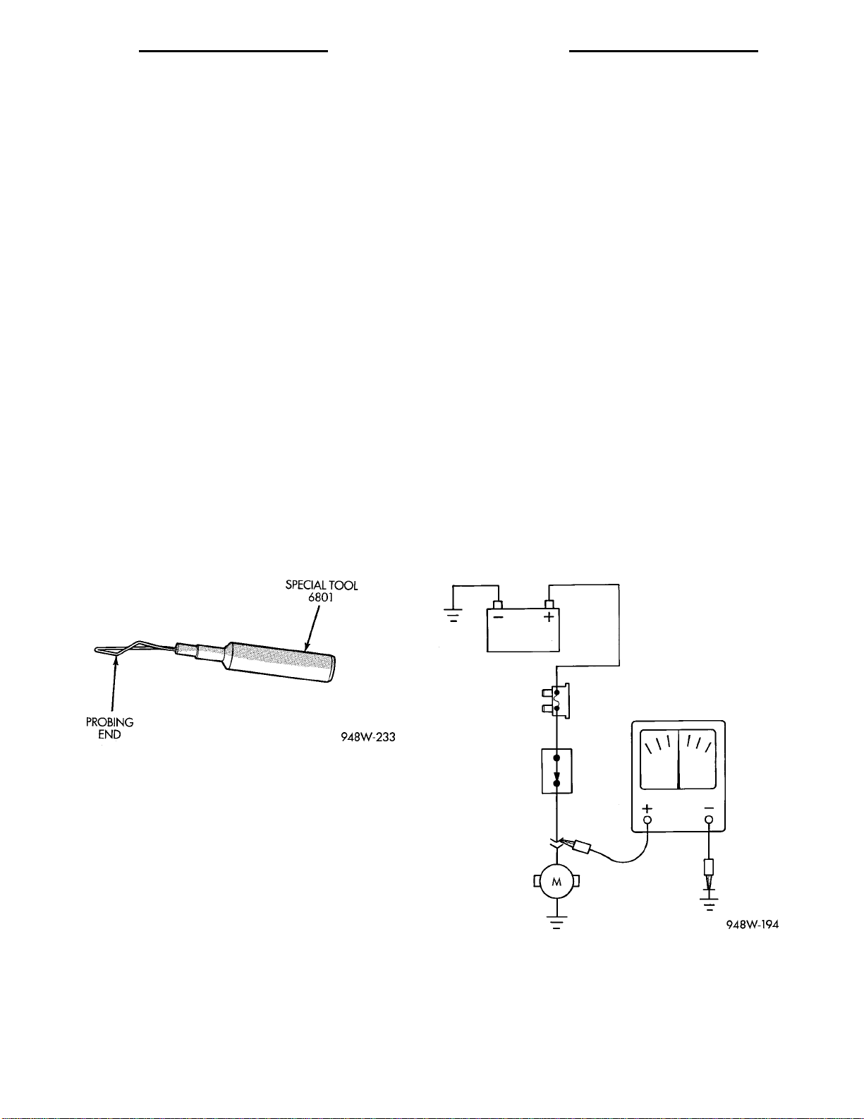
• Probing Tools - These tools are used for probing
terminals in connectors (Fig. 9). Select the proper
size tool from Special Tool Package 6807, and insert
it into the terminal being tested. Use the other end
of the tool to insert the meter probe.
• Wire insulation that has rubbed through causing
a short to ground
• Wiring broke inside of the insulation
CHECKING FOR TERMINAL SPREADING
When an intermittent or open circuit is suspected
it is important to check for a spread terminal. To
accomplish this remove the suspect female terminal
from its connector.
Check the female terminal for drag when mated
with the appropriate male terminal. If the terminal
is spread (no or little drag felt) replace the terminal
using the procedures covered in this section of the
wiring diagrams.
TROUBLESHOOTING TESTS
Before beginning any tests on a vehicles electrical
system use the Wiring Diagrams and study the circuit. Also refer to the Troubleshooting Wiring Problems section in this section.
TESTING FOR VOLTAGE
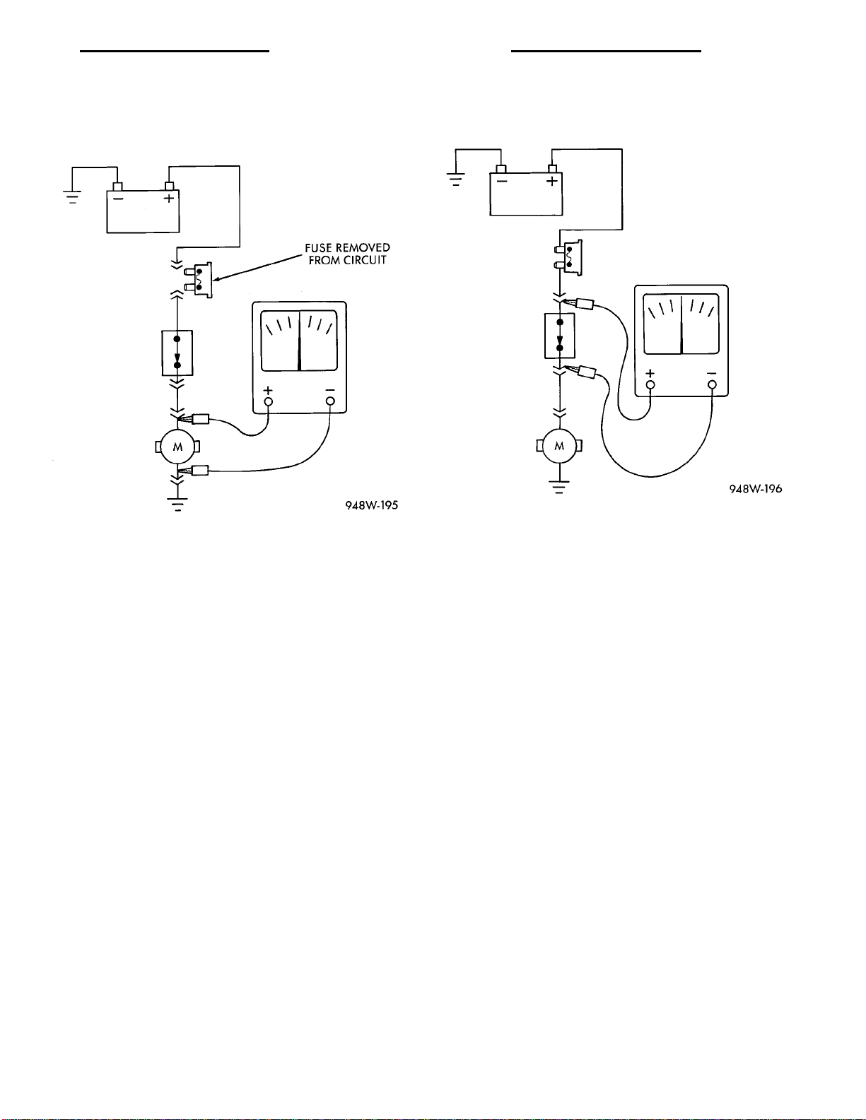
(1) Connect the ground lead of a voltmeter to a
known good ground (Fig. 10).
(2) Connect the other lead of the voltmeter to the
selected test point. The vehicle ignition may need to
be turned ON to check voltage. Refer to the appropriate test procedure.
Fig. 9 Probing Tool
INTERMITTENT AND POOR CONNECTIONS
Most intermittent electrical problems are caused
by faulty electrical connections or wiring. It is also
possible for a sticking component or relay to cause a
problem. Before condemning a component or wiring
assembly check the following items.
• Connectors are fully seated
• Spread terminals, or terminal push out
• Terminals in the wiring assembly are fully
seated into the connector/component and locked in
position
• Dirt or corrosion on the terminals. Any amount
of corrosion or dirt could cause an intermittent problem
• Damaged connector/component casing exposing
the item to dirt and moisture
Fig. 10 Testing for Voltage
TESTING FOR CONTINUITY
(1) Remove the fuse for the circuit being checked
or, disconnect the battery.
(2) Connect one lead of the ohmmeter to one side
of the circuit being tested (Fig. 11).
Page 9
PL 8W - 01 GENERAL INFORMATION 8W - 01 - 7
DIAGNOSIS AND TESTING (Continued)
(3) Connect the other lead to the other end of the
circuit being tested. Low or no resistance means good
continuity.
(4) The voltmeter will show the difference in volt-
age between the two points.
Fig. 11 Testing for Continuity
TESTING FOR A SHORT TO GROUND
(1) Remove the fuse and disconnect all items
involved with the fuse.
(2) Connect a test light or a voltmeter across the
terminals of the fuse.
(3) Starting at the fuse block, wiggle the wiring
harness about six to eight inches apart and watch
the voltmeter/test lamp.
(4) If the voltmeter registers voltage or the test
lamp glows, there is a short to ground in that general area of the wiring harness.
TESTING FOR A SHORT TO GROUND ON FUSES POWERING SEVERAL LOADS
(1) Refer to the wiring diagrams and disconnect or
isolate all items on the fused circuit.
(2) Replace the blown fuse.
(3) Supply power to the fuse by turning ON the
ignition switch or re-connecting the battery.
(4) Start connecting the items in the fuse circuit
one at a time. When the fuse blows the circuit with
the short to ground has been isolated.
TESTING FOR A VOLTAGE DROP
(1) Connect the positive lead of the voltmeter to
the side of the circuit closest to the battery (Fig. 12).
(2) Connect the other lead of the voltmeter to the
other side of the switch or component.
(3) Operate the item.
Fig. 12 Testing for Voltage Drop
TROUBLESHOOTING WIRING PROBLEMS
When troubleshooting wiring problems there are
six steps which can aid in the procedure. The steps
are listed and explained below. Always check for nonfactory items added to the vehicle before doing any
diagnosis. If the vehicle is equipped with these items,
disconnect them to verify these add-on items are not
the cause of the problem.
(1) Verify the problem.
(2) Verify any related symptoms. Do this by performing operational checks on components that are
in the same circuit. Refer to the wiring diagrams.
(3) Analyze the symptoms. Use the wiring diagrams to determine what the circuit is doing, where
the problem most likely is occurring and where the
diagnosis will continue.
(4) Isolate the problem area.
(5) Repair the problem.
(6) Verify proper operation. For this step check for
proper operation of all items on the repaired circuit.
Refer to the wiring diagrams.
SERVICE PROCEDURES
WIRING REPAIR
When replacing or repairing a wire, it is important
that the correct gauge be used as shown in the wiring diagrams. The wires must also be held securely
in place to prevent damage to the insulation.
(1) Disconnect battery negative cable
Page 10
8W - 01 - 8 8W - 01 GENERAL INFORMATION PL
SERVICE PROCEDURES (Continued)
(2) Remove 1 inch of insulation from each end of
the wire.
(3) Place a piece of heat shrink tubing over one
side of the wire. Make sure the tubing will be long
enough to cover and seal the entire repair area.
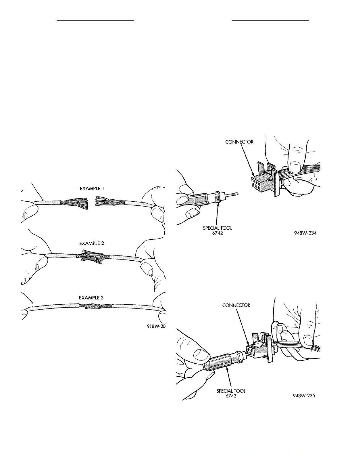
(4) Spread the strands of the wire apart on each
part of the exposed wire (example 1). (Fig. 13)
(5) Push the two ends of wire together until the
strands of wire are close to the insulation (example
2) (Fig. 13)
(6) Twist the wires together (example 3) (Fig. 13)
(7) Solder the connection together using rosin core
type solder only. Do not use acid core solder.
(8) Center the heat shrink tubing over the joint,
and heat using a heat gun. Heat the joint until the
tubing is tightly sealed and sealant comes out of both
ends of the tubing.
(9) Secure the wire to the existing ones to prevent
chafing or damage to the insulation
(10) Connect battery and test all affected systems.
ment this indicates a problem in the charging/starting system that needs to be corrected.
Replacement of the fusible link is the same as
repairing a wire. Refer to the wiring repair information in this section for soldering information.
TERMINAL/CONNECTOR REPAIR-MOLEX CONNECTORS
(1) Disconnect battery.
(2) Disconnect the connector from its mating half/
component.
(3) Insert the terminal releasing special tool 6742
into the terminal end of the connector (Fig. 14).
Fig. 13 Wire Repair
FUSIBLE LINK REPLACEMENT
On PL vehicles there is a fusible link placed
between the output terminal of the generator and the
engine starter motor terminal. A service part is available if this fusible link requires replacement.
This service part has the eyelet that attaches to
the starter motor. If the fusible link requires replace-
Fig. 14 Molex Connector Repair
(4) Using special tool 6742 release the locking fin-
gers on the terminal (Fig. 15).
(5) Pull on the wire to remove it from the connec-
tor.
(6) Repair or replace the connector or terminal, as
necessary.
Fig. 15 Using Special Tool 6742
Page 11
PL 8W - 01 GENERAL INFORMATION 8W - 01 - 9
SERVICE PROCEDURES (Continued)
CONNECTOR REPLACEMENT
(1) Disconnect battery.
(2) Disconnect the connector that is to be repaired
from its mating half/component
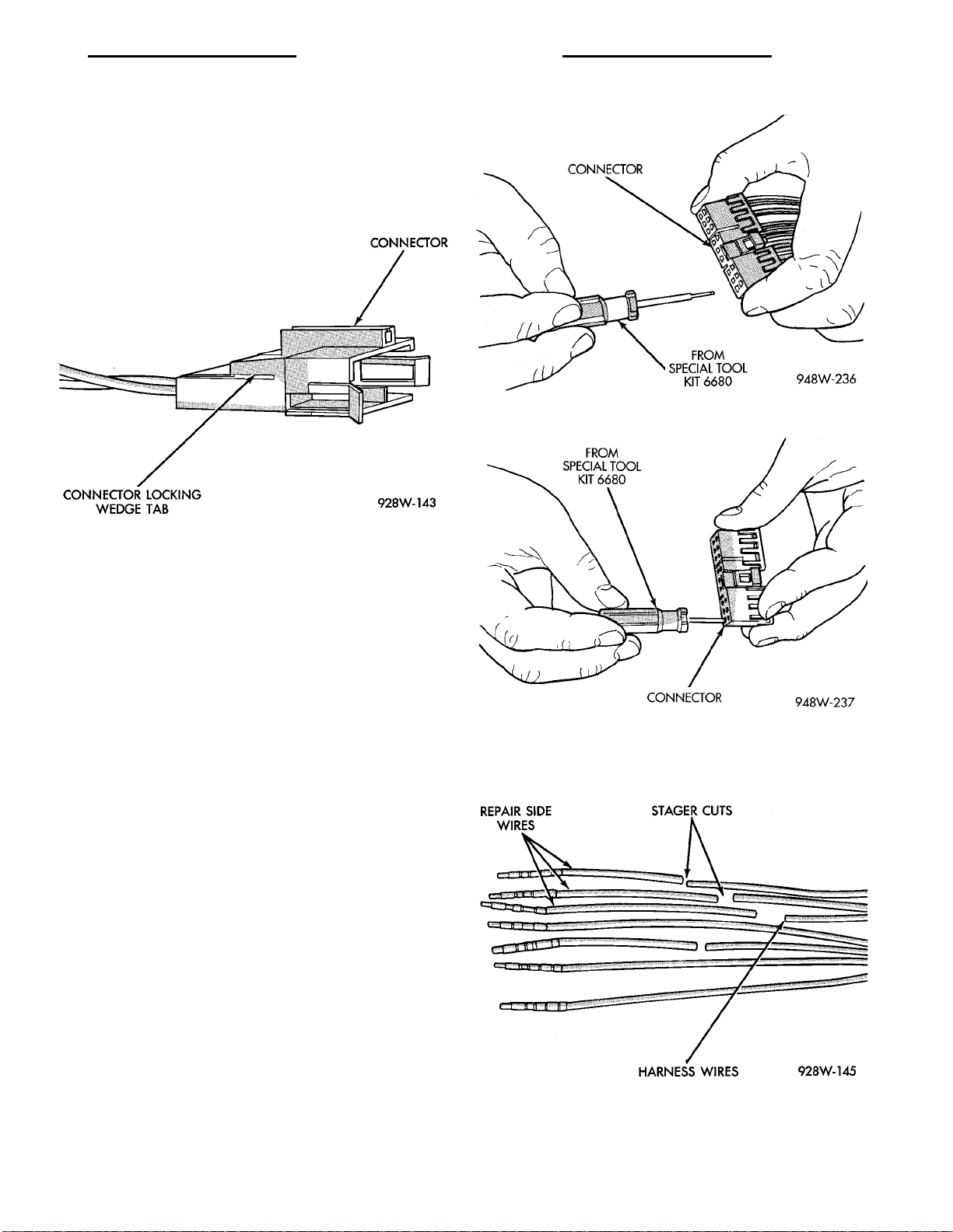
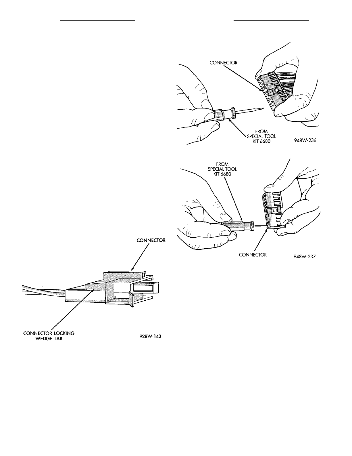
(3) Remove the connector locking wedge, if
required (Fig. 16)
Fig. 17 Terminal Removal
Fig. 16 Connector Locking Wedge
(4) Position the connector locking finger away from
the terminal using the proper pick from special tool
kit 6680. Pull on the wire to remove the terminal
from the connector (Fig. 17) (Fig. 18).
(5) Reset the terminal locking tang, if it has one.
(6) Insert the removed wire in the same cavity on
the repair connector.
(7) Repeat steps four through six for each wire in
the connector, being sure that all wires are inserted
into the proper cavities. For additional connector pinout identification, refer to the wiring diagrams.
(8) Insert the connector locking wedge into the
repaired connector, if required.
(9) Connect connector to its mating half/component.
(10) Connect battery and test all affected systems.
CONNECTOR AND TERMINAL REPLACEMENT
(1) Disconnect battery.
(2) Disconnect the connector (that is to be
repaired) from its mating half/component.
(3) Cut off the existing wire connector directly
behind the insulator. Remove six inches of tape from
the harness.
(4) Stagger cut all wires on the harness side at
1/2 inch intervals (Fig. 19).
(5) Remove 1 inch of insulation from each wire on
the harness side.
(6) Stagger cut the matching wires on the repair
connector assembly in the opposite order as was done
on the harness side of the repair. Allow extra length
Fig. 18 Terminal Removal Using Special Tool
for soldered connections. Check that the overall
length is the same as the original (Fig. 19).
Fig. 19 Stagger Cutting Wires
(7) Remove 1 inch of insulation from each wire.
Page 12
8W - 01 - 10 8W - 01 GENERAL INFORMATION PL
SERVICE PROCEDURES (Continued)
(8) Place a piece of heat shrink tubing over one
side of the wire. Be sure the tubing will be long
enough to cover and seal the entire repair area.
(9) Spread the strands of the wire apart on each
part of the exposed wires.
(10) Push the two ends of wire together until the
strands of wire are close to the insulation.
(11) Twist the wires together.
(12) Solder the connection together using rosin
core type solder only. Do not use acid core solder.
(13) Center the heat shrink tubing over the joint
and heat using a heat gun. Heat the joint until the
tubing is tightly sealed and sealant comes out of both
ends of the tubing
(14) Repeat steps 8 through 13 for each wire.
(15) Re-tape the wire harness starting 1-1/2 inches
behind the connector and 2 inches past the repair.
(16) Re-connect the repaired connector.
(17) Connect the battery, and test all affected systems.
Fig. 21 Terminal Removal
TERMINAL REPLACEMENT
(1) Disconnect battery.
(2) Disconnect the connector being repaired from
its mating half. Remove connector locking wedge, if
required (Fig. 20).
(3) Remove connector locking wedge, if required
(Fig. 20).
Fig. 20 Connector Locking Wedge Tab (Typical)
(4) Position the connector locking finger away
from the terminal using the proper pick from special
tool kit 6680. Pull on the wire to remove the terminal
from the connector (Fig. 21) (Fig. 22).
(5) Cut the wire 6 inches from the back of the
connector.
(6) Remove 1 inch of insulation from the wire on
the harness side.
(7) Select a wire from the terminal repair assembly that best matches the color wire being repaired.
Fig. 22 Terminal Removal Using Special Tool
(8) Cut the repair wire to the proper length and
remove 1 inch of insulation.
(9) Place a piece of heat shrink tubing over one
side of the wire. Make sure the tubing will be long
enough to cover and seal the entire repair area.
(10) Spread the strands of the wire apart on each
part of the exposed wires.
(11) Push the two ends of wire together until the
strands of wire are close to the insulation.
(12) Twist the wires together.
(13) Solder the connection together using rosin
core type solder only. Do not use acid core solder.
(14) Center the heat shrink tubing over the joint
and heat using a heat gun. Heat the joint until the
tubing is tightly sealed and sealant comes out of both
ends of the tubing.
(15) Insert the repaired wire into the connector.
(16) Install the connector locking wedge, if
required, and reconnect the connector to its mating
half/component.
(17) Re-tape the wire harness starting 1-1/2 inches
behind the connector and 2 inches past the repair.
(18) Connect battery, and test all affected systems.
Page 13
PL 8W - 01 GENERAL INFORMATION 8W - 01 - 11
SERVICE PROCEDURES (Continued)
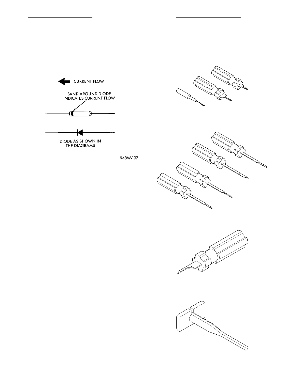
DIODE REPLACEMENT
(1) Disconnect the battery.
(2) Locate the diode in the harness, and remove
the protective covering.
(3) Remove the diode from the harness, pay atten-
tion to the current flow direction (Fig. 23).
Probing Tool Package 6807
Fig. 23 Diode Identification
(4) Remove the insulation from the wires in the
harness. Only remove enough insulation to solder in
the new diode.
(5) Install the new diode in the harness, making
sure current flow is correct. If necessary refer to the
appropriate wiring diagram for current flow.
(6) Solder the connection together using rosin core
type solder only. Do not use acid core solder.
(7) Tape the diode to the harness using electrical
tape making, sure the diode is completely sealed
from the elements.
(8) Re-connect the battery, and test affected systems.
SPECIAL TOOLS
WIRING/TERMINAL
Terminal Pick 6680
Terminal Removing Tool 6932
Terminal Removing Tool 6934
Page 14

Page 15

PL 8W - 02 COMPONENT INDEX 8W - 02 - 1
8W-02 COMPONENT INDEX
INDEX
page
SCHEMATICS AND DIAGRAMS ........................................................... 1
GENERAL INFORMATION ................................................................ 3
Component Page
A/C Compressor Clutch .................8W-42
A/C Compressor Clutch Relay ............8W-42
A/C Cycling Switch ....................8W-42
A/C Heater Blower Motor ................8W-42
A/C Heater Control Switch ...............8W-42
A/C High Pressure Switch ...............8W-42
A/C Low Pressure Switch ................8W-42
ABS Hydraulic Modulator ...............8W-35
ABS Pump Motor ......................8W-35
ABS Pump Motor Relay .................8W-35
ABS Relay Box ........................8W-35
ABS System Relay .....................8W-35
ABS Warning Lamp ....................8W-35
Airbag Control Module ..................8W-43
Airbag Impact Sensors ..................8W-43
Airbag Warning Lamp ..................8W-40
Antenna .............................8W-47
Anti-Lock Warning Lamp ................8W-40
Ash Receiver Lamp ....................8W-44
Automatic Shut Down Relay .............8W-30
Back-Up Lamp Switch ..................8W-51
Back-Up Lamps .......................8W-51
Battery ..............................8W-20
Battery Temperature Sensor .............8W-30
Blower Motor Resistor Block .............8W-42
Brake Warning Lamp ...................8W-40
Brake Warning Lamp Switch .............8W-40
Camshaft Position (CMP) Sensor ..........8W-30
Capacitor .........................8W-10, 20
Charge Indicator Lamp .................8W-40
Check Engine Lamp ....................8W-40
Cigar Lighter/Power Outlet ..............8W-41
Circuit Breaker (FB) ...................8W-11
Clockspring ..........................8W-41
Cluster Illumination Lamps ..............8W-40
Clutch Pedal Position Switch ..........8W-10, 21
Combination Flasher ...................8W-52
Controller Anti-Lock Brake ..............8W-35
Crankshaft Position (CKP) Sensor .........8W-30
Data Link Connector ...................8W-30
Diode No. 1 ........................8W-11,44
Diode No. 2 ........................8W-15, 42
Dome Lamp ..........................8W-44
Door Ajar Switches .....................8W-44
Door Jamb Switches ....................8W-40
Component Page
Door Lock Motors ......................8W-61
Door Lock Switches ....................8W-61
Door Speakers ........................8W-47
Driver Side Airbag .....................8W-43
Duty Cycle Evap/Purge Solenoid ..........8W-30
EGR Transducer Solenoid ...............8W-30
Engine Coolant Temperature (ECT) Sensor . . 8W-30
Engine Coolant Temperature Gauge .......8W-40
Engine Oil Pressure Switch ..............8W-40
Engine Starter Motor ...................8W-21
Engine Starter Motor Relay ..............8W-21
Fog Lamp Relay ....................8W-50, 51
Fog Lamps ........................8W-50, 51
Front Fog Lamp Switch .................8W-50
Fuel Gauge ...........................8W-40
Fuel Injectors .........................8W-30
Fuel Pump Module .....................8W-30
Fuel Pump Relay ......................8W-30
Fuse Block ...........................8W-11
Fuses (FB) ...........................8W-11
Fuses (PDC) ..........................8W-10
Fusible Link .......................8W-20, 21
Generator ............................8W-20
Glove Box Lamp And Switch .............8W-44
Ground Distribution ....................8W-15
Halo Lamp ...........................8W-44
Headlamp Dimmer And Optical
Horn Switch ........................8W-50
Headlamp Leveling Motors ..............8W-50
Headlamp Leveling Switch ...............8W-50
Headlamp Switch ......................8W-50
Headlamps ...........................8W-50
Heated Oxygen Sensors .................8W-30
High Beam Indicator Lamp ..............8W-40
Horn Relay ...........................8W-41
Horn Switches ........................8W-41
Horns ...............................8W-41
IAT/MAP Sensor ......................8W-30
Idle Air Control (IAC) Motor .............8W-30
Ignition Coil Pack .....................8W-30
Ignition Switch ........................8W-10
Immobilizer Engine Sensor ..............8W-30
Immobilizer Sensor ....................8W-30
Instrument Cluster ....................8W-40
Instrument Panel Speakers ..............8W-47
Page 16

8W - 02 - 2 8W - 02 COMPONENT INDEX PL
Component Page
Intermittent Wipe/Wash Switch ...........8W-53
Key-In Switch ........................8W-40
Knock Sensor .........................8W-30
License Lamps ........................8W-51
Low Oil Pressure Lamp .................8W-40
Map/Reading Lamps ...................8W-44
Master Power Window Switch ............8W-60
Mercury Switch .......................8W-44
Noise Supressor .......................8W-30
Park Brake Switch .....................8W-40
Park/Neutral Position Switch .............8W-51
Park/Turn Signal Lamps ................8W-52
Passenger Side Airbag ..................8W-43
Power Distribution Center ...............8W-10
Power Mirror Motors ...................8W-62
Power Mirror Switch ...................8W-62
Power Steering Pressure Switch ..........8W-30
Power Sunroof Motor ...................8W-64
Power Window Motors ..................8W-60
Power Window Switches .................8W-60
Powertrain Control Module ..............8W-30
PRNDL Lamp ........................8W-44
Pump Motor Driver ....................8W-35
Radiator Fan Motor ....................8W-42
Radio ...............................8W-47
Rear Fog Lamp Switch ..................8W-51
Rear Window Defogger ..................8W-48
Rear Window Defogger Switch ............8W-48
Component Page
Repeater Lamps ....................8W-50, 52
Seat Belt Warning Lamp ................8W-40
Solid State Fan Relay ..................8W-42
Speakers ............................8W-47
Splice Information .....................8W-30
Stop Lamp Switch .....................8W-30
Sunroof Slide Switch ...................8W-64
Sunroof Vent Switch ....................8W-64
Switch Illumination ....................8W-48
Tail/Stop Lamps .......................8W-51
Throttle Position (TP) Sensor .............8W-30
Time Delay Relay ......................8W-11
Time Out Relay .......................8W-11
Torque Converter Clutch Solenoid .........8W-30
Trunk Lamp ..........................8W-44
Trunk Switch .........................8W-44
Turn Indicator Lamps ..................8W-40
Turn Signal Lamps ....................8W-52
Turn Signal/Hazard Switch ..............8W-52
Underhood Lamp ......................8W-44
Vapor Canister Leak Detector ............8W-30
Vehicle Speed Sensor ...................8W-30
Visor/Vanity Lamps ....................8W-44
Wheel Speed Sensors ...................8W-35
Windshield Washer Pump Motor ..........8W-53
Wipe/Wash Switch .....................8W-53
Wiper Motor ..........................8W-53
Page 17

PL 8W - 02 COMPONENT INDEX 8W - 02 - 3
8W-02 COMPONENT INDEX
GENERAL INFORMATION
INTRODUCTION
This section provides an alphabetical listing of all
the components covered in group 8W. For information
on system operation, refer to the appropriate section
of the wiring diagrams.
Page 18

Page 19

PL 8W - 10 POWER DISTRIBUTION 8W - 10 - 1
8W-10 POWER DISTRIBUTION
INDEX
page
SCHEMATICS AND DIAGRAMS ........................................................... 1
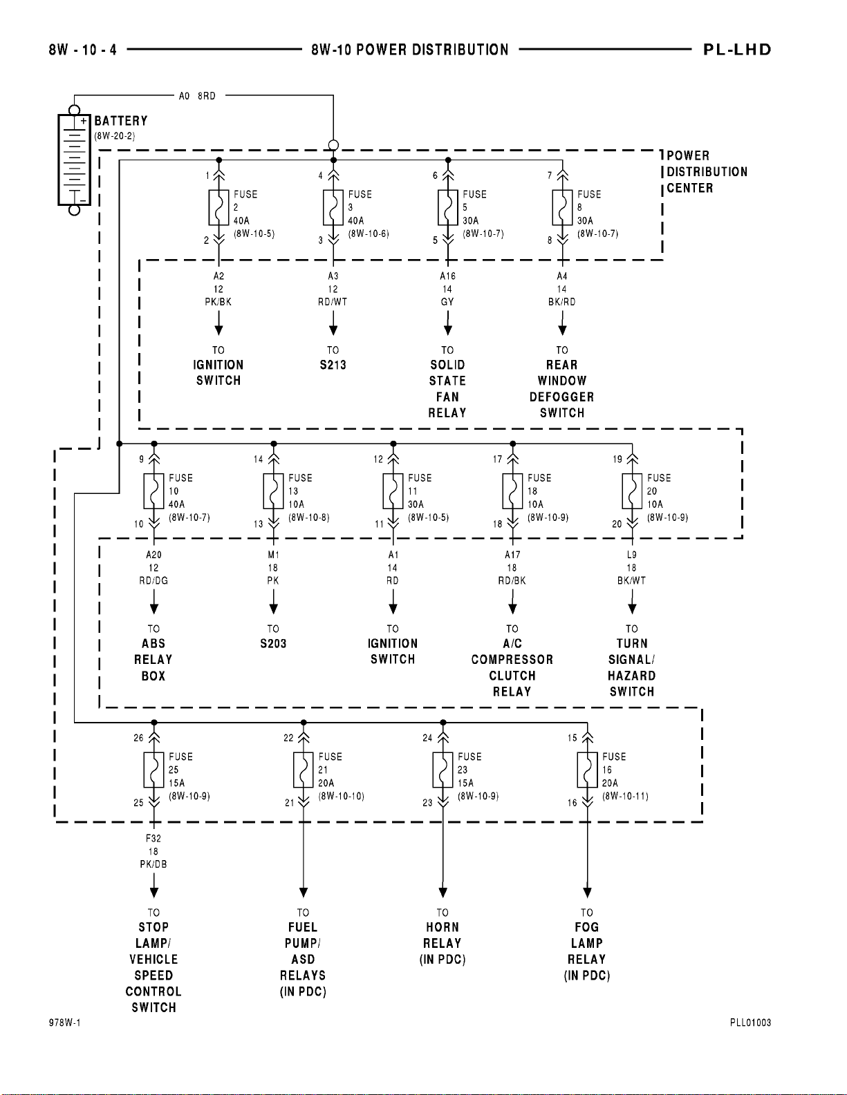
DESCRIPTION AND OPERATION ......................................................... 13
Component Page
A/C Compressor Clutch ................8W-10-9
A/C Compressor Clutch Relay ...........8W-10-9
ABS Relay Box ......................8W-10-7
Automatic Shut Down Relay ...........8W-10-10
Battery ............................8W-10-4
Capacitor ..........................8W-10-10
Circuit Breaker ......................8W-10-6
Clutch Pedal Position Switch ..........8W-10-12
Data Link Connector .................8W-10-10
Dome Lamp .........................8W-10-8
Downstream Heated Oxygen Sensor .....8W-10-10
Engine Starter Motor .................8W-10-5
Engine Starter Motor Relay .........8W-10-5, 12
Engine Starter Motor Relay ............8W-10-5
Fog Lamp Relay ....................8W-10-11
Fuel Injector No. 1 ..................8W-10-10
Fuel Injector No. 2 ..................8W-10-10
Fuel Injector No. 3 ..................8W-10-10
Fuel Injector No. 4 ..................8W-10-10
Fuel Pump Module ..................8W-10-10
Fuel Pump Relay ....................8W-10-10
Fuse 1 (FB) .........................8W-10-6
Fuse 2 (PDC) ......................8W-10-4, 5
Fuse 3 (PDC) ......................8W-10-4, 6
Fuse 4 (FB) .........................8W-10-6
Fuse 5 (FB) .........................8W-10-6
Fuse 5 (PDC) ......................8W-10-4, 7
Fuse 6 (FB) .........................8W-10-6
Fuse 7 (FB) .........................8W-10-6
Fuse 8 (FB) .........................8W-10-6
Fuse 8 (PDC) ......................8W-10-4, 7
Fuse 9 (FB) ........................8W-10-12
Fuse 10 (FB) .......................8W-10-12
Fuse 10 (PDC) .....................8W-10-4, 7
Fuse 11 (FB) .......................8W-10-12
Fuse 11 (PDC) .....................8W-10-4, 5
Fuse 13 (PDC) .....................8W-10-4, 8
Fuse 14 (FB) .......................8W-10-12
Fuse 15 (FB) .......................8W-10-12
Fuse 16 (FB) .......................8W-10-12
Fuse 16 (PDC) ....................8W-10-4, 11
Fuse 18 (PDC) .....................8W-10-4, 9
Fuse 20 (PDC) .....................8W-10-4, 9
Fuse 21 (PDC) ....................8W-10-4, 10
Fuse 23 (PDC) ....................8W-10-4, 10
Fuse 25 (PDC) .....................8W-10-4, 9
Component Page
Fuse Block .......................8W-10-6, 12
G204 ..............................8W-10-5
Generator .........................8W-10-10
Glove Box Lamp And Switch ............8W-10-8
Headlamp Switch ....................8W-10-6
Horn No. 1 .........................8W-10-9
Horn No. 2 .........................8W-10-9
Horn Relay .........................8W-10-9
Ignition Coil Pack ...................8W-10-10
Ignition Switch .................8W-10-5, 6, 12
Instrument Cluster .................8W-10-5, 8
Left Fog Lamp ......................8W-10-11
Left Visor/Vanity Lamps ...............8W-10-8
Map/Reading Lamps ..................8W-10-8
Noise Supressor .....................8W-10-10
Power Distribution Center ............8W-10-10
Power Distribution Center .......8W-10-4, 5, 6, 7,
8, 9, 10, 11
Powertrain Control Module ............8W-10-10
Power Mirror Switch ..................8W-10-8
Radiator Fan Motor ..................8W-10-7
Radio ..............................8W-10-8
Rear Fog Lamp Switch ...............8W-10-11
Rear Window Defogger Switch ..........8W-10-7
Right Fog Lamp ....................8W-10-11
Right Visor/Vanity Lamps ..............8W-10-8
S105 .............................8W-10-10
S115 .............................8W-10-11
S121 .............................8W-10-10
S122 .............................8W-10-10
S131 ..............................8W-10-9
S134 .............................8W-10-10
S202 ..............................8W-10-5
S203 ..............................8W-10-8
S208 ..............................8W-10-5
S213 ..............................8W-10-6
S217 ..............................8W-10-6
S309 ..............................8W-10-8
Solid State Fan Relay .................8W-10-7
Stop Lamp Switch ....................8W-10-9
Time Delay Relay ....................8W-10-8
Trunk Lamp ........................8W-10-8
Turn Signal/Hazard Switch .............8W-10-9
Underhood Lamp ....................8W-10-8
Upstream Heated Oxygen Sensor .......8W-10-10
Page 20
Page 21
Page 22
Page 23
Page 24
Page 25
Page 26
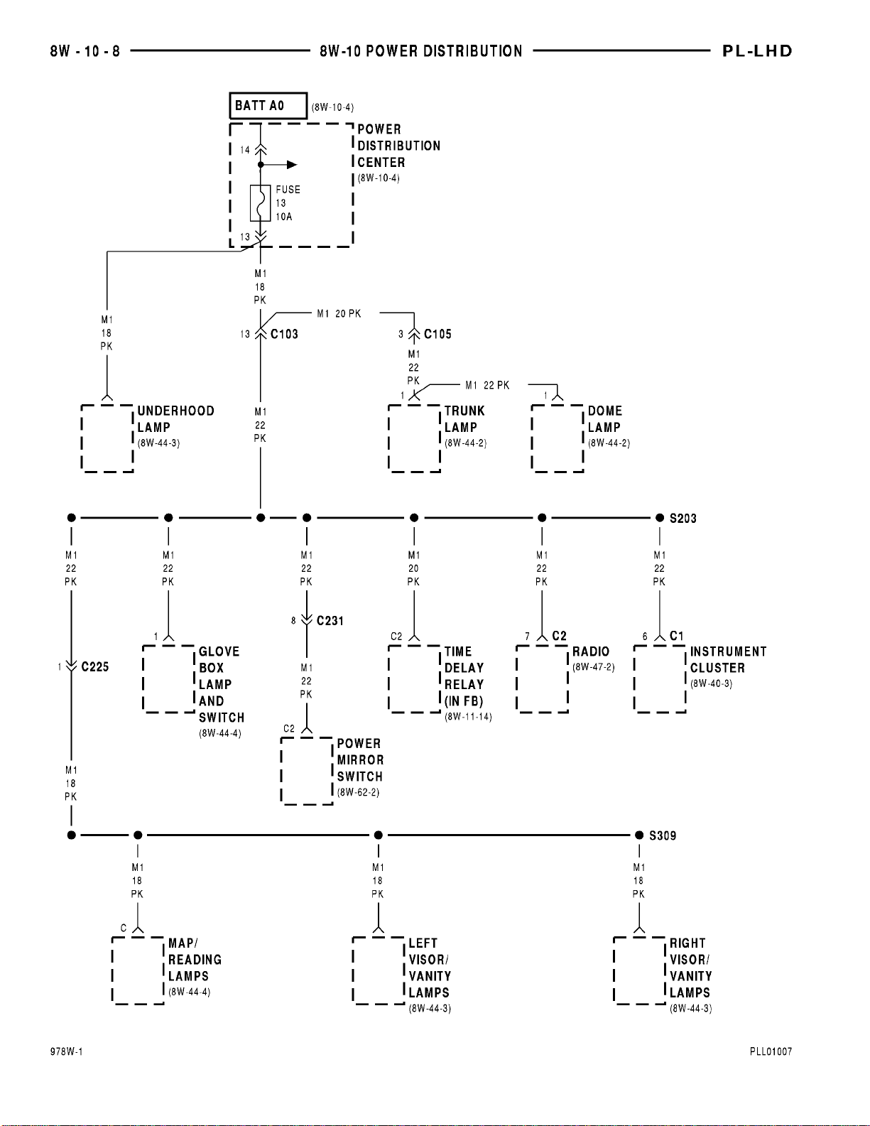
Page 27
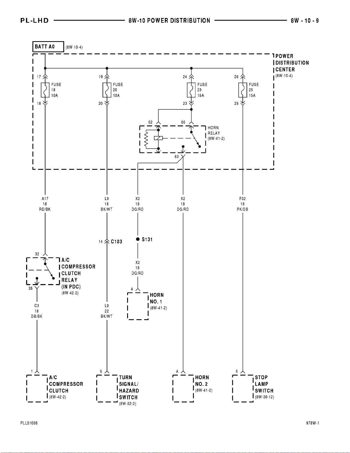
Page 28
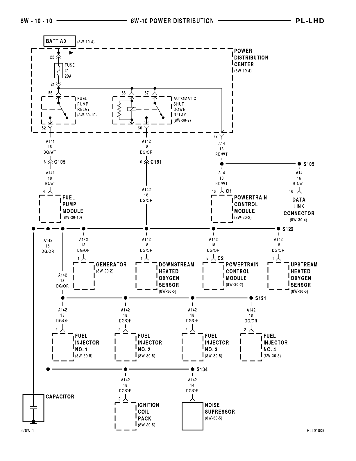
Page 29
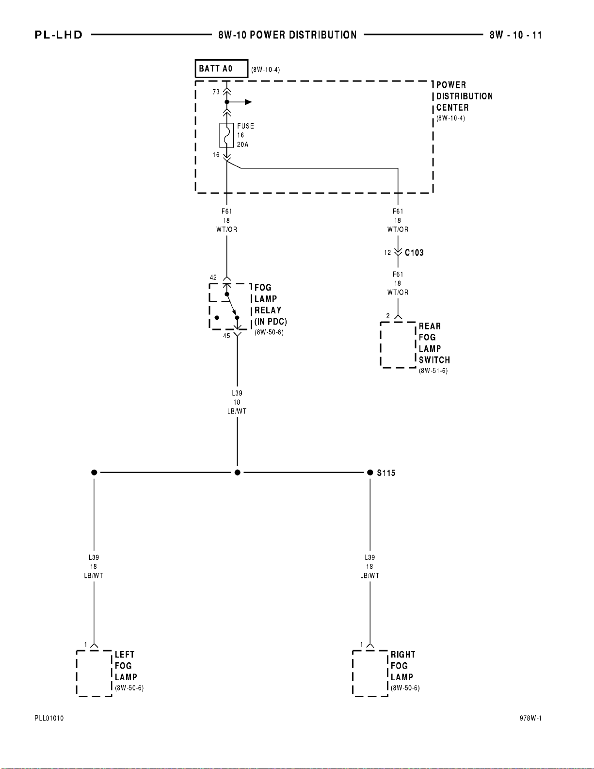
Page 30
Page 31

PL 8W - 10 POWER DISTRIBUTION 8W - 10 - 13
8W-10 POWER DISTRIBUTION
DESCRIPTION AND OPERATION
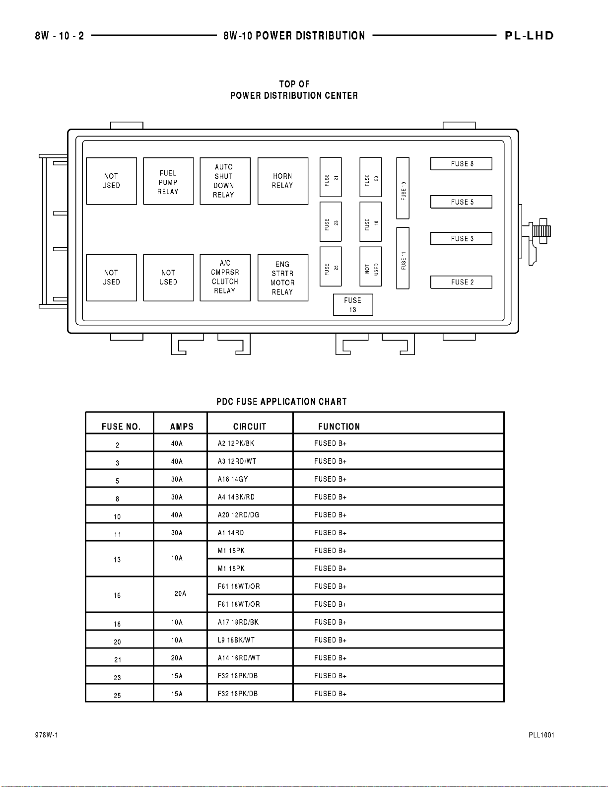
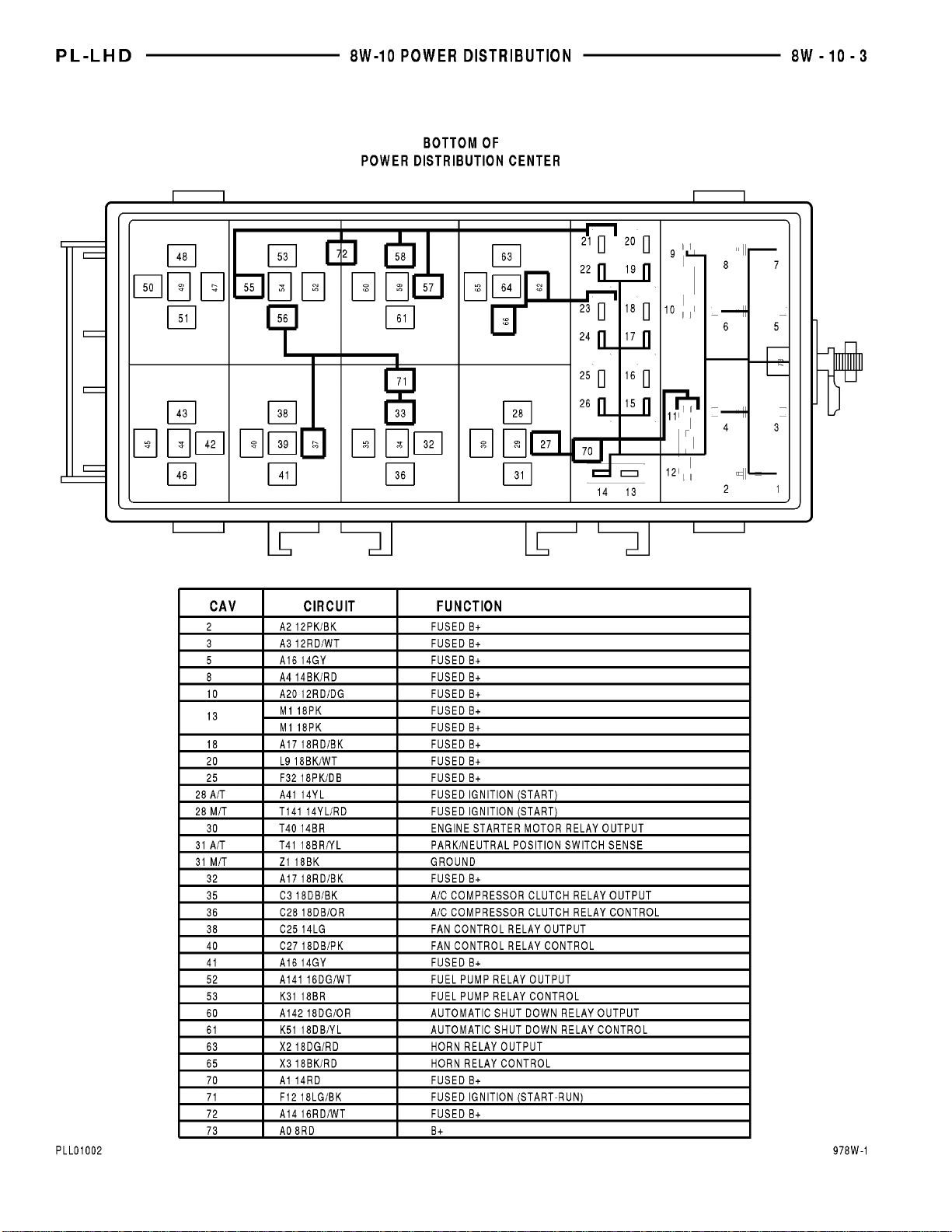
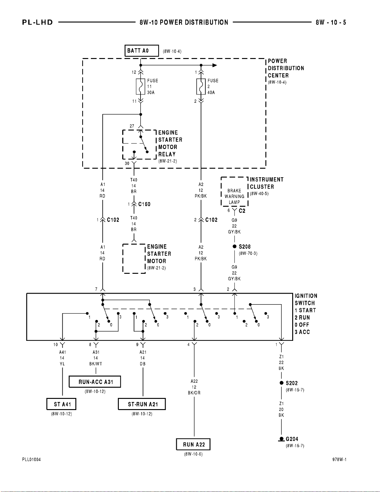
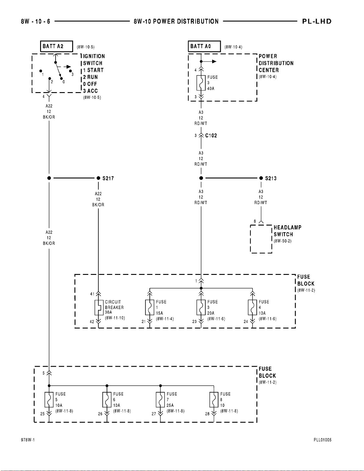
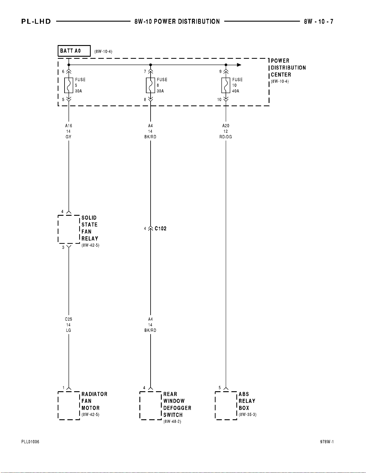
This section covers the power distribution center
and all circuits involved with it. For additional information on system operation, refer to the appropriate
wiring diagrams.
Page 32

Page 33

PL 8W - 11 FUSE/FUSE BLOCK 8W - 11 - 1
8W-11 FUSE/FUSE BLOCK
INDEX
page
SCHEMATICS AND DIAGRAMS ........................................................... 1
DESCRIPTION AND OPERATION ......................................................... 15
Component Page
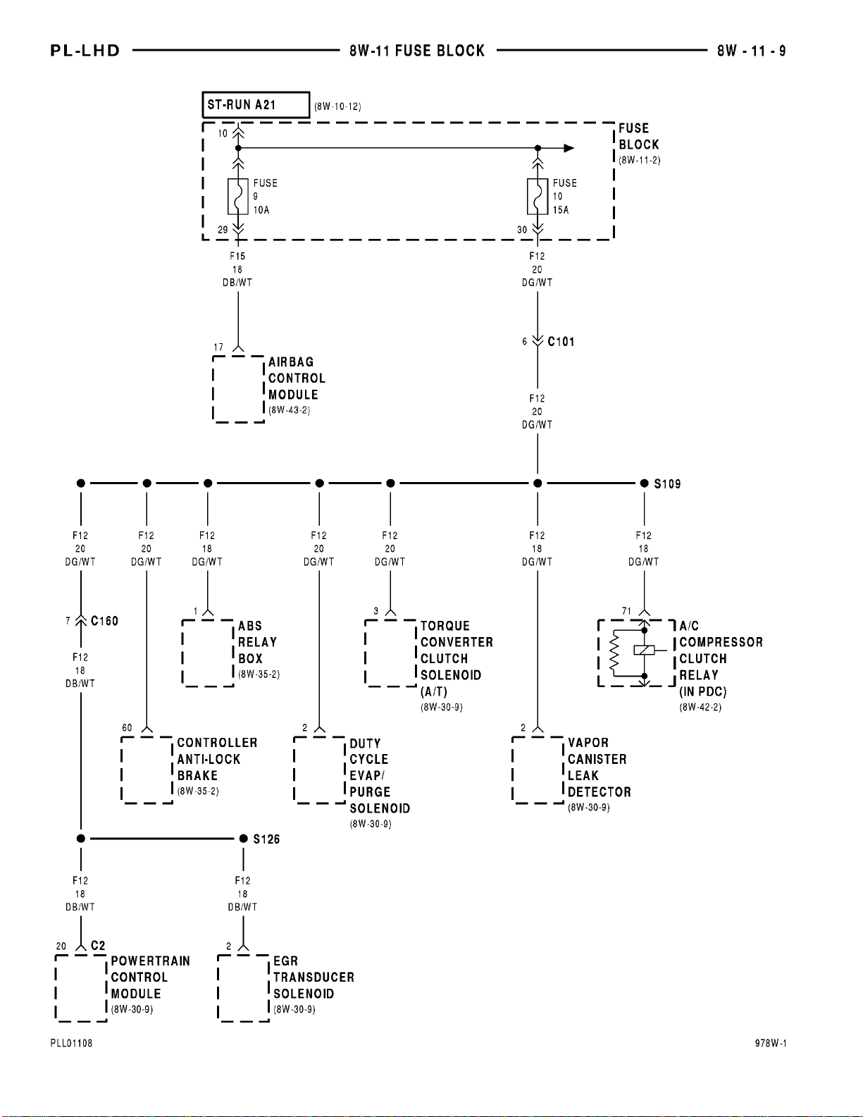
A/C Compressor Clutch Relay ...........8W-11-9
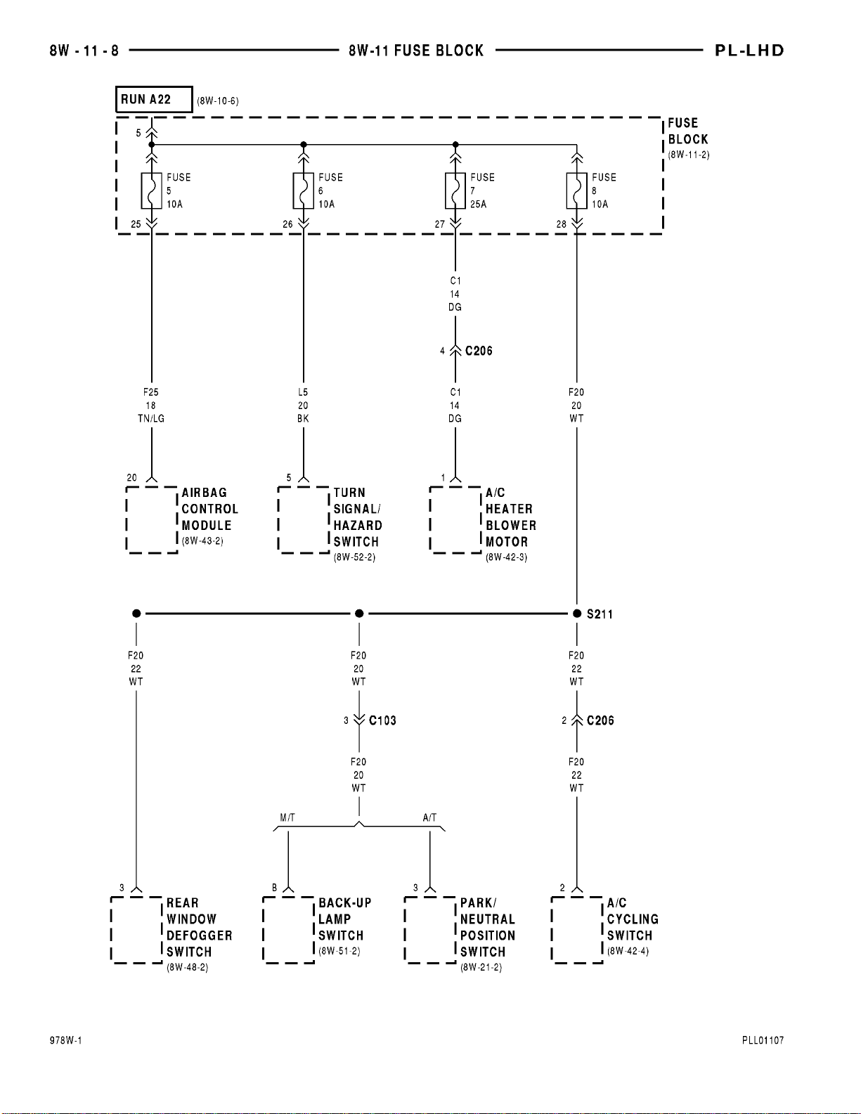
A/C Cycling Switch ...................8W-11-8
A/C Heater Blower Motor ..............8W-11-8
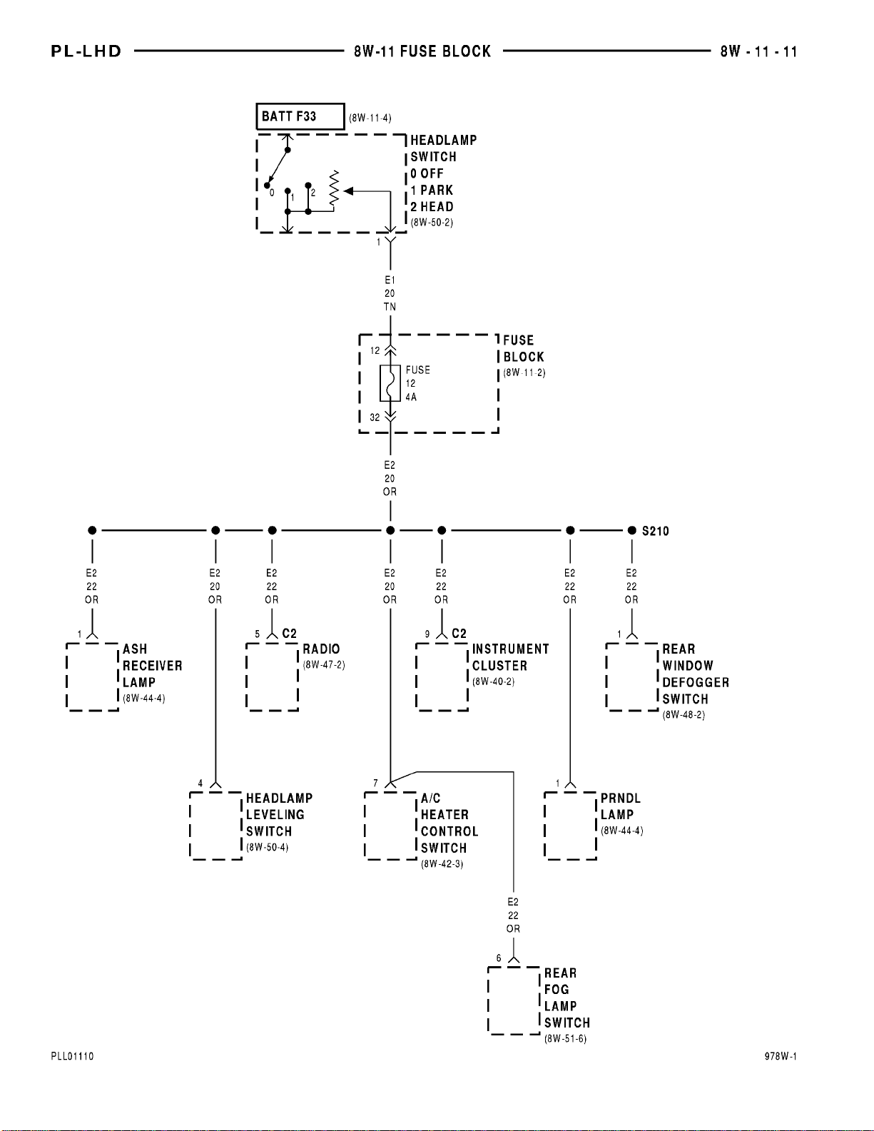
A/C Heater Control Switch ............8W-11-11
ABS Relay Box ......................8W-11-9
Airbag Control Module ..............8W-11-8, 9
Ash Receiver Lamp ..................8W-11-11
Back-Up Lamp Switch .................8W-11-8
Cigar Lighter/Power Outlet .............8W-11-4
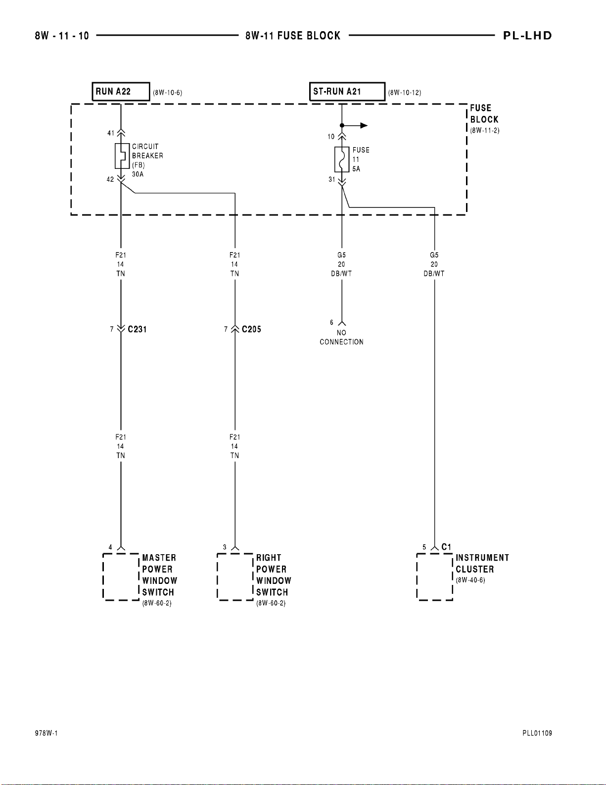
Circuit Breaker ................8W-11-7, 10, 13
Controller Anti-Lock Brake .............8W-11-9
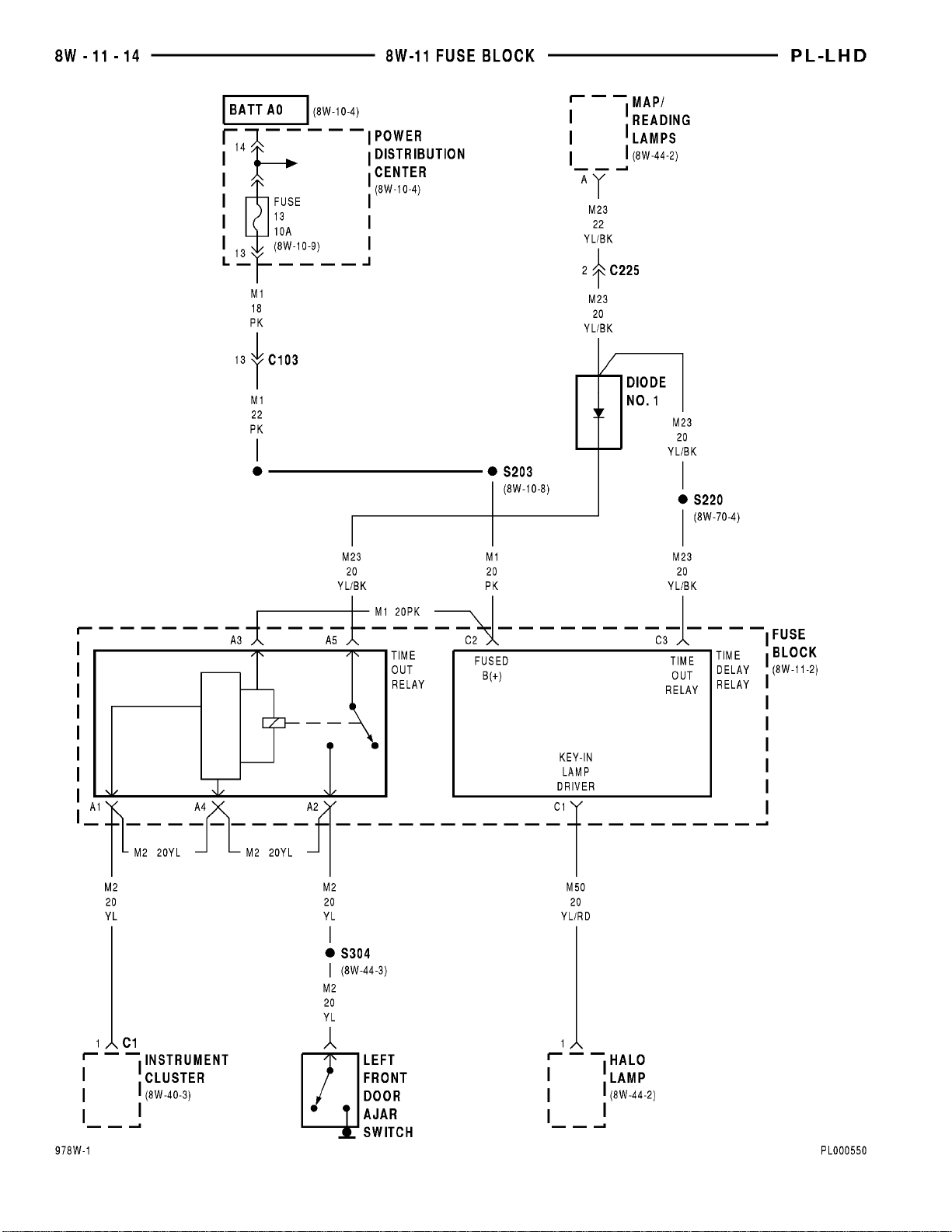
Diode No. 1 ........................8W-11-14
Duty Cycle Evap/Purge Solenoid .........8W-11-9
EGR Transducer Solenoid ..............8W-11-9
Front Fog Lamp Switch ................8W-11-4
Fuse 1 (FB) .........................8W-11-4
Fuse 2 (FB) .........................8W-11-4
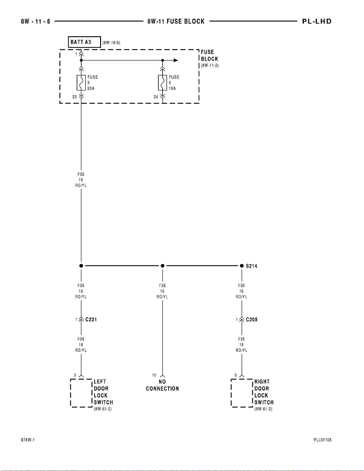
Fuse 3 (FB) .........................8W-11-6
Fuse 4 (FB) .........................8W-11-6
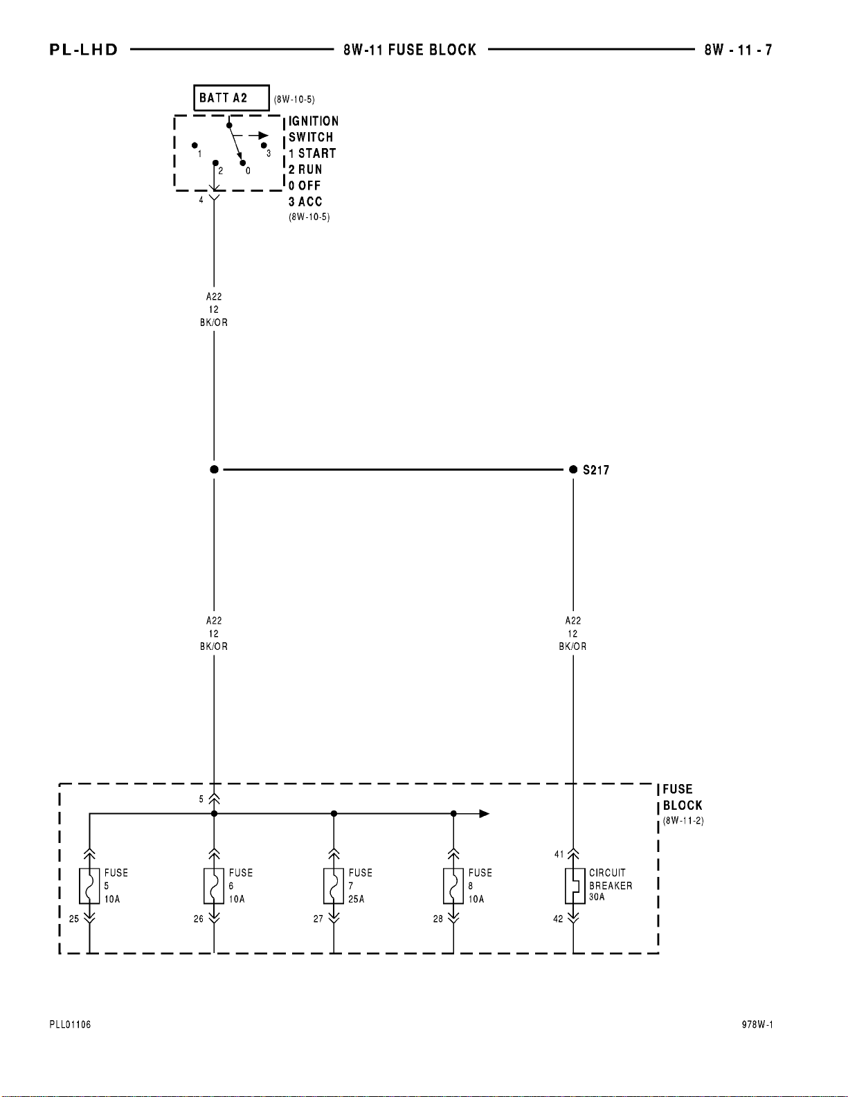
Fuse 5 (FB) .......................8W-11-7, 8
Fuse 6 (FB) .......................8W-11-7, 8
Fuse 7 (FB) .......................8W-11-7, 8
Fuse 8 (FB) .......................8W-11-7, 8
Fuse 9 (FB) .........................8W-11-9
Fuse 10 (FB) ........................8W-11-9
Fuse 11 (FB) .......................8W-11-10
Fuse 12 (FB) .....................8W-11-4, 11
Fuse 13 (PDC) ......................8W-11-14
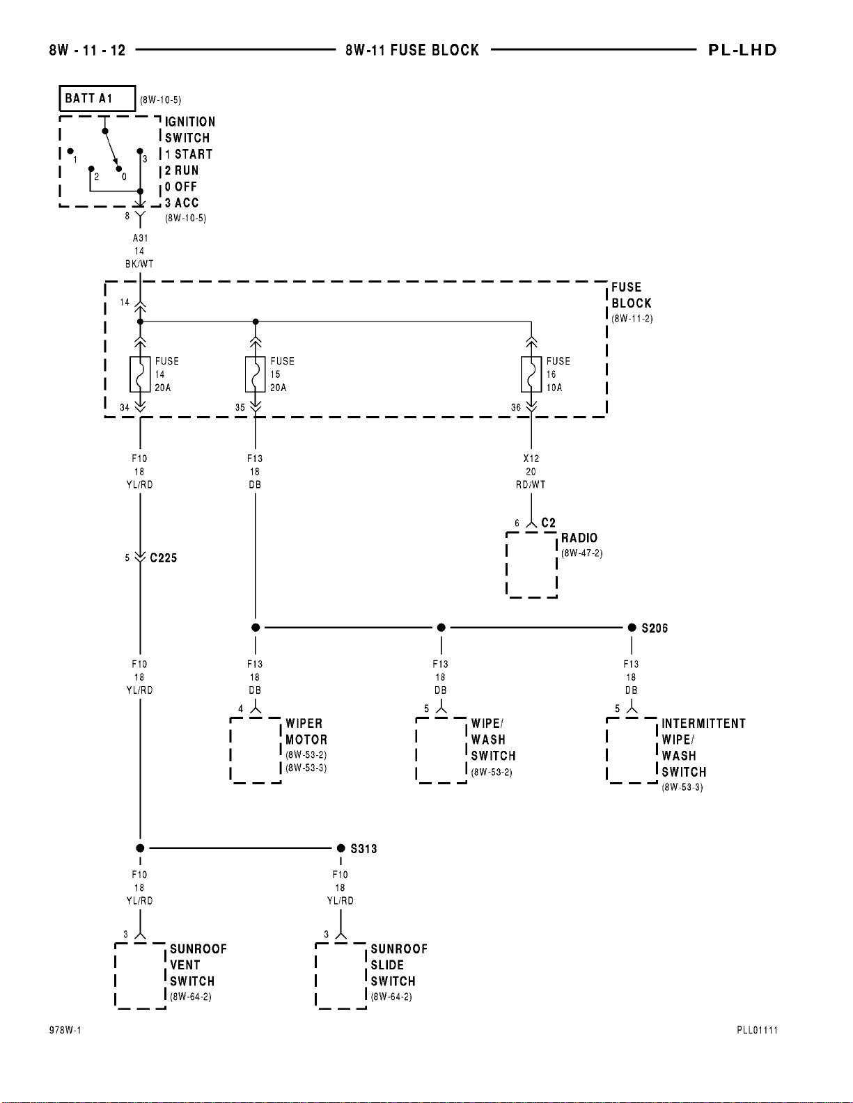
Fuse 14 (FB) .......................8W-11-12
Fuse 15 (FB) .......................8W-11-12
Fuse 16 (FB) .......................8W-11-12
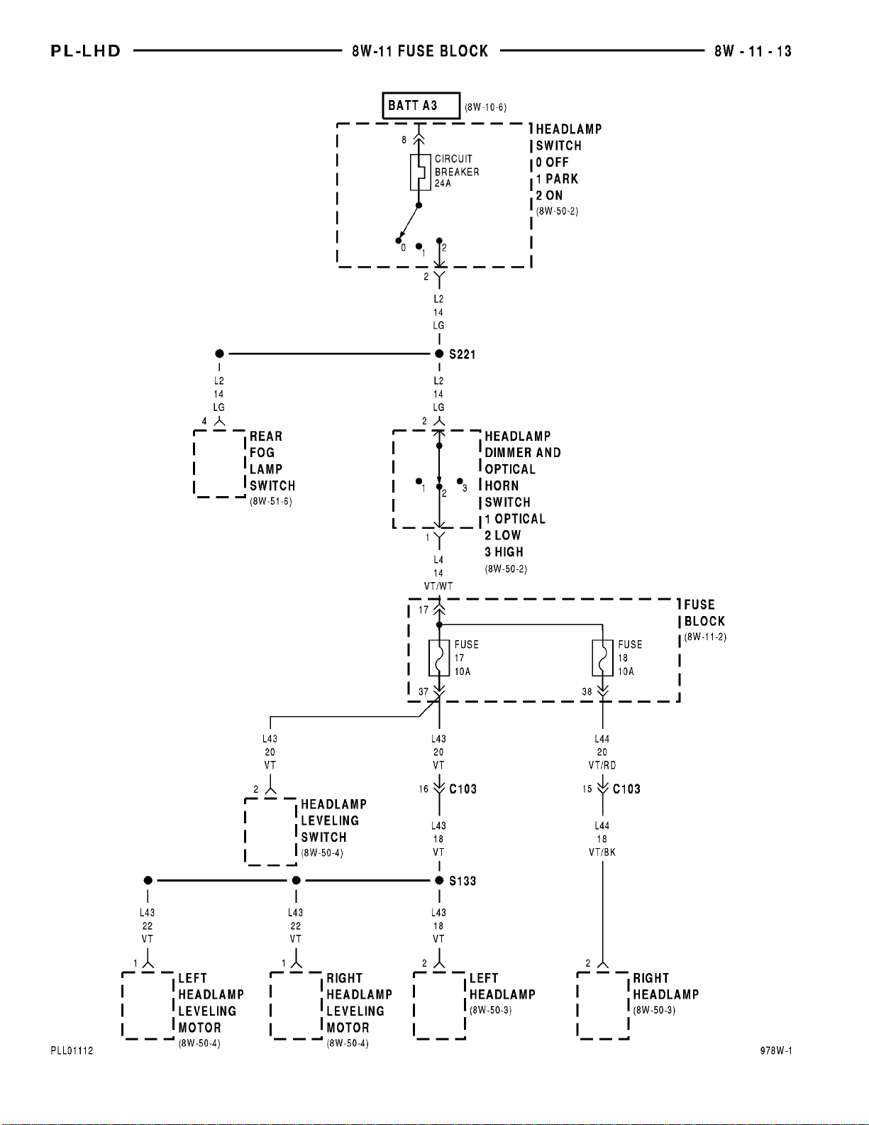
Fuse 17 (FB) .......................8W-11-13
Fuse 18 (FB) .......................8W-11-13
Fuse Block . . 8W-11-2, 4, 6, 7, 8, 9, 10, 11, 12, 13, 14
Halo Lamp .........................8W-11-14
Headlamp Dimmer And Optical
Horn Switch .....................8W-11-13
Headlamp Leveling Switch .........8W-11-11,13
Headlamp Switch ...............8W-11-4, 11, 13
Ignition Switch ...................8W-11-7, 12
Instrument Cluster ............8W-11-10, 11, 14
Intermittent Wipe/Wash Switch .........8W-11-12
Left Door Lock Switch .................8W-11-6
Left Front Door Ajar Switch ...........8W-11-14
Component Page
Left Headlamp ......................8W-11-13
Left Headlamp Leveling Motor .........8W-11-13
Left License Lamp ....................8W-11-4
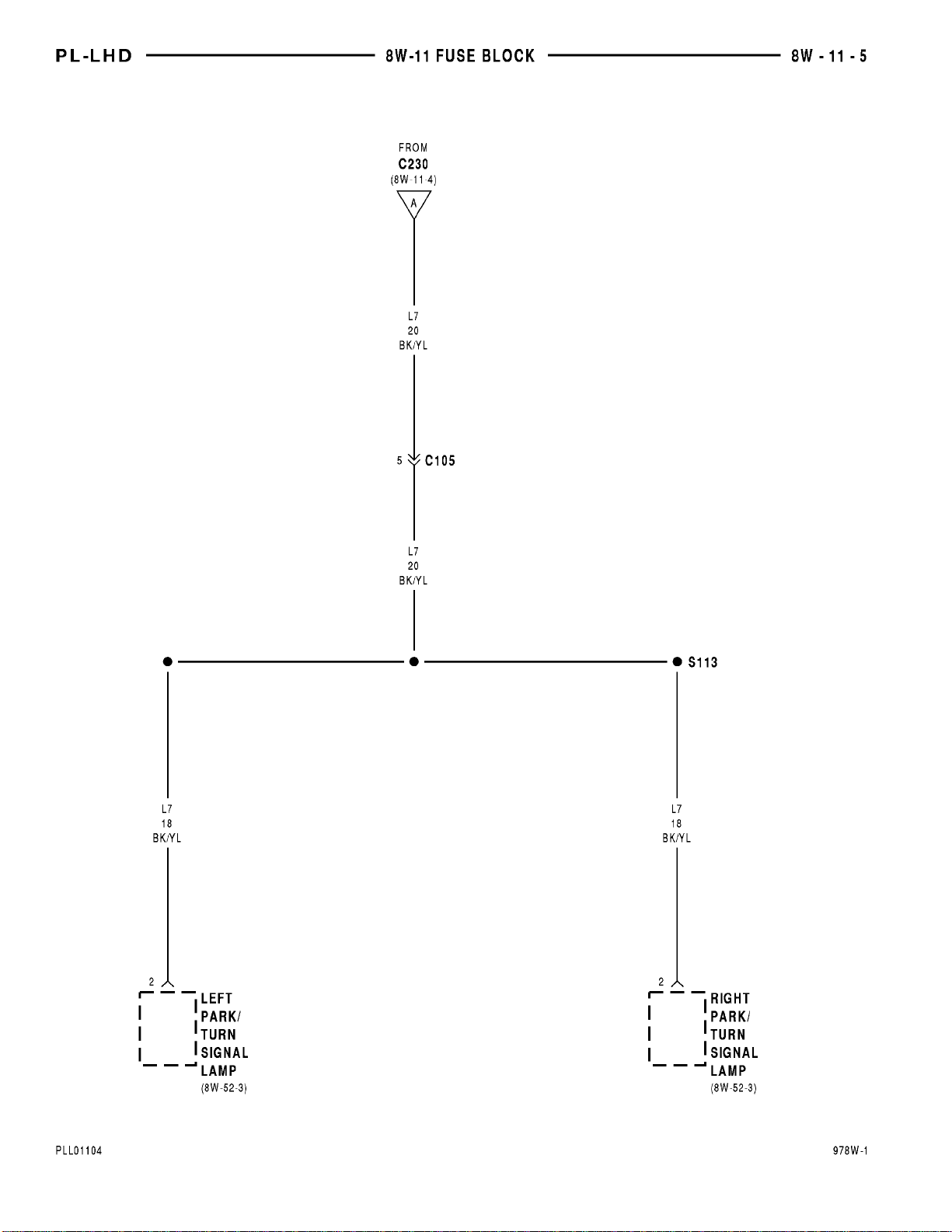
Left Park/Turn Signal Lamp ............8W-11-5
Left Tail/Stop Lamp ..................8W-11-4
Map/Reading Lamps .................8W-11-14
Master Power Window Switch ..........8W-11-10
Park/Neutral Position Switch ...........8W-11-8
Powertrain Control Module .............8W-11-9
PRNDL Lamp ......................8W-11-11
Radio ........................8W-11-4, 11, 12
Rear Fog Lamp Switch ............8W-11-11,13
Rear Window Defogger Switch ........8W-11-8, 11
Right Door Lock Switch ................8W-11-6
Right Headlamp ....................8W-11-13
Right Headlamp Leveling Motor ........8W-11-13
Right License Lamp ..................8W-11-4
Right Park/Turn Signal Lamp ...........8W-11-5
Right Power Window Switch ...........8W-11-10
Right Tail/Stop Lamp .................8W-11-4
S109 ..............................8W-11-9
S113 ..............................8W-11-5
S126 ..............................8W-11-9
S133 .............................8W-11-13
S138 .............................8W-11-10
S203 .............................8W-11-14
S206 .............................8W-11-12
S210 .............................8W-11-11
S211 ..............................8W-11-8
S214 ..............................8W-11-6
S217 ..............................8W-11-7
S220 .............................8W-11-14
S221 .............................8W-11-13
S304 .............................8W-11-14
S306 ..............................8W-11-4
S313 .............................8W-11-12
Sunroof Slide Switch .................8W-11-12
Sunroof Vent Switch .................8W-11-12
Torque Converter Clutch Solenoid ........8W-11-9
Turn Signal/Hazard Switch .............8W-11-8
Vapor Canister Leak Detector ...........8W-11-9
Wipe/Wash Switch ...................8W-11-12
Wiper Motor .......................8W-11-12
Page 34
Page 35
Page 36
Page 37
Page 38
Page 39
Page 40
Page 41
Page 42
Page 43
Page 44
Page 45
Page 46
Page 47

PL 8W - 11 FUSE/FUSE BLOCK 8W - 11 - 15
8W-11 FUSE/FUSE BLOCK
DESCRIPTION AND OPERATION
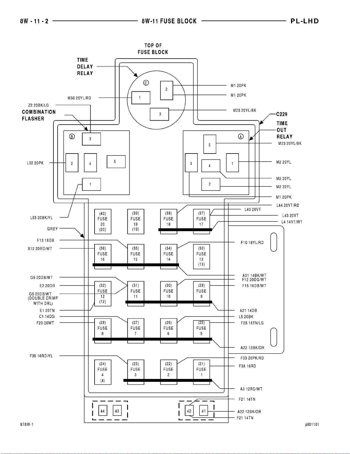
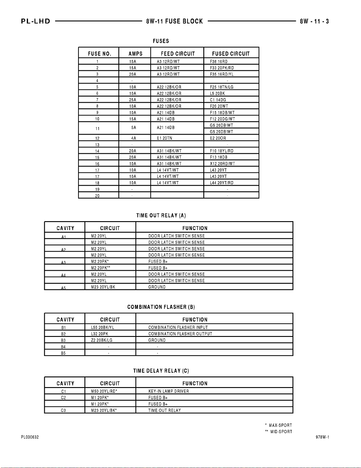
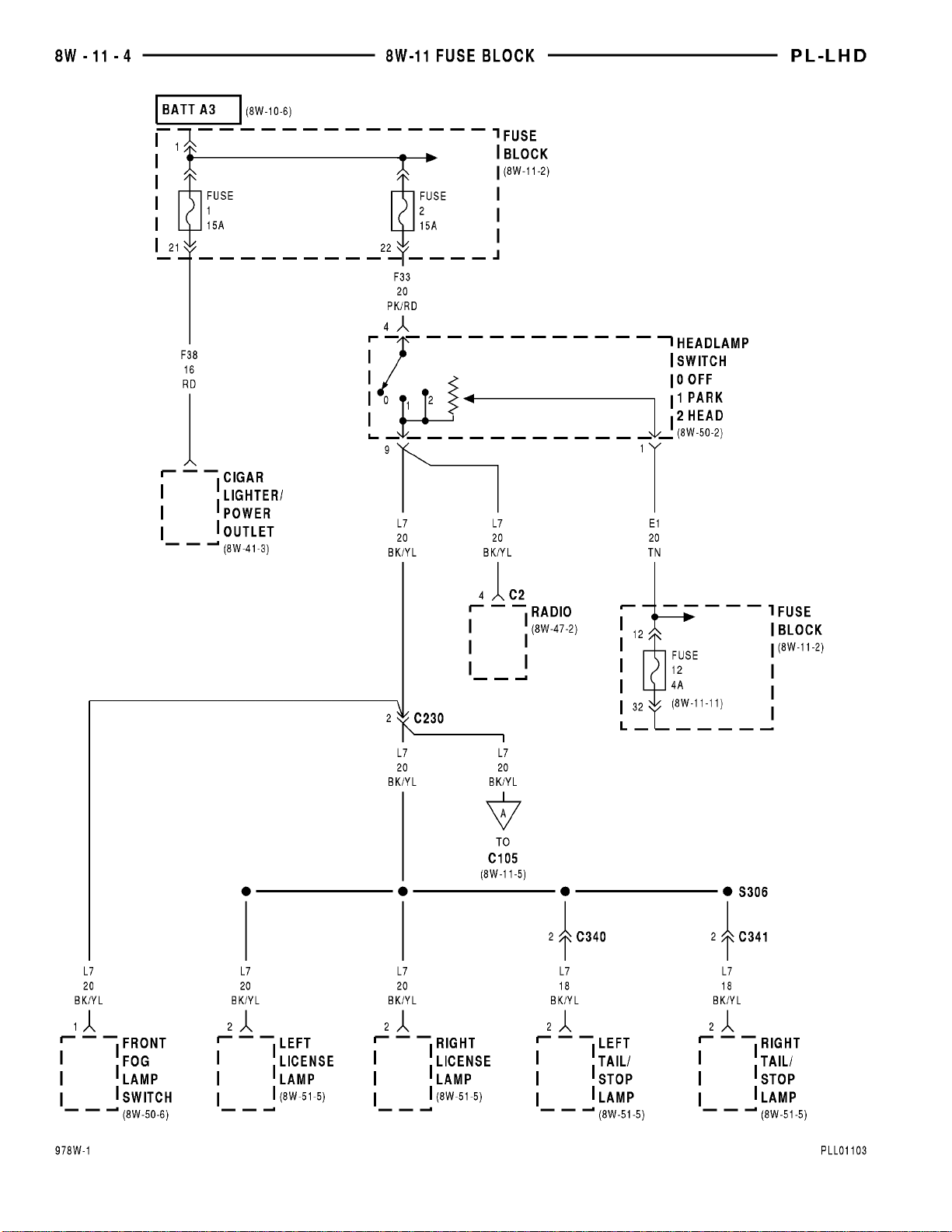
This section covers the fuse block and all circuits
involved with it. For additional information on system operation, please refer to the appropriate section
of the wiring diagrams.
Page 48

Page 49

PL 8W - 15 GROUND DISTRIBUTION 8W - 15 - 1
8W-15 GROUND DISTRIBUTION
INDEX
page
SCHEMATICS AND DIAGRAMS ........................................................... 1
GENERAL INFORMATION ............................................................... 10
Component Page
A/C Compressor Clutch ................8W-15-4
A/C Compressor Clutch Relay ...........8W-15-4
A/C Heater Control Switch .............8W-15-6
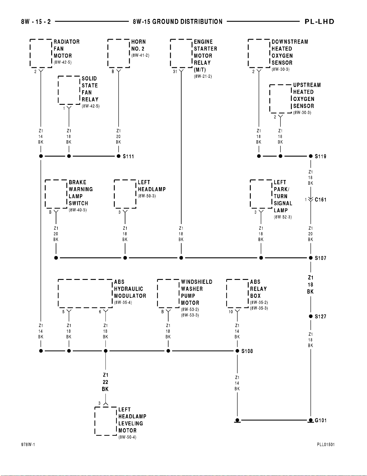
ABS Hydraulic Modulator ..............8W-15-2
ABS Relay Box ......................8W-15-2
Airbag Control Module ................8W-15-5
Ash Receiver Lamp ...................8W-15-7
Battery ............................8W-15-5
Brake Warning Lamp Switch ...........8W-15-2
Cigar Lighter/Power Outlet .............8W-15-7
Combination Flasher ..................8W-15-5
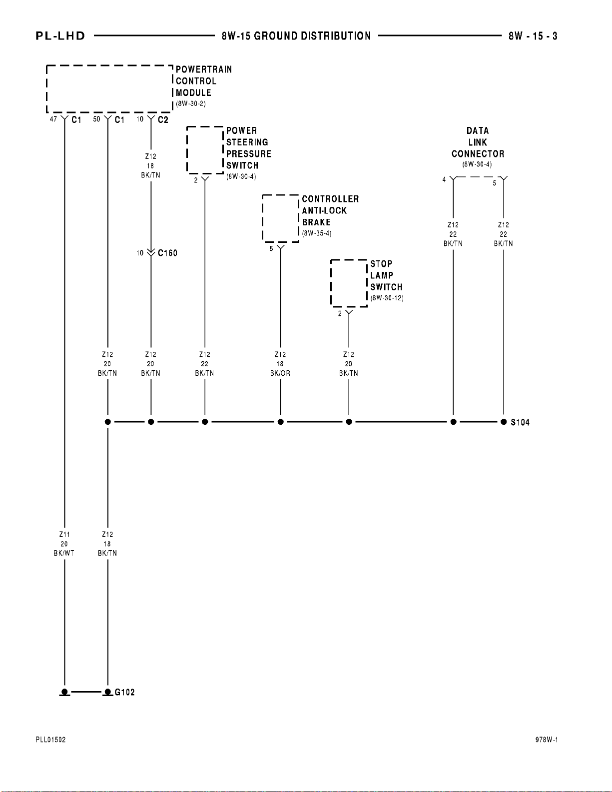
Controller Anti-Lock Brake .............8W-15-3
Data Link Connector ..................8W-15-3
Diode No. 2 .........................8W-15-4
Downstream Heated Oxygen Sensor ......8W-15-2
Engine Starter Motor Relay ............8W-15-2
Front Fog Lamp Switch ...............8W-15-7
Fuel Pump Module ...................8W-15-9
G101 ..............................8W-15-2
G102 ..............................8W-15-3
G103 ..............................8W-15-4
G104 ..............................8W-15-5
G105 ..............................8W-15-5
G106 ..............................8W-15-5
G201 ..............................8W-15-5
G202 ..............................8W-15-5
G203 ..............................8W-15-6
G204 ..............................8W-15-7
G301 ..............................8W-15-9
G302 ..............................8W-15-8
G303 ..............................8W-15-9
Glove Box Lamp And Switch ............8W-15-7
Headlamp Leveling Switch .............8W-15-7
Headlamp Switch ....................8W-15-7
Horn No. 1 .........................8W-15-4
Horn No. 2 .........................8W-15-2
Ignition Switch ......................8W-15-7
Instrument Cluster ...................8W-15-7
Intermittent Wipe/Wash Switch .........8W-15-5
Left Back-Up Lamp ...................8W-15-8
Left Door Lock Switch .................8W-15-7
Left Fog Lamp ......................8W-15-4
Left Headlamp ......................8W-15-2
Left Headlamp Leveling Motor ..........8W-15-2
Left License Lamp ...................8W-15-8
Left Park/Turn Signal Lamp ............8W-15-2
Component Page
Left Rear Fog Lamp ..................8W-15-8
Left Tail/Stop Lamp ..................8W-15-8
Left Turn Signal Lamp ................8W-15-8
Map/Reading Lamps ..................8W-15-7
Master Power Window Switch ...........8W-15-6
Power Mirror Switch ..................8W-15-6
Power Steering Pressure Switch .........8W-15-3
Power Sunroof Motor .................8W-15-6
Powertrain Control Module ...........8W-15-3, 5
PRNDL Lamp .......................8W-15-7
Radiator Fan Motor ..................8W-15-2
Radio ..............................8W-15-5
Rear Fog Lamp Switch ................8W-15-7
Rear Window Defogger ................8W-15-9
Rear Window Defogger Switch ..........8W-15-5
Right Back-Up Lamp .................8W-15-9
Right Fog Lamp .....................8W-15-4
Right Headlamp .....................8W-15-4
Right Headlamp Leveling Motor .........8W-15-4
Right License Lamp ..................8W-15-8
Right Park/Turn Signal Lamp ...........8W-15-4
Right Rear Fog Lamp .................8W-15-9
Right Repeater Lamp .................8W-15-4
Right Tail/Stop Lamp .................8W-15-9
Right Turn Signal Lamp ...............8W-15-9
S104 ..............................8W-15-3
S107 ..............................8W-15-2
S108 ..............................8W-15-2
S111 ..............................8W-15-2
S117 ..............................8W-15-4
S119 ..............................8W-15-2
S127 ..............................8W-15-2
S201 ..............................8W-15-7
S202 ..............................8W-15-7
S205 ..............................8W-15-5
S307 ..............................8W-15-9
S308 ..............................8W-15-8
S310 ..............................8W-15-6
S314 ..............................8W-15-6
S315 ..............................8W-15-8
Solid State Fan Relay .................8W-15-2
Stop Lamp Switch ....................8W-15-3
Sunroof Vent Switch ..................8W-15-6
Upstream Heated Oxygen Sensor ........8W-15-2
Windshield Washer Pump Motor .........8W-15-2
Page 50
Page 51
Page 52
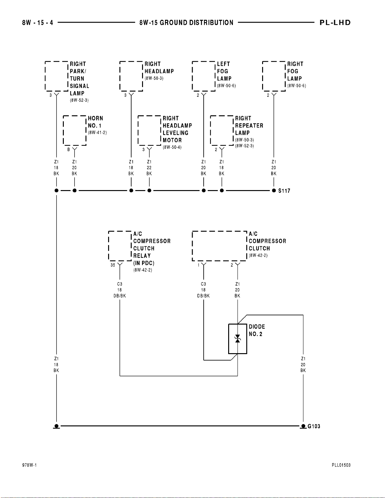
Page 53
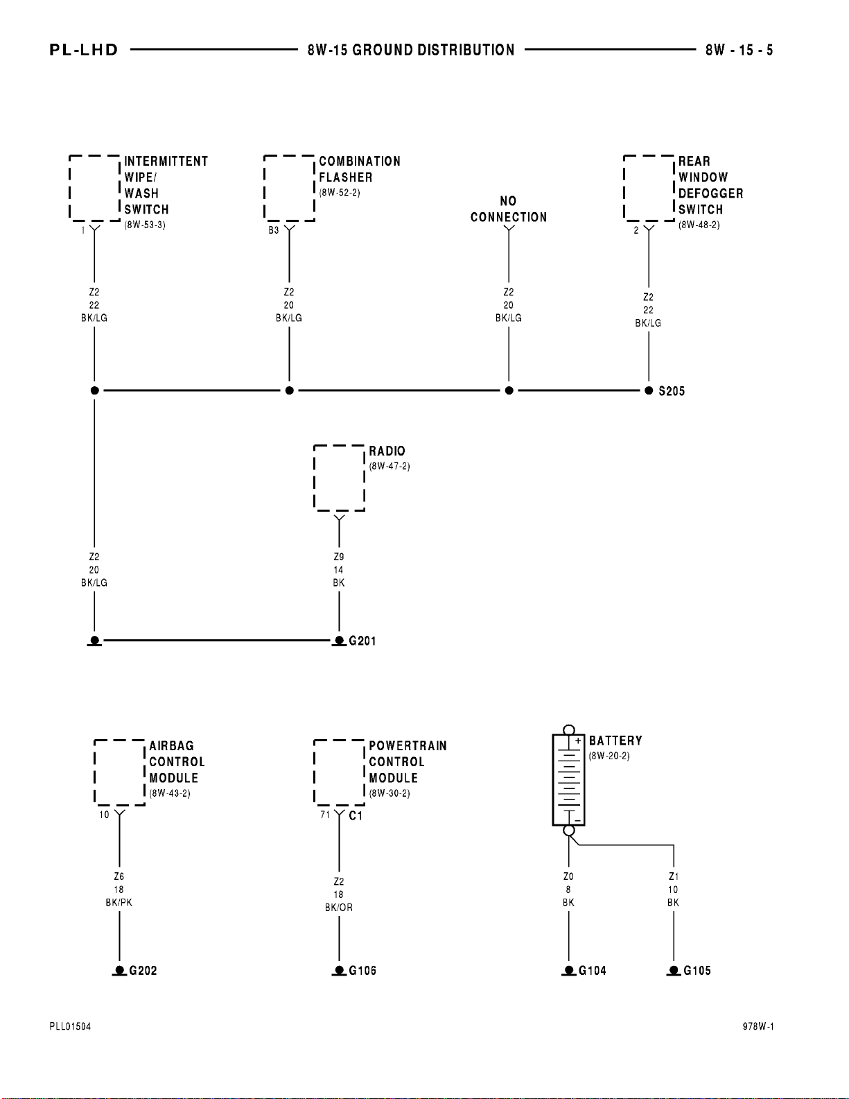
Page 54
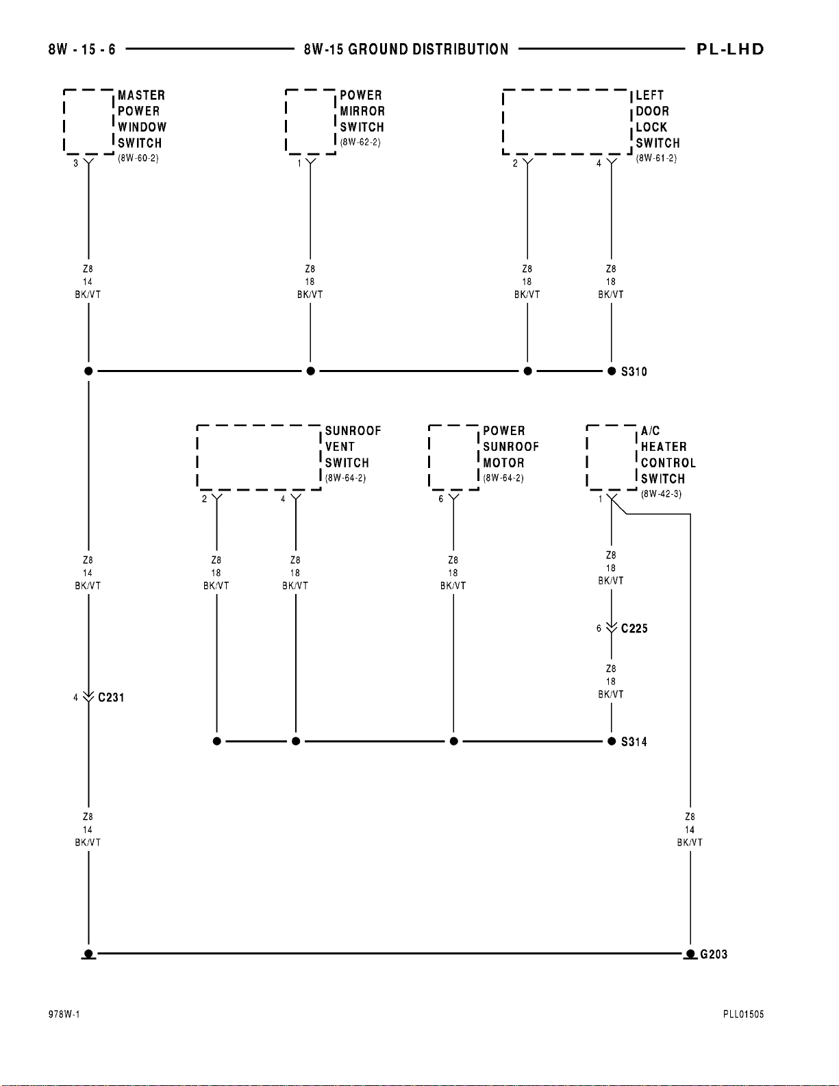
Page 55
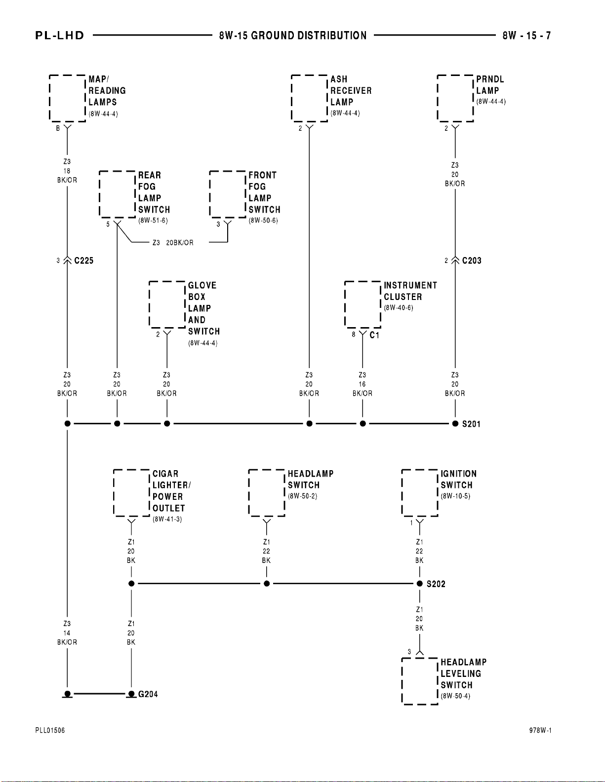
Page 56
Page 57
Page 58

8W - 15 - 10 8W - 15 GROUND DISTRIBUTION PL
8W-15 GROUND DISTRIBUTION
GENERAL INFORMATION
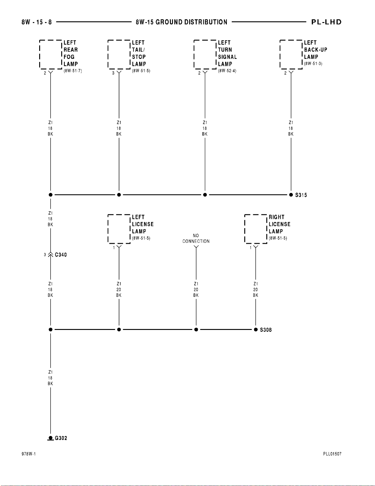
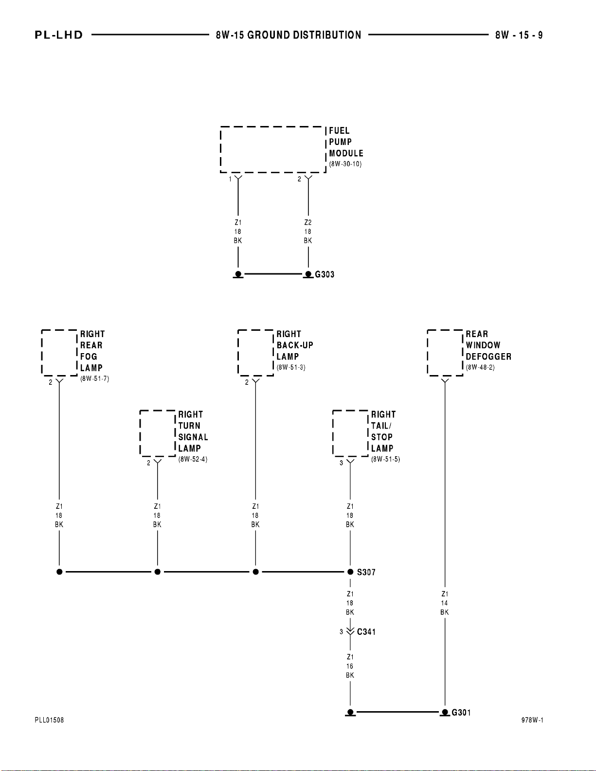
This section identifies the grounds, splices that
connect to those grounds, and the components that
connect those grounds. For additional information on
system operation, refer to the appropriate section of
the wiring diagrams. For an illustration of the physical location of each ground, refer to group 8W-90.
Page 59

PL 8W - 20 CHARGING SYSTEM 8W - 20 - 1
8W-20 CHARGING SYSTEM
INDEX
page
SCHEMATICS AND DIAGRAMS ........................................................... 1
DESCRIPTION AND OPERATION .......................................................... 3
Component Page
Automatic Shut Down Relay ............8W-20-2
Battery ............................8W-20-2
Capacitor ...........................8W-20-2
Engine Starter Motor .................8W-20-2
Fuse 21 (PDC) .......................8W-20-2
Fusible Link ........................8W-20-2
G104 ..............................8W-20-2
Component Page
G105 ..............................8W-20-2
Generator ..........................8W-20-2
Power Distribution Center .............8W-20-2
Powertrain Control Module .............8W-20-2
S122 ..............................8W-20-2
S125 ..............................8W-20-2
Page 60
Page 61

PL 8W - 20 CHARGING SYSTEM 8W - 20 - 3
8W-20 CHARGING SYSTEM
DESCRIPTION AND OPERATION
CHARGING SYSTEM
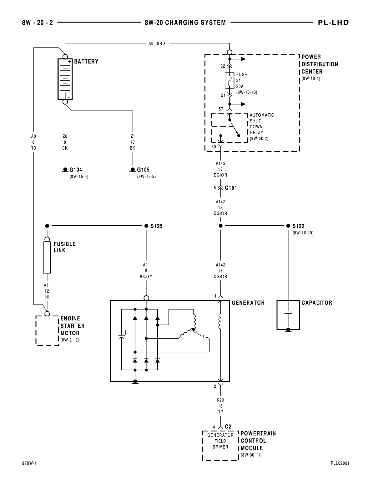
The charging system is an integral part of the battery and starter systems. Since all of these systems
work together, any diagnosis and testing should be
done in conjunction.
The charging system is protected by a 12 gauge
fusible link located in the A11 circuit. This fusible
link is between the generator and the starter.
The generator ground is provided through a case
ground in the generator to its attaching bracket. This
generator uses a voltage regulator internal to the
Powertrain Control Module (PCM).
When the vehicle is running, battery voltage is
applied to the generator field terminal through the
A142 circuit. This circuit is the output from the contact side of the Automatic Shut Down (ASD) relay.
The ground, or voltage regulated side, of the generator field is controlled by the K20 circuit which connects to cavity 4 of the PCM connector.
When there is current present in the field, and the
rotor is turning, the stator in the generator produces
a B+ voltage that is supplied to the battery through
the A11 and A0 circuits. The A11 circuit is connected
to the output terminal of the generator and connects
to the engine starter motor battery feed terminal.
The A0 circuit is a direct feed line from the battery
and connects to the engine starter motor.
Grounding for the system is accomplished at the
battery negative terminal. These grounds connect to
the engine and body.
HELPFUL INFORMATION
• Inspect for a blown fusible link in the A11 cir-
cuit between the generator and the starter motor.
• For additional information on charging system
diagnosis, refer to the appropriate section of the service manual.
Page 62

Page 63

PL 8W - 21 STARTING SYSTEM 8W - 21 - 1
8W-21 STARTING SYSTEM
INDEX
page
SCHEMATICS AND DIAGRAMS ........................................................... 1
DESCRIPTION AND OPERATION .......................................................... 3
Component Page
Battery ............................8W-21-2
Clutch Pedal Position Switch ...........8W-21-2
Engine Starter Motor .................8W-21-2
Engine Starter Motor Relay ............8W-21-2
Fuse 11 (PDC) .......................8W-21-2
Fusible Link ........................8W-21-2
G101 ..............................8W-21-2
Generator ..........................8W-21-2
Component Page
Ignition Switch ......................8W-21-2
Park/Neutral Position Switch ...........8W-21-2
Power Distribution Center .............8W-21-2
Powertrain Control Module .............8W-21-2
S106 ..............................8W-21-2
S107 ..............................8W-21-2
S125 ..............................8W-21-2
S127 ..............................8W-21-2
Page 64
Page 65

PL 8W - 21 STARTING SYSTEM 8W - 21 - 3
8W-21 STARTING SYSTEM
DESCRIPTION AND OPERATION
STARTING SYSTEM- MANUAL TRANSMISSION
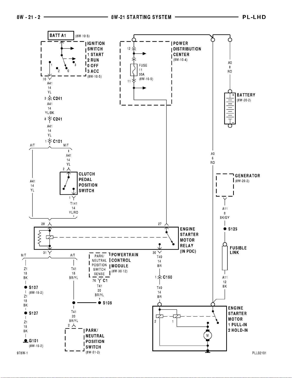
The Power Distribution Center (PDC) supplies battery voltage to the engine starter motor solenoid
through circuit T40 when the coil side of the engine
starter motor relay energizes. Circut A1 supplies the
battery voltage for the contact side of the relay. Circuit A1 and circuit T40 are protected by a 30 amp
fuse and feeds the contact side of the engine starter
motor relay. Both the 30 amp fuse and the engine
starter motor relay are located in the PDC.
The ignition switch supplies battery voltage to the
coil side of the engine starter motor relay on circuit
A41 when the key is moved to the START position
and the operator has pressed the clutch pedal to
CLOSE the clutch pedal position switch. Circuit Z1
supplies the ground for the coil side of the engine
starter motor relay. When the coil side of the relay
energizes, the contacts CLOSE, supplying battery
voltage to the engine starter motor solenoid.
Circuit A0 (battery positive cable) supplies battery
voltage to the motor of the starter when the solenoid
energizes.
HELPFUL INFORMATION
• Check for blown engine starter motor fuse in the
PDC.
• Move ignition key to the START position and
with the clutch pedal pressed, listen for starter motor
relay to click. The engine starter motor relay is
located in the PDC.
• Check for a good ground at starter motor.
• The left headlamp ground is the end point for
the starter relay coil ground circuit and is located at
the left side of the radiator closure panel.
STARTING SYSTEM (AUTOMATIC TRANSMISSION)
The Power Distribution Center (PDC) supplies battery voltage to the engine starter motor solenoid
through circuit T40 when the coil side of the engine
starter motor relay energizes. Circuit A1 supplies
battery voltage to the contact side of the relay. Circuit A1 and circuit T40 are protected by a 30 amp
fuse and feeds the contact side of the engine starter
motor relay. Both the 30 amp fuse and the engine
starter motor relay are located in the PDC.
The ignition switch supplies battery voltage to the
coil side of the engine starter motor relay on circuit
A41 when the key is moved to the START position
and the park/neutral portion of the park/neutral position switch (3 speed transmission) is CLOSED.
Ground for the coil side of the engine starter motor
relay is supplied by circuit T41.
Circuit A0 (battery positive cable) supplies battery
voltage to the motor of the engine starter when the
solenoid energizes.
HELPFUL INFORMATION
• Check for blown engine starter motor fuse in the
PDC.
• With the gear selector in the Park or Neutral
position, move ignition key to the START position
and listen for engine starter motor relay to click. The
engine starter motor relay is located in the PDC.
• Check for a good ground at engine starter motor.
Page 66

Page 67

PL 8W - 30 FUEL/IGNITION SYSTEMS 8W - 30 - 1
8W-30 FUEL/IGNITION SYSTEMS
INDEX
page
SCHEMATICS AND DIAGRAMS ........................................................... 1
DESCRIPTION AND OPERATION ......................................................... 14
Component Page
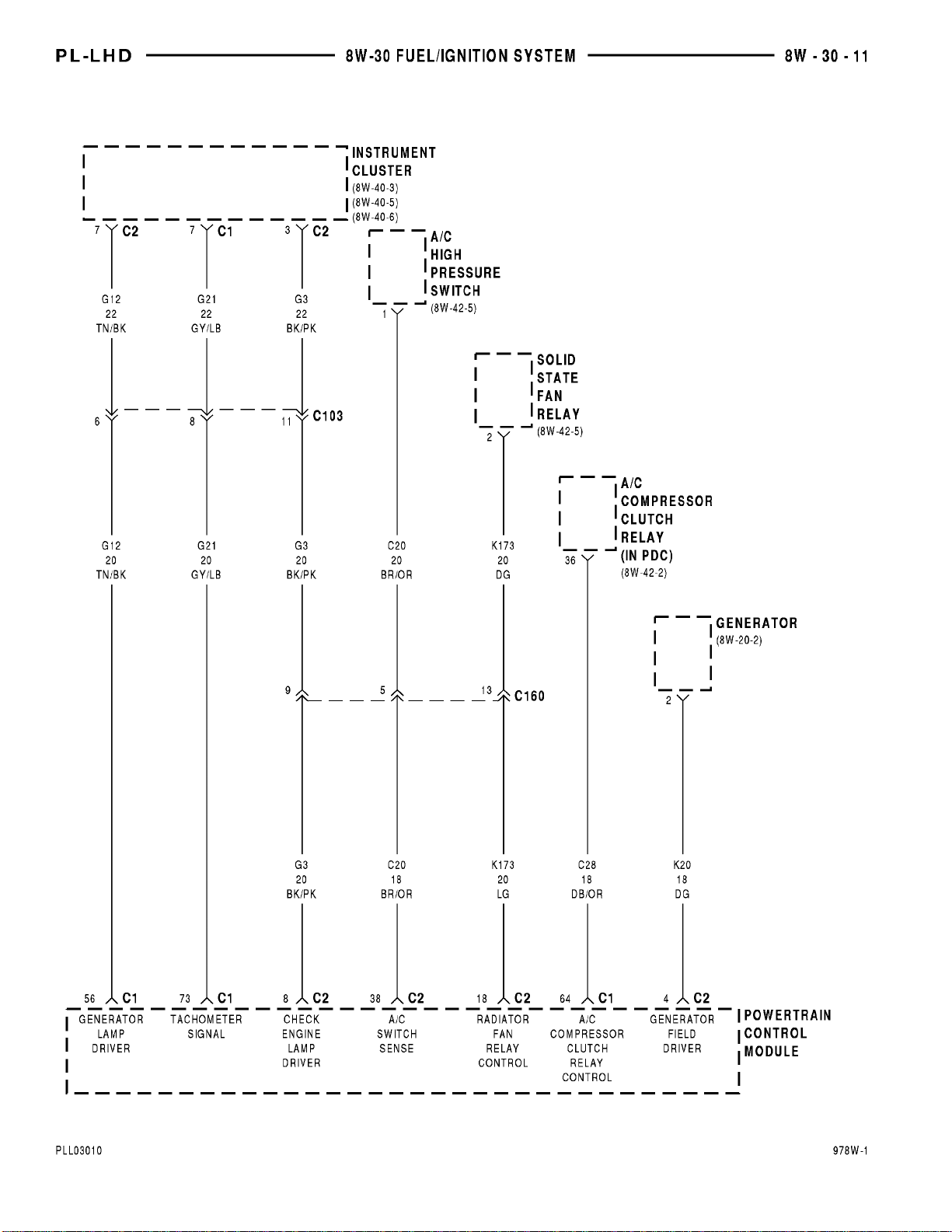
A/C Compressor Clutch Relay ..........8W-30-11
A/C High Pressure Switch .............8W-30-11
Airbag Control Module ................8W-30-4
Automatic Shut Down Relay ..........8W-30-2, 3
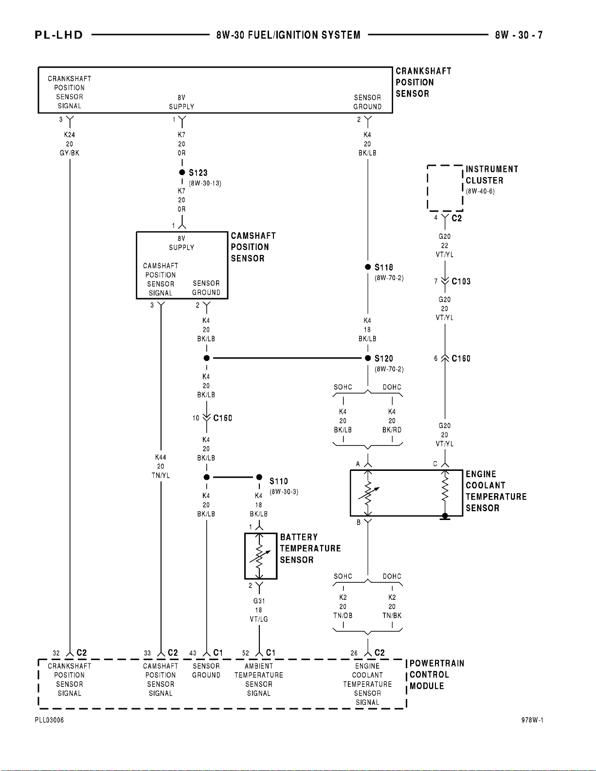
Battery Temperature Sensor ..........8W-30-3, 7
Camshaft Position Sensor ...........8W-30-7, 13
Controller Anti-Lock Brake ..........8W-30-4, 12
Crankshaft Position Sensor ..........8W-30-7, 13
Data Link Connector ................8W-30-2, 4
Downstream Heated Oxygen Sensor ......8W-30-3
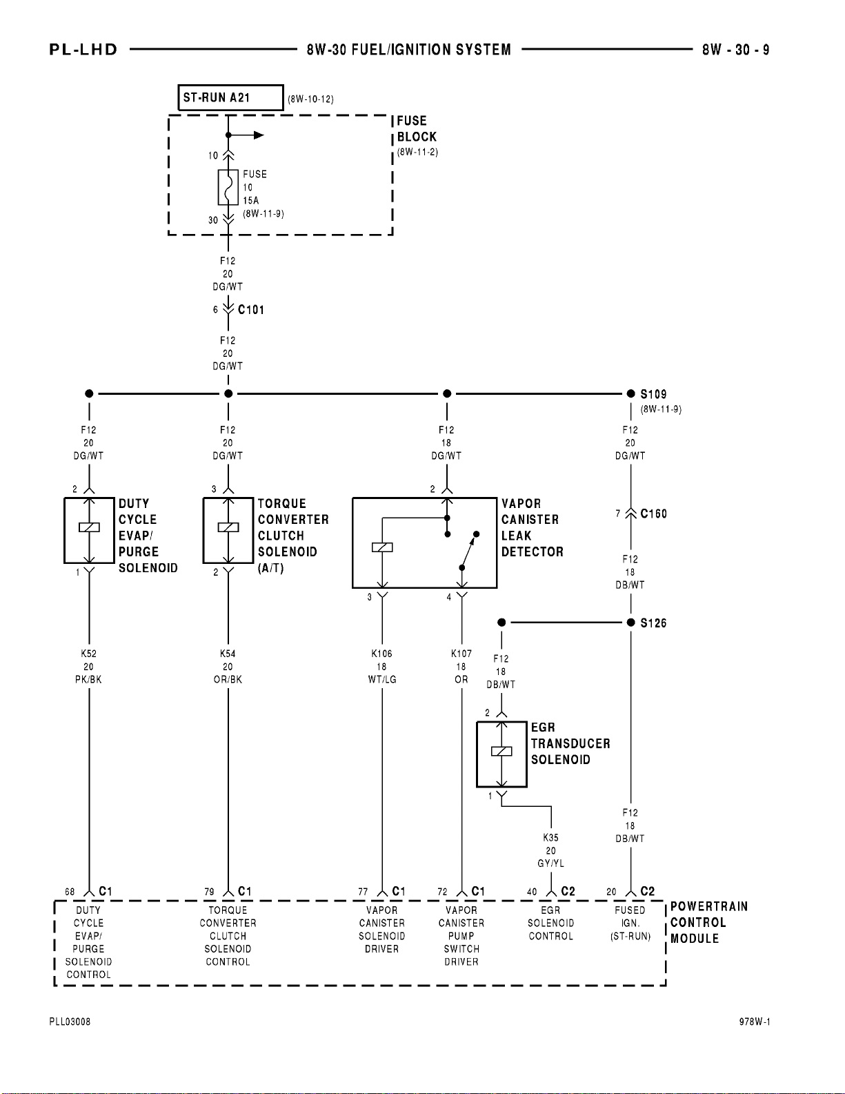
Duty Cycle Evap/Purge Solenoid .........8W-30-9
EGR Transducer Solenoid ..............8W-30-9
Engine Coolant Temperature Sensor ......8W-30-7
Fuel Injector No. 1 ...................8W-30-5
Fuel Injector No. 2 ...................8W-30-5
Fuel Injector No. 3 ...................8W-30-5
Fuel Injector No. 4 ...................8W-30-5
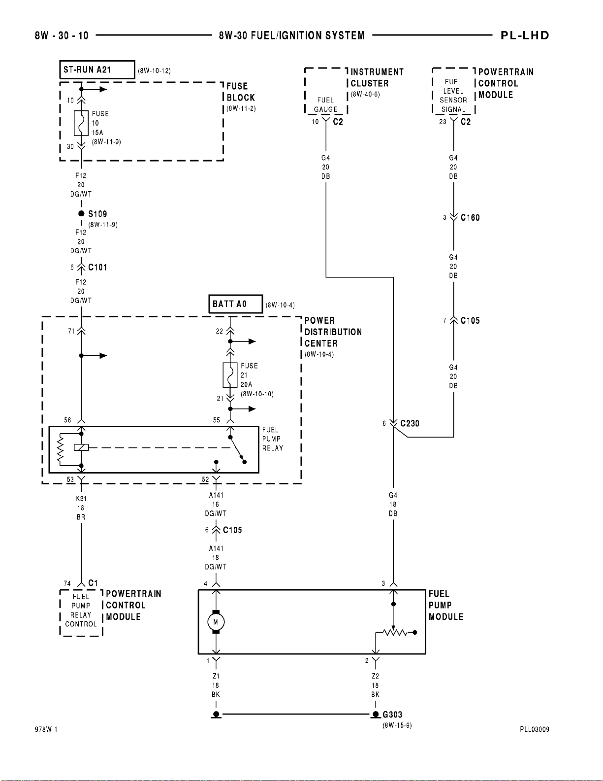
Fuel Pump Module ..................8W-30-10
Fuel Pump Relay ....................8W-30-10
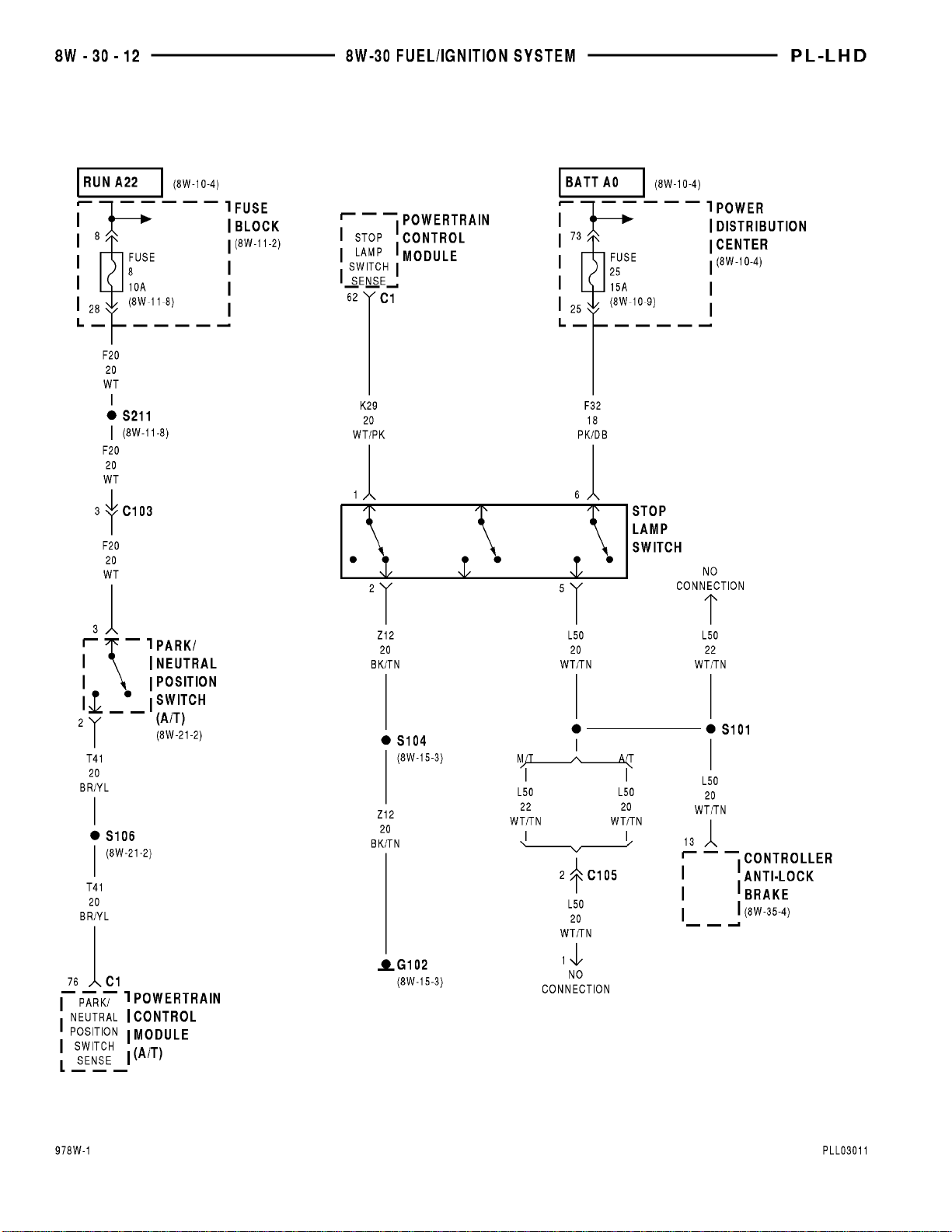
Fuse 8 (FB) ........................8W-30-12
Fuse 10 (FB) .....................8W-30-9, 10
Fuse 21 (PDC) ................8W-30-2, 3, 4, 10
Fuse 25 (PDC) ......................8W-30-12
Fuse Block ....................8W-30-9, 10, 12
G101 ..............................8W-30-3
G102 .........................8W-30-2, 4, 12
G106 ..............................8W-30-2
G303 .............................8W-30-10
Generator .........................8W-30-11
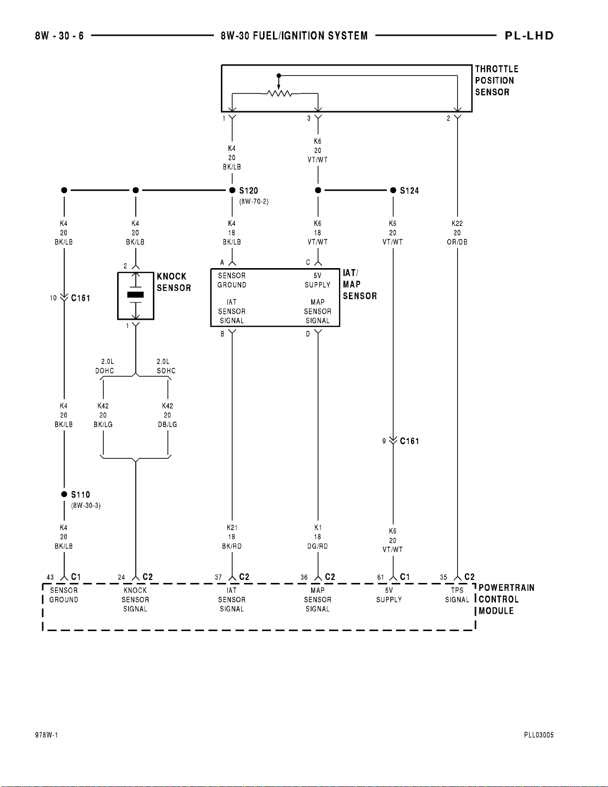
IAT/MAP Sensor .....................8W-30-6
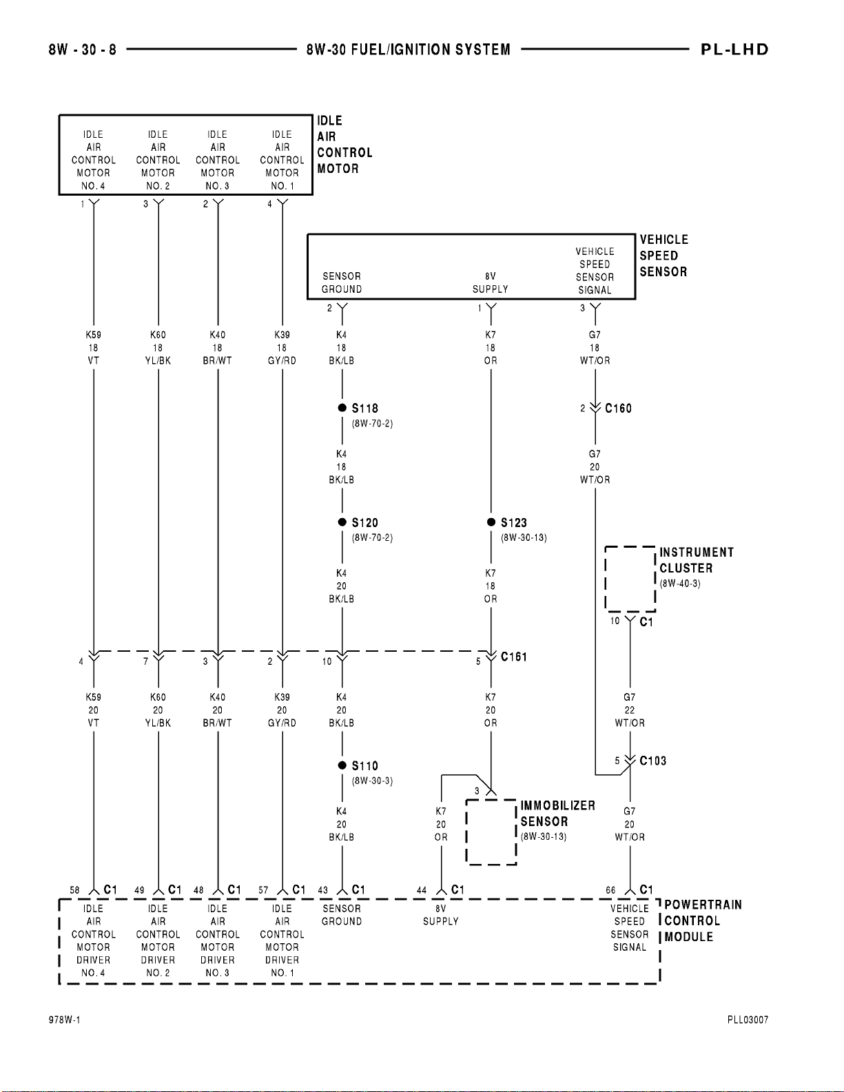
Idle Air Control Motor .................8W-30-8
Ignition Coil Pack ....................8W-30-5
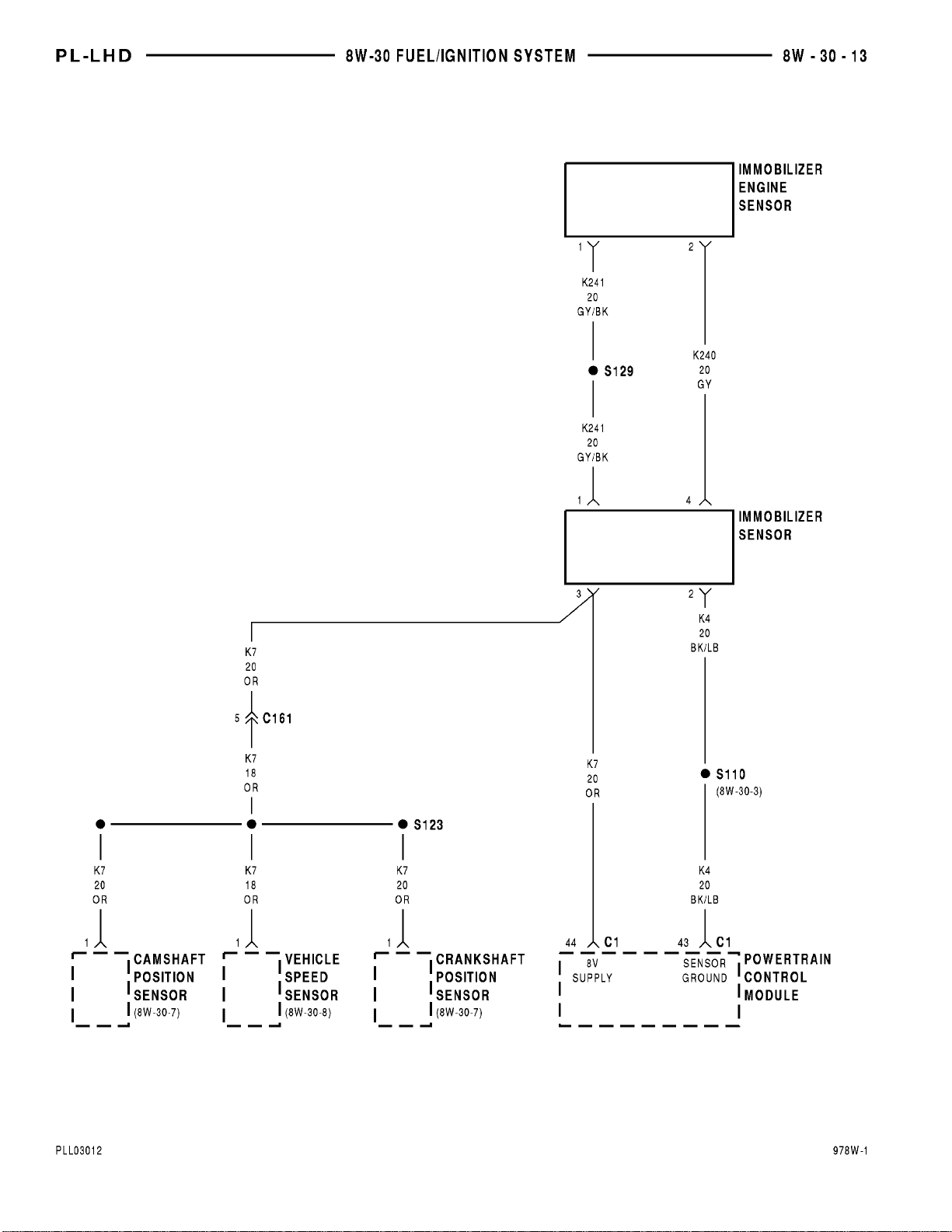
Immobilizer Engine Sensor ............8W-30-13
Immobilizer Sensor ..............8W-30-3, 8, 13
Instrument Cluster ...........8W-30-7, 8, 10, 11
Knock Sensor .......................8W-30-6
Component Page
Noise Supressor .....................8W-30-5
Park/Neutral Position Switch ..........8W-30-12
Power Distribution Center ....8W-30-2, 3, 4, 10, 12
Power Steering Pressure Switch .........8W-30-4
Powertrain Control Module ........8W-30-2, 3, 4,
5, 6, 7, 8, 9, 10, 11, 12, 13
S101 .............................8W-30-12
S102 ..............................8W-30-4
S104 ...........................8W-30-2, 12
S104 ............................8W-30-2, 4
S105 ............................8W-30-2, 4
S106 .............................8W-30-12
S107 ..............................8W-30-3
S109 ...........................8W-30-9, 10
S110......................8W-30-3, 6, 7, 8, 13
S118 ..........................8W-30-3, 7, 8
S119 ..............................8W-30-3
S120 ........................8W-30-3, 6, 7, 8
S121 ..............................8W-30-5
S122 ..........................8W-30-2, 3, 5
S123 .............................8W-30-13
S123 ............................8W-30-7, 8
S124 ..............................8W-30-6
S126 ..............................8W-30-9
S127 ..............................8W-30-3
S129 .............................8W-30-13
S134 ..............................8W-30-5
S211 .............................8W-30-12
Solid State Fan Relay ................8W-30-11
Stop Lamp Switch ...................8W-30-12
Throttle Position Sensor ...............8W-30-6
Torque Converter Clutch Solenoid ........8W-30-9
Upstream Heated Oxygen Sensor ........8W-30-3
Vapor Canister Leak Detector ...........8W-30-9
Vehicle Speed Sensor ...............8W-30-8, 13
Page 68
Page 69
Page 70
Page 71
Page 72
Page 73
Page 74
Page 75
Page 76
Page 77
Page 78
Page 79
Page 80

8W - 30 - 14 8W - 30 FUEL/IGNITION SYSTEMS PL
8W-30 FUEL/IGNITION SYSTEMS
INDEX
page page
DESCRIPTION AND OPERATION
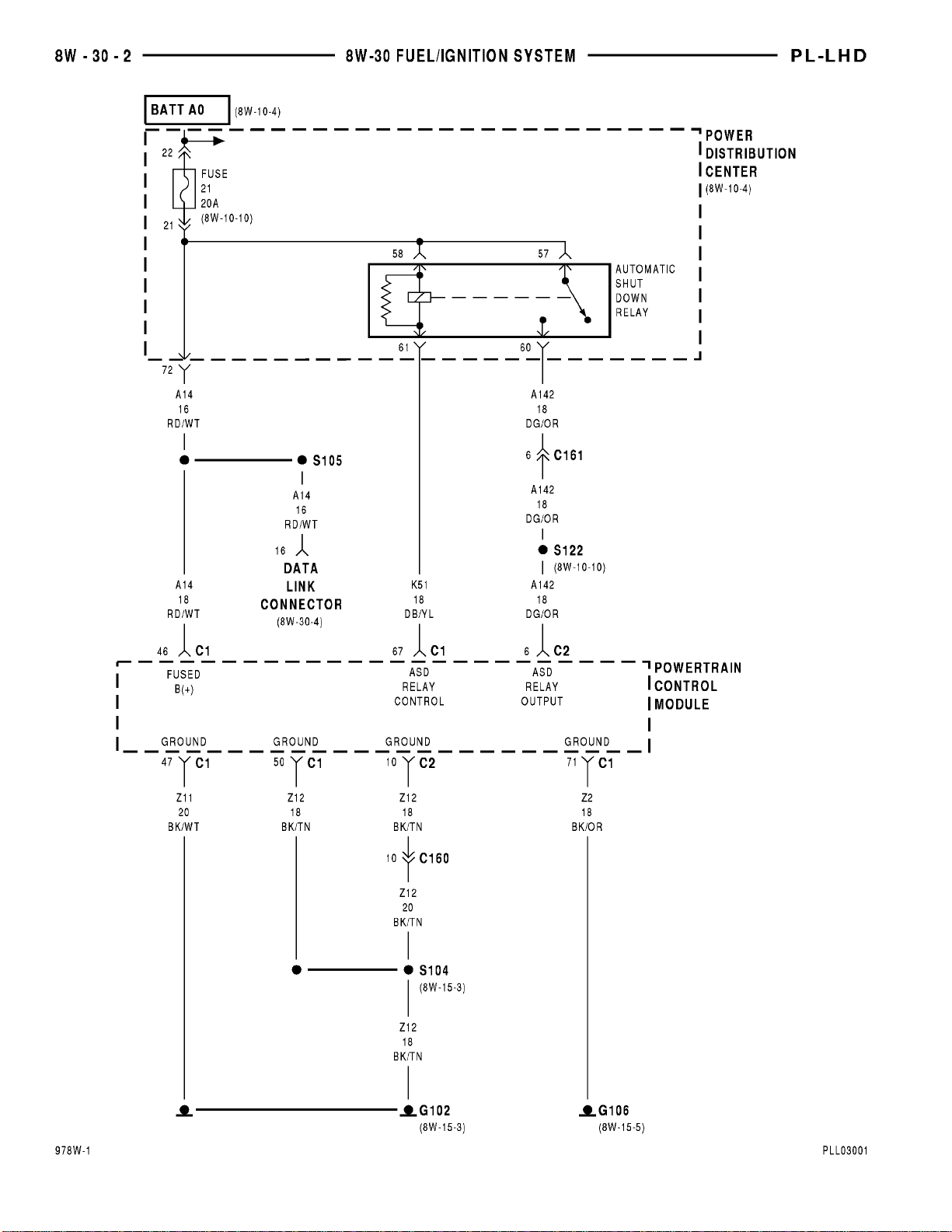
AUTOMATIC SHUT DOWN RELAY .......... 15
BATTERY FEED ........................ 14
BATTERY TEMPERATURE SENSOR ......... 18
CAMSHAFT POSITION SENSOR ........... 16
CRANKSHAFT POSITION SENSOR ......... 16
DATA LINK CONNECTOR ................. 15
DUTY CYCLE EVAP/PURGE SOLENOID ...... 19
EGR TRANSDUCER (EET) SOLENOID ....... 19
ENGINE COOLANT TEMPERATURE SENSOR . 16
FUEL INJECTORS ....................... 18
FUEL PUMP MOTOR .................... 15
HEATED OXYGEN SENSORS .............. 16
IDLE AIR CONTROL MOTOR .............. 18
IGNITION COIL PACK .................... 18
DESCRIPTION AND OPERATION
IGNITION SWITCH
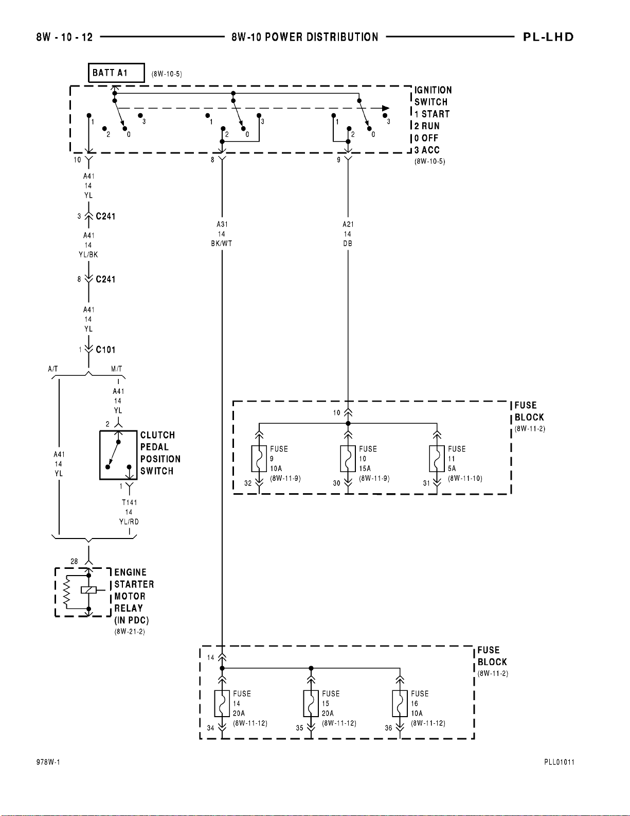
In the RUN position, the ignition switch connects circuit A1 from the Power Distribution Center (PDC) to
circuit A21. A 30 amp fuse in the PDC protects circuits
A1 and A21. Circuit A21 feeds a bus bar in the fuse
block. The bus bar feeds circuits G5, F12, and F15.
•
Circuit G5 powers the gauge cluster warning lamps
and the daytime running lamp (DRL) module. Fuse cavity 11 (5 amp) in the fuse block protects circuit G5.
• Circuit F12 splices to the Powertrain Control
Module (PCM), duty cycle purge solenoid, EGR solenoid, ABS system, and a bus bar in the PDC. The
bus bar in the PDC feeds the coil side of the radiator
fan relay, A/C compressor clutch relay, and the fuel
pump relay. A 15 amp fuse in the fuse block, cavity
10, protects circuit F12.
• Circuit F15 feeds the Airbag Control Module
(ACM). A 10 amp fuse in the fuse block, cavity 9, protects circuit F15.
BATTERY FEED
Circuit A14 from the Power Distribution Center
(PDC) supplies battery voltage to cavity 46 of the
Powertrain Control Module (PCM). A 20 amp fuse in
the PDC protects circuit A14.
HELPFUL INFORMATION
Circuit A14 connects to a bus bar in the PDC that
the battery feeds. Circuit A14 powers the Automatic
Shut Down (ASD) relay and fuel pump relay. The
A14 circuit also splices to the data link connector.
IGNITION SWITCH ...................... 14
INTAKE AIR TEMPERATURE SENSOR ....... 17
KNOCK SENSOR ....................... 17
LOW FUEL DETECT INPUT ............... 19
MANIFOLD ABSOLUTE PRESSURE SENSOR . 17
PARK/NEUTRAL POSITION SWITCH INPUT
(3–SPD TRANSMISSION) ................ 19
POWER (DEVICE) GROUND ............... 14
POWER STEERING PRESSURE SWITCH ..... 19
SIGNAL GROUND ....................... 14
THROTTLE POSITION SENSOR ............ 17
TORQUE CONVERTER CLUTCH SOLENOID
(TCC) ............................... 19
VEHICLE SPEED SENSOR ................ 15
POWER (DEVICE) GROUND
Circuit Z12 connects to cavities 10 and 50 of the
Powertrain Control Module (PCM). The Z12 circuit
provides ground for PCM internal drivers that operate high current devices like the injectors and ignition coils.
Internal to the PCM, the power (device) ground circuit connects to the PCM sensor return circuit (from
circuit K4) and the signal ground circuit (Z11).
HELPFUL INFORMATION
Circuit Z12 which supplies ground for the PCM
high current drivers, has the same termination point
as circuit Z11. The termination point is the left side
of the radiator closure panel.
If the system loses ground for the ganged circuits,
at the left side of the radiator closure panel, the vehicle will not operate. Check the connection at the
ganged ground circuit eyelet.
SIGNAL GROUND
The signal ground circuit Z11 connects to cavity 47
of the PCM. The Z11 circuit provides ground for the
sensors that provide inputs to the PCM. Internal to
the PCM, the signal ground circuit connects to the
PCM sensor return circuit (from circuit K4) and the
power (device) ground circuit (Z12).
The termination point for circuit Z11 is an eyelet
attached to the left side of the radiator closure panel.
HELPFUL INFORMATION
Circuit Z12 which supplies ground for the PCM
high current drivers, has the same termination point
Page 81

PL 8W - 30 FUEL/IGNITION SYSTEMS 8W - 30 - 15
DESCRIPTION AND OPERATION (Continued)
as circuit Z11. The termination point is the left side
of the radiator closure panel.
If the system loses ground for the ganged circuits,
at the left side of the radiator closure panel, the vehicle will not operate. Check the connection at the
ganged ground circuit eyelet.
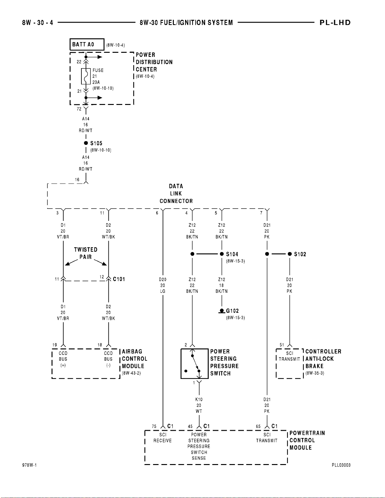
DATA LINK CONNECTOR
Circuit A14 supplies battery voltage to the universal data link connector. Circuit A14 originates in the
Power Distribution Center (PDC) and connects to a
battery fed bus bar. A 20 amp fuse protects circuit
A14.
A twisted pair of wires, circuits D1 and D2, from
the Airbag Control Module (ACM) connect to the universal data link connector.
Ground circuit Z12 splices to two cavities of the
data link connector. The Z12 circuit also connects to
cavities 10 and 50 of the PCM connector.
Circuit D20 connects to cavity 75 of the PCM and
to the universal data link connector. Circuit D20 is
the SCI receive circuit for the PCM.
Circuit D21 connects to cavity 65 of the PCM and
to the universal data link connector. Circuit D21 is
the SCI transmit circuit for the PCM. The D21 circuit splices to the ABS module.
HELPFUL INFORMATION
The grounding point for circuit Z12 is the left side
of the radiator closure panel.
Circuit Z12 also supplies ground for the PCM high
current drivers and has the same termination point
as circuit Z11.
If the system loses ground for the ganged circuits
at the left side radiator closure panel the vehicle will
not operate. Check the connection at the ganged
ground circuit eyelet.
AUTOMATIC SHUT DOWN RELAY
The Automatic Shut Down (ASD) relay is located
in the Power Distribution Center (PDC). Power for
the coil and contact side of the relay is supplied on
circuit A14. This circuit is HOT at all times and protected by a 20 amp fuse located in the PDC.
The Powertrain Control Module (PCM) controls the
ground path for the coil side of the relay on circuit
K51. This circuit connects to cavity 67 of the PCM.
When the PCM supplies the ground path on circuit
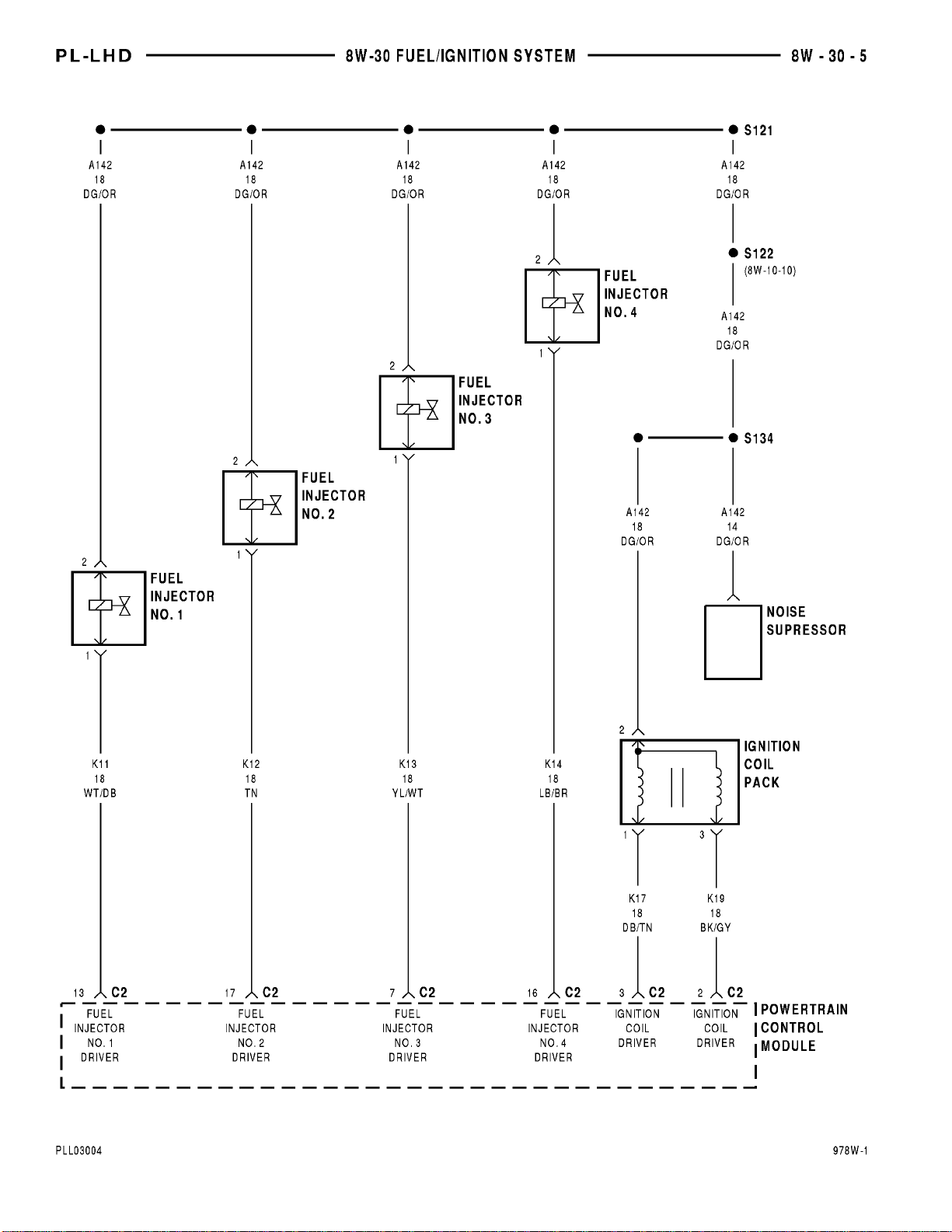
K51 the contacts in the relay CLOSE connecting circuits A14 and A142. The A142 circuit is spliced and
supplies power to the generator, fuel injectors, PCM,
ignition coil, and heated oxygen sensors.
HELPFUL INFORMATION
• Refer to group 14 Fuel System, for additional
information.
• Check the 20 amp fuse located in the PDC.
FUEL PUMP MOTOR
Circuit A14 is a bus bar in the Power Distribution
Center (PDC) and connects to battery voltage. The
contact side of the fuel pump relay connects circuit
A14 and circuit A141. A 20 amp fuse in the PDC protects circuits A14 and A142.
Circuit A141 supplies voltage for the fuel pump
motor. Circuit Z1 provides ground for the fuel pump
motor. The grounding point for circuit Z1 is the right
rear wheel house.
Circuit F12 supplies voltage to the coil side of the
fuel pump relay. The Powertrain Control Module
(PCM) controls the ground path circuit for the coil
side of the fuel pump relay on circuit K31. Circuit
K31 connects to cavity 74 of the PCM.
HELPFUL INFORMATION
Circuit F12 originates in the fuse block where it
connects to a bus bar fed by circuit A21. In the
START and RUN position, the ignition switch connects circuit A1 from the PDC to circuit A21. A 30
amp fuse in the PDC protects circuits A1 and A21.
Circuit F12 splices to feed the ABS control module,
EGR solenoid, Torque Converter Clutch (TCC) solenoid, leak detection pump, and the EVAP/Purge solenoid.
Circuit F12 also connects to a bus bar in the PDC.
The bus bar supplies voltage to the coil side of radiator fan relay and A/C clutch relay, as well as the
fuel pump relay.
VEHICLE SPEED SENSOR
Circuit K7 supplies 8 volts from the Powertrain
Control Module (PCM) to the Vehicle Speed Sensor
(VSS). The K7 circuit connects to cavity 44 of the
PCM connector.
Circuit G7 from the VSS provides an input signal
to the PCM. The G7 circuit connects to cavity 66 of
the PCM connector.
The PCM provides ground for the VSS signal (circuit G7) through circuit K4. Circuit K4 connects to
cavity 43 of the PCM connector.
HELPFUL INFORMATION
Circuit G7 splices to the speedometer and odometer in the instrument cluster.
Circuit K7 splices to supply 8 volts to the camshaft
position sensor and crankshaft position sensor.
Circuit K4 splices to supply ground for the signals
from the following:
• Upstream heated oxygen sensor
• Downstream heated oxygen sensor
• Crankshaft position sensor
• Camshaft position sensor
• Battery temperature sensor
• Throttle position sensor
• Manifold absolute pressure sensor
Page 82

8W - 30 - 16 8W - 30 FUEL/IGNITION SYSTEMS PL
DESCRIPTION AND OPERATION (Continued)
• Engine coolant temperature sensor
• Knock sensor
• Intake air temperature sensor
HEATED OXYGEN SENSORS
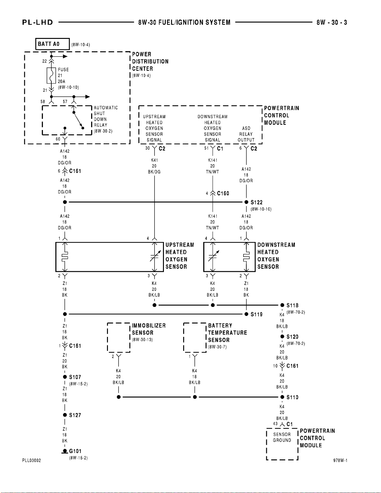
Circuit A14 is a bus bar in the Power Distribution
Center (PDC), and connects to battery voltage. The
contact side of the Automatic Shut Down (ASD) relay
connects circuit A14 and circuit A142. A 20 amp fuse
in the PDC protects circuits A14 and A142.
Circuit A14 also supplies voltage to the coil side of
the ASD relay. The Powertrain Control Module
(PCM) controls the ground path circuit for the coil
side of the ASD relay on circuit K51. Circuit K51 connects to cavity 67 of the PCM connector.
Circuit A142 splices to supply voltage for the
upstream and downstream heated oxygen sensors.
The A142 circuit also splices to cavity 6 of the
PCM. The input provided by circuit A142 at cavity 6
tells the PCM that the ASD relay energized.
Circuit K41 delivers the signal from the upstream
heated oxygen sensor to the PCM. Circuit K41 connects to cavity 30 of the PCM connector.
Circuit K141 delivers the signal from the downstream heated oxygen sensor to the PCM. Circuit
K141 connects to cavity 51 of the PCM connector.
The PCM provides a ground for the upstream and
downstream heated oxygen sensor signals (circuit
K41 and K141) through circuit K4. Circuit K4 connects to cavity 43 of the PCM connector.
Circuit Z1 provides ground for the heater circuits
in each sensor. Circuit Z1 terminates at the left side
of the radiator closure panel.
HELPFUL INFORMATION
Circuit A142 splices to supply voltage to the fuel
injectors, ignition coil, ASD relay, generator, and the
upstream and downstream heated oxygen sensors.
The PCM controls the ground circuit for each of the
components powered by circuit A142.
CRANKSHAFT POSITION SENSOR
Circuit K7 supplies 8 volts from the Powertrain
Control Module (PCM) to the crankshaft position
sensor. The K7 circuit connects to cavity 44 of the
PCM connector.
Circuit K24 from the sensor provides an input signal to the PCM. The K24 circuit connects to cavity 32
of the PCM connector.
The PCM provides ground for the crankshaft position sensor signal (circuit K24) through circuit K4.
Circuit K4 connects to cavity 43 of the PCM connector.
HELPFUL INFORMATION
Circuit K7 splices to supply 8 volts to the camshaft
position sensor and vehicle speed sensor.
Circuit K4 splices to supply ground for the signals
from the following:
• Upstream heated oxygen sensor
• Downstream heated oxygen sensor
• Camshaft position sensor
• Battery temperature sensor
• Throttle position sensor
• Manifold absolute pressure sensor
• Engine coolant temperature sensor
• Knock sensor
• Intake air temperature sensor
• Vehicle speed sensor
CAMSHAFT POSITION SENSOR
Circuit K7 supplies 8 volts from the Powertrain
Control Module (PCM) to the camshaft position sensor. The K7 circuit connects to cavity 44 of the PCM
connector.
Circuit K44 from the sensor provides an input signal to the PCM. The K44 circuit connects to cavity 33
of the PCM connector.
The PCM provides ground for the camshaft position sensor signal (circuit K44) through circuit K4.
Circuit K4 connects to cavity 43 of the PCM connector.
HELPFUL INFORMATION
Circuit K7 splices to supply 8 volts to the camshaft
position sensor and vehicle speed sensor.
Circuit K4 splices to supply ground for the signals
from the following:
• Upstream heated oxygen sensor
• Downstream heated oxygen sensor
• Crankshaft position sensor
• Battery temperature sensor
• Throttle position sensor
• Manifold absolute pressure sensor
• Engine coolant temperature sensor
• Knock sensor
• Intake air temperature sensor
• Vehicle speed sensor
ENGINE COOLANT TEMPERATURE SENSOR
The engine coolant temperature sensor provides an
input to the Powertrain Control Module (PCM) on
circuit K2. The sensor also operates the engine coolant temperature gauge in the instrument cluster on
circuit G20. Refer to Section 8W-40 for coolant temperature gauge circuit description.
From circuit K2 the engine coolant temperature
sensor draws up to 5 volts from the PCM. The sensor
is a variable resistor. As coolant temperature
changes, the resistance in the sensor changes causing
a change in current draw. The K2 circuit connects to
cavity 26 of the PCM connector.
The PCM provides ground for the engine coolant
temperature sensor signal (circuit K2) through circuit
Page 83

PL 8W - 30 FUEL/IGNITION SYSTEMS 8W - 30 - 17
DESCRIPTION AND OPERATION (Continued)
K4. Circuit K4 connects to cavity 43 of the PCM connector.
HELPFUL INFORMATION
The engine coolant temperature sensor is case
grounded. The case ground provides the ground for
the coolant temperature gauge circuit G20.
Circuit K4 splices to supply ground for the signals
from the following:
• Upstream heated oxygen sensor
• Downstream heated oxygen sensor
• Camshaft position sensor
• Crankshaft position sensor
• Battery temperature sensor
• Throttle position sensor
• Manifold absolute pressure sensor
• Knock sensor
• Intake air temperature sensor
• Vehicle speed sensor
THROTTLE POSITION SENSOR
From the Powertrain Control Module (PCM), circuit K6 supplies 5 volts to the Throttle Position Sensor (TPS). Circuit K6 connects to cavity 61 of the
PCM connector.
Circuit K22 delivers the TPS signal to the PCM.
Circuit K22 connects to cavity 35 of the PCM connector.
The PCM provides ground for the TPS signal (circuit K22) through circuit K4. Circuit K4 connects to
cavity 43 of the PCM connector.
HELPFUL INFORMATION
Refer to Group 14 for TPS operation.
Circuit K6 splices to supply 5 volts to the Manifold
Absolute Pressure (MAP) sensor.
Circuit K4 splices to supply ground for the signals
from the following:
• Upstream heated oxygen sensor
• Downstream heated oxygen sensor
• Battery temperature sensor
• Camshaft position sensor
• Crankshaft position sensor
• Engine coolant temperature sensor
• Manifold absolute pressure sensor
• Knock sensor
• Intake air temperature sensor
• Vehicle speed sensor
MANIFOLD ABSOLUTE PRESSURE SENSOR
From the Powertrain Control Module (PCM), circuit K6 supplies 5 volts to the Manifold Absolute
Pressure (MAP) sensor. Circuit K6 connects to cavity
61 of the PCM connector.
Circuit K1 delivers the MAP signal to the PCM.
Circuit K1 connects to cavity 36 of the PCM connector.
The PCM provides ground for the MAP sensor signal (circuit K1) through circuit K4. Circuit K4 connects to cavity 43 of the PCM connector.
HELPFUL INFORMATION
Refer to Group 14 for MAP sensor operation.
Circuit K6 splices to supply 5 volts to the Throttle
Position Sensor.
Circuit K4 splices to supply ground for the signals
from the following:
• Upstream heated oxygen sensor
• Downstream heated oxygen sensor
• Battery temperature sensor
• Camshaft position sensor
• Crankshaft position sensor
• Engine coolant temperature sensor
• Throttle position sensor
• Knock sensor
• Intake air temperature sensor
• Vehicle speed sensor
INTAKE AIR TEMPERATURE SENSOR
The intake air temperature sensor provides an
input to the Powertrain Control Module (PCM) on
circuit K21. Circuit K21 connects to cavity 37 of the
PCM connector.
From circuit K21 the intake air temperature sensor draws voltage from the PCM. The sensor is a
variable resistor. As intake air temperature changes,
the resistance in the sensor changes causing a
change in current draw.
The PCM provides ground for the intake air temperature sensor signal (circuit K21) through circuit
K4. Circuit K4 connects to cavity 43 of the PCM connector.
HELPFUL INFORMATION
Circuit K4 splices to supply ground for the signals
from the following:
• Upstream heated oxygen sensor
• Downstream heated oxygen sensor
• Battery temperature sensor
• Camshaft position sensor
• Crankshaft position sensor
• Engine coolant temperature sensor
• Throttle position sensor
• Knock sensor
• Manifold absolute pressure sensor
• Vehicle speed sensor
KNOCK SENSOR
The knock sensor provides an input to the Powertrain Control Module (PCM) on circuit K42. Circuit
K42 connects to cavity 24 of the PCM connector.
The PCM provides ground for the knock sensor signal (circuit K42) through circuit K4. Circuit K4 connects to cavity 43 of the PCM connector.
Page 84

8W - 30 - 18 8W - 30 FUEL/IGNITION SYSTEMS PL
DESCRIPTION AND OPERATION (Continued)
HELPFUL INFORMATION
Circuit K4 splices to supply ground for the signals
from the following:
• Upstream heated oxygen sensor
• Downstream heated oxygen sensor
• Battery temperature sensor
• Camshaft position sensor
• Crankshaft position sensor
• Engine coolant temperature sensor
• Throttle position sensor
• Intake air temperature sensor
• Manifold absolute pressure sensor
• Vehicle speed sensor
BATTERY TEMPERATURE SENSOR
From circuit G31 the battery temperature sensor
draws voltage from the Powertrain Control Module
(PCM). The sensor is a variable resistor. As battery
temperature changes, the resistance in the sensor
changes causing a change in current draw. Circuit
G31 connects to cavity 52 of the PCM connector.
The PCM provides ground for the battery temperature sensor signal (circuit G31) through circuit K4.
Circuit K4 connects to cavity 43 of the PCM connector.
HELPFUL INFORMATION
Circuit K4 splices to supply ground for the signals
from the following:
• Upstream heated oxygen sensor
• Downstream heated oxygen sensor
• Camshaft position sensor
• Crankshaft position sensor
• Engine coolant temperature sensor
• Throttle position sensor
• Manifold absolute pressure sensor
• Knock sensor
• Intake air temperature sensor
• Vehicle speed sensor
FUEL INJECTORS
Circuit A14 is a bus bar in the Power Distribution
Center (PDC), and connects to battery voltage. The
contact side of the Automatic Shut Down (ASD) relay
connects circuit A14 and circuit A142. A 20 amp fuse
in the PDC protects circuits A14 and A142.
Circuit A14 also supplies voltage to the coil side of
the ASD relay. The Powertrain Control Module
(PCM) controls the ground circuit for the coil side of
the ASD relay on circuit K51. Circuit K51 connects to
cavity 67 of the PCM connector.
Circuit A142 supplies voltage for the fuel injectors.
The PCM controls the ground circuit of each injector.
• Circuit K11 is the ground circuit for Injector #1.
Circuit K11 connects to cavity 13 of the PCM.
• Circuit K12 is the ground circuit for Injector #2.
Circuit K12 connects to cavity 17 of the PCM.
• Circuit K13 is the ground circuit for Injector #3.
Circuit K13 connects to cavity 7 of the PCM.
• Circuit K14 is the ground circuit for Injector #4.
Circuit K14 connects to cavity 16 of the PCM.
HELPFUL INFORMATION
Circuit A142 splices to supply voltage to the fuel
injectors, ignition coil, ASD relay, generator, and the
upstream and downstream heated oxygen sensors.
The PCM controls the ground circuit for each of the
components powered by circuit A142.
The injectors operate in sequence. Refer to Group
14 for system operation.
IGNITION COIL PACK
Circuit A14 is a bus bar in the Power Distribution
Center (PDC), and connects to battery voltage. The
contact side of the Automatic Shut Down (ASD) relay
connects circuit A14 and circuit A142. A 20 amp fuse
in the PDC protects circuits A14 and A142.
Circuit A14 also supplies voltage to the coil side of
the ASD relay. The Powertrain Control Module
(PCM) controls the ground path circuit for the coil
side of the ASD relay on circuit K51. Circuit K51 connects to cavity 67 of the PCM connector.
Circuit A142 supplies voltage for the ignition coil
pack. The coil pack consists of two individual coils
molded together. The PCM controls the ground circuit of each coil.
• Circuit K19 is the ground circuit for the ignition
coil that fires spark plugs # 1 and # 4. Circuit K19
connects to cavity 2 of the PCM.
• Circuit K17 is the ground circuit for the ignition
coil that fires spark plugs #2 and # 3. Circuit K17
connects to cavity 3 of the PCM.
HELPFUL INFORMATION
Circuit A142 splices to supply voltage to the fuel
injectors, ignition coil, ASD relay, generator,
upstream heated oxygen sensor and downstream
heated oxygen sensor. The PCM controls the ground
circuit for each of the components powered by circuit
A142.
IDLE AIR CONTROL MOTOR
The Powertrain Control Module (PCM) operates
the Idle Air Control (IAC) motor through 4 circuits K39, K40, K59, and K60. Each circuit connects to
separate cavities in the PCM connector.
• Circuit K39 connects to cavity 57 of the PCM
connector.
• Circuit K40 connects to cavity 48 of the PCM
connector.
• Circuit K59 connects to cavity 58 of the PCM
connector.
• Circuit K60 connects to cavity 49 of the PCM
connector.
Page 85

PL 8W - 30 FUEL/IGNITION SYSTEMS 8W - 30 - 19
DESCRIPTION AND OPERATION (Continued)
POWER STEERING PRESSURE SWITCH
The power steering pressure switch opens and
closes circuit K10 between the Powertrain Control
Module (PCM) and ground. Circuit K10 connects to
cavity 45 of the PCM connector.
Circuit Z12 provides ground for the power steering
pressure switch. The grounding point for circuit Z12
is the left side of the radiator closure panel.
TORQUE CONVERTER CLUTCH SOLENOID (TCC)
The Powertrain Control Module (PCM) operates
the TCC solenoid by providing a ground path on circuit K54. Circuit K54 connects to PCM cavity 79.
Circuit F12 supplies battery voltage to the TCC
solenoid. Circuit F12 connects to a bus bar in the
fuse block fed by circuit A21. A 15 amp fuse in the
fuse block, cavity 10, protects circuit F12. Circuit F12
connects to cavity 20 of the PCM connector.
HELPFUL INFORMATION
Circuit F12 splices to feed the ABS control module,
PCM, EGR solenoid, leak detection pump, and the
duty cycle EVAP/Purge solenoid. The F12 circuit also
connects to a bus bar in the PDC that supplies voltage to the coil side of radiator fan relay, A/C clutch
relay, and fuel pump relay.
In the RUN or START position, the ignition switch
connects circuit A1 from the fuse block and circuit
A21. Circuit A1 connects to battery voltage and is
protected by a 30 amp fuse in the PDC.
DUTY CYCLE EVAP/PURGE SOLENOID
Circuit F12 supplies battery voltage to the Duty
Cycle EVAP/Purge solenoid. The Powertrain Control
Module (PCM) switches ground path for the solenoid
ON and OFF through circuit K52.
Circuit F12 connects to a bus bar in the fuse block
fed by circuit A21. A 15 amp fuse in the fuse block,
cavity 10, protects circuit F12. Circuit F12 also connects to cavity 20 of the PCM connector.
Circuit K52 connects to cavity 68 of the PCM, and
cavity 1 of the solenoid connector.
HELPFUL INFORMATION
Circuit F12 splices to feed the ABS control module,
PCM, EET solenoid, leak detection pump, and the
TCC solenoid. The F12 circuit also connects to a bus
bar in the PDC that supplies voltage to the coil side
of radiator fan relays, A/C clutch relay, and fuel
pump relay.
In the START or RUN position, the ignition switch
connects circuit A1 from the fuse block and circuit
A21. Circuit A1 connects to battery voltage and is
protected by a 30 amp fuse in the PDC.
EGR TRANSDUCER (EET) SOLENOID
Circuit F12 supplies battery voltage to the EET
solenoid. The Powertrain Control Module (PCM)
switches ground path for the solenoid ON and OFF
through circuit K35.
Circuit F12 connects to a bus bar in the fuse block
fed by circuit A21. A 15 amp fuse in the fuse block,
cavity 10, protects circuit F12. Circuit F12 also connects to cavity 20 of the PCM.
Circuit K35 connects to cavity 40 of the PCM connector.
HELPFUL INFORMATION
Circuit F12 splices to feed the ABS control module,
PCM, Duty Cycle EVAP/Purge solenoid, leak detection pump, and the TCC solenoid. The F12 circuit
also connects to a bus bar in the PDC that supplies
voltage to the coil side of radiator fan relays, A/C
clutch relay, and fuel pump relay.
In the START or RUN position, the ignition switch
connects circuit A1 from the fuse block and circuit
A21. Circuit A1 connects to battery voltage and is
protected by a 30 amp fuse in the PDC.
LOW FUEL DETECT INPUT
Circuit G4 provides an input to the Powertrain
Control Module (PCM) indicating fuel tank level.
This circuit connects to cavity 23 of the PCM connector.
The G4 circuit is also used for the fuel gauge
located in the instrument cluster. For operation of
the fuel gauge, refer to section 8W-40.
PARK/NEUTRAL POSITION SWITCH INPUT (3–SPD TRANSMISSION)
On vehicles equipped with the 3–spd automatic
transmission the park/neutral switch provides an
input to the Powertrain Control Module (PCM).
When CLOSED, the park/neutral position switch
provides a ground path on circuit T41 for the coil
side of the engine starter motor relay. The case
grounded switch provides ground for circuit T41.
Circuit A41 from the ignition switch provides battery voltage to the coil side of the relay.
Circuit T41 splices to cavity 76 of the PCM. The
park/neutral position switch provides an input to the
Powertrain Control Module (PCM).
HELPFUL INFORMATION
In the START position, the ignition switch connects
circuit A1 from the Power Distribution Center (PDC)
to circuit A41. A 30 amp fuse protects circuits A1 and
A41.
Page 86

Page 87

PL 8W - 35 ANTI-LOCK BRAKES 8W - 35 - 1
8W-35 ANTI-LOCK BRAKES
INDEX
page
SCHEMATICS AND DIAGRAMS ........................................................... 1
DESCRIPTION AND OPERATION .......................................................... 6
Component Page
ABS Hydraulic Modulator ..............8W-35-4
ABS Pump Motor ....................8W-35-3
ABS Pump Motor Relay .............8W-35-2, 3
ABS Relay Box ....................8W-35-2, 3
ABS System Relay ...................8W-35-2
ABS Warning Lamp ..................8W-35-2
Controller Anti-Lock Brake .......8W-35-2, 3, 4, 5
Data Link Connector ..................8W-35-3
Fuse 10 (FB) ........................8W-35-2
Fuse 10 (PDC) .......................8W-35-3
Fuse 25 (PDC) .......................8W-35-4
Fuse Block .........................8W-35-2
G101 ..........................8W-35-2, 3, 4
G102 ..............................8W-35-4
Component Page
Instrument Cluster ...................8W-35-2
Left Front Wheel Speed Sensor ..........8W-35-5
Left Rear Wheel Speed Sensor ..........8W-35-5
Power Distribution Center ...........8W-35-3, 4
Pump Motor Driver ...................8W-35-3
Right Front Wheel Speed Sensor ........8W-35-5
Right Rear Wheel Speed Sensor .........8W-35-5
S101 ..............................8W-35-4
S103 ..............................8W-35-3
S104 ..............................8W-35-4
S108 ..........................8W-35-2, 3, 4
S109 ..............................8W-35-2
S210 ..............................8W-35-3
Stop Lamp Switch ....................8W-35-4
Page 88
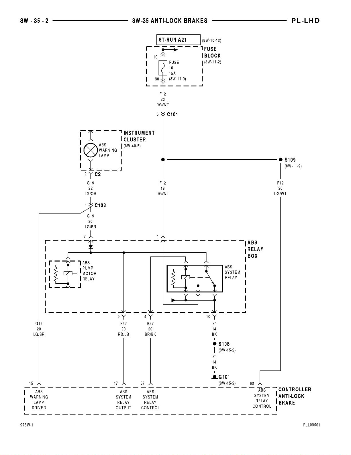
Page 89
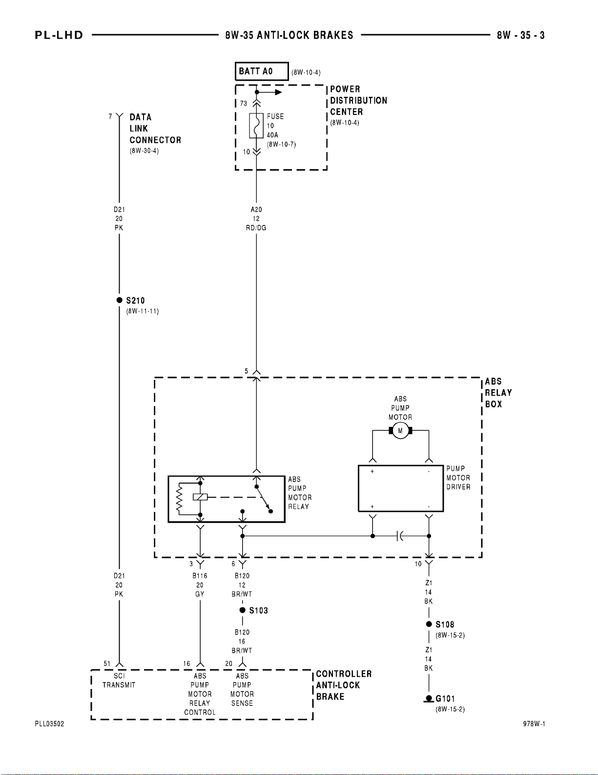
Page 90
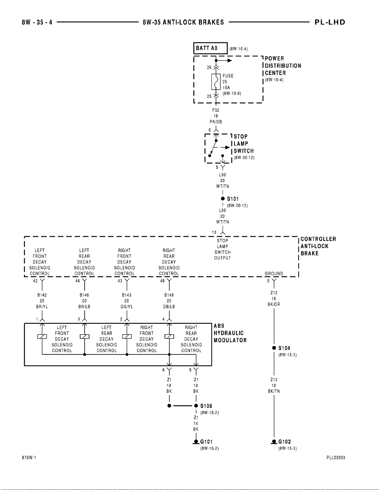
Page 91
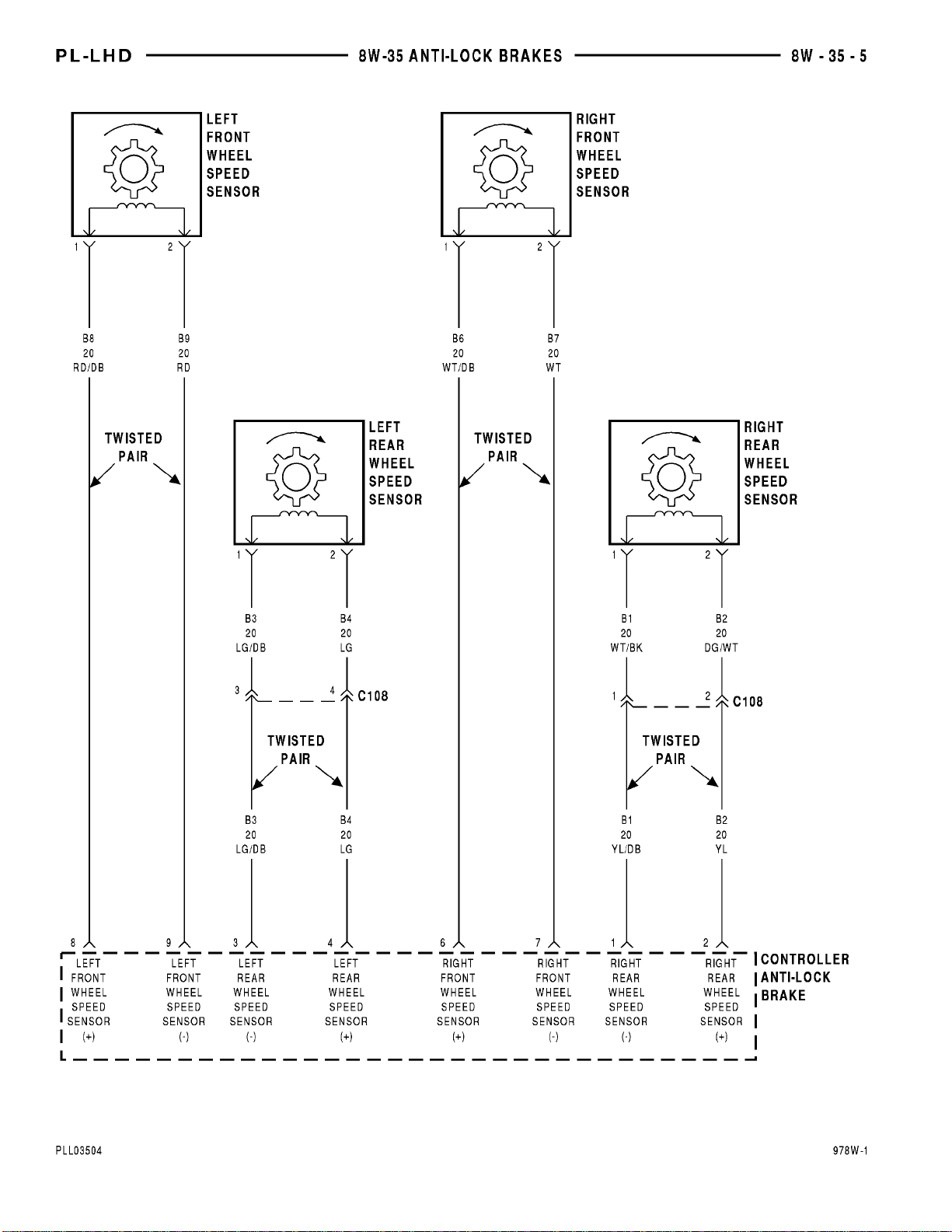
Page 92

8W - 35 - 6 8W - 35 ANTI-LOCK BRAKES PL
8W-35 ANTI-LOCK BRAKES
INDEX
page page
DESCRIPTION AND OPERATION
ABS PUMP MOTOR RELAY ................ 6
ABS SYSTEM RELAY ..................... 6
ABS WARNING LAMP ..................... 6
ANTI-LOCK BRAKES ..................... 6
DESCRIPTION AND OPERATION
ANTI-LOCK BRAKES
Power for the Anti-Lock brake system is supplied
by two fuses. There is a 15 amp fuse located in the
fuse block cavity 10. This fuse supplies power to the
Controller Anti Lock Brake (CAB), and the ABS system relay on the F12 circuit. The F12 circuit also
supplies power to the Powertrain Control Module
(PCM). Power for the fuse is supplied on the A21 circuit from the ignition switch. This fuse is HOT in the
START/RUN position.
The second fuse is located in the Power Distribution Center (PDC). It is a 40 amp fuse. This fuse is
HOT at all times and supplies power to the contact
side of the ABS pump motor relay.
There are three grounding points used in the ABS
system. One is a case ground on the CAB. The second is the Z12 circuit at the CAB connector cavity 5.
This ground is spliced, and terminates at the left side
of the radiator closure panel.
The third ground is on the Z1 circuit. This ground
is used for the ABS hydraulic modulator, ABS system
relay, and the ABS pump motor. This ground, like the
Z12 ground splices and terminates at the left headlamp ground.
Additional information on the circuit function of
the ABS system is listed below. For diagnostic and
testing procedures, refer to the appropriate section of
the Service Manual or the Diagnostic Test Procedures Manual.
ABS WARNING LAMP
The ABS warning lamp is an output from the Controller Anti Lock Brake (CAB) and the ABS relay
box. It is used to alert the operator of a problem in
the ABS system. The G19 circuit from the CAB and
the ABS system relay is used to detect a problem. If
a problem is detected, the CAB grounds the G19 circuit and illuminates the lamp in the instrument cluster.
Circuit G19 is also an output of the CAB to the
ABS system relay contact side.
BRAKE SWITCH INPUT ................... 7
DATA LINK CONNECTOR .................. 7
HELPFUL INFORMATION .................. 7
HYDRAULIC MODULATOR ................. 6
WHEEL SPEED SENSORS ................. 7
ABS SYSTEM RELAY
The system relay is used for the operation of the
ABS system. Power for the relay is supplied on the
B57 circuit from cavity 57 of the Controller Anti Lock
Brake (CAB).
Ground for the relay is on the Z1 circuit. This
ground is spliced in with the pump motor and terminates at the left headlamp ground.
When the system is operating normally power for
the contact side of the relay is supplied from the
CAB on the B57 circuit. It passes through the relay
to the Z1 ground and terminates at the left headlamp
ground. If a problem is detected in the system, the
contact side of the relay switches from the Z1 to the
F12 circuit. This causes the ABS warning lamp in
the instrument cluster to illuminate.
ABS PUMP MOTOR RELAY
The ABS pump motor relay controls when the
pump motor runs. Power for the coil side of the relay
is supplied from cavity 47 of the Controller Anti Lock
Brake (CAB) on the B47 circuit. This circuit also supplies voltage for the contact side of the system relay.
The ground side of the coil is controlled by the B116
circuit. Circuit B116 connects to cavity 16 of the CAB
connector.
Circuit B120 from cavity 20 of the CAB connector
powers the ABS pump motor. This circuit is also used
as an input to the CAB for pump motor monitoring.
HYDRAULIC MODULATOR
The hydraulic modulator is used for the controlling
of the brake system pressure to the wheels. The modulator is made up of four solenoids.
Circuits involved are, B142 for the left front wheel,
B143 for the right front wheel, B146 for the left rear
wheel, and B148 for the right rear wheel.
The solenoids use a common ground on the Z1 circuit. There are two Z1 circuits from the modulator.
Both of these grounds terminate at the left headlamp
ground, and are spliced in with the ABS pump motor
and the ABS system relay.
Page 93

PL 8W - 35 ANTI-LOCK BRAKES 8W - 35 - 7
DESCRIPTION AND OPERATION (Continued)
WHEEL SPEED SENSORS
There are four wheel speed sensors, one at each
wheel. The sensors use a tone wheel to determine
wheel speed. Input to the Controller Anti Lock Brake
(CAB) is done on the following circuits. All of these
circuits are a twisted pair.
B8 and B9 for the left front wheel (cavity 8 and
cavity 9).
B6 and B7 for the right front wheel (cavity 6 and
cavity 7).
B3 and B4 for the left rear wheel (cavity 3 and cavity 4).
B1 and B2 for the right rear wheel (cavity 1 and
cavity 2).
BRAKE SWITCH INPUT
Circuit L50 is an input to the Controller Anti Lock
Brake (CAB). The L50 connects to cavity 13 of the
CAB connector. Circuit L50 is spliced in with the
stop lamps and is used to provide the CAB with
information on when the brakes are being applied.
DATA LINK CONNECTOR
Circuit D21 is used for diagnostics of a fault with
the ABS system. It is spliced in with the Powertrain
Control Module (PCM) circuits and used as an output
from the Controller Anti Lock Brake (CAB). Circuit
D21 connects to cavity 51 of the CAB connector.
HELPFUL INFORMATION
• Check the 15 amp fuse located in cavity 10 of
the fuse block.
• Check the 40 amp fuse located in the PDC.
• Check for a good ground at the left headlamp
ground.
• Check the case ground on the CAB
• Refer to the appropriate section of the service
manual, or the Diagnostic Test Procedures Manual.
Page 94

Page 95

PL 8W - 40 INSTRUMENT CLUSTER 8W - 40 - 1
8W-40 INSTRUMENT CLUSTER
INDEX
page
SCHEMATICS AND DIAGRAMS ........................................................... 1
DESCRIPTION AND OPERATION .......................................................... 7
Component Page
ABS Relay Box ......................8W-40-5
Airbag Control Module ................8W-40-5
Airbag Warning Lamp .................8W-40-5
Anti-Lock Warning Lamp ..............8W-40-5
Brake Warning Lamp .................8W-40-5
Brake Warning Lamp Switch ...........8W-40-5
Charge Indicator Lamp ................8W-40-5
Check Engine Lamp ..................8W-40-6
Cluster Illumination Lamps ............8W-40-2
Controller Anti-Lock Brake .............8W-40-5
Door Ajar Lamp .....................8W-40-5
Engine Coolant Temperature Gauge ......8W-40-6
Engine Coolant Temperature Sensor ......8W-40-6
Engine Oil Pressure Switch ............8W-40-6
Fuel Gauge .........................8W-40-6
Fuel Pump Module ...................8W-40-6
Fuse 11 (FB) ........................8W-40-6
Fuse 12 (FB) ........................8W-40-2
Fuse 13 (PDC) .......................8W-40-3
Fuse Block ........................8W-40-2, 6
G101 ..............................8W-40-5
G204 ..............................8W-40-6
Headlamp Dimmer And
Optical Horn Switch ................8W-40-2
Headlamp Switch ..................8W-40-2, 3
High Beam Indicator Lamp .............8W-40-2
Instrument Cluster ...........8W-40-2, 3, 4, 5, 6
Key-In Switch .......................8W-40-3
Component Page
Left Front Door Jamb Switch ...........8W-40-3
Left Park/Turn Signal Lamp ............8W-40-4
Left Repeater Lamp ..................8W-40-4
Left Turn Indicator Lamp ..............8W-40-4
Low Oil Pressure Lamp ...............8W-40-6
Park Brake Switch ...................8W-40-5
Power Distribution Center .............8W-40-3
Powertrain Control Module .........8W-40-3, 5, 6
Right Park/Turn Signal Lamp ...........8W-40-4
Right Repeater Lamp .................8W-40-4
Right Turn Indicator Lamp .............8W-40-4
S107 ..............................8W-40-5
S112 ..............................8W-40-4
S116 ..............................8W-40-4
S127 ..............................8W-40-5
S201 ..............................8W-40-6
S203 ..............................8W-40-3
S207 ..............................8W-40-4
S208 ..............................8W-40-5
S209 ..............................8W-40-2
S210 ..............................8W-40-2
S212 ..............................8W-40-4
Seat Belt Warning Lamp ...............8W-40-5
Time Out Relay ......................8W-40-5
Turn Signal/Hazard Switch .............8W-40-4
Vehicle Speed Sensor ..................8W-40-3
Page 96
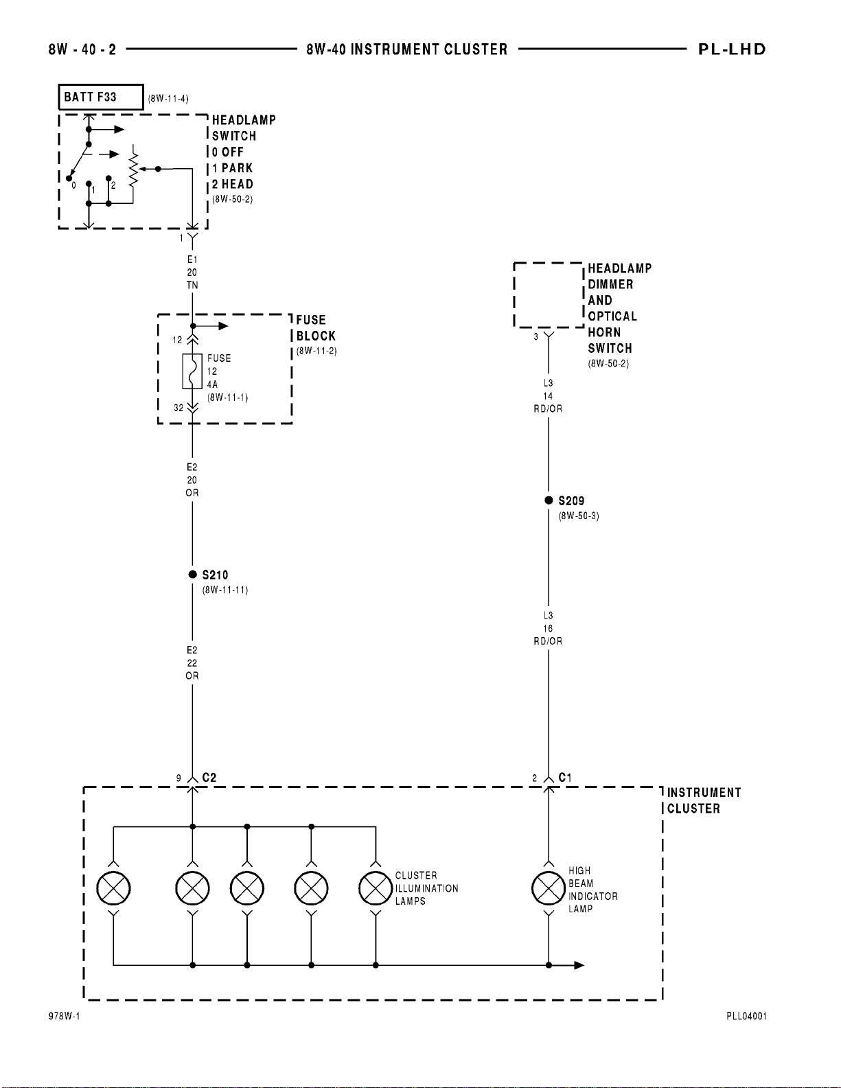
Page 97
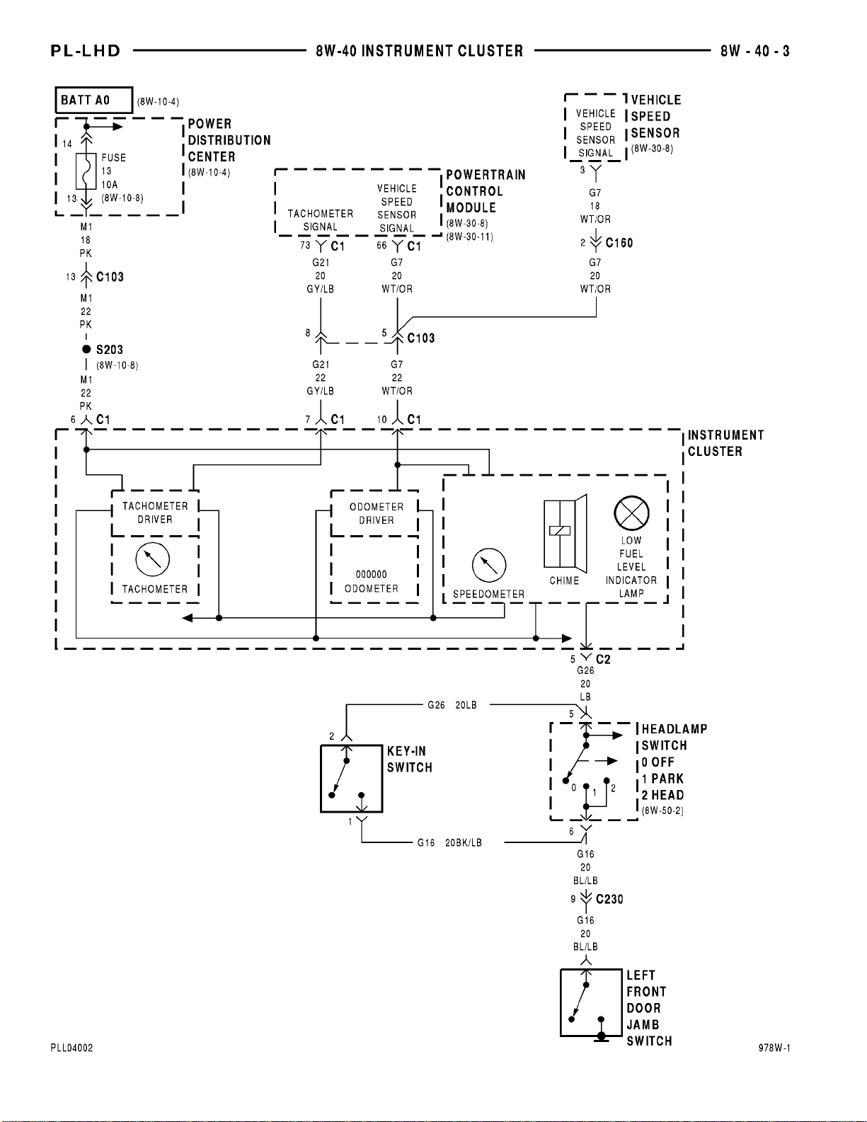
Page 98
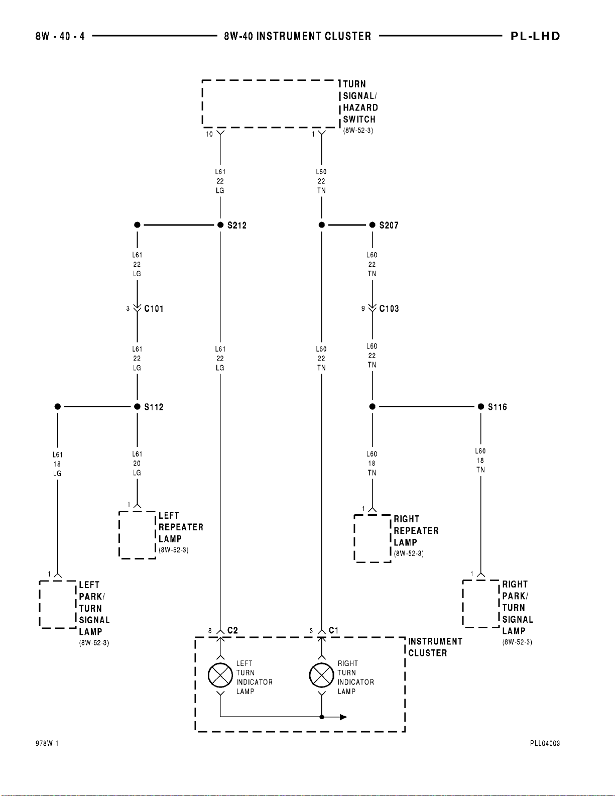
Page 99
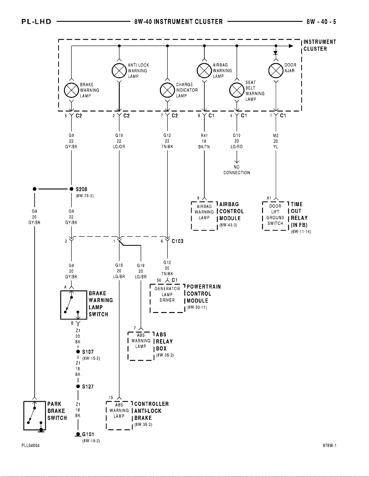
Page 100
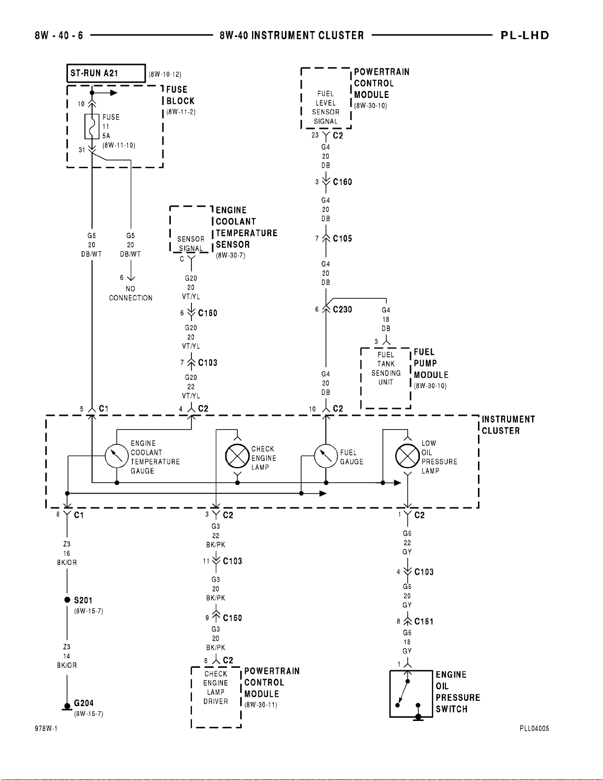
 Loading...