

Page 1
PL POWER MIRRORS 8T - 1
POWER MIRRORS
CONTENTS
page page
GENERAL INFORMATION
INTRODUCTION ........................ 1
DIAGNOSIS AND TESTING
MIRROR MOTOR ........................ 2
MIRROR SWITCH TEST .................. 2
GENERAL INFORMATION
INTRODUCTION
Electrically operated power mirrors are available
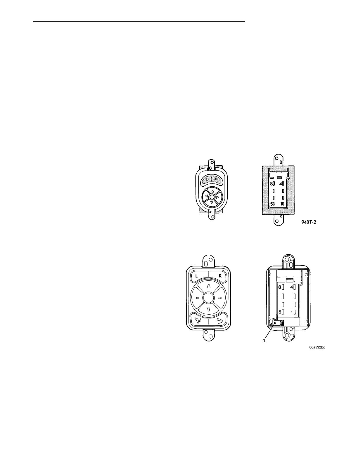
on all car lines. The mirrors are controlled by a single switch assembly located on the driver’s door trim
panel. The push button rocker switch uses L (left)
and R (right) for mirror selection and a button to
push for the desired direction of mirror movement
(Fig. 1).
The motors which operate the mirrors are part of
the mirror assembly and cannot be replaced separately.
Right Hand Drive (RHD) vehicles may be equipped
with Power Fold Away Mirrors. The mirror is controlled the same way as the Left Hand Drive (LHD)
vehicle. The RHD vehicle has an additional switch in
the switch pod that controls the folding function of
the mirror assembly (Fig. 2).
All vehicles are equipped with a Ignition-Off Draw
Fuse, and they are disconnected when the vehicles
are originally shipped from the factory. Disconnecting
this fuse will help prevent the battery from discharge
during storage. The fuse is located in Power Distribution Center (PDC) refer to the cover for proper
location.
This fuse is included in the power mirror circuity
and should be checked if the mirrors are inoperative.
The RHD vehicle mirror circuitry is powered from
the accessory feed circuit and protected by a 15 amp
circuit breaker and power mirror relay. The relay
provides for the switching of the mirror. The circuit
breaker and mirror relay are located in the inner
door panel wire harness.
NOTE: This group covers both Left-Hand Drive
(LHD) and Right-Hand Drive (RHD) versions of this
model. Whenever required and feasible, the RHD
versions of affected vehicle components have been
constructed as mirror-image of the LHD versions.
While most of the illustrations used in this group
REMOVAL AND INSTALLATION
INSIDE MIRROR/READING LAMPS
ASSEMBLY ........................... 5
INSIDE MIRROR/READING LAMPS
BULB/LENS .......................... 5
MIRROR ASSEMBLY ..................... 5
MIRROR SWITCH ....................... 5
Fig. 1 Power Mirror Switch
Fig. 2 Power Fold Away Mirror Switch
represent only the LHD version, the diagnostic and
service procedures outlined can generally be
applied to either version. Exceptions to this rule
have been clearly identified as LHD, RHD, or Export
if a special illustration or procedure is required.
Page 2
Mirror Selector Knob in “R” Position
MIRROR SWITCH CONTINUITYMirror Selector Knob in “L” Position
CONTINUITY BETWEENPINS 2 AND 8
MOVE LEVER
MOVE LEVER
8T - 2 POWER MIRRORS PL
CONTINUITY BETWEENPINS 2 AND 4
PINS 1 AND 5
PINS 1 AND 5
PINS 2 AND 6
PINS 2 AND 6
PINS 1 AND 7
PINS 1 AND 3
PINS 2 AND 5
PINS 2 AND 5
PINS 1 AND 8
PINS 1 AND 4
PINS 2 AND 7
PINS 2 AND 3
PINS 1 AND 6
PINS 1 AND 6
MIRROR SWITCH CONTINU-ITYMirror Selector Knob in “L”PositionMOVE LEVERCONTINUITY BETWEENPINS A-2 AND A-8PINS A-1 AND B-1PINS A-1 AND A-5PINS A-2 AND A-6PINS A-1 AND A-7PINS A-2 AND A-5PINS A-1 AND A-8PINS A-1 AND B-1PINS A-2 AND A-7PINS A-1 AND A-6Mirror Selector Knob in “R”PositionMOVE LEVERCONTINUITY BETWEENPINS A-2 AND A-4PINS A-1 AND B-1PINS A-1 AND A-5PINS A-2 AND A-6PINS A-1 AND A-3PINS A-2 AND A-5PINS A-1 AND B-1PINS A-1 AND A-4PINS A-1 AND A-6PINS A-2 AND A-5Mirror Folding PositionOUTINPINS A-1 AND A-5PINS A-2 AND B-1PINS A-1 AND B-1PINS A-2 AND A-5
DIAGNOSIS AND TESTING
MIRROR SWITCH TEST
(1) Remove power mirror switch from mounting
position.
(2) Disconnect wiring harness at switch connector.
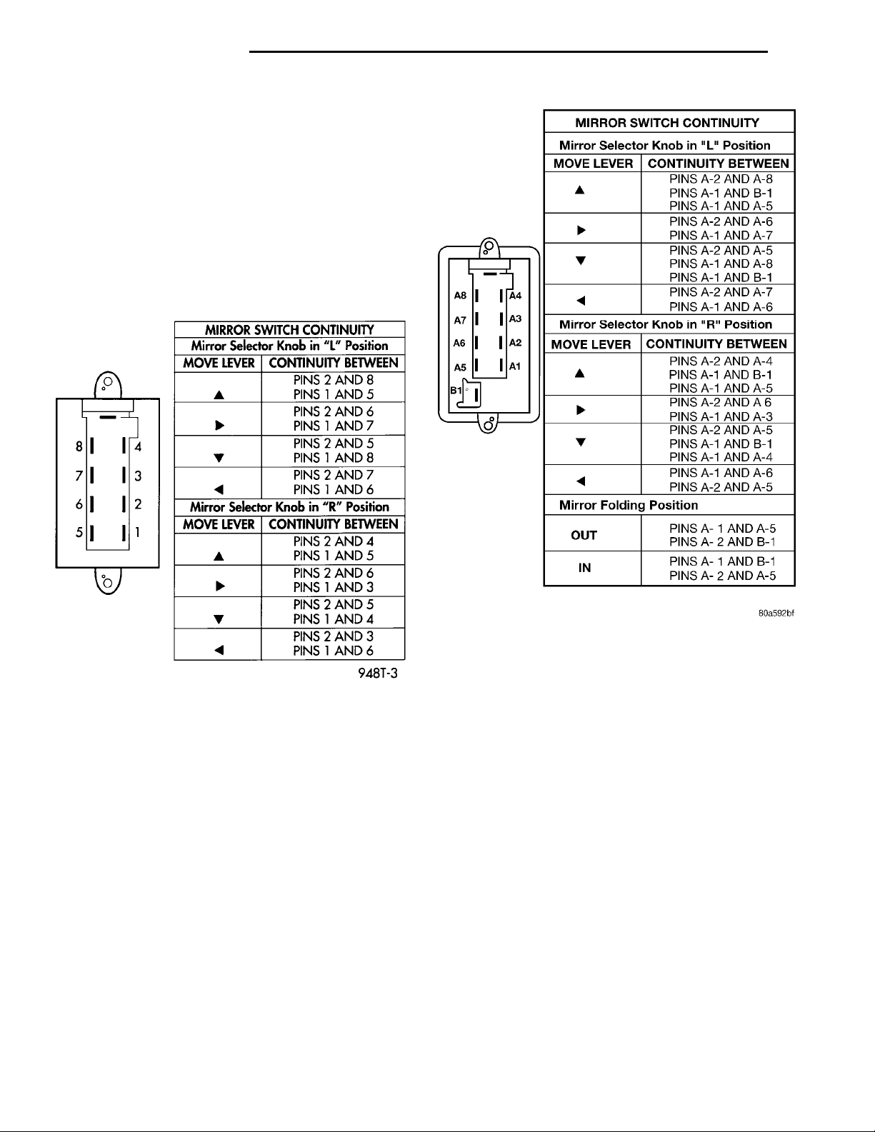
(3) Using an ohmmeter, test for continuity between
the terminals of the switch as shown in the Mirror
Switch Test (Fig. 3) and RHD Power Fold Away Mirror Switch Test (Fig. 4)
(4) If test results are not obtained as shown in the
(Fig. 3) or (Fig. 4), replace the switch.
Fig. 3 Mirror Switch Test
MIRROR MOTOR
(1) Remove door trim panel, refer to Group 23
Front Door Trim.
(2) Remove switch mounting screws from back side
of trim panel and remove switch.
Fig. 4 Power Fold Away Mirror Switch Test
Page 3
MIRROR SWITCH WIRINGCONNECTORSMIRROR RELAY CONNEC-TOR IN DOOR HARNESSMIRROR CONNECTOR INDOOR(S)TERMINAL ENDS VIEWS
PL POWER MIRRORS 8T - 3
DIAGNOSIS AND TESTING (Continued)
(3) Disconnect wire connector.
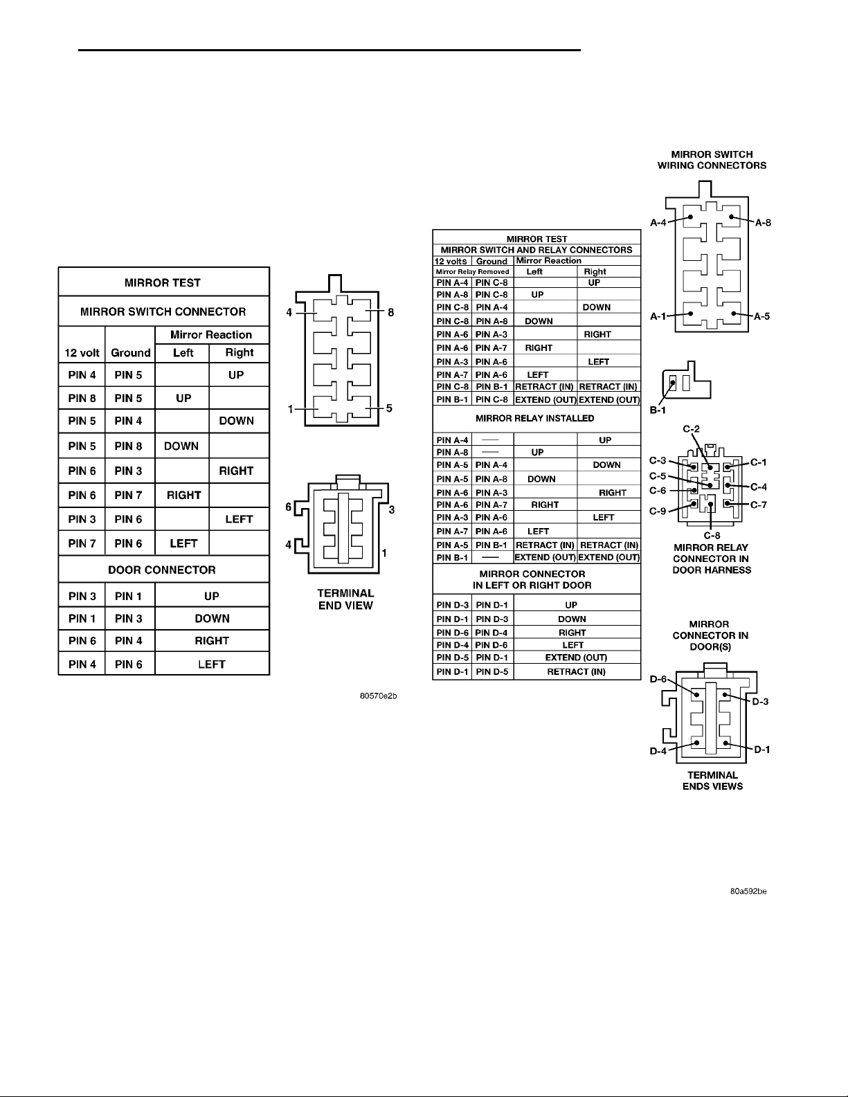
(4) Using two jumper wires, one connected to a 12
volt source, and 2 the other connected to a good body
ground. Refer to the Mirror Test (Fig. 5) for appropriate mirror response. RHD vehicle with Power Fold
Away Mirror refer to (Fig. 6)
(5) If test results are not obtained as shown in the
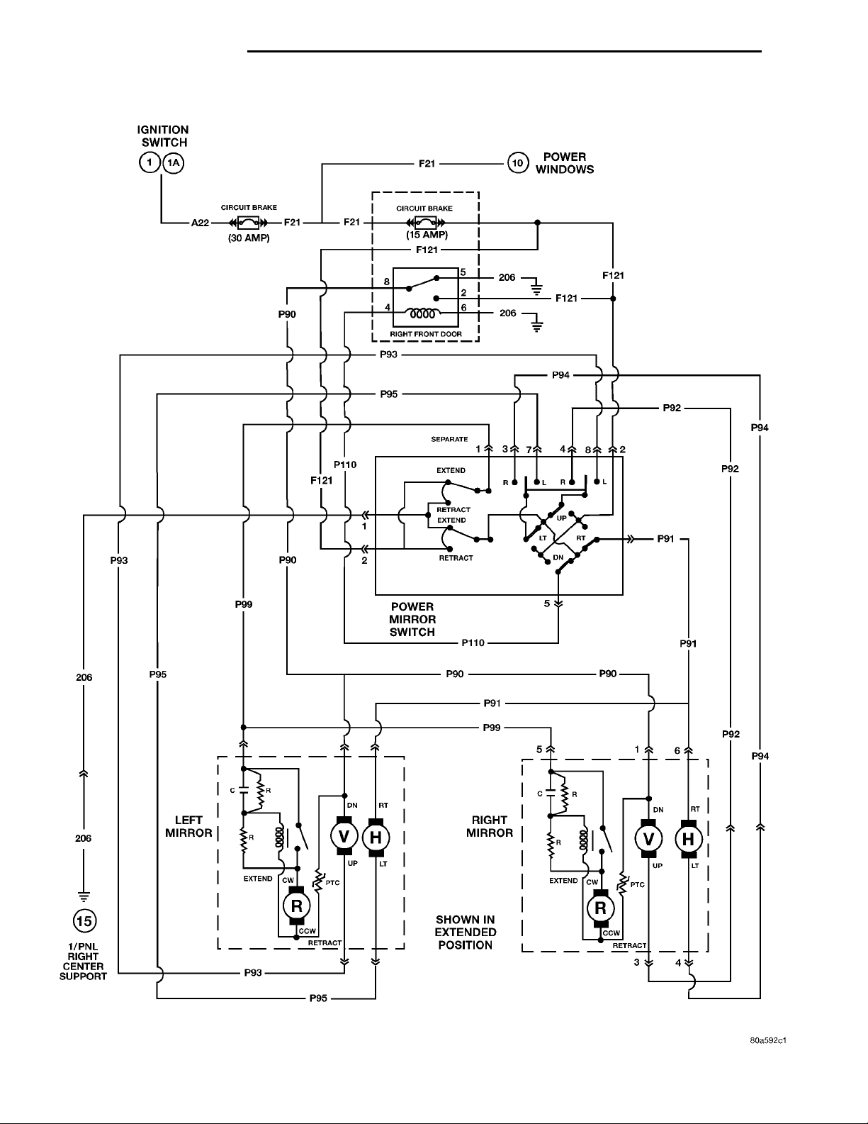
(Fig. 5), check for open or shorted circuit (Fig. 7), or
replace mirror assembly as necessary.
TERMINAL END VIEW
Fig. 5 Mirror Test
Fig. 6 Power Fold Away Mirror Test
Page 4
IGNITION SWITCHCIRCUIT BRAKE(30 AMP)CIRCUIT BRAKE(15 AMP)POWER WINDOWSRIGHT FRONT DOORSEPARATEEXTENDRETRACTRLRLUPRTDNLTRETRACTPOWER MIRROR SWITCHRIGHT MIRRORCRCWDNRTREXTENDPTCUPLTCCWRETRACTSHOWN IN EXTENDED POSI-TIONLTUPDNRTPTCCCWRETRACTCWEXTENDLEFT MIRRORCRR1/PNL RIGHT CENTER SUP-PORTEXTEND
8T - 4 POWER MIRRORS PL
Fig. 7 Power Fold Away Mirrors Wiring Schematic
Page 5
PL POWER MIRRORS 8T - 5
REMOVAL AND INSTALLATION
INSIDE MIRROR/READING LAMPS ASSEMBLY
REMOVAL
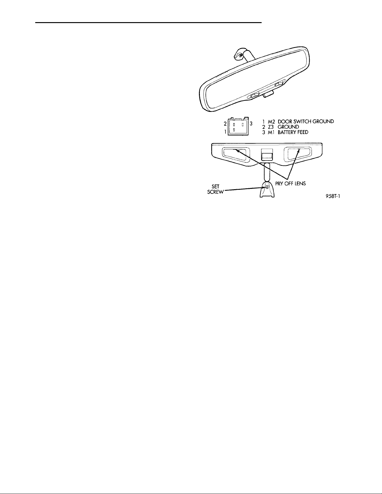
(1) Disconnect wiring connector.
(2) Loosen mirror set screw (Fig. 8).
(3) Lift mirror from mounting button.
INSTALLATION
For installation, reverse the above procedure.
Ensure the mirror is fully locked into place.
INSIDE MIRROR/READING LAMPS BULB/LENS
REMOVAL
(1) Using a small thin blade tool, pry at the center
of the lens nearest the mirror to remove lens (Fig. 8).
(2) Remove cartridge lamp and replace if necessary.
INSTALLATION
Install lens by setting lens into position and applying pressure until it is locked into position.
MIRROR SWITCH
INSTALLATION
For installation, reverse the above procedures.
Fig. 8 Mirror/Reading Lamps
REMOVAL
(1) Remove door trim panel, refer to Group 23
Front Door Trim.
(2) Remove switch mounting screws from back side
of trim panel and remove switch.
(3) Disconnect wire connector.
MIRROR ASSEMBLY
For door trim panel and mirror removal and installation, refer to Group 23 Body. Test operation of mirror before installing door trim panel.
Page 6

 Loading...