

Page 1
PL POWER WINDOWS 8S - 1
POWER WINDOWS
CONTENTS
page page
GENERAL INFORMATION
INTRODUCTION ........................ 1
DIAGNOSIS AND TESTING
WINDOW MOTOR TEST .................. 1
WINDOW SWITCH TEST .................. 1
GENERAL INFORMATION
INTRODUCTION
The window lift motors are of the permanent magnet type. A battery positive and negative connection
to either of the two motor terminals will cause the
motor to rotate in one direction. Reversing current
through these same two connections will cause the
motor to rotate in the opposite direction.
Each individual motor is grounded through the
master switch.
NOTE: This group covers both Left-Hand Drive
(LHD) and Right-Hand Drive (RHD) versions of this
model. Whenever required and feasible, the RHD
versions of affected vehicle components have been
constructed as mirror-image of the LHD versions.
While most of the illustrations used in this group
represent only the LHD version, the diagnostic and
service procedures outlined can generally be
applied to either version. Exceptions to this rule
have been clearly identified as LHD, RHD, or Export
if a special illustration or procedure is required.
DIAGNOSIS AND TESTING
WIRING TEST
The following wiring test determines whether or
not voltage is continuous through the body harness
to switch.
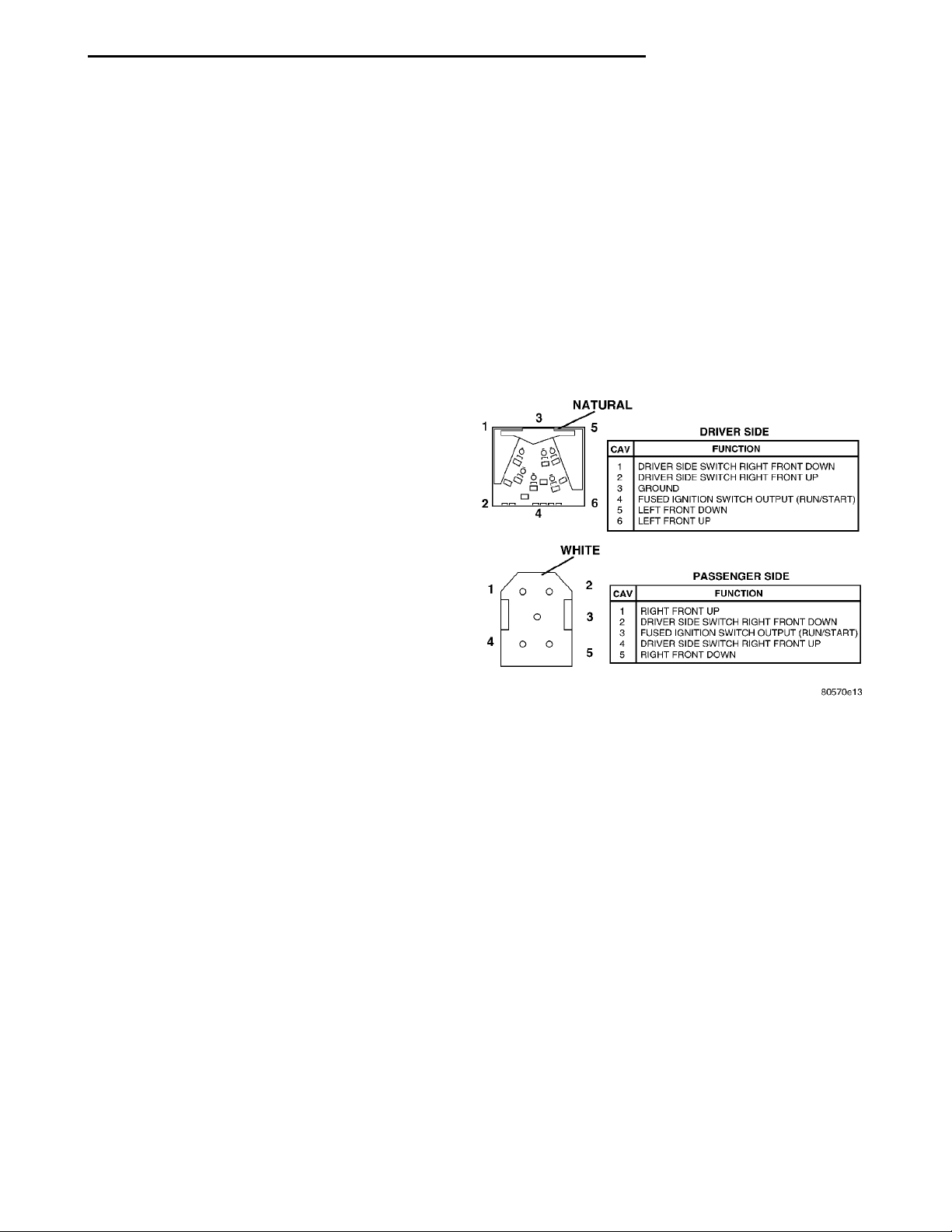
Remove switch for testing. Connect a voltmeter
positive lead to Pin 4 and negative lead to Pin 3 of
the switch connector (Fig. 1). Turn ignition switch to
the ON position. Voltmeter should read battery voltage. If OK, go to Window Switch Test. If not OK,
check the 30 amp circuit breaker behind the fuse
block or for a broken wire. For wiring, specific connector type and location, refer to Group 8W, Wiring
Diagrams.
WIRING TEST .......................... 1
REMOVAL AND INSTALLATION
2 DOOR WINDOW MOTOR ................ 2
4 DOOR WINDOW MOTOR ................ 4
WINDOW SWITCH ....................... 2
NATURALWHITE
Fig. 1 Window Switch Connectors
WINDOW SWITCH TEST
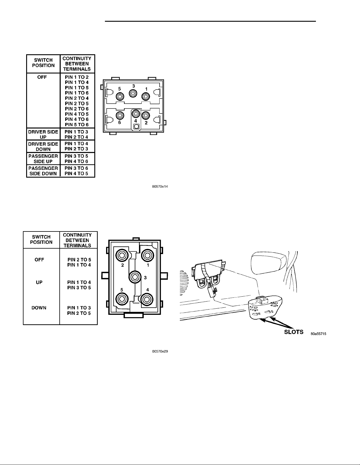
Remove the switch from its mounting, refer to the
Window Switch Removal and Installation procedures.. Using an ohmmeter, refer to the test procedures below, Driver Side or Passenger Side Window
Switch Continuity Test to determine if continuity is
correct (Fig. 2) and (Fig. 3). If the results are not
obtained, replace the switch.
WINDOW MOTOR TEST
(1) Remove door trim panel, refer to Group 23
Body for removal procedures.
(2) Connect positive (+) lead from a test battery to
either of the two motor terminals.
(3) Connect negative (-) lead from test battery to
remaining motor terminal.
(4) The motor should now rotate in one direction to
either move window up or down.
(a) If window happens to already be in full UP
position and motor is connected so as to move it in
UP direction no movement will be observed.
Page 2
8S - 2 POWER WINDOWS PL
DIAGNOSIS AND TESTING (Continued)
(5) If window moved completely up or down, the
test leads should be reversed one more time to complete a full window travel inspection.
(6) If window does not move, check to make sure
that it is free.
(7) It is necessary that the window be free to slide
up and down in the glass channels. If the window is
not free to move up and down, the window lift motor
will not be able to move the glass.
(8) To determine if the glass is free, disconnect the
regulator from the glass lift plate. Remove the two
attaching nuts, and slide the window up and down by
hand. This check can not be made on a four door
vehicle.
SLOTS
REMOVAL AND INSTALLATION
WINDOW SWITCH
REMOVAL
(1) Using a flat tool, insert tool in the slot on the
Fig. 2 Driver Side Window Switch Continuity Test
bottom of the switch bezel (Fig. 4).
(2) Pry the bezel from the door trim panel.
(3) Disconnect wire connector from switch.
(4) Remove switch by releasing the tabs from
bezel.
Fig. 3 Passenger Side Window Switch Continuity
Test
(b) Likewise, motor connected to move window
in DOWN direction no movement will be observed
if window is already in full DOWN position.
(c) Reverse battery leads in Step 2 and Step 3
and window should now move. If window does not
move, remove motor. See below for motor removal
from vehicle.
INSTALLATION
For installation, reverse above procedures.
Fig. 4 Switch Removal
2 DOOR WINDOW MOTOR
WARNING: DO NOT HAVE ANY HANDS OR FINGERS IN SECTOR GEAR AREA WHERE THEY CAN
BE PINCHED BY SMALL MOVEMENTS OF REGULATOR LINKAGE.
REMOVAL
(1) Move the window to the full-up position, if pos-
sible.
(2) Remove door trim panel and window regulator,
refer to Group 23 Body for removal procedures.
Page 3
MOTOR MOUNTINGSCREWS CLAMP REGULATOR TOSECTOR GEAR
PL POWER WINDOWS 8S - 3
REMOVAL AND INSTALLATION (Continued)
WARNING: FAILURE TO CLAMP THE SECTOR
GEAR TO THE MOUNTING PLATE WHEN REMOVING THE MOTOR CAN RESULT IN INJURY.
(3) Secure the sector gear and mounting plate with
a C clamp or similar clamping tool. This will prevent
a sudden and forceful movement of the regulator
when the motor is removed.
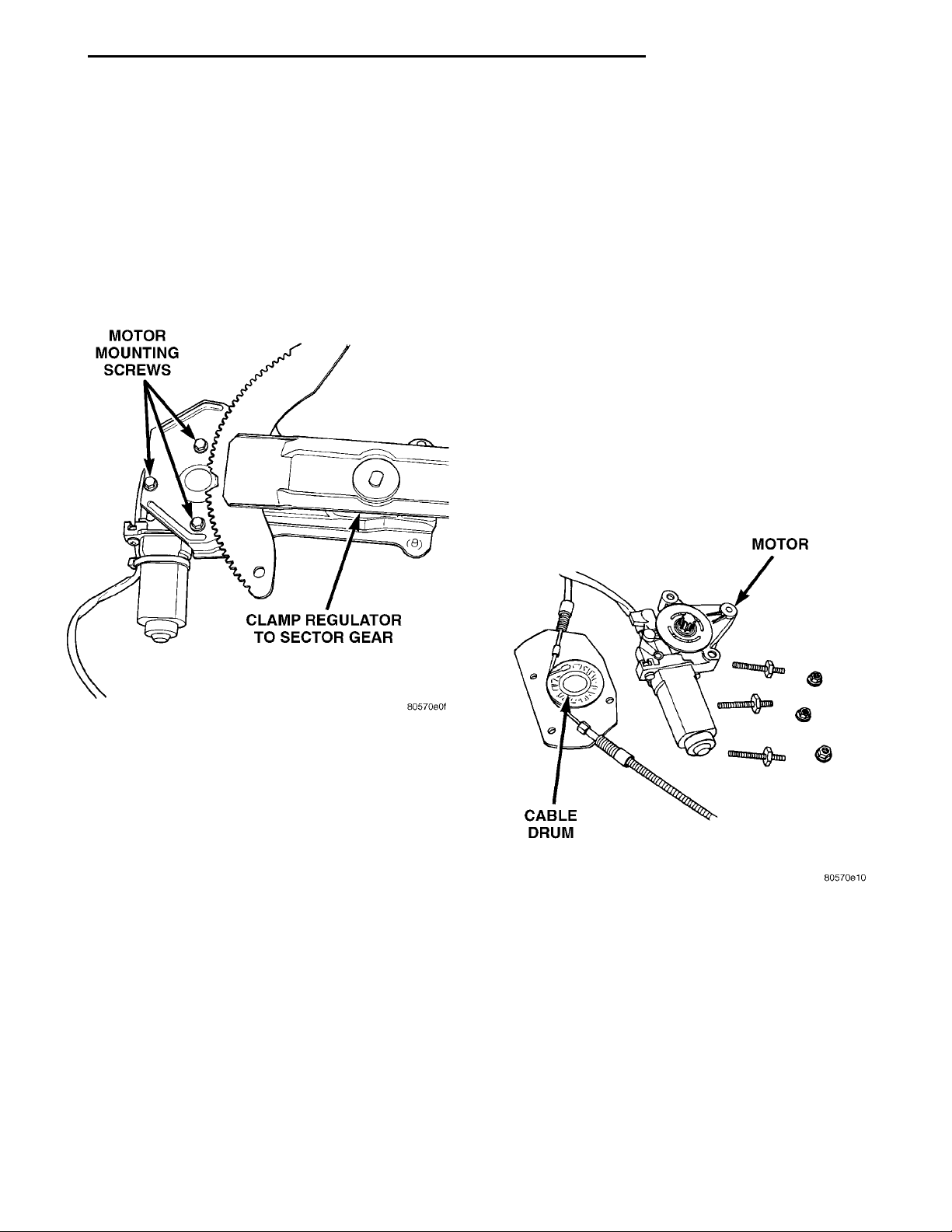
(4) Remove three mounting screws that hold motor
gearbox to regulator (Fig. 5).
(5) Remove motor from regulator.
4 DOOR WINDOW MOTOR
REMOVAL
(1) Move the window so it is not in the full up or
down position, if possible.
(2) Remove door trim panel, refer to Group 23
Body for removal procedures.
(3) Disconnect wiring connector from motor.
(4) Remove the three nuts attaching the window
regulator motor/housing to the door inner panel. This
will allow the motor/housing to be moved to the lower
door inner panel opening since the cables will flex
(Fig. 6).
(5) Turn the motor/housing to gain access to the
three nuts attaching the motor to the housing.
(6) Remove the three nuts attaching the motor to
the housing.
(7) Remove the motor from the housing. Be careful
not to pull the cable drum from the housing, as the
motor shaft will tend to pull the drum with it.
MOTORCABLE DRUM
Fig. 5 2 Door Motor Removal
INSTALLATION
(1) Install new motor on regulator by positioning
motor gearbox so that it engages regulator sector
teeth.
(2) A slight rotational or rocking movement may
be necessary to bring three motor gearbox screw
holes into proper position.
(3) Install three gearbox screws and one tie down
bracket screw, if applicable. Tighten to 5.6 to 8 N·m
(50 to 70 in. lbs.) torque.
(4) Install regulator, using the switch, test operation of motor.
Fig. 6 4 Door Motor Removal
INSTALLATION
For installation, reverse above procedures.
Page 4

 Loading...