

Page 1

PL POWER DOOR LOCKS 8P - 1
POWER DOOR LOCKS
CONTENTS
page page
POWER DOOR LOCKS .................... 1 REMOTE KEYLESS ENTRY ................. 3
POWER DOOR LOCKS
INDEX
page page
DESCRIPTION AND OPERATION
INTRODUCTION ........................ 1
DIAGNOSIS AND TESTING
DOOR LOCK MOTOR .................... 1
DOOR LOCK SWITCH .................... 1
DESCRIPTION AND OPERATION
INTRODUCTION
All doors can be locked or unlocked electrically by
operating the switch on either front door panels.
The rear doors can be locked or unlocked by actuation of the front door switch, or can be locked or
unlocked mechanically and independently with their
respective locking knobs.
The front doors can be locked or unlocked mechanically with the locking knob regardless of electrical
locking and unlocking actuation with the front door
knobs.
The right and left front door can be locked or
unlocked mechanically from the outside with the key
or electrically as described above.
CHILD PROTECTION LOCK
The child protection lock is on the rear door only.
The lock will disable the inside door handle from
opening the door when engaged. The lock is part of
the latch/lock assembly. The lock is engaged by moving a lever that is located on the rearward inside
edge of the door.
NOTE: This group covers both Left-Hand Drive
(LHD) and Right-Hand Drive (RHD) versions of this
model. Whenever required and feasible, the RHD
versions of affected vehicle components have been
constructed as mirror-image of the LHD versions.
While most of the illustrations used in this group
WIRING ............................... 2
REMOVAL AND INSTALLATION
DOOR LOCK MOTOR .................... 2
DOOR LOCK SWITCH .................... 2
represent only the LHD version, the diagnostic and
service procedures outlined can generally be
applied to either version. Exceptions to this rule
have been clearly identified as LHD, RHD, or Export
if a special illustration or procedure is required.
DIAGNOSIS AND TESTING
DOOR LOCK MOTOR
Make certain battery is in normal condition before
circuits are tested.
To determine which motor is faulty, check each
individual door for electrical lock and unlock or disconnect the motor connectors one at a time, while
operating the door lock switch. In the event that
none of the motors work, the problem maybe caused
by a shorted motor, or a bad switch. Disconnecting
the defective motor will allow the others to work.
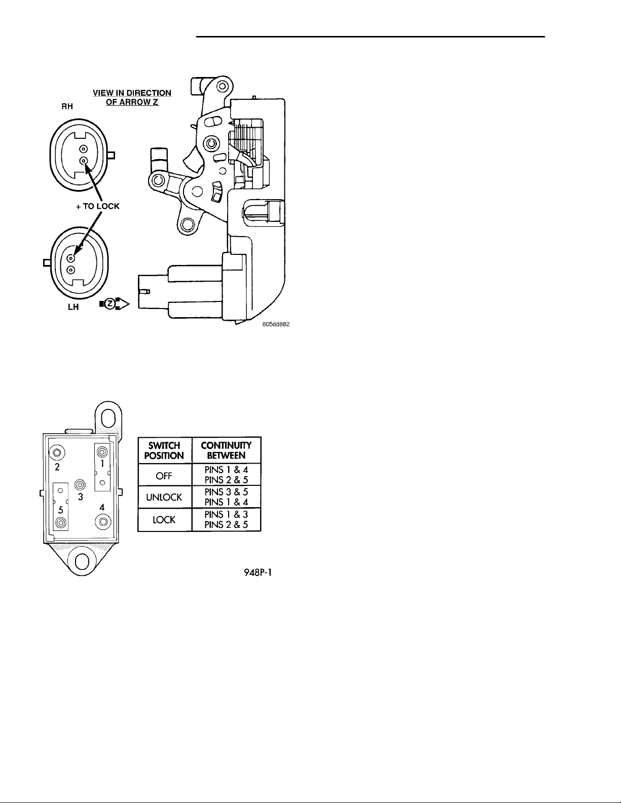
To test an individual door lock motor, disconnect
the electrical connector from the motor. To lock the
door, connect a 12 volt power source to the positive
pin of the lock motor and a ground wire to the other
pin (Fig. 1) To unlock the door reverse the wire connections at the motor pin terminals. If these results
are NOT obtained, replace the door latch assembly.
DOOR LOCK SWITCH
Remove the switch from its mounting location.
Using an ohmmeter, refer to (Fig. 2) to determine if
Page 2
VIEW IN DIRECTION OF
RH+ TO LOCKLH
ARROW Z
8P - 2 POWER DOOR LOCKS PL
DIAGNOSIS AND TESTING (Continued)
WIRING
The following wiring test sequence determines
whether or not voltage is continuous through the
body harness to switch.
(1) Remove left side switch from door trim panel.
(2) Carefully separate multiple terminal block on
wiring harness from switch body.
(3) Connect one lead of test light to a ground terminal. Touch other test light lead to Red Wire terminal.
(a) If test light comes on, the wiring circuit
between the battery and switch is functional.
(b) If test light does not come on, check fuse 3 in
the fuse block or for a open circuit.
(4) If test light comes on, the wiring circuit
between the battery and switch is functional.
REMOVAL AND INSTALLATION
Fig. 1 Door Latch Assembly
continuity is correct in the Lock and Unlock switch
positions. If these results are not obtained, replace
the switch.
Fig. 2 Door Lock Switch Continuity Test
DOOR LOCK MOTOR
REMOVAL
(1) Remove door trim panel, refer to Group 23,
Body for removal procedures.
(2) Disconnect all door linkages at the latch/lock
assembly (Fig. 1).
(3) Disconnect motor wire connector.
(4) Remove latch/lock assembly attaching screws
and remove assembly.
INSTALLATION
For installation, reverse the above procedures.
DOOR LOCK SWITCH
REMOVAL
(1) Remove front door trim, refer to Group 23,
Body for proper procedures.
(2) Disconnect wire connector.
(3) Remove attaching screws.
(4) Remove the switch.
INSTALLATION
For installation, reverse the above procedures.
Page 3
BATTERIES
PL POWER DOOR LOCKS 8P - 3
REMOTE KEYLESS ENTRY
INDEX
page page
GENERAL INFORMATION
INTRODUCTION ........................ 3
DESCRIPTION AND OPERATION
VEHICLE ACCESS CODE (VAC)
PROGRAMMING ....................... 3
DIAGNOSIS AND TESTING
REMOTE KEYLESS ENTRY CONDITION ...... 3
REMOTE KEYLESS ENTRY SYSTEM ........ 5
SERVICE PROCEDURES
HORN CHIRP CANCELLATION ............. 5
GENERAL INFORMATION
INTRODUCTION
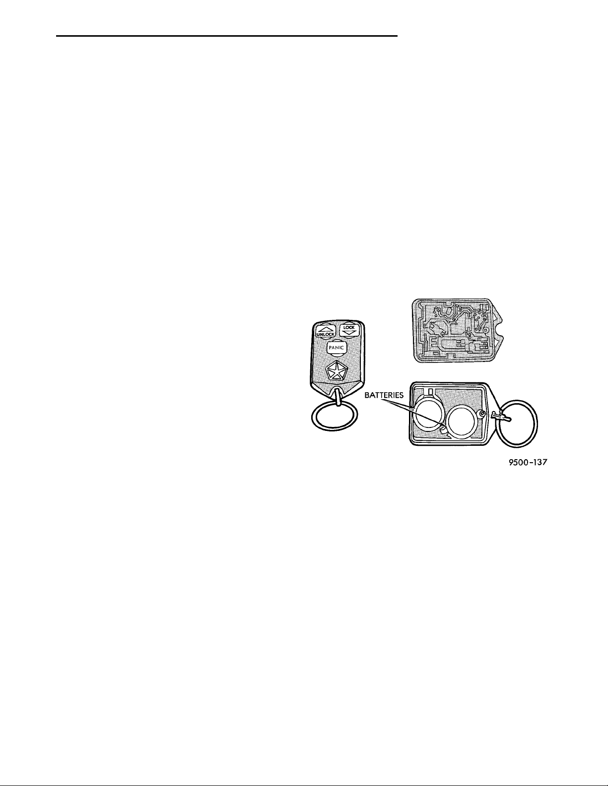
The key fob transmitter has three buttons to actuate and program the Remote Keyless Entry (RKE)
system (Fig. 1).
• UNLOCK: Actuating the UNLOCK button once
will unlock the driver door and activate the illuminated entry system. Actuating the UNLOCK button
twice within five seconds will unlock all doors.
• LOCK: Actuating the LOCK button locks all
doors and sounds horn (chirp). The chirp verifies the
door lock operation.
• PANIC: Actuating the PANIC button sounds the
horns and alternately flashes the headlamps and
parking lamps. The panic alarm will remain on for
one minute, until the PANIC button is actuated
again or the ignition is switched to the RUN position.
• The Remote Keyless Entry Module is capable of
retaining the transmitter Vehicle Access Code (VAC)
in memory even after vehicle power has been interrupted.
DESCRIPTION AND OPERATION
VEHICLE ACCESS CODE (VAC) PROGRAMMING
The system allows locking and unlocking of vehicle
door(s) by remote control using a hand held radio frequency transmitter. The ignition switch must be OFF
before the panic function can be activated with the
transmitter.
The receiver may receive VAC signals from two
transmitters. Each transmitter has its own Vehicle
Access Code and the code is programmed and stored
into receiver memory. If the transmitter is replaced
or a second transmitter is added, the codes of both
units have to be reprogrammed into the receiver
PANIC FUNCTION CANCELLATION .......... 5
PROGRAM REMOTE KEYLESS ENTRY
MODULE ............................ 5
REMOVAL AND INSTALLATION
REMOTE KEYLESS ENTRY MODULE ........ 6
SPECIFICATIONS
RKE TRANSMITTER BATTERY ............. 6
RKE TRANSMITTER RANGE ............... 6
Fig. 1 Key Fob Transmitter
memory. If a receiver module is replaced, both the
transmitter codes must be stored in the new receiver
memory.
OPERATION
The transmitter has three buttons for operation
(Fig. 1). They are LOCK, UNLOCK and PANIC.
The receiver is capable of retaining all Vehicle
Access Codes (VAC) even when power is removed.
Each remote keyless entry module (RKE) must
have at least one and no more than two transmitters.
DIAGNOSIS AND TESTING
REMOTE KEYLESS ENTRY CONDITION
Use an analog voltmeter for the following test.
Page 4
BLACK GRAY
8P - 4 POWER DOOR LOCKS PL
DIAGNOSIS AND TESTING (Continued)
REMOTE KEYLESS ENTRY GENERAL CHECKS BEFORE OTHER CHECKS.
(1) Check if door locks operate properly. If not OK,
repair as necessary.
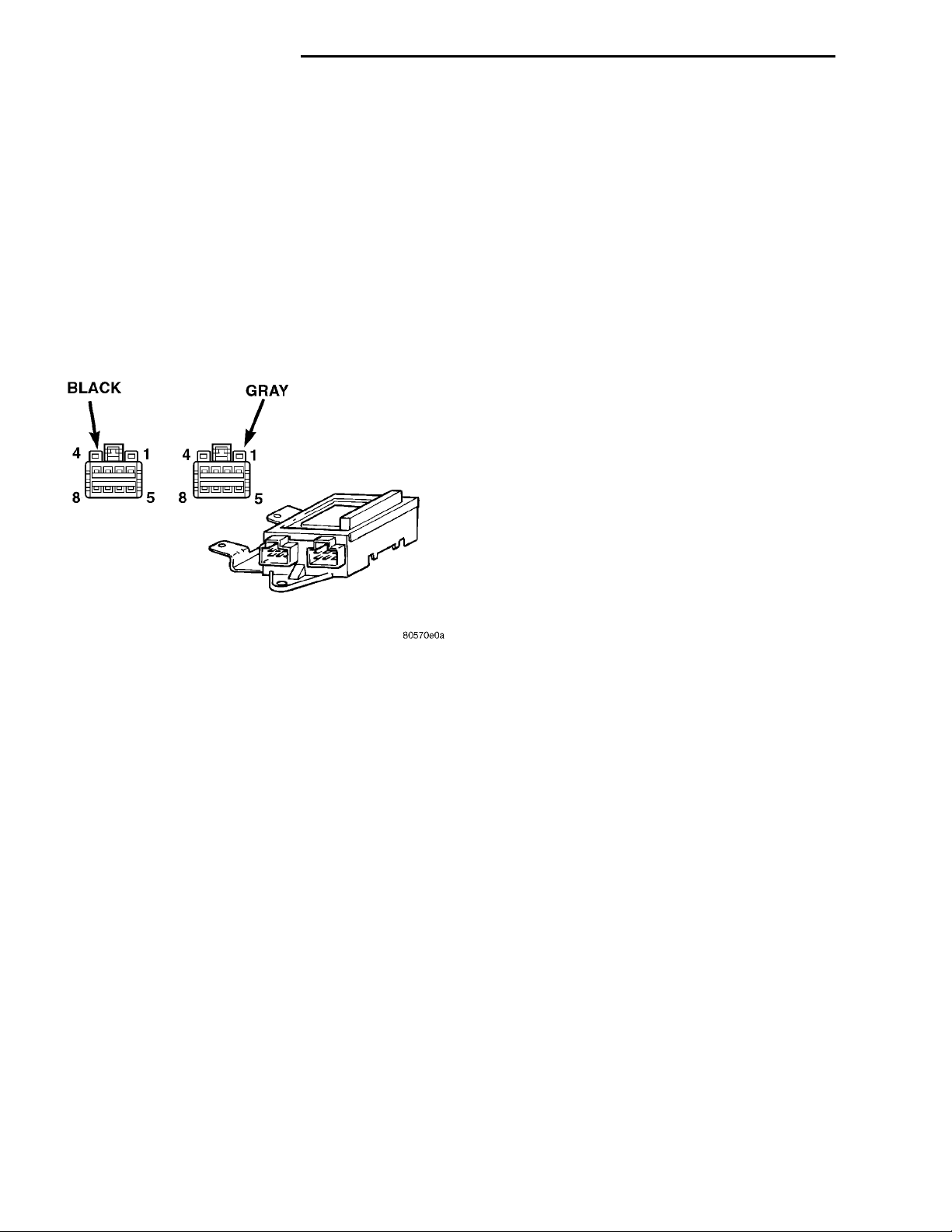
(2) Disconnect the wire connectors at the RKE
module Using a ohmmeter check for continuity
between the Pins of the wire connectors (Fig. 2):
• Pin 1 to Pin 4 of the gray connector.
• Pin 2 to Pin 3 of the gray connector.
• Pin 1 of the black connector to Pin 3 of the gray
connector.
If no continuity repair as necessary. Refer to Group
8W, Wiring Diagrams.
the unlock button once and check for a voltage pulse
(Fig. 2).
(2) If no voltage pulse is measured, replace the
receiver. If voltage pulse is measured, check the wiring to the driver door and repair as necessary.
DRIVER DOOR WILL UNLOCK WITH THE TRANSMITTER, BUT ALL OTHER DOORS WILL NOT UNLOCK
(1) Using an analog voltmeter, connect the meter
to Pin 3 of the gray connector and to ground (Fig. 2).
Press the unlock button twice within five seconds
and check for a voltage pulse.
(2) If no voltage pulse is measured, replace the
receiver. If voltage pulse is measured, check the wiring to the passenger door lock motors and repair as
necessary.
ALL DOORS WILL NOT LOCK WITH THE TRANSMITTER
(1) Using an analog voltmeter, connect the meter
to Pin 1 of the gray connector and to ground. Press
the lock button and check for a voltage pulse (Fig. 2).
(2) If no voltage pulse is measured, replace the
receiver. If voltage pulse is measured, check the wiring to the door lock motors and repair as necessary.
Fig. 2 Remote Keyless Entry Module
(3) Using a voltmeter, check the wire connectors
for battery feed and ignition feed (Fig. 2):
• Check Pin 2 of the black connector for battery
feed.
• Check Pin 8 of the black connector for ignition
feed with the ignition key in the ON position.
If not OK, check and repair as necessary.
(4) Using a ohmmeter, check the Pin 8 of the black
connector for continuity to ground. If not OK, check
and repair as necessary (Fig. 2).
(5) Test transmitter batteries for at least six volts.
If not OK, replace batteries as necessary.
(6) Check if module is programmed properly. Refer
to Program Remote Keyless Entry Module. If module
will not program check for continuity between Pin 4
of the black connector to the programming line connector (Fig. 2). If no continuity repair as necessary,
refer to Group 8W, Wiring Diagrams.
(7) Check if horn operates properly. If not OK,
repair as necessary.
DRIVER DOOR WILL NOT UNLOCK WITH THE TRANSMITTER
(1) Using an analog voltmeter, connect the meter
to Pin 1 of the black connector and to ground. Press
DOORS WILL LOCK USING THE TRANSMITTER BUT THERE IS NO HORN CHIRP
(1) Using an analog voltmeter, connect the meter
to Pin 6 of the gray connector and to ground. Press
the lock button and check for a voltage pulse
decrease (Fig. 2).
(2) If no voltage pulse decrease is measured,
replace the receiver. If voltage OK, repair circuit to
the horn relay as necessary.
ILLUMINATED ENTRY FAILS TO WORK IN INITIAL UNLOCKING WITH TRANSMITTER
(1) Using an analog voltmeter, connect the meter
to Pin 6 of the black connector and to ground. Press
the lock button and check for a voltage pulse
decrease (Fig. 2).
(2) If no voltage pulse decrease is measured,
replace the receiver. If voltage OK, repair circuit to
the dome as necessary.
PARKING LAMPS AND/OR HEAD LAMPS FAIL TO FLASH WITH PANIC BUTTON
(1) Using an analog voltmeter, connect the meter
to Pin 5 of the gray connector and to ground to test
parking lamps out put. Press the panic button and
check for a voltage pulse (Fig. 2).
(2) If no voltage pulse is measured, replace the
receiver. If voltage OK, repair circuit to the parking
lamps as necessary.
Page 5

PL POWER DOOR LOCKS 8P - 5
DIAGNOSIS AND TESTING (Continued)
(3) Connect the meter to Pin 5 of the black connector and to ground to test head lamps out put. Press
the panic button and check for a voltage pulse (Fig.
2).
(4) If no voltage pulse is measured, replace the
receiver. If voltage OK, repair circuit to the head
lamps as necessary.
REMOTE KEYLESS ENTRY SYSTEM
When trouble shooting problems with the Remote
Keyless Entry System, always verify that the power
door lock/unlock switches are functional. If the doors
do not lock/unlock refer to Group 8W, Wiring Diagram for Pin and wiring locations.
If the following items do not work:
• Remote keyless entry system
• Radio/clock
• Door lock switches
A blown fuse is the probable cause. Check fuses 2,
3 and 11 in the fuse block. To check for a blown fuse,
pull the fuse out slightly, but maintain contact
between the fuse terminals and the terminals in fuse
block. Using the voltmeter probe, check both terminals for 12 volts. If only one terminal measures battery voltage, the circuit breaker is defective and must
be replaced. If neither terminal measures battery
voltage, check the high current fuses 3 and 11 in the
Power Distribution Center (PDC). The PDC is located
in the engine compartment. If fuse(s) are NOT OK,
replace fuse(s) or repair as necessary. If fuses are
OK, check for an open or shorted circuit to the Power
Distribution Center, repair as needed.
(6) Disconnect the programming line from ground.
This returns the system to its normal operation
mode.
(7) Replace any removed components. Return programming line chirpto its original position. Check for
system operation.
PANIC FUNCTION CANCELLATION
During the programming operation the panic function can be disabled or enable using the following
procedure. One or both transmitters can be program
to be disabled or enable.
(1) Retrieve the programming line from the upper
edge of the passenger side cowl trim panel. The RKE
Program Line is a green wire with a red bullet connector.
(2) Using a jumper wire, ground the RKE Programming Line.
(3) Turn ignition switch to the ON position.
(4) Press any button on the transmitter. The locks
will cycle to confirm programming,
(5) To disable or enable panic function press the
panic button on the transmitter four times and the
horn will sound to confirm programming. Press the
panic button on the second transmitter four times
and the horn will sound to confirm programming.
(6) Disconnect the programming line from ground.
This returns the system to its normal operation
mode.
(7) Replace any removed components. Return the
programming line to its original position. Check for
system operation.
SERVICE PROCEDURES
HORN CHIRP CANCELLATION
During the programming operation the horn chirp
can be disabled or enable using the following procedure. One or both transmitters can be program to be
disabled or enable.
(1) Retrieve the programming line from the upper
edge of the passenger side cowl trim panel upper
edge. The RKE Programming Line is a green wire
with a red bullet connector.
(2) Using a jumper wire, ground the RKE programming line.
(3) Turn ignition switch to the ON position.
(4) Press any button on the transmitter. The locks
will cycle to confirm programming,
(5) To disable or enable horn chirp press the lock
button on the transmitter four times and the horn
will sound to confirm programming. Press the lock
button on the second transmitter four times and the
horn will sound to confirm programming.
PROGRAM REMOTE KEYLESS ENTRY MODULE
(1) Retrieve the programming line from the upper
edge of the passenger side cowl trim panel. The RKE
Programming Line is a green wire with a red bullet
connector.
(2) Using a jumper wire, ground the RKE programming line.
(3) Turn ignition switch to the ON position.
(4) Press any button on the transmitter to set
code. The locks will cycle to confirm programming. If
there is a second transmitter it must be set at this
time. Press any button on the second transmitter and
wait for the locks to cycle to confirm programming.
(5) Disconnect the programming line from ground.
This returns the system to its normal operation
mode.
(6) Replace all removed components. Return programming line to its original position. Check for system operation.
Page 6
8P - 6 POWER DOOR LOCKS PL
REMOVAL AND INSTALLATION
REMOTE KEYLESS ENTRY MODULE
REMOVAL
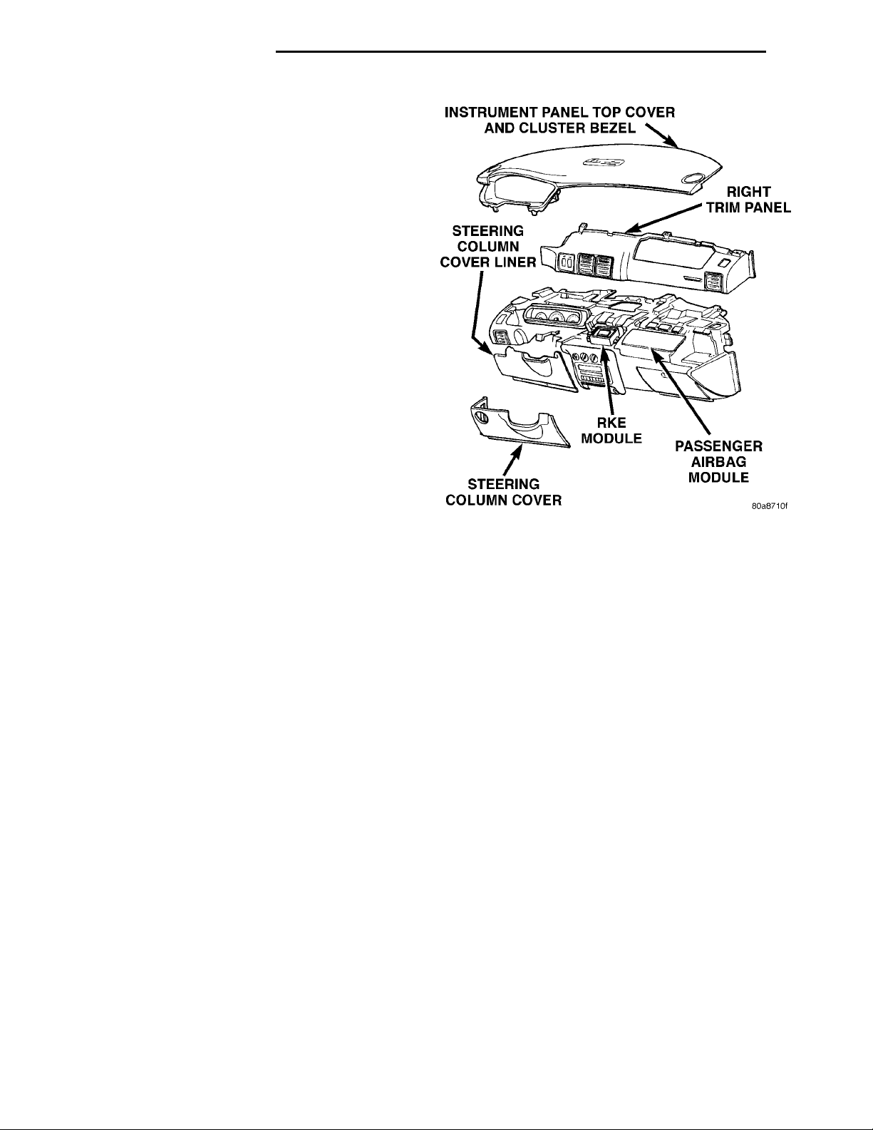
(1) Remove the right trim panel, refer to Group
8E, Instrument Panel and Systems for proper
removal procedures.
(2) Disconnect wire connector from RKE module.
(3) Remove screws holding RKE module to instrument panel assembly (Fig. 3).
(4) Remove module.
INSTALLATION
For installation, reverse above procedures.
SPECIFICATIONS
RKE TRANSMITTER BATTERY
The batteries can be removed without special tools
and are readily available at local retail stores. The
recommended battery is Duracell DL 2016 or equivalent. Battery life is about one to two years.
CAUTION: Do not touch the battery terminals or
handle the batteries any more than necessary.
Hands must be clean and dry.
RKE TRANSMITTER RANGE
Normal operation range is up to about a distance
of 7 meters (23 ft.) of the vehicle. Range may be better or worse depending on the environment around
Fig. 3 RKE Module Location
the vehicle. Closeness to a radio frequency transmitter such as a radio station tower may degrade operational range, while range in an open field will be
enhanced.
 Loading...