

Page 1
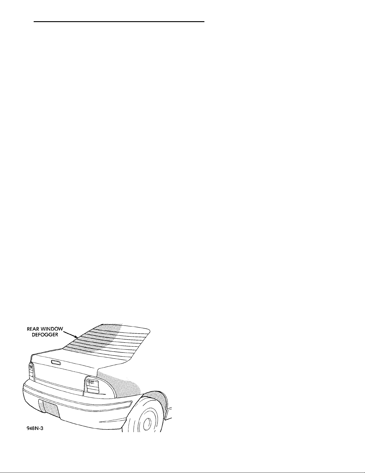
REAR WINDOW DEFOGGER
PL ELECTRICALLY HEATED SYSTEMS 8N - 1
ELECTRICALLY HEATED SYSTEMS
CONTENTS
page page
DESCRIPTION AND OPERATION
INTRODUCTION ........................ 1
REAR WINDOW DEFOGGER SWITCH ....... 1
DIAGNOSIS AND TESTING
DEFOGGER SYSTEM .................... 1
DESCRIPTION AND OPERATION
INTRODUCTION
For proper operation of the Rear Window Defogger
system refer to the Owner’s Manual.
The system consists of a rear glass with two vertical bus bars and a series of electrically connected
grid lines fired on the inside surface. A control switch
and a timer relay combined into a single assembly is
used on all models (Fig. 1).
Circuit protection is provided by a maxi fuse,
located in the Power Distribution Center, for the
heated grid circuit and by a fuse for the relay control
circuit.
When the switch is turned to the ON position, current is directed to the rear defogger grid lines. The
heated grid lines heat the rear glass to clear the surface of fog or frost.
CAUTION: Grid lines can be damaged or scraped
off with sharp instruments, care should be taken in
cleaning glass or removing foreign materials,
decals or stickers. Normal glass cleaning solvents
or hot water used with rags or toweling is recommended.
GRID LINES ............................ 2
REAR WINDOW DEFOGGER SWITCH ....... 3
SERVICE PROCEDURES
GRID LINE AND TERMINAL REPAIR ......... 3
NOTE: This group covers both Left-Hand Drive
(LHD) and Right-Hand Drive (RHD) versions of this
model. Whenever required and feasible, the RHD
versions of affected vehicle components have been
constructed as mirror-image of the LHD versions.
While most of the illustrations used in this group
represent only the LHD version, the diagnostic and
service procedures outlined can generally be
applied to either version. Exceptions to this rule
have been clearly identified as LHD, RHD, or Export
if a special illustration or procedure is required.
REAR WINDOW DEFOGGER SWITCH
The rear window defogger switch is a control
switch and timer relay integrated into a single panel
mounted assembly. Actuating the switch energizes
the circuit which allows current to flow through the
grid lines. Upon initial actuation for approximately
eight to ten minutes, or until either the switch or
ignition is turned off. An indicating lamp illuminates
a lens inlaid in the control switch.
DIAGNOSIS AND TESTING
Fig. 1 Rear Window Defogger
DEFOGGER SYSTEM
Electrically heated rear window defogger operation
can be checked in vehicle in the following manner:
(1) Turn ignition switch to the ON position.
(2) Connect an ammeter in series with the battery.
Push the defogger control switch to the ON position.
A distinct increase in amperage draw should be
noted.
(3) The rear window defogger operation can be
checked by feeling the glass. A distinct difference in
temperature between the grid lines and adjacent
clear glass can be detected in three to four minutes
of operation.
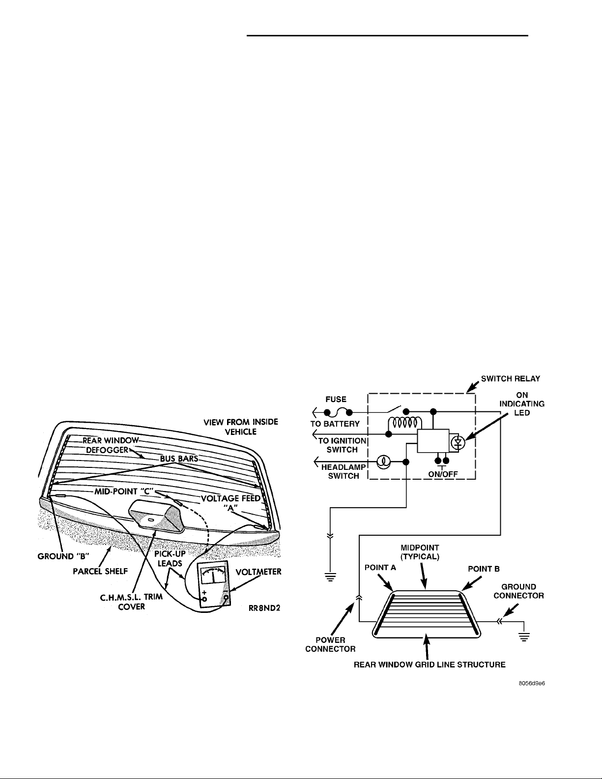
(4) Using a DC voltmeter, connect negative lead to
Point B, and the positive lead to Point A (Fig. 2). The
voltmeter should read 10-14 volts.
Page 2
REAR WINDOWDEFOGGER
C.H.M.S.L. TRIM COVERPARCEL SHELFGROUND “B’’MID-POINT “C’’
PICK-UPLEADS
VIEW FROM INSIDE VEHI-CLEVOLTAGE FEED “A’’VOLTMETER
BUS BARS
FUSE SWITCH RELAYON INDICATINGLEDON/OFFMIDPOINT (TYPI-CAL) POINT BGROUND CON-NECTORREAR WINDOW GRID LINESTRUCTUREPOWER CONNEC-TORPOINT AHEADLAMP SWITCHTO IGNITION SWITCHTO BATTERY
8N - 2 ELECTRICALLY HEATED SYSTEMS PL
DIAGNOSIS AND TESTING (Continued)
(5) Step 2, Step 3 or Step 4 above will confirm
system operation. Indicator light illumination means
that there is power available at the output of the
relay only, and does not necessarily verify system
operation.
(6) If turning the switch ON produced no distinct
current draw on the ammeter the problem should be
isolated in the following manner:
(a) Confirm the ignition switch is ON.
(b) Ensure that the heated rear glass feed wire
is connected to the terminal or pigtail and that the
ground wire is in fact grounded.
(c) Ensure that the maxi-fuse and control circuit
fuse are OK and all electrical connections are
secure.
(7) When the above steps have been completed and
the system is still inoperative, one or more of the following is defective:
(a) Control switch/timer relay module.
(b) All rear window grid lines would have to be
broken or one of the feed wires are not connected
for the system to be inoperative.
(8) If turning the switch ON produces severe volt-
meter deflection, the circuit should be closely checked
for a shorting condition.
(9) If the system operation has been verified but
indicator lamp does not light, replace the switch.
(10) For detailed wiring information, refer to group
8W, Wiring Diagrams.
occur in an individual grid line resulting in no current flow through the line. To detect breaks in grid
lines the following procedure is required:
(1) Turn ignition ON and turn control switch to
ON. The indicator light should come on.
(2) Using a DC voltmeter with 0-15 volt range,
contact terminal B with negative lead of voltmeter.
With positive lead of voltmeter, contact terminal A
(Fig. 2). The voltmeter should read 10-14 volts. A
lower voltage reading indicates a poor connection in
the feed or the ground circuit.
(3) With negative lead of voltmeter, contact a good
body ground point. The voltage reading should not
change.
(4) Connect negative lead of voltmeter to terminal
B and touch each grid line at Mid-Point with Positive
lead. A reading of:
• Approximately 6 volts indicates the line is OK
• 0 volts indicates a break in line between Mid-
Point C and terminal A
• 10-14 volts indicates a break between Mid-Point
C and terminal B
Move the lead toward the break and voltage will
change as soon as break is crossed. Refer to (Fig. 2)
and (Fig. 3).
Fig. 2 Rear Glass Grid Line Test
GRID LINES
The horizontal grid lines and vertical bus bar lines
printed and fired on inside surface of rear window
glass (Fig. 2) comprise an electrical parallel circuit.
The electrically conductive lines are composed of a
silver-ceramic material which when fired on glass
becomes bonded to the glass and is highly resistant
to abrasion. It is possible, however, that a break may
Fig. 3 Systems Electrical Circuit
Page 3
“ON” INDICATOR LED 1 - SYMBOL LAMP2 - GROUND3 - IGNITION4 - BATTERY5 - TO BACK GLASSBEZEL
REAR FOG LAMP SWITCH1 - SYMBOL LAMP2 - GROUND3 - IGNITION4 - BATTERY5 - TO BACK GLASSBEZELREAR WINDOW DEFOGGERSWITCH“ON” INDICATOR LED
PL ELECTRICALLY HEATED SYSTEMS 8N - 3
DIAGNOSIS AND TESTING (Continued)
REAR WINDOW DEFOGGER SWITCH
The rear window defogger switch may be tested invehicle or bench tested. In vehicle testing is accomplished in the following manner:
(1) Remove the switch from the instrument panel
but leave the switch connected, refer to Group 8E,
Instrument Panel and Systems for removal procedures.
(2) Turn the ignition switch ON.
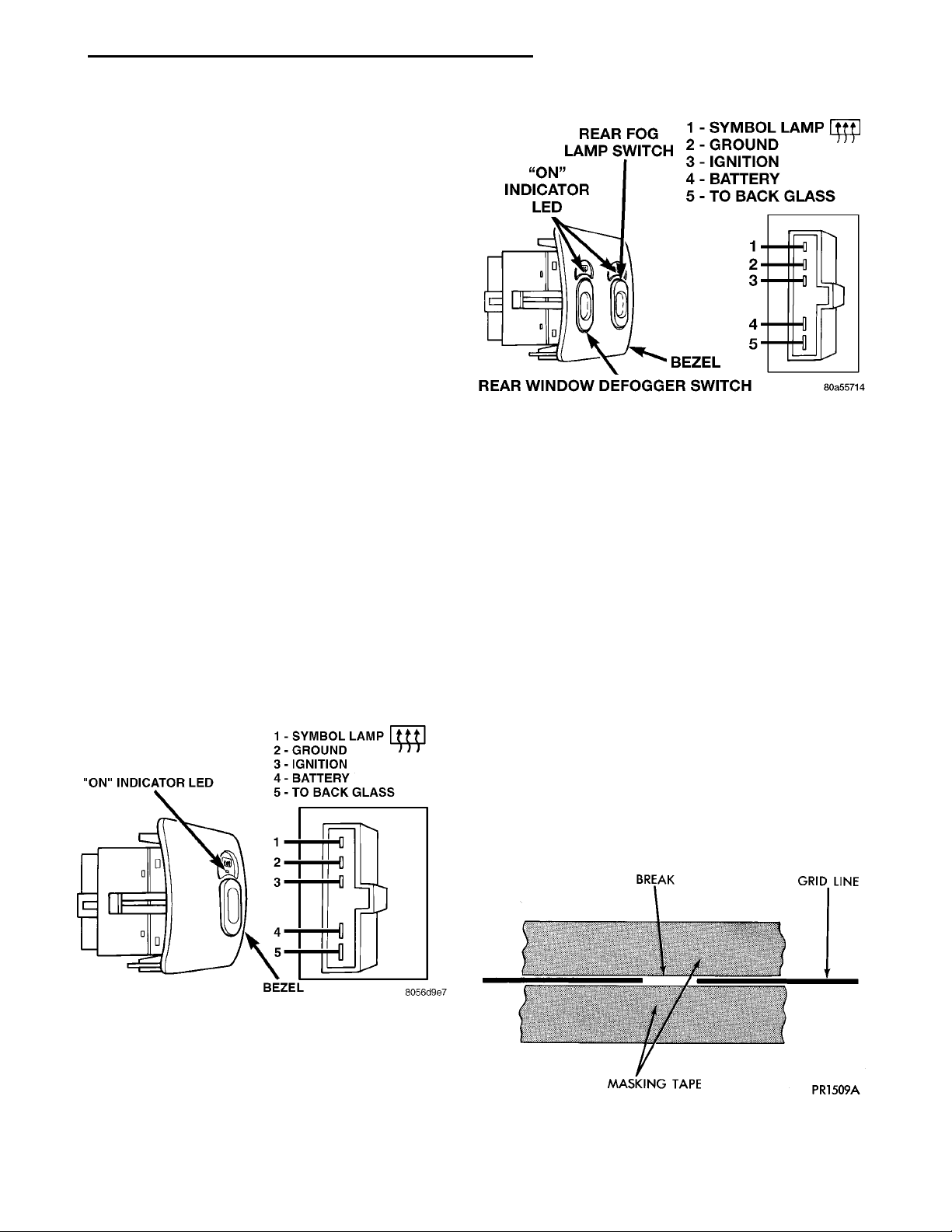
(3) Using a voltmeter, check for battery voltage at
Pin 3 and Pin 4 (Fig. 3), (Fig. 4) and (Fig. 5).
(a) If OK, go to Step 4.
(b) If NOT OK, check fuse 8 in fuse block and
the 30 Amp maxi fuse in the Power Distribution
Center (PDC). If fuses are OK, check wiring circuit. Refer to Group 8W, Wiring Diagrams.
(4) Check Pin 5, with switch in the ON position
there should be battery voltage and no voltage in the
OFF position.
(a) If OK, go to Step 5.
(b) If NOT OK, no voltage in the ON position or
voltage in the OFF position. Replace the switch/relay module.
(5) Press switch to ON position. The indicator
lamp should come on and remain on for approximately 10 minutes. If the indicator lamp fails to light
or no voltage is present for approximately 10 minutes. Replace Rear Window Defogger Switch.
(6) To bench test relay:
(a) Using a jumper wire connect a 12 volt batter
supply, apply voltage to Pin 3 and 4. Ground Pin 2.
(b) Follow the above procedures except Step 2
BREAK GRID LINEMASKING TAPE
Fig. 5 Rear Window Defogger Switch - Export
SERVICE PROCEDURES
GRID LINE AND TERMINAL REPAIR
WARNING: REPAIR KIT MAY CAUSE SKIN OR EYE
IRRITATION. CONTAINS EPOXY RESIN AND AMINE
TYPE HARDENER, HARMFUL IF SWALLOWED.
AVOID CONTACT WITH SKIN AND EYES. FOR SKIN,
WASH AFFECTED AREAS WITH SOAP AND WATER.
DO NOT TAKE INTERNALLY. IF TAKEN INTERNALLY, INDUCE VOMITING; CALL A PHYSICIAN
IMMEDIATELY. IF IN CONTACT WITH EYES, FLUSH
WITH PLENTY OF WATER. USE WITH ADEQUATE
VENTILATION. DO NOT USE NEAR FIRE OR FLAME.
CONTENTS CONTAIN 3 PERCENT FLAMMABLE
SOLVENTS.
KEEP OUT OF REACH OF CHILDREN.
Fig. 4 Rear Window Defogger Switch
The repair of the grid lines or the terminal is possible using the Mopar t Repair Package or equivalent.
(1) Mask repair area so conductive epoxy can be
extended onto the line or the bus bar (Fig. 6).
Fig. 6 Grid Line Repair
Page 4

8N - 4 ELECTRICALLY HEATED SYSTEMS PL
SERVICE PROCEDURES (Continued)
(2) Follow instructions in repair kit for preparing
damaged area.
(3) Remove package separator clamp and mix plastic conductive epoxy thoroughly. Fold in half and cut
center corner to dispense epoxy.
(4) For grid line, mark off area to be repaired with
masking tape or a template (Fig. 6).
(5) Apply conductive epoxy through slit in masking
tape. Overlap both ends of the break by 19 mm (3/4
inch).
(6) For a terminal or pigtail replacement, mask
adjacent areas so epoxy can be extended onto line as
well as bus bar. Apply a thin layer of epoxy to area
where terminal was fastened and to adjacent line.
(7) Apply a thin layer of conductive epoxy on terminal and place terminal on desired location. To pre-
vent terminal from moving while the epoxy is curing,
it must be wedged or clamped.
(8) Carefully remove masking tape from grid line.
CAUTION: Do not allow the glass surface to
exceed 204°C (400°F), glass may fracture.
(9) Allow epoxy to cure 24 hours at room temperature or use heat gun with a 260°to 371°C (500° to
700°F) range for 15 minutes. Hold gun approximately
254 mm (10 inches) from repaired area.
(10) After conductive epoxy is properly cured
remove wedge from terminal and check out operation
of rear window defogger. Do not attach connectors
until curing is complete.
 Loading...