

Page 1

PL RESTRAINT SYSTEM 8M - 1
RESTRAINT SYSTEM
CONTENTS
page page
GENERAL INFORMATION
WARNINGS AND PRECAUTIONS ........... 1
DESCRIPTION AND OPERATION
AIRBAG CONTROL MODULE .............. 2
CLOCKSPRING ......................... 2
DRIVER AND PASSENGER AIRBAG MODULE . . 2
DIAGNOSIS AND TESTING
AIRBAG SYSTEM TEST ................... 3
SERVICE PROCEDURES
CLEANUP PROCEDURE .................. 3
GENERAL INFORMATION
WARNINGS AND PRECAUTIONS
WARNING: THIS SYSTEM IS A SENSITIVE, COMPLEX ELECTRO–MECHANICAL UNIT. DISCONNECT
AND ISOLATE THE BATTERY NEGATIVE CABLE
BEFORE BEGINNING AIRBAG SYSTEM COMPONENT REMOVAL OR INSTALLATION PROCEDURES.
THIS WILL DISABLE THE AIRBAG SYSTEM. FAILURE TO DISCONNECT THE BATTERY COULD
RESULT IN ACCIDENTAL AIRBAG DEPLOYMENT
AND POSSIBLE PERSONAL INJURY.
ALLOW SYSTEM CAPACITOR TO DISCHARGE
FOR TWO MINUTES BEFORE REMOVING AIRBAG
COMPONENTS.
DO NOT PLACE AN INTACT UNDEPLOYED AIRBAG FACE DOWN ON A SOLID SURFACE, THE AIRBAG WILL PROPEL INTO THE AIR IF
ACCIDENTALLY DEPLOYED AND COULD RESULT
IN PERSONAL INJURY. WHEN CARRYING OR HANDLING AN UNDEPLOYED AIRBAG MODULE, THE
TRIM SIDE OF THE AIRBAG SHOULD BE POINTING
AWAY FROM THE BODY TO MINIMIZE POSSIBILITY
OF INJURY IF ACCIDENTAL DEPLOYMENT
OCCURS.
REPLACE AIRBAG SYSTEM COMPONENTS WITH
MOPART REPLACEMENT PARTS. SUBSTITUTE
PARTS MAY APPEAR INTERCHANGEABLE, BUT
INTERNAL DIFFERENCES MAY RESULT IN INFERIOR OCCUPANT PROTECTION.
WEAR SAFETY GLASSES, RUBBER GLOVES,
AND LONG SLEEVES CLOTHING WHEN CLEANING
POWDER RESIDUE FROM VEHICLE AFTER AIRBAG
DEPLOYMENT. SODIUM HYDROXIDE POWDER
RESIDUE EMITTED FROM A DEPLOYED AIRBAG
CAN CAUSE SKIN IRRITATION. FLUSH AFFECTED
AREA WITH COOL WATER IF IRRITATION IS EXPE-
HANDLING AIRBAG MODULE .............. 3
MAINTENANCE INSPECTION .............. 4
REMOVAL AND INSTALLATION
AIRBAG CONTROL MODULE (ACM) ......... 4
CLOCKSPRING ......................... 8
DRIVER AIRBAG MODULE ................ 9
PASSENGER AIRBAG MODULE ............ 9
STEERING WHEEL ..................... 10
ADJUSTMENTS
CLOCKSPRING CENTERING PROCEDURE . . . 11
RIENCED. IF NASAL OR THROAT IRRITATION IS
EXPERIENCED, EXIT THE VEHICLE FOR FRESH AIR
UNTIL THE IRRITATION CEASES. IF IRRITATION
CONTINUES, SEE A PHYSICIAN.
DO NOT USE A REPLACEMENT AIRBAG THAT IS
NOT IN THE ORIGINAL PACKAGING, IMPROPER
DEPLOYMENT AND PERSONAL INJURY CAN
RESULT.
THE FACTORY INSTALLED FASTENERS,
SCREWS AND BOLTS USED TO FASTEN AIRBAG
COMPONENTS HAVE A SPECIAL COATING AND
ARE SPECIFICALLY DESIGNED FOR THE AIRBAG
SYSTEM. DO NOT USE SUBSTITUTE FASTENERS,
USE ONLY ORIGINAL EQUIPMENT FASTENERS
LISTED IN THE PARTS CATALOG WHEN FASTENER
REPLACEMENT IS REQUIRED.
NOTE: Airbags should be stored in a cool dry location away from excessive heat and static electrical
activity with the fabric airbag facing UP, or a premature deployment can result.
If the Driver/Passenger Airbag Module is defective
and not deployed, refer to Chrysler Corporation current return list for proper handling procedures.
NOTE: This group covers both Left-Hand Drive
(LHD) and Right-Hand Drive (RHD) versions of this
model. Whenever required and feasible, the RHD
versions of affected vehicle components have been
constructed as mirror-image of the LHD versions.
While most of the illustrations used in this group
represent only the LHD version, the diagnostic and
service procedures outlined can generally be
applied to either version. Exceptions to this rule
have been clearly identified as LHD, RHD, or Export
if a special illustration or procedure is required.
Page 2
DATA LINK CONNECTOR
AIRBAG CONTROL MODULE
DRIVER AIRBAG MODULE
PASSENGER AIRBAG MOD-ULE
8M - 2 RESTRAINT SYSTEM PL
DESCRIPTION AND OPERATION
AIRBAG CONTROL MODULE
The Airbag Control Module (ACM) contains the
safing sensor and energy reserve capacitor. The safing sensor is located inside the ACM. The module is
mounted on the tunnel/floor pan between the gear
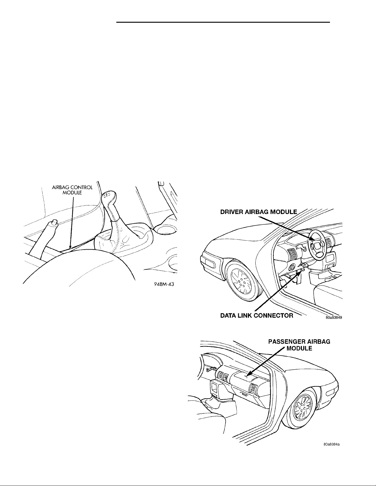
shift lever and the park brake lever (Fig. 1). The safing sensor provides confirmation of a crash, but does
not discriminate severity. The ACM monitors the system to determine the system readiness. The ACM
will store sufficient energy to deploy the airbags for
at least one second after the battery is disconnected.
The ACM contains on-board diagnostics, and will illuminate the AIRBAG warning lamp in the cluster
when a fault occurs. The warning equipment is
tested for six to eight seconds every time the vehicle
is started.
The airbag module contains a housing to which the
cushion, inflator and cover are attached to.
The driver side inflator assembly is mounted from
the back of the module housing. When supplied with
the proper electrical signal the inflator assembly will
produce a gas and discharge it directly into the cushion. A protective cover is fitted to the front of the
Driver Airbag Module and forms a decorative cover
in the center of the steering wheel. The Driver Airbag Module is mounted directly to the steering
wheel.
The Passenger Airbag Module is located beneath
the decorative cover of the instrument panel, facing
the passenger seat (Fig. 3).
The passenger inflator assembly is within the module housing. The module is mounted to the instrument panel retainer and support structure. When
supplied with the proper electrical signal the inflator
will produce a gas and discharge it directly into the
cushion. A protective cover is fitted into the instrument panel over the airbag module and forms a decorative cover.
Fig. 1 Airbag Control Module Location
CLOCKSPRING
The clockspring is mounted to the steering column
behind the steering wheel. The clockspring is used to
maintain a continuous electrical circuit between the
wiring harness and the:
• Driver’s airbag module
• Speed control switches
• Horn switch
The clockspring consists of a flat, ribbon like, electrically conductive tape which winds and unwinds
with the steering wheel rotation.
DRIVER AND PASSENGER AIRBAG MODULE
WARNING: NEVER DISASSEMBLE THE DRIVER OR
PASSENGER AIRBAG MODULE, THERE ARE NO
SERVICEABLE PARTS WITH IN THE MODULES.
The Driver Airbag Module located on the steering
wheel is the most visible part of the system (Fig. 2).
Fig. 2 Driver Airbag
Fig. 3 Passenger Airbag
Page 3
PL RESTRAINT SYSTEM 8M - 3
DIAGNOSIS AND TESTING
AIRBAG SYSTEM TEST
(1) Connect scan tool (DRB) to Data Link connector, located at right side of the steering column and
at the lower edge of the lower instrument panel.
(2) Turn the ignition key to ON position. Exit vehicle with scan tool. Use the latest version of the
proper cartridge.
(3) After checking that no one is inside the vehicle,
connect the battery negative terminal.
(4) Using the scan tool, read and record active
diagnostic code data.
(5) Read and record any stored diagnostic codes.
(6) Refer to the Passive Restraint Diagnostic Test
Manual if any diagnostic codes are found in Step 4 or
Step 5.
(7) Erase stored diagnostic codes if there are no
active diagnostic codes. If problems remain, diagnostic codes will not erase. Refer to the Passive
Restraint Diagnostic Test Manual to diagnose the
problem. If airbag warning lamp either fails to
light, or goes on and stays on, there is a system
malfunction. Refer to the Passive Restraint
Diagnostic Test Manual to diagnose the problem.
SERVICE PROCEDURES
they cannot be reused. Other driver airbag system
components are replaced if damaged.
PASSENGER AIRBAG
deployed:
cover, and any other components should be replaced
if damaged.
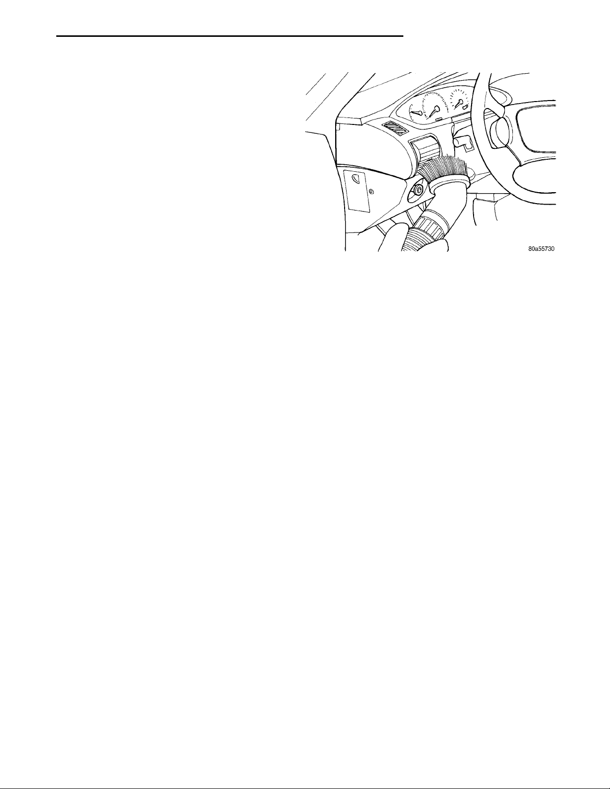
Fig. 4 Vacuum Heater and A/C Outlets
The component above must be replaced because
After a Passenger Airbag Module has been
• Passenger Airbag Module
• Right trim panel
The lower instrument panel knee blocker, top
CLEANUP PROCEDURE
Roll or fold the passenger airbag towards the
instrument panel surface and close the door over the
folded bag. Then tape the door shut.
Use a vacuum cleaner to remove any residual powder from the vehicle interior. Work from the outside
in to avoid kneeling or sitting in a contaminated
area. Vacuum the heater and A/C outlets as well (Fig.
4). If the heater or air conditioner was in RECIRC
mode at time of airbag deployment, operate blower
motor on low speed and vacuum powder residue
expelled from the heater and A/C outlets. Multiple
vacuum cleaning may to necessary to decontaminate
the interior of the vehicle.
NOTE: Dispose deployed airbag properly, contact
dealer or government agency for disposal recommendations.
SERVICE OF DEPLOYED AIRBAG MODULE
DRIVER AIRBAG
After a Driver Airbag Module has been deployed:
• Driver Airbag Module
• Clockspring assembly
HANDLING AIRBAG MODULE
DEPLOYED MODULE
The vehicle interior may contain a very small
amount of sodium hydroxide powder, a by-product of
airbag deployment. Sodium hydroxide powder can
irritate the skin, eyes, nose and throat. Wear safety
glasses, rubber gloves, and long sleeved clothing
when cleaning any of the powder residue from the
vehicle.
If you find that the cleanup is irritating your skin,
run cool water over the affected area. Also, if you
experience nasal or throat irritation, exit the vehicle
for fresh air until the irritation ceases. If irritation
continues, see a physician.
UNDEPLOYED
The airbag modules must be stored in its original
special container until used for service. At no time
should a source of electricity be permitted near the
inflator on the back of an airbag module. When carrying or handling an undeployed airbag module, the
trim side of the airbag should be pointing away from
the body to minimize possibility of injury if accidental deployment occurs. Do not place undeployed air-
Page 4
CENTER CONSOLEASSEMBLY PARK BRAKEHAND LEVERPAS-SENGERSEAT ATTACHINGSCREWS
CENTER CON-SOLE LINER CENTER CONSOLE WITHARMREST CENTER CONSOLELIDATTACHINGSCREWS
8M - 4 RESTRAINT SYSTEM PL
SERVICE PROCEDURES (Continued)
bag face down on a solid surface, the airbag will
propel into the air if accidentally deployment occurs.
MAINTENANCE INSPECTION
(1) Check that both front impact sensors are properly installed to the closure panel with three fasteners each. Repair as required.
(2) Check the airbag warning lamp for proper
operation as follows:
(a) Turn ignition switch to the ON position, the
airbag warning lamp should light. If not, test the
system using a scan tool and Passive Restraint
System Diagnostic Procedures Manual. Repair as
required.
(b) The airbag warning lamp lights, but fails to
go out after eight seconds. Test the system using a
scan tool and Passive Restraint System Diagnostic
Procedures Manual. Repair as required.
(c) After correcting active malfunction erase
stored diagnostic codes.
REMOVAL AND INSTALLATION
AIRBAG CONTROL MODULE (ACM)
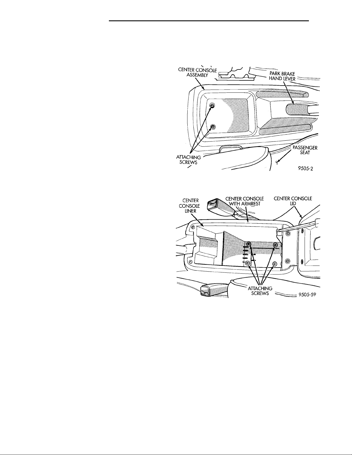
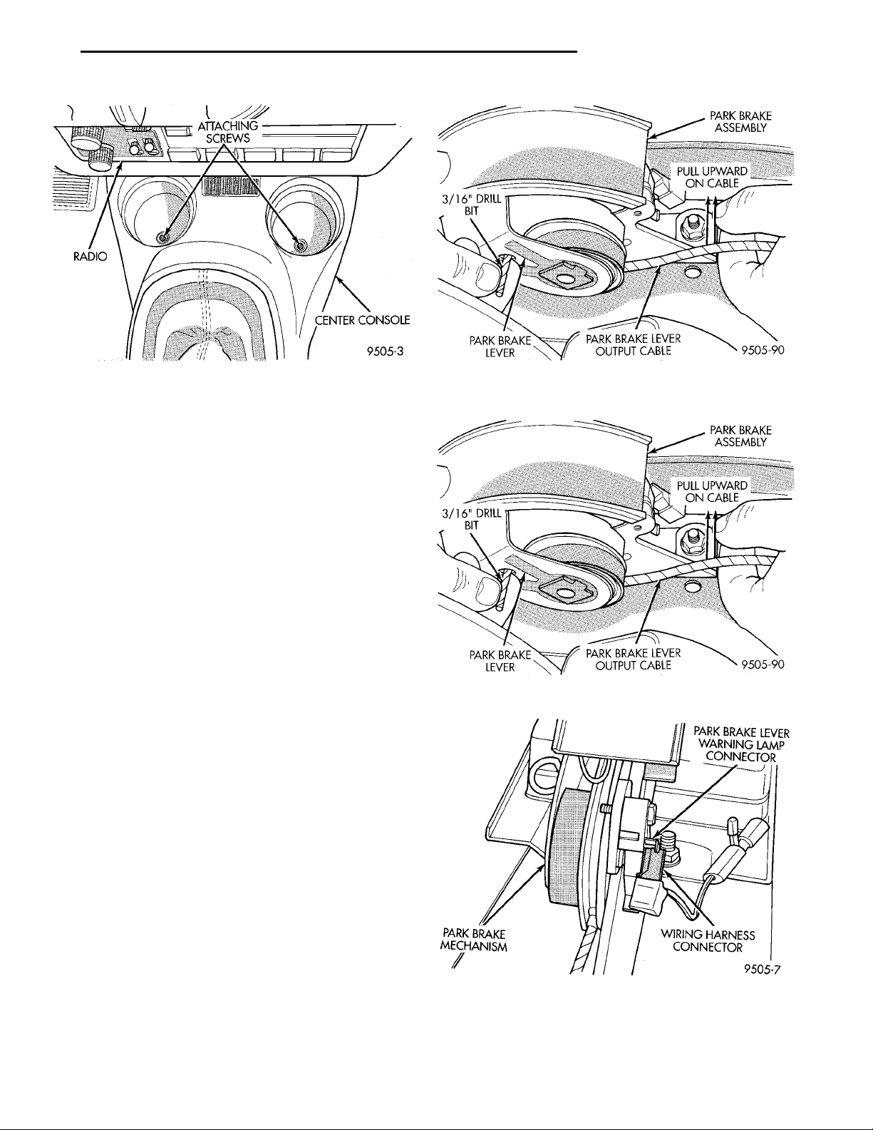
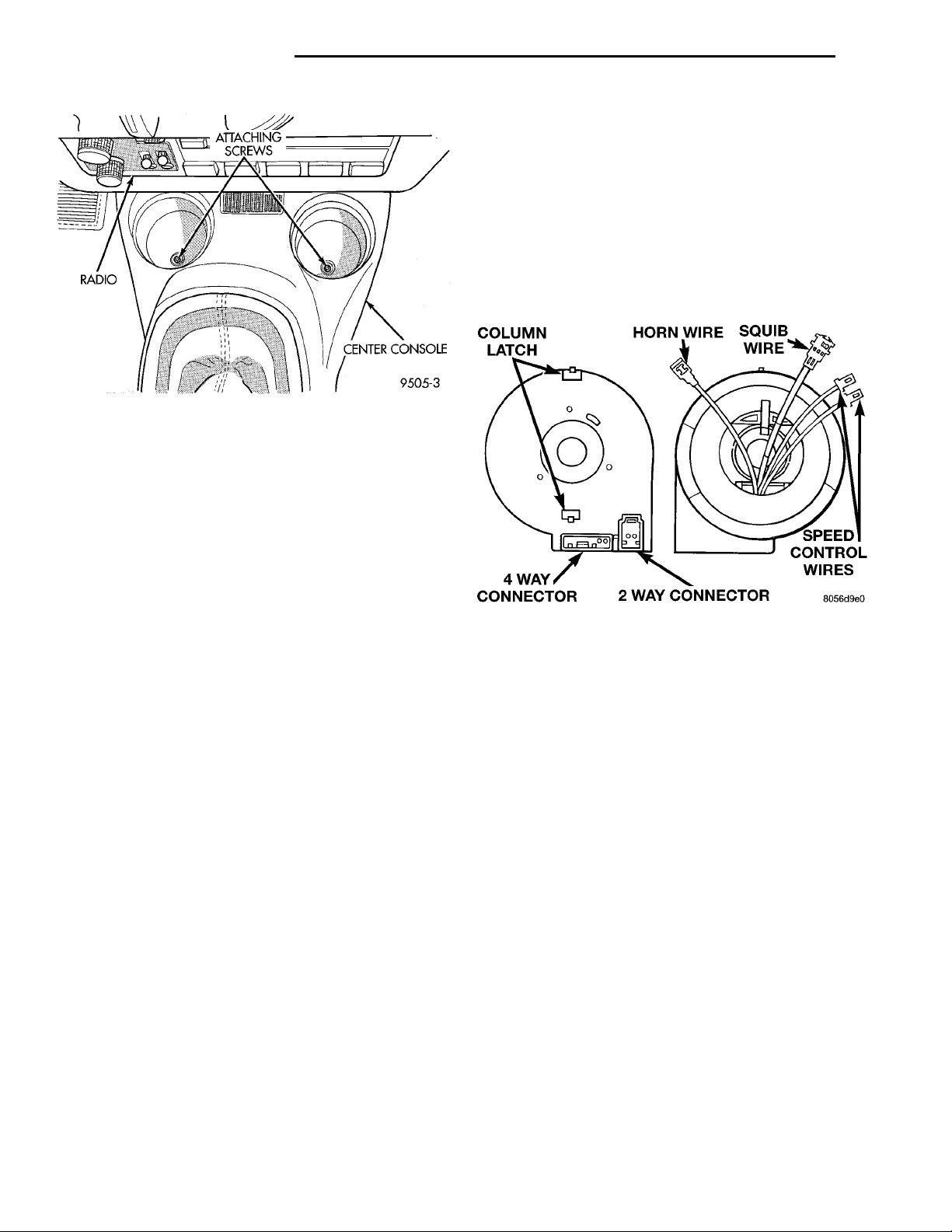
(4) Remove the two screws located in cup holders
(Fig. 7), attaching front of center console assembly to
console bracket.
Fig. 5 Attaching Screws At Rear Of Center Console
With/Without Arm Rest
REMOVAL
WARNING: THE ACM CONTAINS A SAFING SENSOR WHICH ENABLES THE SYSTEM TO DEPLOY
THE AIRBAGS. TO AVOID ACCIDENTAL DEPLOYMENT, NEVER CONNECT ACM ELECTRICALLY TO
THE SYSTEM WHILE VEHICLE BATTERY IS CONNECTED.
DISCONNECT AND ISOLATE THE BATTERY NEGATIVE (GROUND) CABLE BEFORE BEGINNING ANY
AIRBAG SYSTEM COMPONENT REMOVAL OR
INSTALLATION PROCEDURE. THIS WILL DISABLE
THE AIRBAG SYSTEM. FAILURE TO DISCONNECT
BATTERY COULD RESULT IN ACCIDENTAL AIRBAG
DEPLOYMENT AND POSSIBLE PERSONAL INJURY.
ALLOW SYSTEM CAPACITOR TO DISCHARGE
FOR 2 MINUTES BEFORE REMOVING ANY AIRBAG
COMPONENTS.
CAUTION: Failure to follow the parking brake service procedures can result in damage to the parking brake mechanism.
(1) Disconnect and isolate the battery negative
cable.
(2) Manual transaxle only, remove shifter knob
fastener and remove shifter knob.
(3) Remove screws attaching rear of center console
assembly to console bracket (Fig. 5) or (Fig. 6).
Fig. 6 Attaching Screws At Rear Of Center Console
With Arm Rest
(5) Raise park brake hand lever assembly as high
as it will go for required clearance to remove center
console.
(6) Remove center console assembly from vehicle.
Page 5
RADIO ATTACHINGSCREWSCENTER CON-SOLE
3/16” DRILL BITPARK BRAKEASSEMBLYPULL UPWARD ON CABLEPARK BRAKE LEVEROUTPUT CABLEPARK BRAKELEVER
3/16” DRILL BITPARK BRAKEASSEMBLYPULL UPWARD ON CABLEPARK BRAKE LEVEROUTPUT CABLEPARK BRAKELEVER
PARK BRAKE MECH-ANISMPARK BRAKE LEVER WARN-ING LAMP CONNECTORWIRING HARNESS CONNEC-TOR
PL RESTRAINT SYSTEM 8M - 5
REMOVAL AND INSTALLATION (Continued)
Fig. 7 Attaching Screws At Front Of Center Console
WARNING: THE AUTO ADJUSTING FEATURE OF
THIS PARKING BRAKE LEVER ASSEMBLY CONTAINS A CLOCK SPRING LOADED TO APPROXIMATELY 20 POUNDS. DO NOT RELEASE THE AUTO
ADJUSTER LOCKOUT DEVICE BEFORE INSTALLING CABLES INTO THE EQUALIZER. KEEP HANDS
OUT OF AUTO ADJUSTER SECTOR AND PAWL
AREA. FAILURE TO OBSERVE CAUTION IN HANDLING THIS MECHANISM COULD LEAD TO SERIOUS INJURY.
WHEN REPAIRS TO THE PARK BRAKE HAND
LEVER ASSEMBLY OR CABLES IS REQUIRED, THE
AUTO ADJUSTER MUST BE RELOADED AND
LOCKED OUT.
(7) Lower park brake lever handle.
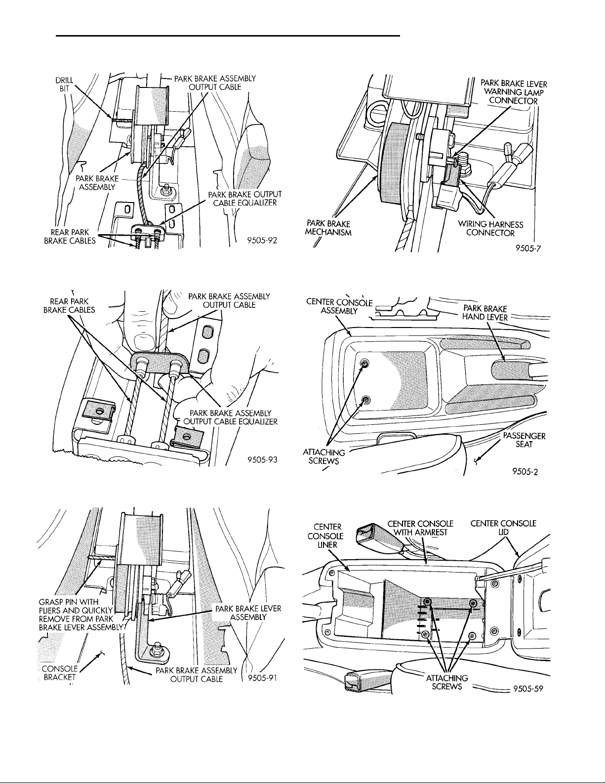
(8) Grasp park brake lever output cable by hand
and pull upward. Continue pulling on cable until a
3/16 in. drill bit can be inserted into handle and sector gear of park brake mechanism (Fig. 8). This will
lock the park brake mechanism and take tension off
park brake cables.
(9) Remove both rear park brake cables from the
park brake cable equalizer (Fig. 9).
(10) Remove wiring harness electrical connector
for brake warning light from park brake lever (Fig.
10).
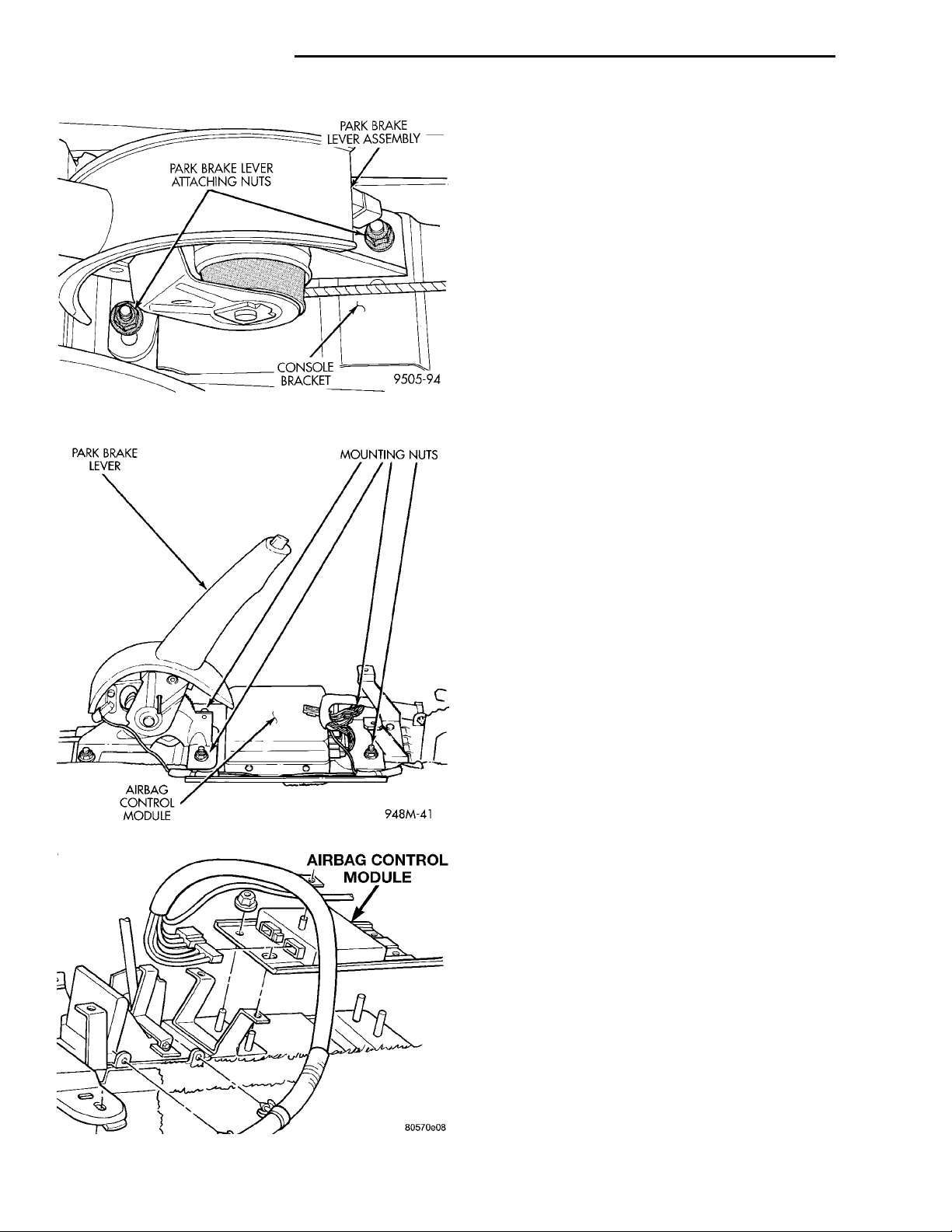
(11) Remove the two nuts (Fig. 11) attaching park
brake lever to console bracket. Remove park brake
lever mechanism from vehicle.
(12) Remove module mounting nuts and remove
module (Fig. 12).
(13) Disconnect ACM 4-way and 13-way connectors
(Fig. 13).
(14) Remove Airbag Control Module.
INSTALLATION
(1) Connect both ACM connectors and ensure both
connectors and all locking tabs are engaged.
Fig. 8 Locking Pin Installed In Park Brake
Mechanism
Fig. 9 Removing Park Brake Cables From Equalizer
Fig. 10 Brake Warning Lamp Connection To Park
Brake Lever
Page 6
PARK BRAKE LEVER MOUNTING NUTSAIRBAG CONTROL MODULE
PARK BRAKE LEVERATTACHING NUTSPARK BRAKELEVER ASSEM-BLYCONSOLE BRACKET
AIRBAG CONTROL MOD-
ULE
8M - 6 RESTRAINT SYSTEM PL
REMOVAL AND INSTALLATION (Continued)
CAUTION: USE SUPPLIED SCREWS ONLY
(2) Position ACM (arrow pointing forward) in the
console floor bracket, attach the nuts and tighten to
11 to 14 N·m (105 to 125 in. lbs.) torque.
NOTE: The park brake lever can be in any position
when releasing the auto adjuster. To ease installation of center console, it is advisable to pull park
brake lever handle all the way up before removing
lockout pin.
(3) Place park brake lever on console bracket.
Install and securely tighten the 2 attaching nuts.
(4) Install both rear park brake cables into equalizer on park brake lever output cable (Fig. 14) and
Fig. 11 Park Brake Lever Attachment To Console
Bracket
Fig. 12 Airbag Control Module
(Fig. 15).
(5) Ensure that park brake cable is correctly
installed and aligned with cable track on park brake
lever.
(6) Pull park brake lever handle all the way up.
(7) Firmly grasp park brake lever locking pin and
quickly remove it from the park brake lever mechanism (Fig. 16) This will allow the park brake lever
mechanism to correctly adjust the park brake cables.
(8) Connect electrical connector for brake warning
lamp onto terminal on park brake lever assembly
(Fig. 17).
(9) Cycle park brake lever once to position park
brake cables. Then return the park brake lever its
released position. Check the rear wheels of the vehicle. They should rotate freely without dragging.
(10) Raise park brake lever to its fully engaged
position. This is necessary to allow installation of the
center console.
(11) Install center console assembly.
(12) Install the four center console assembly
attaching screws (Fig. 18), (Fig. 19) and (Fig. 20).
(13) Replace shifter knob and fastener.
(14) Do not connect battery negative cable. Refer
to Diagnosis and Testing for Airbag System Test for
the proper procedures.
Fig. 13 ACM Connectors
Page 7
DRILL BIT PARK BRAKE ASSEMBLY OUT-PUT CABLEPARK BRAKEOUTPUT CABLEEQUALIZER
PARK BRAKEASSEMBLY
REAR PARK BRAKECABLES PARK BRAKE ASSEMBLYOUTPUT CABLEPARK BRAKE ASSEMBLY OUTPUTCABLE EQUALIZER
PARK BRAKEASSEMBLY OUT-PUT CABLE
CONSOLE BRACKET
PL RESTRAINT SYSTEM 8M - 7
PARK BRAKE LEVER ASSEM-
REAR PARK BRAKE CABLES
GRASP PIN WITH PLIERS
AND QUICKLY REMOVE
BLY
FROM PARK BRAKE
LEVER ASSEMBLY
CENTER CONSOLEASSEMBLY PARK BRAKEHAND LEVERPAS-SENGERSEAT ATTACHINGSCREWS
CENTER CON-SOLE LINER CENTER CONSOLE WITHARMREST CENTER CONSOLELIDATTACHINGSCREWS
PARK BRAKE MECH-ANISMPARK BRAKE LEVER WARN-ING LAMP CONNECTORWIRING HARNESS CONNEC-TOR
REMOVAL AND INSTALLATION (Continued)
Fig. 14 Park Brake Cables Properly Installed In
Equalizer
Fig. 15 Rear Park Brake Cable Installation On
Equalizer
Fig. 17 Brake Warning Lamp Connection To Park
Brake Lever
Fig. 18 Attaching Screws At Rear Of Center Console
With/Without Arm Rest
Fig. 16 Removing Lockout Pin From Park Brake
Lever Assembly
Fig. 19 Attaching Screws At Rear Of Center Console
With Arm Rest
Page 8
RADIO ATTACHINGSCREWSCENTER CON-SOLE
COLUMNLATCH HORN WIRE SQUIB WIRESPEED CON-TROL WIRES2 WAY CON-NECTOR4 WAY CON-NECTOR
8M - 8 RESTRAINT SYSTEM PL
REMOVAL AND INSTALLATION (Continued)
wiring harness at the base of the clockspring (Fig.
21).
(10) Unlatch and remove clockspring assembly
from steering shaft. The clockspring cannot be
repaired, and must be replaced if faulty.
(11) Rotate clockspring rotor a half turn (180
degrees) to the left (counter clockwise).
(12) Lock the clockspring rotor in the center position as follows: Insert a paper clip wire through the
hole in the rotor at the 10 O’clock position and bend
to prevent it from falling out.
Fig. 20 Attaching Screws At Front Of Center
Console
CLOCKSPRING
REMOVAL
WARNING: DISCONNECT AND ISOLATE THE BATTERY NEGATIVE (GROUND) CABLE BEFORE
BEGINNING ANY AIRBAG SYSTEM COMPONENT
REMOVAL OR INSTALLATION PROCEDURE. THIS
WILL DISABLE THE AIRBAG SYSTEM. FAILURE TO
DISCONNECT BATTERY COULD RESULT IN ACCIDENTAL AIRBAG DEPLOYMENT AND POSSIBLE
PERSONAL INJURY. ALLOW SYSTEM CAPACITOR
TO DISCHARGE FOR 2 MINUTES BEFORE REMOVING ANY AIRBAG COMPONENTS.
(1) Place the front road wheels in the straight
ahead position then:
• Rotate the steering wheel half turn (180
degrees) to the right (clockwise)
• Lock column with ignition lock cylinder.
(2) Disconnect and isolate the battery negative
cable.
(3) Wait two minutes for the reserve capacitor to
discharge before removing non-deployed module.
(4) Remove speed control switch mounting screws,
switches and disconnect the wire connectors or
remove covers.
(5) Remove the Driver Airbag Module attaching
bolts from under the speed control switches or covers.
(6) Lift module and disconnect the airbag and horn
wire connectors.
(7) Remove the steering wheel, refer to Steering
Wheel removal procedures.
(8) Remove upper and lower steering column
shrouds to gain access to clockspring wiring.
(9) Disconnect the 2-way and 4-way connectors
between the clockspring and the instrument panel
Fig. 21 Clockspring
INSTALLATION
(1) Confirm that:
• The steering wheel position is a half turn (180
degrees) to the right (clockwise)
• The column is locked with the ignition cylinder
lock.
• Check that the turn signal stalk is in the neu-
tral position
• When reusing the clockspring, remove locking
wire and rotate clockspring rotor one half turn (180
degrees) to the right (clockwise). Locate the clockspring on the steering shaft and push down on the
rotor until the clockspring is fully seated on the
steering column.
• When installing a new clockspring, position the
front wheels straight a head. Remove grenade pin.
Rotate clockspring rotor one half turn (180 degrees)
to the right (clockwise).
(2) Connect the clockspring to the instrument
panel harness, ensure wiring is properly routed.
Then check that the connectors, locking tabs are
properly engaged and the halo lamp wire is in position.
(3) Install steering column shrouds. Be sure all
wires are inside of shrouds.
(4) Install steering wheel ensuring the flats on hub
align with the clockspring. Pull the horn, airbag and
Page 9
AIRBAG SQUIB WIREAIRBAG MODULEHORN WIRE
SPEED CONTROL CONNEC-TORS
PL RESTRAINT SYSTEM 8M - 9
REMOVAL AND INSTALLATION (Continued)
speed control leads through the larger slot. Ensure
leads do not get pinched under the steering wheel.
(5) Route speed control wires under and behind
the airbag module mounting tabs.
(6) Connect the horn lead wire and the airbag lead
wire to the airbag module.
(7) Install the airbag module and tighten bolts to
12 to 14 N·m (105 to 125 in. lbs.) torque.
(8) Connect the speed control wires to the switches
and install switches. Tighten screws to 2 N·m (20 in.
lbs.) torque.
(9) Do not connect the battery negative cable.
Refer to Diagnosis and Testing for Airbag System
Test procedures.
DRIVER AIRBAG MODULE
REMOVAL
WARNING: DISCONNECT AND ISOLATE THE BATTERY NEGATIVE (GROUND) CABLE BEFORE
BEGINNING ANY AIRBAG SYSTEM COMPONENT
REMOVAL OR INSTALLATION PROCEDURE. THIS
WILL DISABLE THE AIRBAG SYSTEM. FAILURE TO
DISCONNECT BATTERY COULD RESULT IN ACCIDENTAL AIRBAG DEPLOYMENT AND POSSIBLE
PERSONAL INJURY. ALLOW SYSTEM CAPACITOR
TO DISCHARGE FOR 2 MINUTES BEFORE REMOVING ANY AIRBAG COMPONENTS.
When removing a deployed module, rubber gloves,
eye protection and long sleeved shirt should be worn,
as there may be deposits on the surface which could
irritate the skin and eyes.
(1) Disconnect and isolate the battery negative
cable.
(2) Remove speed control switches or covers from
steering wheel armature and disconnect the wires.
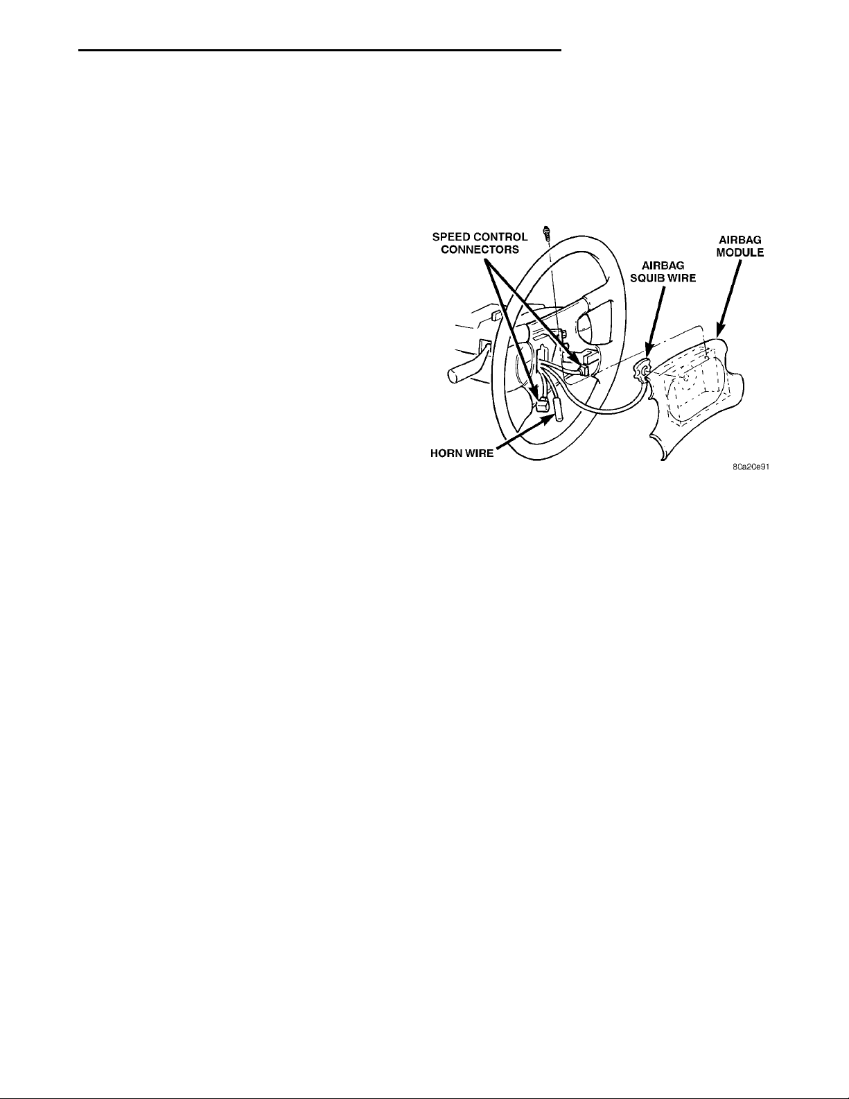
(3) Remove two bolts attaching Driver Airbag Module from the sides of steering wheel (Fig. 22).
(4) Lift module and disconnect airbag squib wire
connector and horn wire.
(5) Remove Driver Airbag Module.
(6) When replacing a deployed driver airbag module, the clockspring must also be replaced. Refer to
Clockspring Removal and Installation for proper procedure.
(4) Install covers to the steering wheel armature
or connect the wire connectors to the speed control
switches and install switches. Tighten fastener to 2
N·m (20 in. lbs.) TORQUE.
(5) Do not connect battery negative cable. Refer to
Diagnosis and Testing for Airbag System Test procedures.
Fig. 22 Driver Airbag Module
PASSENGER AIRBAG MODULE
NON-DEPLOYED MODULE
REMOVAL
When removing a module for any reason other
than DEPLOYMENT.
(1) Disconnect and isolate the battery negative
cable.
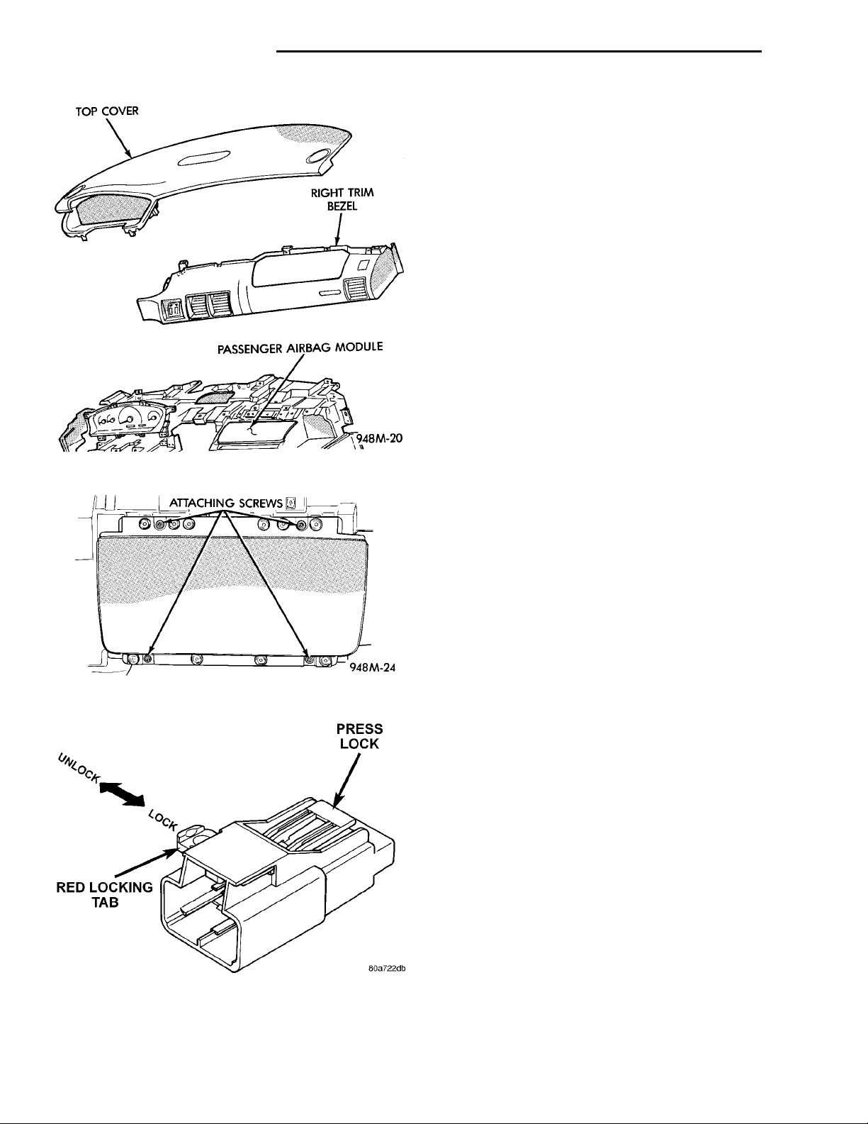
(2) Remove instrument panel top cover (Fig. 23).
(3) Remove instrument panel right trim bezel.
(4) Open glove box and push the sides inward
allowing the door bumper to pass and box to open.
(5) Remove the four trim screws which attach the
Passenger Airbag Module to the top instrument
panel (Fig. 24).
(6) Remove two module attaching nuts from the
support structure.
(7) Lift module up until the wire connector is visible and disconnect the 4-way wire connector from
module. Unlock the red locking tab and compress
lock to release the connector (Fig. 25).
INSTALLATION
For installation, reverse the above procedures.
(1) Connect the squib wire to the module. Make
airbag connection by pressing straight in on the connector. The connector should be fully seated feel for
positive snap to assure positive connection.
(2) Connect the horn wire.
(3) Install two bolts and tighten to 10 to 11 N·m
(90 to 100 in. lbs.) torque.
INSTALLATION
For installation, reverse the above procedures.
Ensure that the red locking tab is in the lock position
after installing the connector. Tighten trim screws to
2 N·m (20 in. lbs.) torque. Tighten the module nuts to
22 to 34 N·m (200 to 300 in. lbs.) torque. Do not connect battery negative cable. Refer to Diagnosis and
Testing for Airbag System Test procedures.
Page 10
LOCKPRESS LOCKRED LOCKING TAB
TOP COVER RIGHT TRIM BEZELPASSENGER AIRBAG MOD-ULE
UNLOCK
ATTACHING SCREWS
8M - 10 RESTRAINT SYSTEM PL
REMOVAL AND INSTALLATION (Continued)
DEPLOYED MODULE
REMOVAL
When removing a deployed module, rubber gloves,
eye protection, and a long-sleeved shirt should be
worn, as there may be deposits on the surface which
could irritate the skin and eyes.
(1) Disconnect and isolate the battery negative
cable.
(2) Roll/fold airbag towards instrument panel.
(3) Close door over folded airbag and tape door
closed.
(4) Remove instrument panel top cover (Fig. 23).
(5) Remove instrument panel right trim panel.
(6) Open glove box and push the sides inward
allowing the door bumper to pass and box to open.
(7) Remove the four trim screws which attach the
module to the top instrument panel (Fig. 24).
(8) Remove two module attaching nuts from the
support structure.
(9) Lift module up until the wire connector is visi-
Fig. 23 Instrument Panel
ble and disconnect the 4-way wire connector from
module. Unlock the red locking tab and compress
lock to release the connector.
Fig. 24 Passenger Airbag Module
Fig. 25 Airbag Module Connector
INSTALLATION
For installation, reverse the above procedures.
Ensure that the red locking tab is in the lock position
after installing the connector. Tighten trim screws to
2 N·m (20 in. lbs.) torque. Tighten the module nuts to
22 to 34 N·m (200 to 300 in. lbs.) torque. Do not connect battery negative cable. Refer to Diagnosis and
Testing for Airbag System Test procedures.
STEERING WHEEL
WARNING: DISCONNECT AND ISOLATE THE BATTERY NEGATIVE (GROUND) CABLE BEFORE
BEGINNING ANY AIRBAG SYSTEM COMPONENT
REMOVAL OR INSTALLATION PROCEDURE. THIS
WILL DISABLE THE AIRBAG SYSTEM. FAILURE TO
DISCONNECT BATTERY COULD RESULT IN ACCIDENTAL AIRBAG DEPLOYMENT AND POSSIBLE
PERSONAL INJURY.
ALLOW SYSTEM CAPACITOR TO DISCHARGE
FOR 2 MINUTES BEFORE REMOVING ANY AIRBAG
COMPONENTS.
REMOVAL
(1) Adjust the steering wheel so that the tires are
in the straight ahead position then:
• Rotate the steering wheel half turn (180
degrees) to the right (clockwise)
• Lock column with the ignition cylinder lock
(2) Disconnect and isolate the battery negative
cable.
Page 11

PL RESTRAINT SYSTEM 8M - 11
REMOVAL AND INSTALLATION (Continued)
(3) Remove the speed control switches and discon-
nect the wire connectors or covers.
(4) Remove the Driver Airbag Module attaching
bolts from the back of steering wheel.
(5) Lift module and disconnect the airbag and horn
wire connectors.
(6) Remove steering wheel retaining nut.
(7) Remove the steering wheel with a steering
wheel puller. While removing the steering wheel take
care to feed the wires gently through the holes in the
clockspring armature.
INSTALLATION
(1) Confirm that:
• The steering wheel position is a half turn (180
degrees) to the right (clockwise)
• The column is locked with the ignition cylinder
lock.
• Check that the turn signal stalk is in the neu-
tral position
(2) Install the steering wheel ensuring the flats on
hub align with the clockspring. Pull the horn lead,
airbag and speed control leads through the larger
slot. Ensure leads do not get pinched under the steering wheel.
(3) Install the steering wheel retaining nut, and
tighten it to 61 N·m (45 ft. lbs.) torque.
(4) Install the airbag module. Refer to Driver Airbag Module Removal and Installation for proper procedures.
(5) Do not connect the battery negative cable.
Refer to Diagnosis and Testing for Airbag System
Test procedures.
ADJUSTMENTS
CLOCKSPRING CENTERING PROCEDURE
If the rotating tape within the clockspring is not
positioned properly with the steering wheel and the
front wheels, the clockspring may fail during use.
The following procedure MUST BE USED to center
the clockspring if:
• The clockspring is not known to be properly
positioned
• The front wheels were moved
• The steering wheel was moved from the half
turn (180 degrees) to the right (clockwise) position.
WARNING: DISCONNECT AND ISOLATE THE BATTERY NEGATIVE (GROUND) CABLE BEFORE
BEGINNING ANY AIRBAG SYSTEM COMPONENT
REMOVAL OR INSTALLATION PROCEDURE. THIS
WILL DISABLE THE AIRBAG SYSTEM. FAILURE TO
DISCONNECT BATTERY COULD RESULT IN ACCIDENTAL AIRBAG DEPLOYMENT AND POSSIBLE
PERSONAL INJURY.
ALLOW SYSTEM CAPACITOR TO DISCHARGE
FOR 2 MINUTES BEFORE REMOVING ANY AIRBAG
COMPONENTS.
(1) Remove clockspring, refer to Clockspring
Removal.
(2) Rotate the clockspring rotor in the CLOCKWISE DIRECTION to the end of travel. Do not apply
excessive torque.
(3) From the end of travel, rotate the rotor two full
turns and a half in the counterclockwise direction.
The horn wire and the squib wire should end up at
the bottom. If not, rotate the rotor counter clockwise
until the wires are properly orientated, but not more
than half turn (180 degrees). Engage clockspring
locking mechanism.
(4) For installation, refer to Clockspring Installation
(5) Do not connect battery negative cable. Refer to
Diagnosis and Testing for Airbag System Test
procedures.
Page 12

 Loading...