

Page 1

PL LAMPS 8L - 1
LAMPS
CONTENTS
page page
BULB APPLICATION ..................... 15
HEADLAMP ALIGNMENT .................. 5
LAMP BULB SERVICE .................... 8
LAMP DIAGNOSIS
INDEX
page page
GENERAL INFORMATION
DAYTIME RUNNING LAMP MODULE ......... 1
GENERAL INFORMATION ................. 1
SAFETY PRECAUTIONS .................. 1
GENERAL INFORMATION
GENERAL INFORMATION
Each vehicle is equipped with various lamp assemblies. A good ground is necessary for proper lighting
operation. Grounding is provided by the lamp socket
when it comes in contact with the metal body, or
through a separate ground wire.
When changing lamp bulbs check the socket for
corrosion. If corrosion is present, clean it with a wire
brush and coat the inside of the socket lightly with
Mopar Multi-Purpose Grease or equivalent.
SAFETY PRECAUTIONS
WARNING: EYE PROTECTION SHOULD BE USED
WHEN SERVICING GLASS COMPONENTS. PERSONAL INJURY CAN RESULT.
LAMP DIAGNOSIS ....................... 1
LAMP SERVICE ........................ 11
LAMP SYSTEMS ....................... 14
DIAGNOSIS AND TESTING
DIAGNOSTIC PROCEDURES .............. 1
FOG LAMP DIAGNOSIS ................... 4
HEADLAMP DIAGNOSIS .................. 2
When it is necessary to remove components to service another, it should not be necessary to apply
excessive force or bend a component to remove it.
Before damaging a trim component, verify hidden
fasteners or captured edges are not holding the component in place.
DAYTIME RUNNING LAMP MODULE
PL vehicles built for use in Canada are equipped
with a Daytime Running Lamp (DRL) system. The
DRL system operates the headlamps at 50% illumination with the headlamp switch OFF, park brake
released and the ignition ON. The DRL system is
controlled by the Daytime Running Lamp Module.
The DRL module overrides the headlamp switch
when the headlamps are turned OFF. The headlamps
operate normally when the headlamps are turned
ON.
CAUTION: Do not touch the glass of halogen bulbs
with fingers or other possibly oily surface, reduced
bulb life will result.
Do not use bulbs with higher candle power than
indicated in the Bulb Application table at the end of
this group. Damage to lamp can result.
Do not use fuses, circuit breakers or relays having greater amperage value than indicated on the
fuse panel or in the Owners Manual.
DIAGNOSIS AND TESTING
DIAGNOSTIC PROCEDURES
When a vehicle experiences problems with the
headlamp system, verify the condition of the battery
connections, charging system, headlamp bulbs, wire
connectors, relay, high beam dimmer switch and
headlamp switch. Refer to Group 8W, Wiring Diagrams for component locations and circuit information.
Page 2

8L - 2 LAMPS PL
DIAGNOSIS AND TESTING (Continued)
HEADLAMP DIAGNOSIS
Always begin any diagnosis by testing all of the
fuses and circuit breakers in the system. Refer to
Group 8W, Wiring Diagrams.
Conventional and halogen headlamps are interchangeable. It is recommended that they not be
intermixed on a given vehicle.
Page 3

PL LAMPS 8L - 3
DIAGNOSIS AND TESTING (Continued)
.
HEADLAMP DIAGNOSIS
CONDITION POSSIBLE CAUSES CORRECTION
HEADLAMPS ARE DIM WITH
ENGINE IDLING OR IGNITION
TURNED OFF.
HEADLAMP BULBS BURN OUT
FREQUENTLY.
HEADLAMPS ARE DIM WITH
ENGINE RUNNING ABOVE IDLE.*
1. Loose or corroded battery
cables.
2. Loose or worn generator drive
belt.
3. Charging system out too low. 3. Test and repair charging system,
4. Battery has insufficient charge. 4. Test battery state-of-charge, refer
5. Battery is sulfated or shorted. 5. Load test battery, refer to Group
6. Poor lighting circuit Z1-ground. 6. Test for voltage drop across
7. Both headlamp bulbs defective. 7. Replace both headlamp bulbs.
1. Charging system output too high. 1. Test and repair charging system,
2. Loose or corroded terminals or
splices in circuit.
1. Charging system output too low. 1. Test and repair charging system,
2. Poor headlamp circuit ground. 2. Test voltage drop across
3. High resistance in headlamp
circuit.
4. Both headlamp bulbs defective. 4. Replace both headlamp bulbs.
1. Clean and secure battery cable
clamps and posts.
2. Adjust or replace generator drive
belt.
refer to Group 8A.
to Group 8A.
8A.
Z1-ground locations, refer to Group
8W.
refer to Group 8A.
2. Inspect and repair all connectors
and splices, refer to Group 8W.
refer to Group 8A.
Z1-ground, refer to Group 8W.
3. Test amperage draw of headlamp
circuit.
HEADLAMPS FLASH RANDOMLY. 1. Poor headlamp circuit ground. 1. Repair circuit ground, refer to
Group 8W.
HEADLAMPS DO NOT
ILLUMINATE.
* Canada vehicles must have lamps ON.
2. High resistance in headlamp
circuit.
3. Faulty headlamp switch circuit
breaker.
4. Loose or corroded terminals or
splices in circuit.
1. No voltage to headlamps. 1. Replace fuse, refer to Group 8W.
2. No ground at headlamps. 2. Repair circuit ground, refer to
3. Faulty headlamp switch. 3. Replace headlamp switch.
4. Faulty headlamp dimmer switch. 4. Replace headlamp dimmer
5. Broken connector terminal or
wire splice in headlamp circuit.
2. Test amperage draw of headlamp
circuit.
3. Replace headlamp switch.
4. Repair connector terminals or
splices, refer to Group 8W.
Group 8W.
switch.
5. Repair connector terminal or wire
splices.
Page 4

8L - 4 LAMPS PL
DIAGNOSIS AND TESTING (Continued)
FOG LAMP DIAGNOSIS
CONDITION POSSIBLE CAUSES CORRECTION
FOG LAMPS ARE DIM WITH
ENGINE IDLING OR IGNITION
TURNED OFF.
FOG LAMP BULBS BURN OUT
FREQUENTLY.
FOG LAMPS ARE DIM WITH
ENGINE RUNNING ABOVE IDLE.
1. Loose or corroded battery
cables.
2. Loose or worn generator drive
belt.
3. Charging system output too low. 3. Test and repair charging system,
4. Battery has insufficient charge. Test battery state-of-charge, refer to
5. Battery is sulfated or shorted. 5. Load test battery, refer to Group
6. Poor lighting circuit Z1-ground. 6. Test for voltage drop across
7. Both fog lamp bulbs defective. 7. Replace both lamp bulbs.
1. Charging system output too high. 1. Test and repair charging system,
2. Loose or corroded terminals or
splices in circuit.
1. Charging system output too low. 1. Test and repair charging system,
2. Poor fog lamp circuit ground. 2. Test voltage drop across
3. High resistance in fog lamp
circuit.
4. Both fog lamp bulbs defective. 4. Replace both fog lamp bulbs.
1. Clean and secure battery cable
clamps and posts.
2. Adjust or replace generator drive
belt.
refer to Group 8A.
Group 8A.
8A.
Z1-ground locations, refer to Group
8W.
refer to Group 8A.
2. Inspect and repair all connectors
and splices, refer to Group 8W.
refer to Group 8A.
Z1-ground, refer to Group 8W.
3. Test amperage draw of fog lamp
circuit.
FOG LAMPS FLASH RANDOMLY. 1. Poor fog lamp circuit ground. 1. Repair circuit ground, refer to
Group 8W.
FOG LAMPS DO NOT
ILLUMINATE.
2. High resistance in fog lamp
circuit.
3. Faulty fog lamp switch circuit
breaker.
4. Loose or corroded terminals or
splices in circuit.
1. Blown fuse for log lamps. 1. Replace fuse, refer to Group 8W.
2. No ground at fog lamps. 2. Repair circuit ground, refer to
3. Faulty fog lamp switch. 3. Replace fog lamp switch.
4. Broken connector terminal or
wire splice in fog lamp circuit.
2. Test amperage draw of fog lamp
circuit.
3. Replace fog lamp switch.
4. Repair connector terminals or
splices, refer to Group 8W.
Group 8W.
4. Repair connector terminal or wire
splices.
Page 5

PL LAMPS 8L - 5
HEADLAMP ALIGNMENT
INDEX
page page
GENERAL INFORMATION
HEADLAMP ALIGNMENT .................. 5
SERVICE PROCEDURES
HEADLAMP ALIGNMENT PREPARATION ...... 5
ADJUSTMENTS
FOG LAMP ALIGNMENT .................. 5
GENERAL INFORMATION
HEADLAMP ALIGNMENT
Headlamps can be aligned using the screen method
provided in this section. Alignment Tool C4466-A or
equivalent can also be used. Refer to instructions
provided with the tool for proper procedures. The
preferred headlamp alignment setting is 0 for
the left/right adjustment and 0 for the up/down
adjustment.
SERVICE PROCEDURES
HEADLAMP ALIGNMENT PREPARATION
(1) Verify headlamp dimmer switch and high beam
indicator operation.
(2) Inspect and correct damaged or defective components that could interfere with proper headlamp
alignment.
(3) Verify proper tire inflation.
(4) Clean headlamp lenses.
(5) Verify that luggage area is not heavily loaded.
(6) Fuel tank should be FULL. Add 2.94 kg (6.5
lbs.) of weight over the fuel tank for each estimated
gallon of missing fuel.
ADJUSTMENTS
HEADLAMP ADJUSTMENT USING ALIGNMENT
SCREEN
ALIGNMENT SCREEN PREPARATION
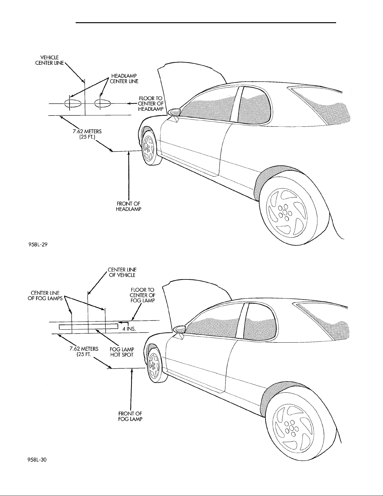
(1) Position vehicle on a level surface perpendicular to a flat wall 7.62 meters (25 ft) away from front
of headlamp lens (Fig. 1).
(2) If necessary, tape a line on the floor 7.62
meters (25 ft) away from and parallel to the wall.
(3) From the floor up 1.27 meters (5 ft), tape a line
on the wall at the centerline of the vehicle. Sight
along the centerline of the vehicle (from rear of vehicle forward) to verify accuracy of the line placement.
HEADLAMP ADJUSTMENT USING ALIGNMENT
SCREEN ............................. 5
SPECIAL TOOLS
SPECIAL TOOLS—HEADLAMP ALIGNMENT . . . 7
(4) Rock vehicle side-to-side three times to allow
suspension to stabilize.
(5) Jounce front suspension three times by pushing
downward on front bumper and releasing.
(6) Measure the distance from the center of headlamp lens to the floor. Transfer measurement to the
alignment screen (with tape). Use this line for
up/down adjustment reference.
(7) Measure distance from the centerline of the
vehicle to the center of each headlamp being aligned.
Transfer measurements to screen (with tape) to each
side of vehicle centerline. Use these lines for left/
right adjustment reference.
HEADLAMP ADJUSTMENT
A properly aimed low beam headlamp will project
the top edge of low beam hot spot on the alignment
screen from 50 mm (2 in.) above to 50 mm (2 in.)
below the headlamp centerline. The side- to-side left
edge of low beam hot spot should be from 50 mm (2
in.) left to 50mm (2 in.) right of headlamp centerline
(Fig. 1). The preferred headlamp alignment is 0
for the up/down adjustment and 0 for the left/
right adjustment. The high beams on a vehicle
with aero headlamps cannot be aligned. The high
beam pattern should be correct when the low beams
are aligned properly.
To adjust headlamp alignment, rotate alignment
screws to achieve the specified low beam hot spot
pattern.
FOG LAMP ALIGNMENT
Prepare an alignment screen. Refer to Alignment
Screen Preparation paragraph in this section. Disengage the wire connectors from the back of the headlamp bulbs to disable the headlamps. This will allow
a more accurate projection reading of the fog lamps.
Turn on the headlamp switch and actuate the fog
lamp switch. A properly aligned fog lamp will project
a pattern on the alignment screen 100 mm (4 in.)
below the fog lamp centerline and straight ahead
(Fig. 2).
Page 6
VEHICLE CENTER LINE HEADLAMP CEN-TER LINEFLOOR TOCENTER OFHEADLAMPFRONT OF HEADLAMP7.62 METERS(25 FT.)
8L - 6 LAMPS PL
SPECIAL TOOLS (Continued)
CENTER LINE OF VEHICLEFLOOR TO CENTER FOGLAMP4 INS.FOG LAMP HOT SPOTFRONT OF FOG LAMP7.62 METERS(25 FT.)CENTER LINE OF FOGLAMPS
Fig. 1 Headlamp Alignment Screen—Typical
Fig. 2 Lamp Alignment Screen
Page 7
PL LAMPS 8L - 7
SPECIAL TOOLS
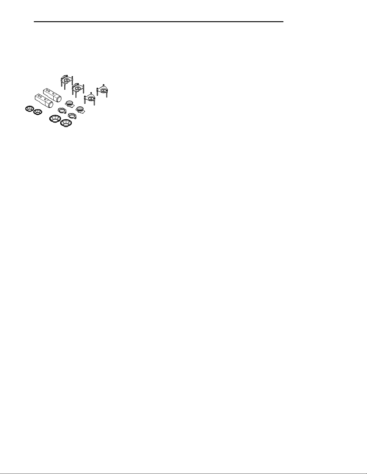
SPECIAL TOOLS—HEADLAMP ALIGNMENT
Headlamp Aiming Kit C-4466–A
Page 8
RADIATOR CLO-SURE PANEL HEADLAMP RETAININGRINGHEADLAMPBULB
8L - 8 LAMPS PL
BULB FOG LAMP
LAMP BULB SERVICE
INDEX
page page
REMOVAL AND INSTALLATION
CENTER HIGH MOUNTED STOP LAMP BULB . . 9
DOME LAMP BULB ..................... 10
FOG LAMP BULB ........................ 8
FRONT SIDE MARKER LAMP BULB ......... 9
HEADLAMP BULB ....................... 8
LICENSE PLATE LAMP BULB ............. 10
REMOVAL AND INSTALLATION
HEADLAMP BULB
REMOVAL
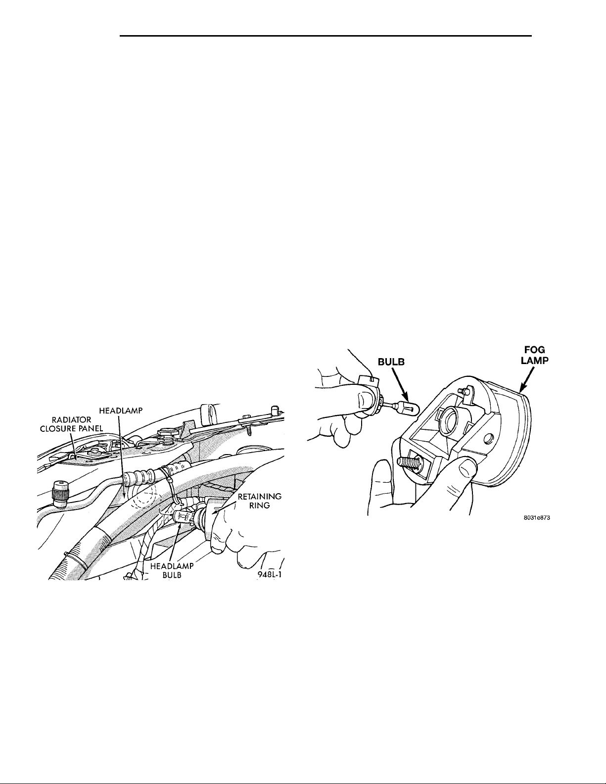
(1) Release hood latch and open hood.
(2) Disengage wire connector from headlamp bulb
connector.
(3) Remove retaining ring holding bulb to back of
headlamp module.
(4) Pull bulb from back of headlamp module (Fig.
1).
PARK AND TURN SIGNAL LAMP BULB ....... 8
REAR CARGO LAMP BULB ............... 10
TAIL, STOP, BACK-UP AND TURN SIGNAL
LAMP BULB .......................... 9
UNDERHOOD LAMP BULB ............... 10
VISOR VANITY LAMP BULB ............... 10
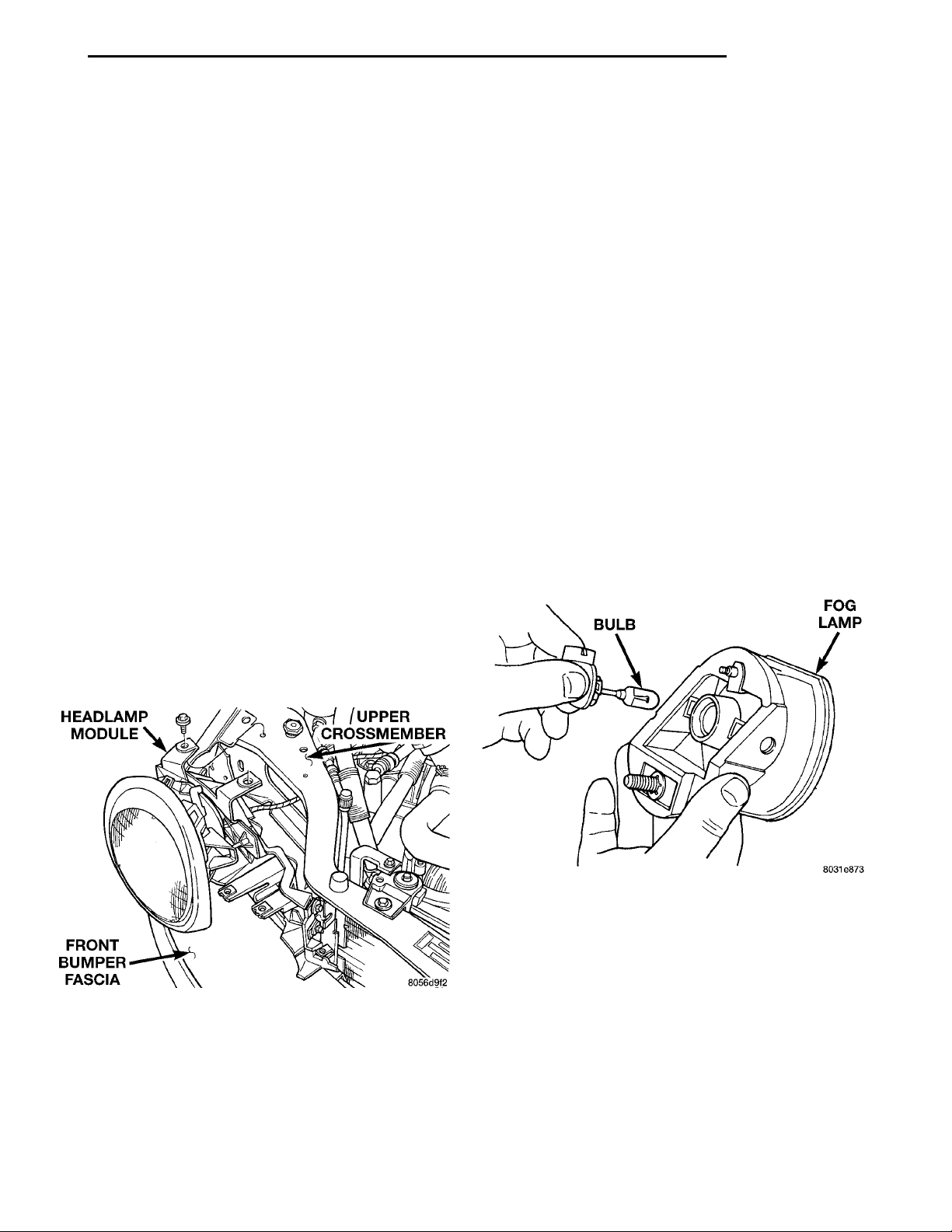
FOG LAMP BULB
REMOVAL
(1) Remove fog lamp from behind fascia.
(2) Disengage wire connector from fog lamp bulb
base.
(3) Remove bulb from lamp (Fig. 2).
Fig. 1 Headlamp Bulb
INSTALLATION
CAUTION: Do not touch the glass of halogen
bulbs with fingers or other possibly oily surface,
reduced bulb life will result.
Reverse the preceding operation.
Fig. 2 Fog Lamp Bulb
INSTALLATION
CAUTION: Do not touch the glass of halogen
bulbs with fingers or other possibly oily surface,
reduced bulb life will result.
Reverse the preceding operation.
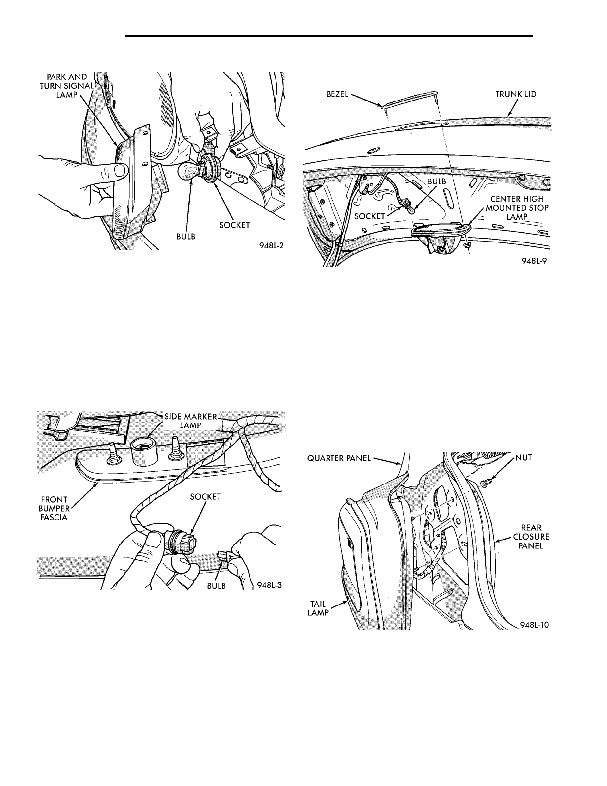
PARK AND TURN SIGNAL LAMP BULB
REMOVAL
(1) Release hood latch and open hood.
(2) Remove screws holding park and turn signal
lamp to headlamp module.
(3) Separate lamp from module.
(4) Remove bulb socket from back of lamp.
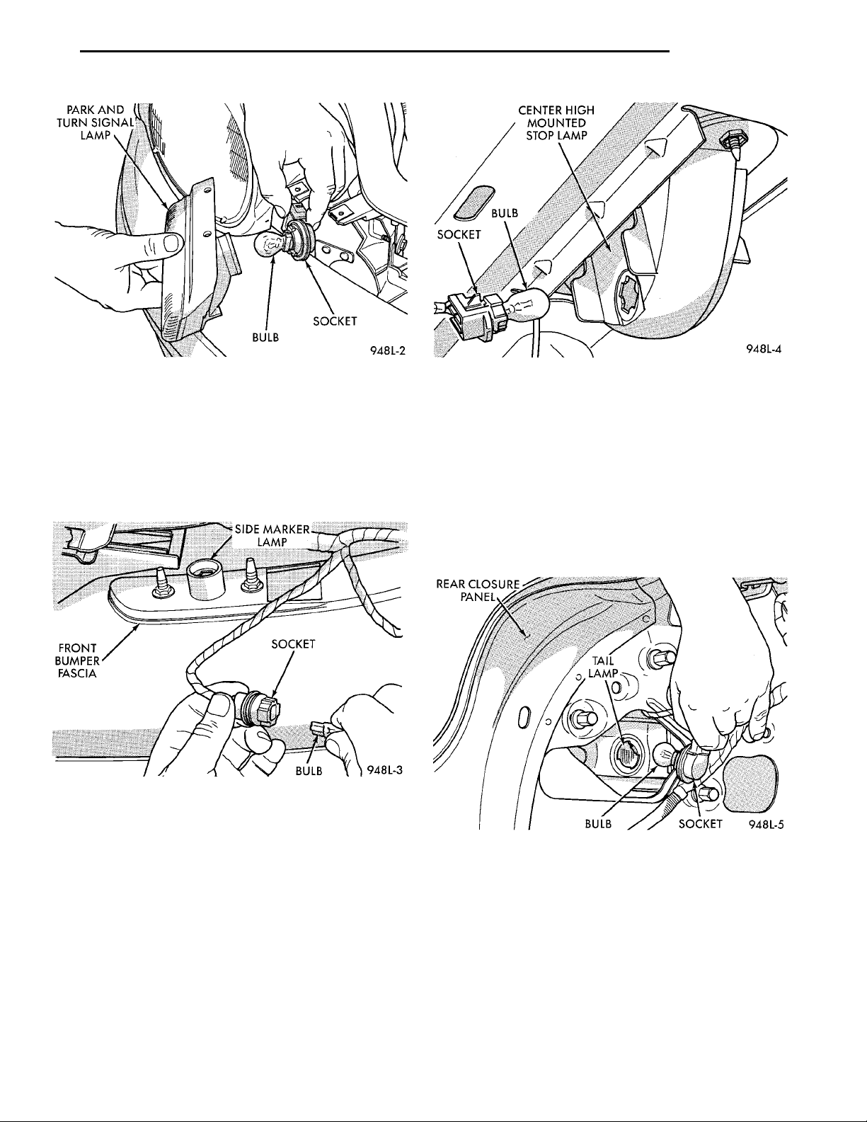
(5) Pull bulb from socket (Fig. 3).
INSTALLATION
Reverse the preceding operation.
Page 9
PARK AND TURNSIGNAL LAMP BULB SOCKET
SIDE MARKER LAMP SOCKETFRONT BUMPER FASCIABULB
REAR CLOSUREPANEL TAIL LAMP SOCKETBULB
CENTER HIGH MOUNTEDSTOP LAMPBULBSOCKET
PL LAMPS 8L - 9
REMOVAL AND INSTALLATION (Continued)
Fig. 3 Park and Turn Signal Lamp Bulb
FRONT SIDE MARKER LAMP BULB
REMOVAL
(1) Reach behind front bumper fascia forward of
front wheel.
(2) Remove socket from side marker lamp.
(3) Pull bulb from socket (Fig. 4).
Fig. 5 CHMSL Bulb
TAIL, STOP, BACK-UP AND TURN SIGNAL LAMP
BULB
REMOVAL
(1) Release trunk latch and open trunk lid.
(2) Separate trunk lining from rear closure panel
to gain access to back of tail lamp.
(3) Rotate and remove bulb socket from tail lamp
through openings in rear closure panel (Fig. 6).
(4) Pull bulb from socket.
Fig. 4 Front Side Marker
INSTALLATION
Reverse the preceding operation.
CENTER HIGH MOUNTED STOP LAMP BULB
REMOVAL
(1) Release trunk latch and open trunk lid.
(2) Remove bulb socket from center high mounted
stop lamp (Fig. 5).
(3) Pull bulb from socket.
INSTALLATION
Reverse the preceding operation.
Fig. 6 Tail and Stop Lamp Bulb
INSTALLATION
(1) Push bulb into socket.
(2) Rotate and install bulb socket into tail lamp
through openings in rear closure panel.
(3) Install trunk lining to rear closure panel.
(4) Close and secure trunk lid.
Page 10
LICENSE PLATELAMP BULB
8L - 10 LAMPS PL
REMOVAL AND INSTALLATION (Continued)
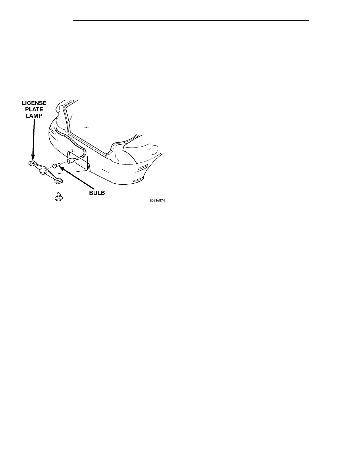
LICENSE PLATE LAMP BULB
REMOVAL
(1) Remove screws holding license plate lamp to
rear bumper (Fig. 7).
(2) Separate lamp from bumper.
(3) Remove bulb socket from lamp.
(4) Pull bulb from socket.
Fig. 7 License Plate Lamp
INSTALLATION
Reverse the preceding operation.
UNDERHOOD LAMP BULB
DOME LAMP BULB
REMOVAL
(1) Insert a trim stick between the headliner and
dome lamp lens.
(2) Carefully pry downward on the four corners of
the lamp lens.
(3) Separate lamp lens from lamp.
(4) Grasp bulb and pull from lamp socket.
INSTALLATION
(1) Position bulb in socket and snap into place.
(2) Position lens on lamp and snap into place.
VISOR VANITY LAMP BULB
REMOVAL
(1) Lower visor.
(2) Insert a small flat bladed tool between the
lamp lens and lamp.
(3) Carefully pry lens outward.
(4) Remove bulb from socket.
INSTALLATION
(1) Position bulb in socket and snap into place.
(2) Position lens on lamp and snap into place.
REAR CARGO LAMP BULB
The trunk lamp snaps into the rear shelf panel
reinforcement under/below the package shelf.
REMOVAL
(1) Disconnect the wire harness connector from the
underhood lamp.
(2) Rotate the bulb counter-clockwise. Remove it
from the lamp socket.
INSTALLATION
(1) Insert the replacement bulb in the lamp base
socket and rotate it clockwise.
(2) Connect the wire harness connector.
REMOVAL
(1) Insert a trim stick or small flat blade between
the lamp lens and rear shelf reinforcement panel.
(2) Pry the lamp lens downward.
(3) Pull bulb from socket
INSTALLATION
(1) Push bulb into socket.
(2) Position the lamp in the rear shelf reinforce-
ment panel and snap into place.
Page 11
HEADLAMP MOD-ULE UPPER CROSSMEMBERFRONT BUMPER FAS-CIA
BULB FOG LAMP
PL LAMPS 8L - 11
LAMP SERVICE
INDEX
page page
REMOVAL AND INSTALLATION
CENTER HIGH MOUNTED STOP LAMP
(CHMSL) ............................ 12
DOME LAMP .......................... 13
FOG LAMP ............................ 11
FRONT SIDE MARKER LAMP ............. 12
HEADLAMP MODULE ................... 11
REMOVAL AND INSTALLATION
HEADLAMP MODULE
REMOVAL
(1) Release hood latch and open hood.
(2) From behind bumper fascia, remove bolt hold-
ing outboard end of module to fender.
(3) Loosen bolts holding inboard end of module to
radiator closure panel.
(4) Remove bolt holding grille to headlamp module.
(5) Remove bolts holding top of module to upper
crossmember (Fig. 1).
(6) Disengage wire connector from headlamp and
parking lamp sockets.
(7) Separate headlamp module from vehicle.
LICENSE PLATE LAMP .................. 13
PARK AND TURN SIGNAL LAMP ........... 11
REAR CARGO LAMP .................... 13
TAIL, STOP AND TURN SIGNAL LAMP ...... 12
UNDERHOOD LAMP .................... 13
VISOR VANITY LAMP .................... 13
FOG LAMP
REMOVAL
(1) Remove bolt holding fog lamp to radiator clo-
sure panel (Fig. 2).
(2) Separate fog lamp from radiator closure panel.
(3) Pull fog lamp through opening in fascia.
(4) Disengage wire connector from fog lamp bulb
base.
(5) Separate fog lamp from vehicle.
Fig. 1 Headlamp Module
INSTALLATION
Reverse the preceding operation.
Fig. 2 Fog Lamp
INSTALLATION
Reverse the preceding operation.
PARK AND TURN SIGNAL LAMP
REMOVAL
(1) Release hood latch and open hood.
(2) Remove screws holding lamp to headlamp mod-
ule (Fig. 3).
(3) Separate park and turn signal lamp from vehi-
cle.
(4) Disengage wire connector from back of lamp
socket.
Page 12
PARK AND TURNSIGNAL LAMP BULB SOCKET
SIDE MARKER LAMP SOCKETBULBFRONT BUMPER FASCIA
BEZEL TRUNK LIDCENTER HIGHMOUNTED STOPLAMPSOCKET
QUARTERPANEL NUTREAR CLO-SUREPANELTAIL LAMP
BULB
8L - 12 LAMPS PL
REMOVAL AND INSTALLATION (Continued)
(5) Separate CHMSL bezel from trunk lid.
Fig. 3 Park and Turn Signal Lamp
INSTALLATION
Reverse the preceding operation.
FRONT SIDE MARKER LAMP
REMOVAL
(1) Remove socket and bulb from side marker
lamp.
(2) Remove nuts holding side marker lamp to front
bumper fascia (Fig. 4).
(3) Separate side marker lamp from vehicle.
INSTALLATION
TAIL, STOP AND TURN SIGNAL LAMP
REMOVAL
if equipped.
panel (Fig. 6).
Fig. 5 Center High Mounted Stop Lamp
Reverse the preceding operation.
(1) Release trunk latch and open trunk lid.
(2) Remove trunk trim panel from tail lamp area,
(3) Remove sockets and bulbs from lamp.
(4) Remove nuts holding tail lamp to rear closure
(5) Separate tail lamp from vehicle.
Fig. 4 Front Side Marker Lamp
INSTALLATION
Reverse the preceding operation.
CENTER HIGH MOUNTED STOP LAMP (CHMSL)
REMOVAL
(1) Release trunk latch and open trunk lid.
(2) Remove socket and bulb from lamp.
(3) Remove nuts holding center high mounted stop
lamp to trunk lid (Fig. 5).
(4) Pull CHMSL from trunk lid.
Fig. 6 Tail, Stop and Turn Signal Lamp
INSTALLATION
Reverse the preceding operation.
Page 13
LICENSE PLATELAMP BULB
PL LAMPS 8L - 13
REMOVAL AND INSTALLATION (Continued)
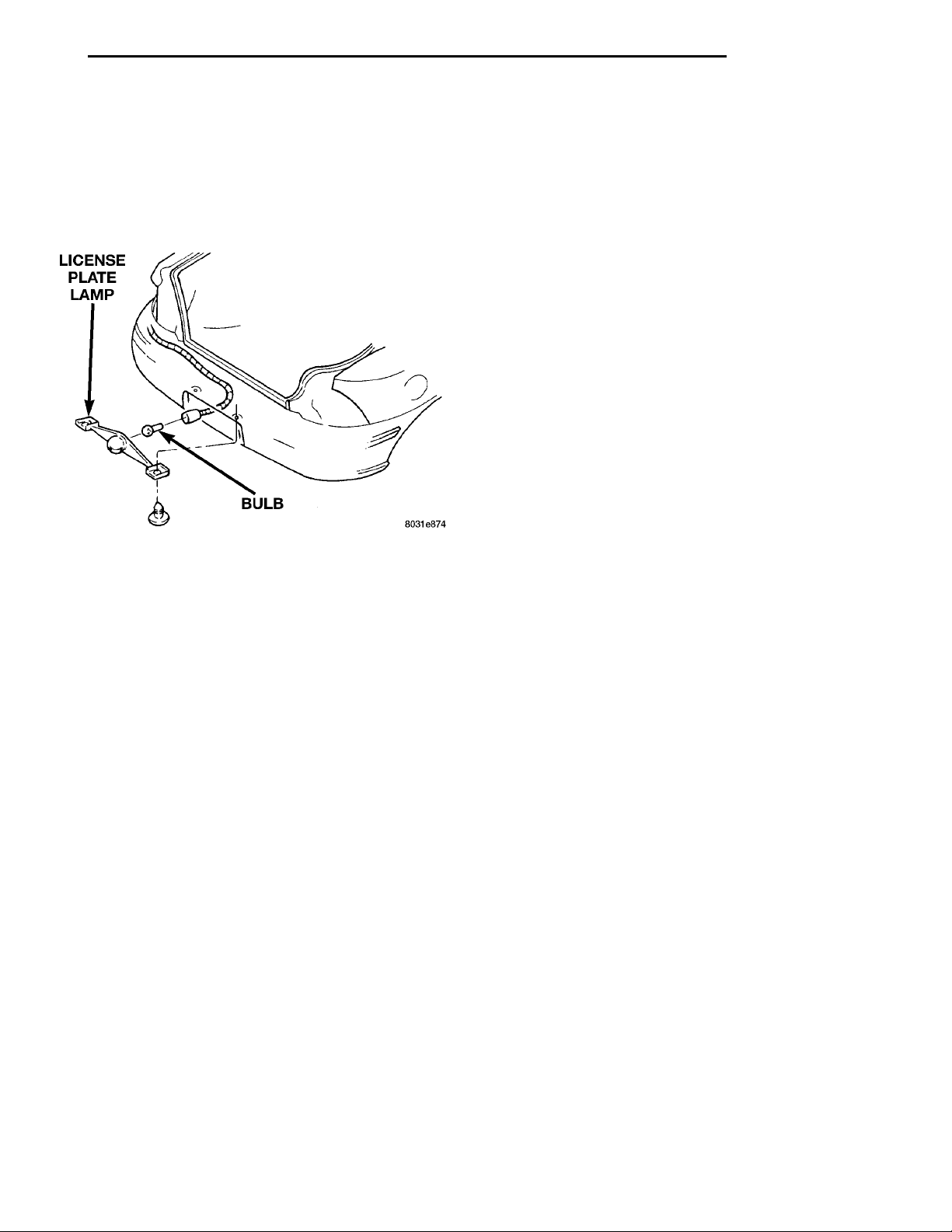
LICENSE PLATE LAMP
REMOVAL
(1) Remove screws holding license plate lamp to
rear bumper fascia (Fig. 7).
(2) Separate license plate lamp from bumper.
(3) Remove socket and bulb from lamp.
Fig. 7 License Plate Lamp
INSTALLATION
Reverse the preceding operation.
UNDERHOOD LAMP
REMOVAL
(1) Open and support hood.
(2) Remove lamp bulb.
(3) Disengage lamp wire connector.
(4) Remove the screw attaching lamp to hood.
(5) Separate lamp from vehicle.
INSTALLATION
(1) Position lamp on hood and install screw.
(2) Route lamp wire through hood silencer pad and
connect lamp wire connector.
(3) Install lamp bulb.
(4) Remove hood support and close hood.
DOME LAMP
REMOVAL
(1) Insert a trim stick between the headliner and
dome lamp lens.
(2) Carefully pry downward on the four corners of
the lamp lens.
(3) Separate lamp lens from lamp.
(4) Disengage wire connector and remove from
vehicle.
INSTALLATION
Reverse the removal procedure.
VISOR VANITY LAMP
The visor vanity lamp is incorporated in the visor
assembly. Replace the visor if the lamp has failed.
REAR CARGO LAMP
REMOVAL
(1) Insert a trim stick or small flat blade between
the lamp lens and rear shelf reinforcement panel.
(2) Pry the lamp lens downward.
(3) Disengage wire connectors.
(4) Separate lamp from vehicle.
INSTALLATION
Reverse the removal procedure.
Page 14
INSTRU-MENTPANEL CIGARLIGHTERSUPPORT BRACKETDAYTIME RUNNING LAMPMODULE
8L - 14 LAMPS PL
LAMP SYSTEMS
INDEX
page
REMOVAL AND INSTALLATION
DAYTIME RUNNING LAMP (CANADA) ....... 14
REMOVAL AND INSTALLATION
DAYTIME RUNNING LAMP (CANADA)
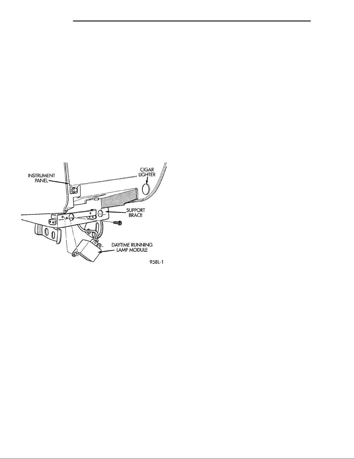
The Daytime Running Lamp module is attached to
a support brace on the underside of the instrument
panel (Fig. 1).
Fig. 1 DRL Module
REMOVAL
(1) Remove screw attaching DRL module to I/P
support brace.
(2) Disengage wire connector.
(3) Separate module from vehicle.
INSTALLATION
(1) Engage DRL module wire connector.
(2) Position module on I/P support brace and
install screw.
Page 15

PL LAMPS 8L - 15
BULB APPLICATION
INDEX
page page
SPECIFICATIONS
EXTERIOR LAMPS ..................... 15
SPECIFICATIONS
GENERAL INFORMATION
The following Bulb Application Tables lists the
lamp title on the left side of the column and trade
number or part number on the right.
CAUTION: Do not use bulbs that have a higher
candle power than the bulb listed in the Bulb Application Table. Damage to lamp can result. Do not
touch halogen bulbs with fingers or other oily surfaces. Bulb life will be reduced.
EXTERIOR LAMPS
LAMP BULB
Back-up ..............................3157
Center High Mounted Stop .................921
Fog................................GE881
Headlamp .............................9007
License Plate ...........................168
Park/Turn Signal .....................3157NA
Tail/Stop/Turn Signal ....................3157
Front Side Marker .......................168
GENERAL INFORMATION ................ 15
INTERIOR LAMPS ...................... 15
INTERIOR LAMPS
Service procedures for most of the lamps in the
instrument panel, Instrument cluster and switches
are located in Group 8E, Instrument Panel and
Gauges.
LAMP BULB
A/C and Heater Control ...................203
Ash Receiver ...........................161
Cigar Lighter ...........................203
Dome Lamp ............................578
Gear Selector Console W/Auto ..............161
Glove Compartment ......................194
Ignition Lock ...........................161
Instrument Panel and Cluster ............PC194
Rear Cargo .............................912
Underhood .............................105
Page 16

 Loading...