

Page 1

PL WINDSHIELD WIPERS AND WASHERS 8K - 1
WINDSHIELD WIPERS AND WASHERS
CONTENTS
page page
WINDSHIELD WASHER SYSTEM ............ 8 WINDSHIELD WIPERS .................... 1
WINDSHIELD WIPERS
INDEX
page page
GENERAL INFORMATION
INTRODUCTION ........................ 1
DESCRIPTION AND OPERATION
WIPER BLADES ......................... 1
DIAGNOSIS AND TESTING
WINDSHIELD WIPER CONDITION ........... 2
WIPER MOTOR ......................... 3
WIPER SWITCH ......................... 5
REMOVAL AND INSTALLATION
WIPER ARM ........................... 5
GENERAL INFORMATION
INTRODUCTION
WARNING: VEHICLES ARE EQUIPPED WITH AN
AIRBAG, REFER TO GROUP 8M, RESTRAINT SYSTEMS FOR STEERING WHEEL OR COLUMN SERVICE PROCEDURES.
The windshield wipers will only operate with the
ignition switch in the ACCESSORY or IGNITION
RUN position. The wiper circuit is protect against
over loads by a fuse in the fuse block and a circuit
breaker within the wiper motor. This protects the circuitry of the wiper system and the vehicle.
The wiper motor has permanent magnet fields.
The intermittent wiper system, in addition to low
and high speed, has a delay mode and a pulse wipe
mode. The delay mode has a range of 1 to 15 seconds.
Pulse wipe is accomplished by momentarily moving
the stalk lever into the WASH position while the
wiper switch is in either OFF or DELAY position.
The wiper blades then sweep once or twice and
return to the previous wiper switch mode, OFF or
DELAY.
WIPER BLADE ELEMENT ................. 5
WIPER BLADE .......................... 5
WIPER LINKAGE ........................ 6
WIPER MODULE ........................ 6
WIPER MOTOR ......................... 6
WIPER SWITCH ......................... 6
CLEANING AND INSPECTION
WIPER BLADES ......................... 7
ADJUSTMENTS
WIPER ARM ADJUSTMENT ................ 7
The intermittent wiper function is integral to the
wiper switch. All electronics and relay are inside the
switch assembly.
The wiper system completes the wipe cycle when
the switch is turned OFF. The blades park in the
lowest portion of the wipe pattern.
NOTE: This group covers both Left-Hand Drive
(LHD) and Right-Hand Drive (RHD) versions of this
model. Whenever required and feasible, the RHD
versions of affected vehicle components have been
constructed as mirror-image of the LHD versions.
While most of the illustrations used in this group
represent only the LHD version, the diagnostic and
service procedures outlined can generally be
applied to either version. Exceptions to this rule
have been clearly identified as LHD, RHD, or Export
if a special illustration or procedure is required.
DESCRIPTION AND OPERATION
WIPER BLADES
Wiper blades, exposed to the weather for a long
period of time, tend to lose their wiping effectiveness.
Periodic cleaning of the wiper blade is suggested to
Page 2
FUSE 15 WIPER COMBO FLASHERTIME DELAY RELAY
CAV FUNCTIONHILOPARK
IGNITION FEED
8K - 2 WINDSHIELD WIPERS AND WASHERS PL
DESCRIPTION AND OPERATION (Continued)
remove the accumulation of salt and road film. The
wiper blades, arms, and windshield should be
cleaned with a sponge or cloth and a mild detergent
or nonabrasive cleaner. If the blades continue to
streak or smear, they should be replaced. The right
and left wipers are different blade lengths. The
driver side length is 525 mm and the passenger side
length is 450 mm. The blades should not be interchanged.
DIAGNOSIS AND TESTING
WINDSHIELD WIPER CONDITION
WARNING: ON VEHICLES EQUIPPED WITH AIRBAGS, SEE GROUP 8M, RESTRAINT SYSTEMS FOR
STEERING WHEEL OR COLUMN REMOVAL PROCEDURES.
The following is a list of general wiper motor system problems, the tests that are to be performed to
locate the faulty part, and the corrective action to be
taken.
Whatever the problem, disconnect motor wire harness and clean the terminals, then connect motor
wire harness and test.
MOTOR WILL NOT OPERATE IN SOME OR ALL SWITCH POSITIONS
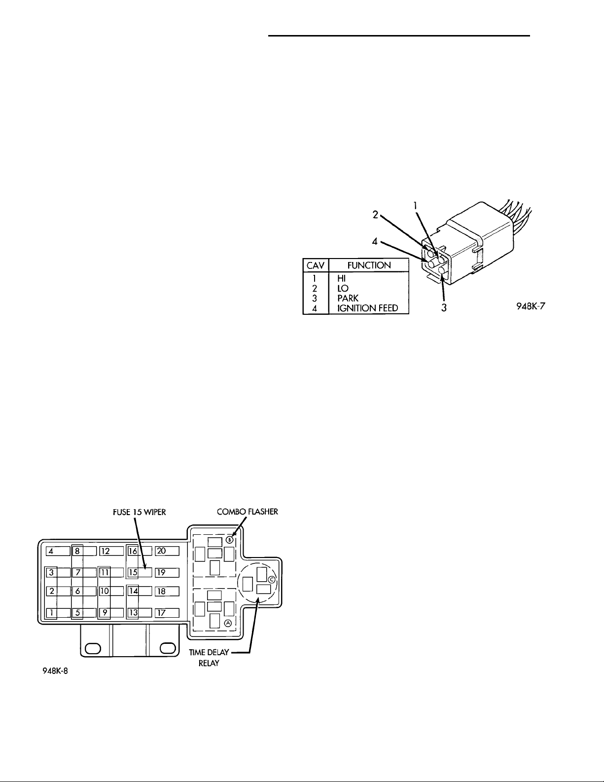
(1) Check fuse 15, in the fuse block (Fig. 1).
(a) If fuse is OK, go to Step 2.
(b) If fuse is defective, replace and check motor
operation in all switch positions.
(c) If motor is still inoperative and the fuse does
not blow, go to Step 2.
(d) If replacement fuse blows, go to Step 6.
positive terminal and terminal 2 of the motor connector. Connect the other jumper wire to the battery
negative terminal and the motor ground strap (Fig.
2). Check motor high speed, connect the positive
jumper wire to terminal 1 of the motor connector.
Connect the negative jumper wire to the motor
ground strap.
(a) If motor does not run, high or low speed go to
Step 4.
(b) If motor runs, go to Step 5.
Fig. 2 Motor Connector
(4) Using an ohmmeter, check for good ground at
the motor ground strap. If OK, replace motor. If not
repair the ground circuit as necessary.
(5) Check terminal E of wiper switch connector for
continuity to ground. If OK, go to Step 6. If not OK,
repair the ground circuit as necessary.
(6) Using a voltmeter, with wiper switch connected, connect negative lead to motor ground strap.
Connect the positive lead to terminal P1 of the wiper
switch connector (Fig. 3) and (Fig. 5).
(a) If no voltage, repair wiring as necessary. If
OK, go to Step 2.
(b) Check wiper switch low speed, connect voltmeter positive lead to terminal L of the wiper
switch connector. Move wiper stalk to LOW position. If no voltage, replace switch.
(c) Check wiper switch high speed, connect voltmeter positive lead to terminal H of the wiper
switch connector. Move wiper stalk to HIGH position. If no voltage, replace switch.
(7) Disconnect motor connector and replace fuse 15
in fuse block.
(a) If fuse does not blow, replace motor.
(b) If fuse blows, disconnect wiper switch and
replace fuse.
(c) If fuse does not blow, replace switch.
(d) If fuse blows, repair wiring as necessary.
Fig. 1 Fuse Block
(2) Disconnect motor wire connector.
(3) Check motor low speed. Using two jumper
wires, connect one jumper wire between the battery
MOTOR OPERATES SLOWLY AT ALL SPEEDS
(1) Remove wiper arms and cowl screen. Discon-
nect motor linkage from motor. Connect an ammeter
between battery positive terminal and terminal 4 of
Page 3
TERMINAL 4 AMMETER+ BATTERY —
PL WINDSHIELD WIPERS AND WASHERS 8K - 3
DIAGNOSIS AND TESTING (Continued)
(2) Using an ohmmeter, check the high and low
circuits for a short to ground. Refer to Group 8W,
Wiring Diagrams.
(3) Check to see if wiper linkage or pivots are
binding or caught.
WIPERS RUN AT HIGH SPEED WITH SWITCH IN LOW SPEED POSITION OR WIPERS RUN AT LOW SPEED WITH SWITCH IN HIGH SPEED POSITION.
(1) Check for crossed wires in the motor pigtail
wire connector. Refer to Group 8W, Wiring Diagrams.
(2) Check for crossed wires in harness connector
from wiper switch to motor.
(3) If OK, replace wiper switch.
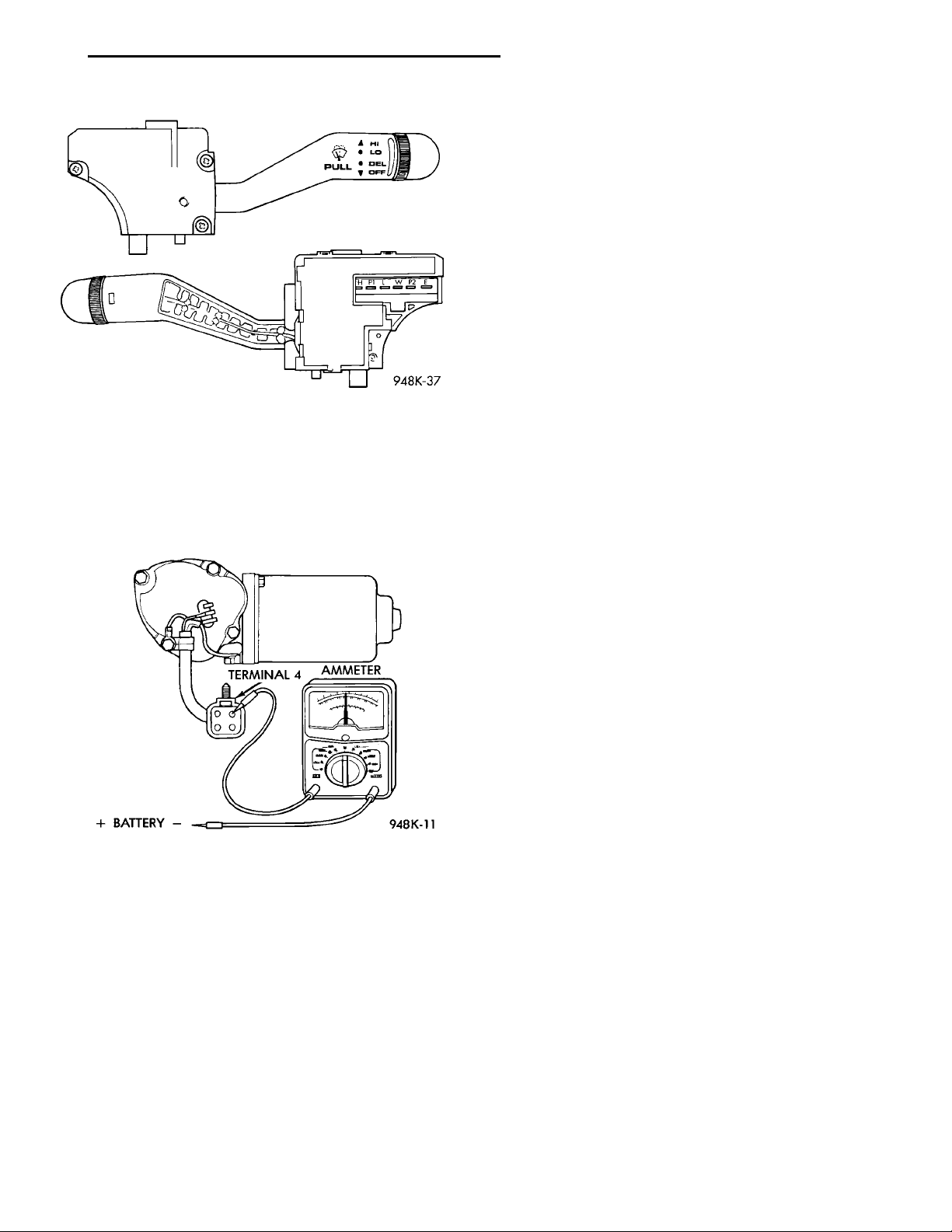
Fig. 3 Wiper Switch and Terminals
the motor connector (Fig. 4). Turn wiper motor on
and check ampere reading.
If motor runs and ammeter reading is more than 6
amps, go to Step 2. If less than 6 amps, go to Step 3.
When replacing drive link nut tighten to 11 to 12
N·m (98 to 106 in. lbs.) torque.
Fig. 4 Ammeter Test
WIPERS WILL OPERATE CONTINUOUSLY WITH SWITCH IN THE INTERMITTENT POSITION—WHEN WIPER SWITCH IS TURNED OFF, WIPERS STOP WHEREVER THEY ARE, WITHOUT RETURNING TO PARK POSITION.
(1) Check at motor ground strap for a good ground.
(2) Turn ignition switch OFF. Using an ohmmeter,
with the motor in the park position, check for continuity between terminal 3 and ground strap. If continuity, replace wiper switch. If no continuity, repair
wiring as necessary.
WIPERS DO NOT OPERATE WHEN WASHER MOTOR IS ENGAGED (PULSE WIPE) OR WIPERS DO OPERATE IN INTERMITTENT POSITION.
Check for a good ground at motor ground strap and
at wiper switch terminal E. If OK, replace wiper
switch. If not OK, repair wiring as necessary.
WIPER MOTOR
WARNING: ON VEHICLES EQUIPPED WITH AIRBAGS, SEE GROUP 8M, RESTRAINT SYSTEMS FOR
STEERING WHEEL OR COLUMN REMOVAL PROCEDURES.
Whenever a wiper motor malfunction occurs, verify
that the wire harness is properly connected start normal diagnosis and repair procedures. Refer to Wiper
Motor Test.
Page 4

8K - 4 WINDSHIELD WIPERS AND WASHERS PL
DIAGNOSIS AND TESTING (Continued)
CONDITION POSSIBLE CAUSES CORRECTION
Wiper blades do not park properly. (1) Wiper arms improperly parked.
(2) Wiper arms are loose on pivot
shaft.
(3) Motor crank loose at output
shaft.
Motor stops in any position when
the switch is turned off.
Motor will not stop when the switch
is turned off.
Wiper blades slap against cowl
screen or window moldings.
Blades chatter. (1) Foreign substance such as
Wiper knock at reversal. (1) Linkage bushings worn.
Wiper motor will not run. (1) Blown fuse.
(1) Open park circuit. (1) Check park switch by
(1) Faulty switch.
(2) Lock of dynamic brake on wet
glass.
(1) Wiper arms are parked
incorrectly.
polish on glass or blades.
(2) Arms twisted, blade at wrong
angle on glass.
(3) Blade structure bent.
(4) Blade element has permanent
set.
(2) Armature endplay in motor.
(2) New fuse blows.
(3) New fuse blows.
(4) No Voltage at motor.
(5) Poor ground.
(1) Remove wiper arms and repark.
Refer to Wiper Arm Removal and
Installation.
(2) Remove wiper arm and repark.
Refer to Wiper Arm Removal and
Installation.
(3) Remove wiper arm, run wiper
motor to park position and remove
the module. Without rotating the
motor output shaft, remove the crank
and clean any foreign matter from
the motor shaft. Install the motor
crank in its original position.
disconnecting the wire connector
and apply battery voltage to Pin 4.
Place a jumper wire from Pin 2 to
Pin 3 and then to an external
ground. Replace motor if it does not
park.
(1) check switch in low, high and
intermittent position.
(2) Ensure park switch has clean
ground.
(1) Park wiper arms. Refer to Wiper
Arm Adjustment.
(1) Clean glass and blade element
with non-abrasive cleaner.
(2) Replace arm.
(3) Replace blade.
(4) Replace blade element.
(1) Replace worn link. Refer to
Wiper Linkage Removal and
Installation.
(2) Replace wiper motor. Refer to
Wiper Motor Removal and
Installation.
(1) Replace fuse, and run system.
(2) Check for short in wiring or
switch.
(3) Replace fuse, remove motor
connector, turn switch ON, fuse does
not blow, replace motor.
(4) Check switch and wiring harness.
Refer to Group 8W, Wiring
Diagrams.
(5) Repair ground wire connection as
necessary.
Page 5
INTERMITTENT WIPERSWITCH PINS
PL WINDSHIELD WIPERS AND WASHERS 8K - 5
DIAGNOSIS AND TESTING (Continued)
WIPER SWITCH
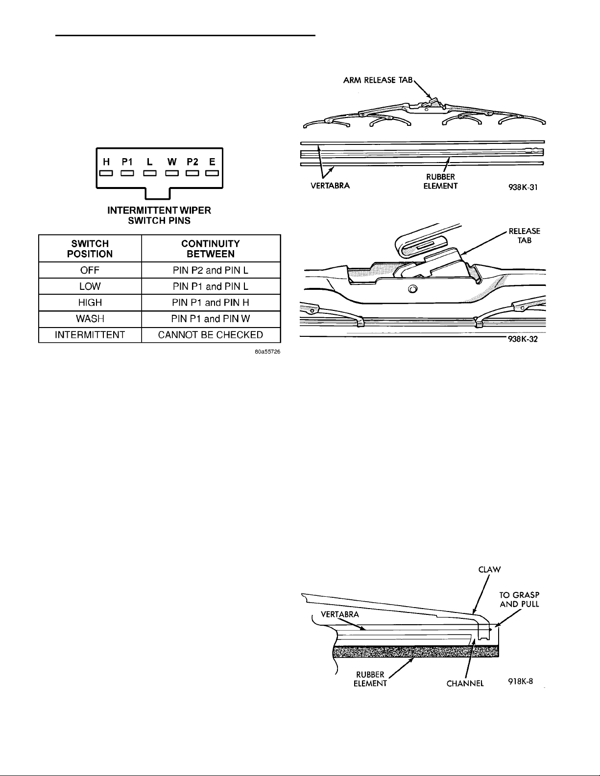
To test the switch, first disconnect the switch wires
from the body wiring in the steering column. Using
an ohmmeter, test for continuity between the terminals of the switch, as indicated in the following continuity chart (Fig. 5).
Fig. 6 Wiper Blade and Element
Fig. 5 Wiper Switch Test
REMOVAL AND INSTALLATION
WIPER ARM
REMOVAL
(1) Place the wiper arm/blades in the PARK position and turn ignition OFF.
(2) Remove arm cap and wiper arm nut.
(3) Remove the arm from the pivot using a rocking
motion.
(4) Clean metal splinters OFF the pivot shafts.
INSTALLATION
For installation reverse above procedures. Before
installation activate wiper system to ensure the
wiper module is in the PARK position. Position wiper
arms so that the heel of the blade(s) is on the park
line on the windshield.
WIPER BLADE
REMOVAL
(1) Lift wiper arm to over center position.
(2) Remove blade assembly from arm by pushing
release tab under arm tip and slide blade away from
arm tip (Fig. 6) and (Fig. 7).
(3) Gently place wiper arm tip on glass surface.
Fig. 7 Remove Blade from Arm
WIPER BLADE ELEMENT
REMOVAL
(1) Lift wiper arm to raise blade off glass.
(2) Remove blade assembly from arm by pushing
release tab under arm tip and slide blade away from
arm tip (Fig. 6) and (Fig. 7). Gently place wiper arm
tip on glass surface.
(3) Remove wiping element from blade assembly.
Pull stopper, of the rubber element, out of the end
claw together with vertibra (metal rails) (Fig. 8).
VERTABRA
INSTALLATION
For installation reverse the above procedures.
Check that the element and vertibra are through all
claws and the final claw is locked in the stopper.
CLAWTO GRASP ANDPULLCHANNELRUBBER ELEMENT
INSTALLATION
For installation reverse above procedures.
Fig. 8 Wiper Blade and Element
Page 6
8K - 6 WINDSHIELD WIPERS AND WASHERS PL
REMOVAL AND INSTALLATION (Continued)
WIPER LINKAGE
REMOVAL
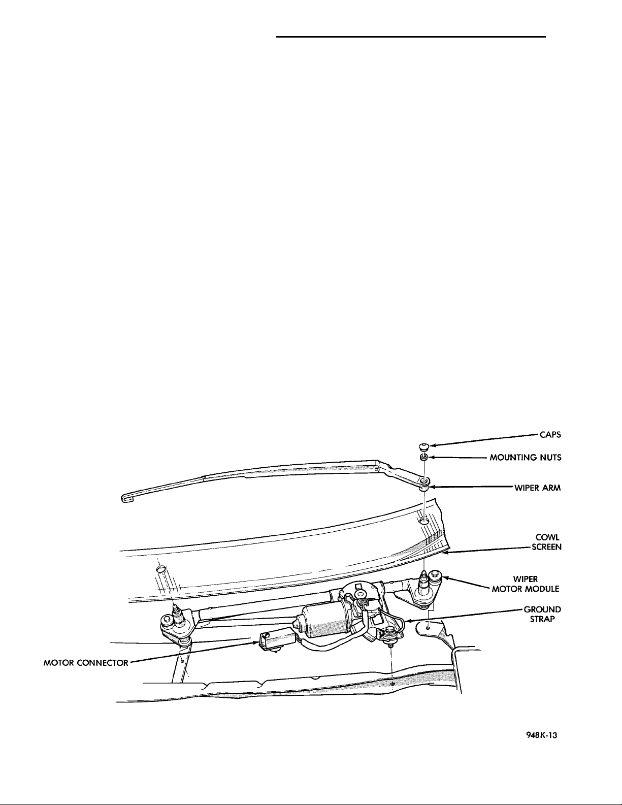
(1) Remove wiper module refer above (Fig. 9).
(2) Disconnect wiper arm linkage, by insert screwdriver between ball cap and linkage, then twist the
screwdriver and lift straight up on linkage.
INSTALLATION
For installation reverse the above procedures.
Using pliers or hand press the ball cap straight on to
the ball stud.
WIPER MODULE
REMOVAL
(1) Remove wiper arms and blades (Fig. 9).
(2) Remove the rear hood seal with the cowl top
plastic screen.
(3) Disconnect motor wire connector at front plenum wall.
(4) Remove wiper module mounting screws and
remove module.
INSTALLATION
For installation reverse the above procedures.
Tighten the mounting screws to 7 to 9 N·m (60 to 80
in. lbs.) torque.
WIPER MOTOR
REMOVAL
(1) Remove wiper module refer above.
(2) Remove linkage from motor crank. Insert
screwdriver between crank and linkage then twist
the screwdriver and lift straight up on linkage.
(3) Remove motor mounting screws and remove
motor.
INSTALLATION
For installation add unilube grease to socket and
reverse the above procedures. Tighten the motor
mounting screws to 5 to 6 N·m (45 to 55 in. lbs.)
torque. Tighten drive link nut to 11 to 12 N·m (98 to
106 in. lbs.) torque.
WIPER SWITCH
REMOVAL
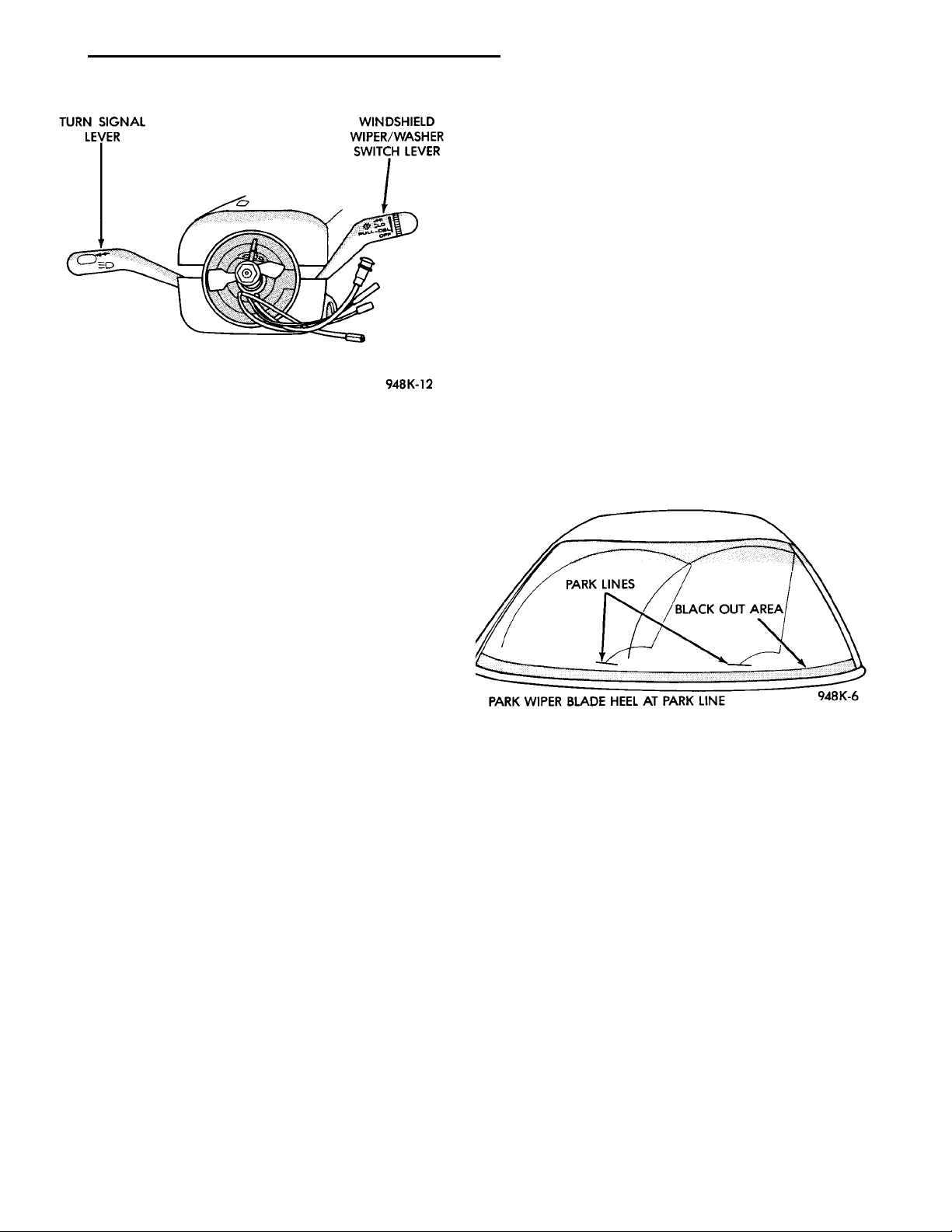
(1) Remove three screws holding steering column
shroud and remove upper half of shroud (Fig. 10).
(2) Remove mounting screw on switch and remove
switch.
(3) Disconnect wire harness connector from switch.
INSTALLATION
For installation, reverse the above procedures.
CAPSMOUNTINGNUTSWIPERARMCOWLSCREENWIPER MOTOR MOD-ULEGROUNDSTRAPMOTOR CONNECTOR
Fig. 9 Wiper Motor and Linkage Module
Page 7
TURN SIGNAL LEVER WINDSHIELD WIPER/WASHER SWITCHLEVER
PL WINDSHIELD WIPERS AND WASHERS 8K - 7
shield. If the wiper blades are new and the wiper
arm spring tension is OK and a chattering sound is
emitted from the wiper(s), the wiper blade is not rolling over center. If this condition exists, refer to the
Wiper Arm Alignment paragraph of this group.
ADJUSTMENTS
WIPER ARM ADJUSTMENT
(1) Cycle the wiper motor into the PARK position.
(2) Lift the wiper blade off the windshield and
release it.
(3) The wiper blade heel should be parked within 5
mm of the park line. The park line is mark on the
Fig. 10 Upper Shroud Removal
CLEANING AND INSPECTION
WIPER BLADES
Wiper blades exposed to the weather for a long
period of time tend to lose their wiping effectiveness.
Periodic cleaning of the wiper blade is recommended
to remove the accumulation of salt and road grime.
The wiper blades, arms and windshield should be
cleaned with a sponge or cloth and a mild detergent
or nonabrasive cleaner. If the wiper blades continue
to streak or smear, they should be replaced. The
wiper blade should run smoothly across the windshield in both directions. The wiper blade should
slightly roll over center when the blade reverses
direction. A wiper blade insert that has lost flexibility
or a wiper arm that has lost spring tension, will
cause the blade to skip or chatter across the wind-
windshield (Fig. 11).
(4) In the event that the wiper blade tip excessively strikes the cowl screen due to long term normal wear, reposition the wiper blade heel slightly
above the park line. Make sure that the wipers are
in the PARK position.
PARK LINES BLACK OUT AREAPARK WIPER BLADE HEEL AT PARK LINE
Fig. 11 Arm Adjustment
Page 8
HOOD ADJUST WITH A PINFWDNOZZLE
NOZZLE AIRTARGET
8K - 8 WINDSHIELD WIPERS AND WASHERS PL
WINDSHIELD WASHER SYSTEM
INDEX
page page
DESCRIPTION AND OPERATION
WASHER NOZZLE ....................... 8
DIAGNOSIS AND TESTING
WINDSHIELD WASHERS .................. 8
DESCRIPTION AND OPERATION
WASHER NOZZLE
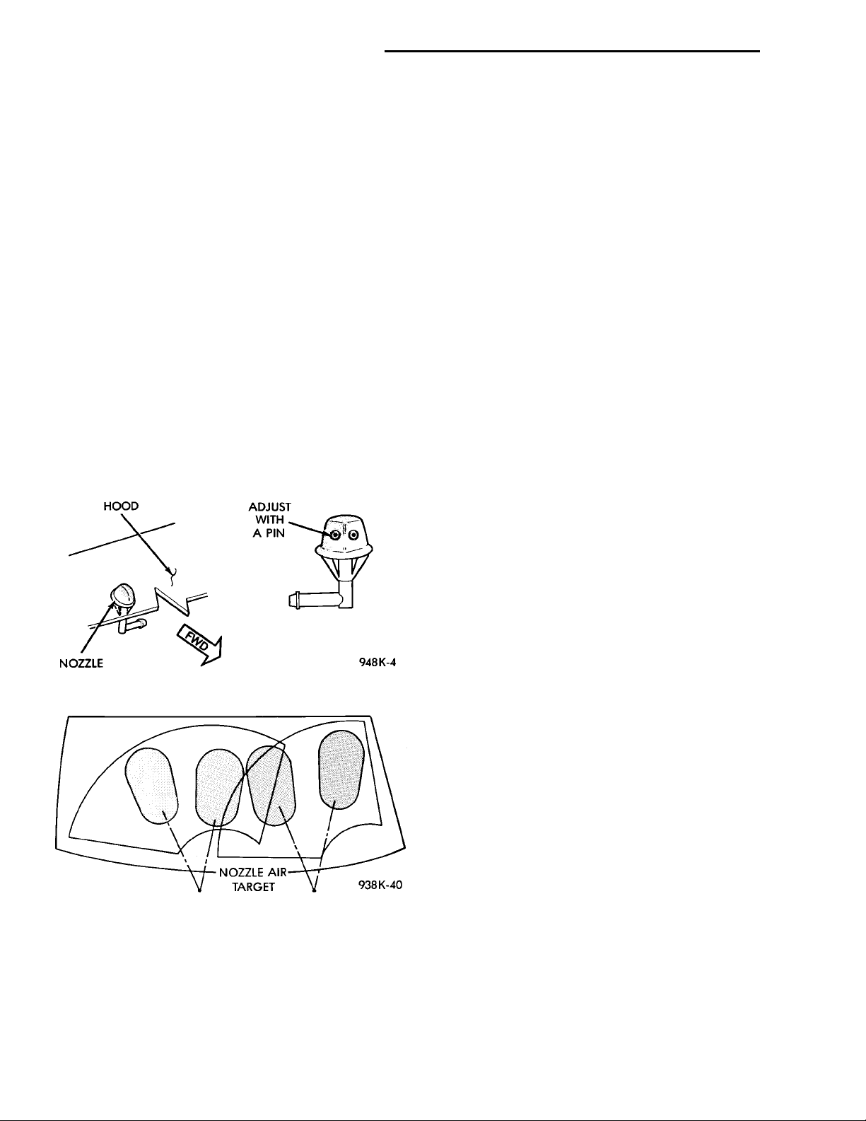
This model is equipped with two hood mounted
washer nozzles. Each nozzle emits two streams into
the wiper pattern (Fig. 1). If the nozzle performance
is unsatisfactory they can be adjusted. To adjust
insert a pin into the nozzle ball and move to proper
pattern (Fig. 2). The right and left nozzles are identical.
Fig. 1 Windshield Washer Nozzle
REMOVAL AND INSTALLATION
WASHER NOZZLE ....................... 8
WASHER RESERVOIR PUMP ............. 10
WASHER RESERVOIR .................... 9
DIAGNOSIS AND TESTING
WINDSHIELD WASHERS
All models are equipped with electric operated
windshield washer pumps.
The wash function can be accessed in the OFF
position of the wiper control switch. Holding the
wash button depressed when the switch is in the
OFF position will operate the wipers and washer
motor pump continuously until the washer button is
released. Releasing the button will stop the washer
pump but the wipers will complete the current wipe
cycle. Followed by an average of two more wipe
cycles (61) before the wipers park and the module
turns off.
Whenever a windshield washer malfunction occurs,
first verify that the windshield washer wire harness
is properly connected to all connectors before starting
normal diagnosis and repair procedures. Refer to
Windshield Washer Test (Fig. 3).
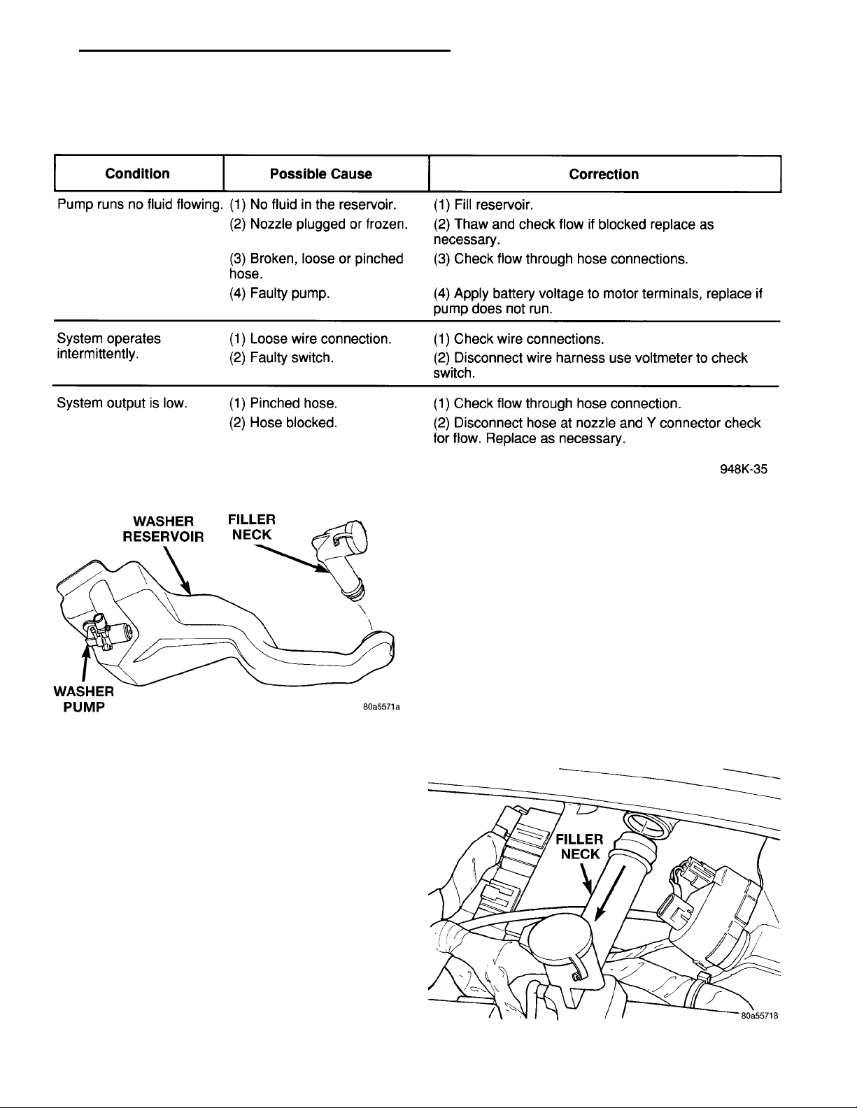
The electric pump assembly is mounted directly to
the reservoir. A permanently lubricated motor is coupled to a rotor type pump. Fluid, gravity fed from the
reservoir, is forced by the pump through rubber hoses
to the hood mounted nozzles which direct the fluid
streams to the windshield.
The pump and reservoir are serviced as separate
assemblies (Fig. 4).
Fig. 2 Windshield Washer Pattern
Page 9
WASHER PUMPWASHER RESERVOIRFILLER NECK
PL WINDSHIELD WIPERS AND WASHERS 8K - 9
FILLER NECK
Fig. 3 Windshield Washer Test
Fig. 4 Washer Fluid Reservoir
REMOVAL AND INSTALLATION
WASHER NOZZLE
REMOVAL
(1) Disconnect washer fluid hose at the nozzle.
(2) Using a needle nose pliers, squeeze together
the locking tabs on the nozzle (Fig. 1).
(3) Remove nozzle.
WASHER RESERVOIR
REMOVAL
(1) Remove filler neck (Fig. 5).
(2) Raise vehicle on hoist.
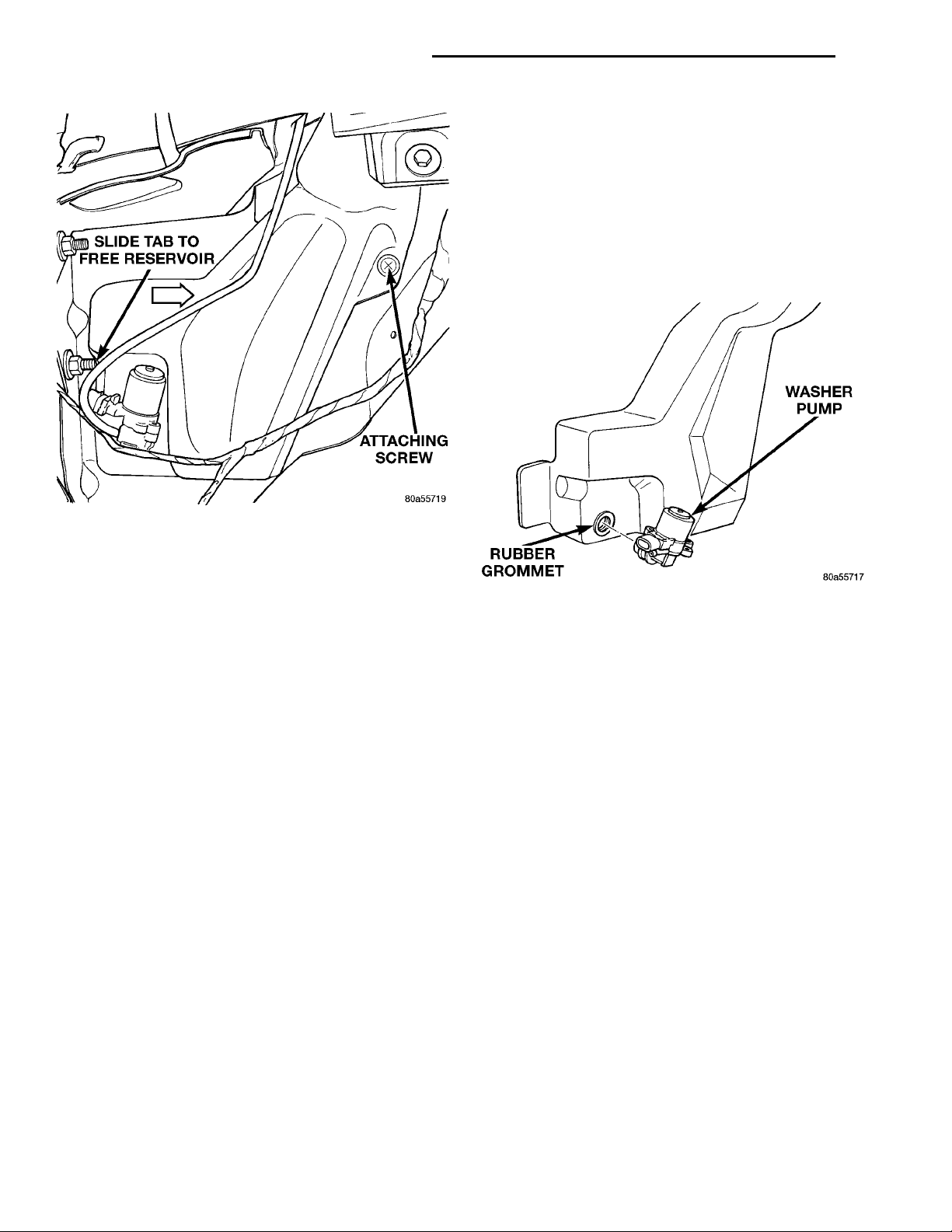
(3) Disconnect the wire connector from the reservoir pump (Fig. 6).
(4) Disconnect the washer hose at the pump and
drain the reservoir.
(5) Remove fastener from reservoir.
(6) Remove the reservoir through fender opening.
INSTALLATION
For installation, reverse the above procedures.
Tighten the reservoir screw to 2.2 to 3.3 N·m (20 to
29 in. lbs.) torque.
INSTALLATION
(1) Place the nozzle in position and push downward till locking tabs are securely snapped into position.
(2) Connect the washer hose and ensure that the
hose is not kinked.
Fig. 5 Filler Neck Removal
Page 10
SLIDE TAB TO FREE RESER-VOIRATTACHING SCREW
8K - 10 WINDSHIELD WIPERS AND WASHERS PL
REMOVAL AND INSTALLATION (Continued)
(3) Disconnect the washer hose at the pump and
drain the reservoir.
(4) Gently pry pump away from reservoir and out
of grommet. Care must be taken not to puncture reservoir (Fig. 7).
(5) Remover rubber grommet from reservoir and
throw away.
INSTALLATION
For installation, reverse the above procedures.
Fig. 6 Reservoir Removal
WASHER RESERVOIR PUMP
REMOVAL
(1) Raise vehicle on hoist.
(2) Disconnect the wire connector from the reser-
voir pump.
Fig. 7 Washer Pump
 Loading...