

Page 1
COMBO FLASHERTIME DELAYRELAY
PL TURN SIGNAL AND FLASHERS 8J - 1
TURN SIGNAL AND FLASHERS
CONTENTS
page page
GENERAL INFORMATION
INTRODUCTION ........................ 1
DESCRIPTION AND OPERATION
COMBINATION FLASHER ................. 1
HAZARD WARNING SYSTEM .............. 1
GENERAL INFORMATION
INTRODUCTION
WARNING: ON VEHICLES EQUIPPED WITH AIRBAG, SEE GROUP 8M, RESTRAINT SYSTEMS FOR
AIRBAG REMOVAL PROCEDURES.
The turn signals are part of the multi-function
switch. Which contains:
• Electrical circuitry for turn signals
• Hazard warning switch
• Headlamp beam select switch
• Headlamp optical horn
The integrated switch assembly is mounted to the
left hand side of the steering column. When the
driver wishes to signal his intentions to change direction of travel, he moves the lever upward to cause
the right signals to flash and downward to cause the
left signals to flash. After completion of a turn the
system is deactivated automatically. As the steering
wheel returns to the straight ahead position, a canceling cam molded to the clockspring mechanism
comes in contact with the cancel actuator on the turn
signal multi-function switch assembly. The cam lobe,
pushing on the cancel actuator, returns the switch to
the off position.
If only momentary signaling such as indication of a
lane change is desired, the switch is actuated to a
left or right intermediate detent position. In this
position the signal lamps flash as described above,
but the switch returns to the OFF position as soon as
the lever is released.
When the system is activated, one of two indicator
lamps mounted in the instrument cluster flashes in
unison with the turn signal lamps, indicating to the
driver that the system is operating.
DIAGNOSIS AND TESTING
MULTI-FUNCTION SWITCH ................ 2
REMOVAL AND INSTALLATION
MULTI-FUNCTION SWITCH ................ 3
While most of the illustrations used in this group
represent only the LHD version, the diagnostic and
service procedures outlined can generally be
applied to either version. Exceptions to this rule
have been clearly identified as LHD, RHD, or Export
if a special illustration or procedure is required.
DESCRIPTION AND OPERATION
HAZARD WARNING SYSTEM
The hazard warning system is actuated by a slide
button located on the top of the steering column
between the steering wheel and the instrument
panel. The hazard switch is identified with a double
triangle on front of the button.
COMBINATION FLASHER
The turn signal flasher and the hazard warning
flasher are combined into one unit called a combination flasher (combo-flasher). The combo- flasher controls the flashing of the hazard warning system and
the turn signal system. An inoperative bulb or incomplete turn signal circuit will cause the flasher rate to
double.
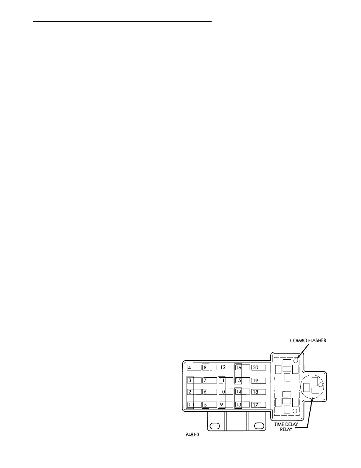
The combo-flasher is located on the fuse block. The
combo-flasher is black in color for ease of identification (Fig. 1).
NOTE: This group covers both Left-Hand Drive
(LHD) and Right-Hand Drive (RHD) versions of this
model. Whenever required and feasible, the RHD
versions of affected vehicle components have been
constructed as mirror-image of the LHD versions.
Fig. 1 Combo-Flasher
Page 2

8J - 2 TURN SIGNAL AND FLASHERS PL
DIAGNOSIS AND TESTING
MULTI-FUNCTION SWITCH
The multi-function switch contains electrical circuitry for turn signal, hazard warning, headlamp
beam select, headlamp optical horn. This integrated
switch assembly is mounted to the left hand side of
the steering column. Should any function of the
switch fail, the entire switch assembly must be
replaced. Refer to Turn Signal and Hazard Warning
Flasher Diagnosis Chart for diagnosis.
MULTI-FUNCTION SWITCH TEST
CONDITION POSSIBLE CAUSES CORRECTION
Turn signal flashes at twice the
normal rate.
Indicator lamp illuminated brightly,
external lamp glows dimly at a
rapid rate.
Hazard warming system does not
flash.
Indicator lamp illuminates brightly,
external lamp does not light.
System does not flash on either
side.
System does not cancel after
completion of the turn.
External lamps operate properly,
no indicator lamp operation.
(1) Faulty external lamp.
(2) Poor ground at lamp.
(3) Open circuit in wiring to external
lamp.
(4) Faulty contact in switch.
(1) Loose or corroded external lamp
connection.
(2) Poor ground circuit at external
lamp.
(1) Faulty fuse.
(2) Faulty flasher.
(3) Open circuit in feed wire to
switch.
(4) faulty contact in switch.
(5) Open or grounded circuit in
wiring to external lamps.
(1) Open circuit in wire to external
lamp.
(2) Burned out lamp.
(1) Faulty fuse.
(2) Faulty flasher unit.
(3) Loose bulkhead connector.
(4) Loose or faulty rear wiring
harness or terminals.
(5) Open circuit to flasher unit.
(6) Open circuit in feed wire to turn
signal switch.
(7) Faulty switch connection in
switch.
(8) Open or grounded circuit in
wiring to external lamps.
(1) Broken cancelling finger on
switch.
(2) Broken or missing cancelling
cam on clockspring.
(1) Faulty indicator lamp in
instrument cluster.
(1) Replace lamp.
(2) Check and/or repair wiring
(3) Repair wiring harness. Check
connectors.
(4) Replace multi function switch.
(1) Replace socket connection.
(2) Repair wiring harness. Check
connectors.
(1) Replace fuse.
(2) Replace flasher.
(3) Repair wiring harness, Check
connectors.
(4) Replace multi function switch.
(5) Repair wiring harness.
(1) Repair wiring harness.
(2) Replace lamp.
(1) Replace fuse.
(2) Replace flasher.
(3) Tighten connector.
(4) Repair wiring harness
(5) Check connectors, repair wiring
harness.
(6) Check connectors, repair wiring
harness.
(7) Replace multi function switch.
(8) Repair wiring harness.
(1) Replace multi function switch.
(2) Replace clockspring.
(1) Replace lamp.
Page 3
H — RIGHT REARI — LEFT FRONTJ — RIGHT FRONTK — LEFT REAR
PL TURN SIGNAL AND FLASHERS 8J - 3
DIAGNOSIS AND TESTING (Continued)
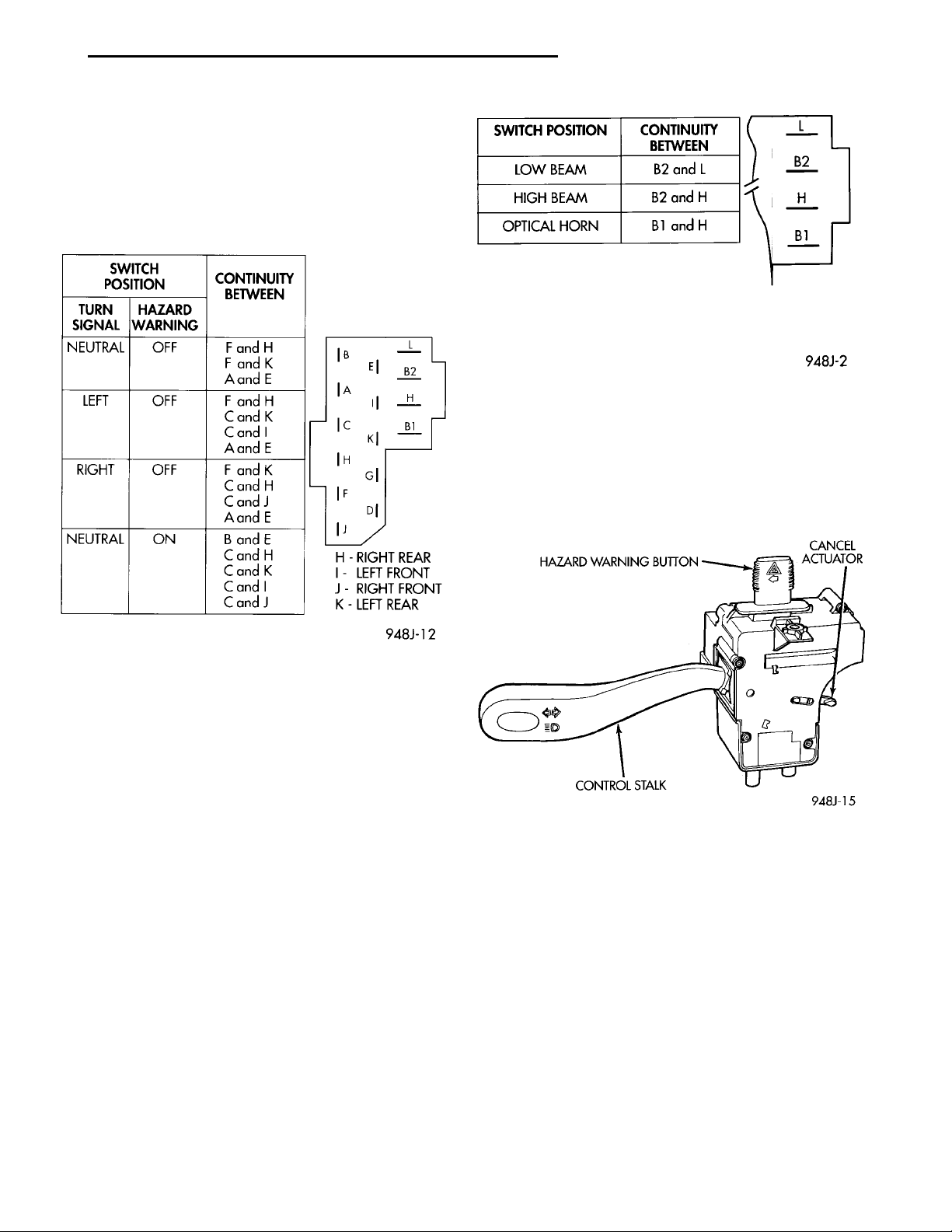
To test the switch, first disconnect the negative
battery cable, then remove the upper and lower column shrouds to gain access to the switch connector.
Remove switch connector. Using an ohmmeter, test
for continuity (no resistance) between the terminals
of the switch as shown in the following continuity
charts (Fig. 2) and (Fig. 3).
HAZARD WARNING BUTTON CANCELACTUATORCONTROL STALK
Fig. 3 Beam Select Switch Continuity
INSTALLATION
For installation, reverse the above procedures.
• Tighten multi-function switch to column retain-
ing screws to 2 N·m (17 in. lbs.) torque.
• Tighten steering column cover retaining screws
to 2 N·m (17 in. lbs.) torque.
Fig. 2 Turn Signal and Hazard Switch Continuity
REMOVAL AND INSTALLATION
MULTI-FUNCTION SWITCH
REMOVAL
(1) Disconnect battery negative cable.
(2) Remove both upper and lower steering column
shrouds.
(3) Remove multi-function switch mounting screws
(Fig. 4).
Fig. 4 Multi-Function Switch
Page 4

 Loading...