

Page 1
CANCEL
SPEED CONTROLSWITCHESRESACCEL
SETCOASTOFF
ON
PL VEHICLE SPEED CONTROL SYSTEM 8H - 1
VEHICLE SPEED CONTROL SYSTEM
CONTENTS
page page
GENERAL INFORMATION
INTRODUCTION ........................ 1
DESCRIPTION AND OPERATION
POWERTRAIN CONTROL MODULE .......... 3
SERVO CABLE ......................... 3
SPEED CONTROL SERVO ................ 2
SPEED CONTROL SWITCHES ............. 2
STOP LAMP SWITCH .................... 3
VACUUM RESERVOIR .................... 3
VEHICLE SPEED SENSOR ................ 3
DIAGNOSIS AND TESTING
CHECKING FOR DIAGNOSTIC CODES ....... 3
ELECTRICAL TESTS AT POWERTRAIN
CONTROL MODULE .................... 8
OVERSHOOT/UNDERSHOOT ON SPEED
CONTROL SET ........................ 7
GENERAL INFORMATION
INTRODUCTION
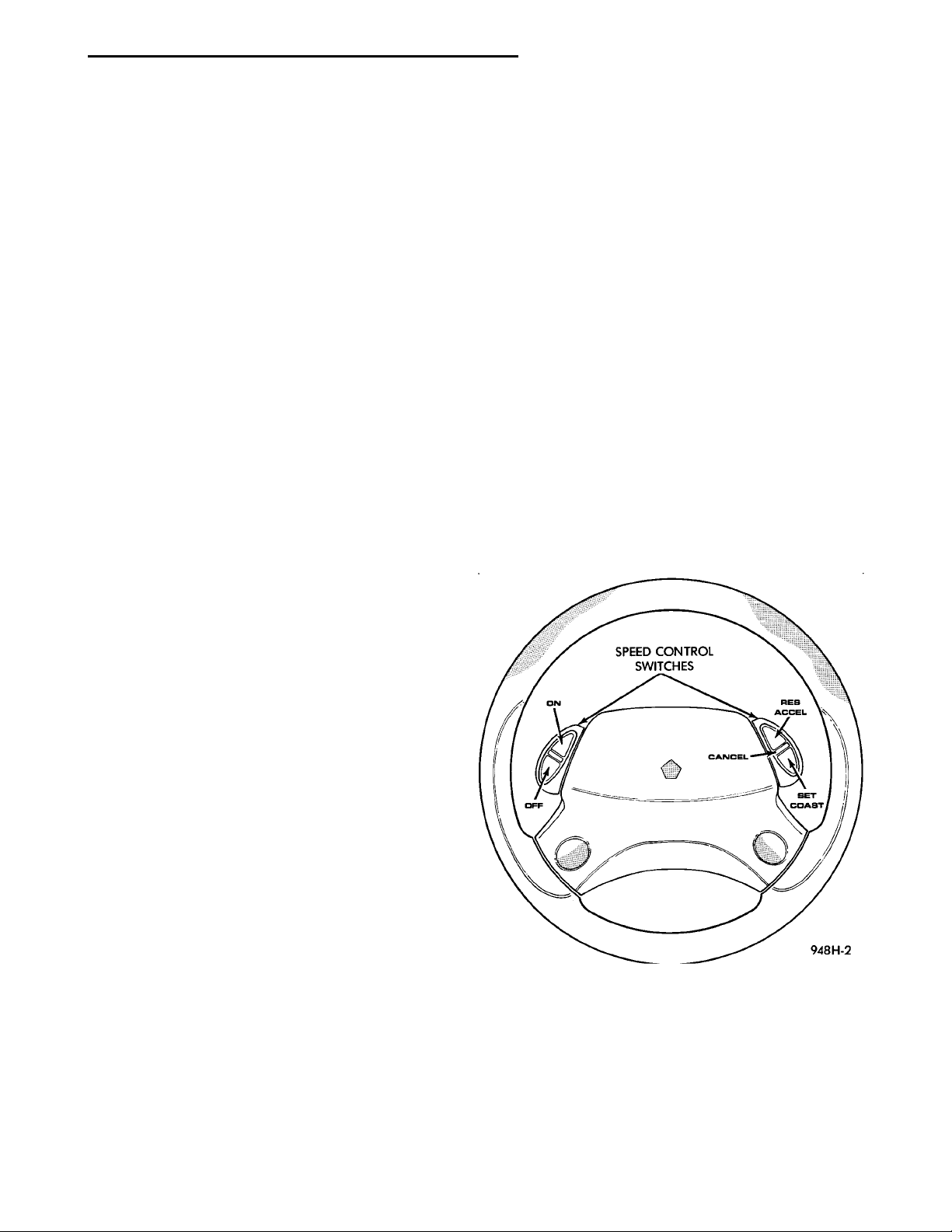
The speed control system is electronically controlled and vacuum operated. The electronic control
is integrated into the powertrain control module
which is located in the engine compartment. The controls are located on the steering wheel and consist of
five switches. The ON and OFF buttons are located
on the left side of the airbag module. The RESUME/
ACCEL, SET/COAST and CANCEL buttons are
located on the right side of the airbag module (Fig.
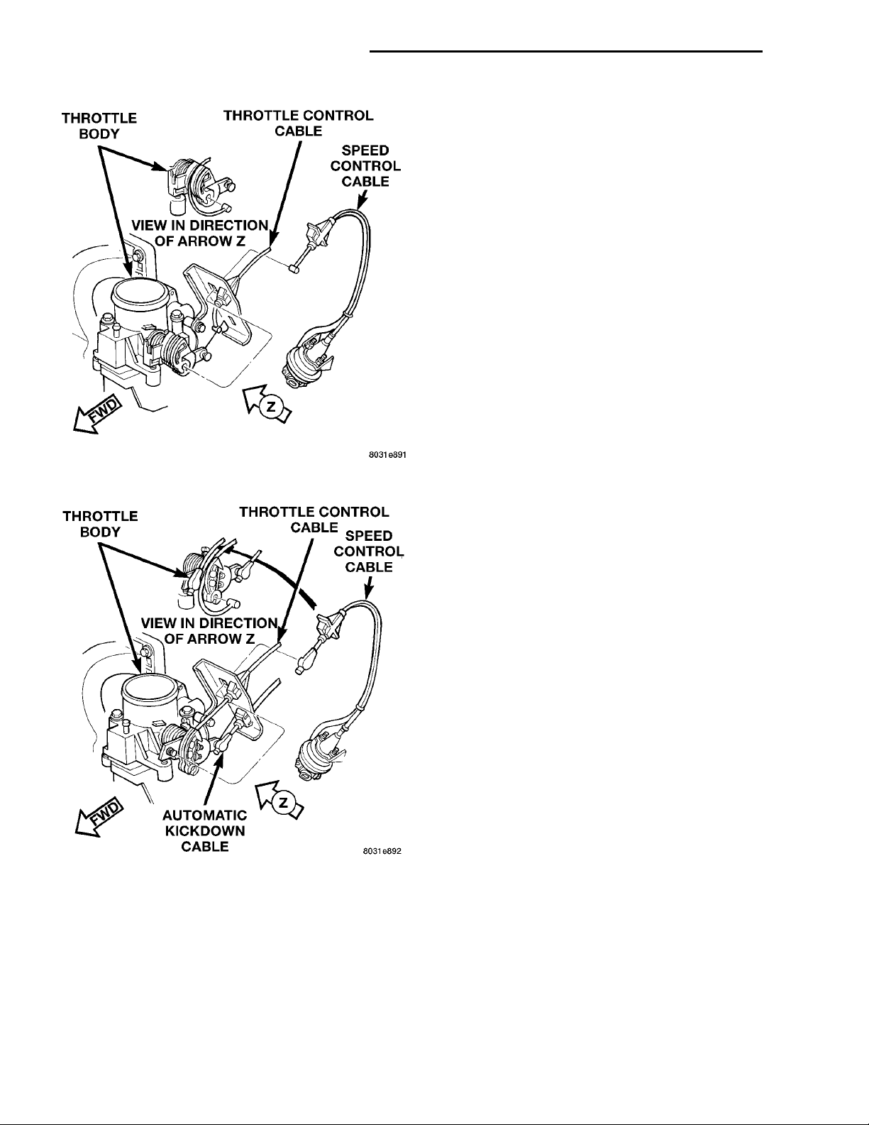
1). For identification and location of the major components (Fig. 2) and (Fig. 3).
The system is designed to operate at speeds above
30 mph (50 km/h).
ROAD TEST ............................ 3
SERVO VACUUM TEST ................... 7
SPEED CONTROL ELECTRICAL TEST ....... 5
SPEED CONTROL SWITCH TEST ........... 7
STOP LAMP SWITCH TEST ................ 8
VACUUM SUPPLY TEST .................. 9
VEHICLE SPEED SENSOR ................ 9
REMOVAL AND INSTALLATION
POWERTRAIN CONTROL MODULE ......... 11
SPEED CONTROL SERVO CABLE .......... 10
SPEED CONTROL SERVO ................ 9
SPEED CONTROL SWITCH ............... 10
STOP LAMP SWITCH .................... 10
VACUUM RESERVOIR ................... 11
VEHICLE SPEED SENSOR ............... 11
WARNING: THE USE OF SPEED CONTROL IS NOT
RECOMMENDED WHEN DRIVING CONDITIONS DO
NOT PERMIT MAINTAINING A CONSTANT SPEED,
SUCH AS IN HEAVY TRAFFIC OR ON ROADS THAT
ARE WINDING, ICY, SNOW COVERED, OR SLIPPERY.
Fig. 1 Speed Control Switch
Page 2
THROTTLE BODY VIEW IN DIRECTIONOF ARROW Z THROTTLE CONTROLCABLESPEED CON-TROL CABLEFWD
THROTTLE BODY VIEW IN DIRECTION OFARROW ZTHROTTLECONTROLCABLESPEED CONTROLCABLEAUTOMATIC KICKDOWNCABLEFWD
8H - 2 VEHICLE SPEED CONTROL SYSTEM PL
SPEED CONTROL SWITCHES
There are two separate switch pods that operate
the speed control system. The steering-wheelmounted switches use multiplexed circuits to provide
inputs to the PCM for ON, OFF, RESUME/ACCELERATE, SET/COAST and CANCEL modes. Refer to
the owner’s manual for more information on speed
control switch functions and setting procedures.
When speed control is selected by depressing the
ON switch, the PCM allows a set speed to be stored
in RAM for speed control. To store a set speed,
depress the COAST/SET switch while the vehicle is
moving at a speed between 30 and 85 mph. In order
for the speed control to engage, the brakes cannot be
applied, nor can the gear selector be indicating the
transmission is in Park or Neutral.
The speed control can be disengaged manually by:
• Stepping on the brake pedal
• Depressing the OFF switch
• Depressing the CANCEL switch.
The speed control can be disengaged also by any of
the following conditions:
Fig. 2 MTX Speed Control System
• An indication of Park or Neutral
• The VSS signal increases at a rate of 10 mph
per second (indicates that the co-efficient of friction
between the road surface and tires is extremely low)
• An rpm increase without a VSS signal increase
(indicates that the clutch has been disengaged)
• Excessive engine rpm (indicates that the trans-
mission may be in a low gear)
• The VSS signal decreases at a rate of 10 mph
per second (indicates that the vehicle may have
decelerated at an extremely high rate)
• If the actual speed is not within 20 mph of the
set speed
The previous disengagement conditions are pro-
grammed for added safety.
Once the speed control has been disengaged,
depressing the RES/ACCEL switch restores the vehicle to the target speed that was stored in the PCM’s
RAM.
Fig. 3 ATX Speed Control System
DESCRIPTION AND OPERATION
SPEED CONTROL SERVO
The servo unit consists of a solenoid valve body,
and a vacuum chamber. The PCM controls the solenoid valve body. The solenoid valve body controls the
application and release of vacuum to the diaphragm
of the vacuum servo. The servo unit cannot be
repaired and is serviced only as a complete assembly.
NOTE: Depressing the OFF switch will erase the
set speed stored in the PCM’s RAM.
If, while the speed control is engaged, the driver
wishes to increase vehicle speed, the PCM is programmed for an acceleration feature. With the RES/
ACCEL switch held closed, the vehicle accelerates
slowly to the desired speed. The new target speed is
stored in the RAM when the RES/ACCEL switch is
released. The PCM also has a “tap-up” feature in
which vehicle speed increases at a rate of approximately 2 mph for each momentary switch activation
of the RES/ACCEL switch.
The PCM also provides a means to decelerate without disengaging speed control. To decelerate from an
Page 3

PL VEHICLE SPEED CONTROL SYSTEM 8H - 3
DESCRIPTION AND OPERATION (Continued)
existing recorded target speed, depress and hold the
SET/COAST switch until the desired speed is
reached. Then release the switch. The ON and OFF
switches operates two components: the PCM’s
ON/OFF input, and the battery voltage to the brake
switch, which powers the speed control servo.
The individual switches cannot be repaired. If one
switch fails, the entire switch module must be
replaced.
STOP LAMP SWITCH
Vehicles equipped with the speed control option use
a dual function stop lamp switch. The switch is
mounted in the same location as the conventional
stop lamp switch, on the brake pedal mounting
bracket under the instrument panel. The PCM monitors the state of the dual function stop lamp switch.
Refer to Group 5, Brakes for more information on
stop lamp switch service and adjustment procedures.
SERVO CABLE
The speed control servo cable is connected between
the speed control vacuum servo diaphragm and the
throttle body control linkage. This cable causes the
throttle control linkage to open or close the throttle
valve in response to movement of the vacuum servo
diaphragm.
POWERTRAIN CONTROL MODULE
The speed control electronic control circuitry is
integrated into the Powertrain Control Module
(PCM). The PCM is located in the engine compartment. The PCM speed control functions are monitored by the On-Board Diagnostics (OBD). All OBDsensed systems are monitored by the PCM. Each
monitored circuit is assigned a Diagnostic Trouble
Code (DTC). The PCM will store a DTC in electronic
memory for any failure it detects. See On-Board
Diagnostic Tests in this group for more information.
The PCM cannot be repaired and must be replaced if
faulty.
VACUUM RESERVOIR
The reservoir contains a one-way check valve to
trap engine vacuum in the reservoir. When engine
vacuum drops, as in climbing a grade while driving,
the reservoir supplies the vacuum needed to maintain proper speed control operation. The vacuum reservoir cannot be repaired and must be replaced if
faulty.
VEHICLE SPEED SENSOR
The Vehicle Speed Sensor (VSS) is a pulse generator mounted to an adapter near the transmission output shaft. The sensor is driven through the adapter
by a speedometer pinion gear. The VSS pulse signal
to the speedometer/odometer is monitored by the
PCM speed control circuitry to determine vehicle
speed and to maintain speed control set speed. Refer
to the appropriate Powertrain Diagnostic Procedures
manual for diagnosis and testing of this component.
Refer to Group 14, Fuel System for removal/installation procedures.
DIAGNOSIS AND TESTING
ROAD TEST
Perform a vehicle road test to verify reports of
speed control system malfunction. The road test
should include attention to the speedometer. Speedometer operation should be smooth and without flutter at all speeds.
Flutter in the speedometer indicates a problem
which might cause surging in the speed control system. The cause of any speedometer problems should
be corrected before proceeding. Refer to Group 8E,
Instrument Panel and Gauges for speedometer diagnosis.
If a road test verifies an inoperative system, and
the speedometer operates properly, check for:
• A Diagnostic Trouble Code (DTC). If a flash
lamp code 15, 34 or 77 exists at the Check Engine
Lamp (MIL), conduct tests per the Powertrain Diagnostic Procedures service manual.
• A misadjusted brake (stop) lamp switch. This
could also cause an intermittent problem.
• Loose or corroded electrical connections at the
servo. Corrosion should be removed from electrical
terminals and a light coating of Mopar MultiPurpose
Grease, or equivalent, applied.
• Loose or leaking vacuum hoses or connections.
• Secure attachment at both ends of the speed
control servo cable.
• Smooth operation of throttle linkage and throttle
body air valve.
• Failed speed control servo. Do the servo vacuum
test.
CAUTION: When test probing for voltage or continuity at electrical connectors, care must be taken
not to damage connector, terminals or seals. If
these components are damaged, intermittent or
complete system failure may occur.
CHECKING FOR DIAGNOSTIC CODES
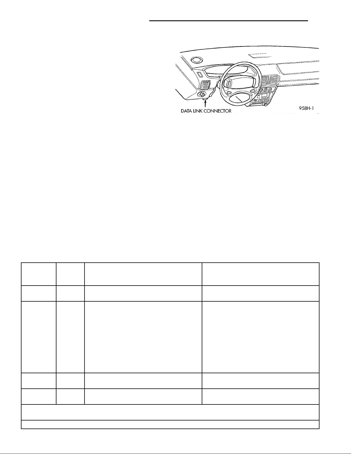
When trying to verify a speed control system electronic malfunction: Connect a DRB scan tool if available to the data link connector (Fig. 4). The connector
is located at left side of the steering column, and at
lower edge of the panel.
Page 4
DATA LINK CONNECTOR
8H - 4 VEHICLE SPEED CONTROL SYSTEM PL
DIAGNOSIS AND TESTING (Continued)
If a scan tool is not available, use the following
procedure:
(1) With key inserted in ignition switch, cycle
switch to ON position three times. On third cycle,
leave switch in ON position.
(2) After switch has been cycled three times,
observe MALFUNCTION INDICATOR LAMP (check
engine) indicator on instrument cluster. If a diagnostic code is present, indicator will flash (blink) in a
series which will show which diagnostic code is the
problem. EXAMPLE: A series of three flashes in
rapid succession, a slight pause, then four flashes in
rapid succession would indicate diagnostic code 34.
(3) A speed control malfunction may occur without
either diagnostic code being indicated. If no diagnostic code appears conduct test in the following paragraphs depending on failure mode. If code 15 or 34 is
observed, refer to the appropriate Powertrain Diagnostic Manual for the electrical circuit diagnostic..
Refer to Group 25, for further information and useage of the DRB scan tool and a more complete list of
Diagnostic Trouble Code.
resume ACCEL/SWITCH.
servo. Test continuity of pin 1 to ground to test for
intermittent short. Wiggle wires while preforming
test.
Fig. 4 Data Link Connector Location
(1) Conduct the speed control switch test on the
(2) If it failes, replace switch.
(3) If it passes, disconnect the 4 way connector at
(4) If continuity to ground, repair wiring.
(5) If no continuity to ground, replace PCM.
SPEED CONTROL ACCELERATES OR TAPS UP
BY ITSELF
Check for diagnostic trouble codes. If code 15 refer
to the Powertrain Diagnostic Manual, if code 34 perform the following test:
SPEED CONTROL SLOWS DOWN BY ITSELF
Test vehicle speed sensor, refer to group 8E. If sensor fails replace sensor, if it passes perform the following test:
(1) Perform the speed control switch test on the
SET/COAST switch, if it fails replace switch.
SPEED CONTROL DIAGNOSTIC TROUBLE CODES
Diagnostic
Trouble
Hex
Code
DRB Scan Tool Display Description of Diagnostic Trouble Code
Code
15** No Vehicle Speed Sensor Signal No vehicle distance (speed) sensor signal
detected during road load conditions.
34* OF Speed Control Solenoid Circuits An open or shorted condition detected in
the Speed Control vacuum or vent
solenoid circuits.
or
56 MUX S/C Switch High Speed control switch input above the
maximum acceptable voltage.
or
57 MUX S/C Switch Low Speed control switch input below the
minimum acceptable voltage.
55* N/A Completion of fault code display on Check
Engine Lamp.
77 52 S/C Power Relay Circuit Malfunction detected with power feed to
speed control servo soleniods.
* Check Engine Lamp will not illuminate at all times if this Diagnostic Trouble Code was recorded. Cycle ignition
key as described in manual and observe code flashed by Check Engine Lamp.
** Check Engine Lamp will illuminate during engine operation if this Diagnostic Trouble Code was recorded.
Page 5

PL VEHICLE SPEED CONTROL SYSTEM 8H - 5
DIAGNOSIS AND TESTING (Continued)
(2) If the switch passes, conduct the vacuum sup-
ply test.
(3) If it passes, conduct the servo vacuum test. If it
fails replace servo.
(4) If it passes, test continuity of pin 2 of harness
connector to PCM pin 80 for intermittent open. Wiggle wires while performing this test. If no continuity
to pin 80, repair harness for open.
(5) If no continuity, replace the PCM.
SPEED CONTROL WILL NOT RESUME-SETS OK
Perform the speed control switch test on the
RESUME/ACCEL switch. If the switch fails replace
switch.
(1) If switch passes, check continuity from
RESUME/ACCEL switch connector pin 1 to pin 41 of
40 way connector at PCM. Check for intermittent
open circuit, wiggle wires while performing test.
(2) If intermittent open, repair circuit.
(3) If continuity is ok, perform continuity test from
pin 1 of RESUME/ACCEL switch connector to
ground. Check for intermittent short, wiggle wires
while performing this test.
(4) If shorted, repair harness for short.
(5) If continuity, disconnect the servo connector.
Test continuity from pin 2 of connector and ground to
test for intermittent short. Wiggle wires while preforming test. If continuity repair circuit.
(6) If no continuity, conduct the servo vacuum test.
If it fails, replace servo.
(7) If it passes, replace PCM.
SPEED CONTROL ELECTRICAL TEST
Electronic speed control systems may be tested
using two different methods. One involves use of a
DRB. If this test method is desired, refer to the Powertrain Diagnostic Test Procedures for charging and
speed control system manual.
The other test method uses a volt/ohm meter. The
volt/ohm meter method is described in the following
tests.
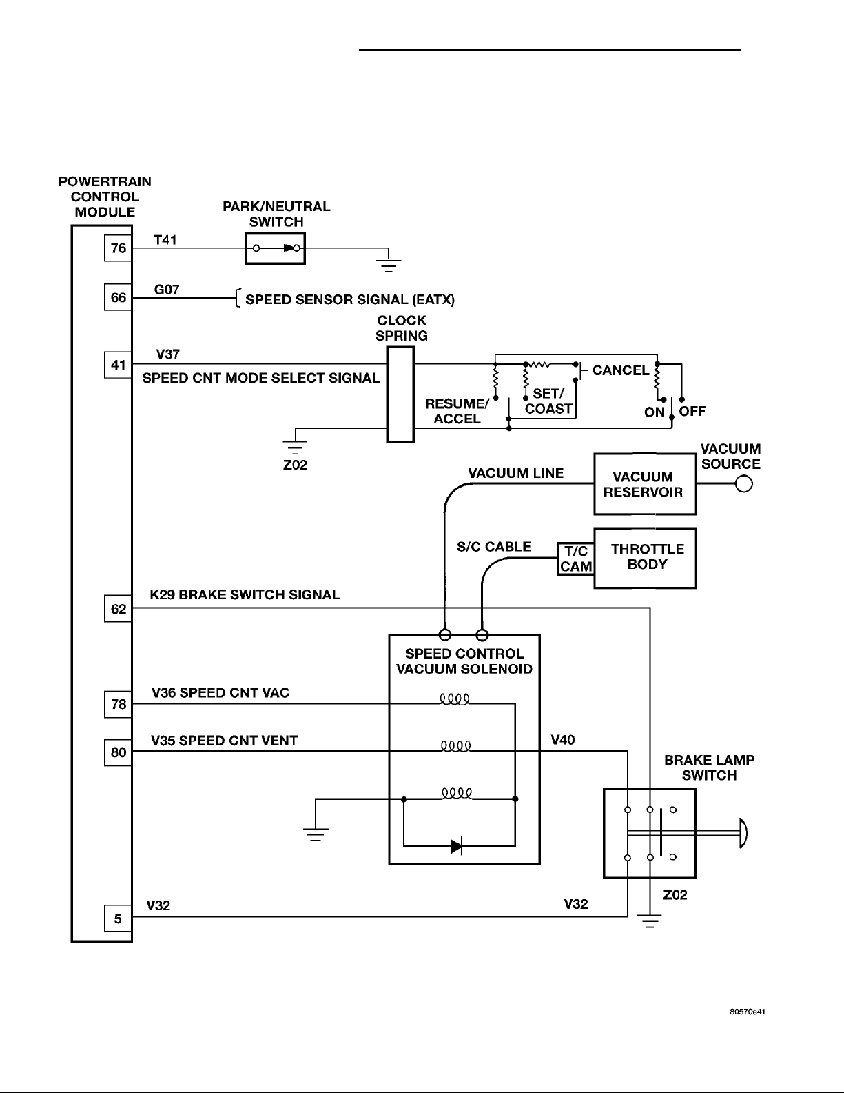
If any information is needed concerning wiring,
refer to Group 8W, Wiring Diagrams (Fig. 5).
CAUTION: When test probing for voltage or continuity at electrical connectors, care must be taken
not to damage connector, terminals, or seals. If
these components are damaged, intermittent or
complete system failure may occur.
SPEED CONTROL WILL NOT SLOW DOWN
Check for diagnostic trouble codes. If code 34 or no
code perform the following test:
(1) Conduct the speed control switch test on the
resume SET/COAST.
(2) If it fails, replace switch.
(3) If it passes use an ohmeter to test continuity
between pin 1 of SET/COAST switch connector and
ground. Wiggle wires while preforming test. If no
continuity, repair circuit.
(4) If continuity, test continuity between pin 2 of
SET/COAST switch connector and pin 41 of the PCM
40 way connector. Wiggle wires while preforming
test. If no continuity, repair circuit.
When electrical connections are removed, corrosion
should be removed from electrical terminals and a
light coating of Mopar Multi-Purpose Grease, or
equivalent, applied. Inspect connectors for damage
terminals.
A poor connection can cause a complete or intermittent malfunction and is also the only connection
in the circuit, that can not be tested. For this reason,
a loose connection may be misdiagnosed as a component malfunction.
Page 6
POWERTRAIN CONTROLMODULE PARK/NEUTRAL SWITCHSPEED SENSOR SIGNAL(EATX) CLOCKSPRINGRESUME/ACCEL SET/COAST CANCEL ONOFFVACUUM SOURCEVACUUM RESERVOIRVACUUM LINES/C CABLET/C CAMTHROTTLE BODYBRAKE LAMP SWITCHSPEED CONTROL VACUUMSOLENOIDV35 SPEED CNT VENTV36 SPEED CNT VACK29 BRAKE SWITCH SIGNALSPEED CNT MODE SELECTSIGNAL
8H - 6 VEHICLE SPEED CONTROL SYSTEM PL
DIAGNOSIS AND TESTING (Continued)
Fig. 5 Speed Control Circuit
Page 7
PL VEHICLE SPEED CONTROL SYSTEM 8H - 7
DIAGNOSIS AND TESTING (Continued)
OVERSHOOT/UNDERSHOOT ON SPEED CONTROL SET
If the operator repeatedly presses and releases the
set button with their foot off of the accelerator (a “lift
foot set” to begin speed control operation), the vehicle
may accelerate and exceed the desired set speed by
up to 5 MPH (8 km/h) and then decelerate to less
than the desired set speed before finally achieving
the desired set speed.
The Speed Control has an adaptive strategy that
compensates for vehicle-to-vehicle variations in speed
control cable lengths. When the speed control is set
with the vehicle operators foot off of the accelerator
pedal, the speed control thinks there is excessive
speed control cable slack and adapts. If the lift foot
sets are continually used, the speed control overshoot/undershoot condition will develop.
To “unlearn” the overshoot/undershoot condition,
the vehicle operator has to press and release the set
button while maintaining the desired set speed with
the accelerator pedal (not decelerating or accelerating), and then turn the cruise control switch to the
OFF position (or press the CANCEL button if
equipped) after waiting 10 seconds. This procedure
must be performed approximately 10–15 times to
completely unlearn the overshoot/undershoot condition.
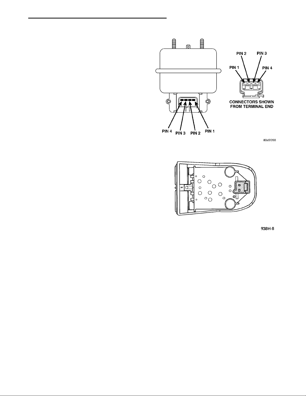
Fig. 6 Servo Harness Connector
SERVO VACUUM TEST
(1) Turn ignition switch to the ON position without starting engine. Activate speed control ON
switch.
(2) Disconnect the four-way electrical connector
and the vacuum harness at the servo (Fig. 6).
(3) Connect a jumper wire from Pin 3 of the servo
to Pin 3 of the wire connector.
(4) Ground Pins 2 and 4 in the servo. Do not connect pin 1.
(5) Connect a hand held vacuum pump to the vacuum nipple and apply 10 - 15 inches of vacuum.
(6) If servo pulls cables, replace servo.
(7) Ground Pin 1 on servo.
(8) Check that the throttle cable pulls in and holds
as long as the vacuum pump is connected. After one
minute, check if cable is still holding. If cable does
not hold replace the servo.
(9) Disconnect jumper from pin 3. Cable should
return to rest position. If not, replace servo.
(10) Connect 4 way electrical connector and vacuum harness to servo.
SPEED CONTROL SWITCH TEST
The speed control switches mounted on the steering wheel contain five switches and four resistors.
The PCM sends 5 volts through pin 41 to the speed
control switches. The input on pin 41 is responsible
Fig. 7 Speed Control Switch
for identifying the following: Resume/Accelerate, Set/
Coast, On, Off and Cancel. This is accomplished by
multiplexing. Multiplexing allows the PCM to identify more than one signal from a single wire. To
accomplish this, the speed control switch uses resistors that cause different voltage signals at pin 41.
The 5-volt signal at pin 41 has no path to ground
when no buttons are depressed, allowing the PCM to
recognize the open circuit. When the ON, OFF switch
contacts are closed, the 5 volt signal is pulled
through a 15400 ohm resistor to ground providing a
voltage of 4.14 to 4.73 volts at pin 41. Once the PCM
recognizes the ON signal, the PCM provieds a battery voltage signal to the speed control servo through
pin 5 of the 80–way connector.
When the SET/COAST switch is depressed, a
momentary contact closes a path to ground through a
2,940 ohm resistor. This causes a voltage of approximately 1.99 to 3.20 volts at pin 41, indicating that
the SET/COAST switch has been depressed. When
the RES/ACCEL switch is depressed, a momentary
Page 8
8H - 8 VEHICLE SPEED CONTROL SYSTEM PL
DIAGNOSIS AND TESTING (Continued)
contact closes to ground through a 6,650 ohm resistor. The 5-volt signal then passes through a higher
resistance than that of the SET/COAST switch, causing the voltage to be approximately 3.30 to 4.14 volts.
When the OFF switch is depressed, the contacts close
directly to ground, causing the 5-volt signal to drop
to 0 volts. When the CANCEL is pressed the contact
closes to ground through a 920 ohm resister, causing
voltage at pin 41 of 0.61 to 1.94 volts.
OHMMETER CHECK OF SWITCH
(1) Remove the ON, OFF speed control switch
assembly and disconnect the two-way connector (Fig.
7).
(2) Using an ohmmeter, touch one lead to one Pin
and the second lead to the other Pin. The meter
should read no continuity. Press the OFF button, the
ohmmeter should read 0 to 0.5 ohms. Press the ON
button, the ohmmeter should read 15,245 to 15,555
ohms. If the resistance does not fall within these values replace switch.
(3) Remove the RESUME/SET/CANCEL speed
control switch assembly and disconnect the two-way
connector.
(4) Using an ohmmeter, touch one lead to one Pin
and the second lead to the other Pin. The meter
should read no continuity. Press the SET button, the
ohmmeter should read 2,910 to 2,970 ohms. Press the
RESUME button, the ohmmeter should read 6,580 to
6,720 ohms. Press the CANCEL button, the ohmmeter should read 900 to 920 ohms. If the resistance
values do not fall within these specification replace
the switch.
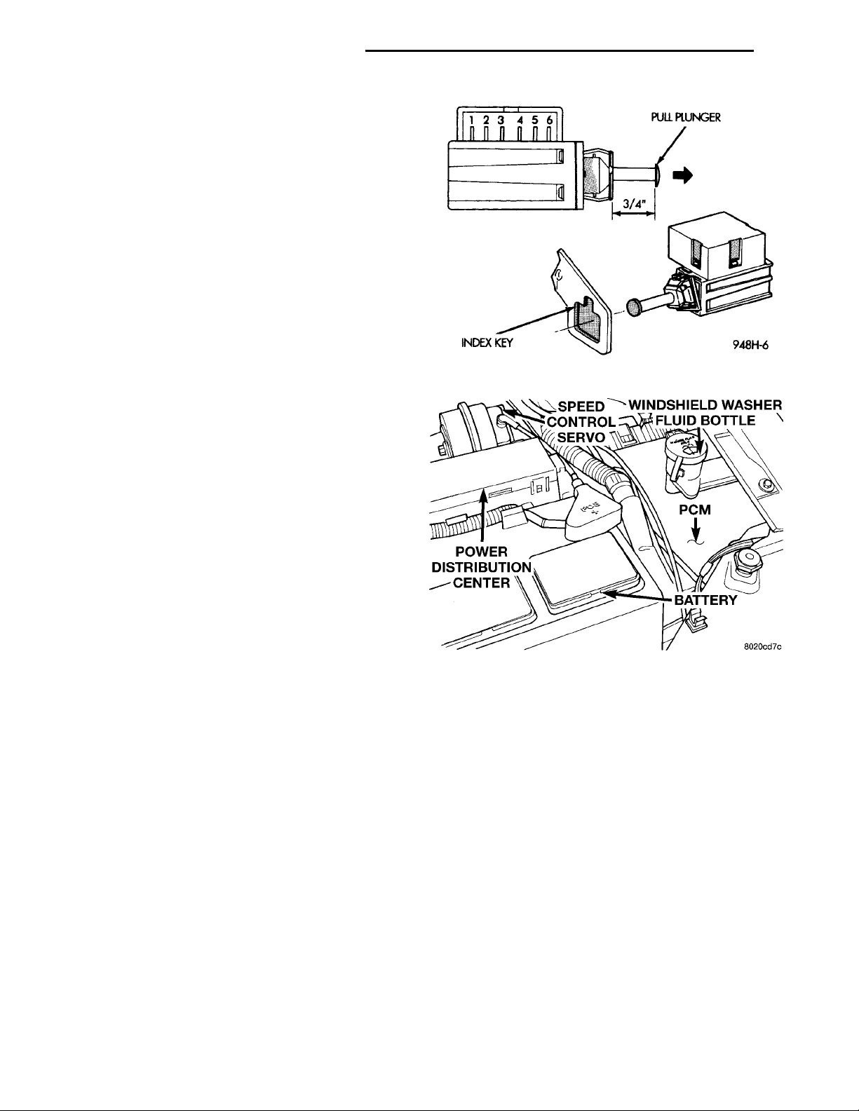
Fig. 8 Stop Lamp Wiring
STOP LAMP SWITCH TEST
(1) Remove the stop lamp switch refer to Stop
Switch Removal/Installation in this section. Disconnect connector from stop lamp switch (Fig. 8). Using
an ohmmeter, switch continuity may be checked as
follows:
(2) With switch plunger released, there should be
continuity between Pin 5 and Pin 6.
(3) With switch plunger depressed, there should be
continuity:
• Between Pin 1 and Pin 2.
• Between Pin 3 and Pin 4.
(4) If the above results are not obtained, the stop
lamp switch is defective or out of adjustment.
(5) Stop lamp switch adjustment is detailed in
Group 5, Brakes.
ELECTRICAL TESTS AT POWERTRAIN CONTROL MODULE
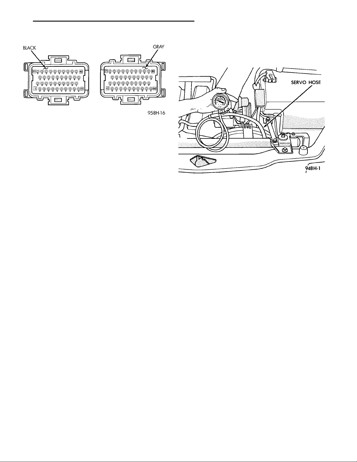
(1) Unplug 2 40-way connectors from the Power-
train Control Module (PCM), located (Fig. 9).
Fig. 9 Powertrain Control Module Location
(2) Remove both steering wheel speed control
switches and disconnect the wire connectors.
(a) Using an ohmmeter, check for continuity
between pin 41 of the PCM connector and pin 1 of
each speed control switch connector (Fig. 10).
(b) If no continuity, repair as necessary.
(c) Using an ohmeter, check for continuity
between pin 41 of the PCM connector and ground.
(d) If no continuity, repair as necessary.
(e) If continuity, perform the Switch Test.
(3) Place ignition switch in the ON position for the
following tests.
(a) Connect wire connectors to both switches.
(b) Using a voltmeter, connect the ground lead to
ground.
(c) Touch the positive lead of the voltmeter to
pin 5 on the PCM. Depress the ON switch, the
voltmeter should read battery voltage. Depress
OFF switch, the voltmeter should read 0 volts. If
no voltage, repair wire between pin 80 and pin 2 of
the servo. If OK, go to step 4.
Page 9
PL VEHICLE SPEED CONTROL SYSTEM 8H - 9
DIAGNOSIS AND TESTING (Continued)
VACUUM SUPPLY TEST
(1) Disconnect vacuum hose at the servo and
install a vacuum gauge in the hose (Fig. 11).
Fig. 10 PCM 40—Way Connectors
(d) Reconnect the BLACK connector (with pins
1–40) to PCM.
(e) Touch the positive lead of the voltmeter to
the harness connector pin 80. Depress OFF switch,
the voltmeter should read 0 volts. Depress ON
switch, the voltmeter should read battery voltage.
If no voltage, go to step 5. Repair the wire between
pin 78 and 1 of the speed control servo. If OK, go
to step 5.
(4) Disconnect the 4 way connector at the servo.
Depress the ON switch. The voltmeter should read
battery volts at pin 3. If no voltage go to step 7. If
voltage is OK, repair wire between pin 80 and pin 2
of the servo.
(5) Reconnect the 4 way connector to servo.
(6) Touch the positive lead of the voltmeter to the
harness connector pin 80. Depress OFF switch, the
voltmeter should read 0 volts. Depress ON switch,
the voltmeter should read battery voltage. If no voltage, go to step 5. Repair the wire between pin 80 and
pin 1 of the speed control servo. If OK, go to step 5.
(7) Turn key off.
(8) Using an ohmmeter, connect one lead to ground
and touch the other lead to pin 62. With the brake
pedal released, the meter should show continuity. If
no continuity, perform the following test:
(a) Check for continuity between pin 62 and pin
3 of the stop lamp switch connector. If no continuity, repair as necessary.
(b) If continuity, perform Stop Lamp Switch
Test.
(9) If the Stop Lamp Switch Test is OK, check for
continuity between pin 6 of the stop lamp switch and
ground. When the pedal is depressed, the meter
should show open circuit. If no continuity repair as
necessary. If OK, go to step 8.
(10) Using an ohmmeter, touch one lead to a
ground and touch the other lead to pin 76. The meter
should show no continuity when transmission is in
DRIVE and continuity when in PARK or NEUTRAL.
If not, test Neutral Start and Back-Up switch using
scan tool.
uum gauge should read at least ten inches of mercury. Shut off engine, the vacuum should continue to
hold 10 inches of mercury.
check and correct the following vacuum leaks in the
vacuum lines, check valve, vacuum reservoir or poor
engine performance.
VEHICLE SPEED SENSOR
sor (VSS), refer to the appropriate Powertrain Diagnostic Procedures service manual. Also refer to the
DRB scan tool.
REMOVAL AND INSTALLATION
SPEED CONTROL SERVO
REMOVAL
INSTALLATION
bracket, tighten to 7 N·m (60 ins. lbs.).
Fig. 11 Vacuum Gauge Test—Typical
(2) Start engine and observe gauge at idle. Vac-
(3) If vacuum does not meet this requirement,
For diagnosis and testing of the Vehicle Speed Sen-
(1) Disconnect electrical connector from servo.
(2) Disconnect vacuum hoses from servo
(3) Remove 2 nuts retaining cable to servo.
(4) Remove hair pin holding cable to servo.
(1) Install hairpin to cable at servo.
(2) Install 2 nuts at cable to servo and servo
(3) Connect electrical connector to servo.
(4) Connect vacuum hose to servo
Page 10
MOUNTING TABTHROTTLE CONTROLSHIELDMOUNTING SCREW
8H - 10 VEHICLE SPEED CONTROL SYSTEM PL
REMOVAL AND INSTALLATION (Continued)
SPEED CONTROL SWITCH
The speed control switches are mounted in the
steering wheel and wired through the clock spring
device under the airbag module (Fig. 1).
WARNING: IF REMOVAL OF AIRBAG MODULE IS
NECESSARY, REFER TO GROUP 8M, RESTRAINT
SYSTEMS.
REMOVAL
(1) Turn off ignition.
(2) Remove two screws from side of each switch.
(3) Rock switch away from airbag and steering
wheel.
(4) Disconnect two-way electrical connector.
(5) Repeat for the other switch.
INSTALLATION
For installation reverse above procedures.
STOP LAMP SWITCH
REMOVAL
Remove the switch from the bracket by depressing
the brake pedal and rotating the switch in a counterclockwise direction approximately 30 degrees. Pull
the switch rearward and remove from bracket. Disconnect wiring harness connector.
(5) Disconnect electrical connector from servo.
(6) Disconnect vacuum hose from servo
(7) Remove 2 nuts retaining bracket to servo.
(8) Remove push nuts holding cable housing to
servo.
(9) Remove retaining clip holding cable to servo.
INSTALLATION
(1) Install retaining clip to cable at servo.
(2) Slide cable bell housing over servo mounting
studs.
(3) Install servo mounting studs into bracket.
(4) Install 2 nuts at cable to servo and servo
bracket, tighten to 7 N·m (60 ins. lbs.).
(5) Connect electrical connector to servo.
(6) Connect vacuum hose to servo
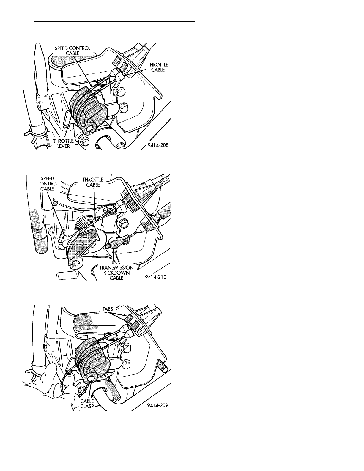
(7) Slide cable into throttle cable bracket and
engage retaining tabs.
(8) Rotate the throttle lever forward to the wide
open position and install speed control cable clasp.
(9) Rotate the throttle lever forward to the wide
open position and install throttle cable clasp.
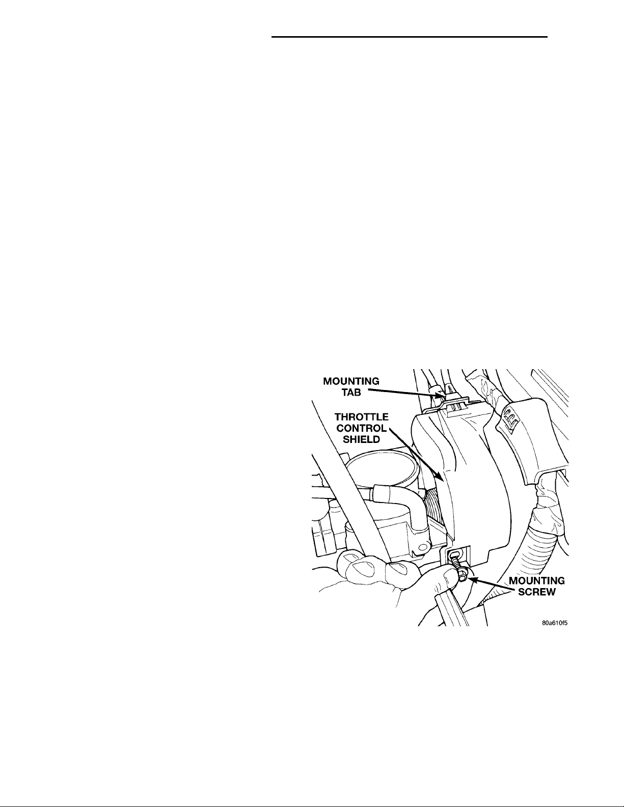
(10) Install throttle control shield. Tighten bolt to
5.6 N·m (50 in. lbs.).
INSTALLATION
Before installing the switch, reset the adjustable
switch plunger by pulling on the plunger head until
the plunger reaches the end of its travel. A ratcheting sound will be heard during this procedure.
Connect the wiring harness to the switch. Mount
the switch into the bracket by holding the switch
with the plunger facing forward in car. There is an
index key on the switch that mates with the bracket
slot at the top of the square hole. Align key and push
switch into square hole in bracket while depressing
the brake pedal. Once the switch is seated in the
hole, rotate clockwise approximately 30 degrees to
lock into place. The switch will automatically adjust
when the pedal is released. Pull back on the pedal to
assure correct adjustment.
SPEED CONTROL SERVO CABLE
REMOVAL
(1) Remove throttle control shield.
(2) Remove throttle clasp from the throttle body
lever.
(3) Remove speed control cable from throttle lever
by sliding clasp out hole used for throttle cable.
(4) Compress the retaining tabs on the cable and
slide cable out of bracket.
Fig. 12 Throttle Control Shield
Page 11
SPEED CON-TROL CABLE THROTTLECABLETRANSMISSIONKICKDOWN CABLE
SPEED CONTROLCABLE THROTTLECABLETHROTTLELEVER
CLASP
TABSCABLE
PL VEHICLE SPEED CONTROL SYSTEM 8H - 11
REMOVAL AND INSTALLATION (Continued)
POWERTRAIN CONTROL MODULE
For Removal/Installation refer to Powertrain Con-
trol Module in Group 14, Fuel Injection System.
VACUUM RESERVOIR
REMOVAL
(1) Raise and support vehicle.
(2) Remove bolt on top of vacuum reservoir.
(3) Remove vacuum hoses.
(4) Remove vacuum reservoir.
INSTALLATION
(1) Install vacuum reservoir, install push pin and
tighten screw to 5 N.m (44 in. lbs.)..
(2) Install vacuum hoses.
Fig. 13 Throttle Cable Attachment to Throttle
(3) Lower vehicle.
Body—Manual Transmission
VEHICLE SPEED SENSOR
For Removal/Installation, refer to Vehicle Speed
Sensor in Group 21, Transaxle.
Fig. 14 Throttle Cable Attachment to Throttle
Body—Automatic Transmission
Fig. 15 Disconnecting Throttle Cable
Page 12

 Loading...