

Page 1
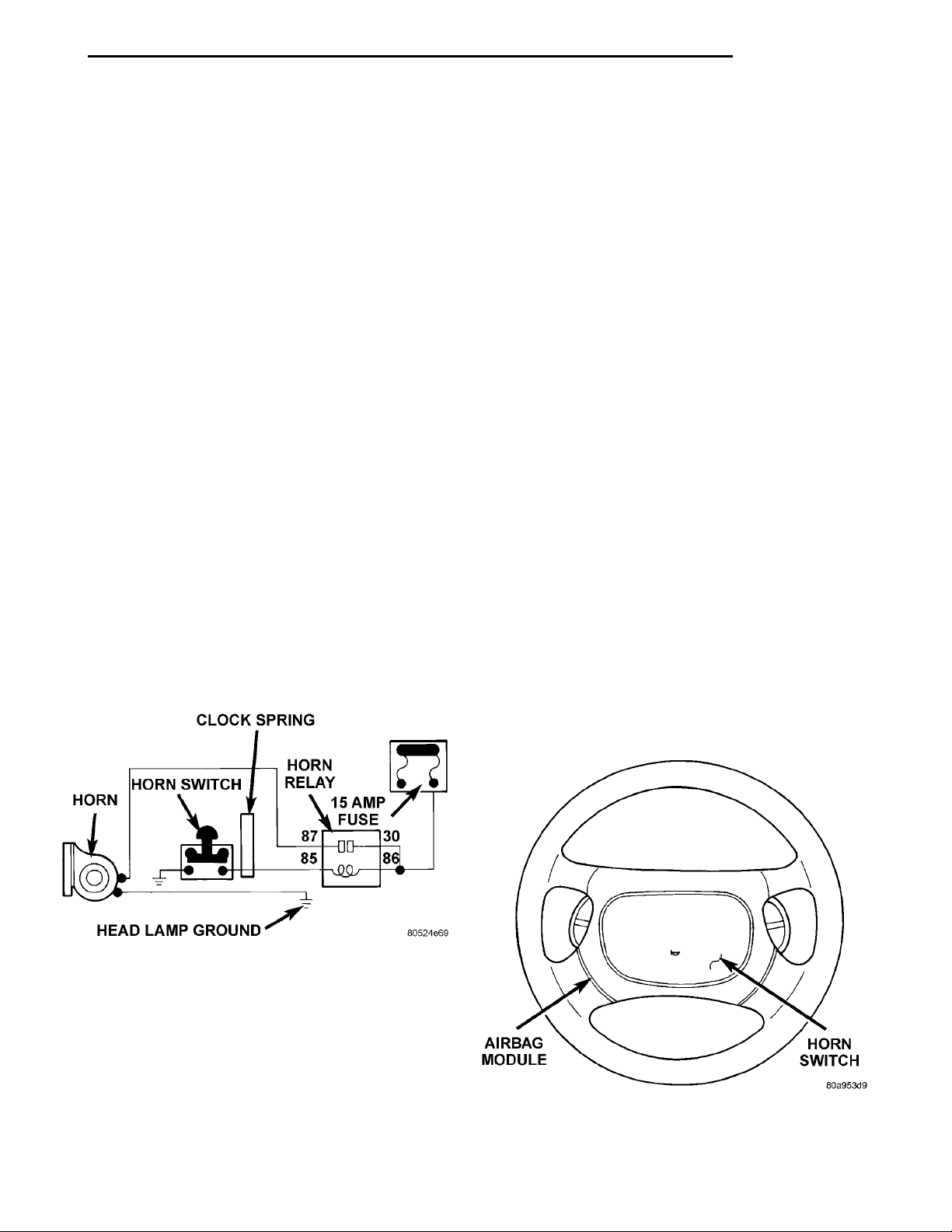
HEAD LAMP GROUND
HORNHORN SWITCH CLOCK SPRINGHORN RELAY15 AMPFUSE
AIRBAG MODULEHORN SWITCH
PL HORNS 8G - 1
HORNS
CONTENTS
page page
DESCRIPTION AND OPERATION
INTRODUCTION ........................ 1
DIAGNOSIS AND TESTING
HORN RELAY .......................... 2
HORN SWITCH ......................... 2
HORN ................................ 2
DESCRIPTION AND OPERATION
INTRODUCTION
WARNING: ON VEHICLES EQUIPPED WITH AIRBAG, SEE GROUP 8M, RESTRAINT SYSTEMS FOR
STEERING WHEEL OR COLUMN REMOVAL PROCEDURES.
The horn circuit consists of a horn switch, horn
relay, and horn. The horn circuit feed is from the fuse
to the horn relay in the Power Distribution Center
(PDC). The PDC is mounted on the battery tray.
When the horn switch is depressed, it completes the
ground circuit. The horn relay coil closes contacts
and allows current to flow to the horn. The horn is
grounded to the headlamp ground connection (Fig. 1).
SYSTEM TEST .......................... 3
REMOVAL AND INSTALLATION
HORN RELAY .......................... 5
HORN SWITCHES ....................... 5
HORN ................................ 5
have been clearly identified as LHD, RHD, or Export
if a special illustration or procedure is required.
HORN SWITCH
The horn switch is mounted between the outer and
inner cover of the Driver Airbag Module (Fig. 2).
When the Driver Airbag is pressed the horn switch
makes contact to ground. The ground signal is carried to the horn relay and the horn sounds.
(1) The horn switch grounds to the airbag housing.
(2) If horn does not sound check for corrosion:
• Horn wire
• Horn switch ground connected to airbag metal
housing
• Airbag to steering wheel
• Ensure horn wire is properly connected and
insulator is in place on wire
(3) Refer to Group 8W, Wiring Diagrams if wire
circuit needs to be repaired.
Fig. 1 Horn System
NOTE: This group covers both Left-Hand Drive
(LHD) and Right-Hand Drive (RHD) versions of this
model. Whenever required and feasible, the RHD
versions of affected vehicle components have been
constructed as mirror-image of the LHD versions.
While most of the illustrations used in this group
represent only the LHD version, the diagnostic and
service procedures outlined can generally be
applied to either version. Exceptions to this rule
Fig. 2 Horn Switch
Page 2
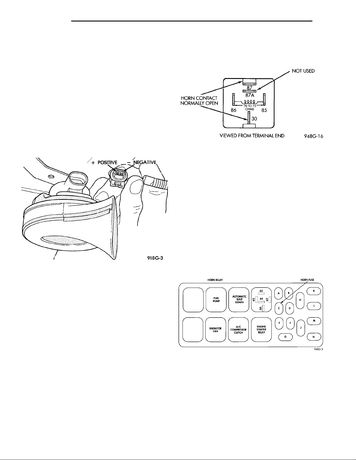
+ POSITIVE - NEGATIVE
NOT USED
VIEWED FROM TERMINALEND
HORN RELAY HORN FUSEFUEL PUMP AUTO-MATICSHUTDOWNRADI-ATOR FAN
A/C COMPRESSOR
CLUTCH
ENGINESTARTERRELAY
HORN CON-TACT NOR-MALLY OPEN
8G - 2 HORNS PL
DIAGNOSIS AND TESTING
HORN
(1) Disconnect wire connector at horn.
(2) Using a voltmeter, connect one lead to ground
terminal and the other lead to the positive wire terminal (Fig. 3).
(3) Depress the horn switch, battery voltage
should be present.
(4) If no voltage, refer to Horn System Test. If voltage is OK, go to Step 5.
(5) Using ohmmeter, test ground wire for continuity to ground.
(6) If no ground repair as necessary.
(7) If wires test OK and horn does not sound,
replace horn.
Fig. 3 Horn and Connector
(5) Check relay for 70 to 75 ohms resistance from
terminal 85 to 86 (Fig. 4). If resistance not OK,
replace relay.
Fig. 4 Horn and Connector
HORN SWITCH
(1) Remove horn relay from the Power Distribution
Center.
(2) Using ohmmeter, connect one lead to ground
and the other lead to cavity 65 of the power distribution center (Fig. 5).
(3) Depress horn switch, should have continuity. If
no continuity go to Step 4.
(4) Test continuity at horn switch, remove the
Driver Airbag Module. Refer to Driver Airbag Module
Removal and Installation procedures.
(5) Using ohmmeter, connect one lead to the airbag module ground and the other lead to B+ wire
(Fig. 6).
(6) Depress horn switch, and the meter should
show continuity. If no continuity, replace the Driver
Airbag Module. If OK, repair as necessary.
HORN RELAY
(1) Remove horn relay.
(2) Using ohmmeter, test for continuity between
ground and circuit 65 of horn relay.
(a) When the horn switch is not depressed, no
continuity should be present.
(b) Continuity to ground when horn switch is
depressed.
(c) If continuity is not correct repair horn switch
or wiring as necessary, refer to Group 8W, Wiring
Diagrams.
(3) Insert a jumper wire between circuit 63 and 66
of the Power Distribution Center.
(a) If horn sounds replace relay.
(b) If the horn does not sound, install horn relay
and refer to Horn Test.
(4) Using voltmeter, test voltage at:
(a) Circuit 62 and 66 test for battery voltage
from fuse C to body ground.
(b) If voltage is incorrect repair as necessary.
Refer to Group 8W, Wiring Diagrams.
Fig. 5 Power Distribution Center
Page 3
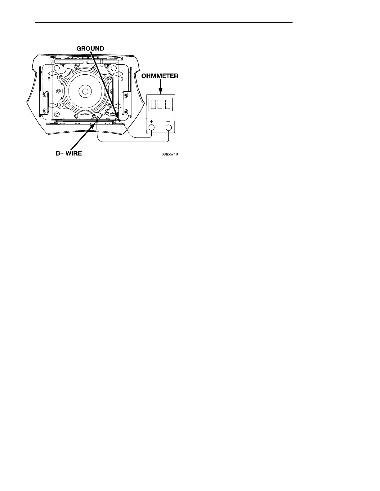
GROUNDOHMMETERB+ WIRE
PL HORNS 8G - 3
DIAGNOSIS AND TESTING (Continued)
SYSTEM TEST
Refer to Horn System Test below. If the horn does
not sound, check horn fuse located in the Power Distribution Center. If the fuse is blown, replace with
the correct fuse. If the horn fail to sound and the
new fuse blows when depressing the horn switch, a
short circuit in the horn or the horn wiring between
the fuse terminal and the horn is responsible, or a
defective horn switch allowed the horn to burn out is
responsible.
If the fuse is OK, test horn relay refer to Horn
Relay Test.
If the relay is OK, test horn refer to Horn Test.
CAUTION: Continuous sounding of horn may
cause horn relay to fail.
Fig. 6 Test Horn Switch - Driver Airbag Module
Should the horn sound continuously:
• Unplug the horn relay from Power Distribution
Center.
• Refer to Horn Relay Test.
Refer to Group 8W, wiring Disgrams for circuit and
wiring information.
Page 4

8G - 4 HORNS PL
REMOVAL AND INSTALLATION (Continued)
HORN SYSTEM TEST
CONDITION POSSIBLE CAUSE CORRECTION
Horn sounds continuously.
NOTE: Immediately unplug horn
relay in the Power Distribution
Center (PDC)
Horn sound intermittently as the
steering wheel is turned.
Horn does not sound (1) Check fuse 23 in PDC
Fuse blows when horn sounds (1) Short circuit in horn or horn
Fuse blows without blowing horn (1) Short circuit (1) Remove relay, install new fuse, if
NOTE: For wiring repairs refer to
Group 8W, Wire Diagrams.
(1) Faulty horn relay.
(2) Horn control circuit to relay
shorted to ground.
(3) Pinched horn switch wire under
Driver Airbag Module.
(4) Defective horn switch
(1) Horn relay control circuit X3 is
shorted to ground inside steering
wheel.
(2) Pinched horn switch wire under
Driver Airbag Module
(3) Defective horn switch
(2) No Voltage at horn RELAY
TERMINALS 62 & 66, and fuse is
OK.
(3) Open circuit from terminal 65 of
the horn relay to horn switch X3
circuit.
(4) Defective or damaged horn.
(5) Defective horn switch
wiring
(1) Refer to horn relay test.
(2) Check terminal 65 in PDC for
continuity to ground. If continuity to
ground indicates:
(a) Steering Wheel horn switch/lead
shorted to ground.
(b) Wiring harness shorted to
ground. Find the short and repair as
necessary.
(3) Replace Driver Airbag Module.
(4) Replace Driver Airbag Module.
(1) Remove Driver Airbag Module
and/or steering wheel. Check for
rubbing or loose wire/connector,
repair as necessary.
(2) Replace Driver Airbag Module.
(3) Replace Driver Airbag Module.
(1) Replace fuse if blown repair as
necessary.
(2) No voltage, repair PDC as
necessary.
(3) Repair circuit as necessary.
(4) Voltage at horn when horn switch
is pressed, replace horn.
(5) Replace Driver Airbag Module.
(1) Remove horn relay, check for
shorted horn or horn wiring.
Disconnect horn wire harness to
isolate short and repair as
necessary.
fuse does not blow replace horn
relay. If fuse blows with relay
removed, check for short to ground
with ohmmeter on circuit between
terminals 62 & 66 and the fuse
terminal. Repair as necessary.
Page 5
PL HORNS 8G - 5
REMOVAL AND INSTALLATION
HORN
REMOVAL
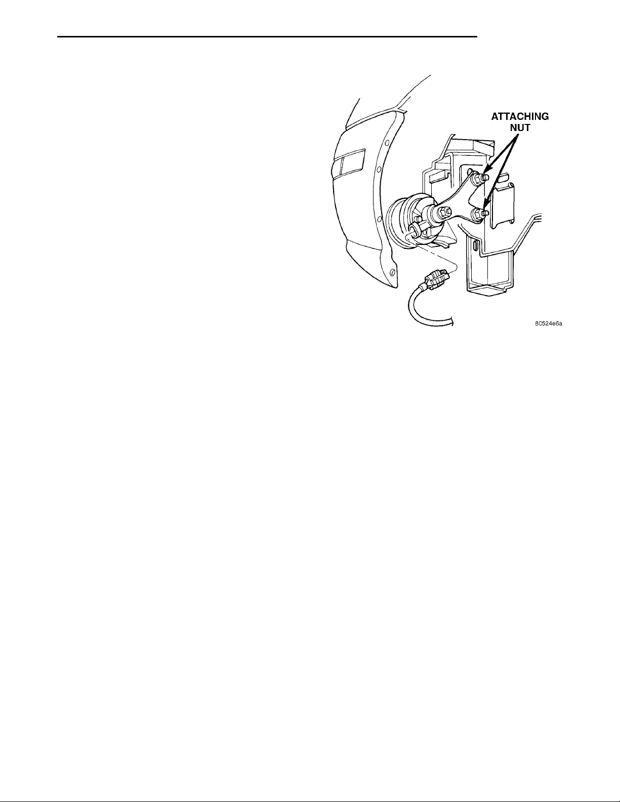
Disconnect connector and remove horn attaching
nuts from the bumper support bracket (Fig. 7).
INSTALLATION
For installation, reverse the above procedures.
Insure that the horn projector does not touch bumper
reinforcement or the sound output may be altered.
HORN RELAY
REMOVAL
(1) Remove the Power Distribution Center cover
and locate the horn relay.
(2) Remove the horn relay (Fig. 5).
INSTALLATION
For installation, reverse the above procedures.
HORN SWITCHES
The Horn Switch is part of the Driver Airbag Module. Refer to Driver Airbag Module Removal and
Installation procedures in Group 8M.
Fig. 7 Horn Location
Page 6

 Loading...