

Page 1

PL AUDIO SYSTEM 8F - 1
AUDIO SYSTEM
CONTENTS
page page
GENERAL INFORMATION
INTRODUCTION ........................ 1
DESCRIPTION AND OPERATION
INTERFERENCE ELIMINATION ............. 1
DIAGNOSIS AND TESTING
AUDIO DIAGNOSTIC TEST PROCEDURES .... 1
BENCH TEST FOR ANTENNA MALFUNCTION . . 7
GENERAL INFORMATION
INTRODUCTION
Operating instructions for the factory installed
audio systems can be found in the Owner’s Manual
provided with the vehicle.
The vehicles are equipped with an Interior (Ignition Off Draw) fuse in the Power Distribution Center
located in the engine compartment. After the Interior
(IOD) fuse or battery has been disconnected the clock
will require resetting.
NOTE: This group covers both Left-Hand Drive
(LHD) and Right-Hand Drive (RHD) versions of this
model. Whenever required and feasible, the RHD
versions of affected vehicle components have been
constructed as mirror-image of the LHD versions.
While most of the illustrations used in this group
represent only the LHD version, the diagnostic and
service procedures outlined can generally be
applied to either version. Exceptions to this rule
have been clearly identified as LHD, RHD, or Export
if a special illustration or procedure is required.
TESTING .............................. 7
REMOVAL AND INSTALLATION
ANTENNA ............................. 7
FRONT DOOR SPEAKER ................. 9
INSTRUMENT PANEL SPEAKER ............ 8
RADIO ................................ 8
REAR SHELF SPEAKER(S) ................ 9
to suppress ignition noise which may interfere with
radio reception.
• Left engine mount clip on strap
• Engine to shock tower reinforcement
Inductive type spark plug cables in the high tension circuit of the ignition system complete the interference suppression. Faulty or deteriorated spark
plug wires should be replaced.
DIAGNOSIS AND TESTING
AUDIO DIAGNOSTIC TEST PROCEDURES
CAUTION: The CD player will only operate between
approximate temperatures of -23°C and +65°C (-10°F
and +145°F).
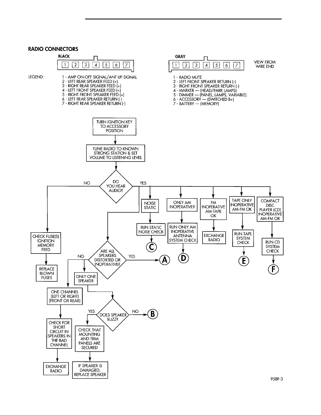
Whenever a radio malfunction occurs;
(1) First check FUSES:
(a) Power Distribution Center (PDC), Interior
lamp fuse, M1 - Radio Memory Feed
(b) Fuse Block:
(I) Fuse 12, Illumination in the fuse block
(II) Fuse 16, Ignition feed in the fuse block
DESCRIPTION AND OPERATION
INTERFERENCE ELIMINATION
The radio utilizes a ground wire plugged on to a
blade terminal and is bolted to the radio chassis.
Both connector and terminal should be securely
attached. The engine has two separate ground straps
NOTE: The vehicles are shipped with the INTERIOR
LAMP fuse disconnected.
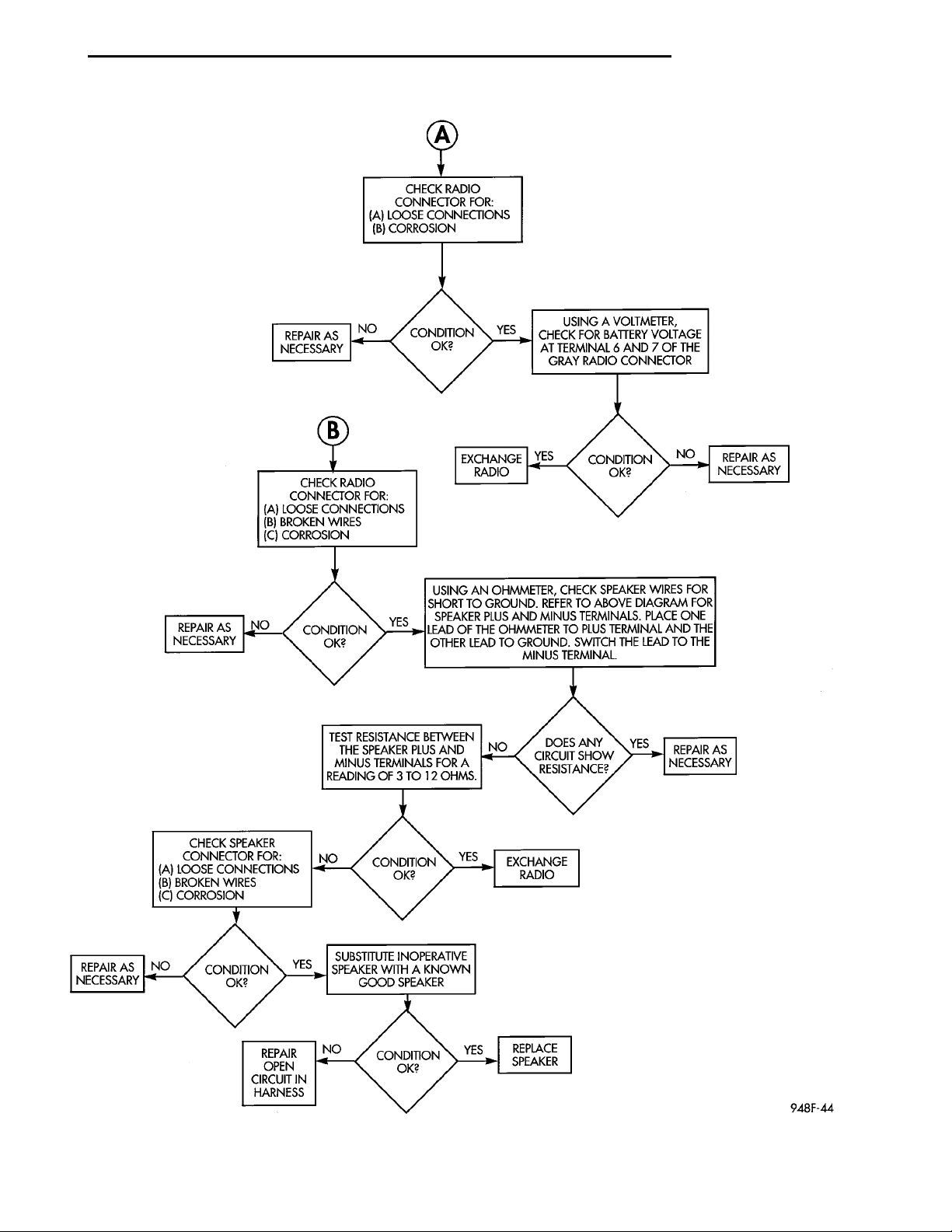
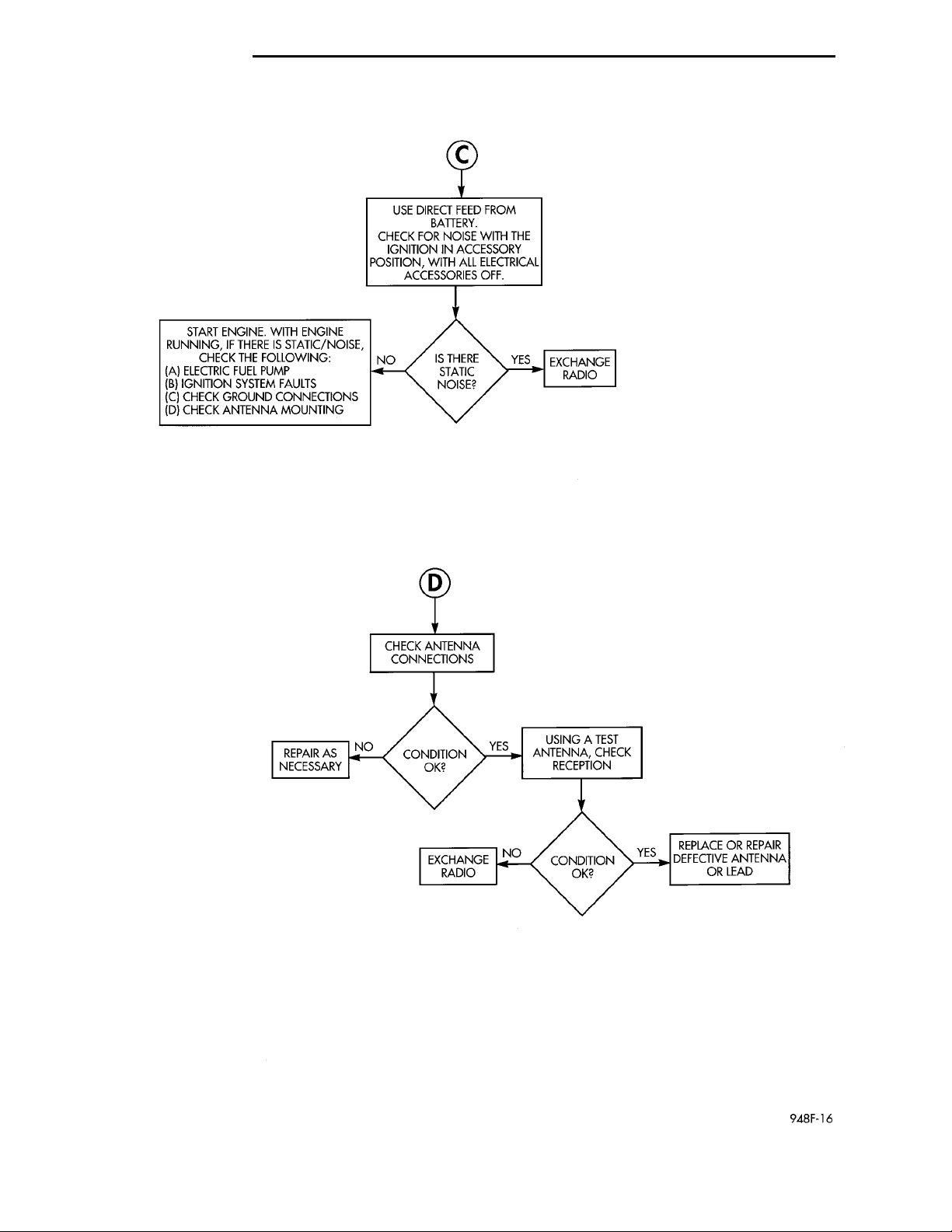
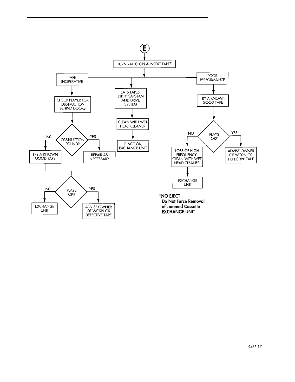
(2) Verify, the radio wire harness are properly connected before starting normal diagnosis and repair
procedures. Refer to Audio Diagnostic Charts and/or
Group 8W, Wiring Diagrams, Radio Section.
Page 2
RADIO CONNECTORS
BLACKLEGEND:1 - AMP ON-OFF SIGNAL/ANT UP SIGNAL2 - LEFT REAR SPEAKER FEED (+)3 - RIGHT REAR SPEAKER FEED (+)4 - LEFT FRONT SPEAKER FEED (+)5 - RIGHT FRONT SPEAKER FEED (+)6 - LEFT REAR SPEAKER RETURN (-)7 - RIGHT REAR SPEAKER RETURN (-) GRAY VIEW FROMWIRE END1 - RADIO MUTE2 - LEFT FRONT SPEAKER RETURN (-)3 - RIGHT FRONT SPEAKER RETURN (-)4 - MARKER - (HEAD/PARK LAMPS)5 - DIMMER - (PANEL LAMPS, VARIABLE)6 - ACCESSORY - (SWITCHED B+)7 - BATTERY - (MEMORY)TURN IGNITION KEY TOACCESSORY POSITIONTUNE RADIO TO KNOWN STRONGSTATION & SET VOLUME TO LISTEN-ING LEVELNOYESDO YOU HEAR AUDIO?NOISE STATICONLY AM INOPERATIVE?FM INOPERATIVE AM-TAPEOKTAPE ONLY INOPERATIVEAM-FM OKCOMPACT DISC PLAYER(CD) INOPERATIVE AM-FMOKRUN STATIC NOISE CHECKRUN ONLY AM INOPERATIVEANTENNA SYSTEM CHECKEXCHANGE RADIORUN TAPE SYSTEM CHECKRUN CD SYSTEM CHECKCHECK FUSE(S) IGNITIONMEMORY FEEDNOARE ALL SPEAKERS DIS-TORTED OR INOPERATIVE?YESREPLACE BLOWN FUSESONLY ONE SPEAKERONE CHANNEL (LEFT ORRIGHT) (FRONT OR REAR)CHECK FOR SHORT CIR-CUIT IN SPEAKERS IN THEBAD CHANNELYESDOES SPEAKER BUZZ?NOCHECK THAT MOUNTINGAND TRIM PANELS ARESECUREDEXCHANGE RADIOIF SPEAKER IS DAMAGED,REPLACE SPEAKER
8F - 2 AUDIO SYSTEM PL
DIAGNOSIS AND TESTING (Continued)
AM/FM STEREO – CD – CASSETTE TAPE
Page 3
CHECK RADIO CONNECTORFOR: (A) LOOSE CONNEC-TIONS (B) CORROSIONREPAIR ASNECESSARY NO CONDITIONOK? YES USING A VOLTMETER, CHECK FORBATTERY VOLTAGE AT TERMINAL 6AND 7 OF THE GRAY RADIO CON-NECTORCHECK RADIO CONNECTORFOR:A: LOOSE CONNECTIONSB: BROKEN WIRESC: CORROSION EXCHANGERADIO YESCONDITION OK?NOREPAIR AS NECESSARYREPAIR AS NECESSARYNOCONDITION OK?YESUSING AN OHMMETER,CHECK SPEAKER WIRESFOR SHORT TO GROUND.REFER TO ABOVE DIAGRAMFOR SPEAKER PLUS ANDMINUS TERMINALS. PLACEONE LEAD OF THE OHMME-TER TO PLUS TERMINALAND THE OTHER LEAD TOGROUND. SWITCH THELEAD TO THE MINUS TERMI-NAL.TEST RESISTANCEBETWEEN THE SPEAKERPLUS AND MINUS TERMI-NALS FOR A READING OF 3TO 12 OHMS.NODOES ANY CIRCUIT SHOWRESISTANCE?YESREPAIR AS NECESSARYCHECK SPEAKER CONNEC-TOR FOR:(A) LOOSE CONNECTIONS(B) BROKEN WIRES(C) CORROSIONNOCONDITION OK?YESEXCHANGE RADIOREPAIR AS NECESSARYNOCONDITION OK?YESSUBSTITUTE INOPERATIVESPEAKER WITH A KNOWNGOOD SPEAKERREPAIR OPEN CIRCUIT INHARNESSNOCONDITION OK?YESREPLACE SPEAKER
PL AUDIO SYSTEM 8F - 3
DIAGNOSIS AND TESTING (Continued)
AM/FM STEREO CONTINUED
Page 4
USE DIRECT FEED FROM BAT-TERY. CHECK FOR NOISE WITHTHE IGNITION IN ACCESSORYPOSITION, WITH ALL ELECTRI-CAL ACCESSORIES OFF.START ENGINE. WITH ENGINE RUNNING, IFTHERE IS STATIC/NOISE, CHECK THE FOL-LOWING:(A) ELECTRIC FUEL PUMP(B) IGNITION SYSTEM FAULTS(C) CHECK GROUND CONNECTIONS(D) CHECK ANTENNA MOUNTING NO IS THERESTATICNOISE? YES EXCHANGERADIOCHECK ANTENNACONNECTIONSREPAIR ASNECESSARY NO CONDITIONOK? YES USING A TESTANTENNA, CHECKRECEPTIONEXCHANGERADIO NO CONDI-TION OK? YES REPLACE OR REPAIRDEFECTIVE ANTENNAOR LEAD
8F - 4 AUDIO SYSTEM PL
DIAGNOSIS AND TESTING (Continued)
AM/FM STEREO CONTINUED
Page 5
NO YESOBSTRUCTION FOUND?IF NOT OK, EXCHANGE UNITTRY A KNOWN GOOD TAPEREPAIR AS NECESSARYNOYESPLAYS OK?EXCHANGE UNITADVISE OWNER OF WORNOR DEFECTIVE TAPENOYESPLAYS OK?LOSS OF HIGH FREQUENCY.CLEAN WITH WET HEADCLEANERADVISE OWNER OF WORNOR DEFECTIVE TAPEEXCHANGE UNIT*NO EJECTDo Not Force Removal ofJammed CassetteEXCHANGE UNIT
TURN RADIO ON & INSERT TAPE*TAPE INOPERA-TIVE POOR PERFOR-MANCECHECK PLAYER FOROBSTRUCTION BEHINDDOORS EATS TAPES.DIRTY CAPSTANAND DRIVE SYS-TEM
TRY A KNOWN GOODTAPECLEAN WITH WETHEAD CLEANER
PL AUDIO SYSTEM 8F - 5
DIAGNOSIS AND TESTING (Continued)
AM/FM STEREO CONTINUED
Page 6
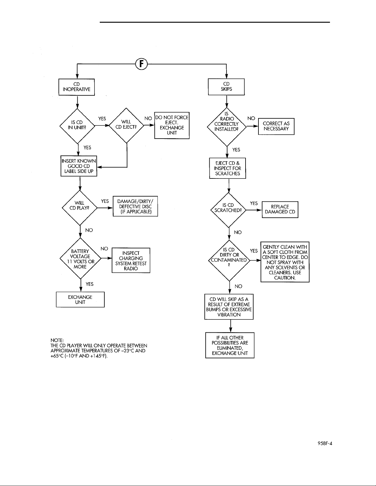
CD INOPERA-TIVE CD SKIPSIS CD IN UNIT? YES WILLCDEJECT? NO DONOTFORCEEJECT.EXCHANGEUNIT IS RADIO COR-RECTLYINSTALLED? NO CORRECTASNECESSARY YESYES INSERTKNOWNGOODCDLABELSIDEUPEJECT CD &INSPECT FORSCRATCHES WILL CD PLAY?YES DAMAGE/DIRTY/DEFECTIVEDISC(IFAPPLICABLE) NO BATTERYVOLTAGE 11VOLTS ORMORE NO INSPECTCHARGINGSYSTEMRETEST RADIOYESEXCHANGEUNITIS CDSCRATCHED? YES REPLACE DAM-AGED CD NO ISCDDIRTYORCONTAMINATED? YESGENTLYCLEANWITHASOFTCLOTHFROMCENTERTOEDGE.DONOTSPRAYWITHANYSOLVENTSORCLEANERS.USECAUTION. NOCD WILLSKIP AS ARESULT OFEXTREMEBUMPS OREXCESSIVEVIBRATION IF ALL OTHER POS-SIBILITIES AREELIMINATED,EXCHANGE UNITNOTE:THE CD PLAYER WILLONLY OPERATEBETWEEN APPROXI-MATE TEMPERATURESOF -23°C AND +65°C(-10°F AND +145°F).
8F - 6 AUDIO SYSTEM PL
DIAGNOSIS AND TESTING (Continued)
AM/FM STEREO CONTINUED
Page 7
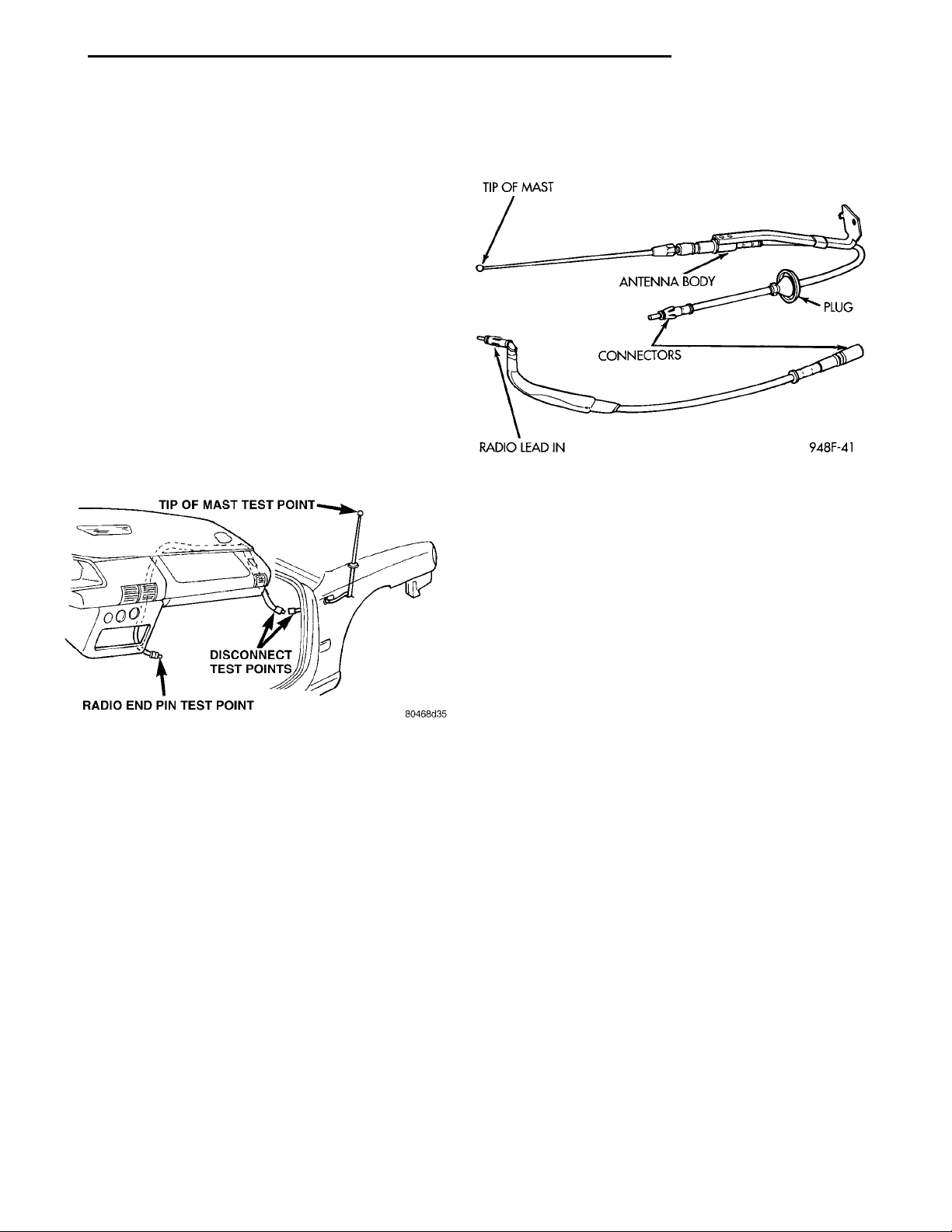
TIP OF MASTTEST POINTDISCONNECT TESTPOINTSRADIO END PIN TEST POINT
PL AUDIO SYSTEM 8F - 7
DIAGNOSIS AND TESTING (Continued)
TIP OF MAST ANTENNA BODY PLUGCONNECTORSRADIO LEAD IN
TESTING
The antenna has a short cable which connects into
the instrument panel harness. The connection is
made on the right side of the instrument panel.
Antenna performance may be tested by substituting a known good antenna. It is also possible to
check short or open circuits with an ohmmeter or
continuity light once the antenna cable is disconnected from the radio as follows:
(1) Continuity should be present between the
antenna mast and radio end pin of antenna cable
plug (Fig. 1).
(2) No continuity should be observed or a very
high resistance of several megohms between the
ground shell of the connector and radio end pin.
(3) Continuity should be observed between the
ground shell of the connector and the mounting hardware on the vehicle antenna. The wheel well splash
shield must be removed for access to the antenna
that is mounted on load beam.
bracket. Wiggle cable over its entire length to
reveal intermittent short or open circuits during step 1, 2 and 3.
Fig. 2 Antenna Bench Test Points
REMOVAL AND INSTALLATION
ANTENNA
Fig. 1 Antenna Test Points
BENCH TEST FOR ANTENNA MALFUNCTION
It is also possible to check short or open circuits
with an ohmmeter or continuity light once the
antenna has been removed from the vehicle.
(1) Continuity should be present between the tip of
the mast and radio lead in (Fig. 2).
(2) No continuity should be observed or a very
high resistance of several megohms between the
ground shell of the connector and radio end pin.
(3) Continuity should be observed between the
ground shell of the connector and the mounting
REMOVAL
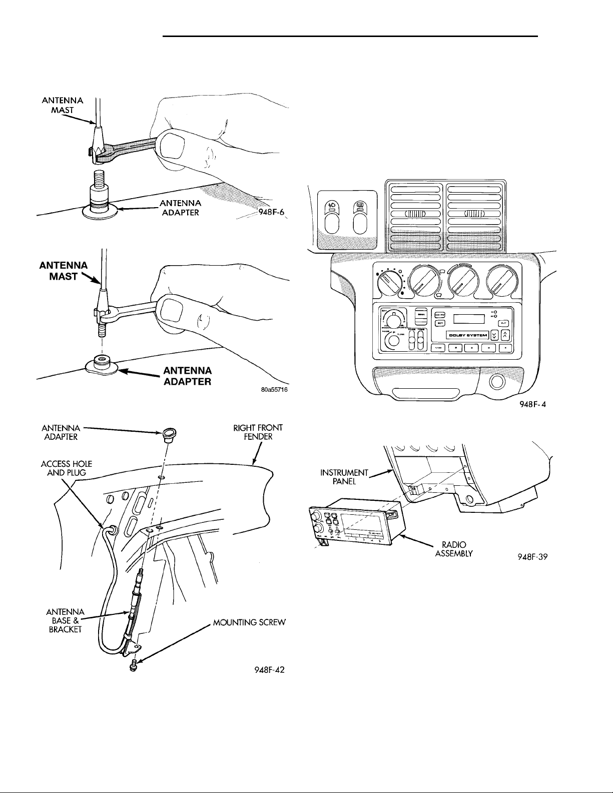
(1) Remove antenna mast by unscrewing mast
from antenna body (Fig. 3), or (Fig. 4).
(2) Locate the antenna lead disconnect in the
instrument panel wire harness above the right kick
panel. Disconnect the antenna cable from cable lead.
(3) Unfasten push pins from the rear of the plastic
inner fender shield and move shield to gain access to
mounting screws (Fig. 5).
(4) Remove mounting screw and remove antenna
base and cable assembly from under the fender.
INSTALLATION
(1) Align antenna adapter tongue with grove in
the fender hole and push adapter into fender.
(2) From under the fender, push the antenna base
and cable assembly through the adapter in the
fender. Tighten mounting screw to 7 N·m (75 in. lbs.).
(3) Seat the grommet in the side panel and connect the cable to the instrument panel harness connector.
(4) Install the plastic inner fender shield.
Page 8
ANTENNA MAST ANTENNAADAPTER
ANTENNAADAPTER RIGHT FRONTFENDERMOUNTINGSCREWANTENNA BASE &BRACKET ACCESS HOLE ANDPLUG
ANTENNA MASTANTENNA ADAPTER
8F - 8 AUDIO SYSTEM PL
REMOVAL AND INSTALLATION (Continued)
(5) Connect the antenna cable to the cable lead.
Fig. 3 Antenna Mast Removal
(2) Remove two mounting screws on the radio and
pull out of instrument panel (Fig. 7).
INSTRUMENTPANEL RADIO ASSEMBLY
(3) Disconnect wiring and antenna cable and
remove ground wire from radio.
INSTALLATION
For installation reverse the above procedures.
RADIO
Fig. 4 Antenna Mast Removal - Export
Fig. 6 Center Module Bezel
Fig. 7 Radio Assembly
INSTRUMENT PANEL SPEAKER
REMOVAL
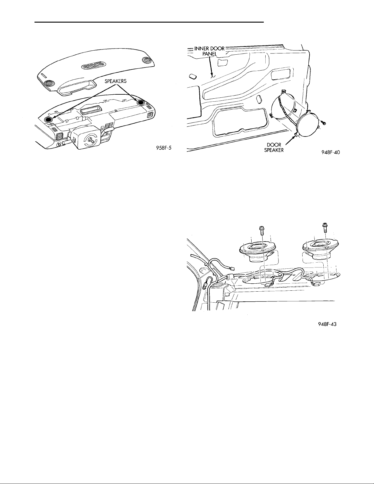
(1) Remove instrument panel top cover and cluster
bezel (Fig. 8). Refer to Group 8E, Instrument Panel
and Systems, for removal procedures.
(2) Remove speaker retaining screws.
(3) Remove speaker and disconnect wire connector.
Fig. 5 Antenna Mounting
INSTALLATION
For installation reverse the above procedures.
REMOVAL
(1) Remove center module bezel (Fig. 6).
Page 9
SPEAKERS
PL AUDIO SYSTEM 8F - 9
REMOVAL AND INSTALLATION (Continued)
Fig. 8 Instrument Panel Speakers
FRONT DOOR SPEAKER
REMOVAL
(1) Remove door trim panel, refer to Group 23,
Body.
(2) Remove three speaker retaining screws (Fig. 9).
(3) Remove speaker assembly and disconnect wire
connector.
INSTALLATION
For installation reverse the above procedures.
REAR SHELF SPEAKER(S)
REMOVAL
(1) Remove rear seat and seat back, refer to Group
23, Body for seat removal procedures. Remove seat
cushion, seat back and seat belt anchor bolts.
(2) Pry out the seat belt trim bezel along the rearward edge.
(3) Partially remove the shelf trim panel slipping
it down to the seat back position.
(4) Remove four speaker retaining screws (Fig. 10).
(5) Remove speaker and disconnect wire connector.
Fig. 9 Front Door Speaker
INSTALLATION
For installation reverse the above procedures. Position speakers so that the wire connectors are pointing to the drivers side of car. Tighten the seat belt
anchor bolts to the proper torque refer to Group 23,
Body.
Fig. 10 Rear Shelf Speakers
Page 10

 Loading...