

Page 1
PL INSTRUMENT PANEL AND SYSTEMS 8E - 1
INSTRUMENT PANEL AND SYSTEMS
CONTENTS
page page
DIAGNOSIS AND TESTING
FOG LAMP SWITCH TEST ................ 1
HEADLAMP LEVELING SWITCH ........... 1
INSTRUMENT PANEL AND COMPONENTS . . . 2
REMOVAL AND INSTALLATION
ENDCAPRHD ......................... 2
DIAGNOSIS AND TESTING
FOG LAMP SWITCH TEST
Refer to Group 8W, Wiring Diagrams for wiring or
circuit information.
FRONT
(1) Remove the fog lamp switch and disconnect the
connector at the center stack.
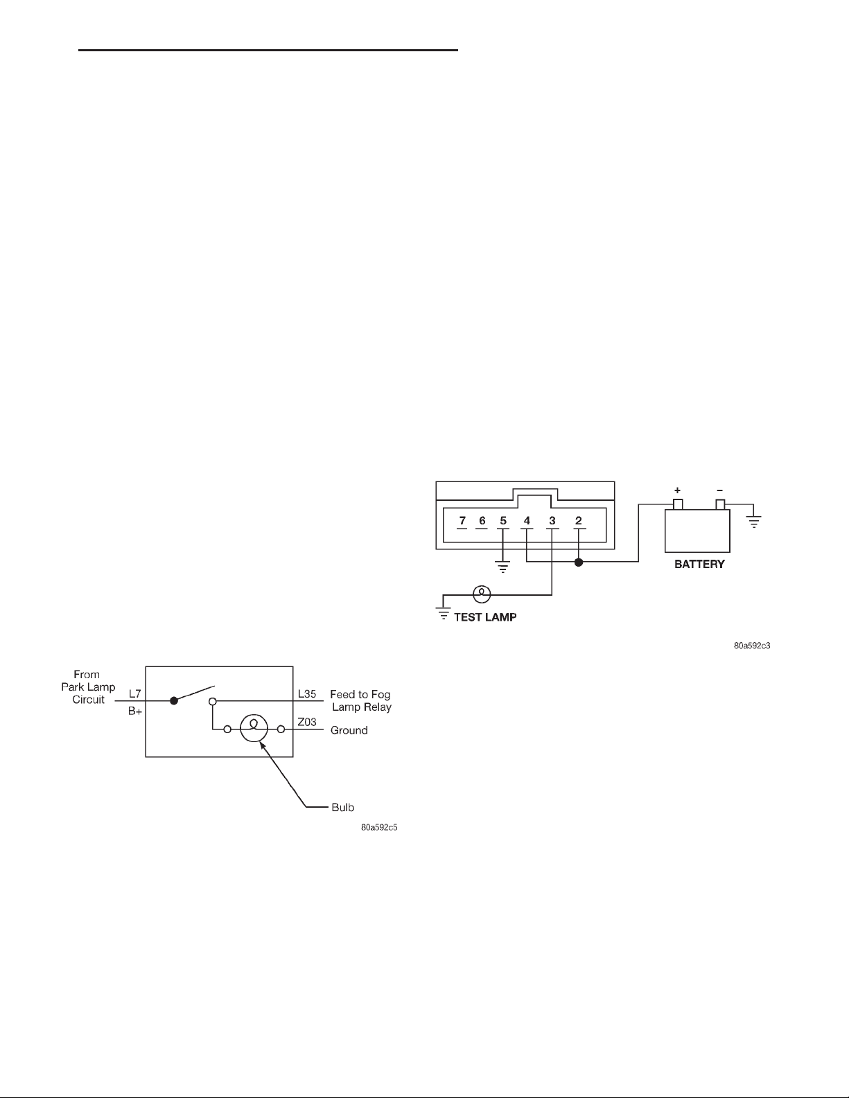
(2) Using two jumper wires connect Pin L7 to bat-
tery voltage, and connect Pin Z03 to ground (Fig. 1).
(3) Push the fog lamp switch button. The LED
indicator on the front of the switch should illuminate.
Check Pin L35 with a test lamp for battery voltage.
(4) If either the LED or the test lamp fails to illuminate, replace the switch.
FRONT FOG LAMP SWITCH .............. 2
HEADLAMP LEVELING SWITCH ........... 3
REAR WINDOW DEFOGGER AND/OR REAR
FOG LAMP SWITCH ................... 3
(4) Push the fog lamp switch button. The test lamp
should illuminate, and the LED indicator on the
front of the switch.
(5) If either the LED, or the test lamp fails to illuminate, replace the switch.
Fig. 1 Front Fog Lamp Switch Circuit Diagram
REAR
(1) Remove the fog lamp switch. Refer to Rear
Window Defogger and/or Fog Lamp Switch Removal.
(2) Using two jumper wires connect Pin 2 and Pin
4 of the switch to battery voltage.
(3) Using a test lamp, connect the test lamp to Pin
3 as shown in (Fig. 2). Refer to Group 8W, Wiring
Diagrams for fog lamp switch circuit.
Fig. 2 Rear Fog Lamp Switch Test
HEADLAMP LEVELING SWITCH
(1) Remove the headlamp leveling switch from the
instrument panel and disconnect the wire harness
connector from the switch. Refer to Wiring Diagrams
for the proper wire circuits and the wire connector
connections.
(2) If the L.E.D. is not illuminated, using a voltmeter, connect B+ lead to Pin 4 of the Wire harness connector. Connect the negative lead to Pin 3. Turn ON
the headlamp switch to the low beam position and
ensure the instrument panel dimmer switch is on
day light driving position. If voltage is present,
replace switch. If no voltage, connect the ground lead
to a good ground, if voltage, repair Pin 3 ground circuit as necessary, and if no voltage, refer to Wiring
Diagrams and test circuit back to headlamp switch.
(3) Using a voltmeter, connect B+ lead to Pin 2 of
the Wire harness connector. Connect the negative
lead to Pin 3. Turn ON the headlamp switch to the
low beam position. If battery voltage, go to Step 5. If
not OK, go to Step 4.
Page 2
8E - 2 INSTRUMENT PANEL AND SYSTEMS PL
DIAGNOSIS AND TESTING (Continued)
(4) Connect the ground lead to a good ground, if no
voltage, refer to Wiring Diagrams and test circuit
back to headlamp switch. If battery voltage, repair
Pin 3 ground circuit as necessary.
(5) Turn headlamps OFF. Connect the wire harness connector to the headlamp leveling switch. Turn
ON the headlamp switch to the low beam position.
Check voltage at Pin 5, while rotating the headlamp
leveling switch knob through the four positions. The
voltage reading should change as the switch is
rotated to each position. If the voltage does not vary
replace switch. If OK, test the headlamp leveling
motors and/or circuit to the motors.
(3) Remove the end cap
Installation
For installation, reverse the above procedures.
FRONT FOG LAMP SWITCH
REMOVAL
(1) Disconnect the wire connector in the center
stack, BUX left side and RHD right side.
(2) Remove the floor console and disconnect the
two clips attaching the wire harness from the underside of the floor console.
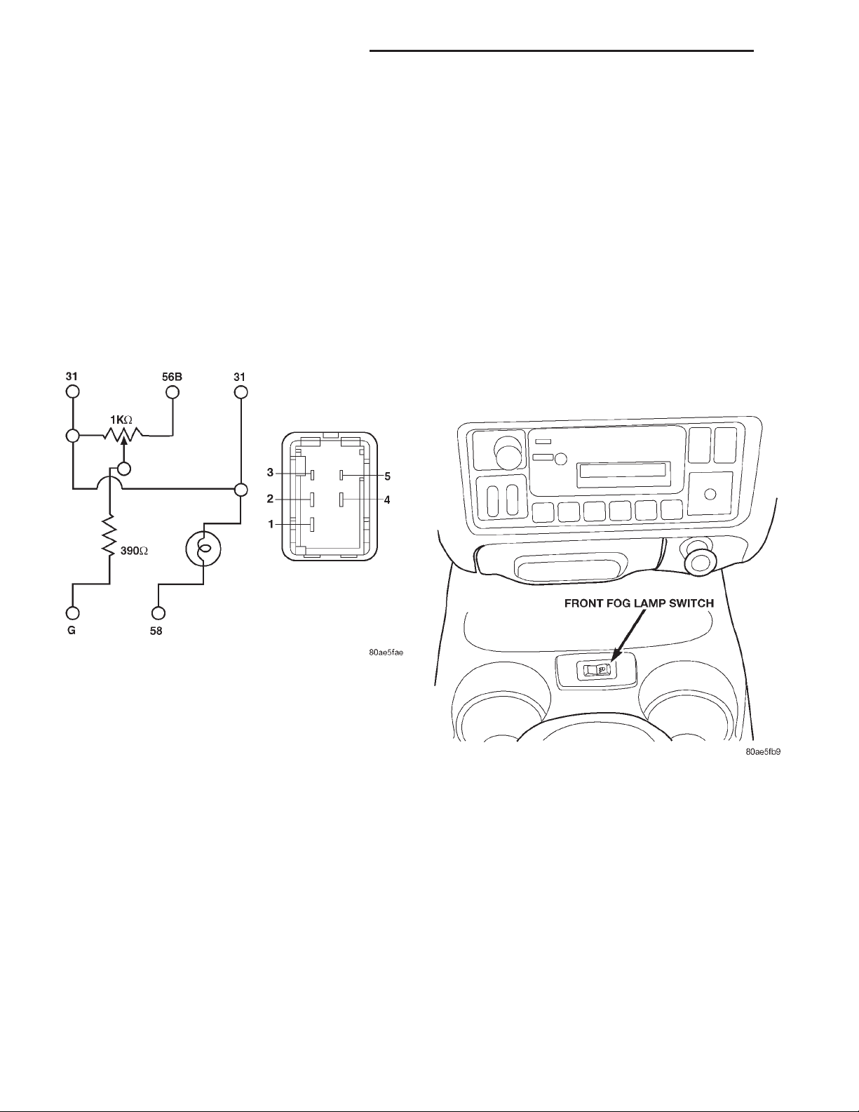
(3) Remove the switch bezel and wiring harness
assembly from the floor console (Fig. 4).
INSTALLATION
For installation, reverse the above procedures.
Fig. 3 Headlamp Leveling Switch Circuit Diagram
INSTRUMENT PANEL AND COMPONENTS
CAUTION: Disconnect the battery negative cable
before servicing the instrument panel or components. When power is required for test purposes,
connect battery cable for test only. Disconnect the
battery negative cable after test and before continuing service procedures.
REMOVAL AND INSTALLATION
END CAP RHD
Removal
(1) Unlatch the glove box door and lower is to the
full open position.
(2) Remove the left trim panel as necessary to
remove the end cap attaching screws.
Fig. 4 Front Fog Lamp Switch
Page 3
PL INSTRUMENT PANEL AND SYSTEMS 8E - 3
REMOVAL AND INSTALLATION (Continued)
HEADLAMP LEVELING SWITCH
REMOVAL
(1) Remove the top cover and cluster bezel assem-
bly.
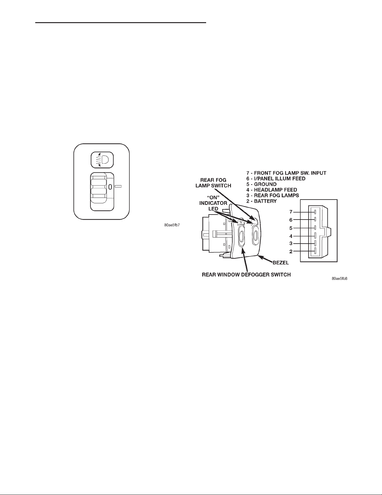
(2) Disengage the headlamp leveling switch bezel
from instrument panel (Fig. 5).
(3) Pull the switch and bezel rearward from the
opening and disconnect the wire connector.
INSTALLATION
For installation, reverse the above procedures.
REAR WINDOW DEFOGGER AND/OR REAR FOG LAMP SWITCH
REMOVAL
(1) Remove the top cover and cluster bezel assembly. Refer to Top Cover and Cluster Bezel Removal
above.
(2) Reach in and disengage the bezel latches and
remove the switch assembly (Fig. 6).
(3) Pull the bezel and switch(s) rearward from the
opening and disconnect the wire connector(s).
(4) If either switch is defective, replace the entire
switch assembly.
INSTALLATION
For installation, reverse the above procedures.
Fig. 5 Headlamp Leveling Switch
Fig. 6 Rear Window Defogger and Rear Fog Lamp
Switch
Page 4

 Loading...