

Page 1

PL INSTRUMENT PANEL AND SYSTEMS 8E - 1
INSTRUMENT PANEL AND SYSTEMS
CONTENTS
page page
GENERAL INFORMATION
INTRODUCTION ........................ 1
DESCRIPTION AND OPERATION
DOME LAMP ........................... 2
ELECTRONIC DIGITAL CLOCK ............. 2
INSTRUMENT CLUSTER .................. 2
WARNING AND INDICATOR LAMPS ......... 2
DIAGNOSIS AND TESTING
AIRBAG WARNING SYSTEM ............... 2
BRAKE SYSTEM WARNING LAMP TEST ...... 2
FOG LAMP SWITCH TEST EXPORT ......... 3
FOG LAMP SWITCH TEST ................. 3
FUEL TANK SENDING UNIT TEST ........... 3
HEADLAMP LEVELING SWITCH ............ 3
HEADLAMP SWITCH TEST ................ 4
HEATER A/C BLOWER SWITCH TEST ........ 4
HEATER BLOWER SWITCH TEST ........... 4
INDIVIDUAL GAUGE INOPERATIVE .......... 6
INSTRUMENT PANEL AND COMPONENTS .... 5
LOW OIL PRESSURE WARNING LAMP TEST . . 5
MULTIPLE GAUGE INOPERATIVE TEST ...... 5
SEAT BELT REMINDER SYSTEM TEST ....... 7
SENDING UNIT ......................... 7
SERVICE ENGINE SOON INDICATOR ........ 7
VEHICLE SPEED SENSOR TEST ........... 7
REMOVAL AND INSTALLATION
ASH RECEIVER RETAINER AND LAMP ....... 8
CENTER BEZEL ........................ 8
CIGAR LIGHTER RECEPTACLE ............. 8
CLUSTER LAMP ........................ 8
CLUSTER PRINTED CIRCUIT BOARD ........ 9
CLUSTER ............................. 8
DOME LENS/LAMP ...................... 9
ENDCAPRHD ......................... 9
FLOOR CONSOLE ....................... 9
FRONT FOG LAMP SWITCH EXPORT ........ 9
GAUGE .............................. 10
GLOVE BOX DOOR/BIN .................. 10
GLOVE BOX SWITCH/LAMP .............. 10
HEADLAMP LEVELING SWITCH EXPORT .... 10
HEADLAMP SWITCH .................... 10
HEATER A/C CONTROL BLOWER SWITCH . . . 11
HEATER A/C CONTROL LAMP ............. 11
HEATER A/C CONTROL .................. 11
HEATER CONTROL BLOWER SWITCH ...... 11
IGNITION KEY LAMP .................... 11
INSTRUMENT PANEL ................... 12
LEFT TRIM PANEL ...................... 14
ODOMETER ........................... 14
RADIO ............................... 14
REAR WINDOW DEFOGGER AND/OR FOG
LAMP SWITCH ....................... 14
REAR WINDOW DEFOGGER AND/OR REAR
FOG LAMP SWITCH EXPORT ............ 15
RIGHT TRIM PANEL ..................... 15
SHIFTER KNOB ........................ 15
STEERING COLUMN COVER LINER ........ 15
STEERING COLUMN COVER ............. 15
STEERING COLUMN SHROUDS ........... 16
TOP COVER AND CLUSTER BEZEL
REMOVAL ........................... 16
TRANSMISSION RANGE INDICATOR LAMP . . 16
TRUNK LAMP/LENS ..................... 17
VEHICLE SPEED SENSOR ............... 17
GENERAL INFORMATION
INTRODUCTION
The purpose of the dash gauges and indicator
lamps is to keep the driver informed about the operating condition of the vehicle. If an abnormal condition occurs, the driver is informed by indicator lamp.
The driver can seek service before damage occurs.
Indicator lamps use ON/OFF switch functions for
operation, while gauges use a sending unit or sensor.
Page 2
8E - 2 INSTRUMENT PANEL AND SYSTEMS PL
GENERAL INFORMATION (Continued)
NOTE: This group covers both Left-Hand Drive
(LHD) and Right-Hand Drive (RHD) versions of this
model. Whenever required and feasible, the RHD
versions of affected vehicle components have been
constructed as mirror-image of the LHD versions.
While most of the illustrations used in this group
represent only the LHD version, the diagnostic and
service procedures outlined can generally be
applied to either version. Exceptions to this rule
have been clearly identified as LHD, RHD, or Export
if a special illustration or procedure is required.
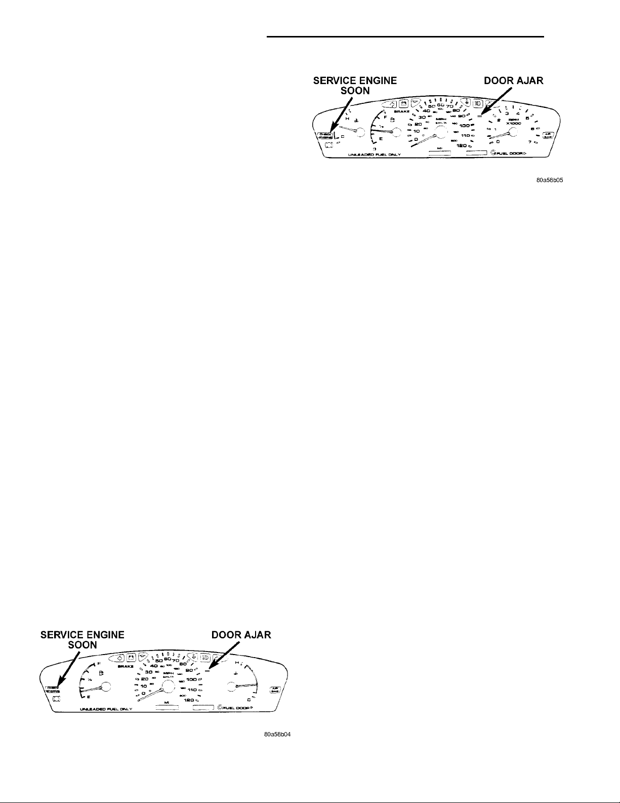
Fig. 2 Instrument Cluster Without Tachometer
WARNING AND INDICATOR LAMPS
DESCRIPTION AND OPERATION
SERVICE ENGINE SOONDOOR AJAR
DOME LAMP
The Dome Lamp operates when a door is open or
when the headlamp switch is placed in courtesy position.
ELECTRONIC DIGITAL CLOCK
The electronic digital clock is in the radio. The
clock and radio each use the display panel built into
the radio. A digital readout indicates the time in
hours and minutes whenever the ignition switch is in
the ON or ACC position.
When the ignition switch is in the OFF position, or
when the radio frequency is being displayed, time
keeping is accurately maintained.
The procedure for setting the clock varies slightly
with each radio. The correct procedure is described in
the individual radio operating instructions. Refer to
the Owner’s Manual supplied with the vehicle.
INSTRUMENT CLUSTER
There are two conventional instrument cluster
assemblies available. The clusters electronically drive
the speedometer, odometer, and gauges (Fig. 1) and
(Fig. 2).
GAUGES
All gauges in the electronic clusters are the analog
type gauges. When the ignition switch is moved to
the OFF position, the cluster drives each gauge to its
lowest position.
The instrument cluster has warning lamps and
indicators for the following systems:
• Airbag
• Anti-lock Brakes (ABS) if equipped
• Brake warning
• Charging System
• Door Ajar
• High beam indicator
• Low oil pressure
• Malfunction indicator (check engine) lamp
• Right and left turn signals.
• Seat belt warning
DIAGNOSIS AND TESTING
AIRBAG WARNING SYSTEM
For testing of this system refer to Group 8M,
Restraint Systems.
BRAKE SYSTEM WARNING LAMP TEST
The brake warning lamp illuminates when the
parking brake is applied with ignition switch turned
to the ON position. The same lamp will also illuminate if one of the two service brake systems fail the
when brake pedal is applied.
To test the system:
• As the ignition switch is turned to the start posi-
tion the lamp should light.
• Turn ignition switch to the ON position and
apply the parking brake. The lamp should light.
If lamp fails to light inspect for:
• A burned out lamp
• Loose, corroded or damaged socket
• A damaged circuit board
• A broken or disconnected wire at the switch
• Defective switch
To test the service brake warning system, refer to
Group 5, Brakes, Hydraulic System Control Valves.
Fig. 1 Instrument Cluster With Tachometer
Page 3
PL INSTRUMENT PANEL AND SYSTEMS 8E - 3
DIAGNOSIS AND TESTING (Continued)
FOG LAMP SWITCH TEST
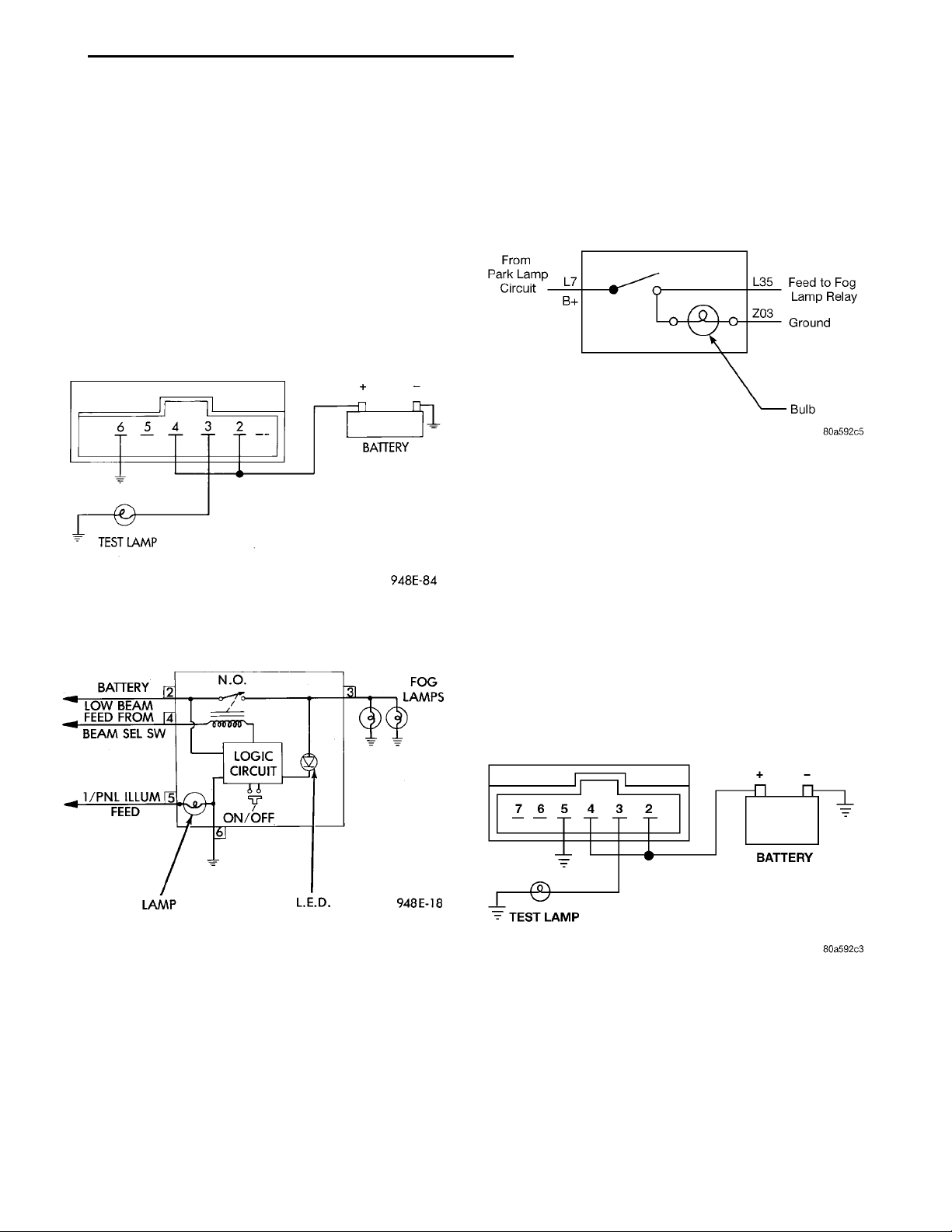
(1) Remove the fog lamp switch. Refer to the Rear
Window Defogger and/or Fog Lamp Switch Removal.
(2) Using two jumper wires, connect Pin 2 and Pin
4 of the switch to battery voltage.
(3) Using a test lamp, connect the test lamp to Pin
3 as shown in (Fig. 3). Refer to (Fig. 4) for fog lamp
switch circuit.
BATTERY
BEAM SEL SW
(4) Push the fog lamp switch button. The test lamp
LOW BEAM FEED FROM
1/PNL ILLUM FEED
LAMP L.E.D. FOG LAMPSN.O.
LOGICCIR-CUIT
ON/OFF
and the LED indicator on the front of the switch
should illuminate.
(5) If either the LED or the test lamp fails to illuminate, replace the switch.
Fig. 3 Fog Lamp Switch Test
BATTERYTEST LAMP
(3) Push the fog lamp switch button. The LED
indicator on the front of the switch should illuminate.
Check Pin L35 with a test lamp for battery voltage.
(4) If either the LED or the test lamp fails to illuminate, replace the switch.
TEST LAMPBATTERY
Fig. 5 Front Fog Lamp Switch Circuit Diagram
REAR EXPORT
(1) Remove the fog lamp switch. Refer to Rear
Window Defogger and/or Fog Lamp Switch Removal.
(2) Using two jumper wires connect Pin 2 and Pin
4 of the switch to battery voltage.
(3) Using a test lamp, connect the test lamp to Pin
3 as shown in (Fig. 6). Refer to Group 8W, Wiring
Diagrams for fog lamp switch circuit.
(4) Push the fog lamp switch button. The test lamp
should illuminate, and the LED indicator on the
front of the switch.
(5) If either the LED, or the test lamp fails to illuminate, replace the switch.
Fig. 4 Fog Lamp Switch Circuit
FOG LAMP SWITCH TEST EXPORT
Refer to Group 8W, Wiring Diagrams for wiring or
circuit information.
FRONT EXPORT
(1) Remove the fog lamp switch and disconnect the
connector at the center stack.
(2) Using two jumper wires connect Pin L7 to bat-
tery voltage, and connect Pin Z03 to ground (Fig. 5).
Fig. 6 Rear Fog Lamp Switch Test
FUEL TANK SENDING UNIT TEST
Refer to Group 14, Fuel for test procedures.
HEADLAMP LEVELING SWITCH
(1) Remove the headlamp leveling switch from the
instrument panel and disconnect the wire harness
connector from the switch. Refer to Wiring Diagrams
for the proper wire circuits and the wire connector
connections.
Page 4
8OFF’ POSITION 8PARK’ POSITION8ON’ POSITION
8E - 4 INSTRUMENT PANEL AND SYSTEMS PL
DIAGNOSIS AND TESTING (Continued)
(2) If the L.E.D. is not illuminated, using a voltmeter, connect B+ lead to Pin 4 of the Wire harness connector. Connect the negative lead to Pin 3. Turn ON
the headlamp switch to the low beam position and
ensure the instrument panel dimmer switch is on
day light driving position. If voltage is present,
replace switch. If no voltage, connect the ground lead
to a good ground, if voltage, repair Pin 3 ground circuit as necessary, and if no voltage, refer to Wiring
Diagrams and test circuit back to headlamp switch.
(3) Using a voltmeter, connect B+ lead to Pin 2 of
the Wire harness connector. Connect the negative
lead to Pin 3. Turn ON the headlamp switch to the
low beam position. If battery voltage, go to Step 5. If
not OK, go to Step 4.
(4) Connect the ground lead to a good ground, if no
voltage, refer to Wiring Diagrams and test circuit
back to headlamp switch. If battery voltage, repair
Pin 3 ground circuit as necessary.
(5) Turn headlamps OFF. Connect the wire harness connector to the headlamp leveling switch. Turn
ON the headlamp switch to the low beam position.
Check voltage at Pin 5, while rotating the headlamp
leveling switch knob through the four positions. The
voltage reading should change as the switch is
rotated to each position. If the voltage does not vary
replace switch. If OK, test the headlamp leveling
motors and/or circuit to the motors.
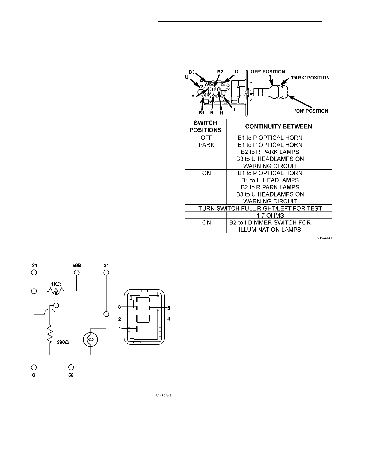
(2) Use a ohmmeter, and check continuity between
the terminals of the switch as shown in the Headlamp Switch Test (Fig. 8).
Fig. 7 Headlamp Leveling Switch Circuit Diagram
HEADLAMP SWITCH TEST
(1) Remove the headlamp switch. Refer to Head-
lamp Switch Removal.
Fig. 8 Headlamp Switch Test
HEATER A/C BLOWER SWITCH TEST
(1) Remove Heater A/C control module. Refer to
Heater A/C Control Removal procedures.
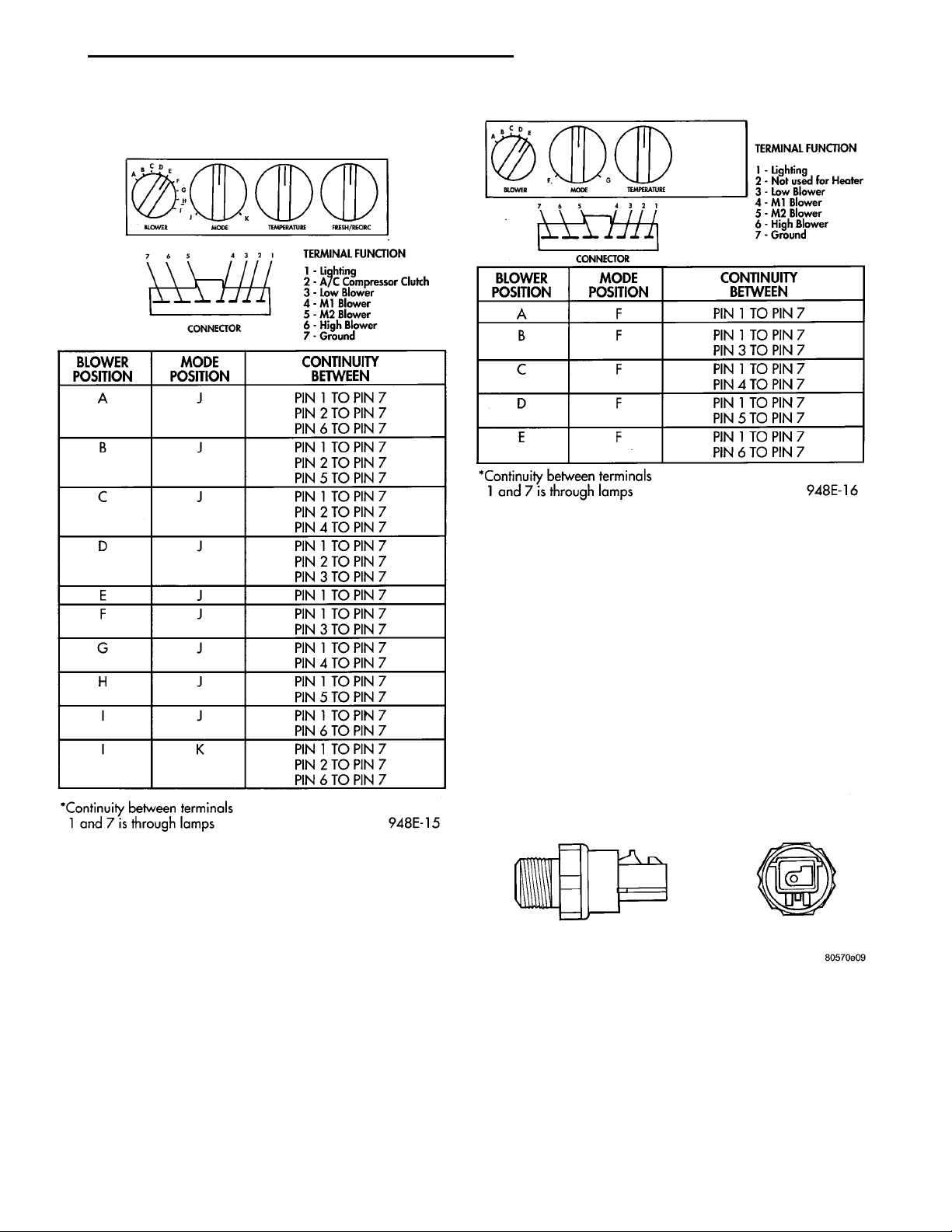
(2) Use a ohmmeter, and check continuity between
the terminals of the switch as shown in the Blower
Switch Test (Fig. 9).
(3) If the switch fails any part of the continuity
test, other then Pin 1 to Pin 7, replace Heater A/C
Control. If no continuity between Pin 1 to Pin 7
check the lamps, replace if necessary.
HEATER BLOWER SWITCH TEST
(1) Remove heater control, refer to A/C Heater
Control Removal.
(2) Use a ohmmeter, and check continuity between
the terminals of the switch as shown in the Heater
Blower Test (Fig. 10).
(3) If switch fails any part of the continuity test,
other then Pin 1 to Pin 7, replace heater control. If
no continuity between Pin 1 to Pin 7 check the
lamps, replace if necessary.
Page 5
TERMINAL FUNCTION1 — Lighting2 — A/C Compressor Clutch3 — Low Blower4 — M1 Blower5 — M2 Blower6 — High Blower7 — GroundCONNECTOR
PL INSTRUMENT PANEL AND SYSTEMS 8E - 5
CONNECTOR
TERMINAL FUNCTION
1 — Lighting
2 — Not used for Heater
3 — Low Blower
4 — M1 Blower
5 — M2 Flower
6 — High Blower
7 — Ground
DIAGNOSIS AND TESTING (Continued)
Fig. 9 Blower Switch Test
INSTRUMENT PANEL AND COMPONENTS
CAUTION: Disconnect the battery negative cable
before servicing the instrument panel or components. When power is required for test purposes,
connect battery cable for test only. Disconnect the
battery negative cable after test and before continuing service procedures.
LOW OIL PRESSURE WARNING LAMP TEST
The low oil pressure warning lamp will illuminate
when the ignition switch is turned to the ON position
without engine running. The lamp also illuminates if
Fig. 10 Heater Blower Switch Test
the engine oil pressure drops below a safe oil pressure level.
To test the system, turn the ignition switch to the
ON position. If the lamp fails to light, inspect for a
broken or disconnected wire at the oil pressure
switch, located at the front of the engine (Fig. 11). If
the wire at the connector checks good, pull the connector loose from the switch and with a jumper wire,
ground the connector to the engine. With the ignition
switch turned to the ON position, check the warning
lamp. If the lamp still fails to light, inspect for a
burned out lamp or disconnected socket in the cluster.
Fig. 11 Oil Pressure Switch
MULTIPLE GAUGE INOPERATIVE TEST
Test speedometer, tachometer and other gauges for
malfunction:
(1) Remove the cluster. Refer to Cluster Removal
and Installation.
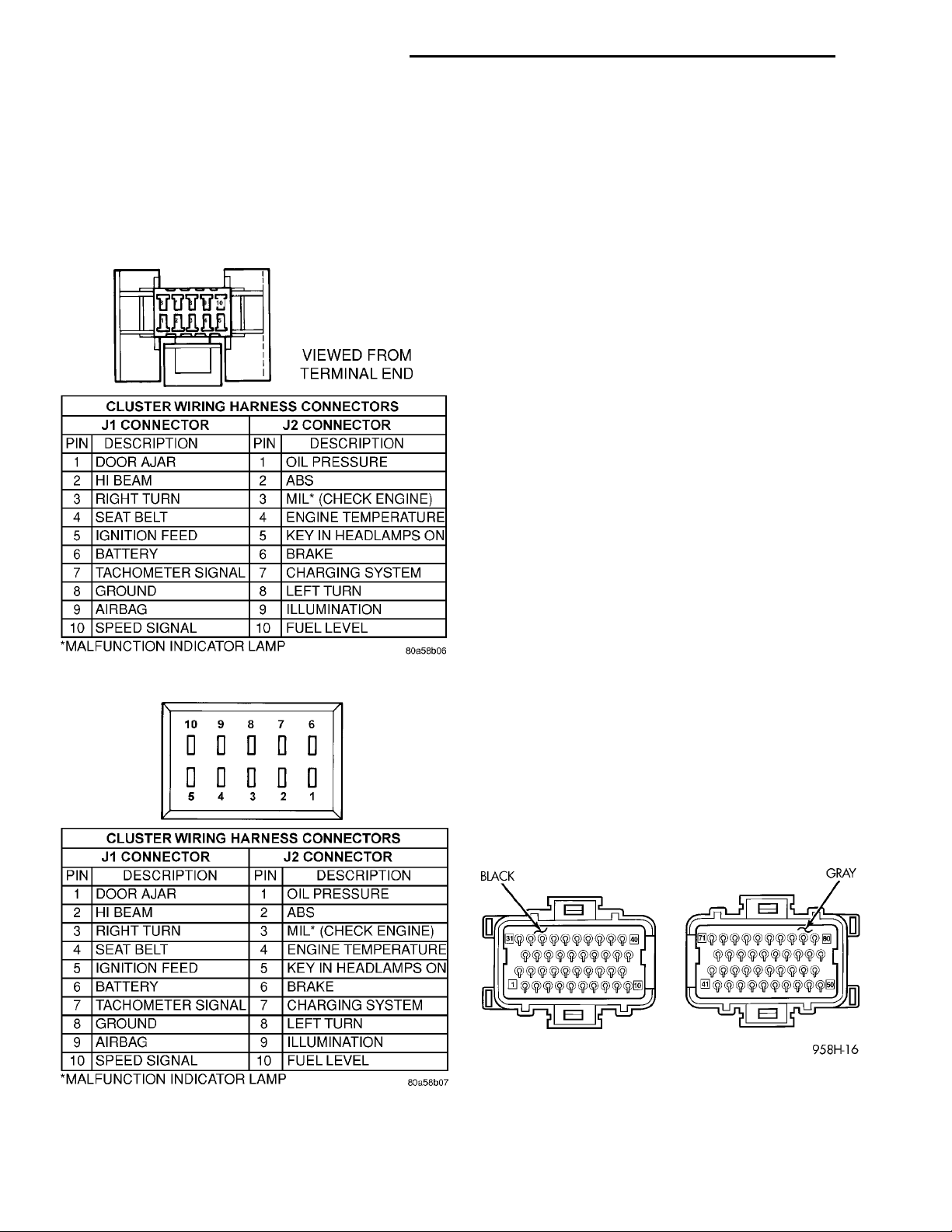
(2) Check for ignition voltage at Pin J1-5 of the
cluster wire harness connector (Fig. 12) and (Fig. 13).
Page 6
VIEWED FROM TERMINALEND
8E - 6 INSTRUMENT PANEL AND SYSTEMS PL
DIAGNOSIS AND TESTING (Continued)
Check for battery voltage at Pin J1-6 of the connector. If no voltage, repair as necessary.
(3) Check Pin J1-8 of the connector for continuity
to ground. If no ground, repair as necessary.
(4) If the voltage and ground are OK, and the pins
or the connectors are not distorted, replace the
printed circuit board.
(5) Install cluster.
INDIVIDUAL GAUGE INOPERATIVE
FUEL GAUGE
(1) Disconnect the fuel gauge sending unit.
(2) Turn the ignition switch to the ON position.
The fuel gauge should be at its lowest position. Turn
the ignition switch OFF.
(3) Ground fuel gauge sending unit connector Pin
3. Refer to Group 8W, Wiring Diagrams. Turn ignition switch to the ON position. The fuel gauge should
be at its highest position. Turn ignition switch OFF
then ON, after a sending unit signal change to disable the cluster electronic gauge dampening mechanism.
(a) If OK, check the fuel gauge sending unit connector for proper connection. If the connections are
OK, refer to Group 14 Fuel System for Fuel Level
Sensor Diagnosis.
(b) If not OK, connect the sending unit. Remove
the cluster and check for an open or short in the
sending unit wiring. The sending unit will be less
than 1080 ohms and greater than 50 ohms depending upon fuel level. If the sending unit wiring is
open or a short circuit, repair as necessary.
(c) If the sending unit wiring is OK, replace the
gauge assembly. If the condition persists, replace
the cluster printed circuit board.
Fig. 12 Cluster Wire Harness Connector
Fig. 13 Cluster Connector
FUEL GAUGE INCORRECTLY INDICATES EMPTY
The fuel system uses both the instrument cluster
and the Powertrain Control Module (PCM) to monitor the fuel level sending unit. If the PCM fuel monitoring circuits senses an open circuit, the increased
circuit resistance will causes a false fuel gauge empty
reading. Check for continuity between cluster wire
harness connector Pin J2-10 and Pin 23 of the PCM
(Fig. 12) and (Fig. 14). If there is no continuity,
repair as necessary. If there is continuity, refer to
Fuel Gauge test.
Fig. 14 Powertrain Control Module Pin Location
LOW FUEL WARNING CIRCUIT
The low fuel warning lamp receives its signal from
the fuel gauge drive circuit. Due to production varia-
Page 7
PL INSTRUMENT PANEL AND SYSTEMS 8E - 7
DIAGNOSIS AND TESTING (Continued)
tions, the point where the lamp illuminates, may
vary from 1/16 to 3/16 mark on the fuel gauge. There
is a built in time delay before the lamp illuminates.
This prevents the lamp from going on and off under
various road conditions.
(1) Verify that the fuel gauge is operating properly.
(2) Check the low fuel warning lamp assembly.
(3) If the lamp still does not function under a low
fuel condition replace the printed circuit board.
TACHOMETER CIRCUIT
(1) Remove the cluster. Refer to Cluster Removal.
(2) Check for battery voltage at Pin J1-6 of the
cluster wire harness connector (Fig. 12).
(3) With the ignition switch in the ON position,
check for battery voltage at Pin J1-5 connector.
(4) Check Pin J1-8 of the connector for continuity
to ground.
(5) Check for tachometer signal from the Powertrain Control Module by connecting an AC DIGITAL
VOLTMETER to Pin J1-7 of the connector and
ground. A reading of at least 1.0 volt should be
present with the engine running.
(a) If the voltage is NOT within specification, go
to Step 6.
(b) If the voltage is within specification, go to
Step 7.
(6) If there is less than 1.0 volt at Pin J1-7 of the
connector, check for continuity between Pin J1-7 and
Pin 73 of the Powertrain Control Module connector
(Fig. 14). Also, check the connector at the Powertrain
Control Module for damaged pins or terminal push
outs.
(7) If the voltage is less than 1.0 volt at Pin J1-7 of
the connector and there is continuity between Pin
J1-7 and Pin 73 of the PCM connector, replace the
Powertrain Control Module.
(8) If all tests performed test good, replace the dial
and gauge assembly.
(9) If the tachometer continues to be inoperative,
replace the print circuit board.
TEMPERATURE GAUGE
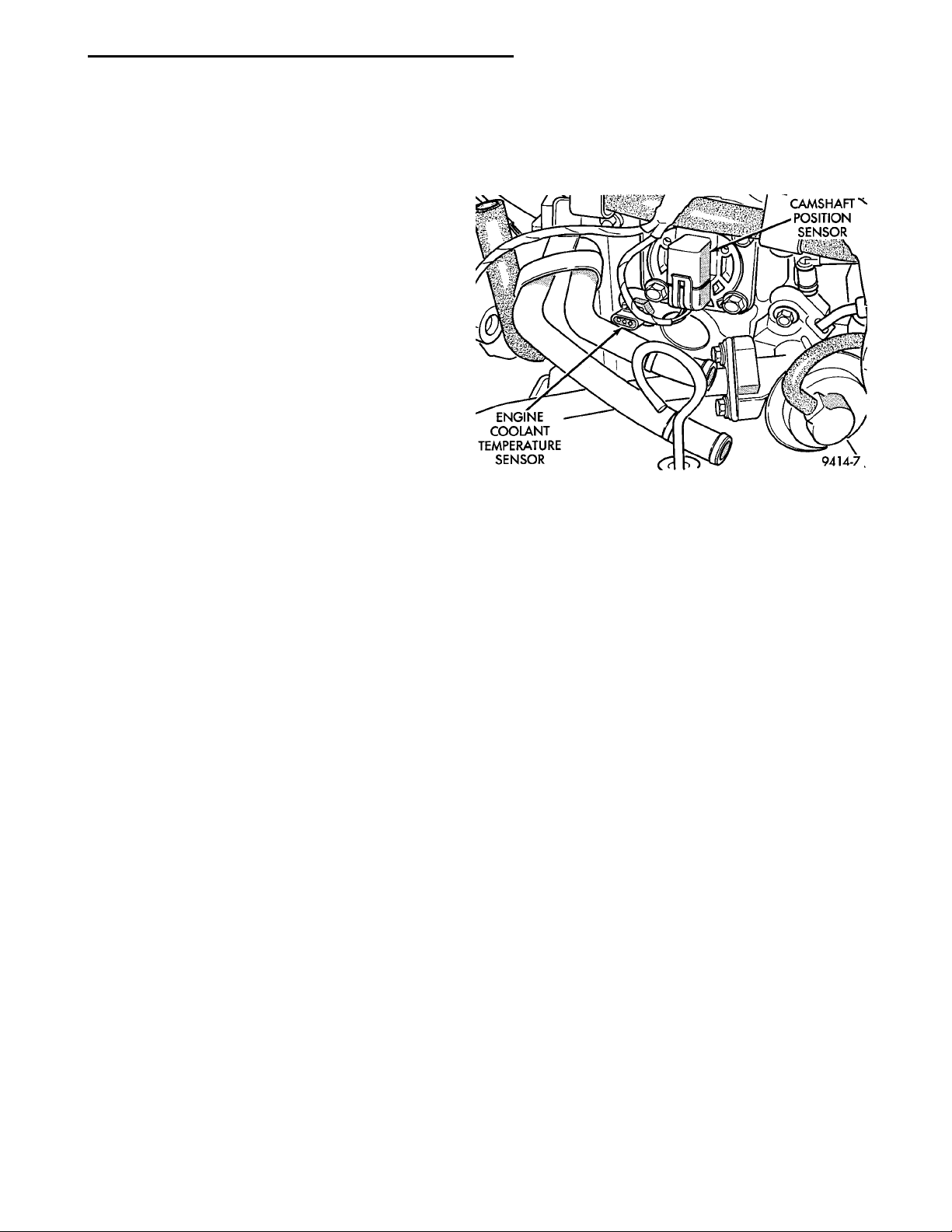
(1) Disconnect the coolant temperature sensor
(Fig. 15).
(2) Turn ignition switch ON. The temperature
gauge should be at its lowest position. Turn ignition
switch OFF.
(3) Ground temperature gauge sending unit con-
nector Pin 3. Refer to Group 8W, wiring Diagrams.
Turn ignition switch ON. The temperature gauge
should be at its highest position. After the seat belt
lamp goes out, the cluster should chime for about
eight seconds.
(a) If OK, check temperature sending unit connector for proper connection. If connections are OK,
replace the sending unit.
(b) If not OK, and the high temperature chime
sounds but the gauge shows cold, replace the gauge
assembly. If gauge is still not working, replace the
printed circuit board.
Fig. 15 Engine Coolant Temperature Sensor
SPEEDOMETER SYSTEM
The vehicle is equipped with a electronically driven
speedometer and odometer assemblies. A signal is
sent from a transmission-mounted vehicle speed sensor to the speedometer circuitry through the wiring
harness.
SEAT BELT REMINDER SYSTEM TEST
For testing of this system refer to Group 8U,
Chime Warning/Reminder Systems.
SENDING UNIT
When a problem occurs with a cluster gauge check
for a defective sending unit or wiring. Do this before
disassembling the cluster.
(1) Sending units and wiring can be checked by
grounding the connector leads at the sending unit in
the vehicle.
(2) With the ignition in the ON position, a
grounded input will cause the fuel or temperature
gauge to read at or above maximum.
SERVICE ENGINE SOON INDICATOR
Refer to Group 25, Emission Control Systems for
procedures.
VEHICLE SPEED SENSOR TEST
To test the vehicle speed sensor and related compo-
nents use a scan tool (DRB), and refer to the appropriate Powertrain Diagnostics Test Procedure
Manual.
Page 8
ILLUM AIR BAGHAZARD ILLUMT/SH/BS/B OIL
T/S ILLUM(OPT)ILLUMABS
ILLUM
BRAKEBATT
(OPT)
LOW FUEL
CHK ENG
8E - 8 INSTRUMENT PANEL AND SYSTEMS PL
REMOVAL AND INSTALLATION
ASH RECEIVER RETAINER AND LAMP
REMOVAL
(1) Remove the ash receiver receptacle.
(2) Remove the center bezel.
(3) Remove the two ash receiver retainer attaching
screws from the upper-rearward face and remove
retainer.
(4) For lamp replacement, remove the clamp and
lamp hood from the top of the retainer. Remove the
wiring clip at the forward edge of the retainer and
remove the lamp socket from the hood and replace
lamp.
INSTALLATION
For installation reverse the above procedures.
When installing the retainer ensure that the forward
tabs are inserted properly into the slots in the instrument panel.
CENTER BEZEL
REMOVAL
(1) Open the ash receiver receptacle.
(2) Grasp the bezel and pull rearward disengaging
the clips.
INSTALLATION
For installation, reverse the above procedures.
CIGAR LIGHTER RECEPTACLE
REMOVAL
(1) Remove the cigar lighter element.
(2) Reach underneath the instrument panel
through the bottom access hole and disconnect the
cigar lighter receptacle wiring connectors.
(3) Unscrew the cigar lighter receptacle shell from
the receptacle and remove from the base instrument
panel.
INSTALLATION
For installation, reverse the above procedures.
CLUSTER
CAUTION: Cluster MUST be stored in a face up
position or damage will occur to the gauge operation.
REMOVAL
(1) Disconnect the battery to ensure no DTCs are
generated.
(2) Remove the instrument panel top cover and
cluster bezel.
(3) Remove the four screws attaching cluster housing to the base panel.
(4) Pull the cluster rearward to disconnect from
base panel.
(5) Remove the cluster assembly.
INSTALLATION
For installation, reverse the above procedures.
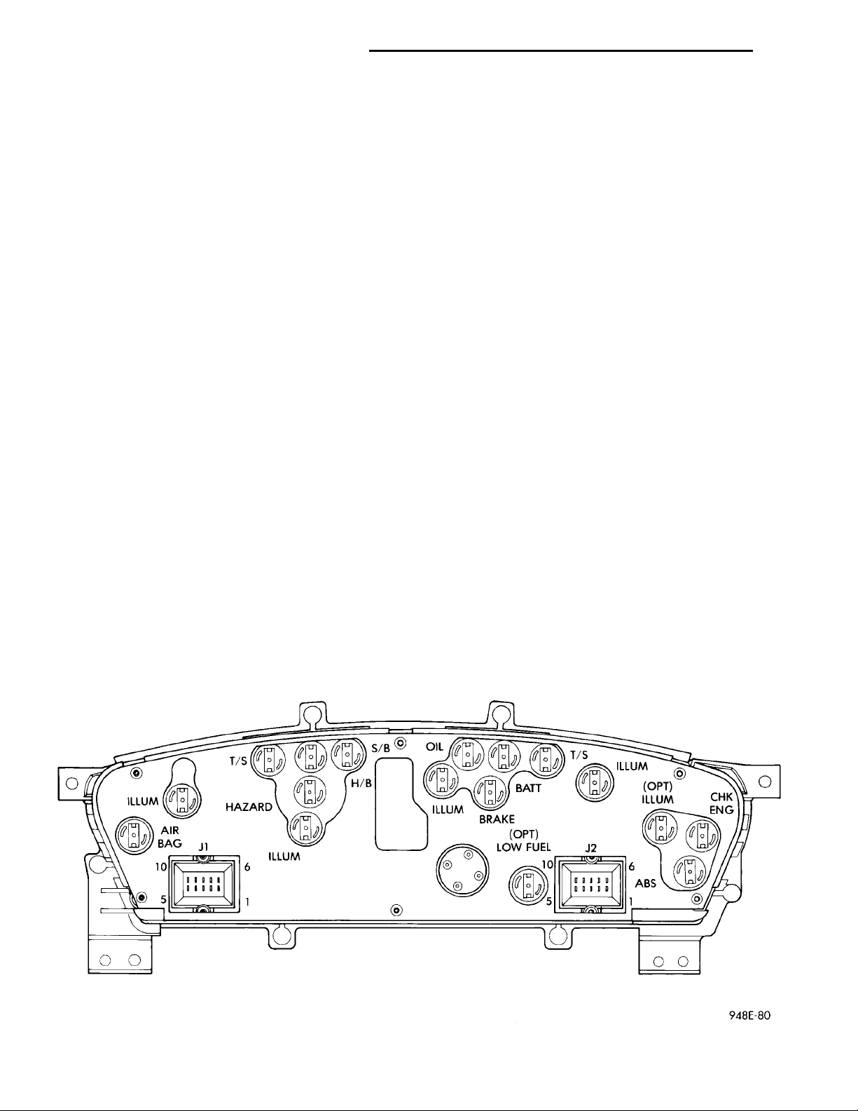
CLUSTER LAMP
The Instrument Cluster illumination Lamps location are shown in (Fig. 16). The cluster is viewed
from the rear. To replace lamp(s), the cluster must be
removed. Refer to Cluster Removal and Installation
procedure.
Fig. 16 Instrument Cluster Illumination Lamps
Page 9
ODOMETER CONNECTIONRETAINING SCREWS
PL INSTRUMENT PANEL AND SYSTEMS 8E - 9
REMOVAL AND INSTALLATION (Continued)
CLUSTER PRINTED CIRCUIT BOARD
REMOVAL
(1) Remove the cluster, refer to Cluster Removal.
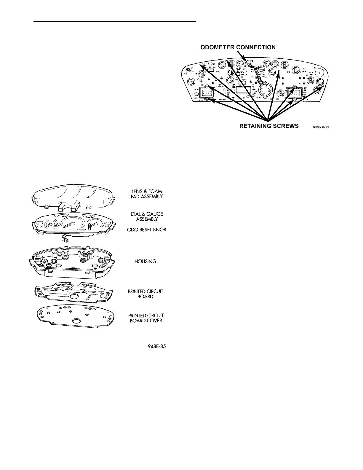
(2) Remove the attaching screws and rear cover
(Fig. 17). The bottom screws attaching lens to housing can be accessed without removing foam pad.
(3) Disconnect the odometer connector and remove
eight attaching screws that attach the printed circuit
board and housing (Fig. 18).
(4) Carefully remove printed circuit board from the
cluster.
INSTALLATION
For installation, reverse the above procedures.
Carefully place board on the cluster and ensure that
the odometer connector is placed through the board.
Gently press board on cluster with a slight rocking
motion to ensure pins on gauges line up.
Fig. 18 Printed Circuit Board
END CAP RHD
Removal
(1) Unlatch the glove box door and lower is to the
full open position.
(2) Remove the left trim panel as necessary to
remove the end cap attaching screws.
(3) Remove the end cap
Installation
For installation, reverse the above procedures.
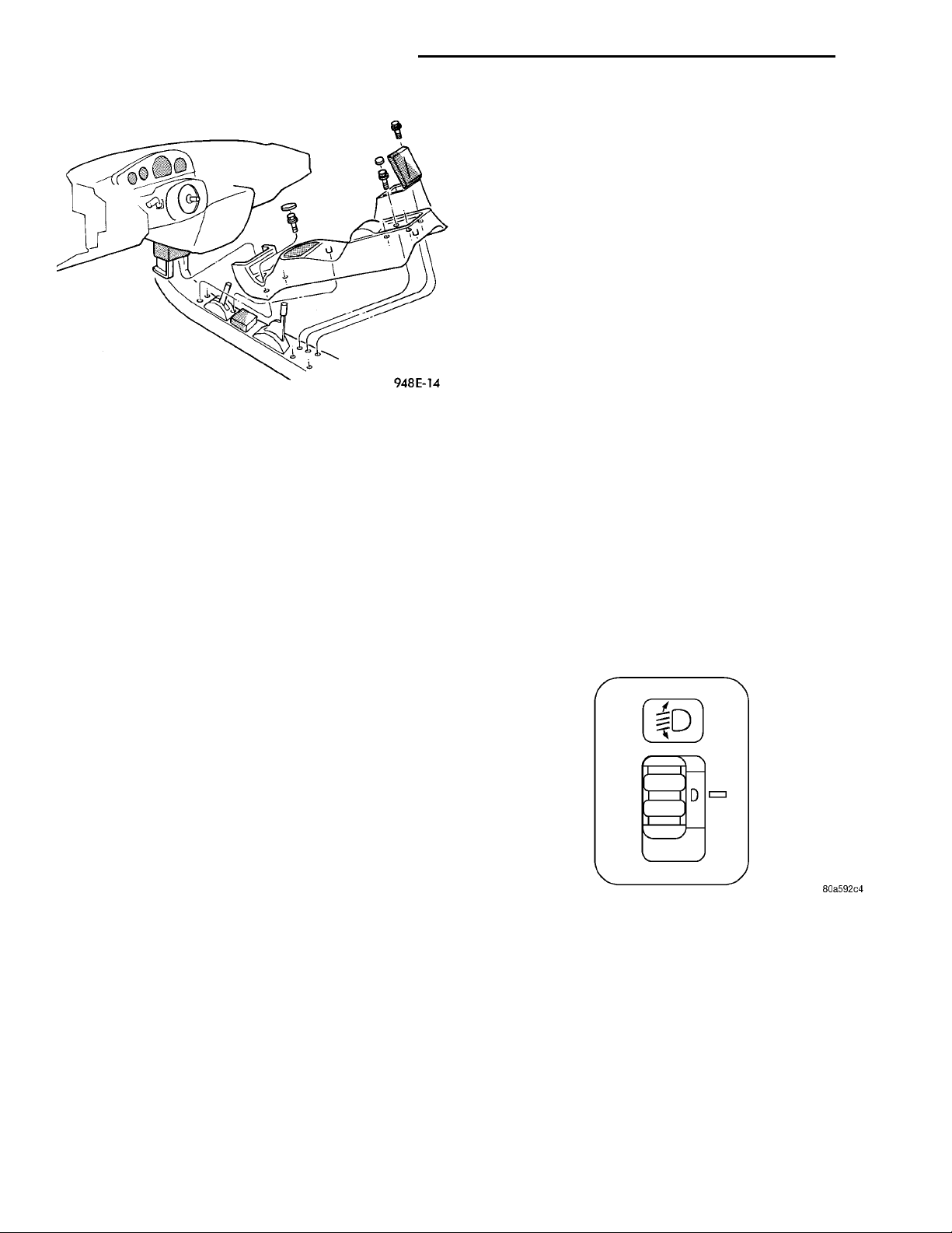
FLOOR CONSOLE
REMOVAL
(1) Remove the MTX shifter knob only.
(2) Remove the attaching screws from each side of
the cup holder.
(a) Non-armrest console. Remove the two screws
from the rear of the console (Fig. 19).
(b) Armrest console. Remove the four screws in
the console bin.
(3) Pull the parking brake lever up all the way.
(4) Lift the console at the rear and guide it out
from under the instrument panel.
Fig. 17 Cluster Assembly
DOME LENS/LAMP
REMOVAL
Pry either the forward or rearward edge of the lens
away from the retainer and replace the lamp.
INSTALLATION
For installation, snap lens into retainer.
INSTALLATION
For installation, reverse the above procedures.
FRONT FOG LAMP SWITCH EXPORT
REMOVAL
(1) Disconnect the wire connector in the center
stack, BUX left side and RHD right side.
(2) Remove the floor console and disconnect the
two clips attaching the wire harness from the underside of the floor console.
(3) Remove the switch bezel from the floor console.
INSTALLATION
For installation, reverse the above procedures.
Page 10
8E - 10 INSTRUMENT PANEL AND SYSTEMS PL
REMOVAL AND INSTALLATION (Continued)
GLOVE BOX SWITCH/LAMP
REMOVAL
(1) Disconnect battery negative cable and isolate it
or remove fuse 12 prior to removing the switch, or
wires may short to ground.
(2) Open the glove box and push the glove box
sides inward allowing the door bumpers to clear and
the box to tip forward.
(3) Reach inside the opening and squeeze the
lamp/switch retainers until they are disengage.
(4) Pull the switch/lamp rearward and remove it.
Replace the lamp. To replace the switch disconnect
wire and replace the switch.
INSTALLATION
Fig. 19 Floor Console with Transmission Range
For installation, reverse the above procedures.
Indicator
HEADLAMP LEVELING SWITCH EXPORT
GAUGE
REMOVAL
(1) Remove the cluster. Refer to Cluster Removal.
(2) Remove the attaching screws PC board cover
(Fig. 18). The bottom screws attaching lens to housing can be accessed without removing the foam pad.
(3) Disconnect the odometer connector.
(4) Remove the lens attaching screws and remove
the lens.
(5) Carefully pry out the dial and gauge assembly.
REMOVAL
(1) Remove the top cover and cluster bezel assem-
bly.
(2) Disengage the headlamp leveling switch bezel
from instrument panel (Fig. 20).
(3) Pull the switch and bezel rearward from the
opening and disconnect the wire connector.
INSTALLATION
For installation, reverse the above procedures.
INSTALLATION
For installation, reverse the above procedures.
(1) When handling or storing the cluster ensure
that overlays are not damaged. Set the cluster in the
face up position or the gauge operation will be damaged.
(2) The gauges are replaced as an dial and gauge
assembly.
GLOVE BOX DOOR/BIN
REMOVAL
(1) Disconnect battery negative cable and isolate it
or remove fuse 12 prior to removing the switch, or
the wires may short to ground.
(2) Remove the screws along the bottom of glove
box door.
(3) Open the glove box and push the glove box
sides inward allowing the door bumpers to clear and
box to tip forward.
(4) Pull the glove box door/bin rearward and
remove from vehicle.
installation
For installation, reverse the above procedures.
Fig. 20 Headlamp Leveling Switch
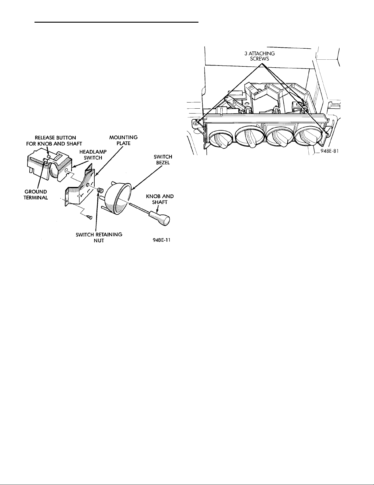
HEADLAMP SWITCH
REMOVAL
(1) Remove the steering column cover and liner.
(2) Remove the three screws securing headlamp
switch mounting plate to the instrument panel (Fig.
21).
(3) Pull the headlamp switch and mounting plate
rearward from the instrument panel opening.
(4) Disconnect both the nine way and the ground
wiring connectors from the switch.
Page 11
PL INSTRUMENT PANEL AND SYSTEMS 8E - 11
REMOVAL AND INSTALLATION (Continued)
(5) Remove the switch knob by depressing the
release button on the bottom on the switch and pulling out knob from switch.
(6) Snap headlamp switch bezel out of mounting
plate to gain access to the mounting plate retaining
nut.
(7) Remove the headlamp switch, mounting plate
retaining nut and separate switch from mounting
plate.
INSTALLATION
For installation, reverse the above procedures.
Fig. 22 HEATER A/C CONTROL
HEATER A/C CONTROL BLOWER SWITCH
The switch is not serviced, replace heater A/C control. Refer to the Heater A/C Control Removal and
Installation.
Fig. 21 Headlamp Switch
HEATER A/C CONTROL
REMOVAL
(1) Remove the top cover and cluster bezel.
(2) Reach in and disconnect the wiring connector(s)
for the rear window defogger and/or fog lamp
switch(s) as required.
(3) Remove the six attaching screws across the forward portion of the trim panel. Then lift the flange
forward to disengage the three locator pins.
(4) Pull panel rearward disengaging the clips
along the bottom.
(5) Open the ash receiver.
(6) Remove the center bezel.
(7) Remove three attaching screws at corners of
the control (Fig. 22).
(8) Pull the control rearward and disconnect the
wiring connector.
(9) Using a screwdriver, disengage the cable
attachment clips.
INSTALLATION
For installation, reverse the above procedures.
HEATER A/C CONTROL LAMP
REMOVAL
(1) Remove the Heater A/C Control. Refer to the
Heater A/C Control Removal.
(2) Remove the two center knobs by pulling the
knob rearward.
(3) Replace the lamp.
INSTALLATION
For installation, reverse the above procedures.
HEATER CONTROL BLOWER SWITCH
The switch is not serviced, replace the heater control. Refer to the A/C Heater Control Removal and
Installation.
IGNITION KEY LAMP
REMOVAL
(1) Remove the steering column cover. Refer to
Steering Column Cover Removal.
(2) Disconnect the lamp hood from the base panel.
(3) Remove the lamp socket from hood and replace
the lamp.
INSTALLATION
For installation, reverse the above procedures.
Page 12

8E - 12 INSTRUMENT PANEL AND SYSTEMS PL
REMOVAL AND INSTALLATION (Continued)
INSTRUMENT PANEL
REMOVAL
CAUTION: Disconnect battery negative cable, in
engine compartment, before servicing instrument
panel.
(1) Disconnect and isolate the battery negative
cable.
(2) Remove the floor console. Refer to Floor Con-
sole Removal.
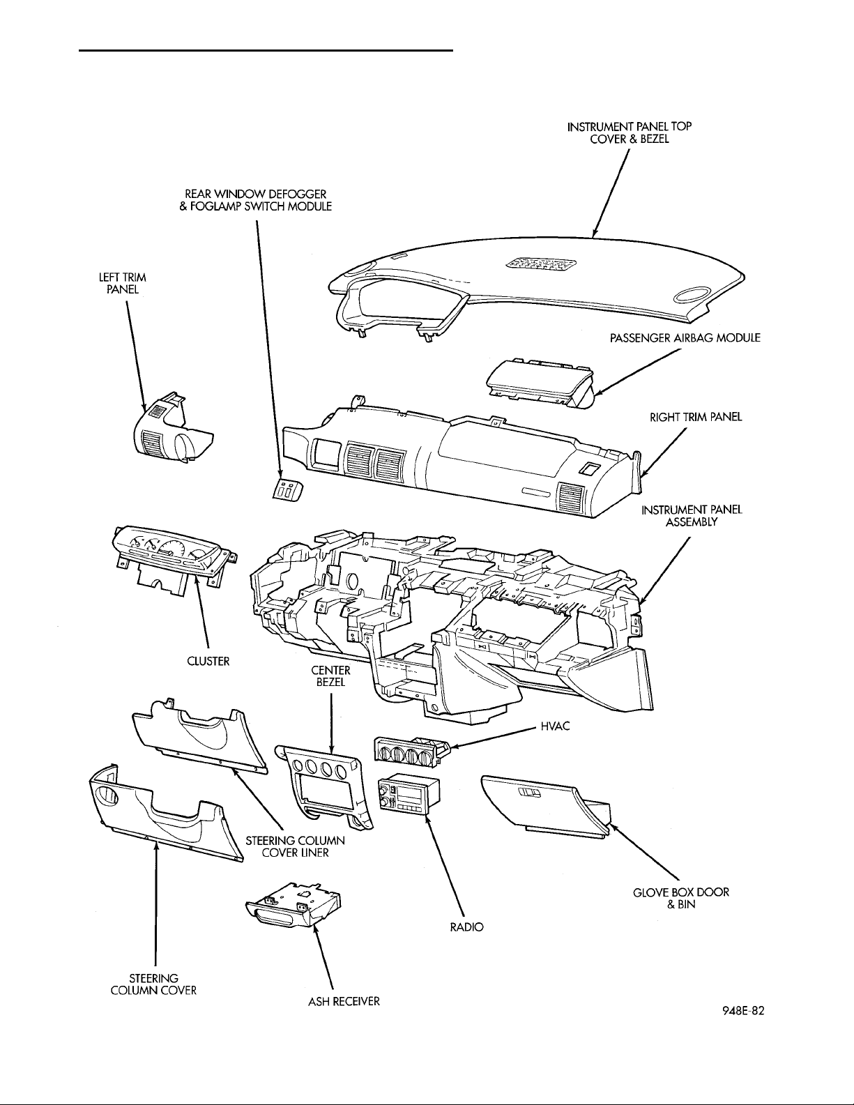
(3) Remove the right and left cowl side trim pan-
els (Fig. 23).
(4) Remove the steering column cover and liner.
(5) Remove the top cover and cluster bezel assem-
bly.
(6) Remove the right and left trim panel.
(7) Remove the defroster upper duct by lifting it
up.
(8) Remove the center outlet duct by pulling rear-
ward.
(9) Disconnect the Heater A/C Control, by removing the control cables clips with a screwdriver and
remove the wire connector.
(10) Disconnect the steering column at the bottom
slap together joint.
(11) Disconnect the ATX shifter interlock cable at
the shifter, if equipped.
(12) Disconnect the instrument panel wiring as
required.
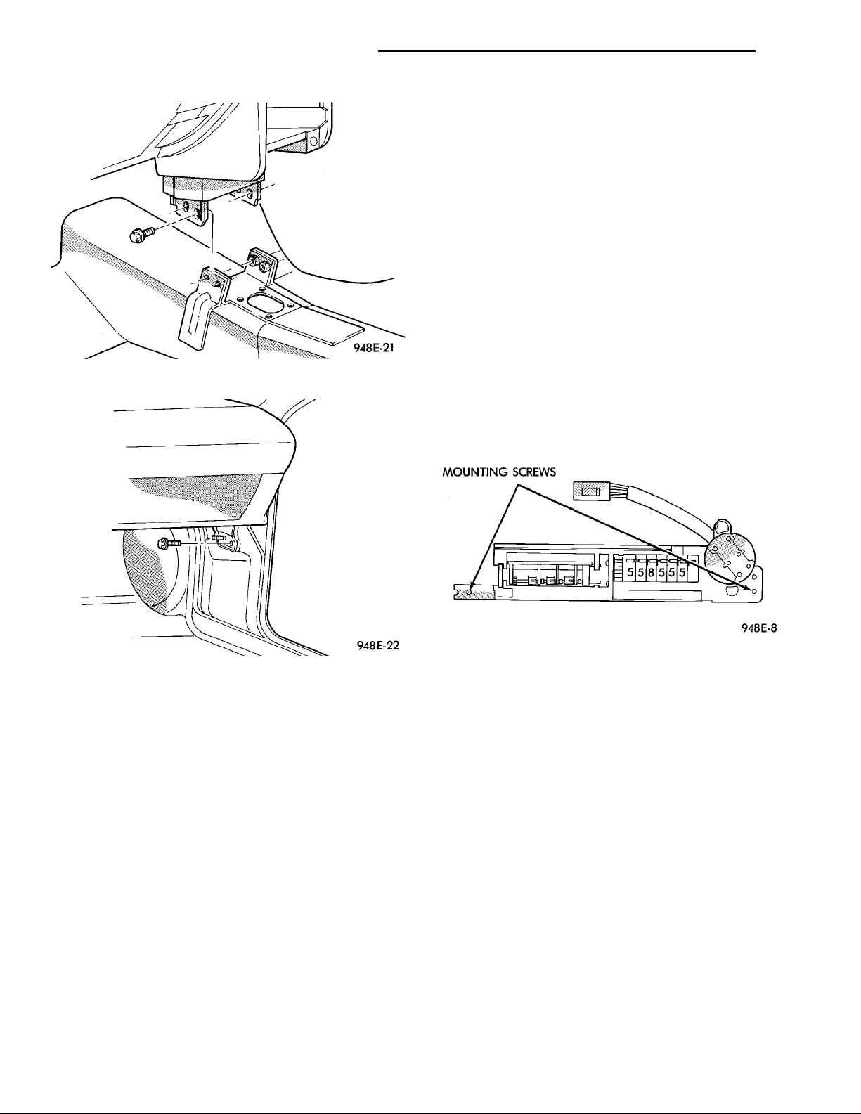
(13) Remove the four attaching screws at the cen-
ter floor pan bracket (Fig. 24).
(14) Remove the four attaching screws at steering
column.
(15) Remove the four cowl top nuts.
(16) Remove the attaching screws from the left
and right lower cowl side bracket (Fig. 25).
(17) Remove the two attaching screws from the left
upper cowl side and one from the right upper cowl
side.
(18) Pull the instrument panel rearward away
from the dash/plenum.
(19) Remove the instrument panel from vehicle.
INSTALLATION
For installation, reverse the above procedures.
CAUTION: Lock the steering wheel in the straight
ahead position. This will prevent clockspring damage when the steering wheel rotates freely.
Page 13
REAR WINDOW DEFOGGER& FOGLAMP SWITCH MOD-ULEINSTRUMENT PANEL TOPCOVER & BEZELPASSENGER AIRBAG MOD-ULE RIGHT TRIM PANELINSTRUMENT PANELASSEMBLY HVAC GLOVE BOX DOOR & BINRADIO ASH RECEIVERSTEERING COLUMN COVERSTEERING COLUMN COVERLINERCENTER BEZELCLUSTERLEFT TRIM PANEL
PL INSTRUMENT PANEL AND SYSTEMS 8E - 13
REMOVAL AND INSTALLATION (Continued)
Fig. 23 Instrument Panel Assembly
Page 14
8E - 14 INSTRUMENT PANEL AND SYSTEMS PL
REMOVAL AND INSTALLATION (Continued)
(4) Remove the screws attaching PC board cover to
cluster.
(5) Disconnect the odometer connector from the
printed circuit board.
(6) Remove the screws attaching lens, dial and
gauge assembly to the housing. The bottom screws
attaching lens to the housing can be accessed without
removing the foam pad.
(7) Remove the lens, dial and gauge assembly from
housing.
(8) Remove the two screws holding the odometer to
dial and gauge assembly. When setting the dial/gauge
and/or cluster assembly down, it must be face up or
the gauge operation will be damaged.
INSTALLATION
Fig. 24 Center Floor Pan Bracket
For installation, reverse the above procedures.
Carefully place the dial and gauge assembly on the
cluster and ensure that the odometer connector is
placed through the board. Install with a slight rocking motion to ensure the pins on gauges line up.
Fig. 25 Side Bracket
LEFT TRIM PANEL
REMOVAL
(1) Remove the top cover and cluster bezel (Fig.
23).
(2) Remove the steering column cover.
(3) Remove the two attaching screws along the
bottom and the one at the top of the trim panel and
pull rearward to remove.
INSTALLATION
For installation, reverse the above procedures.
ODOMETER
REMOVAL
(1) Remove the instrument panel top cover and
cluster bezel.
(2) Remove the four screws attaching cluster to
instrument panel (Fig. 26).
(3) Remove the cluster.
Fig. 26 Odometer
RADIO
For Radio removal procedures, Refer to Group 8F,
Audio Systems.
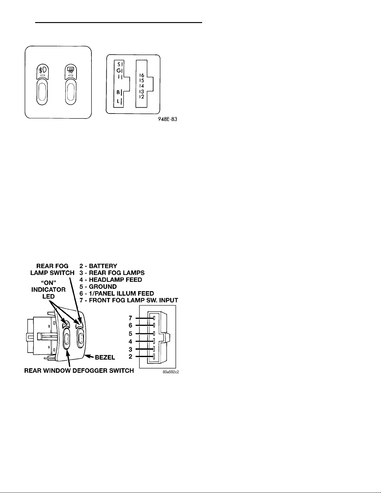
REAR WINDOW DEFOGGER AND/OR FOG LAMP SWITCH
REMOVAL
(1) Remove the top cover and cluster bezel assembly. Refer to the Top Cover and Cluster Bezel
Removal above.
(2) Reach in and disengage the left bezel latch and
remove assembly (Fig. 27).
(3) Pull the bezel and switch(s) rearward from the
opening and disconnect the wire connector(s).
(4) Remove the switch from the bezel.
INSTALLATION
For installation, reverse the above procedures.
Page 15
REAR FOG LAMP SWITCH2 — BATTERY3 — REAR FOG LAMPS4 — HEADLAMP FEED5 — GROUND6 — 1/PANEL ILLUM FEED7 — FRONT FOG LAMP SW.INPUTREAR WINDOW DEFOGGERSWITCHBEZEL88ON” INDICATOR LED
PL INSTRUMENT PANEL AND SYSTEMS 8E - 15
REMOVAL AND INSTALLATION (Continued)
(3) Remove the six attaching screws across the forward portion of the trim panel. Then lift flange forward to disengage the three locator pins.
(4) Pull the panel rearward until the clips along
the bottom disengage.
INSTALLATION
For installation, reverse the above procedures.
SHIFTER KNOB
Fig. 27 Rear Window Defogger and Fog Lamp
Switch
REAR WINDOW DEFOGGER AND/OR REAR FOG LAMP SWITCH EXPORT
REMOVAL
(1) Remove the top cover and cluster bezel assembly. Refer to Top Cover and Cluster Bezel Removal
above.
(2) Reach in and disengage the left bezel latch and
remove the assembly (Fig. 28).
(3) Pull the bezel and switch(s) rearward from the
opening and disconnect the wire connector(s).
(4) Remove the switch from the bezel.
INSTALLATION
For installation, reverse the above procedures.
ATX SHIFTER
REMOVAL
(1) Loosen the set screw at the left side under the
button area.
(2) Pull up until the knob slides off the shifter
shaft.
INSTALLATION
For installation, reverse the above procedures.
MTX SHIFTER
REMOVAL
(1) Pull the top part of the boot down until the two
tabs at the bottom of the knob are exposed.
(2) Release the locking tabs from the pins on the
shifter shaft.
(3) Pull up until the knob slides off the shifter
shaft.
INSTALLATION
For installation, reverse the above procedures.
STEERING COLUMN COVER
Fig. 28 Rear Window Defogger and Rear Fog Lamp
Switch
RIGHT TRIM PANEL
REMOVAL
(1) Remove the top cover and cluster bezel (Fig.
23).
(2) Reach in and disconnect the wiring connector(s)
for the rear window defogger and/or fog lamp
switch(s) as required.
REMOVAL
(1) Remove the three attachment screws along the
bottom of the cover and screw on the left outward
face of cover (Fig. 29).
(2) Grasp the cover and pull rearward until the
clips disengage.
INSTALLATION
For installation, reverse the above procedures.
STEERING COLUMN COVER LINER
REMOVAL
(1) Remove the steering column cover (Fig. 23).
(2) Remove the two attachment screws at the
upper area of the liner and the lower left corner.
INSTALLATION
For installation, reverse the above procedures.
Page 16
LEFT TRIM PANEL
INSTRUMENT PANEL TOP COVER AND
UPPER COVER SHROUDSTEERING COLUMNLOWER COVER SHROUDACCESS HOLE FOR KEYCYLINDER REMOVAL
RIGHT TRIM PANELSTEERING COLUMN COVERSTEERING COLUMNCOVER LINER
CLUSTER BEZEL
8E - 16 INSTRUMENT PANEL AND SYSTEMS PL
REMOVAL AND INSTALLATION (Continued)
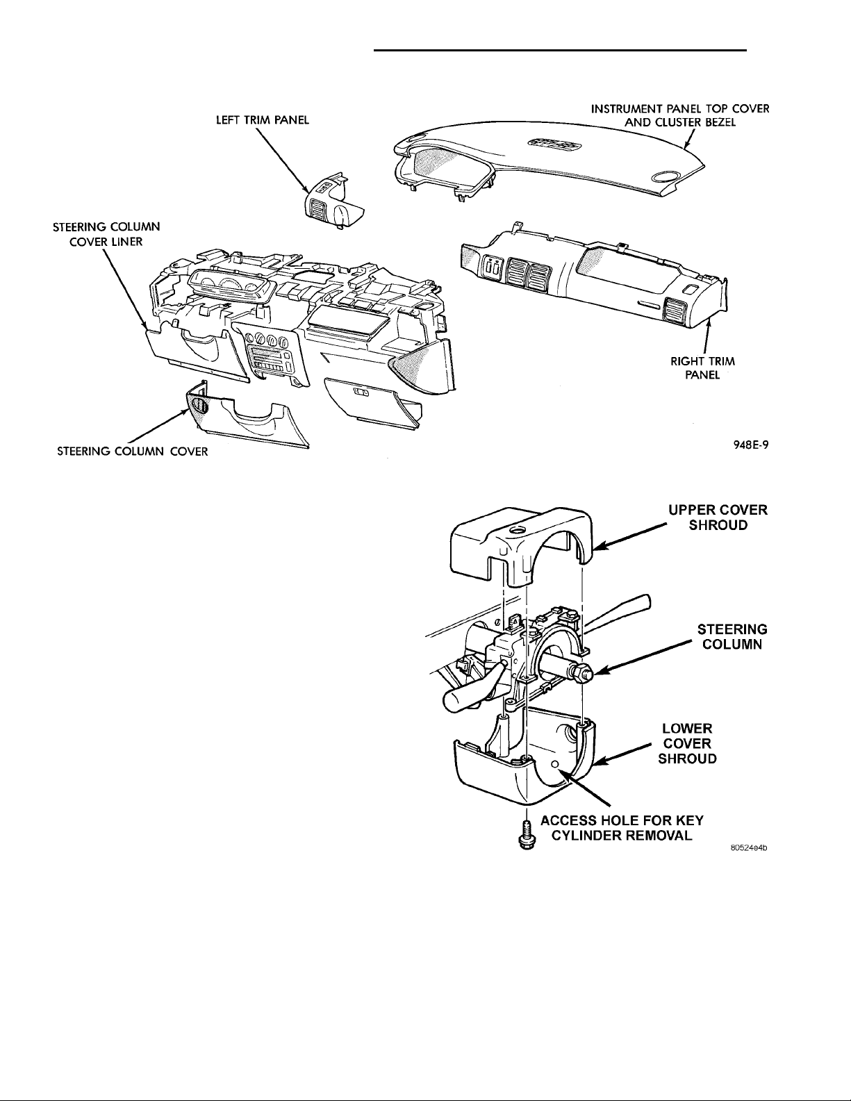
Fig. 29 Instrument Panel and Top Cover
STEERING COLUMN SHROUDS
(1) Remove the steering column cover and steering
column cover liner.
(2) Lift up the top cover and cluster bezel until the
clips disengage and separate to provide clearance
(Fig. 30).
(3) Rotate the ignition key cylinder to run/on position. Insert a screw driver into the access hole at the
bottom of lower shroud to release the ignition key
cylinder.
(4) Pull out the ignition key cylinder.
(5) Remove the three lower to upper shroud
attaching screws through the bottom of the lower
shroud.
(6) Separate the upper and lower shrouds.
INSTALLATION
For installation, reverse the above procedures.
TOP COVER AND CLUSTER BEZEL REMOVAL
REMOVAL
(1) Use care not to scratch the panel. Lift up on
the bottom outer areas of the cluster bezel and along
the rearward edge of the top cover to disengage the
clips (Fig. 29).
(2) Pull the top cover and cluster bezel rearward
until the forward pins disengage from the instrument
panel.
Fig. 30 Upper/Lower Shroud
INSTALLATION
For installation, reverse the above procedures.
Position spring clips to instrument panel and push
firmly until seated.
TRANSMISSION RANGE INDICATOR LAMP
REMOVAL
(1) Raise the floor console (Fig. 19).
Page 17
SENSORCONNECTOR TRANSAXLE EXTENSIONVEHICLE SPEED SENSORSENSOR RETAINING BOLT
SENSORRETAININGBOLTTRANSAXLE EXTENSION SPEEDOMETER PINIONVEHICLE SPEED SENSOR
PL INSTRUMENT PANEL AND SYSTEMS 8E - 17
REMOVAL AND INSTALLATION (Continued)
(2) Remove the attaching screw from each of the
two forward cup holders of the floor console. Remove
the screws at the rear of the console or inside of the
armrest console bin.
(3) Pull the parking brake lever all the way up.
(4) Lift the floor console at the rear high enough to
gain access to the lamp and socket.
(5) Remove the indicator lamp socket from bezel to
replace the lamp.
INSTALLATION
For installation, reverse the above procedures.
TRUNK LAMP/LENS
REMOVAL
The trunk lamp snaps into the rear shelf panel
reinforcement under/below the package shelf.
(1) Remove the socket assembly by reaching up
above the sheet metal. Push the snap inward and
downward and remove the assembly.
(2) Remove the lamp from socket and pull the
socket from the lens. Replace as necessary.
INSTALLATION
For installation, reverse the above procedures.
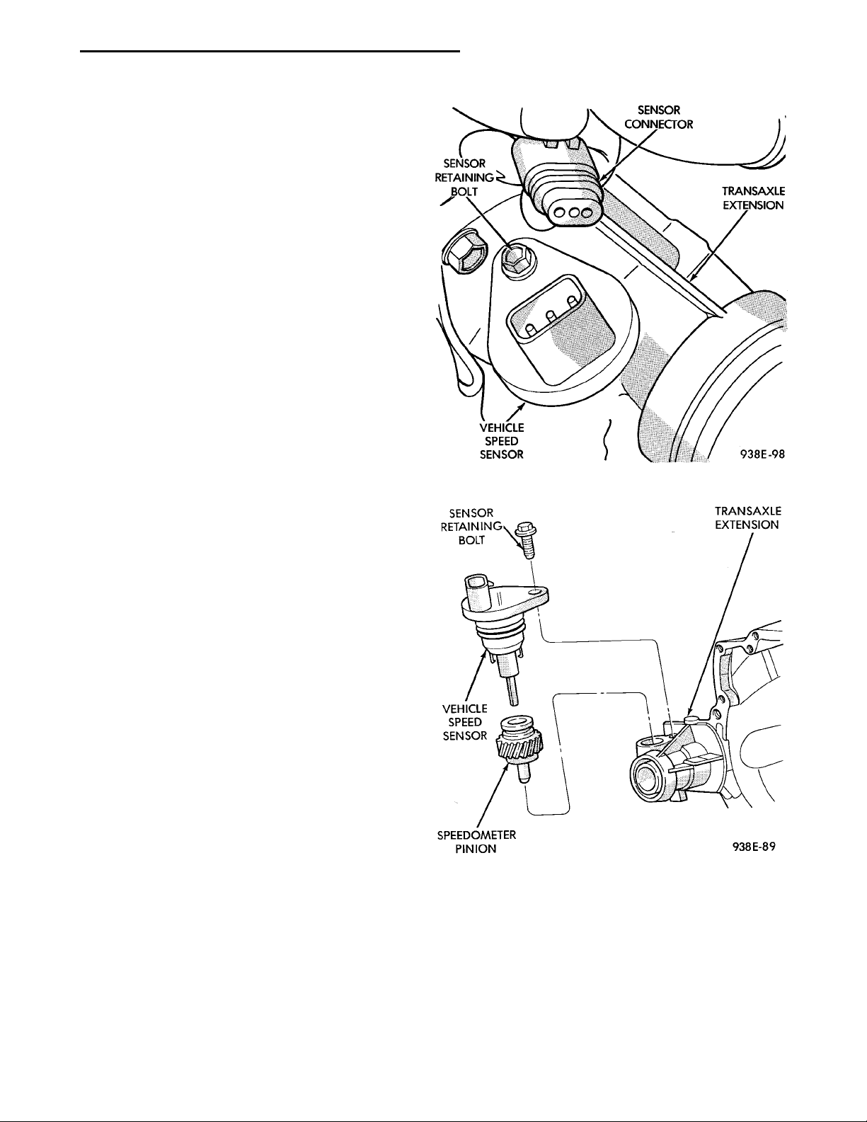
Fig. 31 Vehicle Speed Sensor and Connector
VEHICLE SPEED SENSOR
REMOVAL
(1) Remove the harness connector from the sensor
and make sure the weather seal is on the harness
connector.
(2) Remove the sensor retaining bolt.
(3) Pull the sensor and pinion gear assembly out of
transaxle. If necessary, carefully pry it loose with a
flat blade tool (Fig. 31) and (Fig. 32).
INSTALLATION
For installation, reverse the above procedures. Seat
the sensor assembly by hand to ensure proper gear
engagement. Tighten retaining bolt to 7 N·m (60 in.
lbs.) torque.
Fig. 32 Vehicle Speed Sensor and Speedometer
Pinion
Page 18

8E - 18 INSTRUMENT PANEL AND SYSTEMS PL
REMOVAL AND INSTALLATION (Continued)
 Loading...