

Page 1

PL IGNITION SYSTEM 8D - 1
IGNITION SYSTEM
CONTENTS
page page
GENERAL INFORMATION
INTRODUCTION ........................ 1
DESCRIPTION AND OPERATION
AUTOMATIC SHUTDOWN RELAY ........... 3
CAMSHAFT POSITION SENSOR ............ 4
COMBINATION ENGINE COOLANT
TEMPERATURE SENSOR ................ 5
CRANKSHAFT POSITION SENSOR .......... 3
ELECTRONIC IGNITION COILS ............. 3
IGNITION INTERLOCK .................... 7
IGNITION SWITCH ....................... 7
IGNITION SYSTEM ...................... 1
INTAKE AIR TEMPERATURE SENSOR ....... 6
KNOCK SENSOR ........................ 6
LOCK KEY CYLINDER .................... 7
MANIFOLD ABSOLUTE PRESSURE SENSOR
(MAP) ............................... 6
POWERTRAIN CONTROL MODULE .......... 2
SPARK PLUG CABLES ................... 2
SPARK PLUGS ......................... 2
THROTTLE POSITION SENSOR (TPS) ....... 7
DIAGNOSIS AND TESTING
CAMSHAFT POSITION SENSOR AND
CRANKSHAFT POSITION SENSOR ........ 9
CHECK COIL TEST ...................... 8
ENGINE COOLANT TEMPERATURE SENSOR . . 9
FAILURE TO START TEST—2.0/2.4L ......... 8
IGNITION TIMING PROCEDURE ............ 9
INTAKE AIR TEMPERATURE SENSOR ....... 9
MANIFOLD ABSOLUTE PRESSURE (MAP)
SENSOR TEST ........................ 9
SPARK PLUG CONDITION ................ 10
TESTING FOR SPARK AT COIL—2.0/2.4L ..... 7
THROTTLE POSITION SENSOR ............ 9
REMOVAL AND INSTALLATION
AUTOMATIC SHUTDOWN RELAY .......... 13
CAMSHAFT POSITION SENSOR—DOHC .... 14
CAMSHAFT POSITION SENSOR—SOHC .... 13
COMBINATION ENGINE COOLANT
TEMPERATURE SENSOR—DOHC ........ 15
COMBINATION ENGINE COOLANT
TEMPERATURE SENSOR—SOHC ........ 15
CRANKSHAFT POSITION SENSOR ......... 15
IGNITION COIL ........................ 13
IGNITION INTERLOCK ................... 17
IGNITION SWITCH ...................... 16
LOCK CYLINDER HOUSING .............. 17
LOCK KEY CYLINDER ................... 17
MAP/IAT SENSOR—DOHC ................ 16
MAP/IAT SENSOR—SOHC ................ 16
POWERTRAIN CONTROL MODULE (PCM) . . . 12
SPARK PLUG CABLE SERVICE ............ 12
SPARK PLUG SERVICE .................. 12
SPARK PLUG TUBES ................... 13
THROTTLE POSITION SENSOR ........... 16
SPECIFICATIONS
FIRING ORDER—2.0L ................... 18
IGNITION COIL ........................ 18
SPARK PLUG CABLE RESISTANCE—DOHC . . 18
SPARK PLUG CABLE RESISTANCE—SOHC . . 18
SPARK PLUG .......................... 18
TORQUE SPECIFICATION ................ 18
VECI LABEL ........................... 18
GENERAL INFORMATION
INTRODUCTION
This section describes the electronic ignition sys-
tem for the 2.0L engines used in Neon vehicles.
The On-Board Diagnostics Section in Group 25
describes diagnostic trouble codes.
Group 0, Lubrication and Maintenance, contains
general maintenance information for ignition related
items. The Owner’s Manual also contains maintenance information.
DESCRIPTION AND OPERATION
IGNITION SYSTEM
Ignition system operation and diagnostics, are
identical for 2.0L Single Overhead Cam (SOHC) and
2.0L Duel Overhead Cam (DOHC) engines.
The major difference between the two engines is
component location which affects the ignition system
service procedures. There are various sensors that
are in different locations due to a different cylinder
head and intake manifold.
Page 2
8D - 2 IGNITION SYSTEM PL
POWER DISTRI-BUTION CEN-TER PCM40–WAY CONNECTOR BATTERY
GAUGESPARK PLUG
DESCRIPTION AND OPERATION (Continued)
The 2.0L engines use a fixed ignition timing system. The distributorless electronic ignition system is
referred to as the Direct Ignition System (DIS).
Basic ignition timing is not adjustable. The
Powertrain Control Module (PCM) determines spark
advance. The system’s three main components are
the coil pack, crankshaft position sensor, and camshaft position sensor.
POWERTRAIN CONTROL MODULE
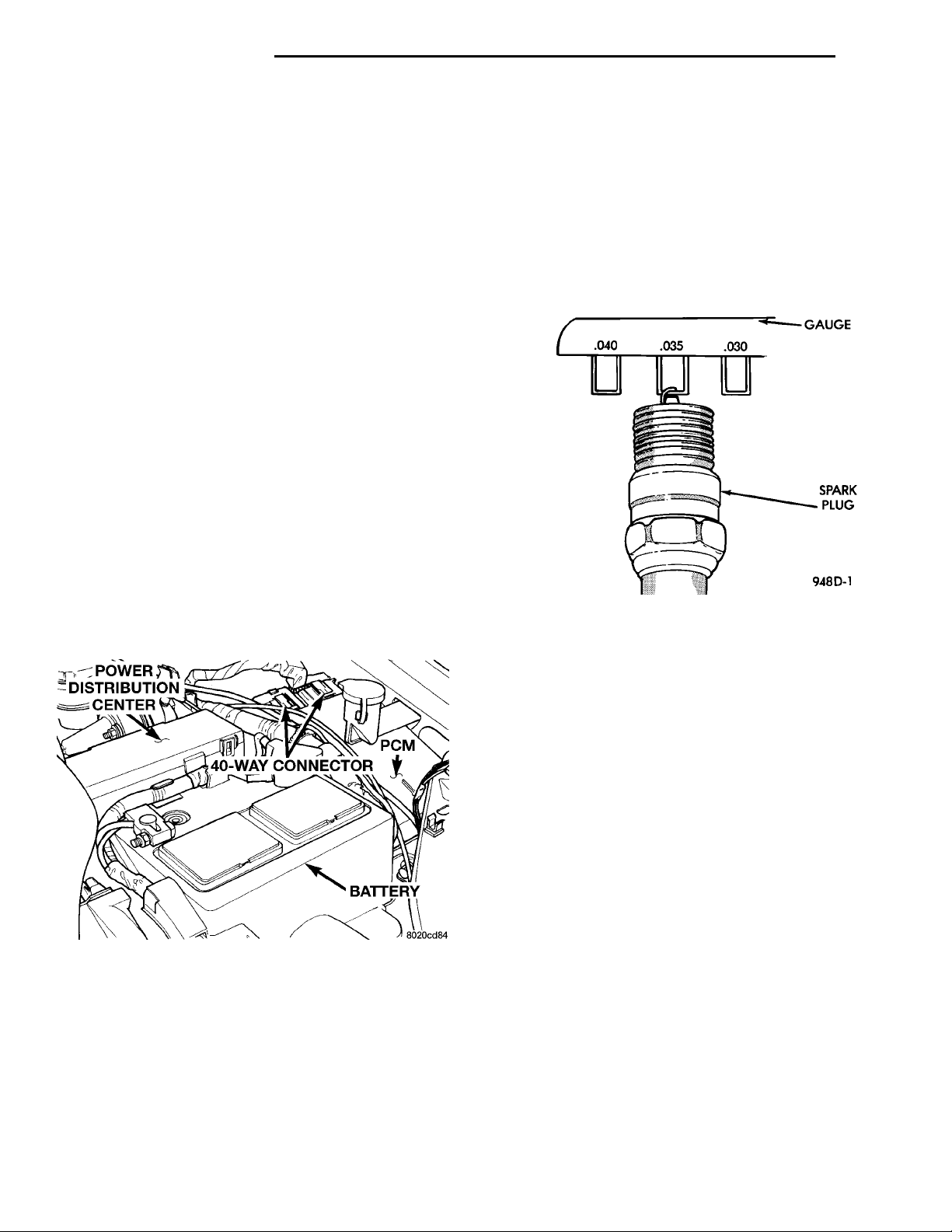
The Powertrain Control Module (PCM) regulates
the ignition system (Fig. 1). The PCM supplies battery voltage to the ignition coil through the Auto
Shutdown (ASD) Relay. The PCM also controls the
ground circuit for the ignition coil. By switching the
ground path for the coil on and off, the PCM adjusts
ignition timing to meet changing engine operating
conditions.
During the crank-start period the PCM maintains
spark advance at 9° BTDC. During engine operation
the following inputs determine the amount of spark
advance provided by the PCM.
• Intake air temperature
• Coolant temperature
• Engine RPM
• Intake manifold vacuum
• Knock sensor
The PCM also regulates the fuel injection system.
Refer to the Fuel Injection sections of Group 14.
that a problem exists in the corresponding cylinder.
Replace spark plugs at the intervals recommended in
Group 0.
Spark plugs that have low mileage may be cleaned
and reused if not otherwise defective. Refer to the
Spark Plug Condition section of this group. After
cleaning, file the center electrode flat with a small
point file or jewelers file. Adjust the gap between the
electrodes (Fig. 2) to the dimensions specified in the
chart at the end of this section.
Fig. 2 Setting Spark Plug Electrode Gap
Always tighten spark plugs to the specified torque.
Over tightening can cause distortion and change the
spark plug gap. Tighten spark plugs to 28 N·m (20 ft.
lbs.) torque.
Fig. 1 Powertrain Control Module
SPARK PLUGS
The 2.0L engines uses resistor spark plugs. For
spark plug identification and specifications, Refer to
the Specifications section at the end of this group.
Remove the spark plugs and examine them for
burned electrodes and fouled, cracked or broken porcelain insulators. Keep plugs arranged in the order
in which they were removed from the engine. An isolated plug displaying an abnormal condition indicates
SPARK PLUG CABLES
Spark plug cables are sometimes referred to as secondary ignition wires. The wires transfer electrical
current from the coil pack to individual spark plugs
at each cylinder. The resistor type, nonmetallic spark
plug cables provide suppression of radio frequency
emissions from the ignition system.
Check the spark plug cable connections for good
contact at the coil and spark plugs. Terminals should
be fully seated. The nipples and spark plug covers
should be in good condition. Nipples should fit tightly
on the coil. Spark plug boot should completely cover
the spark plug hole in the cylinder head cover. Install
the boot until the terminal snaps over the spark
plug. A snap must be felt to ensure the spark plug
cable terminal engaged the spark plug.
Loose cable connections will corrode, increase resistance and permit water to enter the coil towers.
These conditions can cause ignition malfunction.
Plastic clips in various locations protect the cables
from damage. When the cables are replaced the clips
must be used to prevent damage to the cables. The
Page 3
IGNITIONCOILSSPARK PLUGINSULATOR
PL IGNITION SYSTEM 8D - 3
DESCRIPTION AND OPERATION (Continued)
IGNITIONCOILSSPARK PLUG CABLESPARK PLUGINSULATOR
SPEED CONTROL SERVO
POWER DISTRIBUTION CEN-
PCMBATTERY
TER
#1 cable must be routed under the PCV hose and
clipped to the #2 cable.
ELECTRONIC IGNITION COILS
WARNING: THE DIRECT IGNITION SYSTEM GENERATES APPROXIMATELY 40,000 VOLTS. PERSONAL INJURY COULD RESULT FROM CONTACT
WITH THIS SYSTEM.
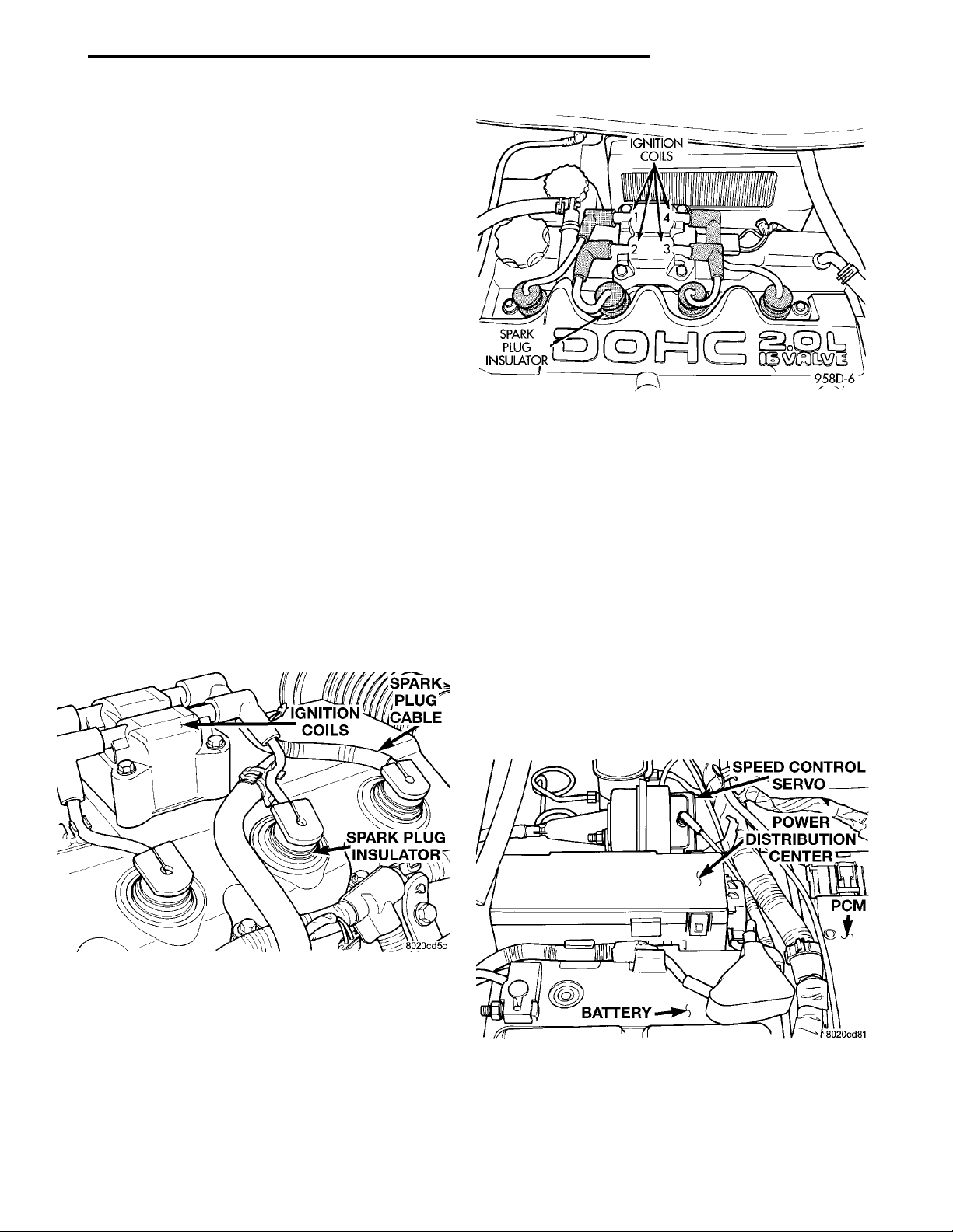
The coil pack consists of 2 coils molded together.
The coil pack is mounted on the valve cover (Fig. 3)
or (Fig. 4). High tension leads route to each cylinder
from the coil. The coil fires two spark plugs every
power stroke. One plug is the cylinder under compression, the other cylinder fires on the exhaust
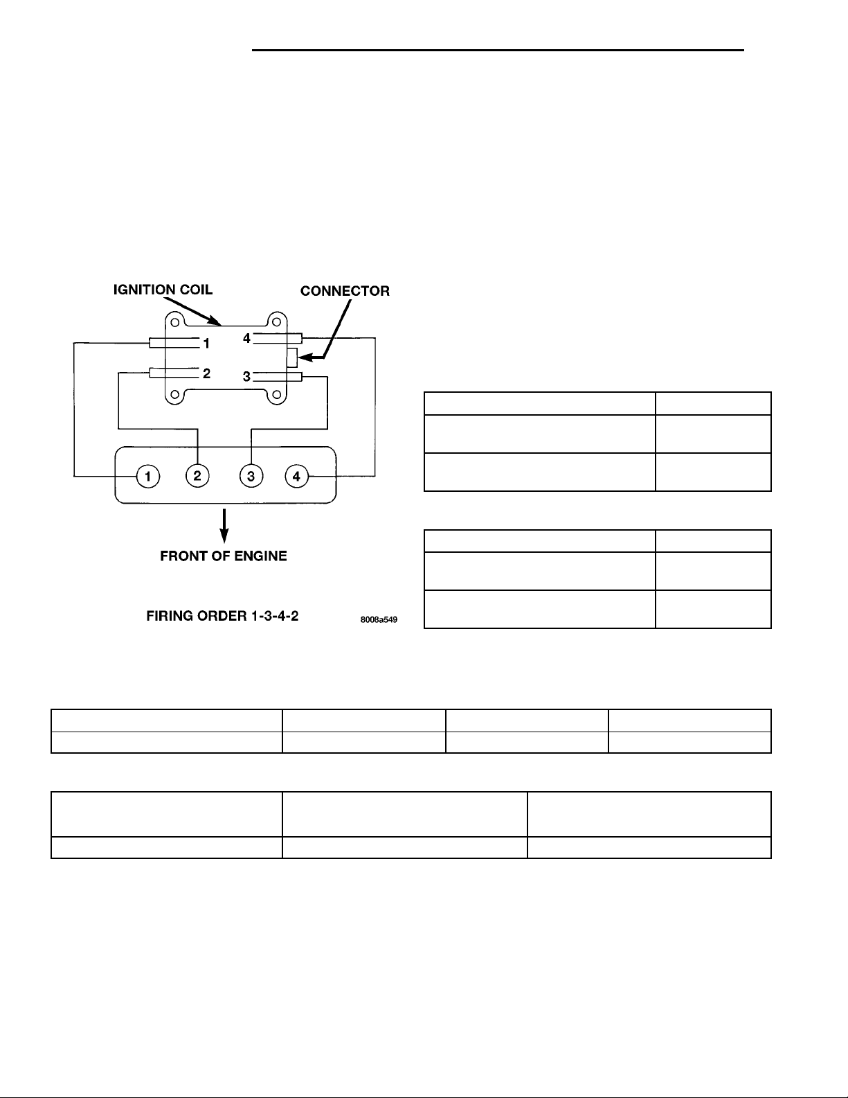
stroke. Coil number one fires cylinders 1 and 4. Coil
number two fires cylinders 2 and 3. The PCM determines which of the coils to charge and fire at the correct time.
The Auto Shutdown (ASD) relay provides battery
voltage to the ignition coil. The PCM provides a
ground contact (circuit) for energizing the coil. When
the PCM breaks the contact, the energy in the coil
primary transfers to the secondary causing the
spark. The PCM will de-energize the ASD relay if it
does not receive the crankshaft position sensor and
camshaft position sensor inputs. Refer to Auto Shutdown (ASD) Relay—PCM Output, in this section for
relay operation.
the fuel pump relay and pump. The fuse is located in
the PDC. Refer to Group 8W, Wiring Diagrams for
circuit information.
The PCM controls the ASD relay by switching the
ground path for the solenoid side of the relay on and
off. The PCM turns the ground path off when the
ignition switch is in the Off position. When the ignition switch is in On or Start, the PCM monitors the
crankshaft and camshaft position sensor signals to
determine engine speed and ignition timing (coil
dwell). If the PCM does not receive crankshaft and
camshaft position sensor signals when the ignition
switch is in the Run position, it will de-energize the
ASD relay.
The ASD relay is located in the PDC (Fig. 5). The
inside top of the PDC cover has label showing relay
and fuse identification.
Fig. 4 Ignition Coil Pack—DOHC
Fig. 3 Ignition Coil Pack—SOHC
AUTOMATIC SHUTDOWN RELAY
The Automatic Shutdown (ASD) relay supplies battery voltage to the fuel injectors, electronic ignition
coil and the heating elements in the oxygen sensors.
A buss bar in the Power Distribution Center (PDC)
supplies voltage to the solenoid side and contact side
of the relay. The ASD relay power circuit contains a
20 amp fuse between the buss bar in the PDC and
the relay. The fuse also protects the power circuit for
Fig. 5 Power Distribution Center (PDC)
CRANKSHAFT POSITION SENSOR
The PCM determines what cylinder to fire from the
crankshaft position sensor input and the camshaft
position sensor input. The second crankshaft counter-
Page 4
CRANKSHAFT POSITIONSENSOROIL FILTERGENERATOR
8D - 4 IGNITION SYSTEM PL
DESCRIPTION AND OPERATION (Continued)
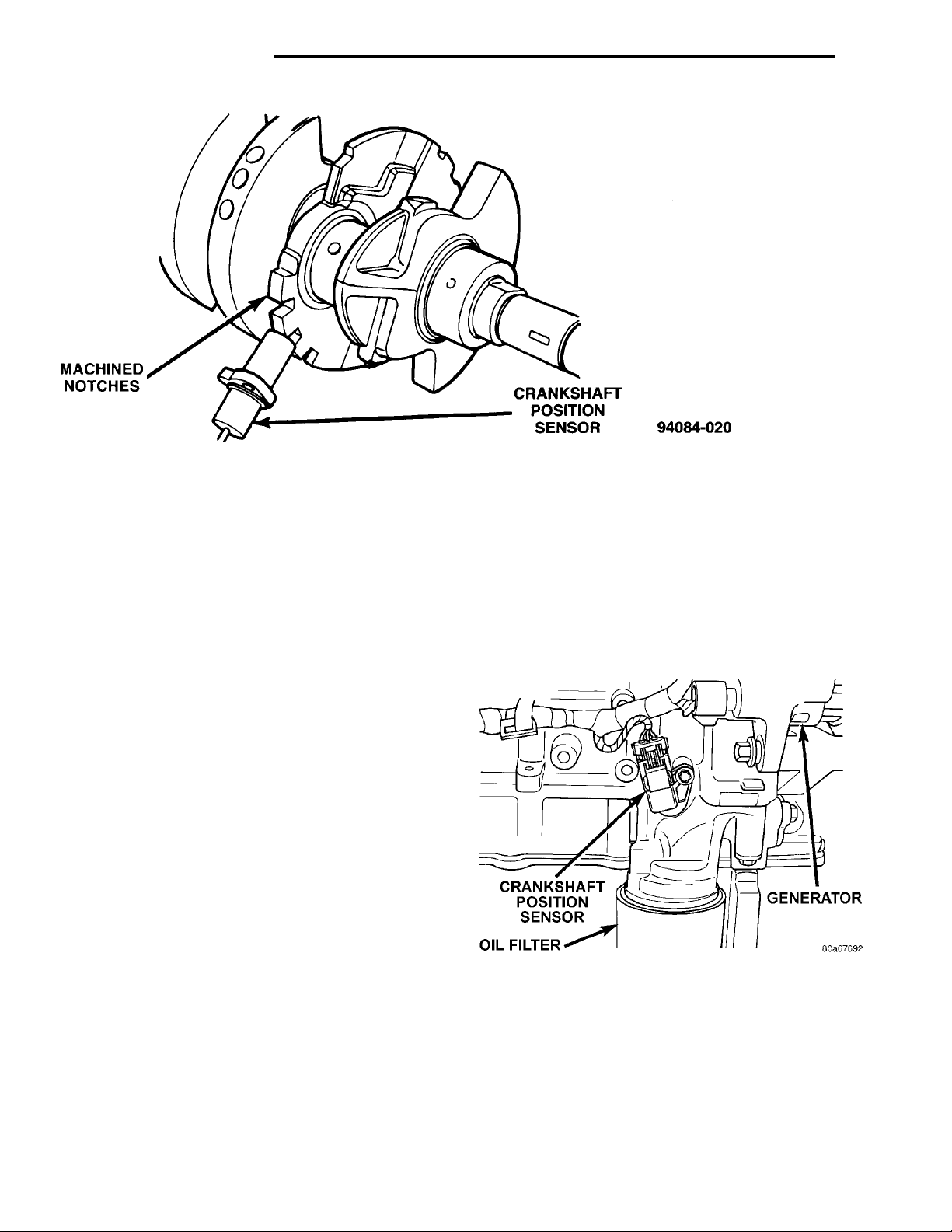
Fig. 6 Timing Reference Notches
weight has machined into it two sets of four timing
reference notches including a 60 degree signature
notch (Fig. 6). From the crankshaft position sensor
input the PCM determines engine speed and crankshaft angle (position).
The notches generate pulses from high to low in
the crankshaft position sensor output voltage. When
a metal portion of the counterweight aligns with the
crankshaft position sensor, the sensor output voltage
goes low (less than 0.5 volts). When a notch aligns
with the sensor, voltage goes high (5.0 volts). As a
group of notches pass under the sensor, the output
voltage switches from low (metal) to high (notch)
then back to low.
If available, an oscilloscope can display the square
wave patterns of each voltage pulse. From the frequency of the output voltage pulses, the PCM calculates engine speed. The width of the pulses represent
the amount of time the output voltage stays high
before switching back to low. The period of time the
sensor output voltage stays high before switching
back to low is referred to as pulse-width. The faster
the engine is operating, the smaller the pulse-width
on the oscilloscope.
By counting the pulses and referencing the pulse
from the 60 degree signature notch, the PCM calculates crankshaft angle (position). In each group of
timing reference notches, the first notch represents
69 degrees before top dead center (BTDC). The second notch represents 49 degrees BTDC. The third
notch represents 29 degrees. The last notch in each
set represents 9 degrees before top dead center
BTDC.
The timing reference notches are machined at 20°
increments. From the voltage pulse-width the PCM
tells the difference between the timing reference
notches and the 60 degree signature notch. The 60
degree signature notch produces a longer pulse-width
than the smaller timing reference notches. If the
camshaft position sensor input switches from high to
low when the 60 degree signature notch passes under
the crankshaft position sensor, the PCM knows cylinder number one is the next cylinder at TDC.
The crankshaft position sensor mounts to the
engine block behind the generator, just above the oil
filter (Fig. 7).
Fig. 7 Crankshaft Position Sensor
CAMSHAFT POSITION SENSOR
The PCM determines fuel injection synchronization
and cylinder identification from inputs provided by
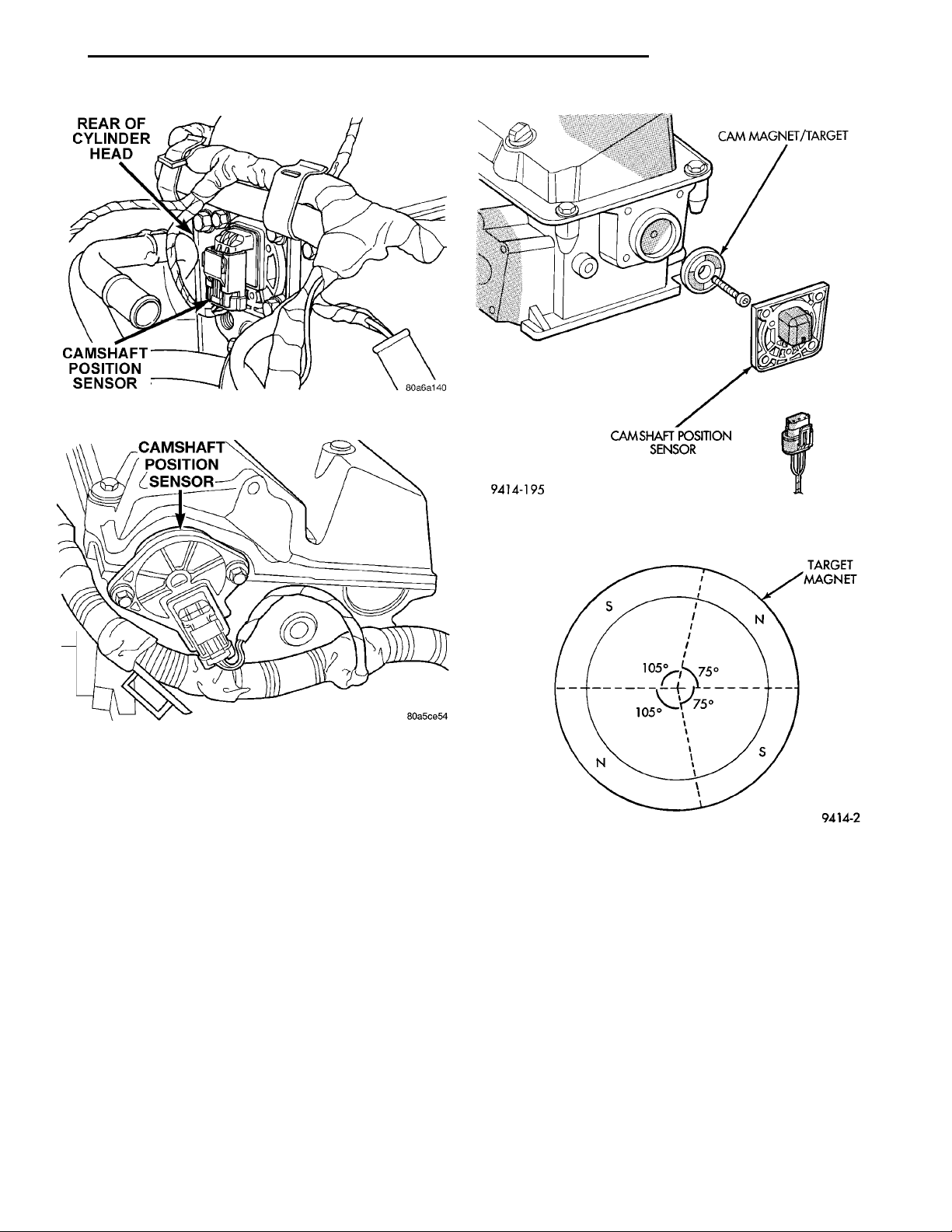
the camshaft position sensor (Fig. 8) or (Fig. 9) and
crankshaft position sensor. From the two inputs, the
PCM determines crankshaft position.
The camshaft position sensor attaches to the rear
of the cylinder head (Fig. 10). A target magnet
Page 5
REAR OF CYLINDER HEADCAMSHAFT POSITION SEN-SOR
CAMSHAFT POSITION SEN-SOR
CAM MAGNET/TARGETCAMSHAFT POSITION SEN-SOR
TARGETMAGNET
PL IGNITION SYSTEM 8D - 5
DESCRIPTION AND OPERATION (Continued)
Fig. 8 Camshaft Position Sensor—SOHC
Fig. 9 Camshaft Position Sensor—DOHC
attaches to the rear of the camshaft and indexes to
the correct position. The target magnet has four different poles arranged in an asymmetrical pattern. As
the target magnet rotates, the camshaft position sensor senses the change in polarity (Fig. 11). The sensor input switches from high (5 volts) to low (0.30
volts) as the target magnet rotates. When the north
pole of the target magnet passes under the sensor,
the output switches high. The sensor output switches
low when the south pole of the target magnet passes
underneath.
The camshaft position sensor is mounted to the
rear of the cylinder head. The sensor also acts as a
thrust plate to control camshaft endplay on SOHC
engines.
Fig. 10 Target Magnet —Typical
Fig. 11 Target Magnet Polarity
COMBINATION ENGINE COOLANT TEMPERATURE SENSOR
The coolant temperature sensor provides an input
voltage to the PCM and a separate input voltage to
the temperature gauge on the instrument panel. The
PCM determines engine coolant temperature from
the coolant temperature sensor. As coolant temperature varies, the coolant temperature sensor resistance changes resulting in a different input voltage
to the PCM.
Page 6
8D - 6 IGNITION SYSTEM PL
DESCRIPTION AND OPERATION (Continued)
When the engine is cold, the PCM will demand
slightly richer air-fuel mixtures and higher idle
ENGINE COOLANTTEMPERATURESENSORCAMSHAFTPOSITIONSENSOR
FUEL RAIL
COOLANT TEMPER-ATURE SENSOR
MAP/AIR TEMPERATURESENSORPCV VACUUM NIPPLEINTAKE MANIFOLD
and Intake Air Temperature (IAT) functions into one
sensor (Fig. 14) or (Fig. 15).
speeds until normal operating temperatures are
reached.
SOHC
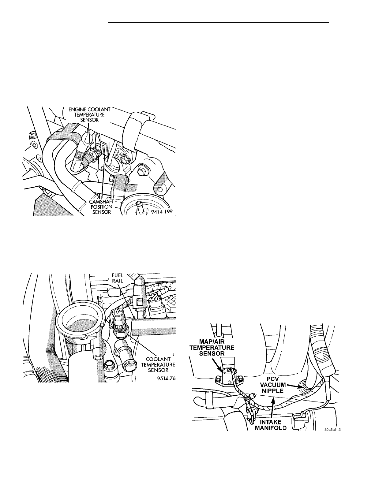
The coolant sensor threads into the end of the cyl-
inder head, next to the camshaft position sensor (Fig.
12). New sensors have sealant applied to the threads.
KNOCK SENSOR
The knock sensor threads into the side of the cylinder block in front of the starter motor. When the
knock sensor detects a knock in one of the cylinders,
it sends an input signal to the PCM. In response, the
PCM retards ignition timing for all cylinders by a
scheduled amount.
Knock sensors contain a piezoelectric material
which constantly vibrates and sends an input voltage
(signal) to the PCM while the engine operates. As the
intensity of the crystal’s vibration increase, the knock
sensor output voltage also increases.
NOTE: Over or under tightening effects knock sensor performance, possibly causing improper spark
control.
MANIFOLD ABSOLUTE PRESSURE SENSOR (MAP)
The PCM supplies 5 volts to the MAP sensor. The
MAP sensor function converts intake manifold pres-
Fig. 12 Engine Coolant Temperature Sensor—SOHC
DOHC
The coolant sensor threads into the intake manifold next to the thermostat housing (Fig. 13). New
sensors have sealant applied to the threads.
sure into voltage. The PCM monitors the MAP sensor
output voltage. As vacuum increases, MAP sensor
voltage decreases proportionately. Also, as vacuum
decreases, MAP sensor voltage increases proportionately.
During cranking, before the engine starts running,
the PCM determines atmospheric air pressure from
the MAP sensor voltage. While the engine operates,
the PCM determines intake manifold pressure from
the MAP sensor voltage. Based on MAP sensor voltage and inputs from other sensors, the PCM adjusts
spark advance and the air/fuel mixture.
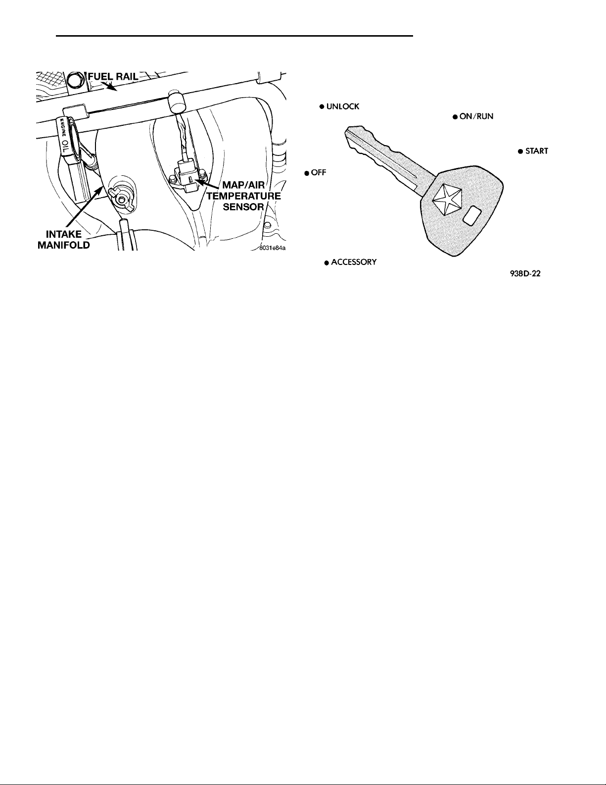
The MAP/IAT sensor mounts to the intake manifold (Fig. 14) or (Fig. 15).
Fig. 13 Engine Coolant Temperature Sensor—DOHC
INTAKE AIR TEMPERATURE SENSOR
The intake air temperature sensor measures the
temperature of the air as it enters the engine. The
sensor supplies one of the inputs the PCM uses to
determine injector pulse-width.
The MAP/Intake Air Temperature (IAT) sensor,
located on the intake manifold, combines the MAP
Fig. 14 MAP/IAT sensor—SOHC
Page 7
INTAKE MANI-FOLD MAP/AIR TEM-PERATURESENSOR
FUEL RAIL
PL IGNITION SYSTEM 8D - 7
UNLOCKOFFACCESSORY ON/RUN START
DESCRIPTION AND OPERATION (Continued)
• On/Run
• Start
Fig. 15 MAP/IAT sensor—DOHC
THROTTLE POSITION SENSOR (TPS)
The TPS mounts to the side of the throttle body.
The TPS connects to the throttle blade shaft. The
TPS is a variable resistor that provides the Powertrain Control Module (PCM) with an input signal
(voltage). The signal represents throttle blade position. As the position of the throttle blade changes,
the resistance of the TPS changes.
The PCM supplies approximately 5 volts to the
TPS. The TPS output voltage (input signal to the
powertrain control module) represents throttle blade
position. The TPS output voltage to the PCM varies
from approximately 0.38 volts to 1.2 volts at minimum throttle opening (idle) to a maximum of 3.1
volts to 4.4 volts at wide open throttle.
Along with inputs from other sensors, the PCM
uses the TPS input to determine current engine operating conditions. The PCM also adjusts fuel injector
pulse width and ignition timing based on these
inputs.
IGNITION SWITCH
In the RUN position, the ignition switch connects
power from the Power Distribution Center (PDC) to a
30 amp fuse in the fuse block, back to a bus bar in
the PDC. The bus bar feeds circuits for the Powertrain Control Module (PCM), duty cycle purge solenoid, EGR solenoid, and ABS system. The bus bar in
the PDC feeds the coil side of the radiator fan relay,
A/C compressor clutch relay, and the fuel pump relay.
It also feeds the Airbag Control Module (ACM)
LOCK KEY CYLINDER
The lock cylinder is inserted in the end of the
housing opposite the ignition switch. The ignition key
rotates the cylinder to 5 different detents (Fig. 16):
• Accessory
• Off (lock)
• Unlock
IGNITION INTERLOCK
have an interlock system. The system prevents shifting the vehicle out of Park unless the ignition lock
cylinder is in the Off, Run or Start position. In addition, the operator cannot rotate the key to the lock
position unless the shifter is in the park position. On
vehicles equipped with floor shift refer to Group 21 Transaxle for Automatic Transmission Shifter/Ignition Interlock.
DIAGNOSIS AND TESTING
TESTING FOR SPARK AT COIL—2.0/2.4L
WARNING: THE DIRECT IGNITION SYSTEMS GENERATES APPROXIMATELY 40,000 VOLTS. PERSONAL INJURY COULD RESULT FROM CONTACT
WITH THIS SYSTEM.
must be checked individually.
CAUTION: Spark plug wire damage may occur if
the spark plug is moved more than 1/4 inch away
from the engine ground.
CAUTION: Do not leave any one spark plug cable
disconnected any longer than 30 seconds or possible heat damage to catalytic converter will occur.
CAUTION: Test must be performed at idle and in
park only with the parking brake on.
Fig. 16 Ignition Lock Cylinder Detents
All vehicles equipped with automatic transaxles
The coil pack contains independent coils. Each coil
Page 8
8D - 8 IGNITION SYSTEM PL
DIAGNOSIS AND TESTING (Continued)
SPARK PLUG CABLEBOOT SPARKPLUGCHECK FORSPARK HEREA GOOD ENGINEGROUND
NOTE: New isolated engine valve cover may not
provide adequate ground. Use engine block as
engine ground.
Use a new spark plug and spark plug cable
for the following test.
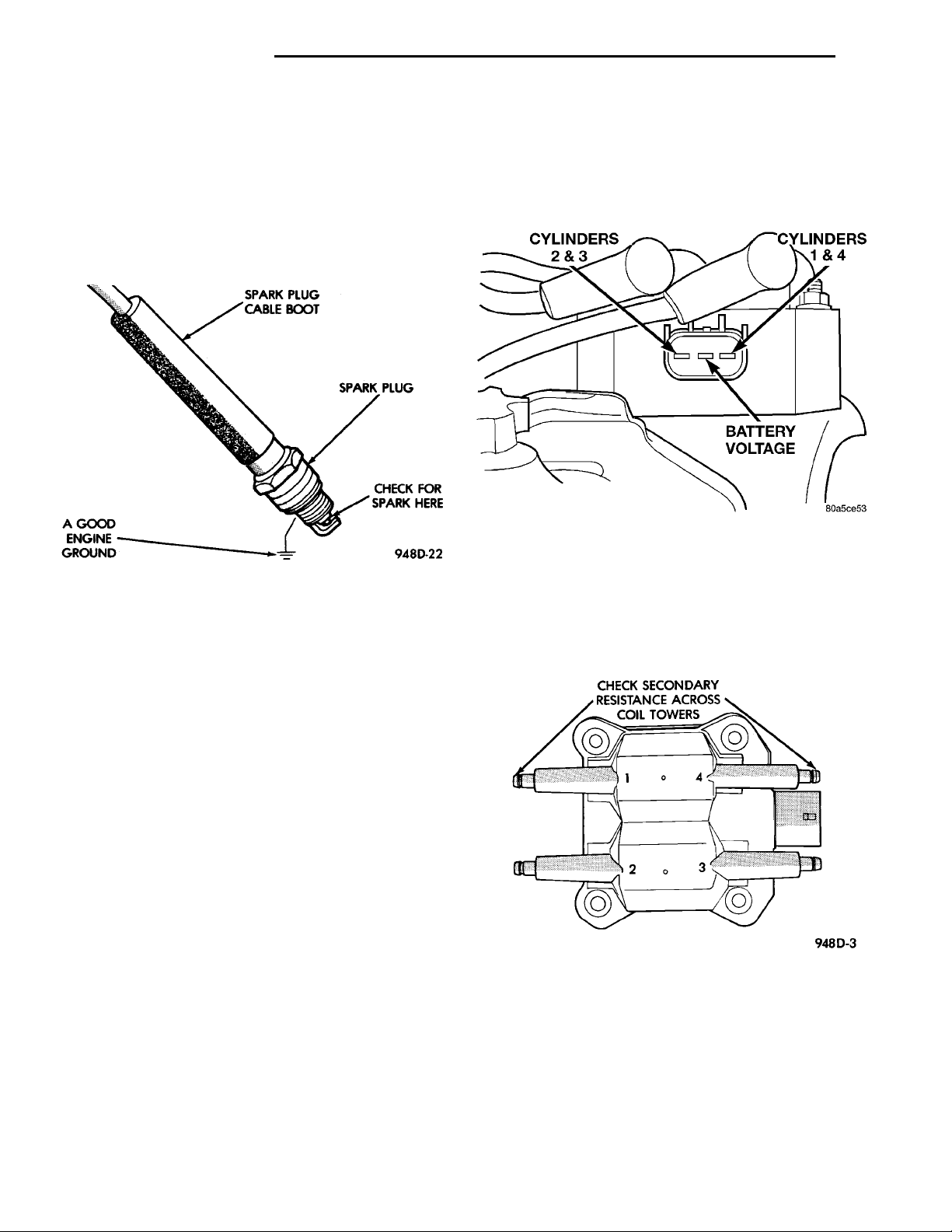
(1) Insert a new spark plug into the new spark
plug boot. Ground the plug to the engine (Fig. 17).
Do not hold with your hand.
Fig. 17 Testing For Spark
(2) Starting with coil insulator #1, remove it from
the DIS coil.
(3) Plug the test spark plug cable onto #1 coil
tower. Make sure a good connection is made; there
should be a click sound.
(4) Crank the engine and look for spark across the
electrodes of the spark plug.
CYLINDERS2&3CYLINDERS1&4BATTERY VOLTAGE
CHECK SECONDARY RESIS-TANCE ACROSS COIL TOW-ERS
(3) Measure the primary resistance of each coil. At
the coil, connect an ohmmeter between the B+ pin
and the pin corresponding to the cylinders in question (Fig. 18). Resistance on the primary side of each
coil should be 0.45 - 0.65 ohm. Replace the coil if
resistance is not within tolerance.
Fig. 18 Terminal Identification
(4) Remove ignition cables from the secondary towers of the coil. Measure the secondary resistance of
the coil between the towers of each individual coil
(Fig. 19). Secondary resistance should be 11,000 to
14,000 ohms. Replace the coil if resistance is not
within tolerance.
CAUTION: Always install the cable back on the coil
tower after testing to avoid damage to the coil and
catalytic converter.
(5) Repeat the above test for the remaining coils. If
there is no spark during all cylinder tests, proceed to
the Failure To Start Test.
(6) If one or more tests indicate irregular, weak, or
no spark, proceed to Check Coil Test.
CHECK COIL TEST
NOTE: Coil one fires cylinders 1 and 4, coil two
fires cylinders 2 and 3. Each coil tower is labeled
with the number of the corresponding cylinder.
(1) Remove the ignition cables and measure the
resistance of the cables. Resistance must be between
ranges shown in chart in specifcation section in this
group. Replace any cable not within tolerance.
(2) Disconnect the electrical connector from the
coil pack.
Fig. 19 Checking Ignition Coil Secondary
Resistance
FAILURE TO START TEST—2.0/2.4L
This no-start test checks the camshaft position sen-
sor and crankshaft position sensor.
Use the DRB scan tool to test the camshaft position sensor and the sensor circuits. Refer to the
appropriate Powertrain Diagnostics Procedure Man-
Page 9
IGNITION COILS CYLINDERS1&4BATTERY VOLTAGECYLINDERS2&3
PL IGNITION SYSTEM 8D - 9
DIAGNOSIS AND TESTING (Continued)
ual. Refer to the wiring diagrams section for circuit
information.
The Powertrain Control Module (PCM) supplies 8
volts to the camshaft position sensor and crankshaft
position sensor through one circuit. If the 8 volt supply circuit shorts to ground, neither sensor will produce a signal (output voltage to the PCM).
When the ignition key is turned and left in the On
position, the PCM automatically energizes the Auto
Shutdown (ASD) relay. However, the controller de-energizes the relay within one second because it has
not received a camshaft position sensor signal indicating engine rotation.
During cranking, the ASD relay will not energize
until the PCM receives a camshaft position sensor
signal. Secondly, the ASD relay remains energized
only if the controller senses a crankshaft position
sensor signal immediately after detecting the camshaft position sensor signal.
(1) Check battery voltage. Voltage should approximately 12.66 volts or higher to perform failure to
start test.
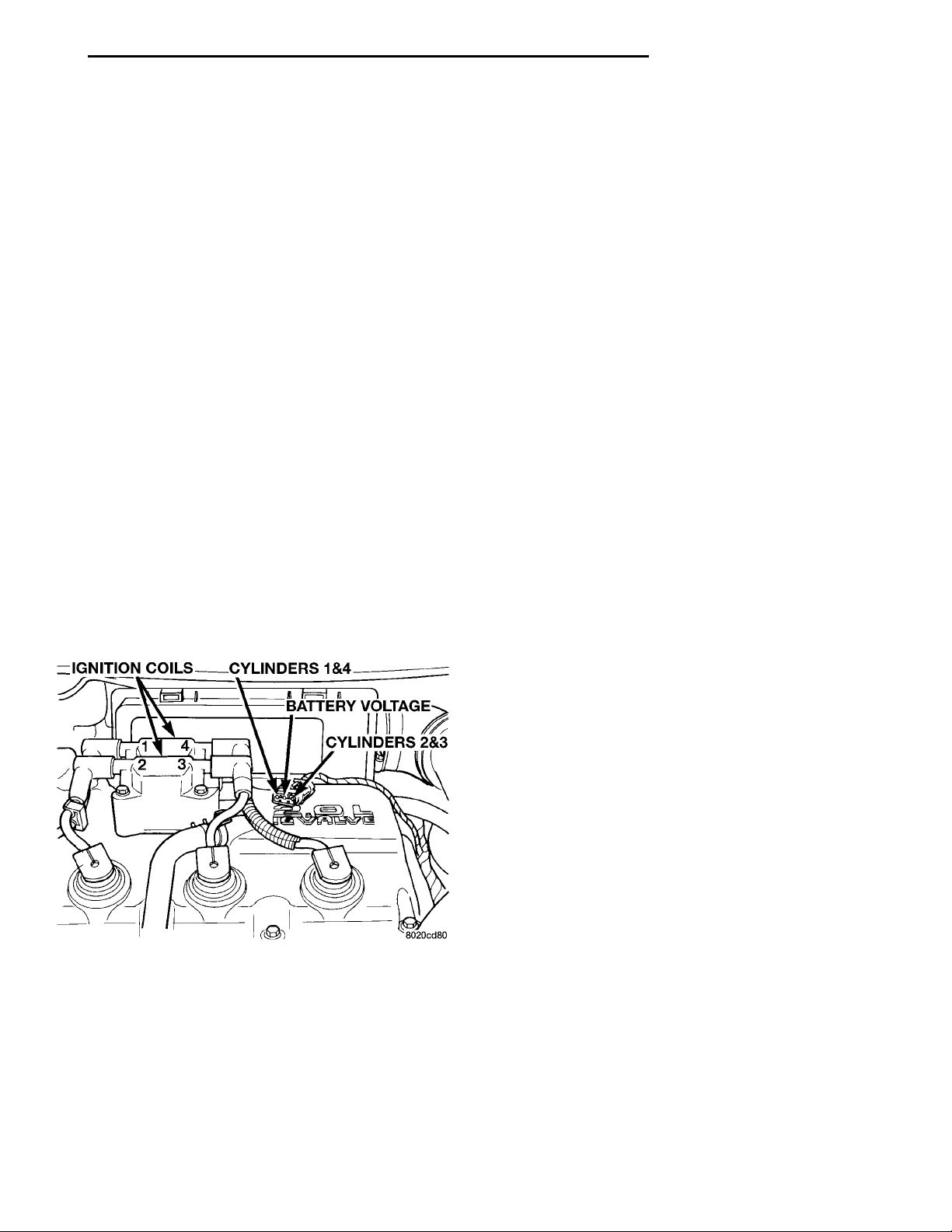
(2) Disconnect the harness connector from the coil
pack (Fig. 20).
(3) Connect a test light to the B+ (battery voltage)
terminal of the coil electrical connector and ground.
The B+ wire for the DIS coil is the center terminal.
Do not spread the terminal with the test light
probe.
priate Powertrain Diagnostics Procedure Manual.
Refer to the wiring diagrams section for circuit
information.
(5) Crank the engine. (If the key was placed in the
off position after step 4, place the key in the On position before cranking. Wait for the test light to flash
once, then crank the engine.)
(6) If the test light momentarily flashes during
cranking, the PCM is not receiving a crankshaft position sensor signal.
(7) If the test light did not flash during cranking,
unplug the crankshaft position sensor connector.
Turn the ignition key to the off position. Turn the
key to the On position, wait for the test light to
momentarily flash once, then crank the engine. If the
test light momentarily flashes, the crankshaft position sensor is shorted and must be replaced. If the
light did not flash, the cause of the no-start is in
either the crankshaft position sensor/camshaft position sensor 8 volt supply circuit, or the camshaft
position sensor output or ground circuits.
IGNITION TIMING PROCEDURE
The engines for this vehicle, use a fixed ignition
system. The PCM regulates ignition timing. Basic
ignition timing is not adjustable.
CAMSHAFT POSITION SENSOR AND CRANKSHAFT POSITION SENSOR
The output voltage of a properly operating camshaft position sensor or crankshaft position sensor
switches from high (5.0 volts) to low (0.3 volts). By
connecting an Moper Diagonostic System (MDS) and
engine analyzer to the vehicle, technicians can view
the square wave pattern.
Fig. 20 Ignition Coil Engine Harness Connector
(4) Turn the ignition key to the ON position. The
test light should flash On and then Off. Do not turn
the Key to off position, leave it in the On position .
(a) If the test light flashes momentarily, the
PCM grounded the ASD relay. Proceed to step 5.
(b) If the test light did not flash, the ASD relay
did not energize. The cause is either the relay or
one of the relay circuits. Use the DRB scan tool to
test the ASD relay and circuits. Refer to the appro-
ENGINE COOLANT TEMPERATURE SENSOR
Refer to Group 14, Fuel System for Diagnosis and
Testing.
INTAKE AIR TEMPERATURE SENSOR
Refer to Group 14, Fuel System, for Diagnosis and
Testing.
MANIFOLD ABSOLUTE PRESSURE (MAP) SENSOR TEST
Refer to Group 14, Fuel System for Diagnosis and
Testing.
THROTTLE POSITION SENSOR
To perform a complete test of the this sensor and
its circuitry, refer to the DRB scan tool and appropriate Powertrain Diagnostics Procedures manual. To
test the throttle position sensor only, refer to the following:
The Throttle Position Sensor (TPS) can be tested
with a digital voltmeter (DVM). The center terminal
of the sensor is the output terminal. One of the other
Page 10
NORMAL DRY BLACKDEPOSITS COLD (CARBON) FOULING
8D - 10 IGNITION SYSTEM PL
DIAGNOSIS AND TESTING (Continued)
terminals is a 5 volt supply and the remaining terminal is ground.
Connect the DVM between the center and sensor
ground terminal. Refer to Group 8W - Wiring Diagrams for correct pinout.
With the ignition switch in the ON position, check
the output voltage at the center terminal wire of the
connector. Check the output voltage at idle and at
Wide-Open-Throttle (WOT). At idle, TPS output voltage should be approximately 0.38 volts to 1.2 volts.
At wide open throttle, TPS output voltage should be
approximately 3.1 volts to 4.4 volts. The output voltage should gradually increase as the throttle plate
moves slowly from idle to WOT.
Check for spread terminals at the sensor and PCM
connections before replacing the TPS.
SPARK PLUG CONDITION
NORMAL OPERATING CONDITIONS
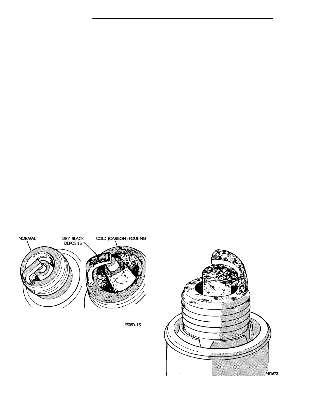
The few deposits present will be probably light tan
or slightly gray in color with most grades of commercial gasoline (Fig. 21). There will not be evidence of
electrode burning. Gap growth will not average more
than approximately 0.025 mm (.001 in) per 1600 km
(1000 miles) of operation for non platinum spark
plugs. Non-platnium spark plugs that have normal
wear can usually be cleaned, have the electrodes filed
and regapped, and then reinstalled.
CAUTION: Never attempt to file the electrodes or
use a wire brush for cleaning platinum spark plugs.
This would damage the platinum pads which would
shorten spark plug life.
Spark plug performance is not affected by MMT deposits.
COLD FOULING (CARBON FOULING)
Cold fouling is sometimes referred to as carbon fouling because the deposits that cause cold fouling are
basically carbon (Fig. 21). A dry, black deposit on one or
two plugs in a set may be caused by sticking valves or
misfire conditions. Cold (carbon) fouling of the entire set
may be caused by a clogged air cleaner.
Cold fouling is normal after short operating periods. The spark plugs do not reach a high enough
operating temperature during short operating periods. Replace carbon fouled plugs with new
spark plugs.
FUEL FOULING
A spark plug that is coated with excessive wet fuel
is called fuel fouled. This condition is normally
observed during hard start periods. Clean fuel
fouled spark plugs with compressed air and
reinstall them in the engine.
OIL FOULING
A spark plug that is coated with excessive wet oil
is oil fouled. In older engines, wet fouling can be
caused by worn rings or excessive cylinder wear.
Break-in fouling of new engines may occur before
normal oil control is achieved. Replace oil fouled
spark plugs with new ones.
OIL OR ASH ENCRUSTED
If one or more plugs are oil or ash encrusted, evaluate
the engine for the cause of oil entering the combustion
chambers (Fig. 22). Sometimes fuel additives can cause
ash encrustation on an entire set of spark plugs. Ash
encrusted spark plugs can be cleaned and reused.
Fig. 21 Normal Operation and Cold (Carbon) Fouling
Some fuel refiners in several areas of the United
States have introduced a manganese additive (MMT) for
unleaded fuel. During combustion, fuel with MMT may
coat the entire tip of the spark plug with a rust colored
deposit. The rust color deposits can be misdiagnosed as
being caused by coolant in the combustion chamber.
Fig. 22 Oil or Ash Encrusted
Page 11
GROUNDELECTRODE DEPOSITSCENTERELECTRODE
GROUNDELECTRODE CENTERELECTRODECHIPPEDINSULATOR
GROUND ELECTRODE COV-ERED WITH WHITE OR YEL-LOW DEPOSITSCENTERELEC-TRODE
PL IGNITION SYSTEM 8D - 11
DIAGNOSIS AND TESTING (Continued)
HIGH SPEED MISS
When replacing spark plugs because of a high
speed miss condition; wide open throttle opera-
tion should be avoided for approximately 80 km
(50 miles) after installation of new plugs. This
will allow deposit shifting in the combustion chamber
to take place gradually and avoid plug destroying
splash fouling shortly after the plug change.
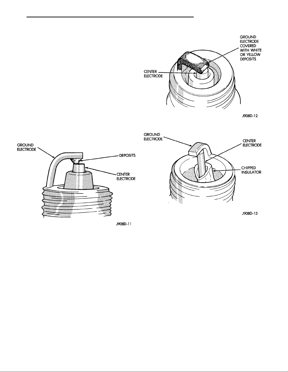
ELECTRODE GAP BRIDGING
Loose deposits in the combustion chamber can
cause electrode gap bridging. The deposits accumulate on the spark plugs during continuous stopand-go driving. When the engine is suddenly
subjected to a high torque load, the deposits partially
liquefy and bridge the gap between the electrodes
(Fig. 23). This short circuits the electrodes. Spark
plugs with electrode gap bridging can be
cleaned and reused.
Fig. 24 Scavenger Deposits
Fig. 23 Electrode Gap Bridging
SCAVENGER DEPOSITS
Fuel scavenger deposits may be either white or yellow (Fig. 24). They may appear to be harmful, but
are a normal condition caused by chemical additives
in certain fuels. These additives are designed to
change the chemical nature of deposits and decrease
spark plug misfire tendencies. Notice that accumulation on the ground electrode and shell area may be
heavy but the deposits are easily removed. Spark
plugs with scavenger deposits can be considered normal in condition, cleaned and reused.
CHIPPED ELECTRODE INSULATOR
A chipped electrode insulator usually results from
bending the center electrode while adjusting the
spark plug electrode gap. Under certain conditions,
severe detonation also can separate the insulator
from the center electrode (Fig. 25). Spark plugs
with chipped electrode insulators must be
replaced.
Fig. 25 Chipped Electrode Insulator
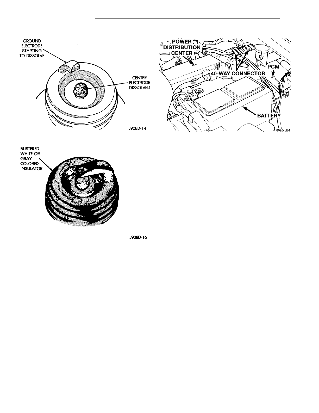
PREIGNITION DAMAGE
Excessive combustion chamber temperature can
cause preignition damage. First, the center electrode
dissolves and the ground electrode dissolves somewhat later (Fig. 26). Insulators appear relatively
deposit free. Determine if the spark plugs are the
correct type, as specified on the VECI label, or if
other operating conditions are causing engine overheating.
SPARK PLUG OVERHEATING
Overheating is indicated by a white or gray center
electrode insulator that also appears blistered (Fig.
27). The increase in electrode gap will be considerably in excess of 0.001 in per 1000 miles of operation.
This suggests that a plug with a cooler heat range
rating should be used. Over advanced ignition timing, detonation and cooling system malfunctions also
can cause spark plug overheating.
Page 12
GROUNDELECTRODESTARTING TODISSOLVE CENTERELECTRODEDISSOLVED
BLISTERED WHITE ORGRAY COLORED INSULATOR
POWER DISTRI-BUTION CEN-TER PCM40–WAY CONNECTOR BATTERY
8D - 12 IGNITION SYSTEM PL
Fig. 26 Preignition Damage
Fig. 27 Spark Plug Overheating
REMOVAL AND INSTALLATION
POWERTRAIN CONTROL MODULE (PCM)
The PCM attaches to the inner fender panel next
to the washer fluid bottle on the driver’s side (Fig.
28).
REMOVAL
(1) Disconnect negative cable from battery.
(2) Remove positive cable from battery.
(3) Remove the washer bottle neck from the rubber
grommet.
(4) Remove screws attaching PCM to body.
(5) Lift PCM up and disconnect two 40-way con-
nectors.
INSTALLATION
(1) Attach two 40-way connectors to PCM.
(2) Install PCM. Tighten mounting screws to 6.75
N·m61 N·m (60 in. lbs.6 10 in. lbs.) torque.
(3) Install washer bottle neck into the rubber
grommet.
Fig. 28 Powertrain Control Module
(4) Connect positive cable to battery.
(5) Connect negative cable to battery.
SPARK PLUG SERVICE
Failure to route the cables properly could cause the
radio to reproduce ignition noise, cross ignition of the
spark plugs or short circuit the cables to ground.
REMOVAL
REMOVE CABLES FROM COIL FIRST.
Always remove the spark plug cable by grasping
the top of the spark plug insulator, turning the boot
1/2 turn and pulling straight up in a steady motion.
(1) Remove the spark plug using a quality socket
with a rubber or foam insert.
(2) Inspect the spark plug condition. Refer to
Spark Plug Condition in this section.
INSTALLATION
(1) To avoid cross threading, start the spark plug
into the cylinder head by hand.
(2) Tighten spark plugs to 28 N·m (20 ft. lbs.)
torque.
(3) Install spark plug insulators over spark plugs.
Ensure the top of the spark plug insulator covers the
upper end of the spark plug tube.
Reconnect to coil.
SPARK PLUG CABLE SERVICE
Failure to route the cables properly could cause the
radio to reproduce ignition noise, cross ignition of the
spark plugs or short circuit the cables to ground.
REMOVAL
Remove spark plug cable from coil frist.
Always remove the spark plug cable by grasping
the top of the spark plug insulator, turning the boot
1/2 turn and pulling straight up in a steady motion.
Page 13
PL IGNITION SYSTEM 8D - 13
REMOVAL AND INSTALLATION (Continued)
INSTALLATION
Install spark plug insulators over spark plugs.
Ensure the top of the spark plug insulator covers the
upper end of the spark plug tube.The connect the
other end to coil pack. On SOHC engines, be sure
that dual plastic clip holds #1,#2 cables off of valve
cover and that PCV hose plastic clip holds #3 cable
away from metal PCV clamp and edge of air duct. On
DOHC , be sure that the plastic clip on PCV hose is
positioned so that cable clip is beneath hose, and that
#1 cable is snapped into this clip to protect it from
metal PCV clamp.
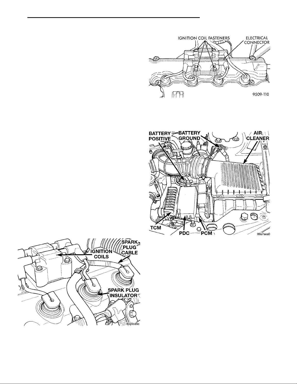
Fig. 30 Electronic Ignition Coil Pack—DOHC
SPARK PLUG TUBES
The spark plugs tubes are pressed into the cylinder
head. Sealant is applied to the end of the tube before
installation. For engine information, refer to Group
9, Engines.
of the relay within the PDC, refer to the PDC cover
for location. Check electrical terminals for corrosion
and repair as necessary.
IGNITION COIL
SOHC/DOHC
The electronic ignition coil pack attaches directly
to the valve cover (Fig. 29) or (Fig. 30).
REMOVAL
(1) Disconnect electrical connector from coil pack.
(2) Remove coil pack mounting nuts.
(3) Remove coil pack.
INSTALLATION
(1) Install coil pack on valve cover.
(2) Transfer spark plug cables to new coil pack.
The coil pack towers are numbered with the cylinder
identification. Be sure the ignition cables snap onto
the towers.
IGNITIONCOILSSPARK PLUG CABLESPARK PLUGINSULATOR
Fig. 29 Electronic Ignition Coil Pack—SOHC
AUTOMATIC SHUTDOWN RELAY
The relay is located in the Power Distribution Center (PDC) (Fig. 31). The PDC is located next to the
battery in the engine compartment. For the location
Fig. 31 Power Distribution Center (PDC)
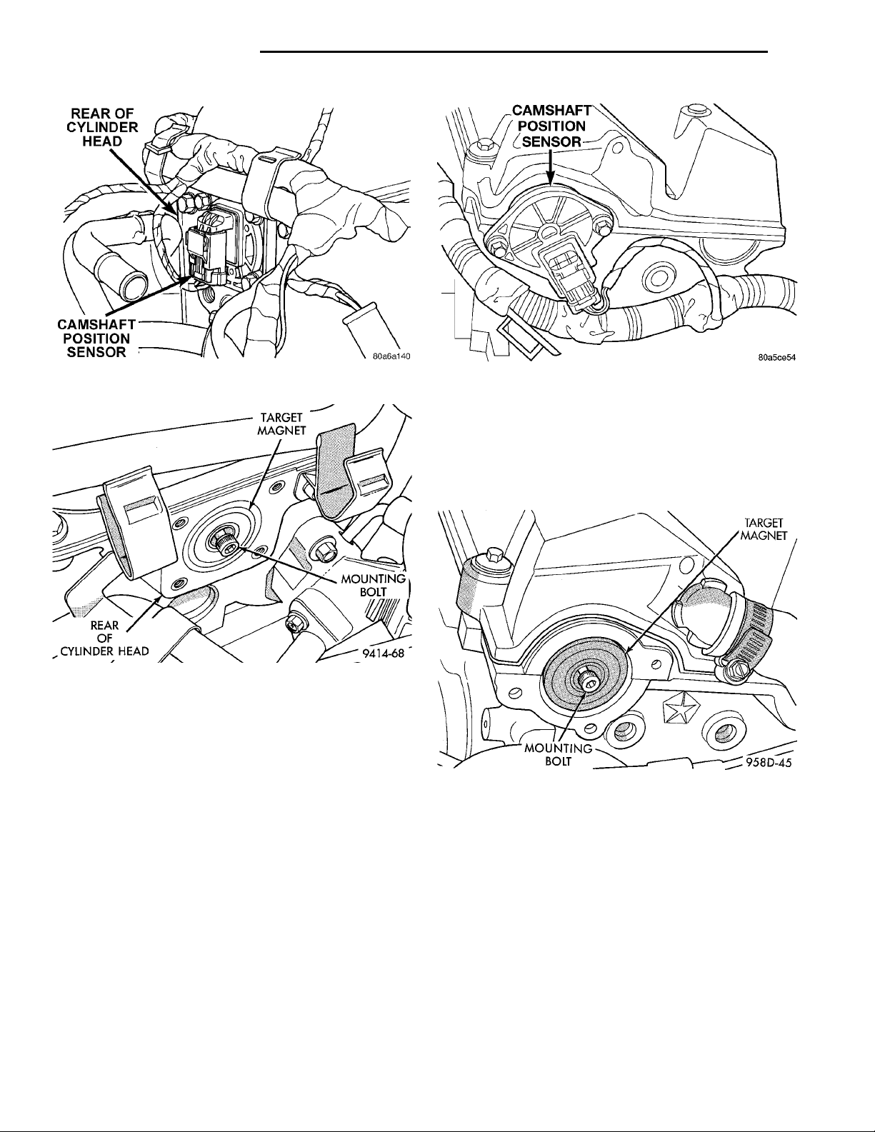
CAMSHAFT POSITION SENSOR—SOHC
The camshaft position sensor is mounted to the
rear of the cylinder head (Fig. 32).
REMOVAL
(1) Disconnect the filtered air tube from the throttle body and air cleaner housing. Remove filtered air
tube.
(2) Remove the air cleaner inlet tube.
(3) Disconnect electrical connectors from engine
coolant sensor and camshaft position sensor.
(4) Remove brake booster hose and electrical connector from holders on end of cylinder head cover.
(5) Remove camshaft position sensor mounting
screws. Remove sensor.
(6) Loosen screw attaching target magnet to rear
of camshaft (Fig. 33).
Page 14
REAR OF CYLINDER HEADCAMSHAFT POSITION SEN-SOR
TARGET MAGNETMOUNTING BOLTREAR OF CYLINDERHEAD
CAMSHAFT POSITION SEN-SOR
TARGETMAGNETMOUNTINGBOLT
8D - 14 IGNITION SYSTEM PL
REMOVAL AND INSTALLATION (Continued)
Fig. 32 Camshaft Position Sensor Location—SOHC
Fig. 33 Target Magnet Removal/Installation
INSTALLATION
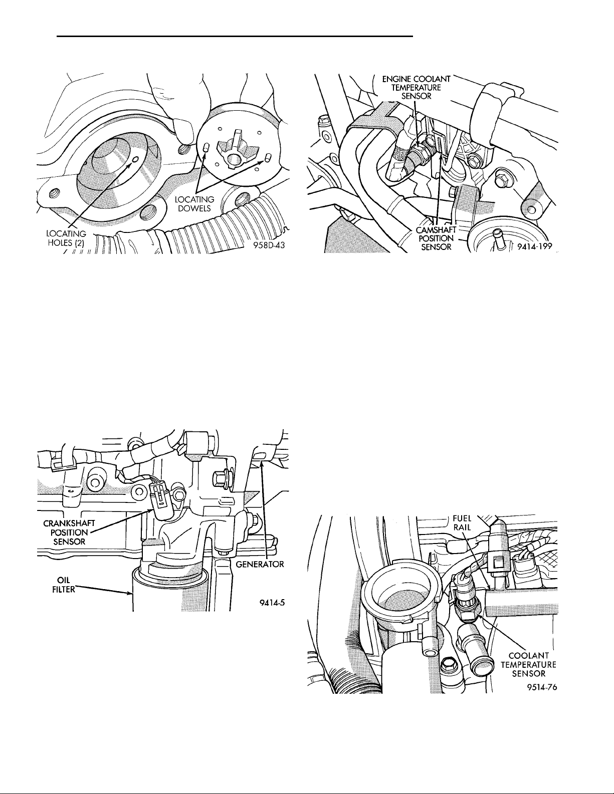
The target magnet has two locating dowels that fit
into machined locating holes in end of the camshaft.
(1) Install target magnet in end of camshaft.
Tighten mounting screw to 3.4 N·m (30 in. lbs.)
torque.
(2) Install camshaft position sensor. Tighten sensor
mounting screws to 9 N·m (80 in. lbs.) torque.
(3) Place brake booster hose and electrical harness
in holders on end of valve cover.
(4) Attach electrical connectors to coolant temperature sensor and camshaft position sensor.
(5) Install air cleaner inlet tube and filtered air
tube.
CAMSHAFT POSITION SENSOR—DOHC
The camshaft position sensor is mounted to the
rear of the cylinder head (Fig. 34).
REMOVAL
(1) Remove filtered air tube from the throttle body
and air cleaner housing.
Fig. 34 Camshaft Position Sensor Location—DOHC
(2) Disconnect electrical connector from camshaft
position sensor.
(3) Remove camshaft position sensor mounting
screws. Remove sensor.
(4) Loosen screw attaching target magnet to rear
of camshaft (Fig. 35).
Fig. 35 Target Magnet Removal/Installation
INSTALLATION
The target magnet has locating dowels that fit into
machined locating holes in the end of the camshaft
(Fig. 36).
(1) Install target magnet in end of camshaft.
Tighten mounting screw to 3 N·m (30 in. lbs.) torque.
(2) Install camshaft position sensor. Tighten sensor
mounting screws to 9 N·m (80 in. lbs.) torque.
(3) Carefully attach electrical connector to camshaft position sensor. Installation at an angle may
damage the sensor pins.
(4) Install filtered air tube. Tighten clamps to 3
N·m 61 (25 in. lbs. 65) torque.
Page 15
PL IGNITION SYSTEM 8D - 15
REMOVAL AND INSTALLATION (Continued)
Fig. 36 Target Magnet Installation
CRANKSHAFT POSITION SENSOR
The crankshaft position sensor mounts to the
engine block behind the generator, just above the oil
filter (Fig. 37).
REMOVAL
(1) Disconnect electrical connector from crankshaft
CRANKSHAFTPOSITION SEN-SOR GENER-ATOROIL FILTER
position sensor.
(2) Remove sensor mounting screw. Remove sensor.
INSTALLATION
Reverse procedure for installation.
Fig. 38 Engine Coolant Temperature Sensor
REMOVAL
(1) With the engine cold, drain the cooling system
until coolant level drops below sensor. Refer to Group
7, Cooling System.
(2) Disconnect coolant sensor electrical connector.
(3) Remove coolant sensor
INSTALLATION
(1) Install coolant sensor. Tighten sensor to 18.6
N·m (165 in. lbs.) torque.
(2) Attach electrical connector to sensor.
(3) Fill cooling system. Refer to Group 7, Cooling
System.
COMBINATION ENGINE COOLANT TEMPERATURE
FUEL RAIL
COOLANT TEMPER-ATURE SENSOR
SENSOR—DOHC
The coolant sensor threads into the intake manifold next to the thermostat housing (Fig. 39). New
sensors have sealant applied to the threads.
Fig. 37 Crankshaft Position Sensor
COMBINATION ENGINE COOLANT TEMPERATURE SENSOR—SOHC
The combination engine coolant sensor is located at
the rear of the cylinder head next to the camshaft
position sensor (Fig. 38). New sensors have sealant
applied to the threads.
Fig. 39 Engine Coolant Temperature Sensor—DOHC
Page 16
8D - 16 IGNITION SYSTEM PL
REMOVAL AND INSTALLATION (Continued)
REMOVAL
(1) With the engine cold, drain coolant until level
drops below cylinder head. Refer to Group 7, Cooling
System.
(2) Disconnect coolant sensor electrical connector.
(3) Remove coolant sensor.
INSTALLATION
(1) Install coolant sensor. Tighten sensor to 18.6
N·m (165 in. lbs.) torque.
(2) Attach electrical connector to sensor.
(3) Fill cooling system. Refer to Group 7, Cooling
System.
MAP/IAT SENSOR—SOHC
Refer to Group 14, Fuel Injection Section for
Removal/Installation.
MAP/IAT SENSOR—DOHC
Refer to Group 14, Fuel Injection Section for
Removal/Installation..
(4) Disconnect electrical connectors from ignition
switch.
(5) Remove ignition switch mounting screw (Fig.
42) with a #10 Torxt bit.
Fig. 41 Steering Column Shrouds
THROTTLE POSITION SENSOR
Refer to Group 14, Fuel Injection Section, for
Removal/Installation.
IGNITIONSWITCH LOCK CYLINDER HOUSINGRETAINING TABS
IGNITION SWITCH
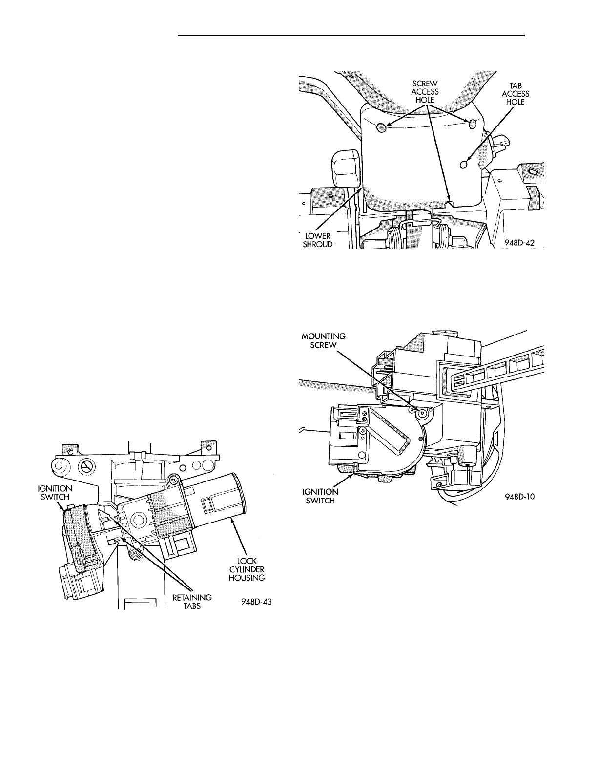
The ignition switch attaches to the lock cylinder
housing on the end opposite the lock cylinder (Fig.
40). For ignition switch terminal and circuit identification, refer to Group 8W, Wiring Diagrams.
Fig. 40 Ignition Switch—Viewed From Below
Column
REMOVAL
(1) Disconnect negative cable from battery.
(2) Place key cylinder in RUN position. Through
the hole in the lower shroud, depress lock cylinder
retaining tab and remove key cylinder (Fig. 41).
(3) Remove upper and lower shrouds from steering
column.
Fig. 42 Ignition Switch Mounting Screw
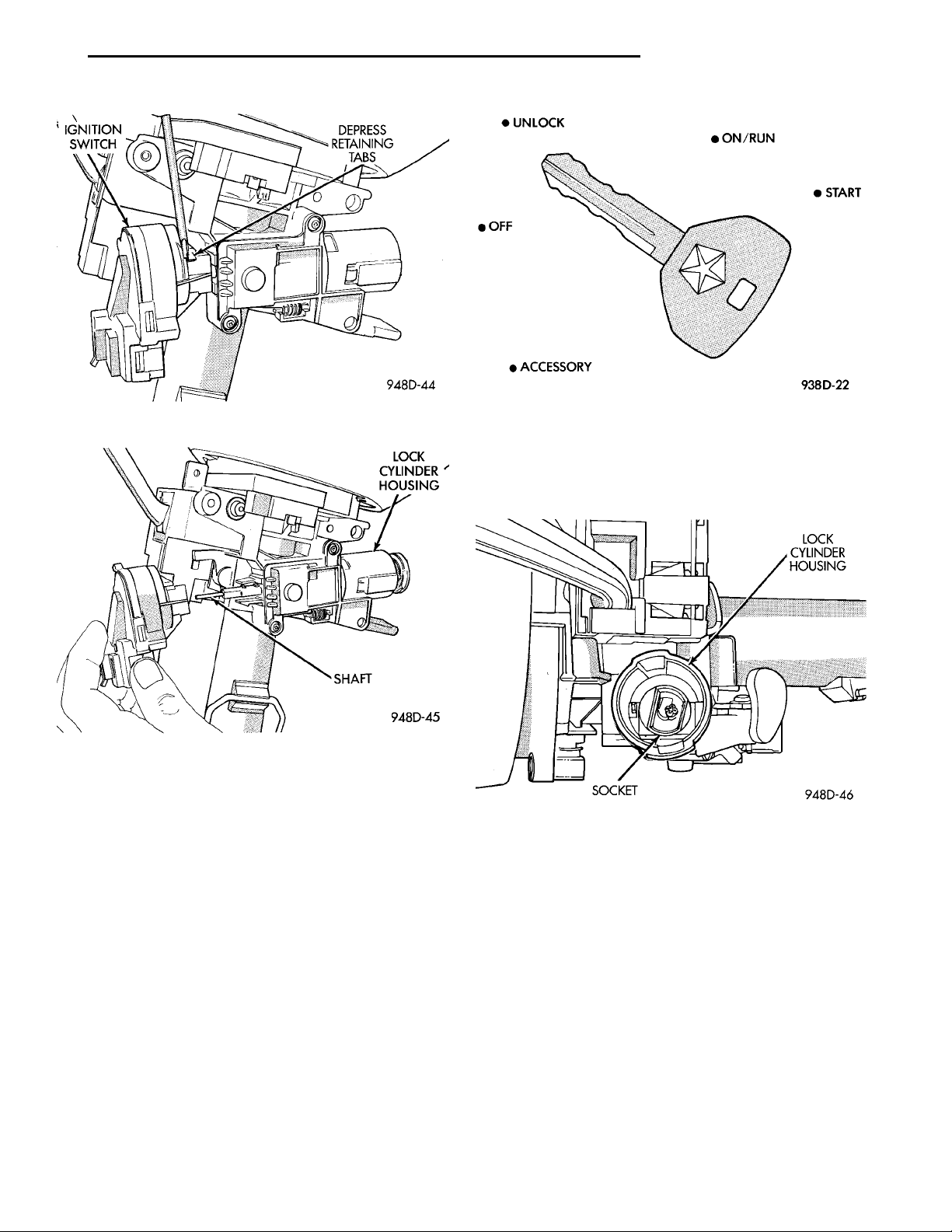
(6) Depress retaining tabs (Fig. 43) and pull igni-
tion switch from steering column.
INSTALLATION
(1) Ensure the ignition switch is in the RUN position and the actuator shaft in the lock housing is in
the RUN position.
(2) Carefully install the ignition switch. The
switch will snap over the retaining tabs (Fig. 44).
Install mounting screw (Fig. 42).
(3) Install electrical connectors to ignition switch.
(4) Install upper and lower shrouds.
(5) Install key cylinder (cylinder retaining tab will
depress only in the RUN position).
(6) Connect negative cable to battery.
(7) Check for proper operation of ignition switch
and key-in warning switch.
Page 17
DEPRESSRETAININGTABSIGNITIONSWITCH
PL IGNITION SYSTEM 8D - 17
REMOVAL AND INSTALLATION (Continued)
Fig. 43 Removing Ignition Switch
Fig. 44 Ignition Switch Installation
LOCK KEY CYLINDER
The lock cylinder is inserted in the end of the
housing opposite the ignition switch. The ignition key
rotates the cylinder to 5 different detentes (Fig. 45):
• Accessory
• Off (lock)
• Unlock
• On/Run
• Start
REMOVAL
(1) Disconnect negative cable from battery.
(2) Place key cylinder in RUN position. Through
the hole in the lower shroud, depress lock cylinder
retaining tab and remove key cylinder.
Fig. 45 Ignition Lock Cylinder Detentes
(2) The shaft at the end of the lock cylinder aligns
with the socket in the end of the housing. To align
the socket with the lock cylinder, ensure the socket is
in the Run position (Fig. 46).
Fig. 46 Socket in Lock Cylinder Housing
(3) Align the lock cylinder with the grooves in the
housing. Slide the lock cylinder into the housing
until the tab sticks through the opening in the housing.
(4) Turn the key to the Off position. Remove the
key.
(5) Connect negative cable to battery.
IGNITION INTERLOCK
Refer to Group 21, Transaxle for Shifter/Ignition
Interlock Service.
INSTALLATION
(1) Install key in lock cylinder. Turn key to run
position (retaining tab on lock cylinder can be
depressed).
LOCK CYLINDER HOUSING
Refer to Steering Column in Group 19, Steering,
for Lock Cylinder Housing Service.
Page 18
IGNITION COIL CONNECTORFRONT OF ENGINEFIRING ORDER 1–3–4–2
8D - 18 IGNITION SYSTEM PL
SPECIFICATIONS
VECI LABEL
If anything differs between the specifications found
on the Vehicle Emission Control Information (VECI)
label and the following specifications, use specifications on VECI label. The VECI label is located in the
engine compartment.
FIRING ORDER—2.0L
TORQUE SPECIFICATION
DESCRIPTION TORQUE
Camshaft Position Sensor Screw . 9 N·m (80 in. lbs.)
SOHC Cam Magnet/Target ....3.4N·m(30in.lbs.)
DOHC Cam Magnet/Target .....3N·m(30in.lbs.)
Crankshaft Position Sensor Screw . 9 N·m (80 in. lbs.)
Coolant Temp. Sensor ......18.6 N·m (165 in. lbs.)
Ignition Coil to Cyl. Head ....22N·m(200 in. lbs.)
Ignition Coil Bracket Nuts ....22N·m(200 in. lbs.)
Knock Sensor ...............10N·m(90in.lbs.)
MAP/IAT Sensor Plastic Manifold . 2 N·m (20 in. lbs.)
MAP/IAT Sensor Aluminum Manifold . 3 N·m (30 in.
lbs.)
Spark Plugs ................28N·m(20ft.lbs.)
SPARK PLUG CABLE RESISTANCE—SOHC
CABLE RESISTANCE
#1,#4 3500 ohms—
4900 ohms
#2,#3 2950 ohms—
4100 ohms
SPARK PLUG CABLE RESISTANCE—DOHC
CABLE RESISTANCE
#1,#4 3050 ohms—
4250 ohms
#2,#3 2300 ohms—
3300 ohms
SPARK PLUG
Engine Spark Plug Gap Thread Size
2.0L RC9YC 0.033 TO 0.038 14mm (3/4 in.) reach
IGNITION COIL
Coil Manufacture
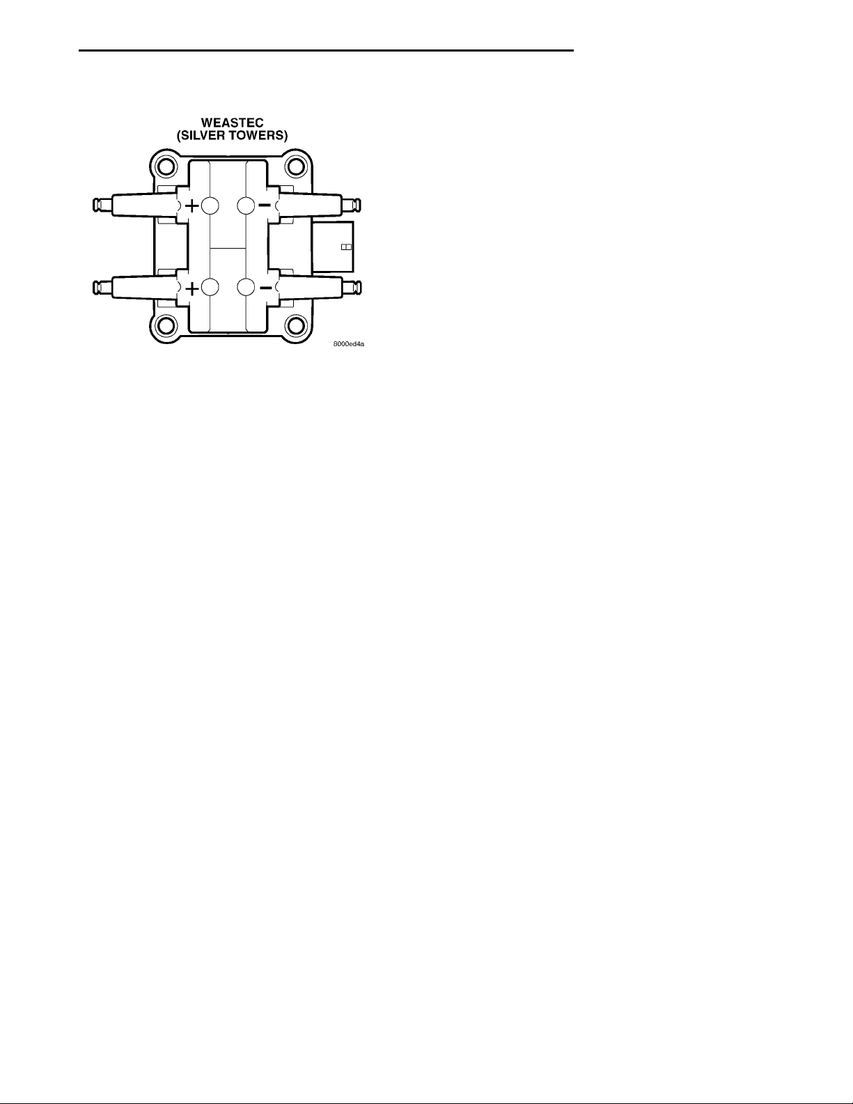
Weastec (Steel Towers) 0.45 to 0.65 Ohms 7,000 to 15,800 Ohms
Primary Resistance at 21°C-27°C
(70°F-80°F)
Secondary Resistance at 21°C-
27°C (70°F-80°F)
Page 19
WEASTEC (SILVER TOW-ERS)
PL IGNITION SYSTEM 8D - 19
SPECIFICATIONS (Continued)
Coil Polarity
Page 20

 Loading...