

Page 1

PL BATTERY 8A - 1
BATTERY
CONTENTS
page page
GENERAL INFORMATION
INTRODUCTION ........................ 1
DESCRIPTION AND OPERATION
BATTERY IGNITION OFF DRAW (IOD) ........ 1
CHARGING TIME REQUIRED .............. 2
DIAGNOSIS AND TESTING
BATTERY BUILT-IN TEST INDICATOR ........ 2
BATTERY IGNITION OFF DRAW (IOD) ........ 4
BATTERY LOAD TEST .................... 5
BATTERY OPEN CIRCUIT VOLTAGE TEST .... 6
BATTERY TEMPERATURE SENSOR ......... 6
SERVICE PROCEDURES
BATTERY CHARGING .................... 7
GENERAL INFORMATION
INTRODUCTION
The battery stores, stabilizes, and delivers electrical current to operate various electrical systems in
the vehicle. The determination of whether a battery
is good or bad is made by its ability to accept a
charge. It also must supply high-amperage current
for a long enough period to be able to start the vehicle. The capability of the battery to store electrical
current comes from a chemical reaction. This reaction takes place between the sulfuric acid solution
(electrolyte) and the lead +/- plates in each cell of the
battery. As the battery discharges, the plates react
with the acid from the electrolyte. When the charging
system charges the battery, the water is converted to
sulfuric acid in the battery. The concentration of acid
in the electrolyte is measured as specific gravity
using a hydrometer. The original equipment (OE)
battery is equipped with a hydrometer (test indicator) built into the battery cover. The specific gravity
indicates the battery’s state-of-charge. The OE battery is sealed and water cannot be added.
The battery is vented to release gases that are created when the battery is being charged and discharged. The battery top, posts, and terminals should
be cleaned when other under hood maintenance is
performed.
When the electrolyte level is below the top of the
plates, Yellow/Clear in the test Indicator, the battery
must be replaced. The battery must be completely
charged, and the battery top, posts, and cable clamps
must be cleaned before diagnostic procedures are performed.
CHARGING COMPLETELY DISCHARGED
BATTERY ............................ 7
VISUAL INSPECTION ..................... 8
REMOVAL AND INSTALLATION
BATTERY TRAY ......................... 9
BATTERY .............................. 9
FRESH AIR INLET TUBE REMOVAL ......... 10
SPECIFICATIONS
BATTERY SPECIFICATIONS .............. 10
TORQUE ............................. 10
NOTE: This group covers both Left-Hand Drive
(LHD) and Right-Hand Drive (RHD) versions of this
model. Whenever required and feasible, the RHD
versions of affected vehicle components have been
constructed as mirror-image of the LHD versions.
While most of the illustrations used in this group
represent only the LHD version, the diagnostic and
service procedures outlined can generally be
applied to either version. Exceptions to this rule
have been clearly identified as LHD, RHD, or Export
if a special illustration or procedure is required.
DESCRIPTION AND OPERATION
BATTERY IGNITION OFF DRAW (IOD)
A completely normal vehicle will have a small
amount of current drain on the battery with the key
out of the ignition. It can range from 4 to 10 milliamperes after all the modules time out. If a vehicle
will not be operated for approximately a 20 days, the
IOD fuse should be disconnected to minimize the
vehicle electrical drain on the battery. The IOD fuse
is located in the Power Distribution Center (PDC).
Refer to the PDC to locate the cover proper fuse.
Page 2
8A - 2 BATTERY PL
DESCRIPTION AND OPERATION (Continued)
CHARGING TIME REQUIRED
WARNING: NEVER EXCEED 20 AMPS WHEN
CHARGING A COLD -1°C (30°F) BATTERY. PERSONAL INJURY MAY RESULT.
The time required to charge a battery will vary
depending upon the following factors.
SIZE OF BATTERY
A completely discharged large heavy-duty battery
may require more recharging time than a completely
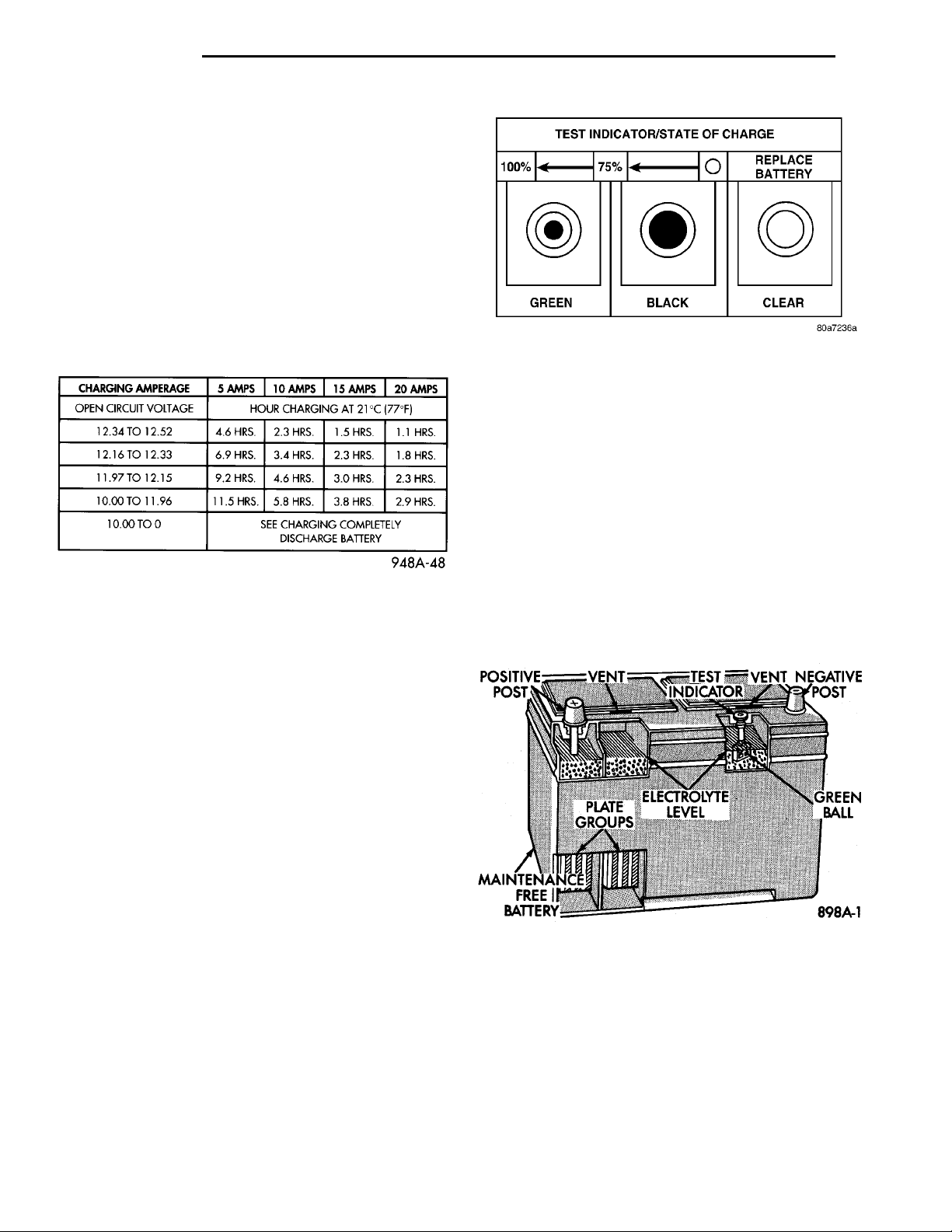
discharged small capacity battery, refer to (Fig. 1) for
charging times.
Fig. 2 Reading Test Indicator
DIAGNOSIS AND TESTING
BATTERY BUILT-IN TEST INDICATOR
USING TEST INDICATOR
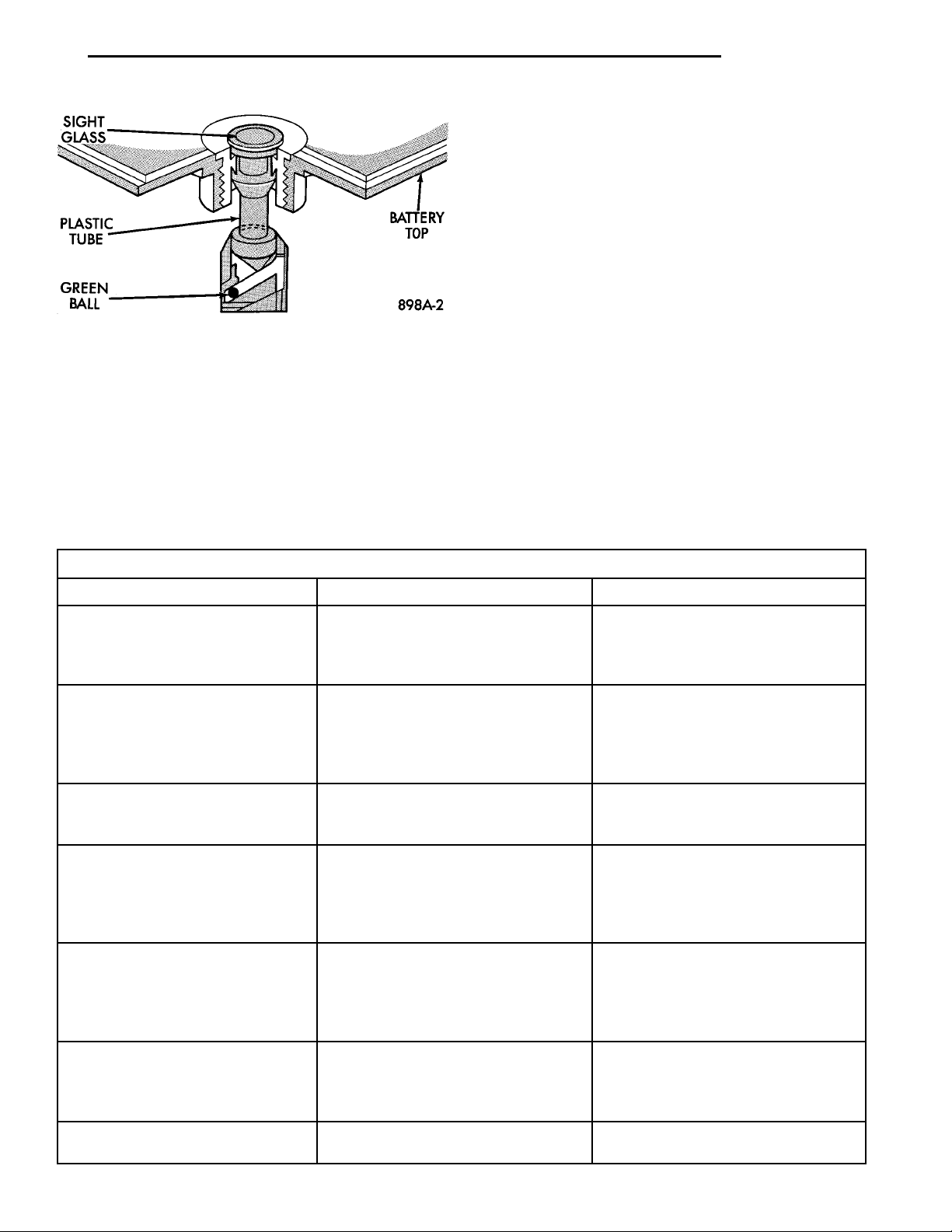
The Test Indicator (Fig. 2), (Fig. 3) and (Fig. 4)
measures the specific gravity of the electrolyte. Specific Gravity (SG) of the electrolyte will show stateof-charge (voltage). The test indicator WILL NOT
show cranking capacity of the battery. Refer to Bat-
Fig. 1 Battery Charging Time
TEMPERATURE
A longer time will be needed to charge a battery at
-18°C (0°F) than at 27°C (80°F). When a fast charger
is connected to a cold battery, current accepted by
battery will be very low at first. In time, the battery
will accept a higher rate as battery temperature
warms.
POSITIVEPOST VENT TEST INDI-CATOR VENT NEGATIVEPOST
tery Load Test for more information. Look into the
sight glass (Fig. 2), (Fig. 4) and note the color of the
indicator. Refer to the following description of colors:
NOTE: GREEN = 75 to 100% state-of-charge
PLATEGROUPS
ELECTROLYTELEVEL GREENBALLMAINTENANCEFREE BATTERY
CHARGER CAPACITY
A charger which can supply only five amperes will
require a much longer period of charging than a
charger that can supply 20 amperes or more.
STATE OF CHARGE
A completely discharged battery requires more
charging time than a partially charged battery. Electrolyte is nearly pure water in a completely discharged battery. At first, the charging current
amperage will be low. As water is converted back to
sulfuric acid inside the battery, the current amp rate
will rise. Also, the specific gravity of the electrolyte
will rise, bringing the green ball (Fig. 2) into view at
approximately 75 percent state-of-charge.
Fig. 3 Battery Construction and Test Indicator
The battery is adequately charged for further testing and may be returned to use. If the vehicle will
not crank for a maximum 15 seconds, refer to BATTERY LOAD TEST in this Group for more information.
NOTE: BLACK OR DARK=0to75%state-of-charge
The battery is INADEQUATELY charged and must
be charged until green dot is visible, (12.4 volts or
greater) before the battery is tested or returned to
Page 3
SIGHTGLASSPLASTICTUBEGREENBALL BATTERY TOP
PL BATTERY 8A - 3
DIAGNOSIS AND TESTING (Continued)
A clear color dot shows electrolyte level in battery
is below the test indicator (Fig. 2). Water cannot be
added to a maintenance free battery. The battery
must be replaced. A low electrolyte level may be
caused by an over charging condition. Refer to Generator Test Procedures on Vehicle.
CAUSES OF BATTERY DISCHARGING
It is normal to have a small 5 to 25 milliamperes
continuous electrical draw from the battery. This
draw will take place with the ignition in the OFF
position, and the courtesy, dome, storage compart-
Fig. 4 Test Indicator
use. Refer to Causes of Battery Discharging in this
Group for more information.
NOTE: CLEAR COLOR = Replace Battery
WARNING: DO NOT CHARGE, ASSIST BOOST,
LOAD TEST, OR ADD WATER TO THE BATTERY
WHEN CLEAR COLOR DOT IS VISIBLE. PERSONAL
INJURY MAY OCCUR.
ments, and engine compartment lights OFF. The continuous draw is due to various electronic features or
accessories that require electrical current with the
ignition OFF to function properly. When a vehicle is
not used over an extended period of approximately 20
days the IOD fuse should be pulled. The fuse is
located in the power distribution center. Disconnection of this fuse will reduce the level of battery discharge. Refer to Battery Diagnosis and Testing Chart
and to the proper procedures.
BATTERY DIAGNOSIS AND TESTING
STEPS POSSIBLE CAUSE CORRECTION
VISUAL INSPECTION
Check for possible damage to
battery and clean battery.
(1) Loose battery post, Cracked
battery cover or case, Leaks or Any
other physical
(2) Battery OK.
TEST INDICATOR
Check Charge Eye Color
(1) GREEN
(2) BLACK
(3) CLEAR
BATTERY OPEN CIRCUIT
VOLTAGE TEST
(1) Battery is above 12.40 Volts
(2) Battery is below 12.40 Volts.
BATTERY CHARGING (1) Battery accepted Charge.
(2) Battery will not accept charge
BATTERY LOAD TEST (1) Acceptable minimum voltage.
(2) Unacceptable minimum voltage
CHARGING A COMPLETELY
DISCHARGED BATTERY
(1) Battery accepted charge.
(2) Battery will not accept charge.
IGNITION OFF DRAW TEST (1) IOD is 5-25 Milliamperes.
(2) IOD Exceeds 25 Milliamperes.
(1) Replace Battery
(2) Check state of charge. Refer to
Test Indicator.
(1) Battery is charged. Perform
Battery 0pen Circuit Voltage Test
(2) Perform Battery Charging
procedure.
(3) Replace Battery.
(1) Perform the Battery Load Test.
(2) Perform Battery Charging
procedure.
(1) Ensure that the indicator eye is
GREEN and perform Battery 0pen
Circuit Voltage Test
(2) Perform Charging a Completely
Discharged Battery.
(1) Battery is OK to put in use,
perform Battery Ignition Off Draw
Test.
(2) Replace Battery and perform
Battery Ignition Off Draw Test.
(1) Ensure that the indicator eye is
GREEN and perform Battery 0pen
Circuit Voltage Test.
(2) Replace Battery.
(1) Vehicle is normal.
(2) Eliminate excess IOD draw.
Page 4
12 VOLT TEST LIGHTNEGATIVETERMINALNEGATIVE BATTERYPOST
8A - 4 BATTERY PL
DIAGNOSIS AND TESTING (Continued)
BATTERY BATTERYTERMINALPULLER
ABNORMAL BATTERY DISCHARGING
• Corroded battery posts, cables or terminals.
• Loose or worn generator drive belt.
• Electrical loads that exceed the output of the
charging system due to equipment or accessories
installed after delivery.
• Slow driving speeds in heavy traffic conditions
or prolonged idling with high-amperage electrical
systems in use.
• Defective electrical circuit or component causing
excess Ignition Off Draw (IOD). Refer to Battery
Ignition Off Draw (IOD).
• Defective charging system.
• Defective battery.
BATTERY IGNITION OFF DRAW (IOD)
High current draw on the battery with the ignition
OFF will discharge a battery. After a dead battery is
recharged, the vehicle ignition off draw (IOD) should
be checked. To determine if a high current draw condition exists first check the vehicle with a test lamp.
(1) Verify that all electrical accessories are OFF.
• Remove key from ignition switch
• Turn off all lights
• Trunk lid is closed
• Engine compartment hood lamp is disconnected
or lamp removed
• Glove box door is closed
• Sun visor vanity lights are OFF
• All doors are closed
• Allow the ignition key lamp system to time out
in approximately 30 seconds, if equipped.
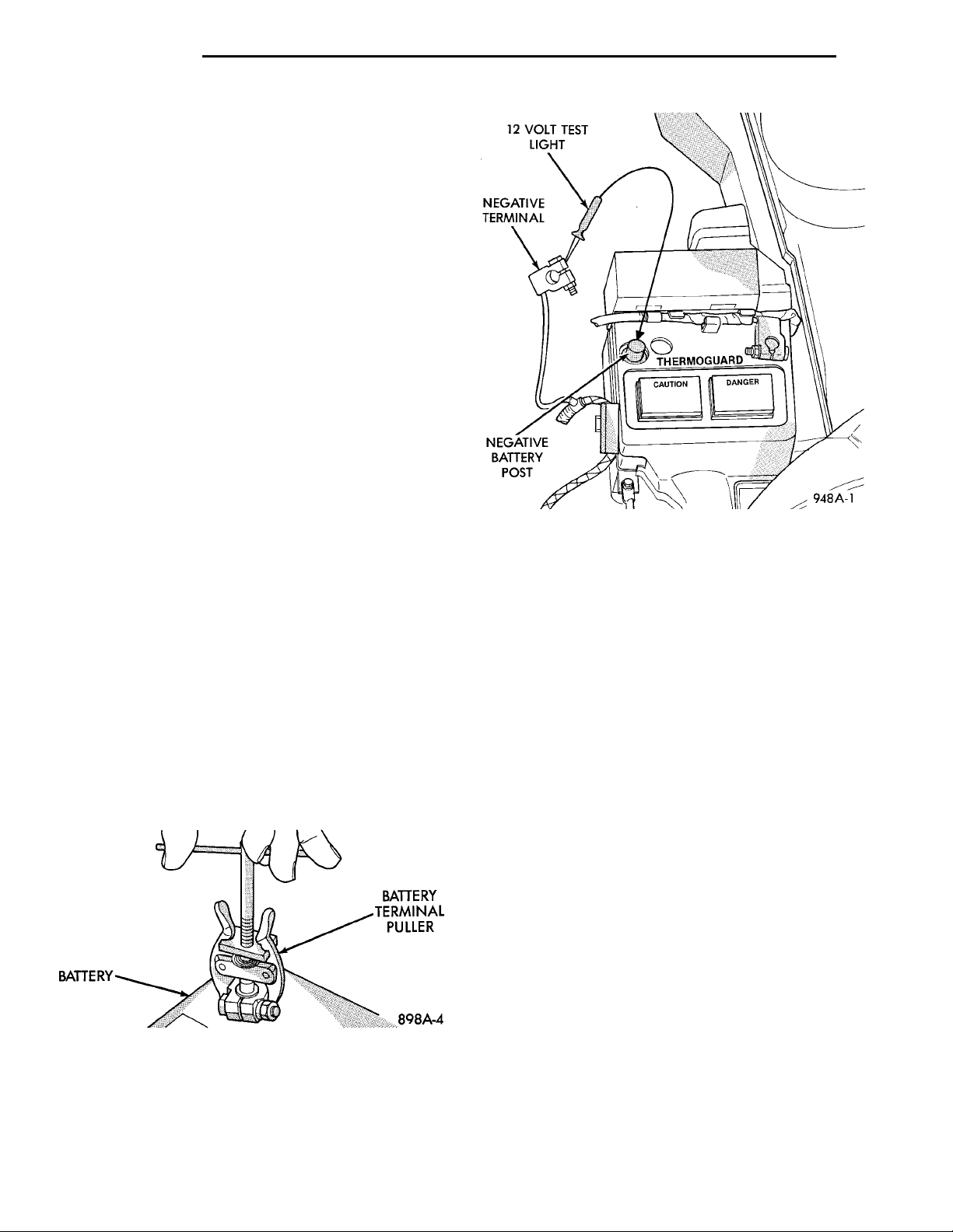
(2) Disconnect battery negative cable (Fig. 5).
(3) Connect a 12 Volt test lamp, with a cold resistance of 5-7 ohms, between the battery negative cable
clamp and the negative post (Fig. 6). If test lamp
goes out system is OK. If test lamp lights and stays
ON, go to Test Lamp Stays ON procedure.
Fig. 5 Disconnect Battery Negative Cable
TEST LAMP STAYS ON
There is either a short circuit or a fault in an electronic module. Two fuses in the Power Distribution
Center (PDC) feed the modules with ignition off
draw.
• Interior lamps fuse (10 Amp) (IOD) PDC.
• Fuel pump fuse (20 Amp) in PDC
(1) Remove interior lamp and fuel pump fuses. By
removing these fuses all ignition off draw from the
vehicle electronics will be disconnected. The test
lamp should go out. If test lamp goes out go to Step
2. If test lamp does not go out there is a current
draw or short circuit. Refer to Group 8W, Wiring Diagrams.
(2) Install the fuel pump fuse. If test lamp lights,
there is a current draw or short circuit in the A14
wiring circuit feed.
(a) Disconnect Powertrain Control Module.
(b) If test lamp goes out, replace Powertrain
Control Module.
(c) If test lamp does not go out, there is a current draw or short circuit in the A14 circuit feed.
Refer to Group 8W, Wiring Diagrams.
(3) Install the interior lamp fuse. If test lamp
lights, there is a current draw or short circuit in the
M01 circuit. Refer to Group 8W, Wiring Diagrams. If
test lamp stays out, go to Step 4
(4) Use a multi-meter that has at least a range of
200 milliamperes. Install meter between the battery
negative cable and battery negative post (Fig. 7).
Carefully remove the test lamp without disconnecting
the meter. After all modules time-out the total vehicle IOD should be less than 10 milliamperes. If ignition off draw is more than 10 milliamperes go to Step
5.
(5) Remove both fuses from the Power Distribution
Center:
• Fuel pump fuse (20 Amp)
Fig. 6 Ignition OFF (IOD) Test
Page 5
INDUCTIONAMPMETERCLAMP NEGATIVECLAMPPOSITIVECLAMP
PL BATTERY 8A - 5
DIAGNOSIS AND TESTING (Continued)
• Interior lamps fuse (10 Amp)
Fig. 7 Milliampere Meter Connection
(6) If there is any reading with fuses removed
there is a current draw or short circuit in the wiring.
Refer to Group 8W, Wiring Diagrams. If OK go to
Step 7.
(7) Install interior lamp fuse. After installing fuse,
the current can reach 250 milliamperes. After timeout the reading should not exceed 8 milliamperes. If
NOT OK go to Step 8. If OK go to Step 9.
• Ignition key lamp system
• Radio
• Remote keyless entry module, if equipped
(8) Disconnect radio and ignition switch key lamp
one component at time, to see if any component is at
fault. If the high reading is not eliminated there is a
short circuit in the wiring. Refer to Group 8W, Wiring Diagrams.
BATTERY LOAD TEST
A fully charged battery must have cranking capacity, to provide the starter motor and ignition system
enough power to start the engine over a broad range
of ambient temperatures. A battery load test will verify the actual cranking capability of the battery.
WARNING: IF BATTERY SHOWS SIGNS OF FREEZING, LEAKING, LOOSE POSTS, OR EXCESSIVELY
LOW ELECTROLYTE LEVEL, DO NOT TEST. ACID
BURNS OR AN EXPLOSIVE CONDITION MAY
RESULT.
(1) Remove both battery cables, negative cable
first. The battery top, cables and posts should be
clean. If green dot is not visible in indicator, charge
the battery. Refer to Battery Charging Procedures.
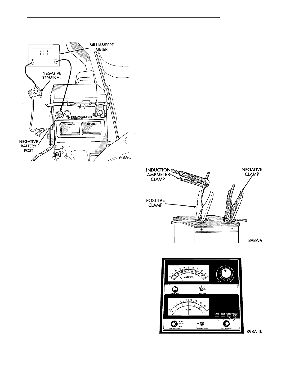
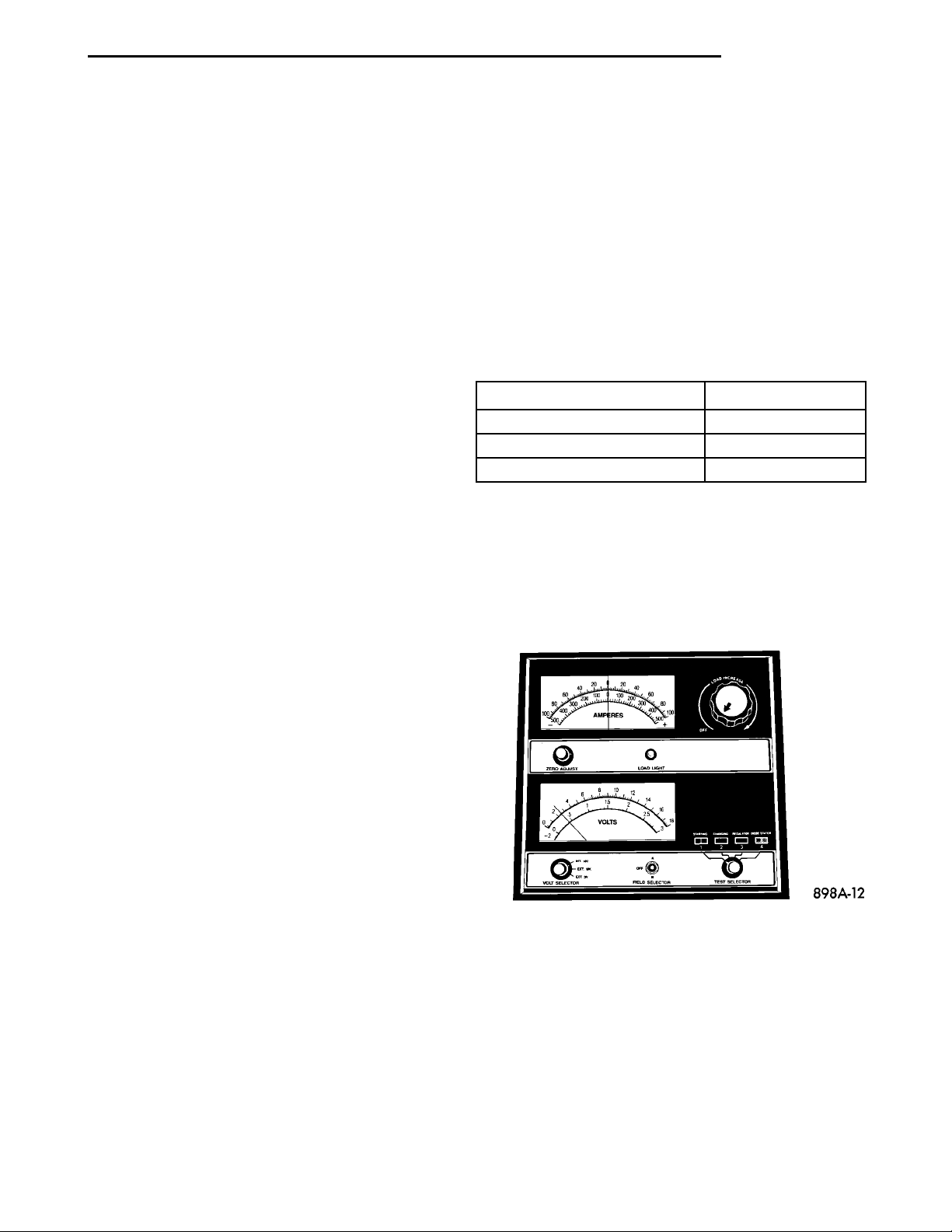
(2) Connect a Volt/Ammeter/Load tester to the battery posts (Fig. 8). Rotate the load control knob of the
Carbon pile rheostat to apply a 300 amp load. Apply
this load for 15 seconds to remove the surface charge
from the battery, and return the control knob to off
(Fig. 9).
Fig. 8 Volt-Ammeter Load Tester Connections
CAUTION: Always disconnect the meter before
opening a door.
(9) Remove interior lamps fuse and install the fuel
pump fuse. The reading should be between 1-3 milliamperes. If reading is higher than 3 milliamperes:
(a) Disconnect Powertrain Control Module.
(b) If reading drops to zero, replace Powertrain
Control Module.
(c) If reading remains the same there is a current draw or short circuit in the A14 circuit. Refer
to Group 8W, Wiring Diagrams.
Fig. 9 Remove Surface Charge From Battery
Page 6
8A - 6 BATTERY PL
DIAGNOSIS AND TESTING (Continued)
(3) Allow the battery to stabilize for 2 minutes,
and then verify open circuit voltage.
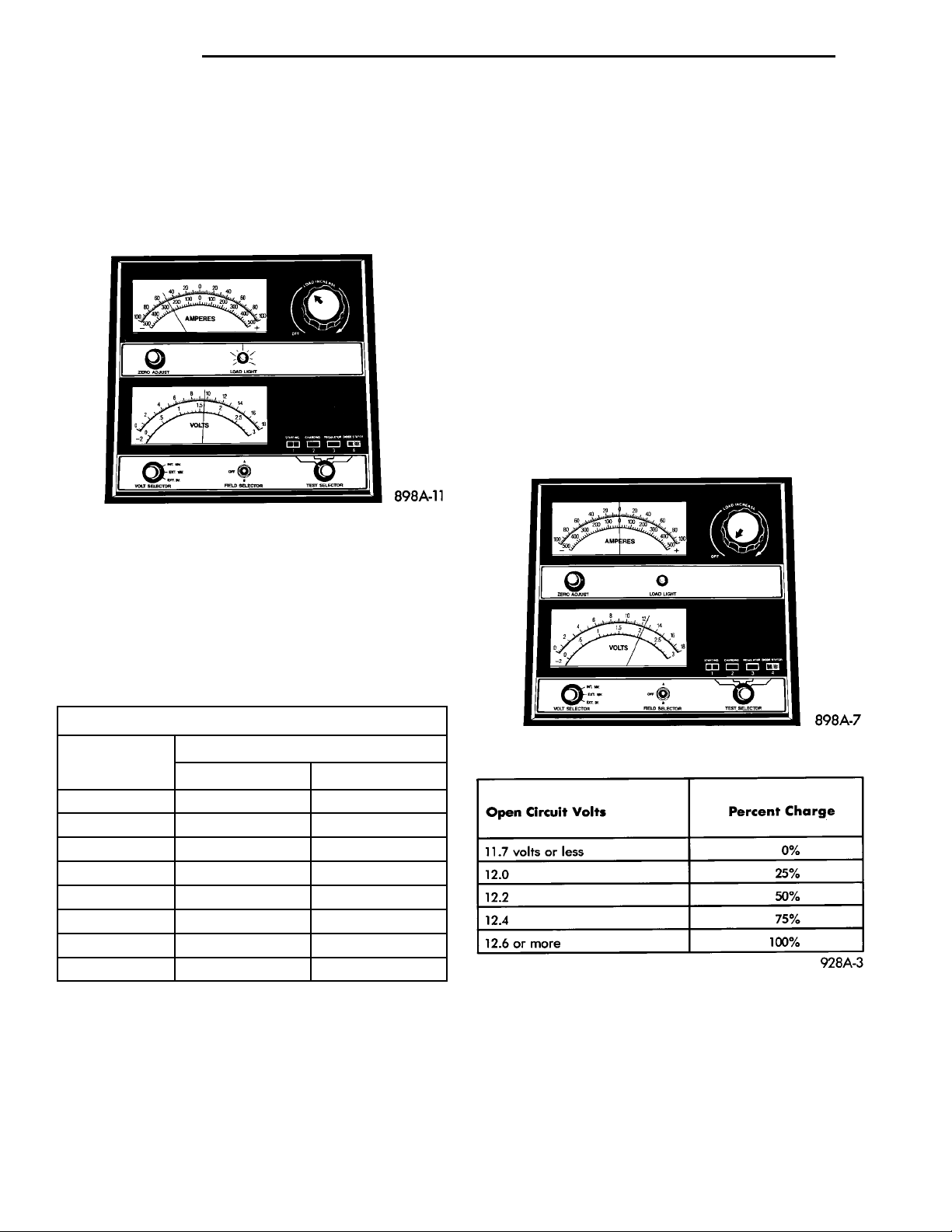
(4) Rotate the load control knob on the tester to
maintain 50% of the battery cold crank rating for 15
seconds (Fig. 10). Record the loaded voltage reading
and return the load control to off. Refer to the Battery Specifications at the rear of this Group.
Fig. 10 Load 50% Cold Crank Rating
(5) Voltage drop will vary according to battery
temperature at the time of the load test. Battery
temperature can be estimated by the temperature of
exposure over the preceding several hours. If the battery has been charged or boosted a few minutes prior
to the test, the battery would be slightly warmer.
Refer to Load Test Voltage Chart for proper loaded
voltage reading:
has open circuit voltage reading of 12.4 volts or
greater, and will not pass the load test, replace the
battery because it is defective. To test open circuit
voltage, perform the following operation.
(1) Remove both battery cables, negative cable
first. Battery top, cables and posts should be clean. If
green dot is not visible in indicator, charge the battery. Refer to Battery Charging Procedures.
(2) Connect a Volt/Ammeter/Load tester to the battery posts (Fig. 8). Rotate the load control knob of the
Carbon pile rheostat to apply a 300 amp load. Apply
this load for 15 seconds to remove the surface charge
from the battery, and return the control knob to off
(Fig. 9).
(3) Allow the battery to stabilize for 2 minutes,
and then verify the open circuit voltage (Fig. 11).
(4) This voltage reading will approximate the state
of charge of the battery. It will not reveal battery
cranking capacity (Fig. 12).
Load Test Temperature
Minimum
Voltage
9.6 volts 70° and above 21° and above
9.5 volts 60° 16°
9.4 volts 50° 10°
9.3 volts 40° 4°
9.1 volts 30° -1°
8.9 volts 20° -7°
8.7 volts 10° -12°
8.5 volts 0° -18°
(6) If battery passes load test, it is in good condition and further tests are not necessary. If it fails
load test, it should be replaced.
Temperature
°F °C
BATTERY OPEN CIRCUIT VOLTAGE TEST
An open circuit voltage no load test shows the
state of charge of a battery and whether it is ready
for a load test at 50 percent of the battery’s cold
crank rating. Refer to Battery Load Test. If a battery
Fig. 11 Testing Open Circuit Voltage
Fig. 12 Battery Open Circuit Voltage
BATTERY TEMPERATURE SENSOR
For Battery Temperature Sensor refer to Group 8C
Generator.
Page 7
PL BATTERY 8A - 7
SERVICE PROCEDURES
BATTERY CHARGING
A battery is considered fully charged when it will
meet all the following requirements.
• It has an open circuit voltage charge of at least
12.4 volts (Fig. 12).
• It passes the 15 second load test. Refer to Bat-
tery Load Test.
• The built in test indicator dot is GREEN (Fig.
2).
NOTE: The battery cannot be refilled with water, it
must be replaced.
WARNING: DO NOT CHARGE A BATTERY THAT
HAS EXCESSIVELY LOW ELECTROLYTE LEVEL.
BATTERY MAY SPARK INTERNALLY AND
EXPLODE. EXPLOSIVE GASES FORM OVER THE
BATTERY. DO NOT SMOKE, USE FLAME, OR CREATE SPARKS NEAR BATTERY. DO NOT ASSIST
BOOST OR CHARGE A FROZEN BATTERY. BATTERY CASING MAY FRACTURE. BATTERY ACID IS
POISON, AND MAY CAUSE SEVERE BURNS. BATTERIES CONTAIN SULFURIC ACID. AVOID CONTACT WITH SKIN, EYES, OR CLOTHING. IN THE
EVENT OF CONTACT, FLUSH WITH WATER AND
CALL PHYSICIAN IMMEDIATELY. KEEP OUT OF
REACH OF CHILDREN.
After the battery has been charged to 12.4 volts or
greater, perform a load test to determine cranking
capacity. Refer to Battery Load Test in this Group. If
the battery passes the load test, the battery is OK to
use. If battery will not pass the load test, it must be
replaced. Properly clean and inspect battery hold
downs, tray, terminals, cables, posts, and top before
completing service.
CHARGING COMPLETELY DISCHARGED BATTERY
The following procedure should be used to recharge
a completely discharged battery. Unless procedure is
properly followed, a good battery may be needlessly
replaced (Fig. 13).
Voltage Hours
16.0 volts or more up to 4 hrs.
14.0 to 15.9 volts up to 8 hrs.
13.9 volts or less up to 16 hrs.
Fig. 13 Charging Rate
(1) Measure the voltage at battery posts with a
voltmeter accurate to 1/10 volt (Fig. 14). If below 10
volts, charge current will be low, and it could take
some time before it accepts a current in excess of a
few milliamperes. Such low current may not be
detectable on amp meters built into many chargers.
CAUTION: Disconnect the battery NEGATIVE cable
first, before charging battery to avoid damage to
electrical systems. Lift the red battery boot cover
from the positive cable clamp. Do not exceed 16.0
volts while charging battery. Refer to the instructions supplied with charging equipment
Battery electrolyte may bubble inside of battery
case while being charged properly. If the electrolyte
boils violently, or is discharged from the vent holes
while charging, immediately reduce charging rate or
turn off charger. Evaluate battery condition. Battery
damage may occur if charging is excessive.
Some battery chargers are equipped with polarity
sensing devices to protect the charger or battery from
being damaged if improperly connected. If the battery state of charge is too low for the polarity sensor
to detect, the sensor must be bypassed for charger to
operate. Refer to operating instructions provided
with battery charger being used.
CAUTION: Charge battery until test indicator
appears green. Do not overcharge.
It may be necessary to jiggle the battery or vehicle
to bring the green dot in the test indicator into view.
Fig. 14 Voltmeter Accurate to 1/10 Volt (Connected)
(2) Connect charger leads. Some chargers feature
polarity protection circuitry that prevents operation
unless charger is connected to battery posts correctly.
A completely discharged battery may not have
enough voltage to activate this circuitry. This may
happen even though the leads are connected properly.
(3) Battery chargers vary in the amount of voltage
and current they provide. For the time required for
the battery to accept measurable charger current at
various voltages, refer to (Fig. 13). If charge current
is still not measurable after charging times, the battery should be replaced. If charge current is measur-
Page 8
BATTERYCLEANING BRUSHTEST INDICATORWARM WATER AND BAKINGSODA SOLUTION
BATTERY TEST INDICATOR BATTERY POSTCLEANERBATTERYCABLE
BATTERY CABLE CLEANINGTOOL MX75 BATTERYCABLETEST INDICA-TOR
8A - 8 BATTERY PL
SERVICE PROCEDURES (Continued)
able during charging time, the battery may be good,
and charging should be completed in the normal
manner.
VISUAL INSPECTION
CAUTION: Do not allow baking soda solution to
enter vent holes, as damage to battery can result.
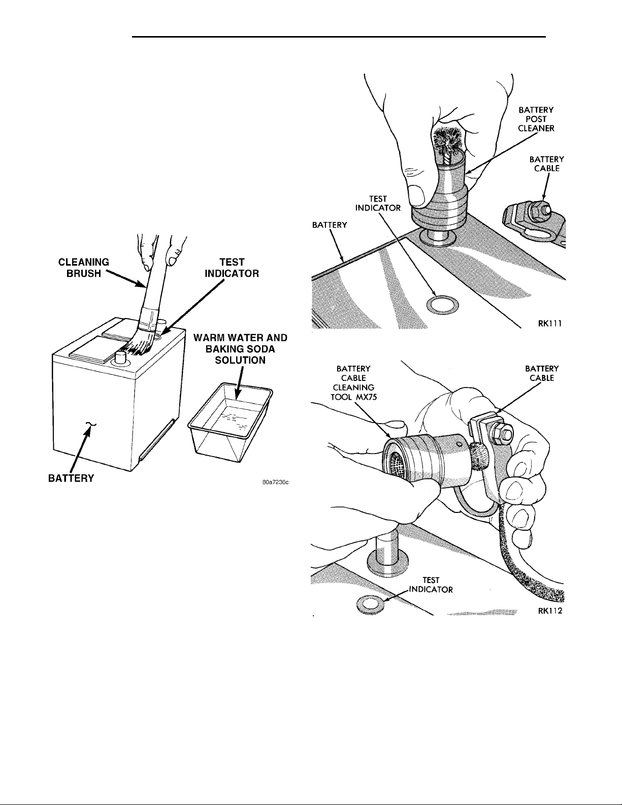
(1) Clean top of battery with a solution of warm
water and baking soda.
(2) Apply soda solution with a bristle brush and
allow to soak until acid deposits loosen (Fig. 15).
Fig. 15 Cleaning Battery
(3) Rinse soda solution from battery with clear
water and blot battery dry with paper toweling. Dispose of toweling in a safe manner. Refer to the
WARNINGS on top of battery.
(4) Inspect battery case and cover for cracks, leakage or damaged hold down ledge. If battery is damaged replace it.
(5) Inspect battery tray for damage caused by acid
from battery. If acid is present, clean area with baking soda solution.
(6) Clean battery posts with a battery post cleaning tool (Fig. 16).
(7) Clean battery cable clamps with a battery terminal cleaning tool (Fig. 17). Replace cables that are
frayed or have broken clamps.
Fig. 16 Cleaning Battery Post
Fig. 17 Cleaning Battery Cable Terminal
Page 9
AIR INTAKEDUCTBATTERY TRAYFWD
PL BATTERY 8A - 9
REMOVAL AND INSTALLATION
BATTERY
REMOVAL
(1) Make sure ignition switch is in OFF position
and all accessories are OFF.
(2) Remove battery negative cable then the positive cable (Fig. 5).
(3) Remove battery thermoguard cover (Fig. 18).
WARNING: TO PROTECT THE HANDS FROM BATTERY ACID, A SUITABLE PAIR OF HEAVY DUTY
RUBBER GLOVES, NOT THE HOUSEHOLD TYPE,
SHOULD BE WORN WHEN REMOVING OR SERVICING A BATTERY. SAFETY GLASSES ALSO SHOULD
BE WORN.
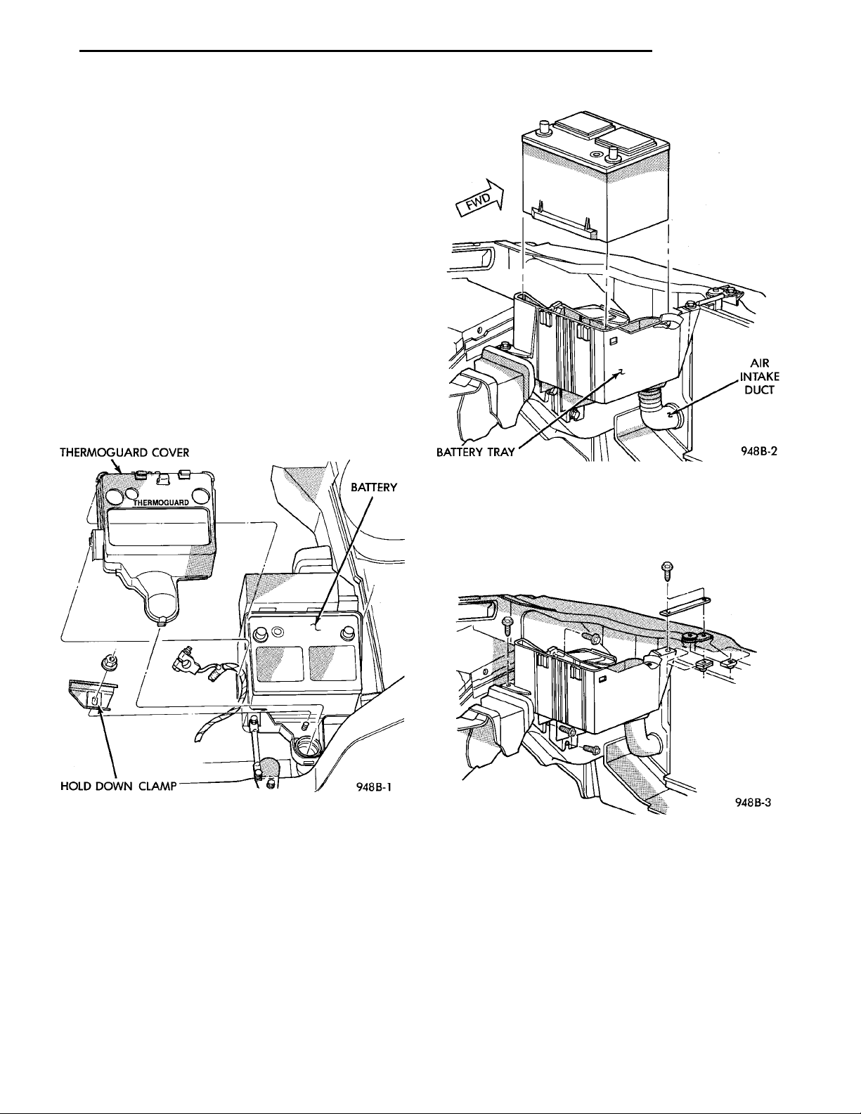
(4) Remove battery hold down clamp (Fig. 19) and
battery from vehicle.
THERMO-GUARDCOVERBATTERYHOLD DOWN CLAMP
Fig. 18 Battery Thermoguard
INSTALLATION
(1) Install battery in vehicle making sure that it is
properly positioned on battery tray.
(2) Install battery hold down clamp, making sure
that it is properly positioned on battery.
(3) Place thermoguard cover over the battery and
snap it together with battery tray (Fig. 20). The battery tray pencil strut may have to be loosened on one
end to install the thermoguard cover. After the thermoguard cover is in place, tighten pencil strut as
necessary.
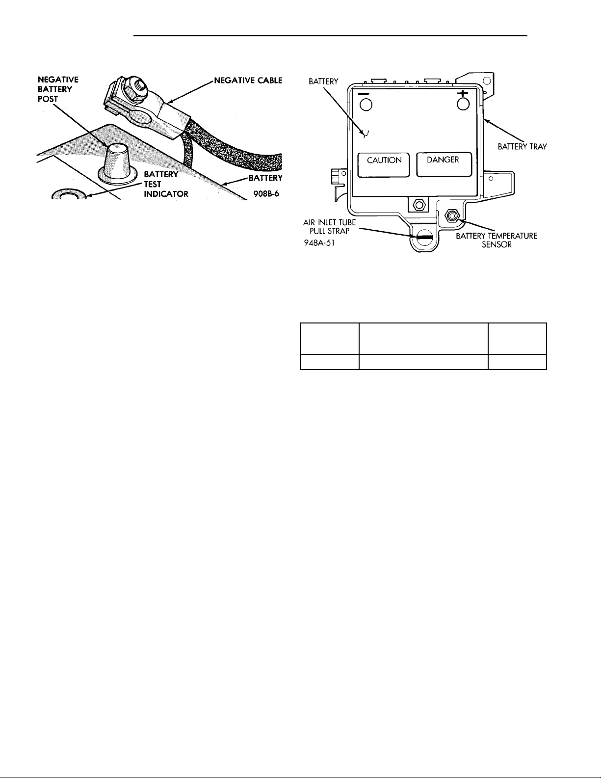
(4) Connect battery cable clamps to battery posts
and making sure top of clamp is flush or below with
Fig. 19 Battery Hold-Down
top of post (Fig. 21). Install battery positive cable
first.
(5) Tighten clamp nuts securely.
Fig. 20 Battery Tray Removal
BATTERY TRAY
REMOVAL
(1) Remove battery, refer to Battery Removal.
(2) Remove battery tray pencil strut. Remove bat-
tery tray, refer to (Fig. 20).
INSTALLATION
For installation reverse above procedures.
Page 10
NEGATIVEBATTERYPOST BATTERY TESTINDICATOR NEGATIVECABLE
8A - 10 BATTERY PL
REMOVAL AND INSTALLATION (Continued)
Fig. 21 Remove and Install Battery Cables
FRESH AIR INLET TUBE REMOVAL
REMOVAL
(1) Ensure that the ignition switch and all accessories are OFF
(2) Remove battery negative cable first then the
positive cable (Fig. 5).
(3) Remove battery thermoguard cover (Fig. 18).
WARNING: TO PROTECT THE HANDS FROM BATTERY ACID, A SUITABLE PAIR OF HEAVY DUTY
RUBBER GLOVES, NOT THE HOUSEHOLD TYPE,
SHOULD BE WORN WHEN REMOVING OR SERVICING A BATTERY. SAFETY GLASSES ALSO SHOULD
BE WORN.
(4) Squeeze the sides of the tube at the pull strap
lock tabs and push down through the hole in the battery tray (Fig. 22). DO NOT push directly down on
the pull strap itself.
(5) Remove the tube from the radiator closure
panel by squeezing the lock tabs and pushing from
the front side (Fig. 19).
SPECIFICATIONS
BATTERY SPECIFICATIONS
Load Test Cold Cranking Reserve
(Amps) Rating @ -18°C (0°F) Capacity
225 Amp 450 Amp 85 Minutes
COLD CRANK RATING
The current battery can deliver for 30 seconds and
maintain a terminal voltage of 7.2 volts or greater at
–18° C (0° F).
RESERVE CAPACITY RATING
The length of time a battery can deliver 25 amps
and maintain a minimum terminal voltage of 10.5
volts at 27°C (80°F).
Fig. 22 Air Inlet Tube Pull Strap
TORQUE
INSTALLATION
For installation reverse above procedures. Ensure
that the lock tabs are properly seated in the radiator
panel and to the bottom of battery tray (Fig. 22).
Ensure that the tube opening is properly aligned
with hole before pulling on strap.
DESCRIPTION TORQUE
Battery Hold Down Bolt
Clamp Bolt ...............9N·m(75in.lbs.)
 Loading...