

Page 1

PL COOLING 7 - 1
COOLING
CONTENTS
page page
GENERAL INFORMATION
ACCESSORY DRIVE BELTS ............... 2
AUTOMATIC TRANSMISSION OIL COOLER . . . 3
COOLANT RECOVERY SYSTEM (CRS) ....... 2
COOLANT ............................. 3
COOLING SYSTEM PRESSURE CAP ........ 3
COOLING SYSTEM ...................... 1
ENGINE BLOCK HEATER ................. 3
ENGINE THERMOSTAT ................... 3
RADIATOR ............................. 3
WATER PUMP .......................... 3
DESCRIPTION AND OPERATION
COOLANT PERFORMANCE ................ 4
COOLING SYSTEM PRESSURE CAP ........ 5
ENGINE BLOCK HEATER ................. 5
ENGINE THERMOSTAT ................... 3
RADIATOR HOSES AND CLAMPS ........... 5
WATER PUMP .......................... 6
DIAGNOSIS AND TESTING
ACCESSORY DRIVE BELT DIAGNOSIS ...... 13
COOLING SYSTEM DIAGNOSIS ............ 7
COOLING SYSTEM FLOW CHECK ......... 14
DEAERATION ......................... 16
ELECTRIC FAN MOTOR TEST ............. 14
ENGINE THERMOSTAT TESTING .......... 13
LOW COOLANT LEVEL AERATION ......... 15
PRESSURE CAP TO FILLER NECK SEAL
PRESSURE RELIEF CHECK ............. 15
PRESSURE TESTING COOLING SYSTEM
PRESSURE CAP ...................... 15
RADIATOR FAN CONTROL ............... 14
TEMPERATURE GAUGE INDICATION ....... 16
TESTING COOLING SYSTEM FOR LEAKS . . . 14
WATER PUMP DIAGNOSIS ............... 14
SERVICE PROCEDURES
ADDING ADDITIONAL COOLANT ........... 16
DRAINING COOLANT ................... 16
REFILLING COOLING SYSTEM ............ 17
ROUTINE COOLANT LEVEL CHECK ........ 16
SERVICING COOLANT LEVEL ............. 16
REMOVAL AND INSTALLATION
ACCESSORY DRIVE BELTS .............. 21
ENGINE BLOCK HEATER ................ 21
ENGINE THERMOSTAT .................. 18
RADIATOR DRAINCOCK ................. 20
RADIATOR FANS AND MOTOR ............ 20
RADIATOR ............................ 19
WATER PUMP INLET TUBE ............... 18
WATER PUMP ......................... 17
CLEANING AND INSPECTION
ACCESSORY DRIVE BELT INSPECTION ..... 22
CHEMICAL CLEANING ................... 23
CLEANING COOLING SYSTEM ............ 23
COOLING SYSTEM CAP ................. 22
RADIATOR FLUSHING ................... 23
REVERSE FLUSHING ................... 23
WATER PUMP ......................... 22
ADJUSTMENTS
BELT TENSION GAUGE METHOD .......... 23
PROPER BELT TENSION ................. 23
SPECIFICATIONS
COOLING SYSTEM CAPACITY ............ 24
TORQUE ............................. 24
SPECIAL TOOLS
COOLING ............................. 24
GENERAL INFORMATION
COOLING SYSTEM
The cooling system consists of an engine cooling
module, thermostat, coolant, a water pump to circulate the coolant. The engine cooling module may consist of a radiator, electric fan motor, fan, shroud,
coolant reserve system, transmission oil cooler, hoses,
clamps, air condition condenser and transmission oil
lines.
• When the Engine is cold: The thermostat is
closed; the cooling system has no flow through the
radiator. The coolant flows through the engine,
heater system and bypass.
• When the Engine is warm: Thermostat is open;
the cooling system has flow through radiator, engine,
heater system and bypass.
Page 2
GENERATORAIR CONDITIONING COM-PRESSOR POWER STEERING PUMP
HEATERHEAT UP COOLDOWN PRESSURE CAPTHERMOSTATHOUSING WATERPUMP ENGINECOOLANT RECOV-ERY SYSTEMTANKRADIATOR
7 - 2 COOLING PL
GENERAL INFORMATION (Continued)
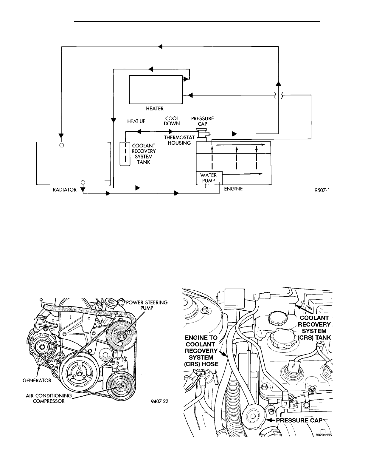
Fig. 1 Cooling System Operation
Coolant flow circuit for the 2.0L engine is shown in
(Fig. 1).
During any reassembly procedures all pipe fittings
in water jacket, and waterbox require cleaning and
application of thread sealant for entire length of
threads.
ACCESSORY DRIVE BELTS
If the engine is equipped with power steering or air
conditioning, it will have 2 drive belts. One belt
drives the generator, the other drives the Power
Steering and Air Conditioning. (Fig. 2)
trapped air. The system provides space for expansion
and contraction, and a convenient safe method for
checking and adjusting the coolant level and at atmospheric pressure without removing the pressure cap.
It also provides some reserve coolant to compensate
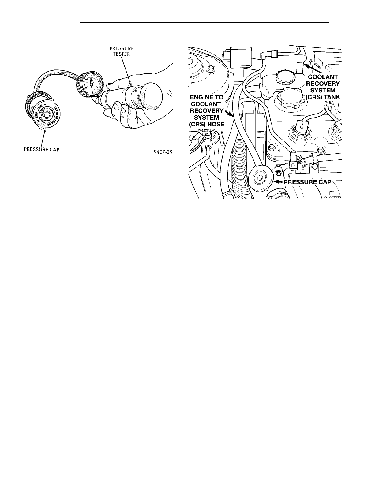
COOLANT RECOV-ERY SYSTEM(CRS) TANK PRESSURECAPENGINE TO COOLANTRECOVERY SYSTEM (CRS)HOSE
for minor leaks and evaporation or boiling losses. All
vehicles are equipped with this system (Fig. 3).
See Coolant Level Check, Service Procedures.
Deaeration and Pressure Cap sections for operation
and service.
Fig. 2 Drive Belts
COOLANT RECOVERY SYSTEM (CRS)
This system works in conjunction with the radiator
pressure cap to utilize thermal expansion and contraction of the coolant to keep the coolant free of
Fig. 3 Coolant Recovery System
Page 3
PL COOLING 7 - 3
GENERAL INFORMATION (Continued)
ENGINE THERMOSTAT
The engine thermostat is located on the front of
the engine (radiator side) in the thermostat housing/
engine outlet connector. The thermostat has an air
bleed (vent) located in the flange and a O-ring for
sealing incorporate on it. There is a relief in the thermostat housing/outlet connector for the O-ring.
WATER PUMP
The water pump has a diecast aluminum body and
housing with a stamped steel impeller. The water
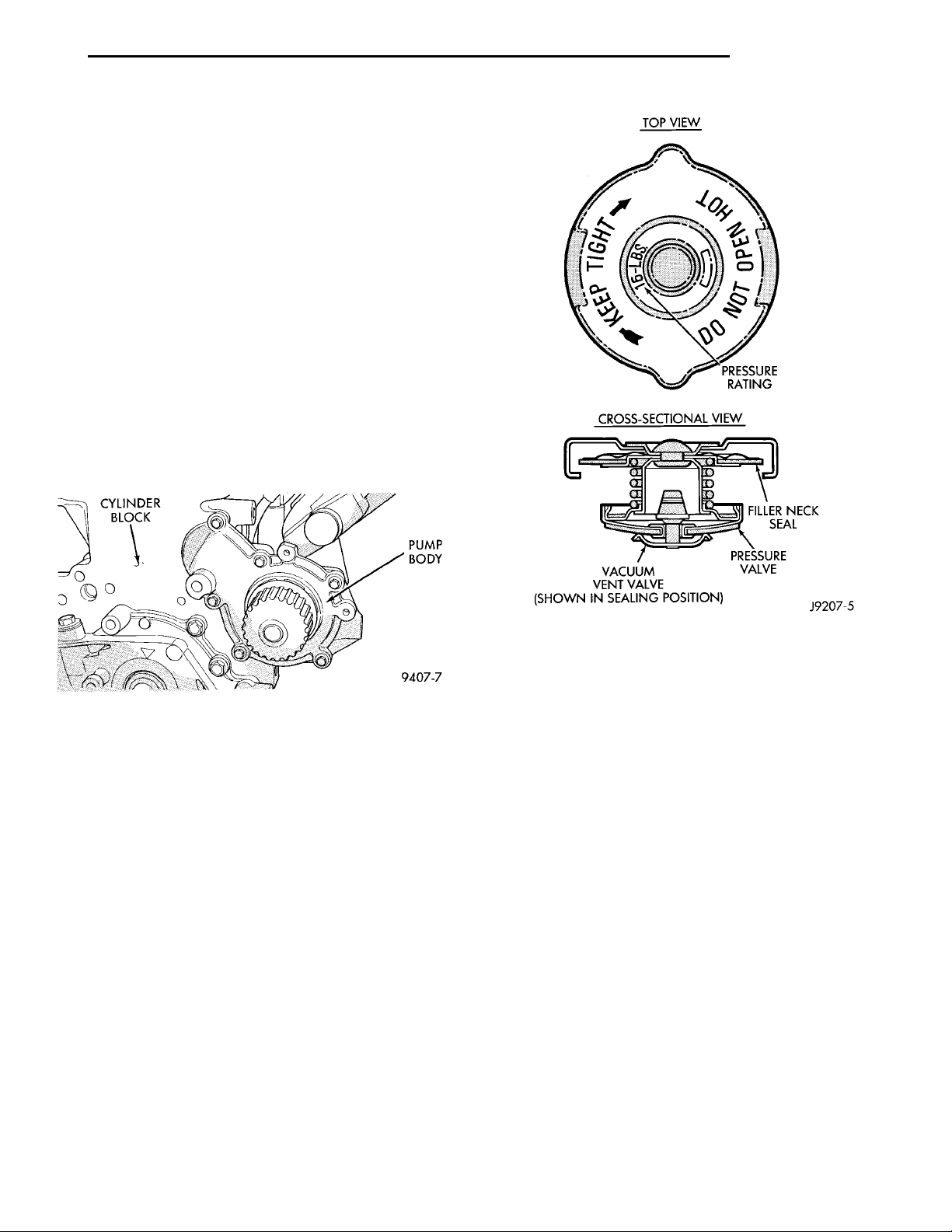
pump bolts directly to the block (Fig. 4). Cylinder
block to water pump sealing is provided by a rubber
O-ring. The water pump is driven by the timing belt.
Refer to Group 9, Engine section for component
removal to access the water pump.
NOTE: The water pump on all models can be
replaced without discharging the air conditioning
system.
Fig. 4 Water Pump
COOLANT
The cooling system is designed around the coolant.
The coolant must accept heat from engine metal, in
the cylinder head area near the exhaust valves. Then
carry this heat to the radiator where the tube/fin
assemblies of these components can give off the heat
to the air.
COOLANT REPLACEMENT
Refer to Group 0, Lubrication and Maintenance for
schedule.
COOLING SYSTEM PRESSURE CAP
The cooling system is equipped with a pressure cap
that releases pressure at some point within a range
of 97-124 kPa (14-18 psi) (Fig. 5).
The system will operate at higher than atmospheric pressure, which raises the coolant boiling
point, allowing increased radiator cooling capacity.
Fig. 5 Cooling System Pressure Cap
feed the oil cooler and the automatic transmission.
Use only approved transmission oil cooler hose. Since
these are molded to fit space available, molded hoses
are recommended. Tighten Oil Cooler Hose Clamps
to 2 N·m (18 in. lbs.).
RADIATOR
The radiator is a down-flow type (vertical tubes)
with design features that provide greater strength,
as well as sufficient heat transfer capabilities to keep
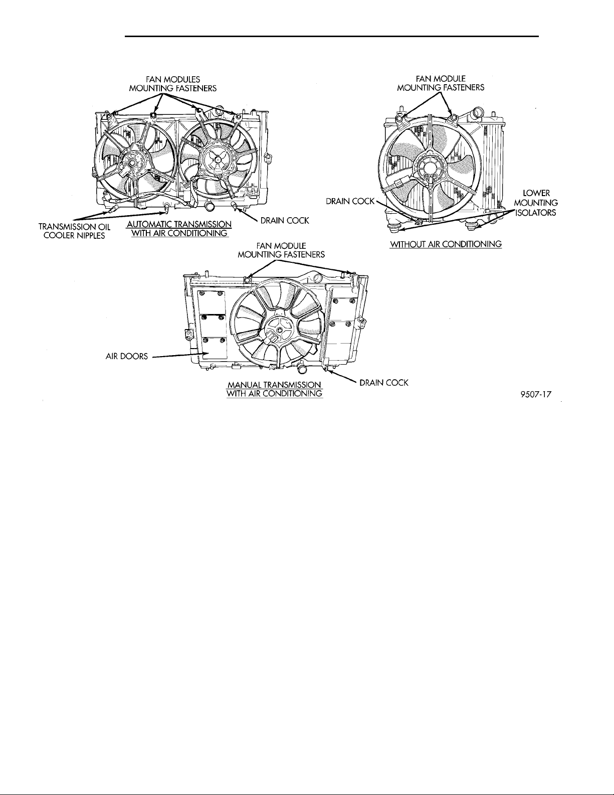
the engine satisfactorily cooled (Fig. 6).
ENGINE BLOCK HEATER
The engine block heater is available as an optional
accessory. The heater, operated by ordinary house
current (110 Volt A.C.) through a power cord and connector behind the radiator grille, provides easier
engine starting and faster warm-up when vehicle is
operated in areas having extremely low temperatures.
DESCRIPTION AND OPERATION
AUTOMATIC TRANSMISSION OIL COOLER
Oil coolers are internal oil to coolant type, mounted
in the radiator lower tank (Fig. 6). Rubber oil lines
ENGINE THERMOSTAT
The engine cooling thermostats are wax pellet
driven, reverse poppet choke type. They are designed
Page 4
TRANSMISSION OILCOOLER NIPPLES FAN MODULE MOUNTING FAS-TENERS LOWERMOUNTINGISOLATORSWITHOUT AIR CONDITIONINGDRAIN COCKFAN MODULE MOUNTING FAS-TENERSDRAIN COCKMANUAL TRANSMISSIONWITH AIR CONDITIONINGAIR DOORS
FAN MODULES MOUNTING FAS-TENERS DRAIN COCKAUTOMATIC TRANSMISSION
WITH AIR CONDITIONING
7 - 4 COOLING PL
DESCRIPTION AND OPERATION (Continued)
Fig. 6 Cooling Modules
to provide the fastest warm up possible by preventing leakage through them and to guarantee a minimum engine operating temperature of 88 to 93°C
(192 to 199°F). They also automatically reach wide
open so they do not restrict flow to the radiator as
temperature of the coolant rises in hot weather to
around 104°C (220°F). Above this temperature the
coolant temperature is controlled by the radiator, fan,
and ambient temperature, not the thermostat.
Its primary purpose is to maintain engine temperature in a range that will provide satisfactory engine
performance and emission levels under all expected
driving conditions. It also provides hot water (coolant) for heater performance. It does this by transferring heat from engine metal and automatic
transmission oil cooler (if equipped) to coolant, moving this heated coolant to the heater core and radiator, and then transferring this heat to the ambient
air.
COOLANT PERFORMANCE
Performance is measurable. For heat transfer pure
water excels (Formula = 1 btu per minute for each
degree of temperature rise for each pound of water).
This formula is altered when necessary additives to
control boiling, freezing, and corrosion are added as
follows:
• Pure Water (1 btu) boils at 100°C (212°F) and
freezes at 0°C (32°F).
• 100 Percent Glycol (.7 btu) can cause a hot
engine and detonation and will raise the freeze point
to 22°C (-8°F).
• 50/50 Glycol and Water (.82 btu) is the recommended combination that provides a freeze point of
-37°C(-35°F). The radiator, water pump, engine water
jacket, radiator pressure cap, thermostat, temperature gauge, sending unit and heater are all designed
for 50/50 glycol.
Where required, a 56 percent glycol and 44 percent
water mixture will provide a freeze point of -59°C
(-50°F).
CAUTION: Richer mixtures cannot be measured
with field equipment which can lead to problems
associated with 100 percent glycol.
SELECTION AND ADDITIVES
The use of aluminum cylinder heads, intake manifolds DOHC, and water pumps requires special corrosion protection. Mopar Antifreeze or their equivalent
are recommended for best engine cooling without corrosion. When mixed only to a freeze point of -37°C
(-35°F) to -59°C (-50°F). If it looses color or becomes
Page 5
PL COOLING 7 - 5
TOP VIEWPRESSURE RATINGCROSS-SECTIONAL VIEW FILLER NECK SEALPRESSURE VALVEVACUUM VENT VALVE (SHOWN IN SEAL-ING POSITION)
HOSE CLAMP TOOL6094 HOSECLAMP
DESCRIPTION AND OPERATION (Continued)
contaminated, drain, flush, and replace with fresh
properly mixed solution.
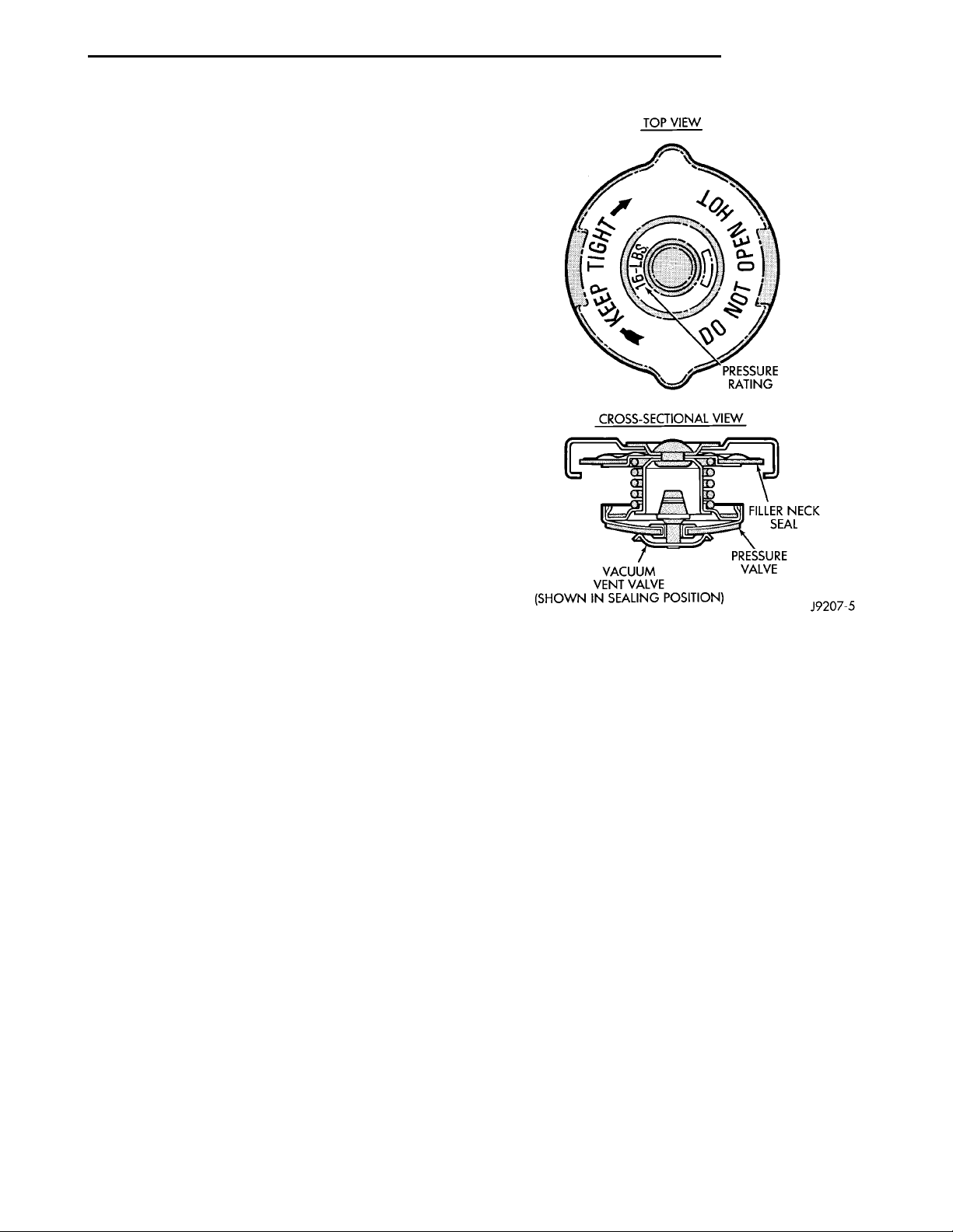
COOLING SYSTEM PRESSURE CAP
The cooling system is equipped with a pressure cap
that releases built up pressure, maintaining a range
of 97-124 kPa (14-18 psi).
The cooling system will operate at higher than
atmospheric pressure. The higher pressure raises the
coolant boiling point thus, allowing increased radiator cooling capacity.
There is a vent valve in the center of the cap that
allows a small coolant flow from the coolant reserve
system (CRS) tank. This valve is spring loaded in the
closed position. However it must be free to open during system cool-down. If the valve is stuck shut,
the radiator hoses will collapse on cool-down.
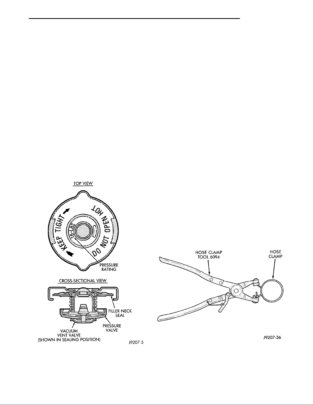
Clean the vent valve (Fig. 7) to ensure proper
sealing function.
There is a gasket in the cap that seals to the top of
the filler neck so that vacuum is maintained to draw
coolant back into the system from the coolant reserve
system (CRS) tank.
ON VEHICLE. RELIEVE PRESSURE BY PLACING A
SHOP TOWEL OVER THE CAP AND WITHOUT
PUSHING DOWN ROTATE IT COUNTERCLOCKWISE
TO THE FIRST STOP. ALLOW FLUIDS TO ESCAPE
THROUGH THE OVERFLOW TUBE AND WHEN THE
SYSTEM STOPS PUSHING OUT COOLANT AND
STEAM AND THE PRESSURE DROPS CONTINUE
SERVICE.
WARNING: CONSTANT TENSION HOSE CLAMPS
ARE USED ON MOST COOLING SYSTEM HOSES.
WHEN REMOVING OR INSTALLING, USE ONLY
TOOLS DESIGNED FOR SERVICING THIS TYPE OF
CLAM. ALWAYS WEAR SAFETY GLASSES WHEN
SERVICING CONSTANT TENSION CLAMPS.
CAUTION: A number or letter is stamped into the
tongue of constant tension clamps. If replacement
is necessary, use only a original equipment clamp
with matching number or letter.
The hose clamps are removed by using Special Tool
6094 or equivalent constant tension clamp pliers
(Fig. 8) to compress hose clamp.
A hardened, cracked, swollen or restricted hose
should be replaced. Do not damage radiator inlet and
outlet when loosening hoses.
Radiator hoses should be routed without any kinks
and indexed as designed. The use of molded hoses is
recommended.
Spring type hose clamps are used in all applications. If replacement is necessary replace with the
original Mopar equipment spring type clamp.
Fig. 7 Cooling System Pressure Cap
RADIATOR HOSES AND CLAMPS
WARNING: IF VEHICLE HAS BEEN RUN
RECENTLY, WAIT 15 MINUTES BEFORE WORKING
Fig. 8 Hose Clamp Tool
ENGINE BLOCK HEATER
The heater is mounted in a core hole (in place of a
core hole plug) in the engine block, with the heating
element immersed in coolant. The power cord
Page 6

7 - 6 COOLING PL
DESCRIPTION AND OPERATION (Continued)
must be secured in its retainer clips, and not
positioned so it could contact linkages or
exhaust manifolds and become damaged.
If unit does not operate, trouble can be in either
the power cord or the heater element. Test power
cord for continuity with a 110-volt voltmeter or 110volt test light; test heater element continuity with an
ohmmeter or 12-volt test light.
WATER PUMP
The water pump body is made of aluminum with a
steel impeller. The water pump is bolted to the front
of the block, and driven by the timing belt. The water
pump is the heart of the cooling system, pumping the
coolant through the engine block, cylinder head,
heater core, and radiator.
NOTE: The water pump on all models can be
replaced without discharging the air conditioning
system.
Page 7

PL COOLING 7 - 7
DIAGNOSIS AND TESTING
COOLING SYSTEM DIAGNOSIS
CONDITION POSSIBLE CAUSE CORRECTION
TEMPERATURE GAUGE READS
LOW
TEMPERATURE GAUGE READS
HIGH OR ENGINE COOLANT
WARNING LAMP ILLUMINATES.
COOLANT MAY OR MAY NOT BE
LOST FROM SYSTEM.
1. Has a Diagnostic Trouble Code
(DTC) number 17 been set
indicating a stuck open engine
thermostat?
2. Is the temperature gauge (if
equipped) connected to the
temperature gauge coolant sensor
on the engine?
3. Is the temperature gauge (if
equipped) operating OK?
4. Coolant level low during cold
ambient temperature, accompanied
by poor heater performance.
1. Trailer being towed, a steep hill
being climbed, vehicle being
operated in slow moving traffic, or
engine idling during high ambient
(outside) temperatures with air
conditioning on. High altitudes
Could aggravate these conditions.
2. Is temperature gauge (if
equipped) reading correctly?
3. Is temperature warning lamp (if
equipped) illuminating
unnecessarily?
4. Coolant low in overflow/reserve
tank and radiator?
5. Pressure cap not installed tightly.
If cap is loose, boiling point of
coolant will be lowered. Also refer
to the following step 6.
6. Poor seals at radiator cap. 6. (a) Check condition of cap and
1. Refer to On Board Diagnostic in
Group 25. Replace thermostat if
necessary. if the (DTC) number 17
has not been set, the problem may
be with the temperature gauge.
2. Check the connector at the
engine coolant sensor. Refer to
Group 8E. Repair as necessary.
3. Check Gauge operation. Refer to
Group 8E. Repair as necessary.
4. Check coolant level in the coolant
overflow/reserve tank and the
radiator. Inspect the system for
leaks. Repair as necessary. Refer to
WARNINGS outlined in this section
before removing pressure cap.
1. This may be a temporary
condition and repair is not
necessary. Turn off the air
conditioning and drive the vehicle
without any of the previous
conditions. Observe the temperature
gauge the gauge should return to
the normal range. If the gauge does
not return to the normal range,
determine the cause of the
overheating and repair. Refer to
POSSIBLE CAUSES in this section.
2. Check gauge. Refer to Group 8E.
Repair as necessary.
3. Check warning lamp operation.
Refer to Group 8E. Repair as
necessary.
4. Check for coolant leaks and
repair as necessary. Refer to
checking cooling system for leaks in
this group.
5. Tighten cap.
cap seals. Refer to Radiator cap
Inspection. Replace cap if
necessary.
6. (b) Check condition of filler neck.
If neck is bent or damaged, replace
neck.
Page 8
7 - 8 COOLING PL
DIAGNOSIS AND TESTING (Continued)
COOLING SYSTEM DIAGNOSIS CONT.
CONDITION POSSIBLE CAUSES CORRECTION
TEMPERATURE GAUGE READS
HIGH OR ENGINE COOLANT
WARNING LAMP ILLUMINATES.
COOLANT MAY OR MAY NOT BE
LOST FROM SYSTEM.
7. Coolant level low in radiator but
not in coolant overflow/reserve
tank. This means the radiator is not
drawing coolant from the coolant
overflow/reserve tank as the engine
cools.
As the engine cools, a vacuum is
formed inside the cooling system. If
the radiator cap seals are defective,
or the cooling system has a leak, a
vacuum can not be formed.
8. Freeze point of coolant not
correct. Mixture may be to rich.
9. Coolant not flowing through
system.
10. Radiator or A/C condenser fins
are dirty or clogged.
11. Radiator core is plugged or
corroded.
12. Fuel or ignition system
problems.
13. Dragging brakes. 13. Inspect brake system and repair
14. Bug screen is being used
causing reduced air flow.
15. Thermostat partially or
completely shut. This is more
prevalent on high mileage vehicles.
16. Electric cooling fan not
operating properly.
17. Cylinder head gasket leaking. 17. Check cylinder head gasket for
18. Heater core leaking. 18. Check heater core for leaks.
7. (a) Check condition of radiator
cap and cap seals. Replace cap if
necessary.
(b) Check condition of filler neck. If
neck is damaged, replace filler
neck.
(c) Check condition of hoses from
filler neck to coolant tank. It should
be tight at both ends without any
kinks or tears. Replace hose if
necessary.
(d) Check coolant overflow/reserve
tank and tank hoses for blockage.
Repair as necessary.
8. Check coolant. Refer to coolant
section in this group. Adjust glycol
to water ratio as required.
9. Check for coolant flow at filler
neck with some coolant removed,
engine warm and thermostat open.
Coolant should be observed flowing
through filler neck. If flow is not
observed determine reason for lack
of flow and repair as necessary.
10. Clean insects or debris.
11. Replace or re-core radiator.
12. Refer to Fuel and Ignition
System group for diagnosis. Also
refer to the appropriate Powertrain
Diagnosis Procedures manual for
operation of the DRB scan tool.
as necessary. Refer to Group 5,
Brakes for diagnosis.
14. Remove bug screen.
15. Check thermostat operation and
replace as necessary. Refer to
thermostats in this group.
16. Check electric fan operation and
repair as necessary.
leaks. Refer to testing cooling
system for leaks. For repairs, refer
to group 9, Engines.
Refer to Group 24, Heating and Air
Conditioning. Repair as necessary.
Page 9
PL COOLING 7 - 9
DIAGNOSIS AND TESTING (Continued)
COOLING SYSTEM DIAGNOSIS CONT.
CONDITION POSSIBLE CAUSES CORRECTION
TEMPERAUTRE GAUGE READING
IS INCONSISTENT (FLUCTUATES,
CYCLES OR IS ERRATIC)
1. The gauge may cycle up and
down. This is due to the cycling of
the electric radiator fan.
2. During cold weather operation,
with the heater blower in the high
position, the gauge reading may
drop slightly.
3. Temperature gauge or engine
mounted gauge sensor defective or
shorted. Also, corroded or loose
wiring in this circuit.
4. Gauge reading rises when
vehicle is brought to a stop after
heavy use (engine is still running).
5. Gauge reading high after
re-starting a warmed-up (hot)
engine.
6. Coolant level low in radiator (air
will build up in the cooling system
causing the thermostat to open
late).
7. Cylinder head gasket leaking
allowing exhaust gas to enter
cooling system causing thermostat
to open late.
8. Water pump impeller loose on
shaft.
9. Loose accessory drive belt
(water pump slipping).
10. Air leak on suction side of water
pump allows air to build up in
cooling system causing thermostat
to open late.
1. A normal condition. No correction
is necessary. If gauge cycling is
going into the hot zone, check
electric fan operation and repair as
necessary. Refer to procedure
outlined in this section.
2. A normal condition. No correction
is necessary.
3. Check operation of gauge and
repair if necessary. Refer to Group
8E, Instrument Panel and Gauges
4. A normal condition. No correction
is necessary. Gauge reading should
return to normal range after vehicle
is driven.
5. A normal condition. No correction
is necessary. The gauge should
return to normal range after a few
minutes of engine operation.
6. Check and correct coolant leaks.
Refer to Testing Cooling System for
Leaks in this group.
7. (a) Check for cylinder head
gasket leaks with a commercially
available Block Leak Tester. Repair
as necessary.
(b) Check for coolant in the engine
oil. Inspect for white steam emitting
from exhaust system. Repair as
necessary.
8. Check water pump and replace
as necessary. Refer to Water
Pumps in this group.
9. Refer to Engine Accessory Drive
Belts in this group. Check and
correct as necessary.
10. Locate leak and repair as
necessary.
PRESSURE CAP IS BLOWING
OFF STEAM AND/OR COOLANT
TO COOLANT TANK.
TEMPERATURE GAUGE READING
MAY BE ABOVE NORMAL BUT
NOT HIGH. COOLANT LEVEL MAY
BE HIGH IN COOLANT RESERVE/
OVERFLOW TANK
1. Pressure relief valve in radiator
cap is defective.
1. Check condition of radiator cap
and cap seals. Refer to Radiator
Caps in this group. Replace cap as
necessary.
Page 10

7 - 10 COOLING PL
DIAGNOSIS AND TESTING (Continued)
COOLING SYSTEM DIAGNOSIS CONT.
CONDITION POSSIBLE CAUSES CORRECTION
COOLANT LOSS TO THE
GROUND WITHOUT PRESSURE
CAP BLOWOFF. GAUGE IS
READING HIGH OR HOT
DETONATION OR PRE-IGNITION
(NOT CAUSED BY IGNITION
SYSTEM). GAUGE MAY OR MAY
NOT BE READING HIGH
HOSE OR HOSES COLLAPSE
WHEN ENGINE IS COOLING
1. Coolant leaks in radiator, cooling
system hoses, water pump or
engine.
1. Engine overheating. 1. Check reason for overheating
2. Freeze point of coolant not
correct. Mixture is too rich or too
lean.
1. Vacuum created in cooling
system on engine cool-down is not
being relieved through coolant
reserve/overflow system.
1. Pressure test and repair as
necessary. Refer to Testing Cooling
System for Leaks in this group.
and repair as necessary.
2. Check the freeze point of the
coolant. Refer to Coolant in the
group for test procedure. Adjust the
glycol to water ratio as required.
1. (a) Radiator cap relief valve
stuck. Refer to Radiator Cap in this
group. Replace if necessary.
(b) Hose between coolant resrve
overflow tank and radiator is kinked.
Repair as necessary.
(c) Vent at coolant reserve/overflow
tank is plugged. Clean vent and
repair as necessary.
(d) Reserve/overflow tank is
internally blocked or plugged. Check
for blockage and repair as
necessary.
ELECTRIC RADIATOR FAN RUNS
ALL THE TIME
ELECTRIC RADIATOR FAN WILL
NOT RUN. GAUGE READING
HIGH OR HOT
NOISY FAN 1. Fan blades loose. 1. Replace fan blade assembly.
1. Fan relay, powertrain control
module (PCM) or engine coolant
temperature sensor defective.
2. Check for low coolant level. 2. Repair as necessary.
1. Fan motor defective. 1. Refer to appropriate Powertrain
2. Fan relay, powertrain control
modue (PCM) or engine coolant
temperature sensor defective.
3. Blown fuse in power distribution
center (PDC).
2. Fan blades striking a surrounding
object.
3. Air obstructions at radiator or air
conditioning condenser.
4. Electric fan motor defective. 4. Refer to procedure outlined in
1. Refer to appropriate Powertrain
Diagnostic Procedures manual for
operation of the DRB scan tool.
Repair as necessary.
Diagnostic Procedures manual for
operation of the DRB scan tool.
Repair as necessary.
2. Refer to appropriate Powertrain
Diagnostic Procedures manual for
operation of the DRB scan tool.
Repair as necessary.
3. Determine reason for blown fuse
and repair as necessary.
Refer to Cooling System Fans in
this group.
2. Locate point of fan blade contact
and repair as necessary.
3. Remove obstructions and/or
clean debris or insects from radiator
or A/C condenser.
this section.
Page 11

PL COOLING 7 - 11
DIAGNOSIS AND TESTING (Continued)
COOLING SYSTEM DIAGNOSIS CONT.
CONDITION POSSIBLE CAUSES CORRECTION
INADEQUATE AIR CONDITIONER
PERFORMANCE (COOLING
SYSTEM SUSPECTED)
INADEQUATE HEATER
PERFORMANCE.
1. Radiator and/or air conditioning
condenser is restricted, obstructed
or dirty.
2. Electric radiator fan not operating
when a/c is on.
3. Engine is overheating ( heat may
be transferred from radiator to A/C
condenser. High underhood
temperature due to engine
overheating may also transfer heat
to A/C components).
1. Has a diagnostic trouble code
(DTC) number 17 been set?
2. Coolant level low. 2. Refer to testing cooling system
3. Obstructions in heater hose
fittings at engine.
4. Heater hose kinked. 4. Locate kinked area and repair as
5. Water pump is not pumping
coolant to heater core. When the
engine is fully warmed up, both
heater hoses should be hot to the
touch. The accessory drive belt
may be slipping causing poor water
pump operation.
1. Remove restriction and/or clean
as necessary.
2. Refer to appropriate Powertrain
Diagnostic Procedures manual for
operation of the DRB scan tool.
repair as necessary.
3. Correct overheating condition.
Refer to Group 7, Cooling.
1. Refer to On-Board Diagnostic in
Group 25, and replace thermostat if
necessary.
for leaks in this section. Repair as
necessary.
3. Remove heater hoses at both
ends and check for obstructions.
Repair as necessary.
necessary.
5. Refer to water pump in this
group. Repair as necessary. If
slipping belt is detected, refer to
accessory drive belts in this group.
Repair as necessary.
HEAT ODOR 6. Various heat shields are used at
certain drive line components. One
or more of these shields may be
missing.
6. Locate missing shields and
replace or repair as necessary.
Page 12

7 - 12 COOLING PL
DIAGNOSIS AND TESTING (Continued)
COOLING SYSTEM DIAGNOSIS CONT.
CONDITION POSSIBLE CAUSES CORRECTION
HEAT ODOR - CONT. 2. Is temperature gauge reading
above the normal range?
3. Is cooling fan operating
correctly?
4. Has undercoating been applied
to any unnecessary component?
5. Engine may be running rich
causing the catalytic converter to
overheat.
POOR DIRVEABILITY
(THERMOSTAT POSSIBLY STUCK
OPEN). GAUGE MAY BE READING
LOW
STEAM IS COMING FROM FRONT
OF VEHICLE NEAR GRILL AREA
WHEN WEATHER IS WET,
ENGINE IS WARMED UP AND
RUNNING, AND VEHICLE IS
STATIONARY. TEMPERATURE
GAUGE IS IN NORMAL RANGE
COOLANT COLOR 1. Coolant color is not necessarily
COOLANT LEVEL CHANGES IN
COOLANT RESERVE/OVERFLOW
TANK. TEMPERATURE GAUGE IS
IN NORMAL RANGE
1. For proper driveability, good
vehicle emissions and for
preventing build-up of engine oil
sludge, the thermostat must be
operating properly. Has a diagnostic
trouble code (DTC) number 17
been set?
1. During wet weather, moisture
(snow, ice or rain condensation) on
the radiator will evaporate when the
thermostat opens. This opening
allows heated water into the
radiator. When the moisture
contacts the hot radiator, steam
may be emitted. This ususally
occurs in cold weather with no fan
or airflow to blow it away.
an indication of adequate corrosion
or temperature protection. Do not
rely on coolant color for determining
condition of coolant.
1. Level changes are to be
expected as coolant volume
fluctuates with engine temperature.
If the level in the tank was between
the FULL and ADD marks at normal
engine operating temperature, the
level should return to within that
range after operation at elevated
temperatures.
2. Refer to the previous
Temperature Gauge Reads High in
these Diagnosis Charts. Repair as
necessary.
3. Refer to Cooling System Fan in
this group for diagnosis. Repair as
necessary.
4. Clean undercoating as necessary.
5. Refer to appropriate Powertrain
Diagnostic Procedures manual for
operation of the DRB scan tool.
Repair as necessary.
1. Refer to On-Board Diagnostics in
Group 25. DTC’s may also be
checked using the DRB scan tool.
Refer to the proper Powertrain
Diagnostics Procedures manual for
checking the thermostat using the
DRB scan tool. Replace thermostat
if necessary.
1. Occasional stem emitting from
this area is normal. No repair is
necessary.
1. Check the freeze point of the
coolant. Refer to Coolant in the
group for test procedure. Adjust the
glycol to water ratio as required.
1. A normal condition. No repair is
necessary.
Page 13

PL COOLING 7 - 13
DIAGNOSIS AND TESTING (Continued)
ENGINE THERMOSTAT TESTING
The thermostat is operated by a wax filled container (pellet) which is sealed so that when heated to
a predetermined temperature. The wax expands
enough to overcome the closing spring and water
pump pressure, which forces the valve to open. Coolant leakage into the pellet will cause a thermostat to
fail open. Do not attempt to free up a thermostat
with a screwdriver.
The thermostat that opens too soon type failure
mode is included in the on-board diagnosis. The
check engine light will not be lit by an open too soon
condition. If it has failed open, code 17 will be set. Do
not change a thermostat for lack of heater performance or temperature gage position, unless code 17
is present. See diagnosis for other probable causes.
Thermostat failing shut is the normal long term
mode of failure, and normally, only on high mileage
vehicles. The temperature gauge will indicate this,
Refer to diagnosis in this section.
ACCESSORY DRIVE BELT DIAGNOSIS
Condition Possible Cause Correction
INSUFFICIENT ACCESSORY
OUTPUT DUE TO BELT SLIPPAGE
BELT SQUEAL WHEN
ACCELERATING ENGINE
BELT CHIRP AT IDLE (a) Belts too loose. (a) Adjust belt tension.
BELT ROLLED OVER IN GROOVE
OR BELT JUMPS OFF
(a) Belt too loose. (a) Adjust belt tension.
(b) Belt excessively glazed or worn. (b) Replace and tighten as
specified.
(a) Belts too loose. (a) Adjust belt tension.
(b) Belts glazed. (b) Replace belts.
(b) Dirt and paint imbedded in belt. (b) Replace belt.
(c) Non-uniform belt. (c) Replace belt.
(d) Misaligned pulleys. (d) Align accessories
(e) Non-uniform groove or eccentric
pulley.
(a) Broken cord in belt. (a) Replace belt.
(b) Belt too loose, or too tight. (b) Adjust belt tension.
(c) Misaligned pulleys. (c) Align accessories.
(d) Non-uniform grooves or
eccentric pulley.
(e) Replace pulley.
(d) Replace pulley.
Page 14
7 - 14 COOLING PL
DIAGNOSIS AND TESTING (Continued)
WATER PUMP DIAGNOSIS
A quick flow test to tell whether or not the pump is
working is to see if the heater warms properly. A
defective pump will not be able to circulate heated
coolant through the long heater hose.
Another flow test to help determine pump operation.
WARNING: DO NOT remove radiator cap if the cooling system is hot or under pressure.
(1) Remove radiator cap.
(2) Remove a small amount of coolant from the
system, start the engine and warm up until thermostat opens. With the thermostat open and coolant
level low you will see if the water pump is pumping
coolant through the system.
COOLING SYSTEM FLOW CHECK
To determine whether coolant is flowing through
the cooling system, use the following procedures:
(1) If engine is cold, idle engine until normal operating temperature is reached. Then feel the upper
radiator hose. If it is hot, coolant is circulating.
to 104°C (220°F). At speeds below 40 mph the fan
switches on at 102°C (215°F) and off at 93°C (200°F).
• This next fan operation is to help prevent steaming. The fan will run only below 16°C (61°F) ambient.
Between 38°C (100°F) to 97°C (207°F) coolant temperature, at idle and then only for three minutes.
Refer to Radiator Fan Control Module Group 14,
Fuel Injection for more information.
ELECTRIC FAN MOTOR TEST
Refer to Powertrain Diagnostic Manual for proce-
dure.
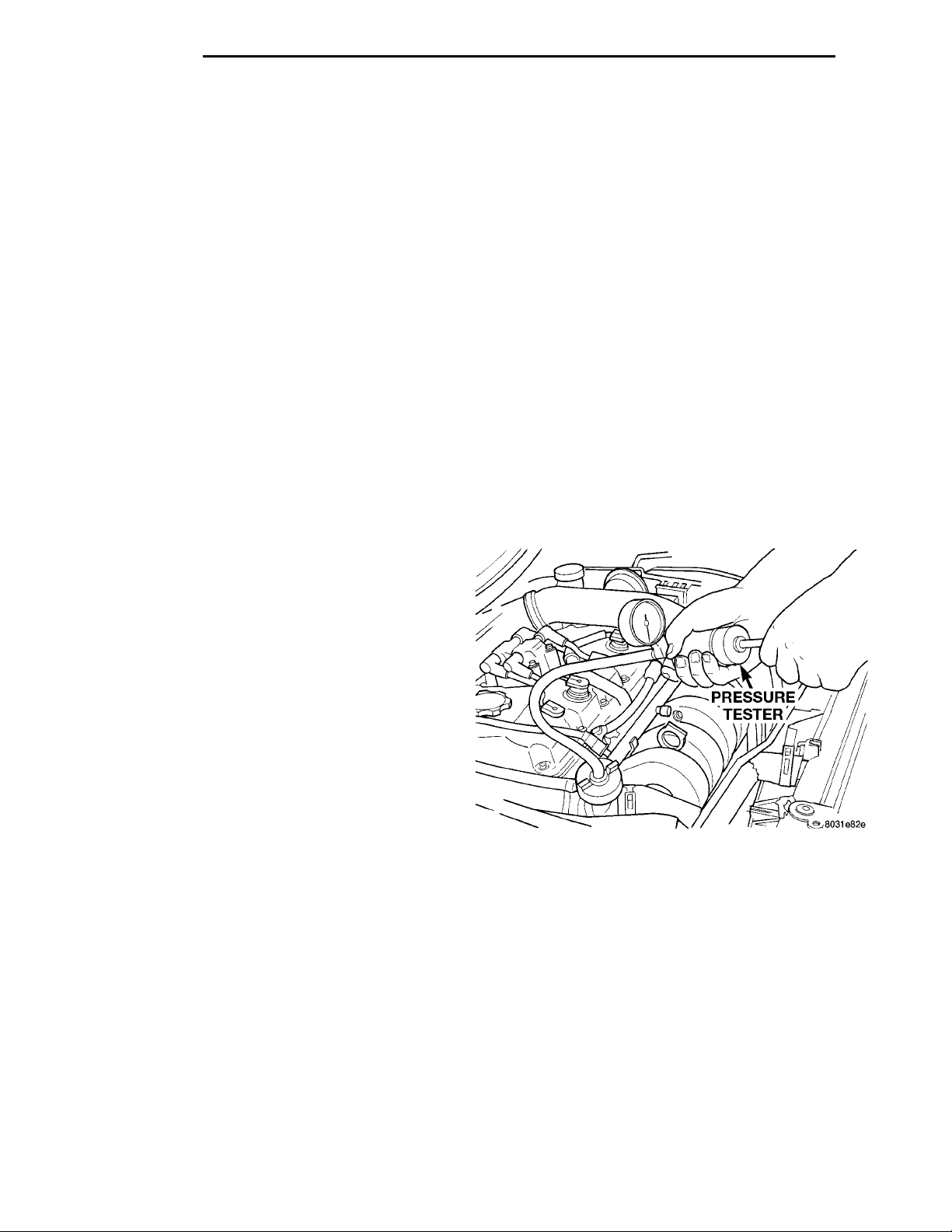
PRESSURETESTER
TESTING COOLING SYSTEM FOR LEAKS
The system should be full. With the engine not
running, wipe the filler neck sealing seat clean.
Attach a radiator pressure tester to the filler neck,
as shown in (Fig. 9) and apply 104 kPa (15 psi) pressure. If the pressure drops more than 2 psi in 2 minutes, inspect the system for external leaks.
Move all hoses at the radiator and heater while
system is pressurize at 15 psi, since some leaks occur
due to engine rock while driving.
WARNING: DO NOT REMOVE THE COOLING SYSTEM PRESSURE CAP WITH THE SYSTEM HOT AND
UNDER PRESSURE BECAUSE SERIOUS BURNS
FROM COOLANT CAN OCCUR.
(2) Remove pressure cap when engine is cold,
remove small amount of coolant Idle engine until
thermostat opens, you should observe coolant flow
while looking down the filler neck. Once flow is
detected install the pressure cap.
RADIATOR FAN CONTROL
Fan control is accomplished two ways. The fan
always runs when the air conditioning compressor
clutch is engaged. In addition to this control, the fan
is turned on by the temperature of the coolant which
is sensed by the coolant temperature sensor which
sends the message to the Powertrain Control Module
(PCM). The (PCM) turns on the fan through the
Pulse Width Module (PWM). See Wiring Diagrams
Manual for circuity and diagnostics provided.
Switching through the (PCM) provides fan control
for the following conditions.
• The fan will not run during cranking until the
engine starts no matter what the coolant temperature is.
• Fan will run when the air conditioning clutch is
engaged and low pressure cutout switch is closed.
• Fan will run at vehicle speeds above about 40
mph only if coolant temperature reaches 110°C
(230°F). It will turn off when the temperature drops
Fig. 9 Pressure Testing Cooling System—Typical
If there are no external leaks after the gauge dial
shows a drop in pressure, detach the tester. Start the
engine, and run the engine to normal operating temperature in order to open the thermostat and allow
the coolant to expand. Reattach the tester. If the needle on the dial fluctuates it indicates a combustion
leak, usually a head gasket leak.
WARNING: WITH THE PRESSURE TESTER IN
PLACE PRESSURE BUILDS UP QUICKLY. ANY
EXCESSIVE PRESSURE BUILD-UP DUE TO CONTINUOUS ENGINE OPERATION MUST BE
RELEASED TO A SAFE PRESSURE POINT. NEVER
PERMIT PRESSURE TO EXCEED 138 kPa (20 psi).
Page 15
PL COOLING 7 - 15
DIAGNOSIS AND TESTING (Continued)
If the needle on the dial does not fluctuate, race
the engine a few times. If an abnormal amount of
coolant or steam is emitted from the tail pipe, it may
indicate a faulty head gasket, cracked engine block,
or cracked cylinder head.
There may be internal leaks, which can be determined by removing the oil dipstick. If water globules
appear intermixed with the oil, it indicates an internal leak in the engine. If there is an internal leak,
the engine must be disassembled for repair.
PRESSURE CAP TO FILLER NECK SEAL PRESSURE RELIEF CHECK
The pressure cap upper gasket (seal) pressure
relief can be checked by removing the overflow hose
at the radiator filler neck nipple (Fig. 10). Attach the
radiator pressure tester to the filler neck nipple,
and pump air into the system. The pressure cap
upper gasket should relieve pressure at 69-124 kPa
(10-18 psi), and hold pressure at 55 kPa (8 psi) minimum.
WARNING: THE WARNING WORDS DO NOT OPEN
HOT ON THE PRESSURE CAP IS A SAFETY PRECAUTION. WHEN HOT, THE COOLING SYSTEM
BUILDS UP PRESSURE. TO PREVENT SCALDING
OR OTHER INJURY, THE PRESSURE CAP SHOULD
NOT BE REMOVED WHILE THE SYSTEM IS HOT
AND/OR UNDER PRESSURE.
There is no need to remove the pressure cap at any
time except for the following purposes:
• Check and adjust coolant freeze point
• Refill system with new coolant
• Conducting service procedures
• Checking for leaks
WARNING: IF VEHICLE HAS BEEN RUN
RECENTLY, WAIT 15 MINUTES BEFORE REMOVING
CAP. PLACE A SHOP TOWEL OVER THE CAP, AND
WITHOUT PUSHING DOWN, ROTATE IT COUNTERCLOCKWISE TO THE FIRST STOP. ALLOW FLUIDS
TO ESCAPE THROUGH THE OVERFLOW TUBE.
WHEN THE SYSTEM STOPS PUSHING COOLANT
AND STEAM INTO THE CRS TANK AND PRESSURE
DROPS, PUSH DOWN ON THE CAP AND REMOVE
IT COMPLETELY. SQUEEZING THE RADIATOR
INLET HOSE WITH A SHOP TOWEL (TO CHECK
PRESSURE) BEFORE AND AFTER TURNING TO
THE FIRST STOP IS RECOMMENDED.
PRESSURE TESTING COOLING SYSTEM PRESSURE CAP
Dip the pressure cap in water; clean off any deposits on the vent valve or its seat, and apply the cap to
end of radiator pressure tester (Fig. 11). Working the
Fig. 10 Cooling System Pressure Cap
plunger, increase the pressure to 104 kPa (15 psi) on
the gauge. If the pressure cap fails to hold pressure
of at least 97 kPa (14 psi), replace the cap.
CAUTION: The radiator pressure tester is very sensitive to small air leaks that will not cause cooling
system problems. A pressure cap that does not
have a history of coolant loss should not be
replaced just because it leaks slowly when tested
with this tool. Add water to the tool. Turn the tool
upside down, and recheck the pressure cap to confirm that the cap is faulty.
If the pressure cap tests properly while positioned the on radiator pressure tester, but will not
hold pressure or vacuum when positioned on the
filler neck, inspect the filler neck and cap top gasket for irregularities that may prevent the cap from
sealing properly.
LOW COOLANT LEVEL AERATION
• Will cause corrosion in the system.
• High reading shown on the temperature gauge.
• Air in the coolant will also cause loss of flow
through the heater.
• Exhaust gas leaks into the coolant can also
cause the above problems.
Page 16
ENGINE TOCOOLANT RECOV-ERY SYSTEM(CRS) HOSE COOLANTRECOVERYSYSTEM(CRS) TANKPRESSURE CAP
7 - 16 COOLING PL
DIAGNOSIS AND TESTING (Continued)
Fig. 11 Pressure Testing Radiator Cap
DEAERATION
Air can only be removed from the system by gathering under the pressure cap. On the next heat up it
will be pushed past the pressure cap into the CRS
tank by thermal expansion of the coolant. It then
escapes to the atmosphere in the CRS tank and is
replaced with solid coolant on cool down.
SERVICING COOLANT LEVEL
Fig. 12 Coolant Recovery System
TEMPERATURE GAUGE INDICATION
At idle the temperature gauge could rise slowly to
about 1/2 gauge travel. The fan will come on and the
gauge could drop to about 1/3 gauge travel, this is
normal.
SERVICE PROCEDURES
ROUTINE COOLANT LEVEL CHECK
NOTE: Do not remove radiator cap for routine coolant level inspections.
The coolant reserve system provides a quick visual
method for determining the coolant level without
removing the radiator cap. Simply observe, with the
engine idling and warmed up to normal operating
temperature, that the level of the coolant in the
reserve tank (Fig. 12) is between the add and full
marks.
ADDING ADDITIONAL COOLANT
NOTE: The radiator cap should not be removed.
When additional coolant is needed, it should be
added to the coolant reserve tank. Use only 50/50
concentration of ethylene glycol type antifreeze and
water
NOTE: The cooling system is closed and designed
to maintain coolant level to the top of the radiator.
When servicing requires a coolant level check in
the radiator, the engine must be off and not under
pressure. Drain several ounces of coolant from the
radiator drain cock while observing the Coolant
Recovery System (CRS) Tank. Coolant level in the
CRS tank should drop slightly. Then remove the radiator cap. The radiator should be full to the top. If
not, and the coolant level in the CRS tank is at the
ADD mark there is a air leak in the CRS system.
Check hose or hose connections to the CRS tank,
radiator filler neck or the pressure cap seal to the
radiator filler neck for leaks.
DRAINING COOLANT
NOTE: Drain, flush, and fill the cooling system at
the mileage or time intervals specified in the Maintenance Schedule in this Group. If the solution is
dirty or rusty or contains a considerable amount of
sediment, clean and flush with a reliable cooling
system cleaner. Care should be taken in disposing
of the used engine coolant from your vehicle.
Check governmental regulations for disposal of
used engine coolant.
Without removing radiator pressure cap and
with system not under pressure,
Page 17
DRAIN COCK VALVEDRAIN HOLE IN FASCIAPANEL
CYLINDER BLOCK PUMP BODY
PL COOLING 7 - 17
SERVICE PROCEDURES (Continued)
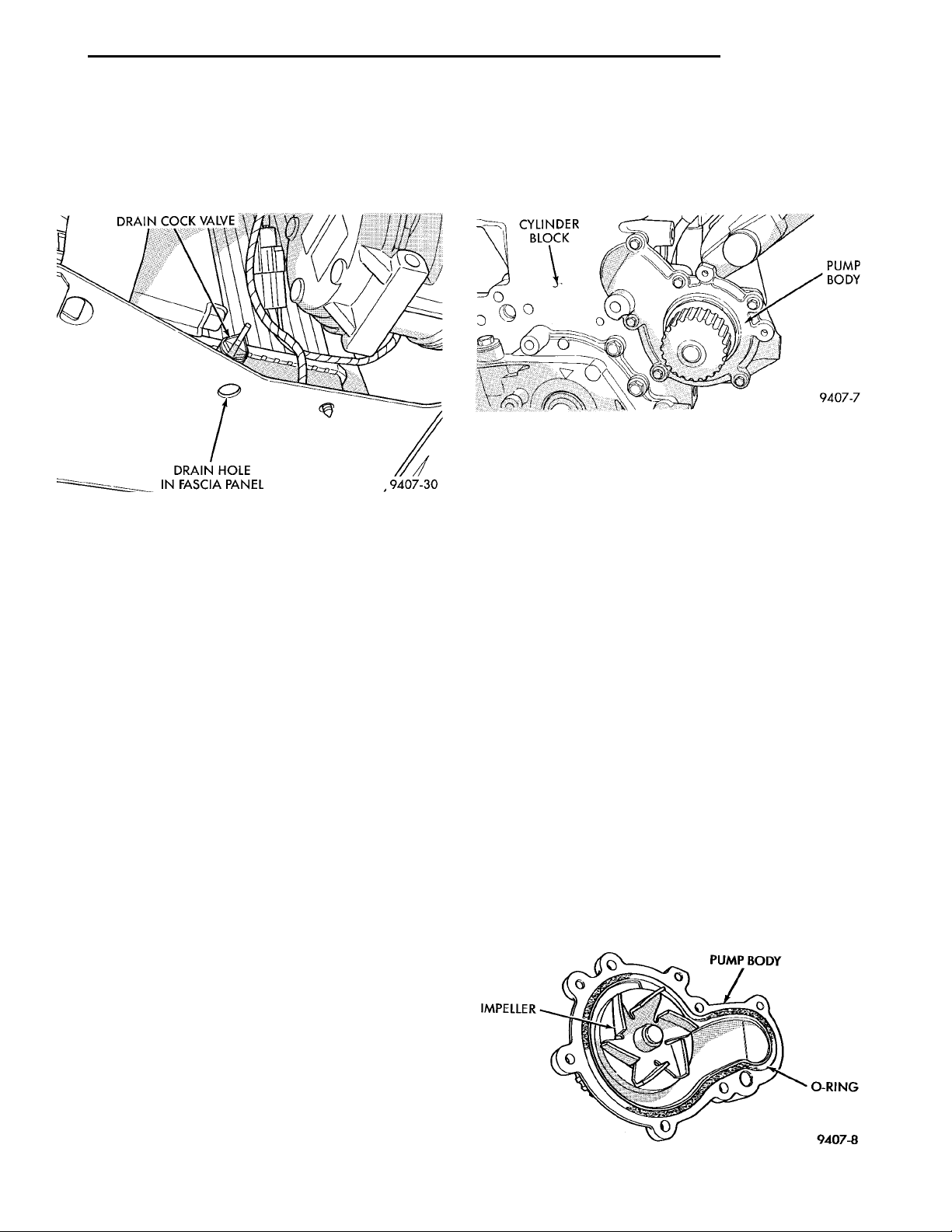
(1) Shut engine off and turn draincock counter-
clockwise to open (Fig. 13).
(2) The coolant reserve tank should empty first,
then remove the pressure cap. (if not, Refer to Testing Cooling System for leaks).
Fig. 13 Draining Cooling System
REFILLING COOLING SYSTEM
First clean system to remove old glycol, see Cooling
System Cleaning.
Fill system using antifreeze described in Coolant
section. Fill 50 percent of capacity with 100 percent
glycol. Then complete filling system with water.
Continue filling system until full, this provides better heater performance. Be careful not to spill
coolant on drive belts or the generator.
Fill coolant reserve system to at least the FULL
mark with 50/50 solution. It may be necessary to add
coolant to the reserve tank to maintain coolant level
between the FULL and ADD mark after three or four
warm-up, cool down cycles and trapped air has been
removed.
REMOVAL AND INSTALLATION
WATER PUMP
REMOVAL
(1) Raise vehicle on a hoist. Remove right inner
splash shield.
(2) Remove accessory drive belts and power steering pump. Refer to Accessory Drive Belt service of
this section.
(3) Drain cooling system. Refer to Draining Cooling System in this group.
(4) Support engine from the bottom and remove
right engine mount.
(5) Remove power steering pump bracket bolts and
set pump and bracket assembly aside. Power steering
lines do not need to be disconnected.
(6) Remove right engine mount bracket.
(7) Remove timing belt. Refer to Group 9, Engine
for procedure.
(8) Remove inner timing belt cover.
(9) Remove water pump attaching screws to engine
(Fig. 14).
Fig. 14 Water Pump
INSTALLATION
(1) Install new O-ring gasket in water pump body
O-ring groove (Fig. 15). Use small dabs of Mopar Silicone Rubber Adhesive Sealant around the water
pump body to secure O-ring in place during installation.
CAUTION: Make sure O-ring gasket is properly
seated in water pump groove before tightening
screws. An improperly located O-ring may cause
damage to the O-ring and cause a coolant leak.
(2) Assemble pump body to block and tighten
screws to 12 N·m (105 in. lbs.). Pressurize cooling
system to 15 psi with pressure tester and check
water pump shaft seal and O-ring for leaks.
(3) Rotate pump by hand to check for freedom of
movement.
(4) Install inner timing belt cover.
(5) Install timing belt. Refer to Group 9, Engine,
and Reassemble engine.
(6) Install right engine mount bracket and engine
mount. Refer to Group 9, Engine for procedure.
IMPELLER PUMP BODY O-RING
(7) Fill cooling system. See Filling Cooling System.
(8) Install power steering pump and accessory
drive belts, Refer to Accessory Drive Belts, in this
Group.
Fig. 15 Water Pump Body
Page 18
7 - 18 COOLING PL
REMOVAL AND INSTALLATION (Continued)
WATER PUMP INLET TUBE
The inlet tube connects the water pump to the
radiator and heater core. This tube is sealed by a
O-ring and held in place by fasteners to the block.
REMOVAL
CAUTION: Do not use any sharp tools to remove
hoses from inlet tube. This may cause the tube to
leak.
(1) Drain cooling system. Refer to procedure outlined in this section.
(2) Remove upper radiator hose to access the hose
connections at the inlet tube.
(3) Remove lower radiator hose and heater hose
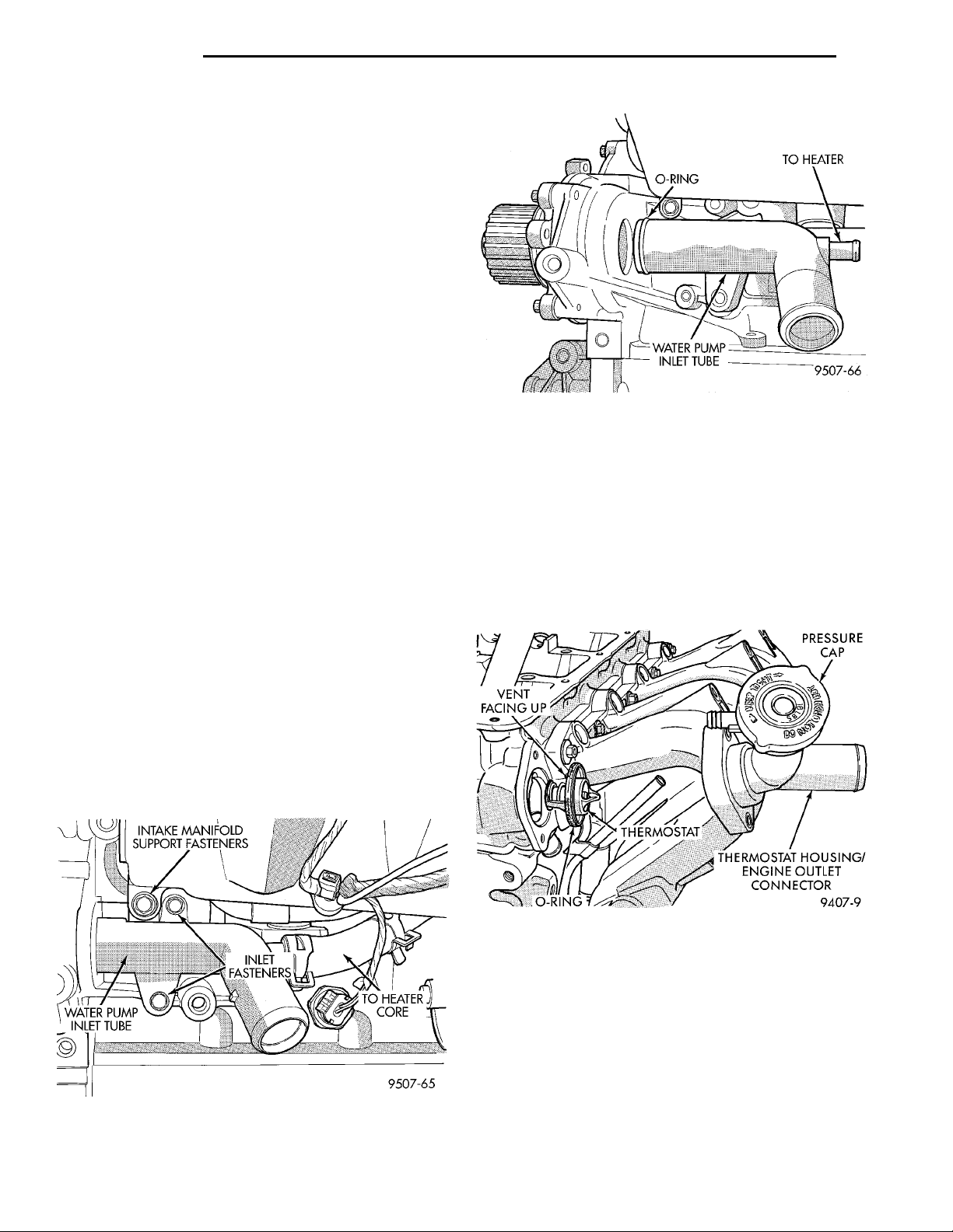
from the inlet tube (Fig. 16).
(4) Remove the two fasteners that hold the inlet
tube to the block and one fastener that holds the
intake manifold to inlet tube.
(5) Rotate tube while removing the tube from the
engine block (Fig. 17).
INSTALLATION
(1) Inspect the O-ring for damage before installing
the tube into the cylinder block (Fig. 17).
(2) Lube O-ring with coolant and install into the
cylinder block opening.
(3) Install two fasteners to the engine block and
the one fastener to the intake manifold. Tighten fasteners to 12 N·m (105 in. lbs.).
(4) Connect lower radiator hose and heater hose to
inlet tube.
(5) Install upper radiator hose.
WATER PUMP INLET
(6) Fill cooling system. Refer to procedure outlined
INTAKE MANIFOLD SUPPORTFASTENERS
TUBE
TO HEATER
CORE
INLET FAS-TENERS
in this section.
(7) Pressure system to 104 kPa (15 psi) to check
for leaks.
ENGINE THERMOSTAT
REMOVAL
(1) Drain cooling system to the thermostat level or
below.
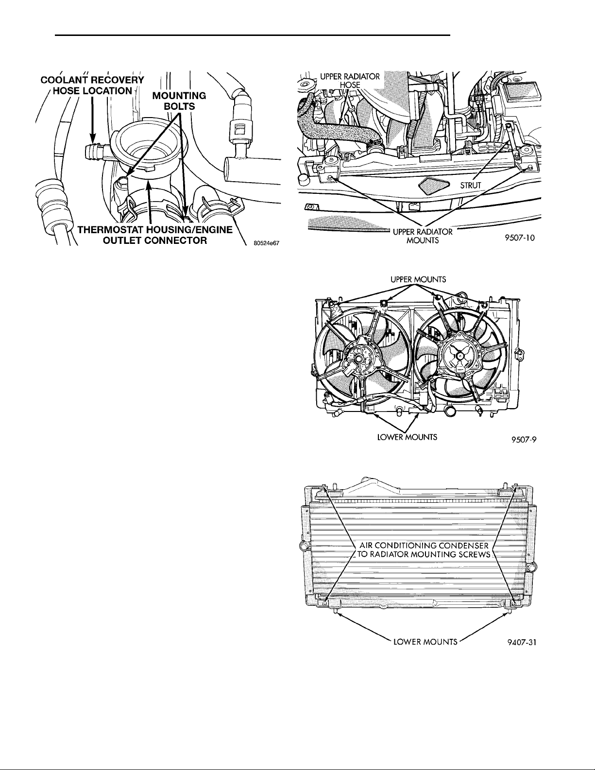
(2) Remove coolant recovery system (CRS) hose
and thermostat/engine outlet connector bolts (Fig. 18)
or (Fig. 19).
(3) Remove thermostat an O-ring assembly, and
clean sealing surfaces.
Fig. 17 Water Pump Inlet Tube
Fig. 16 Water Pump Inlet Tube Hose Connections
Fig. 18 Thermostat/Engine Outlet Connector—SOHC
INSTALLATION
(1) Place the new thermostat assembly into the
thermostat housing/outlet connector. Align vent with
notch in cylinder head.
(2) Install thermostat housing/outlet connector
onto cylinder head and tighten bolts to 12.5 N·m (110
in. lbs.). Connect the coolant recovery system (CRS)
hose.
(3) Refill cooling system (see Refilling System ).
Page 19
COOLANT RECOVERY HOSELOCATION MOUNTING BOLTSTHERMOSTAT HOUSING/EN-GINE OUTLET CONNECTOR
PL COOLING 7 - 19
REMOVAL AND INSTALLATION (Continued)
Fig. 19 Thermostat/Engine Outlet Connector—DOHC
RADIATOR
REMOVAL
WARNING: DO NOT REMOVE THE CYLINDER
BLOCK PLUG OR THE RADIATOR DRAINCOCK
WITH THE SYSTEM HOT AND UNDER PRESSURE
BECAUSE SERIOUS BURNS FROM COOLANT CAN
OCCUR.
(1) Disconnect negative battery cable from battery.
(2) Drain cooling system. Refer to Draining Cool-
ing System of this section.
(3) Remove hose clamps and hoses from the radia-
tor.
(4) Disconnect automatic transmission hoses and
plug off, if equipped.
(5) Remove radiator to battery strut (Fig. 20).
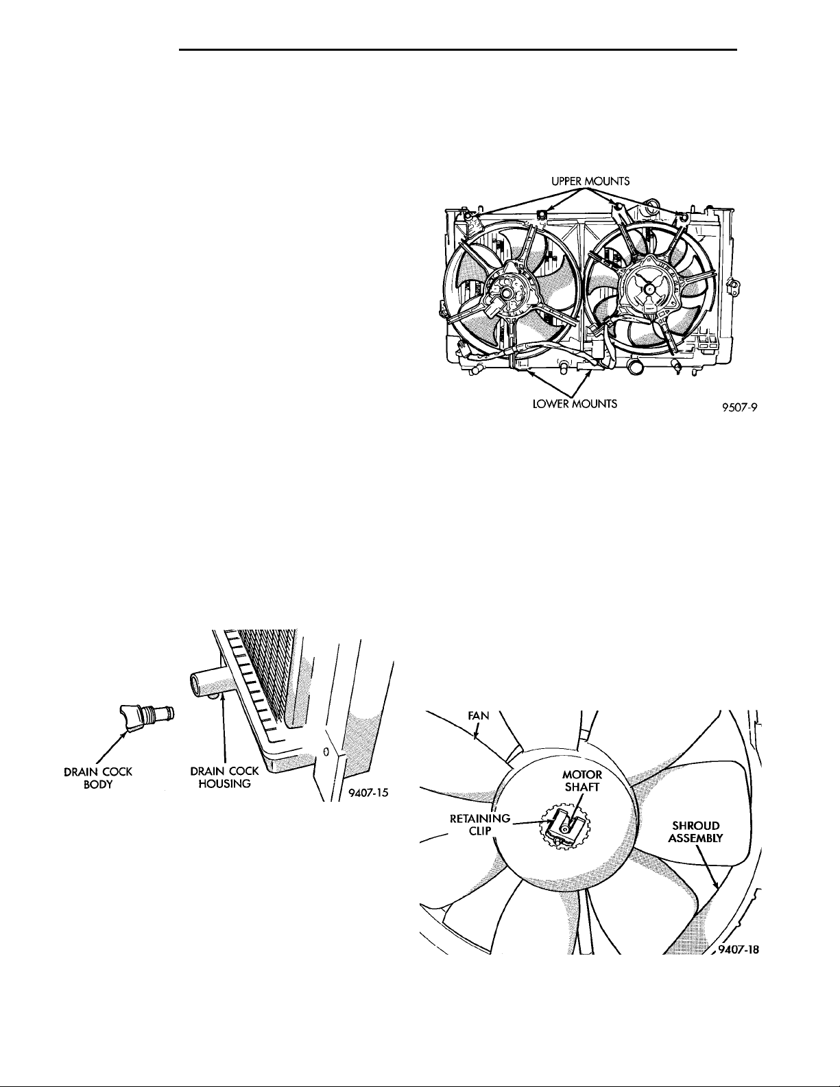
Remove fan module assembly by disconnecting fan
motor electrical connector. Remove fan shroud retaining screws, located on the top of the shroud (Fig. 21).
Lift shroud up and out of bottom shroud attachment
clips separating shroud from radiator. For dual fan
applications the left fan module may be removed
first, then the right side module last. Fan damage
should always be avoided.
(6) Remove upper radiator isolator bracket mounting screws. Disconnect the engine block heater wire
if equipped.
(7) Remove the air conditioning condenser attaching screws located at the front of the radiator, if
equipped (Fig. 22). Lean condenser forward, it is not
necessary to discharge the air conditioning system to
remove radiator.
(8) Radiator can now be lifted free from engine
compartment. Care should be taken not to dam-
age radiator cooling fins or water tubes during
removal.
Fig. 20 Radiator Mounting
AIR CONDITIONING CONDENSER TO RADIA-TOR MOUNTING SCREWSLOWERMOUNTS
Fig. 21 Servicing Fan Module
Fig. 22 A/C Condenser to Radiator Mounting Screws
INSTALLATION
(1) Slide radiator down into position behind radia-
tor support (yoke).
(2) Attach air conditioning condenser to radiator if
equipped (Fig. 22), with four mounting screws and
Page 20
7 - 20 COOLING PL
REMOVAL AND INSTALLATION (Continued)
tighten to 5.4 N·m (50 in. lbs.). Then seat the assembly lower rubber isolators into the mounting holes
provided in the lower crossmember.
(3) Tighten radiator isolator mounting bracket
screws to 7.4 N·m (65 in. lbs.). The radiator should
have clearance to move up approximately 5 to 8 mm
(0.25 in.) after assembled.
(4) Connect automatic transmission hoses, if
equipped. Tighten hose clamps to 4 N·m (35 in. lbs.).
(5) Slide fan module down into clip(s) on lower
radiator flange (Fig. 21). For dual fan application
install the right fan module first and then the left
fan module. Install retaining screws and tighten to
5.4 N·m (50 in. lbs.).
(6) Install radiator hoses and coolant reserve hose
align hoses and position hose clamps so they will not
interfere with the engine or hood.
(7) Connect fan motor electrical connection and
connect negative battery cable.
(8) Fill cooling system with coolant. Refer to
Refilling Cooling Systems. in this group.
(9) Operate engine until it reaches normal operating temperature. Check cooling system and automatic transmission for correct fluid levels.
RADIATOR DRAINCOCK
REMOVAL
(1) Turn the drain cock stem counterclockwise to
unscrew the stem. When the stem is unscrewed to
the end of the threads, pull the stem (Fig. 23) from
the radiator tank.
REMOVAL FAN MODULE
(1) Disconnect fan motor leads from module.
(2) Remove fan module fasteners from radiator
(Fig. 24).
Fig. 24 Servicing Fan Module
FAN BLADE
There are no repairs to be made to the fan. If the
fan is warped, cracked, or otherwise damaged, it
must be replaced with only the recommended part
for adequate strength, performance and safety.
(1) To remove fan from motor shaft, bench support
the motor and motor shaft, while removing the fan
retaining clip, so that the shaft and motor will not be
damaged by excessive force. Surface burr removal
may be required to remove fan from motor
RETAINING CLIP MOTOR SHAFT SHROUD ASSEM-BLY
shaft (Fig. 25). Do not permit the fan blades to
FAN
touch the bench.
(2) To install fan on motor shaft, slide the fan over
shaft. Support motor and shaft as above while
installing fan retaining clip.
Fig. 23 Draincock
INSTALLATION
(1) Push the draincock assembly body into the
tank opening.
(2) Tighten the draincock stem by turning clock-
wise to 2.0-2.7 N·m (18-25 in. lbs.).
RADIATOR FANS AND MOTOR
All models use a single speed electric motor driven
cooling system fans. The fan modules includes a
motor, fan blade, and support shroud. The module is
fastened to the radiator by screws.
Fig. 25 Servicing Radiator Fan
Page 21
PIVOT BOLT
BOLT BOLTP/S PIVOT BRACKETSQUARE OPENING ADJUST
PL COOLING 7 - 21
REMOVAL AND INSTALLATION (Continued)
INSTALLATION FAN MODULE
(1) Install module to radiator. Torque shroud to
radiator fasteners to 7.5 N·m (65 in. lbs.).
(2) Connect fan motor lead. For wiring diagrams
of fan motor systems Refer to 8W Wiring Diagrams .
ELECTRIC FAN MOTOR—SERVICE
WARNING: Do not disassemble the fan motor from
the support bracket.
Electric fan motor is serviced as an assembly with
the fan module.
FAN SHROUD
Some fan shrouds are equipped with flapped doors
to prevent the shroud from restricting air flow at
high speeds.
All vehicles have fan shrouds to improve fan air
flow efficiency.
The shroud supports the electric fan motor and
fan. For removal and installation procedures, refer to
radiator removal in this Section.
ENGINE BLOCK HEATER
REMOVAL
(1) Drain coolant from radiator and cylinder block.
Refer to Cooling System Drain, Clean, Flush and
Refill of this section for procedure.
(2) Detach power cord plug from heater.
(3) Loosen screw in center of heater. Remove
heater assembly.
INSTALLATION
(1) Thoroughly clean core hole and heater seat.
(2) Insert heater assembly with element loop positioned upward.
(3) With heater seated, tighten center screw
securely to assure a positive seal.
(4) Fill cooling system with coolant to the proper
level, vent air, and inspect for leaks. Pressurize system with Radiator Pressure Tool before looking for
leaks.
ACCESSORY DRIVE BELTS
AIR CONDITIONING COMPRESSOR AND POWER STEERING PUMP
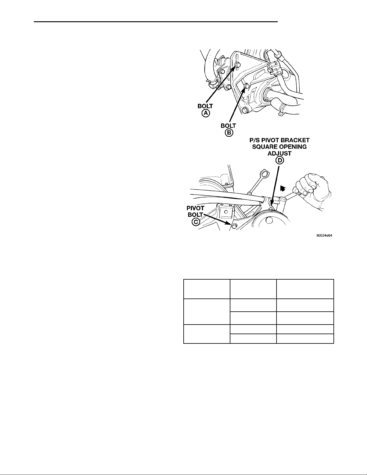
(1) Loosen the power steering pump locking bolts
A and B and pivot bolt C (Fig. 26) to remove and
install belt and/or adjust belt tension.
(2) Using a 1/2” breaker bar, adjust belt tension by
applying torque to the square D hole on the power
steering pivot bracket. Adjust tension to specification
given in Belt Tension Chart.
Fig. 26 Power Steering Pump Adjustment
(3) Tighten in order, first tighten locking bolt A to
27 N·m (20 ft. lbs.) then, bolt B to 27 N·m (20 ft. lbs.)
Then pivot bolt C to 54 N·m (40 ft. lbs.).
Accessory
Drive Belt
Power Steering
Pump and Air
Conditioning
Compressor
Generator New 135 lb. 121 N·m (90 ft. lbs.)
Gauge Torque
New 135 lb. 121 N·m (90 ft. lbs.)
Used 100 lb. 81 N·m (60 ft. lbs.)
Used 100 lb. 81 N·m (60 ft. lbs.)
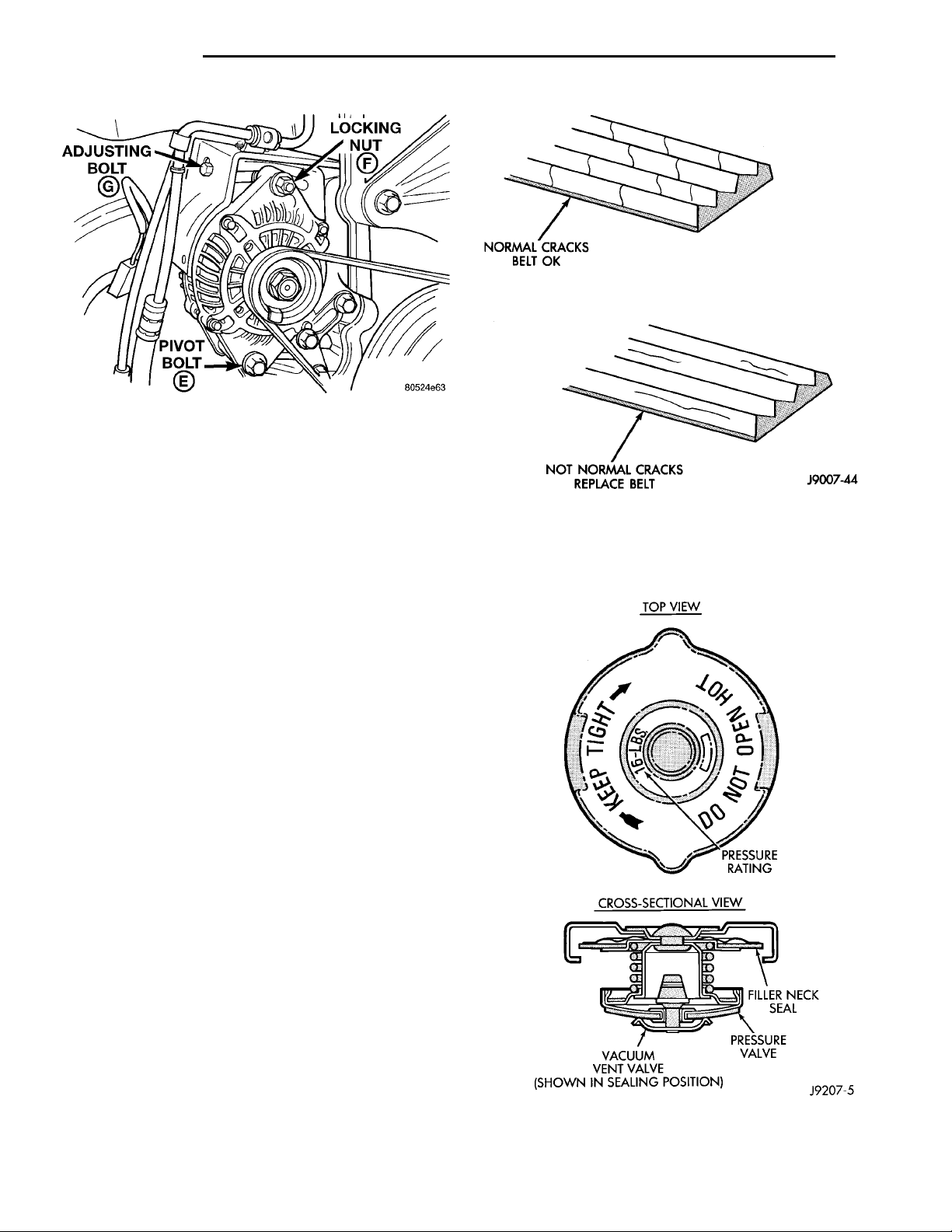
GENERATOR BELT
(1) Loosen pivot bolt E then locking nut F and
adjusting bolt G (Fig. 27) to remove and install belt
and/or adjust belt tension.
(2) Tighten adjusting bolt G, adjust belt tension to
specification shown in Belt Tension Chart.
(3) Tighten pivot bolt E to 54 N·m (40 ft. lbs.).
Locking nut F to 54 N·m (40 ft. lbs.).
Page 22
NORMAL CRACKSBELT OKNOT NORMAL CRACKSRELACE BELT
7 - 22 COOLING PL
Fig. 27 Generator Adjustment
CLEANING AND INSPECTION
WATER PUMP
Replace water pump body assembly if it has any of
these defects:
(1) Cracks or damage on the body.
(2) Coolant leaks from the shaft seal, evident by
coolant traces on the pump body.
(3) Loose or rough turning bearing.
(4) Impeller rubs either the pump body or the
engine block.
(5) Impeller loose or damaged.
(6) Sprocket or sprocket flange loose or damaged.
ACCESSORY DRIVE BELT INSPECTION
Belt replacement under any or all of the following
conditions is required, excessive wear, frayed cords or
severe glazing.
Poly-V-Belt system with back drive pulley may
develop minor cracks across the ribbed side (due to
reverse bending). These minor cracks are considered
normal and acceptable. Cracks parallel are not (Fig.
28).
NOTE: Do not use any type of belt dressing or
restorer on Poly-V-Belt and V-Belt
TOP VIEWPRESSURE RATINGCROSS-SECTIONAL VIEW FILLER NECK SEALPRESSURE VALVEVACUUM VENT VALVE (SHOWN IN SEAL-ING POSITION)
Fig. 28 Drive Belt Wear Pattern
A replacement cap must be of the type designed for
coolant reserve systems. This design ensures system
pressurization.
COOLING SYSTEM CAP
Hold the cap in your hand, right side up (Fig. 29).
The vent valve at the bottom of the cap should open
with a slight pull. If the rubber gasket has swollen,
preventing the valve from opening, replace the cap.
If any light can be seen between vent valve and
the rubber gasket, replace the cap. Use only a
replacement cap that has a spring to hold the
vent shut.
Fig. 29 Cooling System Pressure Cap
Page 23
PL COOLING 7 - 23
CLEANING AND INSPECTION (Continued)
CLEANING COOLING SYSTEM
Drain cooling system (see: Draining Cooling System ) and refill with clean water (see: Refilling
Cooling System ). Run engine with radiator cap
installed until upper radiator hose is hot. Stop
engine and drain water from system. If water is
dirty, fill, run and drain system again until water
runs clear.
RADIATOR FLUSHING
Drain cooling system and remove radiator hoses
from engine. Install suitable flushing gun in radiator
lower hose. Fill radiator with clean water and turn
on air in short blasts.
CAUTION: Internal radiator pressure must not
exceed 138 kPa (20 psi) as damage to radiator may
result. Continue this procedure until water runs
clear.
ENGINE FLUSHING
Drain radiator (see: Draining Cooling System )
and remove hoses from radiator. Remove engine thermostat and reinstall thermostat housing. A gasket
may be needed to seal the housing to cylinder head
because the seal is part of thermostat. Install suitable flushing gun to thermostat housing hose. Turn
on water, and when engine is filled, turn on air, but
no higher than 138 kPa (20 psi) in short blasts. Allow
engine to fill between blasts of air. Continue this procedure until water runs clean. Install thermostat and
fill cooling system. Refer to Refilling Cooling Sys-
tem ) for procedure.
REVERSE FLUSHING
Reverse flushing of the cooling system is the forcing of water through the cooling system, using air
pressure in a direction opposite to that of the normal
flow of water. This is only necessary with dirty systems and evidence of partial plugging.
ADJUSTMENTS
PROPER BELT TENSION
Satisfactory performance of the belt driven accessories depends on belt condition and proper belt tension. Refer to Accessory Drive Belt Inspection in this
section. There are two belt tensioning methods given
in order of preference:
• Belt tension gauge method.
• Torque equivalent method.
The belt tension gauge method usually requires the
vehicle to be raised on a hoist and the splash shield
removed.
TORQUE EQUIVALENT METHOD
Adjustable accessory brackets provided with a 13
mm (1/2 in.) square hole for a torque wrench can use
an equivalent torque value for belt adjustment.
Equivalent torque values for adjusting these accessory drive belts are specified in the Belt Tension
Chart.
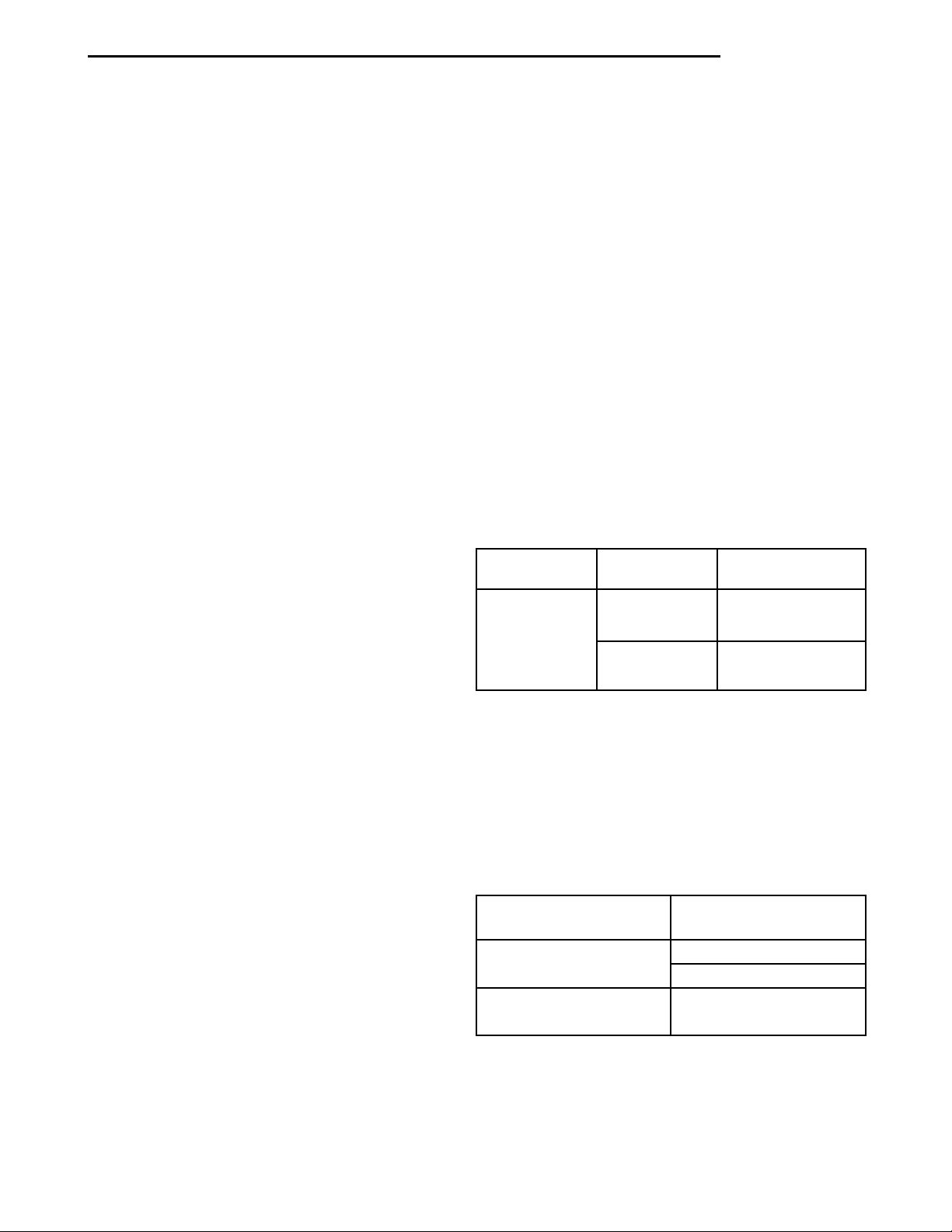
BELT TENSION CHART
ACCESSORY
DRIVE BELT
Power Steering
Pump and A/C
Compressor
Generator New 135 lb. 121 N·m (90 ft. lbs.)
GAUGE TORQUE
New 135 lb. 121 N·m (90 ft. lbs.)
Used 100 lb. 81 N·m 60 ft. lbs.)
Used 100 lb. 81 N·m 60 ft. lbs.)
BELT TENSION GAUGE METHOD
NOTE: Use belt tensioning Special Tool Kit C-4162
for:
• For conventional belts and Poly-V-belts.
Adjust the belt tension for a New or Used belt as
prescribed in the Belt Tension Chart Gauge.
BELT TENSION CHART GAUGE
CHEMICAL CLEANING
One type of corrosion encountered with aluminum
cylinder heads is aluminum hydroxide deposits. Corrosion products are carried to the radiator and deposited when cooled off. They appear as dark grey when
wet and white when dry. This corrosion can be
removed with a two part cleaner (oxalic acid and
neutralizer) available in auto parts outlets. Follow
manufacturers directions for use.
ACCESSORY DRIVE
BELT
Power Steering Pump
and A/C Compressor
Generator New 135 lb.
GAUGE
New 135 lb.
Used 100 lb.
Used 100 lb.
Page 24
7 - 24 COOLING PL
SPECIFICATIONS
COOLING SYSTEM CAPACITY
7.00 LITERS 7.40 QTS.
CAPACITY, Includes Heater and Coolant Reserve
System
TORQUE
DESCRIPTION TORQUE
A/C Condenser to Radiator ....7.2N·m(65in.lbs.)
Fan Module to Radiator ......7.2N·m(65in.lbs.)
Fan Motor to Shroud
Retaining Screws (A/C equipped) .......3.8N·m
(34 in. lbs.)
Fan Motor to Shroud
Retaining Screws (Non A/C equipped) . . . 2.3 N·m
(20 in. lbs.)
Radiator (Cooling Module)
to Body Screws ...........7.2N·m(65in.lbs.)
Thermostat Housing/Engine
Outlet Connector Screws . . . 12 N·m (105 in. lbs.)
Upper Radiator Crossmember
Bolts ..................28N·m(250 in. lbs.)
Water Pump to Engine Block
Mounting Bolts ..........12N·m(105 in. lbs.)
Water Pump Inlet Tube to
Engine Block Mounting
Screws .................12N·m(105 in. lbs.)
SPECIAL TOOLS
COOLING
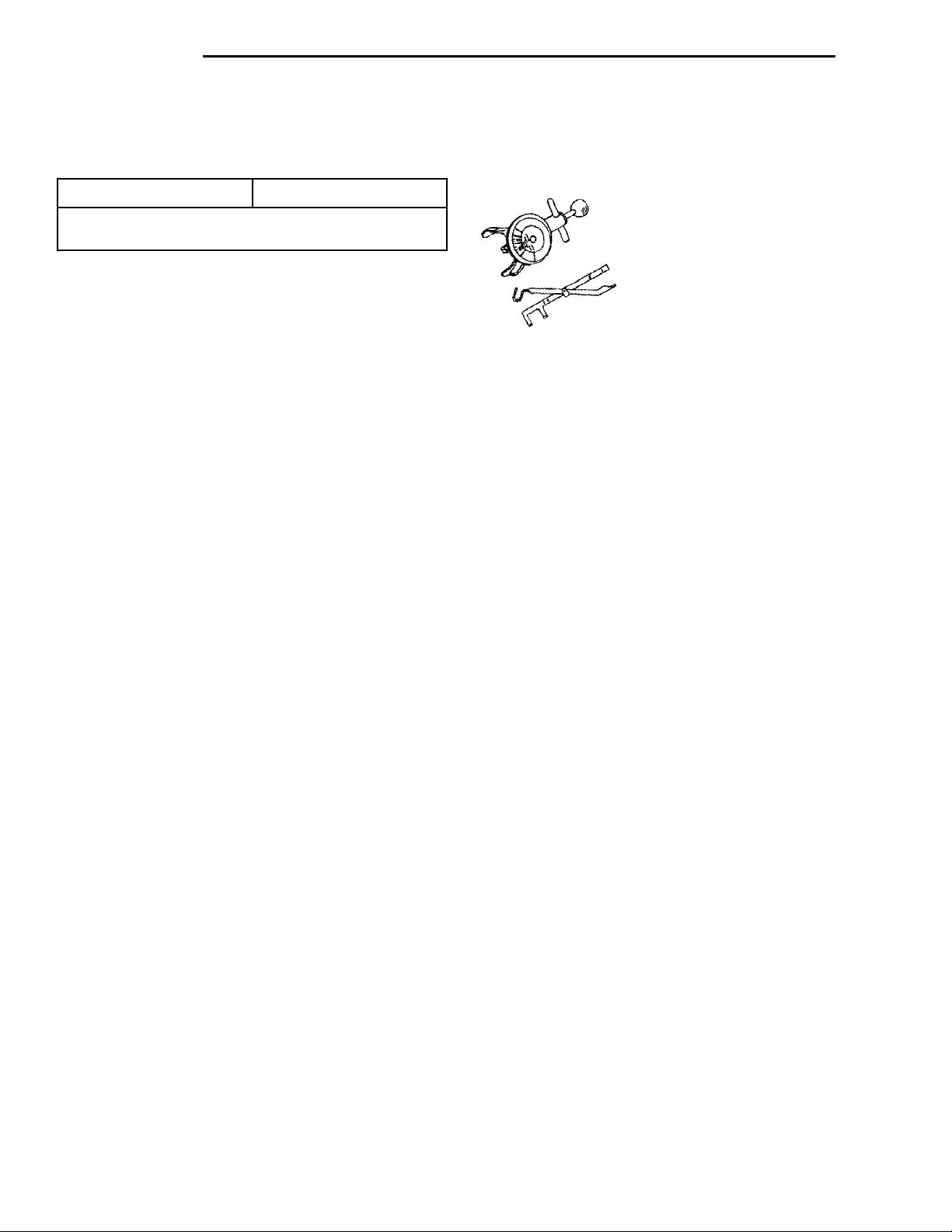
Accessory Drive Belt Tension Gauge C-4162
 Loading...