

Page 1

PL CLUTCH 6 - 1
CLUTCH
CONTENTS
page page
GENERAL INFORMATION
CLUTCH COMPONENTS .................. 1
CLUTCH DISC AND COVER APPLICATION .... 2
CLUTCH REPLACEMENT ................. 2
DESCRIPTION AND OPERATION
CLUTCH CABLE ........................ 2
CLUTCH PEDAL POSITION SWITCH ......... 2
DIAGNOSIS AND TESTING
CLASH–INTO–REVERSE COMPLAINTS ...... 7
CLUTCH CHATTER COMPLAINTS ........... 7
CLUTCH COVER AND DISC RUNOUT ........ 7
CLUTCH DIAGNOSIS ..................... 4
CLUTCH PEDAL POSITION SWITCH ......... 2
DRIVE PLATE MISALIGNMENT ............. 7
REMOVAL AND INSTALLATION
CLUTCH ASSEMBLY ..................... 9
GENERAL INFORMATION
CLUTCH COMPONENTS
NOTE: Neon vehicles produced at the Toluca
assembly plant, in Mexico, have conventional clutch
and flywheel assemblies. Vehicles produced at Belvidere assembly plant have modular clutch assemblies.
Before beginning clutch service, check the 11th
character of the V.I.N. to determine where it was
produced. The 11th character is “D” for vehicles
produced at Belvidere, or “T” for vehicles produced
at Toluca.
For a vehicle produced at Belvidere assembly,
refer to this manual for service information on the
modular clutch assembly. For a vehicle produced at
Toluca assembly, refer to the following information
to determine proper service procedures.
Service parts stock only a Conventional Clutch
Disc Assembly or a Modular Clutch Service Package to service Toluca built vehicles. The Modular
Clutch Service Package contains the following
parts:
• One modular clutch assembly
• One drive plate assembly
• One backing plate assembly
• Four drive plate to clutch bolts
• Eight drive plate to crankshaft bolts
If only the clutch disc requires replacement,
obtain the clutch disc. Replace the clutch disc
CLUTCH CABLE ........................ 7
CLUTCH PEDAL POSITION SWITCH ......... 8
RELEASE BEARING AND FORK ........... 10
CLEANING AND INSPECTION
CLEANING PRECAUTIONS ............... 11
CLUTCH CONTAMINATION ............... 11
ADJUSTMENTS
CLUTCH CABLE ........................ 11
CLUTCH PEDAL POSITION SWITCH ........ 12
SPECIFICATIONS
TORQUE ............................. 12
SPECIAL TOOLS
CLUTCH ............................. 12
using the information in the Removal And Installation section of this manual.
If the clutch pressure plate or flywheel requires
replacement, obtain the Modular Clutch Service
Package. Refer to this manual for service information on the modular clutch assembly.
The clutch assembly used in this vehicle consists of
a single, dry-type clutch disc and a diaphragm style
clutch cover.
The clutch disc has cushion springs riveted to the
disc hub assembly. The clutch disc facings are riveted
to the cushion springs. The facings are made from a
non-asbestos material.
The clutch cover pressure plate assembly is a diaphragm type unit with a one-piece diaphragm spring
with multiple release fingers. The pressure plate
release fingers are preset during manufacture and
are not adjustable.
A sleeve-type release bearing is used to engage and
disengage the clutch cover pressure plate. The bearing is prelubed during manufacture and is a sealed
unit.
The release bearing is operated by a pivoting
release fork in the clutch housing. The fork pivots on
a ball stud within the housing. The release fork is
actuated by a self-adjusting clutch cable.
The clutch cable has a unique self-adjuster mechanism built into the cable which compensates for
clutch disc wear. The cable requires no maintenance
or lubrication. There are no serviceable components
on the cable assembly.
Page 2
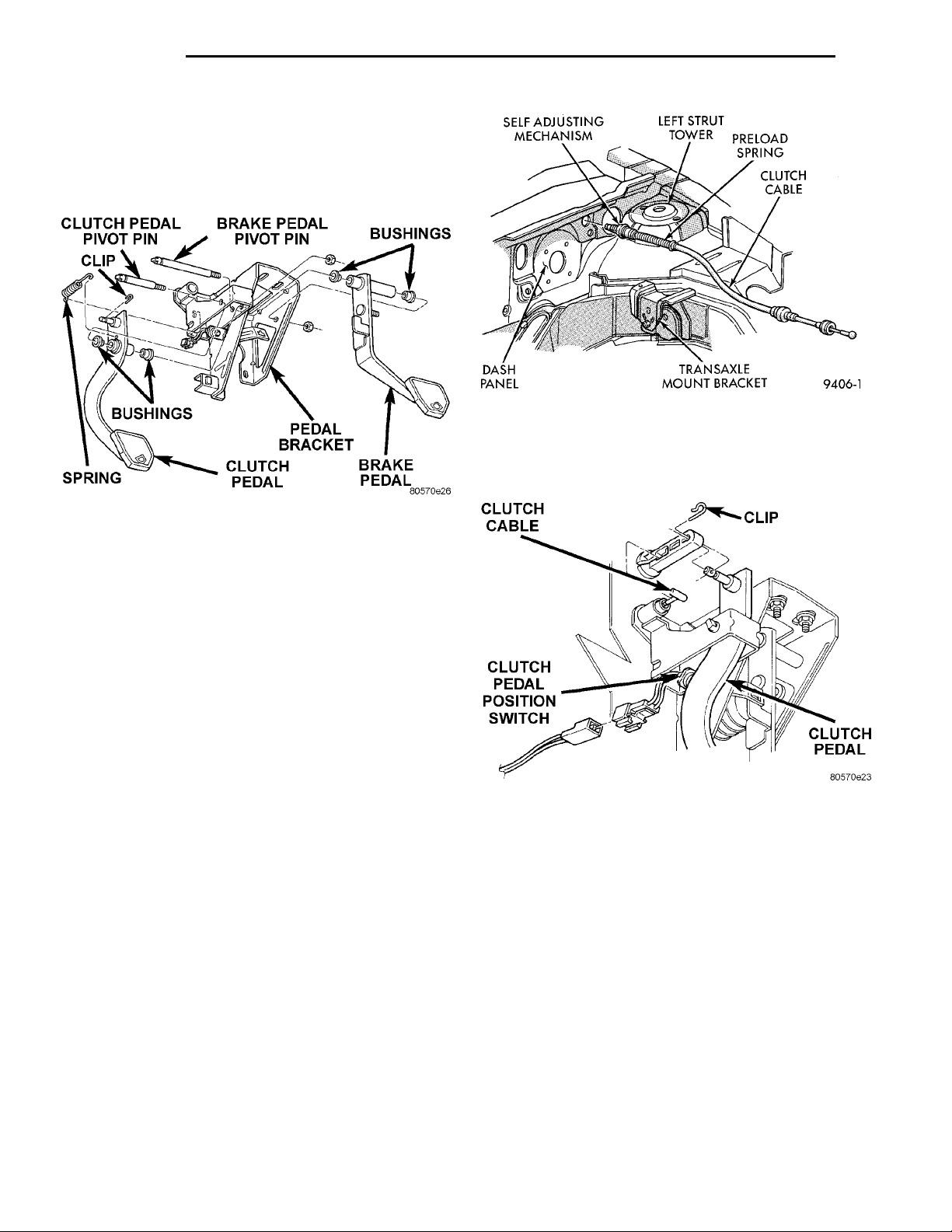
CLIPCLUTCH PEDAL PIVOT PIN BRAKE PEDAL PIVOT PIN BUSHINGSBRAKE PEDALPEDAL BRACKETCLUTCH PEDALBUSHINGSSPRING
DASH PANELSELF ADJUSTING MECHA-NISM LEFT STRUT TOWER PRELOAD SPRINGCLUTCH CABLETRANSAXLE MOUNTBRACKET
CLUTCH CABLE CLIP CLUTCH PEDALCLUTCHPEDAL POSI-TION SWITCH
6 - 2 CLUTCH PL
GENERAL INFORMATION (Continued)
The clutch pedal is connected to the cable through
a plastic spacer. The upper end of the clutch pedal
pivots in the pedal bracket on two nylon bushings
and a shaft (Fig. 1). These bushings are greased at
assembly and do not require periodic lubrication.
Fig. 2 Clutch Cable Routing
The clutch pedal position switch IS NOT adjustable. The pedal blade contacts the switch in the down
position (Fig. 3).
Fig. 1 Clutch Pedal Components
CLUTCH DISC AND COVER APPLICATION
The 2.0 single overhead cam engine uses a 216 mm
(8.5 in.) clutch disc. The manual transaxle is available only with the 2.0 liter engine.
CLUTCH REPLACEMENT
The transaxle must be removed to service the
clutch disc, pressure plate, flywheel/drive plate,
and/or clutch release bearing and lever.
DESCRIPTION AND OPERATION
CLUTCH CABLE
The manual transaxle clutch release system has a
unique self-adjusting mechanism to compensate for
clutch disc wear (Fig. 2). This adjuster mechanism is
located within the clutch cable assembly. The preload
spring maintains tension on the cable. This tension
keeps the clutch release bearing continuously loaded
against the fingers of the clutch cover assembly.
CLUTCH PEDAL POSITION SWITCH
The clutch pedal position switch functions as a
safety interlock device. It prevents possible engine
cranking with the clutch engaged.
The clutch pedal position switch is wired in series
between the starter relay coil and the ignition
switch.
The clutch pedal position switch is mounted to a
bracket located behind the clutch pedal. The switch
is held in place by four plastic wing tabs.
Fig. 3 Clutch Pedal Position Switch and
Components
DIAGNOSIS AND TESTING
CLUTCH PEDAL POSITION SWITCH
CLUTCH PEDAL POSITION SWITCH–ELECTRICAL TEST
Disconnect clutch pedal position switch harness
from instrument panel wiring harness. Using an
ohmmeter, check for continuity between the two terminals in the connector on the switch harness. There
should be no continuity between the terminals when
the switch is in its normal (fully extended) position.
When the switch is depressed more than 1.25 mm
(0.050), the ohmmeter should show continuity (zero
ohms).
If ohmmeter readings do not fall within these
ranges, the switch is defective, and must be replaced.
Page 3
PL CLUTCH 6 - 3
DIAGNOSIS AND TESTING (Continued)
CLUTCH PEDAL POSITION SWITCH–MECHANICAL TEST
With the park brake set and the vehicle IN NEU-
TRAL, turn the key to the start position. The vehicle
should not crank. If the vehicle cranks, the switch is
defective (shorted out) and must be replaced. If the
vehicle does not crank, proceed to the next step.
WARNING: BEFORE PERFORMING THIS STEP, BE
SURE THAT THE AREA IN FRONT OF THE VEHICLE
IS CLEAR OF OBSTRUCTIONS AND PEOPLE. VEHICLE MAY MOVE WHEN PERFORMING THIS TEST.
With the park brake set and the vehicle IN GEAR,
turn the key to the start position and hold it there.
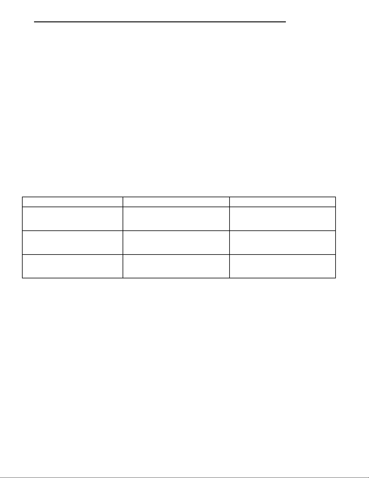
SERVICE DIAGNOSIS–CLUTCH PEDAL POSITION SWITCH
CONDITION POSSIBLE CAUSES CORRECTION
ENGINE WON’T CRANK WHEN
CLUTCH PEDAL IS PRESSED TO
THE FLOOR
Switch does not have continuity
when plunger is depressed 1.25 mm
Switch plunger is not depressed
when clutch pedal is pushed to the
floor
Problem is related to other
components in the starting circuit
Slowly depress the clutch pedal and feel for any
vehicle motion when the starter is energized. If there
is no motion, the switch is working properly.
If motion is felt, check to see if the switch is making contact when the pedal is between 25 mm (1.0
in.) and 6 mm (0.25 in.) from the floor. If this condition is met, then the problem is either the clutch or
the self-adjusting cable (See “Clutch Will Not Disengage Properly”). If this condition is not met, then the
switch mounting tab on the brake bracket is bent,
and the brake bracket must be replaced.
If vehicle will not crank, even with clutch pedal
pressed to the floor, refer to “Service DiagnosisClutch Pedal Position Switch” chart in this section.
Defective switch. Replace switch.
Floor mat interferes with clutch pedal
movement. Move floor mat out of the
way.
Check other components in the
starting circuit. Refer to Section 8A,
Battery/Starting/Charging System.
Page 4
6 - 4 CLUTCH PL
DIAGNOSIS AND TESTING (Continued)
CLUTCH DIAGNOSIS
Problem diagnosis will generally require a road
test to determine the type of fault. Component
inspection will then determine the problem after road
testing.
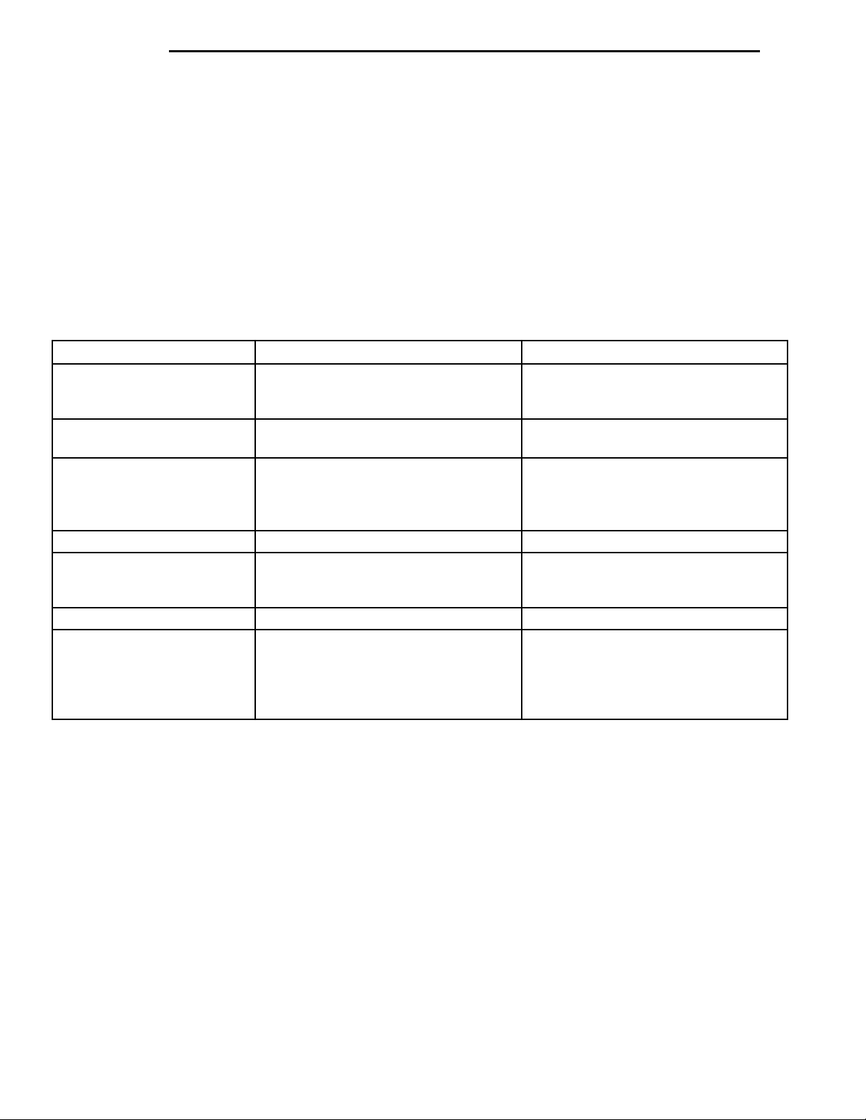
SERVICE DIAGNOSIS—CLUTCH GRAB/CHATTER
CONDITION POSSIBLE CAUSES CORRECTION
CLUTCH DISC FACING
COVERED WITH OIL OR
GREASE
NO FAULT FOUND WITH
CLUTCH
COMPONENTS
PARTIAL ENGAGEMENT OF
CLUTCH DISC
Oil leak at engine rear main or
transaxle input shaft seal
Too much grease applied to splines of
disc and input shaft
Problem actually related to suspension
or driveline component
Engine related problems Check EFI and ignition systems
Clutch cover, spring, or release fingers
bent, distorted (rough handling,
improper assembly)
Clutch disc damaged or distorted Replace w/modular clutch assembly
Clutch misalignment Check alignment and runout of
Drive the vehicle at normal speeds during road
test. Shift the transaxle through all gear ranges and
observe clutch action. If chatter, grab, slip, or
improper release is experienced, remove and inspect
the clutch components. If the problem is noise or
hard shifting, further diagnosis may be needed. The
transaxle or other driveline components may actually
be at fault.
Correct leak and replace w/modular
clutch assembly
Apply lighter coating of grease to
splines
Further diagnosis required. Check
engine/transmission mounts,
suspension attaching parts and other
driveline components as needed.
Replace w/modular clutch assembly
flywheel, disc, or cover. Check clutch
housing to engine dowels and dowel
holes for damage. Correct as
necessary.
Page 5
PL CLUTCH 6 - 5
DIAGNOSIS AND TESTING (Continued)
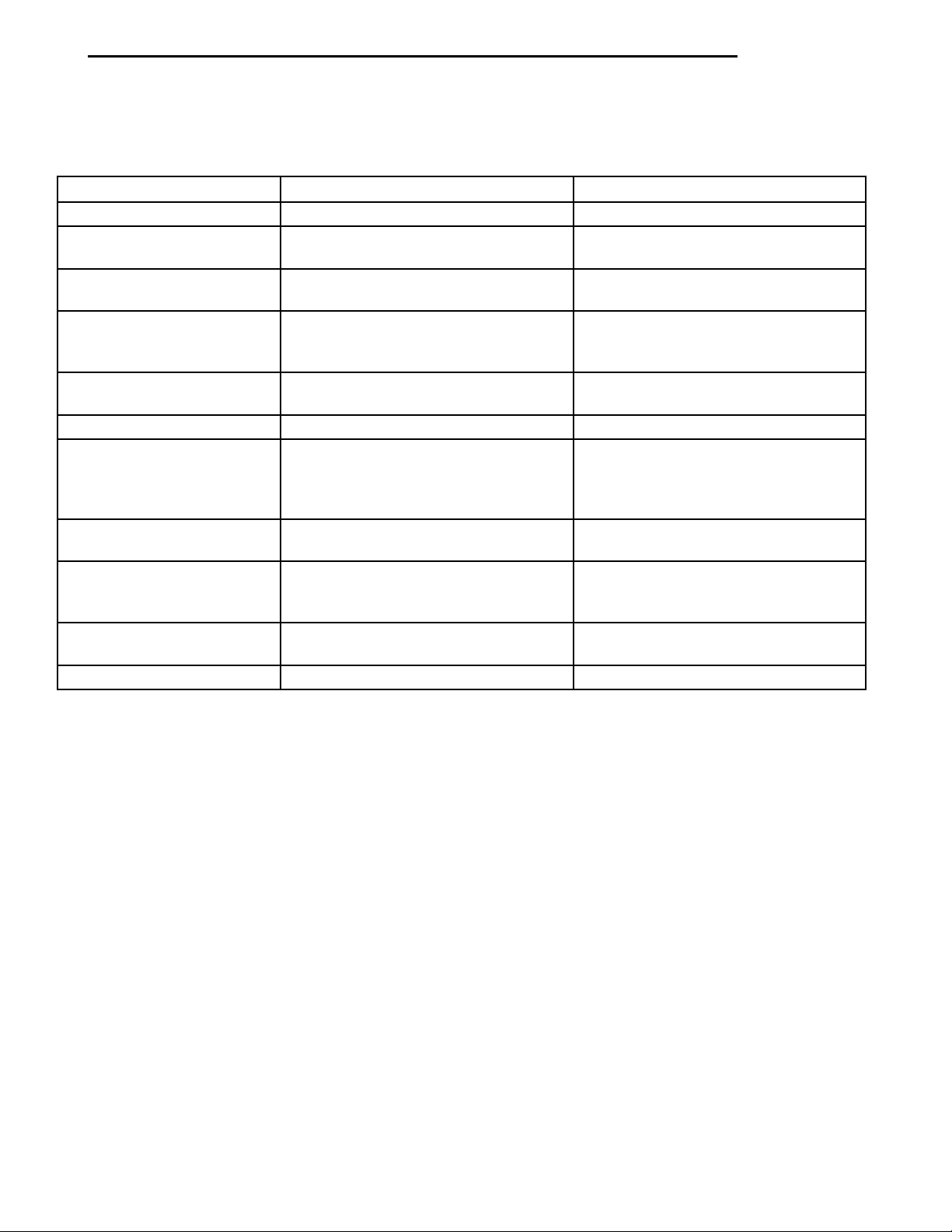
SERVICE DIAGNOSIS—CLUTCH SLIPS
CONDITION POSSIBLE CAUSES CORRECTION
DISC FACING WORN OUT Normal wear. Replace w/modular clutch assembly.
CLUTCH DISC FACING
CONTAMINATED WITH OIL
OR GREASE
CLUTCH IS RUNNING
PARTIALLY DISENGAGED
CLUTCH DISC FACINGS
HAVE FRACTURED INTO
SMALL PIECES
Driver frequently rides (slips) clutch,
results in rapid wear overheating.
Insufficient clutch cover diaphragm
spring tension
Leak at rear main oil seal or transaxle
input shaft seal
Excessive amount of grease applied to
input shaft splines
Road splash, water entering housing Seal housing. Inspect clutch assembly.
Release bearing sticking or binding,
does not return to normal running
position.
Cable self-adjuster mechanism sticking
or binding causing high preload
Driver performs a 5-1 downshift at
vehicle speed in excess of 60 miles
per hour
Leak at rear main or transaxle input
shaft seal
Excessive heat from slippage Replace w/modular clutch assembly
Replace w/modular clutch assembly
Replace w/modular clutch assembly
Replace leaking seals. Replace
w/modular clutch assembly.
Apply less grease to input shaft.
Replace w/modular clutch assembly
Verify that bearing is actually binding.
Then, replace bearing and transmission
front bearing retainer if sleeve surface
is damaged.
Verify that self-adjuster is free to move
Alert driver to problem cause. Replace
w/modular clutch assembly.
Replace w/modular clutch assembly.
Replace seal.
Page 6
6 - 6 CLUTCH PL
DIAGNOSIS AND TESTING (Continued)
SERVICE DIAGNOSIS—IMPROPER CLUTCH RELEASE
CONDITION POSSIBLE CAUSES CORRECTION
CLUTCH DISC BINDS ON INPUT
SHAFT SPLINES
CLUTCH DISC RUSTED TO
FLYWHEEL AND/OR PRESSURE
PLATE
CLUTCH WILL NOT DISENGAGE
PROPERLY
Clutch disc hub splines damaged
during installation
Input shaft splines rough, damaged. Clean input shaft splines. Then lube.
Corrosion or rust formations on
splines of input shaft and disc
Occurs in vehicles stored or not
driven for extended period of time.
Also occurs after steam cleaning if
vehicle is not used for extended
period.
Disc bent, distorted during transaxle
installation
Clutch cover diaphragm spring
damaged during transaxle
installation
Release fork bent, loose, or
damaged
Clutch cable binding or routed
incorrectly
Self-adjuster in cable not functioning
properly, resulting in excess cable
slack
Clean, smooth, and lubricate disc
and shaft splines. Replace
w/modular clutch assembly and/or
input shaft if splines are severely
damaged.
Clean input shaft splines and disc
splines, then lube
Replace w/modular clutch assembly
Replace w/modular clutch assembly
Replace w/modular clutch assembly
Replace fork if worn or damaged
Check and correct cable routing
Pull on cable conduit at transaxle (as
if disconnecting cable) to check
adjuster operation
SERVICE DIAGNOSIS–CLUTCH PEDAL NOISE
CONDITION POSSIBLE CAUSES CORRECTION
CLUTCH PEDAL MAKES
REPEATED “POP” NOISE IN THE
FIRST INCH OF TRAVEL
CLUTCH PEDAL SQUEAKS
WHEN DEPRESSED TO FLOOR
Self-adjusting mechanism in cable
defective
Pedal bushings worn out or
inadequate lubrication
Clutch pedal return spring worn out Replace return spring
Replace clutch cable
Replace or lubricate bushings
Page 7
PL CLUTCH 6 - 7
DIAGNOSIS AND TESTING (Continued)
DRIVE PLATE MISALIGNMENT
Common causes of misalignment are:
• Heat warping
• Mounting drive plate on a dirty crankshaft
flange
• Incorrect bolt tightening
• Improper seating on the crankshaft shoulder
• Loose crankshaft bolts
Clean the crankshaft flange before mounting the
drive plate. Dirt and grease on the flange surface
may misalign the flywheel, causing excessive runout.
Use new bolts when mounting drive plate to crankshaft. Tighten drive plate bolts to specified torque
only. Over-tightening can distort the drive plate hub
causing excessive runout.
CLUTCH COVER AND DISC RUNOUT
Check condition of the clutch cover before installation. A warped cover or diaphragm spring will cause
grab and/or incomplete release or engagement. Use
care when handling the clutch assembly. Impact can
distort the cover, diaphragm spring, and release fingers.
CLUTCH CHATTER COMPLAINTS
For all clutch chatter complaints, do the following:
(1) Check for loose, misaligned, or broken engine
and transmission mounts. If present, they should be
corrected at this time. Test vehicle for chatter. If
chatter is gone, there is no need to go any further. If
chatter persists:
(2) Check to see if clutch cable routing is correct
and operates smoothly.
(3) Check for loose connections in drive train. Correct any problems and determine if clutch chatter
complaints have been satisfied. If not:
(4) Remove transaxle. See Group 21, Manual Transaxle for procedure.
(5) Check to see if the release bearing is sticky or
binding. Replace bearing, if needed.
(6) Check linkage for excessive wear on the pivot
stud and fork fingers. Replace all worn parts.
(7) Check clutch assembly for contamination (dirt,
oil). Replace clutch assembly, if required.
(8) Check to see if the clutch disc hub splines are
damaged. Replace with new clutch assembly, if necessary.
(9) Check input shaft splines for damage. Replace,
if necessary.
(10) Check for uneven wear on clutch fingers.
(11) Check for broken clutch cover diaphragm
spring fingers. Replace with new clutch assembly, if
necessary.
CLASH–INTO–REVERSE COMPLAINTS
Certain NV T350 (A-578) manual transaxles are
equipped with a reverse brake. It prevents clash
when shifting into reverse, but only if the vehicle is
not moving. See Group 21, Transaxle for further
diagnosis.
(1) Depress clutch pedal to floor and hold. After
three seconds, shift to reverse. If clash is present,
clutch has excessive spin time, and the reverse brake
may not be functioning.
(2) Remove transaxle. See Group 21, Manual Transaxle for procedure.
(3) Check the input shaft spline, clutch disc
splines, and release bearing for dry rust. If present,
clean rust off and apply a light coat of bearing grease
to the input shaft splines. Apply grease on the input
shaft splines only where the clutch disc slides. Verify
that the clutch disc slides freely along the input shaft
spline.
(4) Check to see if the clutch disc hub splines are
damaged, and replace with new clutch assembly if
required.
(5) Check the input shaft for damaged splines.
Replace as necessary.
(6) Check for broken clutch cover diaphragm
spring fingers.
(7) Install clutch assembly and transaxle.
BELLHOUSINGCLUTCHCABLEEGRTUBE
REMOVAL AND INSTALLATION
CLUTCH CABLE
REMOVAL
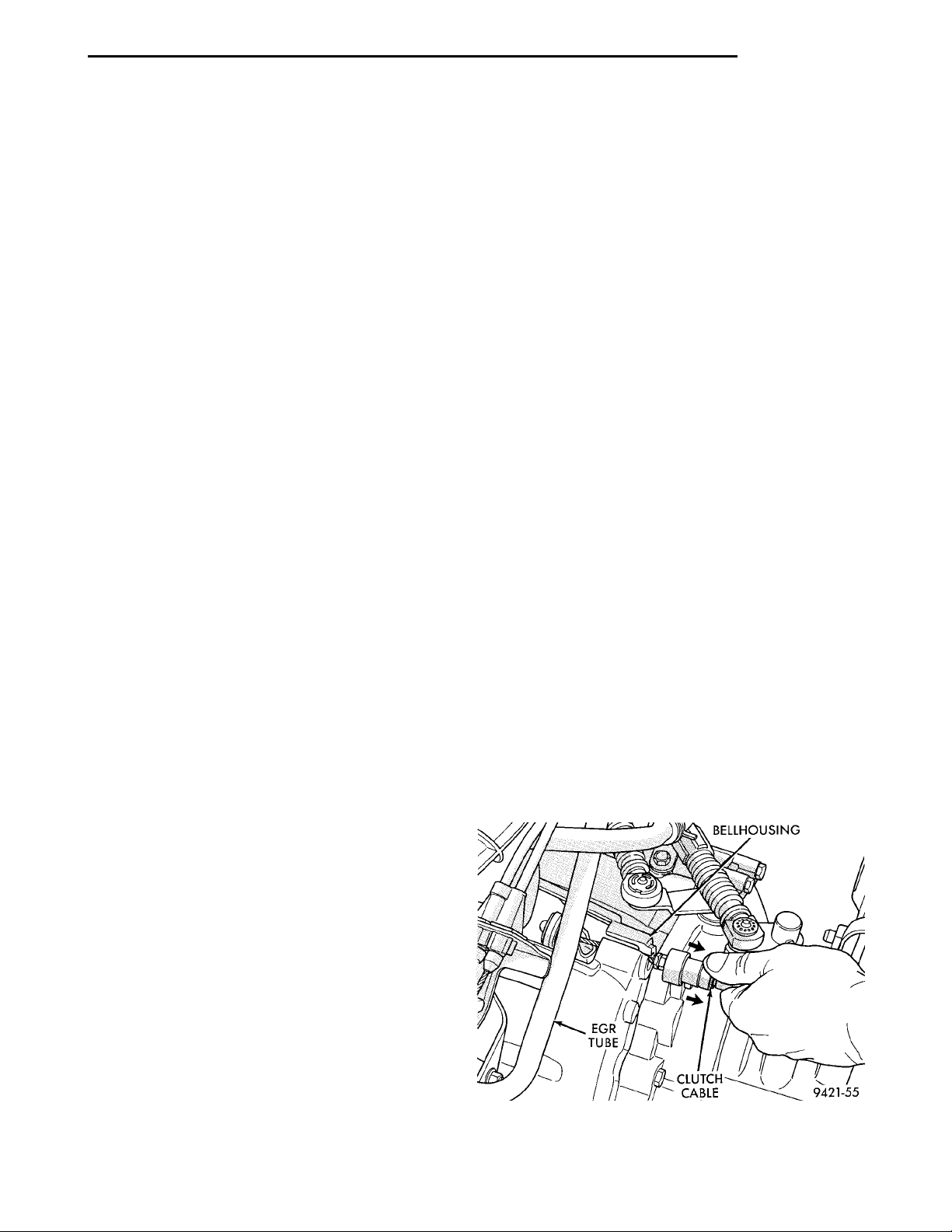
(1) Pull up and remove Power Distribution Center.
(2) Remove clutch cable inspection cover.
(3) Pull back on clutch cable housing and disengage cable from housing (Fig. 4).
Fig. 4 Cable at Transaxle
Page 8
6 - 8 CLUTCH PL
REMOVAL AND INSTALLATION (Continued)
(4) Guide cable through slot in transaxle and dis-
connect cable from release lever.
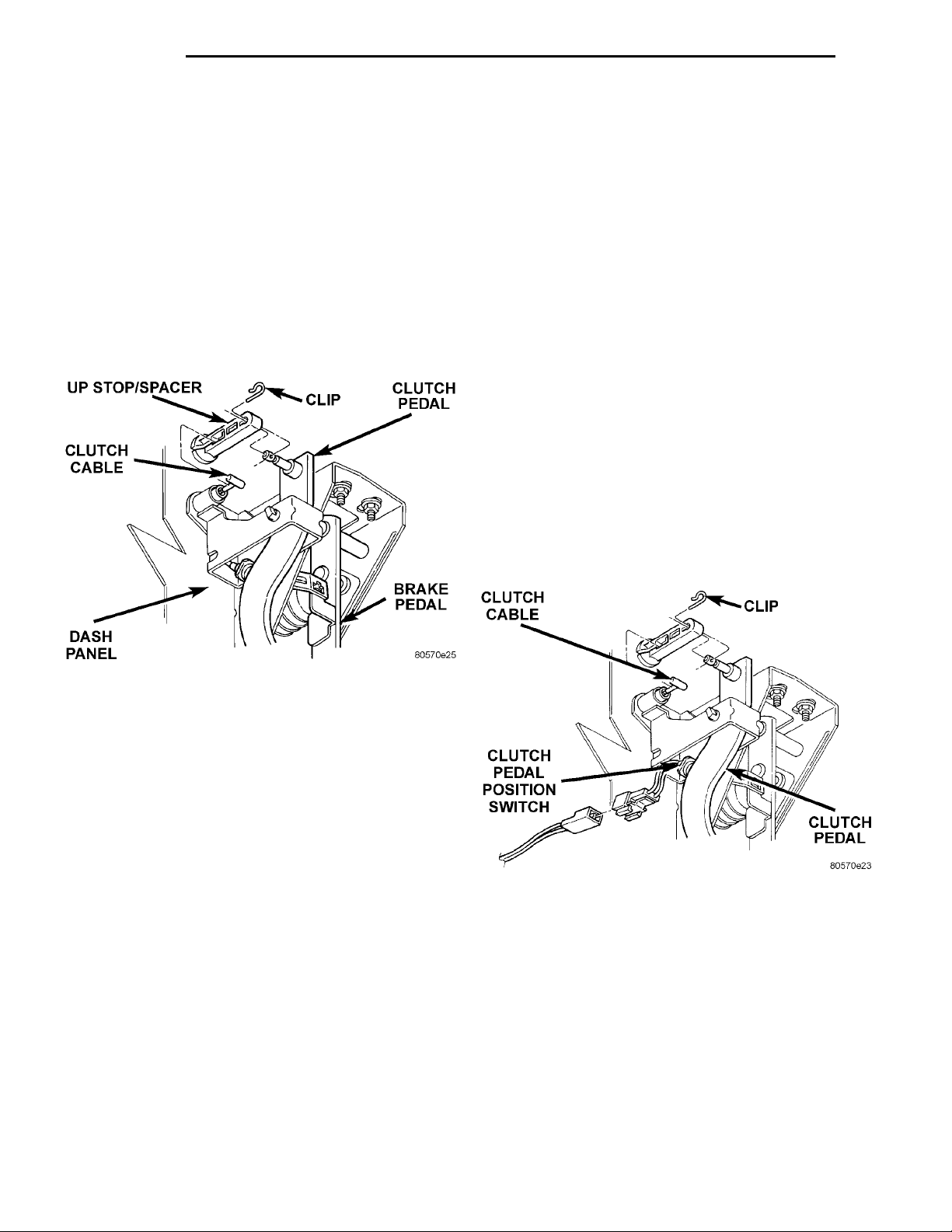
(5) Disconnect clutch cable up-stop/spacer with
cable strand from clutch pedal (Fig. 5).
NOTE: Depressing the clutch pedal provides
access to the clutch cable strand. Disconnect the
cable up-stop/spacer from the pedal pivot pin by
removing the retaining clip at the top of the clutch
pedal. Wedge a flat–blade pry tool between the pin
UP STOP/SPACER CLIP CLUTCH PEDALBRAKE PEDALDASH PANELCLUTCH CABLE
and the retaining tab. While holding the tab slightly
separated from the pin, pull the upstop/spacer off
the pedal. Now remove the cable end from the
upstop/spacer.
ADJUSTER MECHANISM FUNCTION CHECK
(1) With slight pressure, pull the clutch release
lever end of the cable to draw the cable taut. Push
the clutch cable housing toward the dash panel (With
less than 25 lbs. of effort, the cable housing should
move 30-50mm.). This indicates proper adjuster
mechanism function. If the cable does not adjust,
determine if the mechanism is properly seated on the
bracket.
(2) If the adjust mechanism functions properly,
guide the cable through the slot in the transaxle
housing. Connect cable to release lever, seating the
cupped washer securely on lever tangs.
(3) Pull back on clutch cable housing and insert
into transaxle housing (Fig. 4).
(4) Reinstall cable inspection cover and PDC.
Check clutch pedal position switch operation.
CLUTCH PEDAL POSITION SWITCH
The clutch pedal position switch is mounted to a
bracket located behind the clutch pedal. The switch
is held in place by four plastic wing tabs.
able. The pedal blade contacts the switch in the down
position (Fig. 6).
CLUTCH CABLE CLIP CLUTCH PEDALCLUTCHPEDAL POSI-TION SWITCH
The clutch pedal position switch IS NOT adjust-
Fig. 5 Cable End Removal
CAUTION: Do not pull on the clutch cable to
remove it from the dash panel. Damage to the cable
self-adjuster may occur.
(6) Use a slight twisting motion while grasping the
grommet and body to remove the cable from the dash
panel and clutch bracket.
(7) A screwdriver may be required to dislodge the
cable grommet from the dash panel. Use caution to
avoid damage to the cable grommet.
INSTALLATION
(1) Using a slight twisting motion, insert the self–adjuster mechanism end of the clutch cable through
the dash panel hole and into the bracket.
(2) Seat the cylindrical part of the cable grommet
in the dash panel. Be sure the self–adjuster is firmly
seated against the clutch bracket to ensure proper
adjuster mechanism function.
(3) Connect the clutch cable to the up-stop/spacer.
(4) Connect the up-stop/spacer to the clutch pedal.
(5) Perform the Adjuster Mechanism Function
Check before finishing installation.
Fig. 6 Clutch Pedal Position Switch and
Components
REMOVAL
(1) Disconnect electrical harness to switch connec-
tor.
(2) Depress wing tabs on switch and push switch
out of mounting bracket. Then slide wires through
slot in bracket.
INSTALLATION
(1) Slide switch wires through slot in switch
bracket.
(2) Line up switch tab with slot in switch bracket
and push switch into position. Do not pull on the
Page 9
PRESSURE
PLATE
DOWELS (3)FLYWHEEL
PL CLUTCH 6 - 9
REMOVAL AND INSTALLATION (Continued)
switch wires to seat switch into bracket, switch damage may occur.
(3) Attach switch wiring harness to vehicle wiring
harness.
(4) After installation, the switch must be checked
for proper operation. Refer to Diagnosis and Testing
section for proper testing procedures.
CLUTCH ASSEMBLY
Neon vehicles produced at the Toluca assembly
plant, in Mexico, have conventional clutch and flywheel assemblies. Vehicles produced at Belvidere
assembly plant have modular clutch assemblies.
TOLUCA BUILT VEHICLES
The transaxle must be removed to service the
clutch disc, flywheel, clutch cover and/or the release
bearing and lever.
REMOVAL
(1) Remove transaxle. See Group 21, Manual Transaxle, for procedure.
(2) Mark clutch cover and flywheel, to maintain
their same relative positions when installing clutch
assembly.
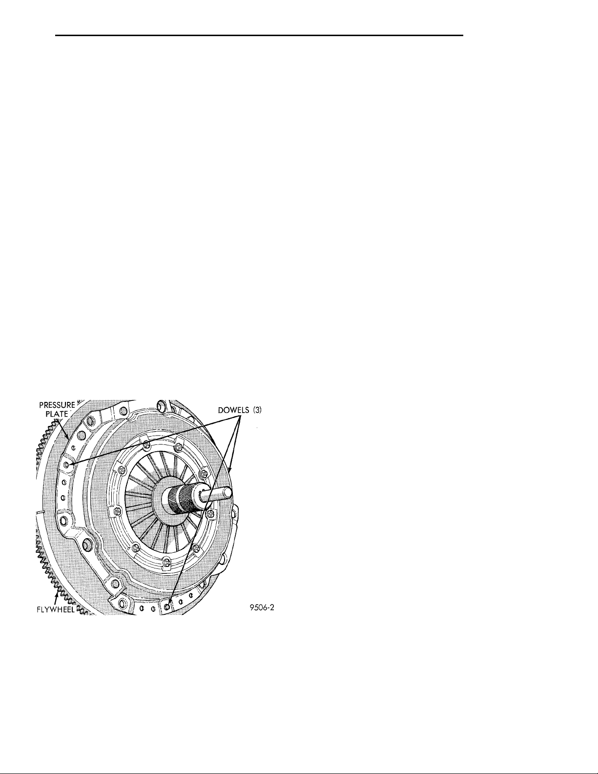
(3) Insert Clutch Disc Aligning Tool 6724 through
the clutch disc hub to prevent the clutch disc from
falling and damaging the facings (Fig. 7).
Fig. 7 Clutch Disc Aligning Tool
(4) Loosen clutch cover attaching bolts, one or two
turns at a time, in a crisscross pattern. This will
release spring pressure evenly and avoid cover damage.
CAUTION: Do not touch the clutch disc facing with
oily or dirty hands. Oil or dirt transferred from your
hands onto the clutch disc facing may cause clutch
chatter.
(5) Remove the clutch pressure plate and cover
assembly and disc from flywheel. Handle carefully to
avoid contaminating the friction surfaces.
INSPECTION
(1) Inspect for oil leakage through engine rear
main bearing oil seal and transaxle input shaft seal.
If leakage is noted, it should be corrected at this
time.
(2) The friction faces of the flywheel and pressure
plate should not have excessive discoloration, burned
areas, cracks, deep grooves, or ridges. Replace parts
as required.
(3) Clean the flywheel face with medium sandpaper (80-180 grade), then wipe the surface with mineral spirits. If the surface is severely scored, heat
checked, cracked or warped, replace the flywheel.
CAUTION: Do not flat-machine the flywheel face.
The surface profile is tapered.
(4) The heavy side of the flywheel is indicated by a
daub of white paint near the outside diameter. To
minimize the effects of flywheel unbalance, perform
the following installation procedure:
• Loose assemble the flywheel to the crankshaft.
Use new flywheel attaching bolts which have sealant
on the threads. If new bolts are not available, apply
Loctite sealant to the threads of the original bolts.
This sealant is required to prevent engine oil leakage.
• Rotate the flywheel and crankshaft until the
daub of white paint (heavy side) is at the 12 o’clock
position.
• Torque flywheel attaching bolts to 95 N·m (70 ft.
lbs.). Use a crisscross pattern when tightening bolts.
(5) The disc assembly should be handled without
touching the facings. Replace disc if the facings show
evidence of grease or oil soakage, or wear to within
less than .20 mm (.008 inch) of the rivet heads. The
splines on the disc hub and transaxle input shaft
should be a snug fit without signs of excessive wear.
Metallic portions of disc assembly should be dry,
clean, and not discolored from excessive heat. Each of
the arched springs between the facings should not be
broken and all rivets should be tight.
(6) Wipe the friction surface of the pressure plate
with mineral spirits.
(7) Using a straight edge, check pressure plate for
flatness. The pressure plate friction area should be
FLAT TO SLIGHTLY CONCAVE, with the inner
diameter 0.000 mm to 0.1 mm (0.000 in. to 0.0039
in.) below the outer diameter. It should also be free
Page 10
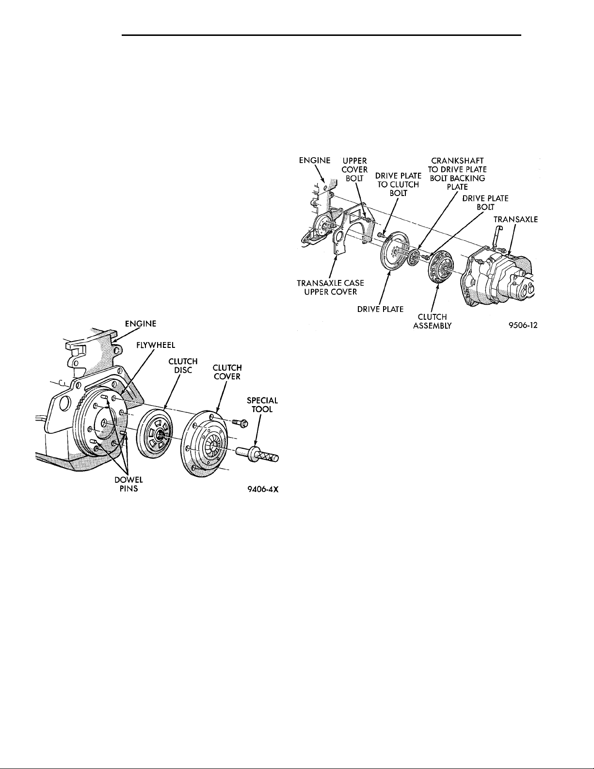
DOWEL PINSENGINEFLYWHEELCLUTCH DISC CLUTCH COVERSPECIAL TOOL
ENGINE UPPER COVERBOLT DRIVE PLATETO CLUTCHBOLT CRANKSHAFT TO DRIVEPLATE BOLT BACKINGPLATEDRIVE PLATE BOLTTRANSAXLECLUTCHASSEMBLYDRIVE PLATETRANSAXLE CASEUPPER COVER
6 - 10 CLUTCH PL
REMOVAL AND INSTALLATION (Continued)
from discoloration, burned areas, cracks, grooves, or
ridges.
(8) Using a surface plate, test cover for flatness.
All sections around attaching bolt holes should be in
contact with surface plate within .015 inch.
(9) The cover should be a snug fit on flywheel dowels. If the clutch assembly does not meet these
requirements, it should be replaced.
INSTALLATION
(1) Mount clutch assembly on flywheel with disc
centered with tool 6724, being careful to properly
align dowels and the alignment marks made before
removal. The flywheel side of the clutch disc is
marked for proper installation. If new clutch or flywheel is installed, align orange cover balance spot as
close as possible to orange flywheel balance spot.
Apply pressure to the alignment tool. Center the tip
of the tool into the crankshaft and the sliding cone
into the clutch fingers. Tighten the clutch attaching
bolts sufficiently to hold the disc in position (Fig. 8).
(5) Remove transaxle. See Group 21, Manual Tran-
saxle, for procedure.
(6) The transaxle and modular clutch come out as
an assembly.
(7) Remove the modular clutch assembly from the
transaxle input shaft (Fig. 9). Handle carefully to
avoid contaminating the friction surfaces.
Fig. 9 Clutch Components
INSPECTION
(1) Inspect for oil leakage through engine rear
main bearing oil seal and transaxle input shaft seal.
If leakage is noted, it should be corrected at this
time.
Fig. 8 Clutch Installation
(2) To avoid distortion of the clutch cover, bolts
should be tightened a few turns at a time. Use a
crisscross pattern, until all bolts are seated. Tighten
bolts to 28 N·m (250 in. lbs.) following a crisscross
pattern sequence. Remove clutch disc alignment tool.
(3) Install transaxle. See Group 21, Manual Transaxle for procedures.
BELVIDERE BUILT VEHICLES
The transaxle must be removed to service the modular clutch disc assembly and lever.
REMOVAL
(1) Remove the starter wiring. Remove the starter
assembly.
(2) Remove the rear transaxle support bracket.
(3) Remove the front transaxle support bracket.
(4) Remove modular clutch retaining bolts.
INSTALLATION
(1) Mount modular clutch assembly onto input
shaft.
(2) Install transaxle. See Group 21, Manual Tran-
saxle, for procedure.
NOTE: Use new bolts when mounting modular
clutch assembly to drive plate.
(3) To avoid distortion of the drive plate, bolts
should be tightened a few turns at a time. Use a
crisscross pattern, until all bolts are seated. Tighten
bolts to 75 N·m (55 ft. lbs.) following a crisscross pattern sequence.
(4) Install clutch inspection cover.
(5) Install transaxle lower support brackets.
(6) Install starter assembly.
RELEASE BEARING AND FORK
Remove the transaxle from the vehicle. See Group
21, Transaxle for removal and installation procedures.
REMOVAL
(1) Move the lever and bearing assembly to a vertical in-line position. Grasp the release lever with
Page 11

PL CLUTCH 6 - 11
REMOVAL AND INSTALLATION (Continued)
two hands in the pivot stud socket area. Pull with
even pressure and the lever will pop off the pivot–stud. Do not use a screwdriver or pry bar to pop off
the lever. This may damage the spring clip on the
lever.
(2) As a unit, remove the fork from the bearing
thrust plate. Be careful not to damage retention tabs
on bearing.
(3) Examine the condition of the bearing. It is
pre-lubricated and sealed and should not be
immersed in oil or solvent.
(4) The bearing should turn smoothly when held in
the hand under a light thrust load. A light drag
caused by the lubricant fill is normal. If the bearing
is noisy, rough, or dry, replace the complete bearing
assembly with a new bearing.
(5) Check the condition of the pivot stud spring
clips on back side of clutch fork. If the clips are broken or distorted, replace the clutch fork.
INSTALLATION
(1) The pivot ball pocket in the fork is Teflon
coated and should be installed WITHOUT any lubricant such as grease. Using grease will break down
the Teflon coating. Be sure the ball stud and fork
pocket are clean of contamination and dirt.
(2) Assemble the fork to the bearing. The small
pegs on the bearing must go over the fork arms.
(3) Slide the bearing and fork assembly onto the
input shaft bearing retainer, as a unit.
(4) Snap the clutch fork onto the pivot ball.
(5) Reinstall transaxle assembly. Refer to Group
21, Transaxle for further information.
GREASE CONTAMINATION
Grease contamination is usually a product of overlubrication. During clutch service, apply only a small
amount of grease to the input shaft splines. Excess
grease may be thrown off during operation, contaminating the disc.
ROAD SPLASH/WATER CONTAMINATION
Road splash contamination is usually caused by
driving the vehicle through deep water puddles.
Water can be forced into the clutch housing, causing
clutch components to become contaminated. Facing of
disc will absorb moisture and bond to the flywheel
and/or, pressure plate, if vehicle is allowed to stand
for some time before use. If this condition occurs,
replacement of clutch assembly may be required.
Drive the vehicle until normal clutch operating temperature has been obtained. This will dry off disc
assembly, pressure plate, and flywheel.
CLEANING PRECAUTIONS
Condensation from steam vapors tend to accumulate on the internal clutch mechanism when the vehicle is steam cleaned. Facing of disc will absorb
moisture and will bond to flywheel and/or pressure
plate, if vehicle is allowed to stand for some time
before use. If this condition occurs, it may require
replacement of clutch assembly. After cleaning, drive
the vehicle to its normal clutch operating temperature. This will dry off disc assembly, pressure plate,
and flywheel.
ADJUSTMENTS
CLEANING AND INSPECTION
CLUTCH CONTAMINATION
Fluid contamination is a frequent cause of clutch
malfunctions. Oil, grease, water, or other fluids on
the clutch contact surfaces will cause faulty operation.
During inspection, note if any components are contaminated. Look for evidence of oil, grease, or water/
road splash on clutch components.
OIL CONTAMINATION
Oil contamination indicates a leak at the rear main
seal and/or transaxle input shaft. Oil leaks produce a
residue of oil on the transaxle housing interior, clutch
cover and flywheel. Heat buildup caused by slippage
can bake the oil residue onto the components. This
glaze-like residue ranges in color from amber to
black.
CLUTCH CABLE
The manual transaxle clutch release system has a
unique self-adjusting mechanism to compensate for
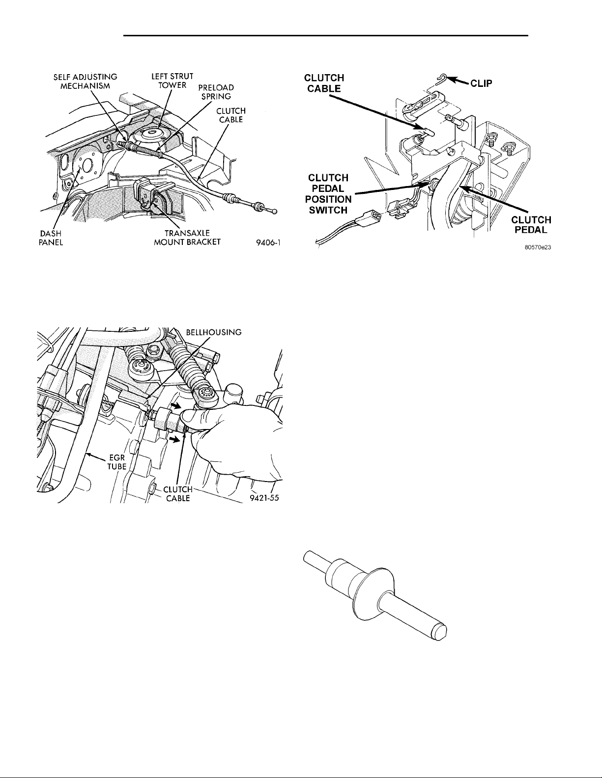
clutch disc wear (Fig. 10). This adjuster mechanism
is located within the clutch cable assembly. The preload spring maintains tension on the cable. This tension keeps the clutch release bearing continuously
loaded against the fingers of the clutch cover assembly.
ADJUSTER MECHANISM FUNCTION CHECK
(1) With slight pressure, pull the clutch release
lever end of the cable to draw the cable taut. Push
the clutch cable housing toward the dash panel. With
less than 25 lbs. of effort the cable housing should
move 30-50mm. This indicates proper adjuster mechanism function. If the cable does not adjust, determine if the mechanism is properly seated on the
bracket.
(2) If the adjust mechanism functions properly,
guide the cable through the slot in the transaxle
Page 12
DASH PANELSELF ADJUSTING MECHA-NISM LEFT STRUT TOWER PRELOAD SPRINGCLUTCH CABLETRANSAXLE MOUNTBRACKET
BELLHOUSINGCLUTCHCABLEEGRTUBE
CLUTCH CABLE CLIP CLUTCH PEDALCLUTCHPEDAL POSI-TION SWITCH
6 - 12 CLUTCH PL
ADJUSTMENTS (Continued)
Fig. 10 Clutch Cable Routing
housing. Connect cable to release lever, seating the
cupped washer securely on lever tangs.
(3) Pull back on clutch cable housing and insert
into transaxle housing (Fig. 11).
Fig. 11 Cable at Transaxle
(4) Reinstall cable inspection cover and air cleaner
assembly. Check clutch pedal position switch operation.
Fig. 12 Clutch Pedal Position Switch and
Components
SPECIFICATIONS
TORQUE
MODULAR CLUTCH
DESCRIPTION TORQUE
Drive Plate To Clutch Bolts ....75N·m(55ft.lbs.)
Drive Plate To Crankshaft Bolts . 95 N·m (70 ft. lbs.)
Clutch Pedal Pivot Shaft Nut . . . 41 N·m (30 ft. lbs.)
CONVENTIONAL CLUTCH
DESCRIPTION TORQUE
Clutch Cover Bolts ..........28N·m(250 in. lbs.)
Flywheel to Crankshaft Bolts . . . 95 N·m (70 ft. lbs.)
Clutch Pedal Pivot Shaft Nut . . . 41 N·m (30 ft. lbs.)
SPECIAL TOOLS
CLUTCH
CLUTCH PEDAL POSITION SWITCH
The clutch pedal position switch is mounted to a
bracket located behind the clutch pedal. The switch
is held in place by four plastic wing tabs.
The clutch pedal position switch IS NOT adjustable. The pedal blade contacts the switch in the down
position (Fig. 12).
Clutch Disc Aligner-6724
 Loading...