

Page 1

PL BRAKES 5 - 1
BRAKES
CONTENTS
page page
ANTILOCK BRAKE SYSTEM–BENDIX ABX-4 .. 68
BASE BRAKE SYSTEM .................... 2
GENERAL INFORMATION
INDEX
page
GENERAL INFORMATION
BASE BRAKE SYSTEM DESCRIPTION ....... 1
GENERAL INFORMATION
BASE BRAKE SYSTEM DESCRIPTION
Typical brake equipment consists of:
• Double pin floating caliper disc front brakes.
• Rear automatic adjusting drum brakes.
• Brake Fluid Level Switch.
• Master cylinder.
• Vacuum power booster.
• Double pin floating caliper rear disc brakes are
available on some models.
• Hand operated auto adjust park brake lever.
• Front disc brake pads are semi-metallic.
Vehicles equipped with an Antilock Brake System
(ABS) use a system designated ABX-4 and is supplied by Bendix. This system shares the base brake
hardware with vehicles not equipped with ABS. A
GENERAL INFORMATION .................. 1
vehicle equipped with ABS does however use a different vacuum booster, master cylinder and brake tubes.
Also included in the ABS system is a hydraulic control unit (HCU), four wheel speed sensors, and an
electronic controller (CAB). These components will be
described in detail in the Bendix ABX 4 brake section
in this group of the service manual.
The hydraulic brake system is diagonally split on
both the Non-ABS and ABS braking system. With the
left front and right rear brakes on one hydraulic system and the right front and left rear on the other.
The master cylinder is anodized, lightweight aluminum. On vehicles equipped with front disc brakes
and rear drum brakes, the master cylinder bore is
21.0 mm. On vehicles equipped with four wheel disc
brakes, the master cylinder bore is 7/8”.
Page 2

5 - 2 BRAKES PL
BASE BRAKE SYSTEM
INDEX
page page
DESCRIPTION AND OPERATION
CHASSIS TUBES AND HOSES ............. 6
FRONT DISC BRAKES .................... 2
MASTER CYLINDER ..................... 6
PARKING BRAKES ...................... 4
PROPORTIONING VALVES ................ 5
REAR DISC BRAKES ..................... 4
REAR DRUM BRAKES .................... 4
REAR WHEEL HUB AND BEARING ASSEMBLY . 8
RED BRAKE WARNING LAMP .............. 7
STOP LAMP SWITCH .................... 8
VACUUM BOOSTER ..................... 7
DIAGNOSIS AND TESTING
BRAKE FLUID CONTAMINATION ........... 19
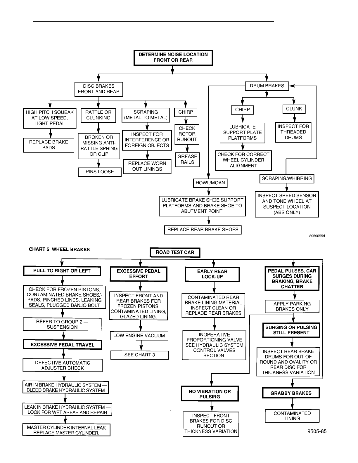
BRAKE SYSTEM BASIC DIAGNOSIS GUIDE . . . 9
BRAKE SYSTEM DIAGNOSIS CHARTS ...... 10
DRUM BRAKE AUTOMATIC ADJUSTER ...... 14
PROPORTIONING VALVES ............... 15
RED BRAKE WARNING LAMP TEST ........ 19
ROTOR THICKNESS AND RUNOUT ......... 14
STOP LAMP SWITCH TEST PROCEDURE .... 19
SERVICE PROCEDURES
BRAKE BLEEDING ...................... 19
BRAKE DRUM MACHINING ............... 23
BRAKE FLUID LEVEL CHECK ............. 19
BRAKE ROTOR MACHINING .............. 21
BRAKE TUBE REPAIR ................... 24
MASTER CYLINDER BLEEDING ........... 21
PARK BRAKE LEVER AUTO ADJUSTER
MECHANISM ......................... 23
REMOVAL AND INSTALLATION
CHASSIS TUBES AND HOSES ............ 46
FRONT DISC BRAKE CALIPER ............ 26
FRONT DISC BRAKE SHOES ............. 27
MASTER CYLINDER .................... 40
PARK BRAKE CABLES .................. 49
PARK BRAKE LEVER ASSEMBLY .......... 47
PARK BRAKE LEVER OUTPUT CABLE ...... 49
PARK BRAKE SHOES WITH REAR DISC
BRAKES ............................ 54
PROPORTIONING VALVE (BASE BRAKES) . . . 46
REAR BRAKE DRUM .................... 33
REAR BRAKE SHOE SUPPORT PLATE ...... 36
REAR BRAKE SHOES ................... 34
REAR BRAKE WHEEL CYLINDER .......... 37
REAR DISC BRAKE CALIPER ............. 29
REAR DISC BRAKE SHOES .............. 31
REAR HUB/BEARING .................... 38
STOP LAMP SWITCH .................... 56
VACUUM BOOSTER .................... 42
WHEEL AND TIRE ASSEMBLY ............. 25
DISASSEMBLY AND ASSEMBLY
BRAKE FLUID LEVEL SWITCH ............ 57
BRAKE FLUID RESERVOIR ............... 56
FRONT AND REAR DISC BRAKE CALIPER . . . 58
WHEEL CYLINDER (REAR DRUM BRAKE) . . . 62
CLEANING AND INSPECTION
CHASSIS TUBES AND HOSES ............ 64
FRONT DISC BRAKES ................... 63
REAR DISC BRAKES .................... 63
REAR DRUM BRAKE WHEEL CYLINDER .... 64
REAR DRUM BRAKES ................... 64
REAR WHEEL HUB AND BEARING
ASSEMBLY .......................... 64
ADJUSTMENTS
PARKING BRAKE ADJUSTMENT ........... 65
REAR DRUM BRAKE SHOE ADJUSTMENT . . . 65
STOP LAMP SWITCH .................... 64
SPECIFICATIONS
BRAKE ACTUATION SYSTEM ............. 66
BRAKE FASTENER TORQUE
SPECIFICATIONS ..................... 66
BRAKE FLUID ......................... 65
SPECIAL TOOLS
BASE BRAKE SYSTEM .................. 67
DESCRIPTION AND OPERATION
FRONT DISC BRAKES
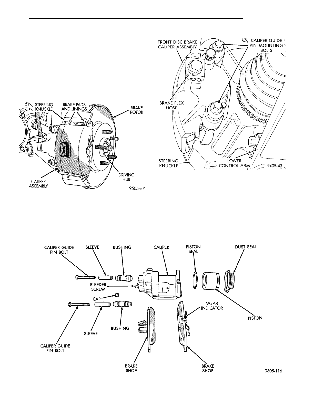
The front disc brakes (Fig. 1) and (Fig. 2) consists
of the following components:
• The driving hub
• Braking disc (rotor)
• Caliper assembly - single piston, floating type
• Brake shoes and linings
The double pin Kelsey-Hayes Calipers are mounted
directly to the steering knuckles and use no adapter.
The caliper is mounted to the steering knuckle using
bushings, sleeves and 2 guide pin bolts which thread
directly into bosses on the steering knuckle (Fig. 2)
and (Fig. 3).
Two machined abutments on the steering knuckle
position the caliper. The guide pin bolts, sleeves and
bushings control the side to side movement of the
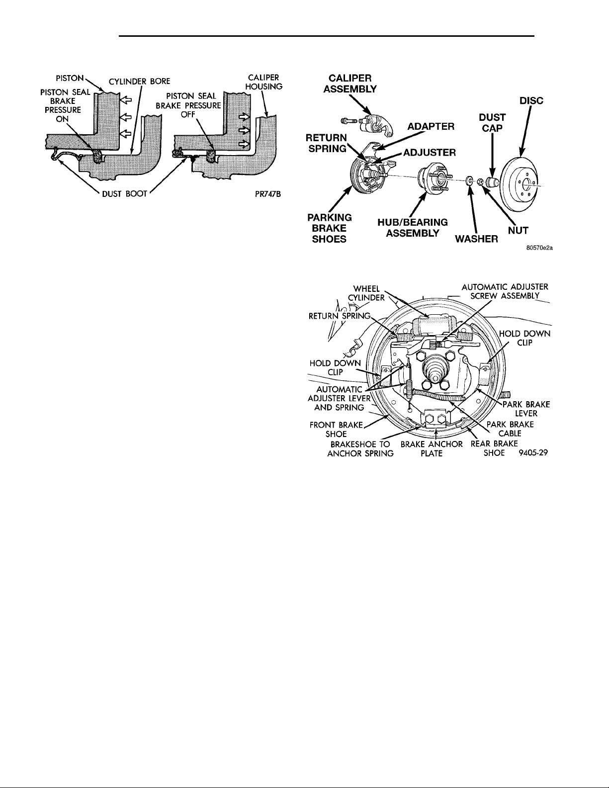
caliper. The piston seal is designed to pull the piston
back into the bore of the caliper when the brake
Page 3
STEERINGKNUCKLE BRAKE PADS ANDLININGS BRAKE ROTORDRIVING HUBCALIPER ASSEMBLY
CALIPER GUIDE PINBOLT SLEEVE BUSHING CALIPER PISTON SEAL DUST SEALPISTONWEAR INDI-CATORBRAKE SHOEBRAKESHOEBUSHINGSLEEVECALIPER GUIDE PINBOLT CAPBLEEDERSCREW
FRONT DISC BRAKECALIPER ASSEMBLY CALIPER GUIDE PINMOUNTING BOLTSBRAKE FLEXHOSESTEERINGKNUCKLE LOWER CONTROLARM
PL BRAKES 5 - 3
DESCRIPTION AND OPERATION (Continued)
pedal is released. This maintains the proper brake
shoe to rotor clearance (Fig. 4).
All the front brake forces generated during braking
of the vehicle is taken up directly by the steering
knuckles of the vehicle.
The caliper is a one piece casting with the inboard
side containing a single piston cylinder bore.
The front disc brake caliper piston (Fig. 2), is manufactured from a phenolic compound. The outside
diameter of the caliper piston is 54 mm.
Fig. 1 Front Disc Brake Caliper Assembly
A square cut rubber piston seal is located in a
machined groove in the caliper cylinder bore. This
provides a hydraulic seal between the piston and the
cylinder wall (Fig. 4).
Fig. 3 Front Disc Brake Caliper Mounting
A rubber dust boot is installed in the cylinder bore
opening and in a groove in the piston (Fig. 4). This
prevents contamination in the bore area.
As front disc brake linings wear, master cylinder
reservoir brake fluid level will drop. Fluid level
should be checked after replacing linings.
Front disc brakes are equipped with an audible
wear indicator (Fig. 2) on the outboard brake pad.
Fig. 2 Front Disc Brake Caliper (Exploded View)
Page 4
PISTON CYLINDER BOREPISTON SEALBRAKE PRES-SURE OFF CALIPERHOUSING DUST BOOT PISTONSEALBRAKEPRESSUREON
CALIPER ASSEMBLY ADAPTER DUST CAP DISCNUTWASHERHUB/BEARING ASSEM-BLYPARKING BRAKESHOESRETURNSPRING ADJUSTER
WHEEL CYLINDER AUTOMATIC ADJUSTERSCREW ASSEMBLYRETURN SPRINGHOLD DOWNCLIP HOLD DOWNCLIPAUTOMATICADJUSTER LEVERAND SPRING PARK BRAKELEVERPARK BRAKE CABLEFRONT BRAKESHOEBRAKE SHOE TO ANCHORSPRINGBRAKE ANCHOR PLATEREAR BRAKE SHOE
5 - 4 BRAKES PL
DESCRIPTION AND OPERATION (Continued)
Fig. 4 Piston Seal Function for Automatic
Adjustment
This sensor emits a sound when the brake lining
may need inspection and/or replacement.
Fig. 5 Rear Disc Brake Assembly Exploded View
REAR DISC BRAKES
The rear disc brakes are similar to the front disc
brakes, however, there are several distinctive features that require different service procedures. The
single piston, floating caliper rear disc brake assembly includes a hub and bearing assembly, adapter,
brake rotor, caliper, brake pads/linings. The parking
brake system on all vehicles equipped with rear disc
brakes consists of a small duo-servo drum brake
mounted to the caliper adapter. The drum brake
shoes expand out against a braking surface (hat section) on the inside area of the rotor.
Vehicles are equipped with a caliper assembly that
has a 34 mm (1.43 in.) piston and uses a solid nonvented rotor.
The caliper assembly on all applications float on
rubber bushings using internal metal sleeves which
are attached to the adapter using threaded guide pin
bolts.
The adapter and rotor shield are mounted to the
rear suspension knuckles of vehicle. The adapter is
used to mount the brake shoes and actuating cables
for the parking brake system. The adapter also
mounts the rear caliper assembly to the vehicle. The
adapter has two machined abutments which are used
to position and align the caliper and brake pads for
movement inboard and outboard (Fig. 5).
REAR DRUM BRAKES
The rear wheel drum brakes are a two shoe, internal expanding type with an automatic adjuster screw
(Fig. 6). The automatic adjuster screw is actuated
each time the brakes are applied. The automatic
adjuster screw is located directly below the rear
brake wheel cylinder.
PARKING BRAKES
All vehicles are equipped with a center mounted,
hand operated park brake lever. This lever is an
Fig. 6 Kelsey Hayes Rear Wheel Brake Assembly
(Left Side Shown)
auto-adjust type which continuously applies minimal
tension to the parking brake cables to keep them in
adjustment at all times. Due to this feature, the park
brake cable system does not require adjustment.
Proper parking brake system adjustment is obtained
by proper drum brake or drum-in-hat brake shoe
adjustment.
On vehicles equipped with rear drum brakes, the
rear wheel service brakes also act as the vehicle’s
parking brakes. The rear drum brake shoes, when
acting as parking brakes, are mechanically operated
using an internal actuating lever and strut which is
connected to a flexible steel cable. There is an individual park brake cable for each rear wheel, which
are joined using a park cable equalizer before terminating at the floor mounted, hand operated park
brake lever.
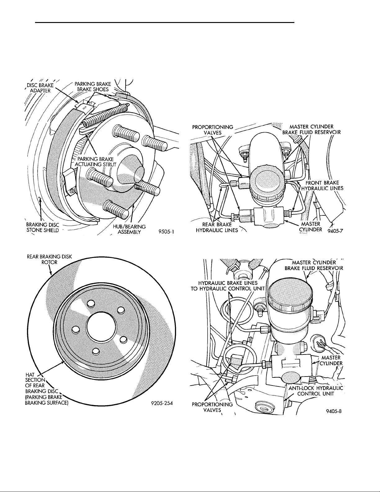
The parking brakes on vehicles equipped with rear
disc brakes consist of a small duo-servo brake assembly mounted to the disc brake caliper adapter (Fig.
7). The hat (center) section (Fig. 8) of the rear rotor
Page 5
DISC BRAKEADAPTER PARKING BRAKEBRAKE SHOESHUB/BEARING ASSEM-BLYBRAKING DISCSTONE SHIELD PARKING BRAKE ACTU-ATING STRUT
REAR BRAKINGDISK ROTOR
HAT SECTION OF
REAR BRAKING
DISC (PARKING
BRAKE BRAKING
SURFACE)
PL BRAKES 5 - 5
PROPORTIONINGVALVES MASTER CYLINDER BRAKEFLUID RESERVOIRFRONT BRAKEHYDRAULIC LINES MASTER CYLINDER
HYDRAULIC BRAKE LINES TOHYDRAULIC CONTROL UNIT MASTER CYLINDER BRAKEFLUID RESERVOIRMASTERCYLINDERANTI-LOCK HYDRAULICCONTROL UNITPROPORTIONINGVALVES
REAR BRAKE HYDRAULICLINES
DESCRIPTION AND OPERATION (Continued)
serves as the braking surface (drum) for the parking
brakes. This park brake application uses the same
operating cable configuration as the drum brake
equipped vehicles, but different cables.
tubes connect directly from the master cylinder (or
HCU) to the brake flex hose.
The non-ABS master cylinders are a four outlet
design with two screw-in proportioning valves
attached directly to the inboard side of the master
cylinder housing (Fig. 9).
The ABS master cylinders are a two outlet design
with the screw-in proportioning valves attached
directly to the Hydraulic Control Unit (HCU) (Fig.
10).
Fig. 7 Park Brake Assembly With Rear Disc Brakes
Fig. 8 Drum In Hat Rotor
PROPORTIONING VALVES
This vehicle uses screw-in proportioning valves at
the master cylinder or Hydraulic Control Unit
instead of the combination valve used in prior
designs. With this new design, the chassis brake
Fig. 9 Master Cylinder And Proportioning Valves For
Non ABS Equipped Vehicles
Fig. 10 Master Cylinder And Proportioning Valves
For Antilock Brake Equipped Vehicles
Proportioning valves balance front to rear braking
by controlling at a given ratio, the increase in rear
brake system hydraulic pressure above a preset level
Page 6
TO REAR BRAKE LINE TO MASTER CYLINDER ORHYDRAULIC CONTROL UNITO-RING SEALCOLORED IDENTIFI-CATION BAND
PROPORTIONINGVALVES MASTER CYLINDER BRAKEFLUID RESERVOIRFRONT BRAKEHYDRAULIC LINES MASTER CYLINDER
HYDRAULIC BRAKE LINES TOHYDRAULIC CONTROL UNIT MASTER CYLINDER BRAKEFLUID RESERVOIRMASTERCYLINDERANTI-LOCK HYDRAULICCONTROL UNITPROPORTIONINGVALVES
REAR BRAKE HYDRAULICLINES
5 - 6 BRAKES PL
DESCRIPTION AND OPERATION (Continued)
(split point). Under light pedal application, the proportioning valve allows full hydraulic pressure to be
applied to the rear brakes.
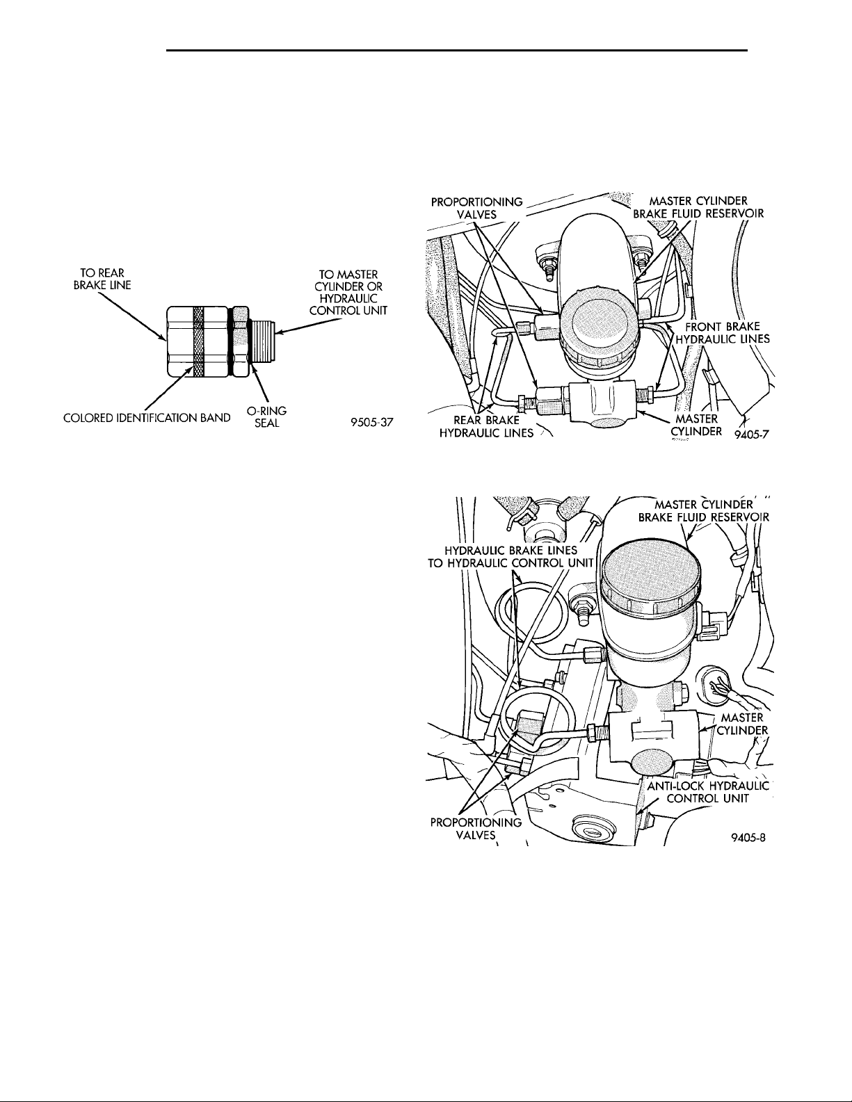
There are two proportioning valve assemblies used
in each vehicle. Due to differences in thread sizes,
each prop valve has a different part number. During
any service procedures identify valve assemblies by
supplier part number and or the color identification
band (Fig. 11).
Fig. 11 Proportioning Valve Identification
CHASSIS TUBES AND HOSES
The purpose of the chassis brake tubes and flex
hoses is to transfer the pressurized brake fluid developed by the master cylinder to the wheel brakes of
the vehicle. The chassis tubes are steel with a corrosion resistant coating applied to the external surfaces
and the flex hoses are made of reinforced rubber. The
rubber flex hoses allow for the movement of the vehicles suspension.
ing. It has a machined bore to accept the master cylinder piston and threaded ports with seats for
hydraulic brake line connections. The brake fluid reservoir of the master cylinder assembly is made of a
see through polypropelene type plastic.
Fig. 12 Master Cylinder For Non Anti-Lock Brake
Equipped Vehicles
MASTER CYLINDER
This vehicle is available with three different master cylinders. The vehicle uses screw-in proportioning
valves at the master cylinder or Hydraulic Control
Unit instead of the combination valve used in prior
designs. With this new design, the chassis brake
tubes connect directly from the master cylinder (or
HCU) to the brake flex hose.
Vehicles not equipped with ABS use a standard
compensating port design, while vehicles equipped
with ABS use a center valve design master cylinder.
In addition, the non-ABS master cylinders are a four
outlet design with two screw-in proportioning valves
attached directly to the inboard side of the master
cylinder housing (Fig. 12). The ABS master cylinders
are a two outlet design with the screw-in proportioning valves attached directly to the Hydraulic Control
Unit (HCU) (Fig. 13). Vehicles equipped with rear
drum brakes use a master cylinder with a 21 mm
bore diameter, while vehicles equipped with rear disc
brake use a 7/8” bore master cylinder.
The brake system master cylinder assembly (Fig.
12) consists of the following components. The body of
the master cylinder is an anodized aluminum cast-
Fig. 13 Master Cylinder For Anti-Lock Brake
Equipped Vehicles
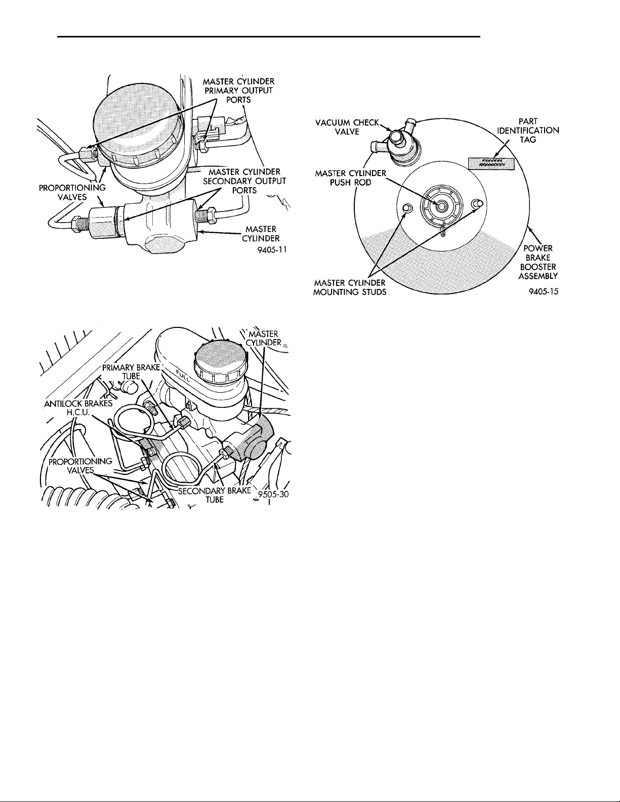
On Non-ABS master cylinders, the primary outlet
ports (Fig. 14) supply hydraulic pressure to the left
front and right rear brakes. The secondary outlet
ports (Fig. 14) supply hydraulic pressure to the right
front and left rear brakes.
On ABS master cylinders, the primary outlet port
(Fig. 15) supplies hydraulic pressure to the right
front and left rear brakes. The secondary outlet port
Page 7
MASTER CYLINDER PRI-MARY OUTPUT PORTSPROPORTIONINGVALVES MASTER CYLINDER SEC-ONDARY OUTPUT PORTSMASTERCYLINDER
ANTILOCKBRAKESH.C.U.PRIMARY BRAKE TUBEMASTER CYLINDERPROPOR-TIONINGVALVESSECONDARYBRAKE TUBE
VACUUM CHECKVALVE PART IDENTIFICA-TION TAGPOWERBRAKEBOOSTERASSEMBLYMASTER CYLINDER MOUNT-ING STUDSMASTER CYLINDER PUSHROD
PL BRAKES 5 - 7
DESCRIPTION AND OPERATION (Continued)
unit if it is found to be faulty in any way. The power
booster vacuum check valve is not repairable but
can be replaced as an assembly.
Fig. 14 Non-ABS Master Cylinder Primary And
Secondary Ports
(Fig. 15) supplies hydraulic pressure to the left front
and right rear brakes.
Fig. 15 ABS Master Cylinder Primary And
Secondary Ports
VACUUM BOOSTER
All vehicles use a 230 mm single diaphragm power
brake vacuum booster. There are however two different booster designs; one for vehicles equipped with
ABS and one for vehicles without ABS. These two
boosters differ at the interface to the master cylinder.
If the power brake booster requires replacement be
sure it is replaced with the correct part.
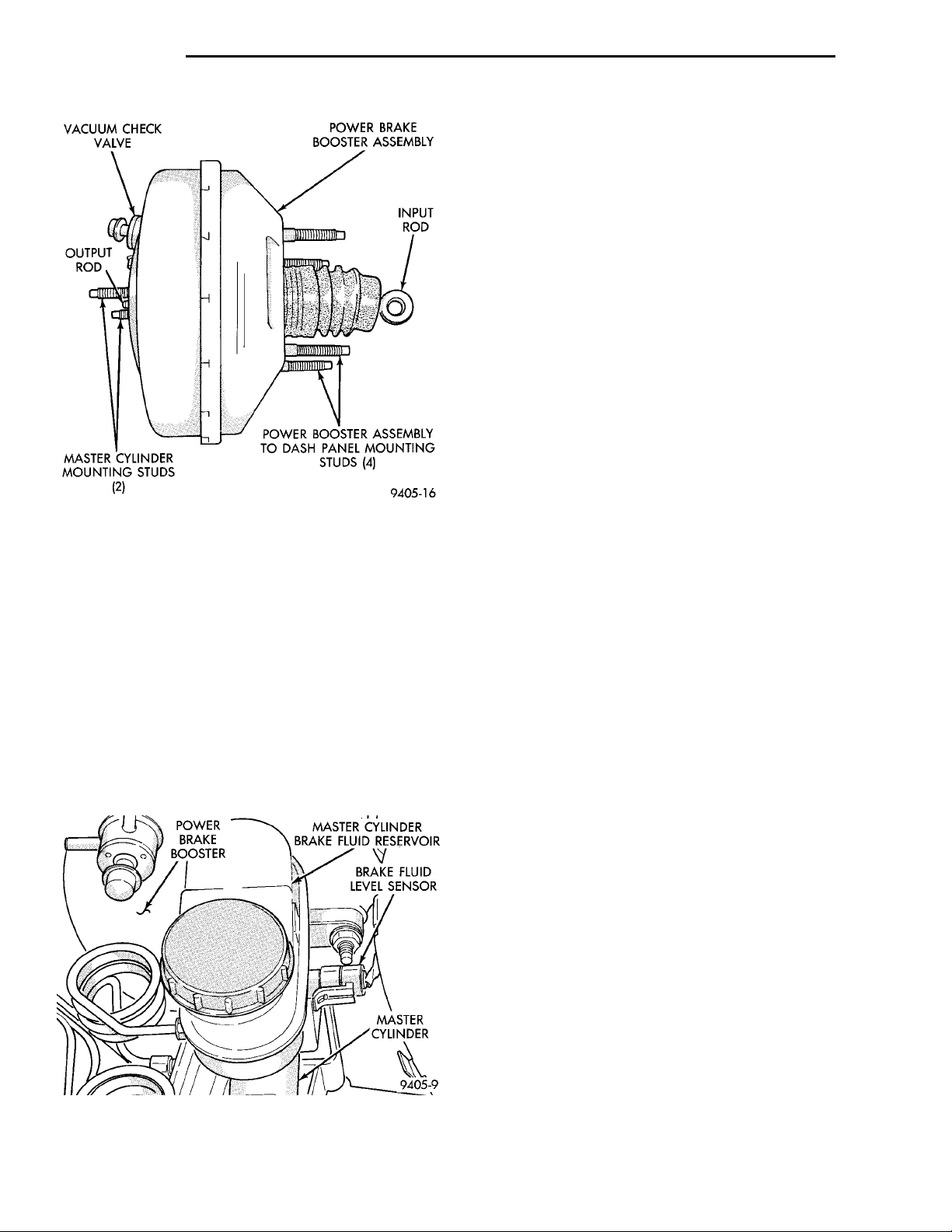
The power brake booster can be identified by the
tag attached to the body of the booster assembly (Fig.
16). This tag contains the following information: The
production part number of the power booster assembly, the date it was built, who manufactured it, and
brake sales code.
NOTE: The power brake booster assembly is not a
repairable part and must be replaced as a complete
Fig. 16 Power Brake Booster Identification
The power brake booster reduces the amount of
force required by the driver to obtain the necessary
hydraulic pressure to stop vehicle.
The power brake booster is vacuum operated. The
vacuum is supplied from the intake manifold on the
engine through the power brake booster check valve
(Fig. 16).
As the brake pedal is depressed, the power booster
input rod moves forward (Fig. 17). This opens and
closes valves in the power booster, allowing atmospheric pressure to enter on one side of a diaphragm.
Engine vacuum is always present on the other side.
This difference in pressure forces the output rod of
the power booster (Fig. 17) out against the primary
piston of the master cylinder. As the pistons in the
master cylinder move forward this creates the
hydraulic pressure in the brake system.
Different engine options available for this vehicle
require that different vacuum hose routings be used.
The power brake vacuum booster assembly mounts
on the engine side of the dash panel. It is connected
to the brake pedal by the input push rod (Fig. 17). A
vacuum line connects the power booster to the intake
manifold. The master cylinder is bolted to the front
of the power brake vacuum booster assembly.
RED BRAKE WARNING LAMP
The red Brake warning lamp is located in the
instrument panel cluster and is used to indicate a
low brake fluid condition or that the parking brake is
applied. In addition, the brake warning lamp is
turned on as a bulb check by the ignition switch
when the ignition switch is placed in the crank position. Problems with this system will generally be of
the type where the warning lamp fails to turn on
when it should, or remains on when it should not.
Page 8
VACUUM CHECK VALVE POWER BRAKE BOOSTERASSEMBLYINPUT RODPOWER BOOSTER ASSEM-BLY TO DASH PANELMOUNTING STUDS (4)MASTER CYLINDERMOUNTING STUDS (2)OUTPUTROD
POWER BRAKEBOOSTER MASTER CYLINDER BRAKEFLUID RESERVOIRBRAKE FLUIDLEVEL SENSORMASTER CYLINDER
5 - 8 BRAKES PL
DESCRIPTION AND OPERATION (Continued)
As the fluid drops below the minimum level, the
fluid level sensor closes the brake warning light circuit. This will turn on the red brake warning light.
At this time, master cylinder fluid reservoir should
be checked and filled to the full mark with DOT 3
brake fluid. If brake fluid level has dropped in
master cylinder fluid reservoir, the entire
brake hydraulic system should be checked for
evidence of a leak.
STOP LAMP SWITCH
The stop lamp switch controls operation of the
vehicles stop lamps. Also, if the vehicle is equipped
with speed control, the stop lamp switch will deactivate speed control when the brake pedal is
depressed.
The stop lamp switch controls operation of the
right and left tail, stop and turn signal lamp and
CHMSL lamp, by supplying battery current to these
lamps.
The stop lamp switch controls the lamp operation
by opening and closing the electrical circuit to the
Fig. 17 Power Brake Booster Assembly
The warning lamp bulb is supplied a 12 volt ignition feed anytime the ignition switch is on. The bulb
is then illuminated by completing the ground circuit
either through the park brake switch, the fluid level
sensor in the master cylinder reservoir, or the ignition switch in the crank position.
The Brake Fluid Level sensor is located in the
brake fluid reservoir of the master cylinder assembly
(Fig. 18). The purpose of the sensor is to provide the
driver with an early warning that the brake fluid
level in the master cylinder reservoir has dropped to
below normal. This may indicate an abnormal loss of
brake fluid in the master cylinder fluid reservoir
resulting from a leak in the hydraulic system.
stop lamps.
REAR WHEEL HUB AND BEARING ASSEMBLY
All vehicles are equipped with permanently lubricated and sealed for life rear wheel bearings. There
is no periodic lubrication or maintenance recommended for these units. However, if servicing of a
rear wheel bearing is required, refer to procedures in
the diagnosis and testing section and the removal
and installation section in this group of the service
manual for the inspection and replacement of the
rear wheel bearing.
Fig. 18 Master Cylinder Fluid Level Sensor
Page 9
PL BRAKES 5 - 9
DIAGNOSIS AND TESTING
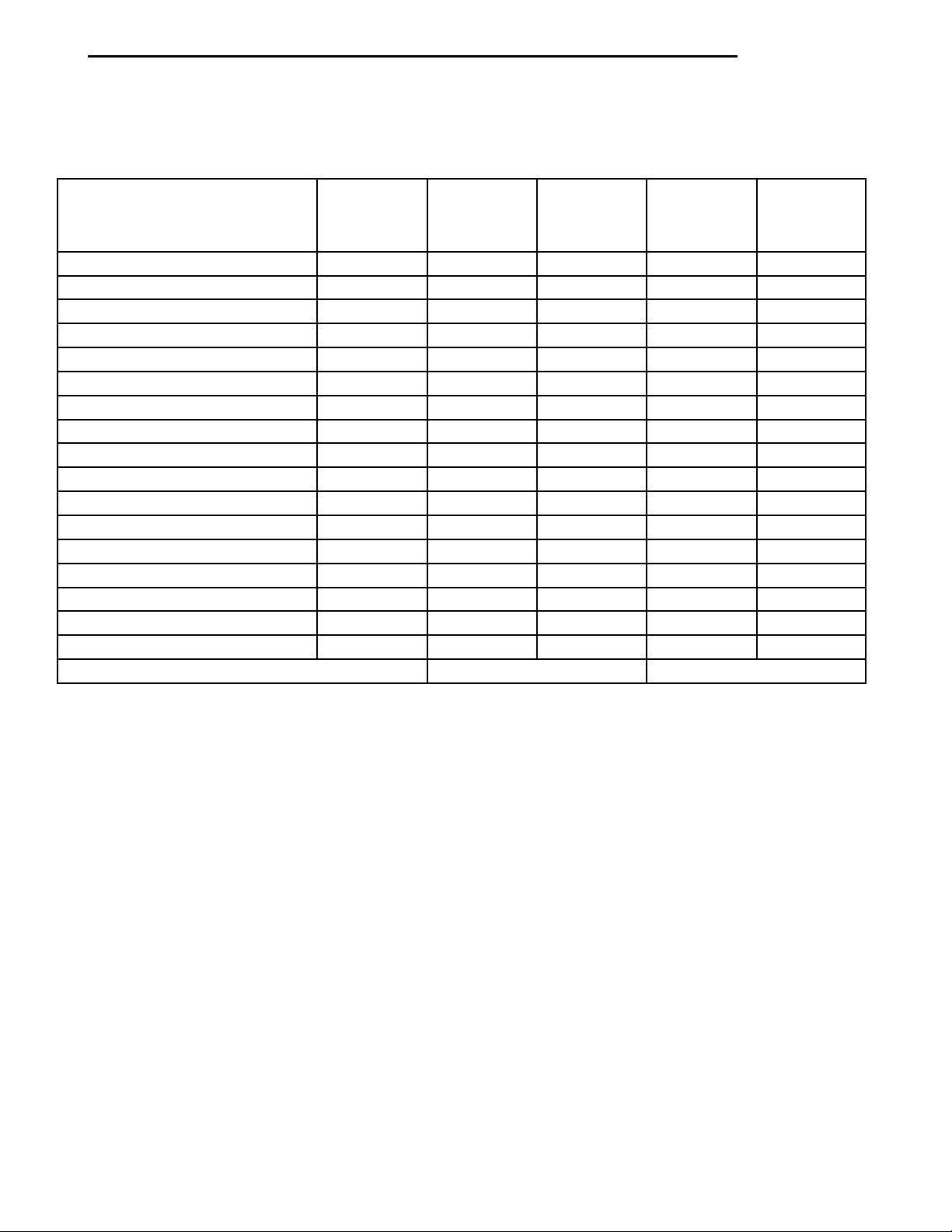
BRAKE SYSTEM BASIC DIAGNOSIS GUIDE
CHART 1
SYMPTOM
Brake Warning Light On X NO NO
Excessive Pedal Travel 6 X NO O
Pedal Goes To The Floor 6 X
Stop Light On Without Brakes 3
All Brakes Drag 5
Rear Brakes Drag 2 NO NO
Grabby Brakes O X
Spongy Brake Pedal X NO
Premature Rear Brake Lockup 4 NO NO O
Excessive Pedal Effort 1 O
Rough Engine Idle NO O
Brake Chatter (Rough) NO NO X
Surge During Braking NO NO X
Noise During Braking NO NO X
Rattle Or Clunking Noise NO NO X
Pedal Pulsates During Braking NO NO X
Pull To Right Or Left NO NO X
No: Not A Possible Cause X: Most Likely Cause O: Possible Cause
MISC.
COND.
CHART 2
WARNING
LIGHT
CHART 3
POWER
BRAKES
CHART 4
BRAKE
NOISE
CHART 5
WHEEL
BRAKES
Page 10
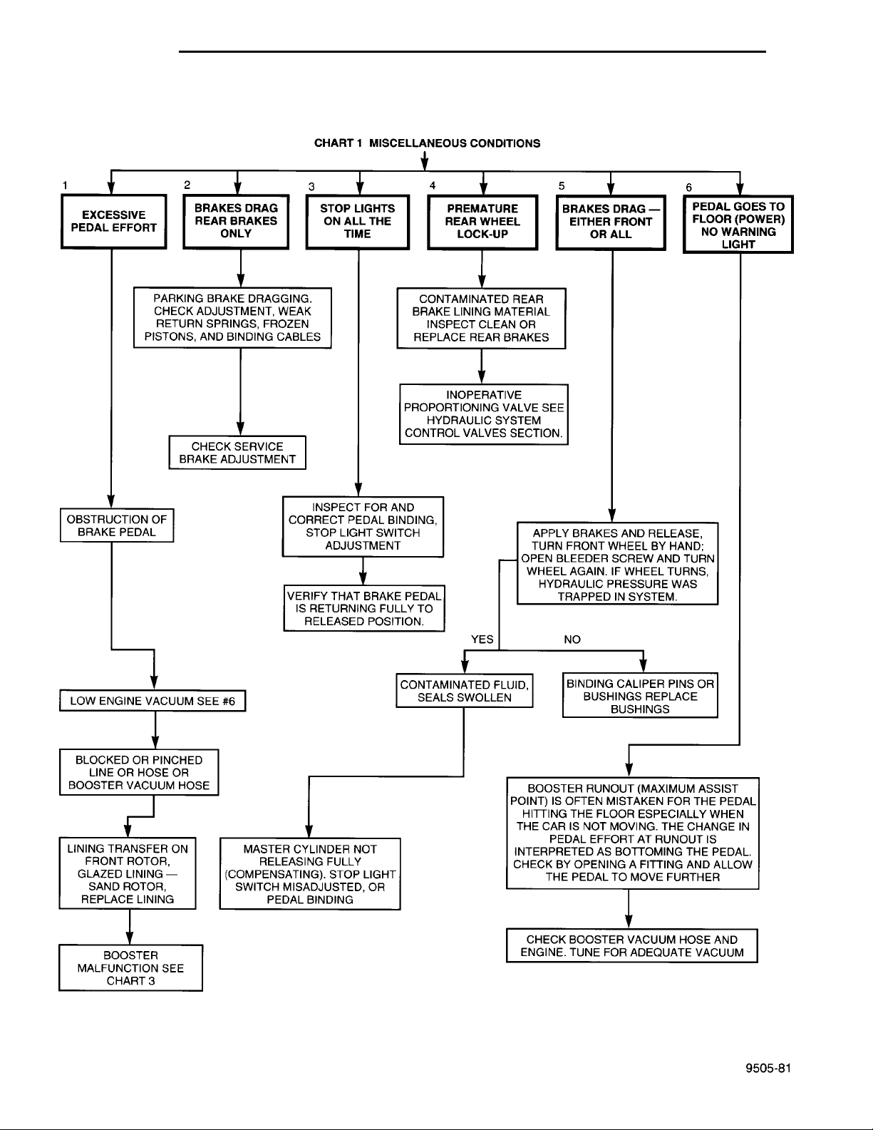
EXCESSIVE PEDALEFFORT BRAKES DRAGREAR BRAKESONLY STOP LIGHTS ON ALLTHE TIME PREMATURE REARWHEEL LOCK-UP BRAKES DRAG —EITHER FRONT ORALL PEDAL GOES TOFLOOR (POWER)NO WARNING LIGHTPARKING BRAKE DRAGGING. CHECKADJUSTMENT, WEAK RETURN SPRINGS,FROZEN PISTONS, AND BINDINGCABLES CONTAMINATED REAR BRAKE LIN-ING MATERIAL INSPECT CLEAN ORREPLACE REAR BRAKESINOPERATIVE PROPORTIONINGVALVE SEE HYDRAULIC SYSTEMCONTROL VALVES SECTION.CHECK SERVICE BRAKEADJUSTMENTOBSTRUCTION OF BRAKEPEDALINSPECT FOR AND COR-RECT PEDAL BINDING,STOP LIGHT SWITCHADJUSTMENTVERIFY THAT BRAKE PEDALIS RETURNING FULLY TORELEASED POSITION.APPLY BRAKES ANDRELEASE, TURN FRONTWHEEL BY HAND; OPENBLEEDER SCREW ANDTURN WHEEL AGAIN. IFWHEEL TURNS, HYDRAULICPRESSURE WAS TRAPPEDIN SYSTEM.YESNOLOW ENGINE VACUUM SEE#6CONTAMINATED FLUID,SEALS SWOLLENBINDING CALIPER PINS ORBUSHINGS REPLACE BUSH-INGSBLOCKED OR PINCHED LINEOR HOSE OR BOOSTERVACUUM HOSELINING TRANSFER ONFRONT ROTOR, GLAZEDLINING — SAND ROTOR,REPLACE LININGMASTER CYLINDER NOTRELEASING FULLY (COM-PENSATING). STOP LIGHTSWITCH MISADJUSTED, ORPEDAL BINDINGBOOSTER RUNOUT (MAXI-MUM ASSIST POINT) ISOFTEN MISTAKEN FOR THEPEDAL HITTING THE FLOORESPECIALLY WHEN THECAR IS NOT MOVING. THECHANGE IN PEDAL EFFORTAT RUNOUT IS INTER-PRETED AS BOTTOMINGTHE PEDAL. CHECK BYOPENING A FITTING ANDALLOW THE PEDAL TOMOVE FURTHERCHECK BOOSTER VACUUMHOSE AND ENGINE. TUNEFOR ADEQUATE VACUUMBOOSTER MALFUNCTIONSEE CHART 3CHART 1 MISCELLANEOUSCONDITIONS
5 - 10 BRAKES PL
DIAGNOSIS AND TESTING (Continued)
BRAKE SYSTEM DIAGNOSIS CHARTS
MISCELLANEOUS BRAKE SYSTEM CONDITIONS
Page 11
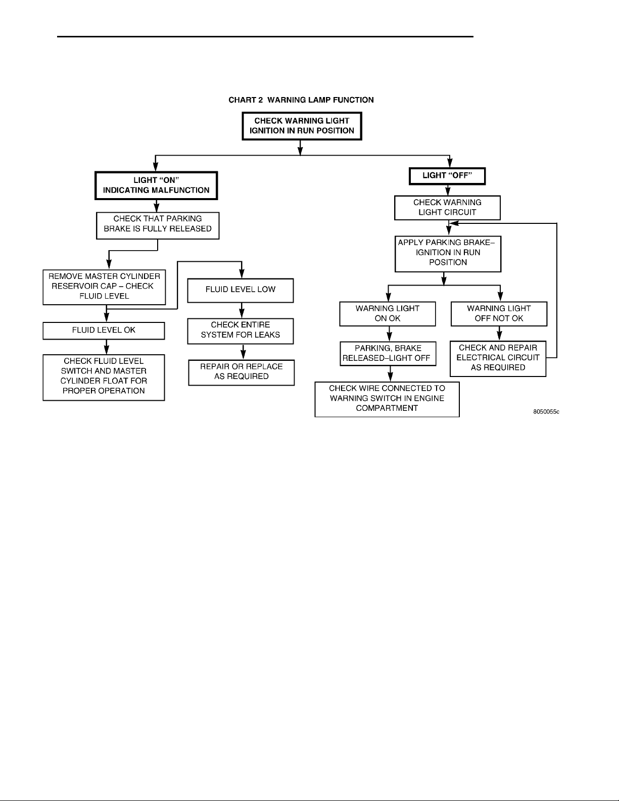
CHART 2 WARNING LAMPFUNCTIONCHECK WARNING LIGHT IGNITIONIN RUN POSITIONLIGHT “ON” INDICATINGMALFUNCTIONCHECK THAT PARKINGBRAKE IS FULLY RELEASEDREMOVE MASTER CYLIN-DER RESERVOIR CAP —CHECK FLUID LEVELFLUID LEVEL OKCHECK FLUID LEVEL SWITCH ANDMASTER CYLINDER FLOAT FORPROPER OPERATION FLUID LEVEL LOWCHECK ENTIRE SYSTEMFOR LEAKSREPAIR OR REPLACE ASREQUIRED LIGHT “OFF”CHECK WARNING LIGHTCIRCUITAPPLY PARKING BRAKE — IGNI-TION IN RUN POSITIONWARNING LIGHT ON OKPARKING, BRAKERELEASED — LIGHT OFFCHECK WIRE CONNECTEDTO WARNING SWITCH INENGINE COMPARTMENT WARNING LIGHT OFF NOTOKCHECK AND REPAIR ELEC-TRICAL CIRCUIT ASREQUIRED
PL BRAKES 5 - 11
DIAGNOSIS AND TESTING (Continued)
RED BRAKE WARNING LAMP FUNCTION
Page 12
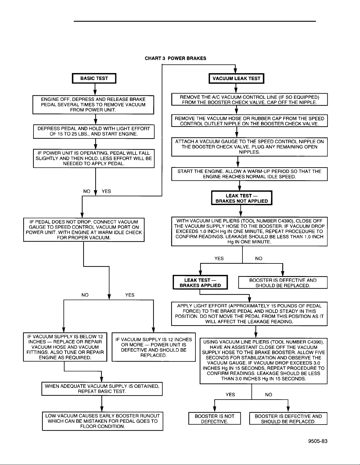
CHART 3 POWER BRAKESBASIC TEST VACUUM LEAK TESTENGINE OFF. DEPRESS AND RELEASE BRAKE PEDAL SEVERALTIMES TO REMOVE VACUUM FROM POWER UNIT. REMOVE THE A/C VACUUM CONTROL LINE (IF SO EQUIPPED) FROM THE BOOSTERCHECK VALVE. CAP OFF THE NIPPLE.DEPRESS PEDAL AND HOLD WITH LIGHT EFFORT OF 15 TO 25LBS., AND START ENGINE. ATTACH A VACUUM GAUGE TO THE SPEED CONTROL NIPPLE ON THE BOOSTERCHECK VALVE. PLUG ANY REMAINING OPEN NIPPLES.IF POWER UNIT IS OPERATING, PEDAL WILL FALL SLIGHTLY ANDTHEN HOLD. LESS EFFORT WILL BE NEEDED TO APPLY PEDAL. START THE ENGINE. ALLOW A WARM-UP PERIOD SO THAT THE ENGINE REACHESNORMAL IDLE SPEED.NO YES LEAK TEST — BRAKES NOTAPPLIEDIF PEDAL DOES NOT DROP, CONNECT VACUUM GAUGE TOSPEED CONTROL VACUUM PORT ON POWER UNIT. WITH ENGINEAT WARM IDLE CHECK FOR PROPER VACUUM. WITH VACUUM LIN PLIERS (TOOL NUMBER C4390), CLOSE OFF THE VACUUM SUPPLYHOSE TO THE BOOSTER. IF VACUUM DROP EXCEEDS 1.0 INCH Hg IN ONE MINUTE,REPEAT PROCEDURE TO CONFIRM READINGS. LEAKAGE SHOULD BE LESS THAN 1.0INCH Hg IN ONE MINUTE.YES NOLEAK TEST — BRAKESAPPLIED BOOSTER IS DEFECTIVE AND SHOULD BEREPLACED.NO YES APPLY LIGHT EFFORT (APPROXIMATELY 15 POUNDS OF PEDAL FORCE) TO THEBRAKE PEDAL AND HOLD STEADY IN THIS POSITION. DO NOT MOVE THE PEDALFROM THIS POSITION AS IT WILL AFFECT THE LEAKAGE READING.IF VACUUM SUPPLY IS BELOW 12 INCHES —REPLACE OR REPAIR VACUUM HOSE ANDVACUUM FITTINGS. ALSO TUNE OR REPAIRENGINE AS REQUIRED. IF VACUUM SUPPLY IS 12INCHES OR MORE —POWER UNIT IS DEFECTIVEAND SHOULD BEREPLACED. USING VACUUM LINE PLIERS (TOOL NUMBER C4390), HAVE AN ASSIS-TANT CLOSE OFF THE VACUUM SUPPLY HOSE TO THE BRAKEBOOSTER. ALLOW FIVE SECONDS FOR STABILIZATION AND OBSERVETHE VACUUM GAUGE. IF VACUUM DROP EXCEEDS 3.0 INCHES Hg IN15 SECONDS, REPEAT PROCEDURE TO CONFIRM READINGS. LEAK-AGE SHOULD BE LESS THAN 3.0 INCHES Hg IN 15 SECONDS.WHEN ADEQUATE VACUUM SUPPLY IS OBTAINED, REPEAT BASICTEST. YES NOLOW VACUUM CAUSES EARLY BOOSTER RUNOUT WHICH CAN BEMISTAKEN FOR PEDAL GOES TO FLOOR CONDITION. BOOSTER IS NOT DEFEC-TIVE. BOOSTER IS DEFECTIVE AND SHOULDBE REPLACED.
REMOVE THE VACUUM HOSE OR RUBBER CAP FROM THE SPEED CONTROL OUTLET NIPPLE ON THE
BOOSTER CHECK VALVE.
5 - 12 BRAKES PL
DIAGNOSIS AND TESTING (Continued)
POWER BRAKE SYSTEM DIAGNOSTICS
Page 13
DETERMINE NOISE LOCA-TION FRONT OR REARDISC BRAKES FRONTAND REARHIGH PITCH SQUEAK ATLOW SPEED, LIGHT PEDALREPLACE BRAKE PADS RATTLE ORCLUNKINGBROKEN OR MISS-ING ANTI-RATTLESPRING OR CLIPPINS LOOSE SCRAPING (METAL TOMETAL)INSPECT FOR INTER-FERENCE OR FOREIGNOBJECTSREPLACE WORN OUTLININGS CHIRPCHECKROTORRUNOUTGREASERAILS DRUM BRAKES
LUBRICATE BRAKE SHOE SUPPORT PLAT-FORMS AND BRAKE SHOE TO ABUTMENTPOINT.REPLACE REAR BRAKE SHOESCHIRPLUBRICATE SUP-PORT PLATE PLAT-FORMSCHECK FOR CORRECTWHEEL CYLINDER ALIGN-MENT CLUNKINSPECT FORTHREADEDDRUMSSCRAPING/WHIRRINGINSPECT SPEED SENSORAND TONE WHEEL AT SUS-PECT LOCATION (ABS ONLY)
HOWL/MOAN
PL BRAKES 5 - 13
DIAGNOSIS AND TESTING (Continued)
BRAKE NOISE
CHART 5 WHEEL BRAKES ROAD TEST CARPULL TO RIGHT OR LEFTCHECK FOR FROZEN PISTONS, CONTAMI-NATED BRAKE SHOES/PADS, PINCHED LINES,LEAKING SEALS, PLUGGED BANJO BOLTREFER TO GROUP 2 — SUS-PENSIONEXCESSIVE PEDAL TRAVELDEFECTIVE AUTOMATIC ADJUSTERCHECK
MASTER CYLINDER INTERNAL LEAKREPLACE MASTER CYLINDER. EXCESSIVE PEDAL EFFORTINSPECT FRONT AND REARBRAKES FOR FROZEN PIS-TONS, CONTAMINATED LIN-ING, GLAZED LINING.LOW ENGINE VACUUMSEE CHART 3 EARLY REAR LOCK-UPCONTAMINATED REARBRAKE LINING MATERIALINSPECT CLEAN ORREPLACE REAR BRAKESINOPERATIVE PROPOR-TIONING VALVE SEEHYDRAULIC SYSTEM CON-TROL VALVES SECTION.NO VIBRATION OR PULSINGINSPECT FRONT BRAKESFOR DISC RUNOUT ORTHICKNESS VARIATION PEDAL PULSES, CARSURGES DURING BRAKING,BRAKE CHATTERAPPLY PARKING BRAKESONLYSURGING OR PULSINGSTILL PRESENTINSPECT REAR BRAKEDRUMS FOR OUT OFROUND AND OVALITY ORREAR DISC FOR THICKNESSVARIATIONGRABBY BRAKESCONTAMINATED LINING
AIR IN BRAKE HYDRAULIC SYSTEM — BLEED BRAKE
LEAK IN BRAKE HYDRAULIC SYSTEM — LOOK FOR WET
HYDRAULIC SYSTEM
AREAS AND REPAIR
VEHICLE ROAD TEST
Page 14
5 - 14 BRAKES PL
DIAGNOSIS AND TESTING (Continued)
DRUM BRAKE AUTOMATIC ADJUSTER
Place the vehicle on a hoist with a helper in the
driver’s seat to apply the brakes. Remove the access
plug from the rear adjustment slot in each brake
support plate to provide access to the adjuster star
wheel. Then, to eliminate the possibility of maximum
adjustment, back the star wheel off approximately 10
notches. It will be necessary to hold the adjuster
lever away from the star wheel to permit this adjustment.
Apply the brake pedal. This application of force
will cause the brake shoes to leave the anchor. Upon
application of the brake pedal, the lever should move
downward, turning the star wheel. Thus, a definite
rotation of the adjuster star wheel can be observed if
the automatic adjuster is working properly. If one or
more adjusters do not function properly, the respective drum must be removed for adjuster servicing.
ROTOR THICKNESS AND RUNOUT
Any servicing of the rotor requires extreme care to
maintain the rotor within service tolerances to
ensure proper brake action.
Before refinishing or refacing a rotor, the disc
should be checked and inspected for the following
conditions:
Braking surface scoring, rust, impregnation of lining material and worn ridges.
Excessive lateral runout or wobble.
Thickness variation (Parallelism).
Dishing or distortion (Flatness).
If a vehicle has not been driven for a period of
time, the rotor surface will rust in the area not covered by the brake lining and cause noise and chatter
when the brakes are applied.
Excessive wear and scoring of the rotor can cause
temporary improper lining contact if ridges are not
removed before installation of new brake pad assemblies.
Some discoloration or wear of the rotor surface is
normal and does not require resurfacing when linings are replaced.
Excessive runout or wobble in a rotor can increase
pedal travel due to piston knock back. This will
increase guide pin sleeve wear due to tendency of caliper to follow rotor wobble.
Thickness variation in a rotor can also result in
pedal pulsation, chatter and surge due to variation in
brake output. This can also be caused by excessive
runout in rotor or hub.
Dishing or distortion can be caused by extreme
heat and abuse of the brakes.
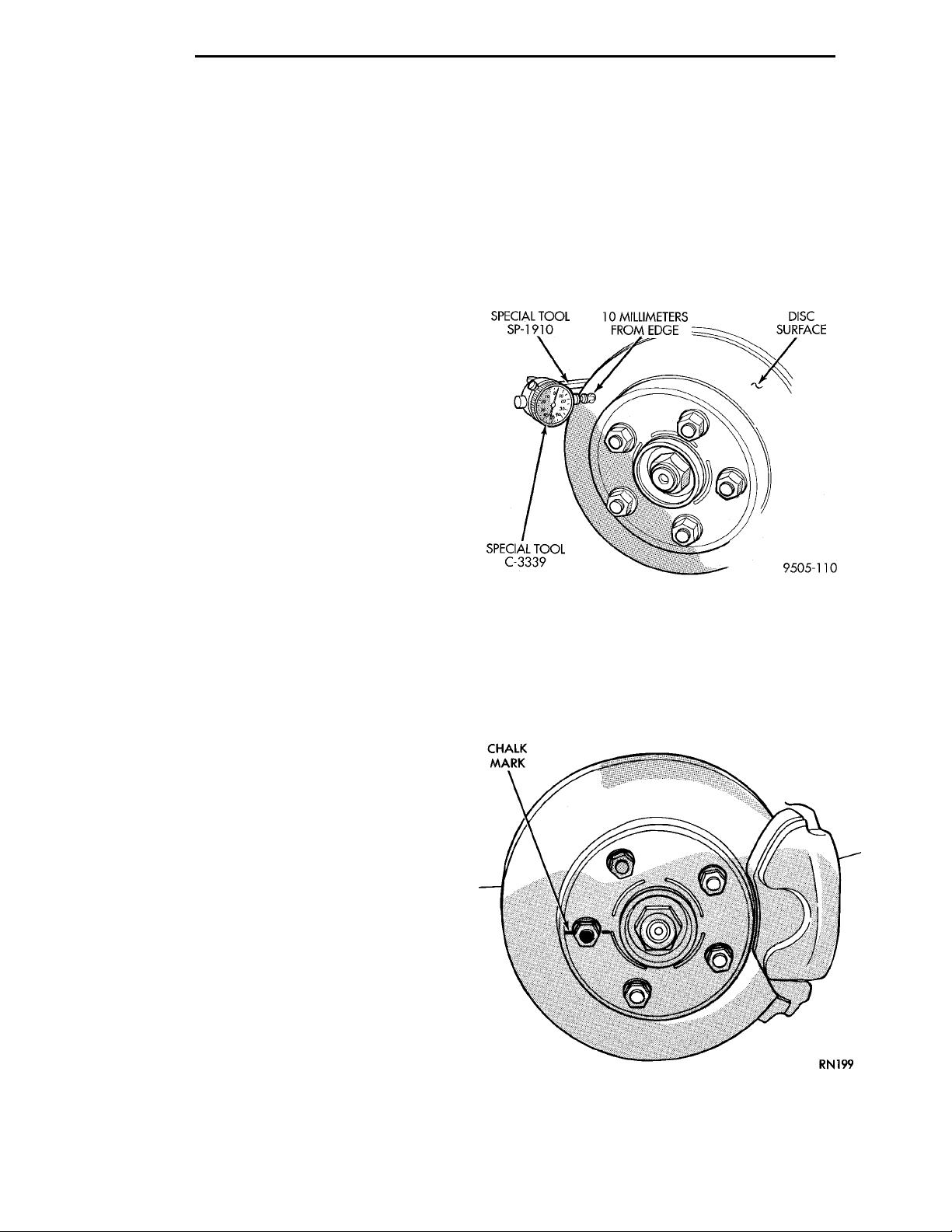
ROTOR RUNOUT AND THICKNESS VARIATION
On vehicle rotor runout is the combination of the
individual runout of the hub face and the runout of
the rotor. (The hub and rotor runouts are separable).
To measure runout on the vehicle, remove the wheel
and reinstall the lug nuts tightening the rotor to the
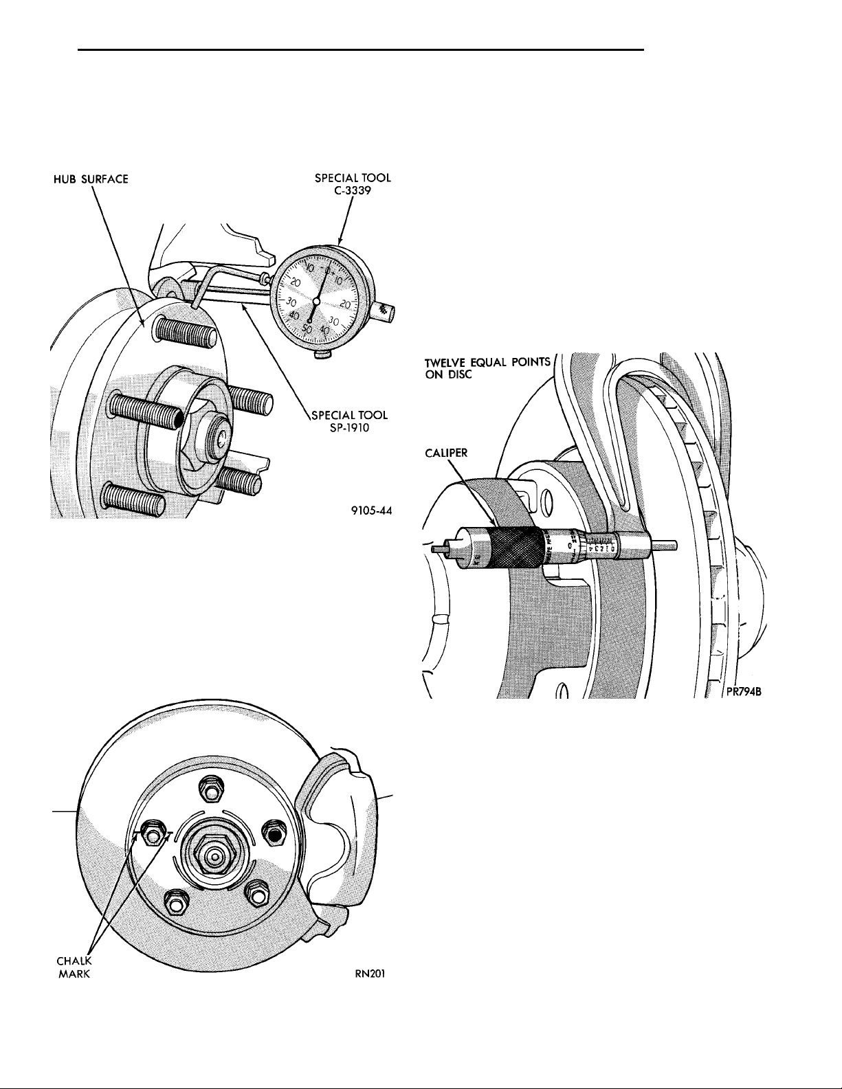
hub. Mount Dial Indicator, Special Tool C-3339 with
Mounting Adaptor, Special Tool SP- 1910 on steering
arm. Dial indicator plunger should contact braking
surface of rotor approximately one inch from edge of
rotor (Fig. 19). Check lateral runout (both sides of
rotor) runout should not exceed 0.13 mm (0.005
inch).
Fig. 19 Checking Rotor For Runout
If runout is in excess of the specification, check the
lateral runout of the hub face. Before removing rotor
from hub, make a chalk mark across both the rotor
and one wheel stud on the high side of runout so
you’ll know exactly how the rotor and hub was originally mounted (Fig. 20). Remove rotor from hub.
Fig. 20 Marking Rotor and Wheel Stud
Install Dial Indicator, Special Tool C-3339 and
Mounting Adaptor, Special Tool SP-1910 on steering
knuckle. Position stem so it contacts hub face near
Page 15
PL BRAKES 5 - 15
DIAGNOSIS AND TESTING (Continued)
outer diameter. Care must be taken to position stem
outside the stud circle but inside the chamfer on the
hub rim (Fig. 21). Clean hub surface before
checking.
If runout is not within specifications. Install a new
rotor or reface rotor, being careful to remove as little
as possible from each side of rotor. Remove equal
amounts from each side of rotor. Do not reduce thickness below minimum thickness cast into the un-machined surface of the rotor.
Thickness variation measurements of rotor should
be made in conjunction with runout. Measure thickness of rotor at 12 equal points with a micrometer at
a radius approximately 25 mm (1 inch) from edge of
rotor (Fig. 23). If thickness measurements vary by
more than 0.013 mm (0.0005 inch) rotor should be
removed and resurfaced, or a new rotor installed. If
cracks or burned spots are evident, rotor must be
replaced.
Fig. 21 Checking Hub for Runout
Runout should not exceed 0.08 mm (0.003 inch). If
runout exceeds this specification, hub must be
replaced. See Suspension Group 2. If hub runout
CHALK MARK
does not exceed this specification, install rotor on hub
with chalk marks two wheel studs apart (Fig. 22).
Tighten nuts in the proper sequence and torque to
specifications. Finally, check runout of rotor to see if
runout is now within specifications.
Fig. 22 Index Rotor And Wheel Stud
Fig. 23 Checking Rotor For Thickness
Light scoring and/or wear is acceptable. If heavy
scoring or warping is evident, the rotor must be
machined or replaced. See Brake Rotor Machining in
the Service Procedures Section in this group of the
service manual. Refer to front or rear brake rotor in
the Removal And Installation section in this group of
the service manual for the required brake rotor
replacement procedure.
PROPORTIONING VALVES
PROPORTIONING VALVE TESTING SPECIAL TOOLS
The in-line proportioning valves used on this vehicle require special pressure fittings to test the proportioning valves for proper proportioning valve
function. The pressure fittings are installed before
and after the proportioning valve being tested to ver-
Page 16
SPECIAL TOOL 6805PROPORTIONING VALVE TOMASTER CYLINDER OR HCUFITTINGPROPORTIONING VALVE TOMASTER CYLINDER OR HCUFITTINGBRAKE TUBE TOPROPORTIONINGVALVE FITTINGS
SPECIAL TOOL C-4007–A
AIR CLEANERAIR INLET MASTER CYLINDER
LEFT REAR BRAKE PROPOR-TIONING VALVE
RIGHT REAR BRAKE PROPOR-
TIONING VALVE
LEFT FRONT BRAKE
RIGHT FRONT
BRAKE TUBE
TUBE
5 - 16 BRAKES PL
DIAGNOSIS AND TESTING (Continued)
ify proportioning valve is maintaining the required
hydraulic pressure to the rear wheel brake which it
controls.
If a condition of premature rear wheel skid occurs
on a vehicle, the proportioning valve should always
be tested prior to it being replaced. This is due to the
fact that there are conditions other then a faulty proportioning valve which can cause a premature rear
wheel skid.
Testing proportioning valve pressures on a vehicle
with or without ABS requires using the same special
tools.
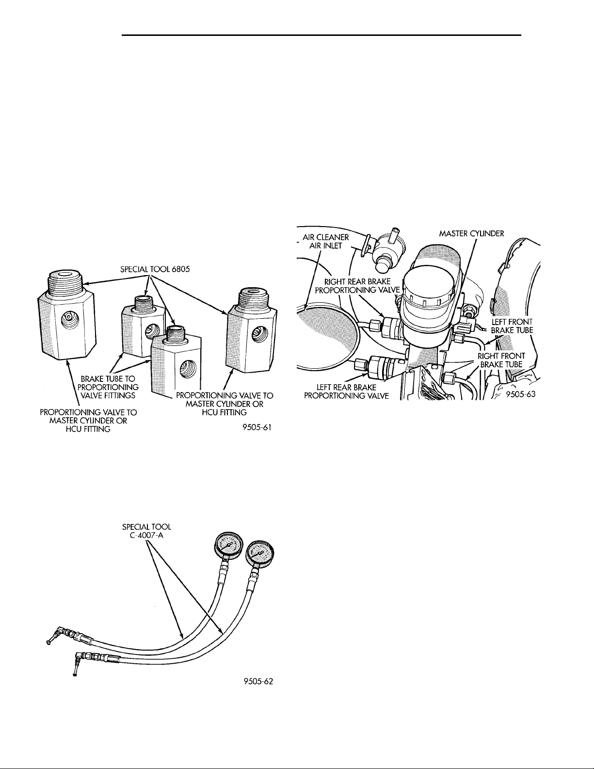
There are 4 Pressure Fittings, Special Tool 6805
(Fig. 24) which are to be used for testing both rear
proportioning valves if mounted at the master cylinder or the HCU.
PROPORTIONING VALVE TESTING NON ABS BRAKE
If premature rear wheel skid occurs on hard brake
application, it could be an indication that a malfunction has occurred with one of the proportioning
valves.
One proportioning valve controls the right rear
brake, and the other proportioning valve controls the
left rear brake (Fig. 26). Therefore, a road test to
determine which rear brake slides first is essential.
Once the wheel which slides first is determined, use
the following procedure to diagnose the proportioning
valve.
Fig. 24 Proportioning Valve Pressure Test Fittings
The pressure gauges used for testing the new inline proportioning valves on both non-ABS and ABS
brakes, is Pressure Gauge Set, Special Tool C-4007-A
currently used for testing the combination valve (Fig.
25).
Fig. 25 Proportioning Valve Pressure Test Gauge
Set
Fig. 26 Non-ABS Brakes Proportioning Valve
Location On Master Cylinder
The test procedure for a premature rear wheel skid
is the same for both rear wheel proportioning valves.
The pressure test fittings used for each proportioning
valve though are different due to proportioning valve
and brake tube nut thread sizes being unique for
each rear wheel. After road testing vehicle to determine which wheel skids first, the proper test fittings
required will have to be determined. Then follow the
procedure below for testing the required proportioning valve.
(1) After road testing vehicle to determine which
rear wheel exhibits premature rear wheel skid, refer
to (Fig. 26) to determine which proportioning valve
needs to be tested.
(2) Remove hydraulic brake tube (Fig. 26) from
proportioning valve controlling the rear wheel of the
vehicle which has premature wheel skid.
(3) Remove proportioning valve from that outlet
port of the master cylinder.
CAUTION: Be sure the pressure test fitting being
installed into master cylinder, has the correct
thread sizes for installation into the master cylinder
and the installation of the proportioning valve.
Page 17
SPECIAL TOOL 6805-1OR 6805-2 MASTERCYL-INDERSPECIAL TOOL 6805-3 OR6805-4PROPORTIONINGVALVE
SPECIAL TOOLC-4007-A BLEED AIR FROM GAUGEHOSES HEREPRESSURE TEST FIT-TINGSPROPOR-TIONING VALVE
PL BRAKES 5 - 17
DIAGNOSIS AND TESTING (Continued)
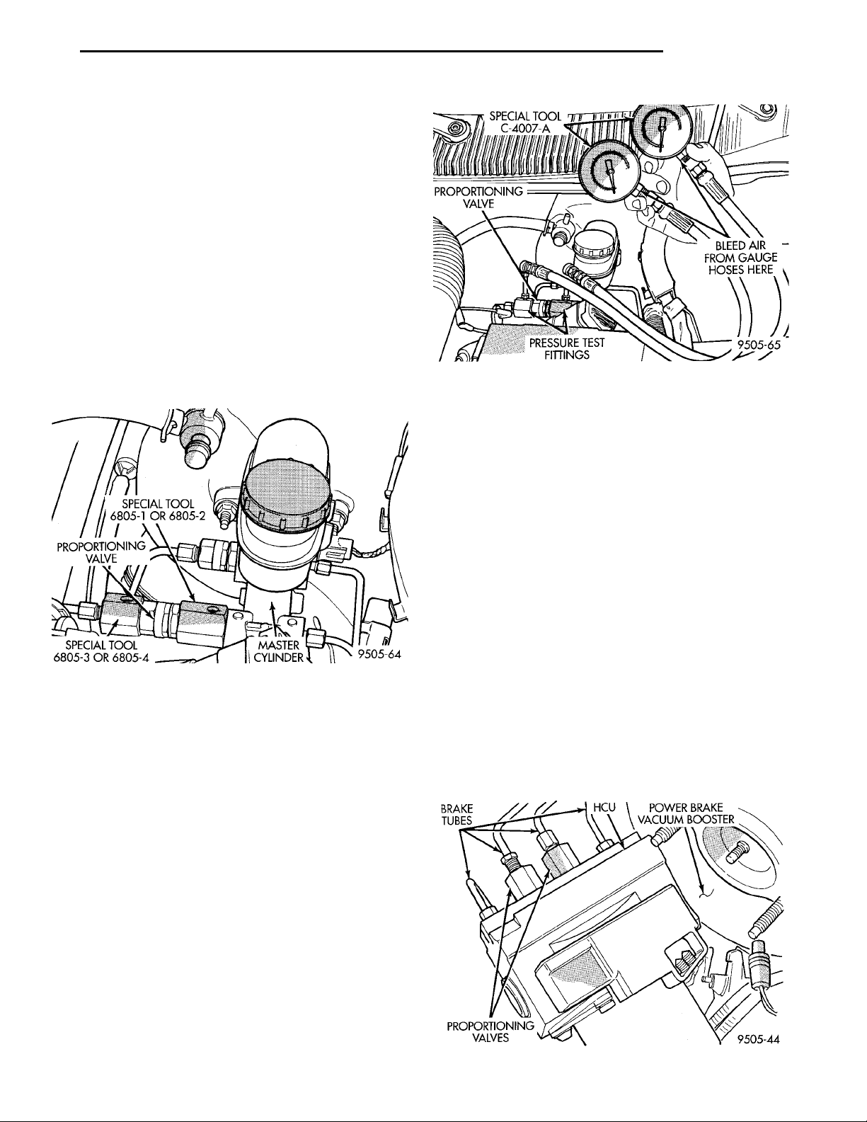
(4) Install Pressure Test Fitting, Special Tool
6805-1 or 6805-2 (Fig. 27) into the outlet port of the
master cylinder, which the proportioning valve was
removed from.
(5) Install proportioning valve into pressure test
fitting installed in master cylinder outlet port (Fig.
27).
CAUTION: Be sure the pressure test fitting being
installed into proportioning valve, has the correct
thread sizes for installation into the proportioning
valve and installation of brake tube fitting.
(6) Install Pressure Test Fitting, Special Tool
6805-3 or 6805-4 (Fig. 27) into the outlet port of the
proportioning valve.
(7) Connect brake hydraulic tube onto the pressure
test fitting that was installed in proportioning valve
(Fig. 27).
Fig. 28 Pressure Gauges Installed On Pressure Test
Fittings
(11) Install proportioning valve in master cylinder
and hand tighten until proportioning is fully
installed and O-ring seal is seated into master cylinder. Then torque proportioning valve to 40 N·m (30
ft. lbs.).
(12) Install brake tube on proportioning valve.
Torque tube nut to 17 N·m (145 in. lbs.) torque.
(13) Bleed the affected brake line. See Bleeding
Brake System in the Service Adjustments section of
the manual for proper bleeding procedure
Fig. 27 Proportioning Valve Installation For
Pressure Testing
(8) Install a Pressure Gauge, Special Tool
C-4007-A into each pressure test fitting (Fig. 28).
Bleed air out of hose from pressure test fitting to
pressure gauge, at pressure gauge to remove all
trapped air. hose.
(9) With the aid of a helper, apply pressure to the
brake pedal until reading on proportioning valve
inlet gauge, is at the pressure shown on the following
chart. Then check the pressure reading on the proportioning valve outlet gauge. If proportioning valve
outlet pressure does not agree with value shown on
the following chart, when inlet pressure shown on
chart is obtained, replace the proportioning valve. If
proportioning valve is within pressure specifications
do not replace proportioning valve.
(10) Check rear wheel brake shoe linings for contamination or for replacement brake shoes not meeting OEM brake lining material specifications. These
conditions can also be a possible cause for a premature rear wheel skid.
PROPORTIONING VALVE TEST WITH ABS BRAKES
If premature rear wheel ABS cycling occurs on a
hard brake application, it could be an indication that
a malfunction has occurred with one of the proportioning valves.
BRAKETUBES HCU POWER BRAKEVACUUM BOOSTERPROPORTIONINGVALVES
One proportioning valve controls the right rear
brake, and the other proportioning valve controls the
left rear brake (Fig. 29). Since ABS cycles both rear
brakes together, both valves must be tested to isolate
the suspect proportioning valve.
Fig. 29 Proportioning Valve Locations On HCU
Page 18
PROPORTIONINGVALVESPECIAL TOOL 6805-3OR 6805-4SPECIAL TOOL 6805-1OR 6805-2HCU
SPECIAL TOOLC-4007-ABLEED AIR FROM BOTH PRES-SURE GAUGES HERE MASTERCYLINDERHCU
5 - 18 BRAKES PL
DIAGNOSIS AND TESTING (Continued)
The test procedure is the same for both rear wheel
proportioning valves. The pressure test fittings used
for each proportioning valve though are different due
to proportioning valve and brake tube nut thread
sizes being unique for each rear wheel. Follow the
procedure below for testing the required proportioning valve.
(1) Road test vehicle to verify premature rear
wheel ABS cycling, refer to (Fig. 29) to determine
which proportioning valve needs to be tested.
(2) Remove hydraulic brake tube (Fig. 29) from
one of the proportioning valves.
(3) Then remove proportioning valve from that
outlet port of the HCU.
CAUTION: Be sure the pressure test fitting being
installed into the HCU, has the correct thread sizes
for installation into the HCU and installation of the
proportioning valve.
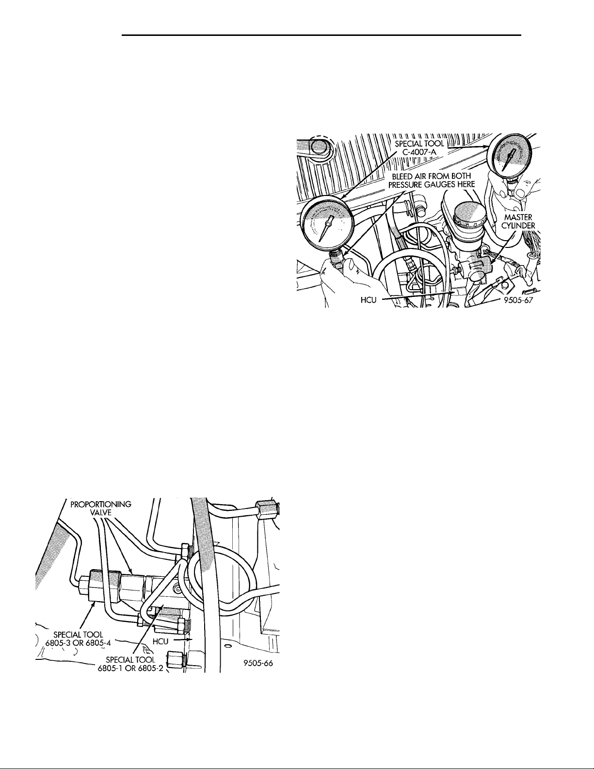
(4) Install Pressure Test Fitting, Special Tool
6805-1 or 6805-2 (Fig. 30) into the outlet port of the
HCU.
(5) Install proportioning valve (Fig. 30) into pressure test fitting installed in the HCU outlet port.
CAUTION: Be sure the pressure test fitting being
installed into proportioning valve, has the correct
thread sizes for installation into the proportioning
valve and installation of brake tube fitting into proportioning valve.
(6) Install Pressure Test Fitting, Special Tool
6805-3 or 6805-4 (Fig. 30) into the outlet of the proportioning valve.
(7) Connect brake tube onto pressure test fitting
installed in proportioning valve (Fig. 30).
(8) Install a Pressure Gauge, Special Tool
C-4007-A into each pressure test fitting (Fig. 31).
Bleed air out of hose from pressure test fitting to
pressure gauge, at pressure gauge to remove all
trapped air.
Fig. 31 Pressure Gauges Installed On Pressure Test
Fittings At HCU
(9) With the aid of a helper, apply pressure to the
brake pedal until reading on proportioning valve
inlet gauge, is at the pressure shown on the following
chart. Then check the pressure reading on the proportioning valve outlet gauge. If proportioning valve
outlet pressure does not agree with value shown on
the following chart, when inlet pressure shown on
chart is obtained, replace the proportioning valve. If
proportioning valve is within pressure specifications
do not replace proportioning valve.
(10) Install proportioning valve in HCU and hand
tighten until proportioning is fully installed and
O-ring seal is seated into HCU. Then torque proportioning valve to 40 N·m (30 ft. lbs.).
(11) Install brake tube on proportioning valve.
Torque tube nut to 17 N·m (145 in. lbs.) torque.
(12) Bleed the affected brake line. See Bleeding
Brake System in the Service Adjustments section of
the manual for proper bleeding procedure.
(13) Repeat steps 2 thru 12 for the second proportioning valve.
(14) Check rear wheel brake shoe linings for contamination or for replacement brake shoes not meeting OEM brake lining material specifications. These
conditions can also be a possible cause for a premature rear wheel skid.
Fig. 30 Proportioning Valve Installation For
Pressure Testing
Page 19
PL BRAKES 5 - 19
DIAGNOSIS AND TESTING (Continued)
BRAKE PROPORTIONING VALVE APPLICATIONS AND PRESSURE SPECIFICATIONS
SALES
CODE
BRA 14” Disc/Drum 400 psi 0.43 Black Band 1000 psi 600-700 psi
BRD 14” Disc/Disc 400 psi 0.34 Bar Code Band 1000 psi 550-650 psi
BRF 14” Disc/Disc W/ABS 400 psi 0.34 Bar Code Band 1000 psi 550-650 psi
BRAKE SYSTEM
TYPE
SPLIT
POINT
SLOPE IDENTIFICATION
INLET
PRESSURE
OUTLET
PRESSURE
BRAKE FLUID CONTAMINATION
Indications of fluid contamination are swollen or
deteriorated rubber parts.
Swollen rubber parts indicate the presence of
petroleum in the brake fluid.
To test for contamination, put a small amount of
drained brake fluid in clear glass jar. If fluid separates into layers, there is mineral oil or other fluid
contamination of the brake fluid.
If brake fluid is contaminated, drain and thoroughly flush system. Replace master cylinder, proportioning valve, caliper seals, wheel cylinder seals,
Antilock Brakes hydraulic unit and all hydraulic
fluid hoses.
RED BRAKE WARNING LAMP TEST
For diagnosis of specific problems with the red
brake warning lamp system, refer to Brake System
Diagnostics Chart 2, located in the Diagnosis And
Testing section in this group of the service manual.
STOP LAMP SWITCH TEST PROCEDURE
The required procedure for testing the stop lamp
switch is covered in Group 8H, Vehicle Speed Control
System in this service manual. The electrical circuit
tests for stop lamps is covered in Group 8W Rear
Lighting in this service manual.
BRAKE BLEEDING
NOTE: For bleeding the ABS hydraulic system, see
Bleeding ABX-4 Brake System in the Service Procedures Section of the ABS Brake Section in this
group of the service manual.
CAUTION: Before removing the master cylinder
cover, wipe it clean to prevent dirt and other foreign
matter from dropping into the master cylinder.
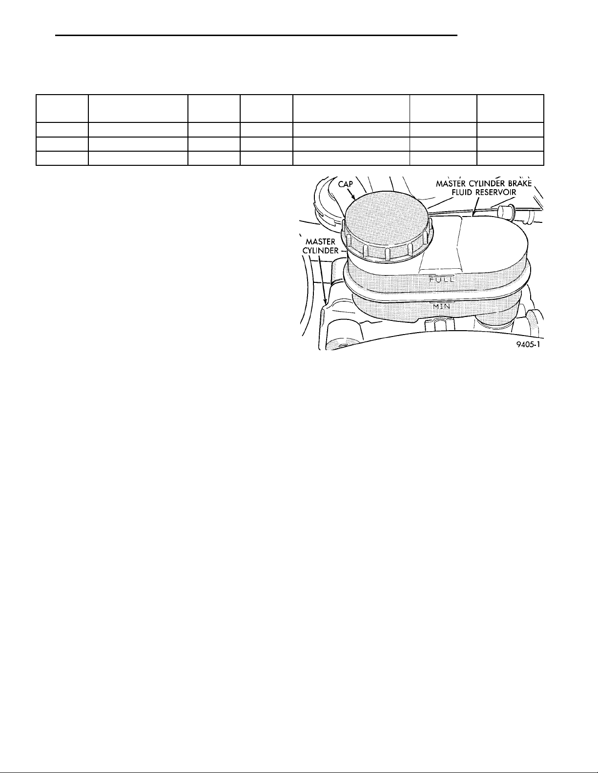
Fig. 32 Master Cylinder Fluid Level
SERVICE PROCEDURES
BRAKE FLUID LEVEL CHECK
Check master cylinder reservoir brake fluid level a
minimum of twice a year.
Master cylinder reservoirs are marked with the
words FULL AND MIN indicating proper range of
the master cylinder fluid level (Fig. 32).
CAUTION: Use only MoparT brake fluid or an
equivalent from a tightly sealed container. Brake
fluid must conform to DOT 3 specifications. Do not
use petroleum-based fluid because seal damage in
the brake system will result.
If necessary, add specified brake fluid bringing
level to the FULL mark on the side of the master
cylinder brake fluid reservoir (Fig. 32).
PRESSURE BLEEDING
CAUTION: Use bleeder tank Special Tool C-3496-B
with required adapter for the master cylinder reservoir to pressurize the hydraulic system for bleeding.
NOTE: Follow pressure bleeder manufacturer’s
instructions for use of pressure bleeding equipment.
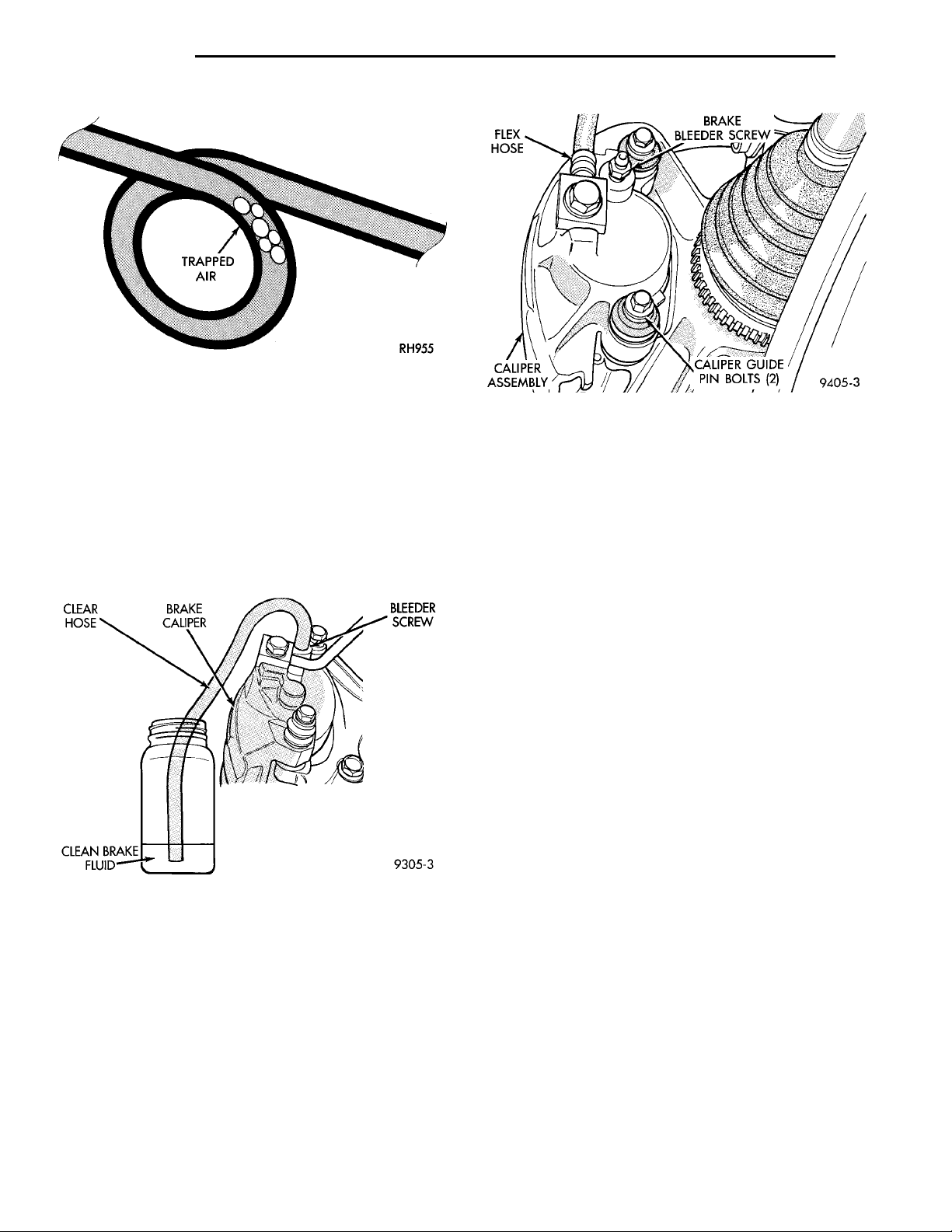
When bleeding the brake system, some air may be
trapped in the brake lines or valves far upstream, as
much as ten feet from the bleeder screw (Fig. 33).
Therefore, it is essential to have a fast flow of a large
volume of brake fluid when bleeding the brakes to
ensure all the air gets out.
The following wheel sequence for bleeding the
brake hydraulic system should be used to ensure
Page 20
FLEX HOSE BRAKE BLEEDERSCREW
CALIPERASSEMBLY
CALIPER GUIDE PIN
BOLTS (2)
5 - 20 BRAKES PL
SERVICE PROCEDURES (Continued)
Fig. 33 Trapped Air in Brake Line
adequate removal of all trapped air from the hydraulic system.
• Left rear wheel
• Right front wheel
• Right rear wheel
• Left front wheel
(1) Attach a clear plastic hose to the bleeder screw
starting at the right rear wheel and feed the hose
into a clear jar containing enough fresh brake fluid
to submerge the end of the hose (Fig. 34).
Fig. 35 Open Bleeder Screw at Least One Full Turn
level in the pressure bleeder. It must stay at the
proper level so air will not be allowed to reenter the
brake system through the master cylinder reservoir.
BLEEDING WITHOUT A PRESSURE BLEEDER
NOTE: Correct bleeding of the brakes hydraulic
system without the use of pressure bleeding equipment will require the aid of a helper.
Fig. 34 Proper Method for Purging Air From Brake
System (Typical)
(2) Open the bleeder screw at least one full turn
or more to obtain an steady stream of brake fluid
(Fig. 35).
(3) After 4 to 8 ounces of fluid has been bled
through the brake and an air-free flow is maintained
in the clear plastic hose and jar, close the bleeder
screw.
(4) Repeat the procedure at all the other remaining bleeder screws. Then check the pedal for travel.
If pedal travel is excessive or has not been improved,
enough fluid has not passed through the system to
expel all the trapped air. Be sure to monitor the fluid
The following wheel sequence for bleeding the
brake hydraulic system should be used to ensure
adequate removal of all trapped air from the hydraulic system.
• Left rear wheel
• Right front wheel
• Right rear wheel
• Left front wheel
(1) Attach a clear plastic hose to the bleeder screw
starting at the right rear wheel and feed the hose
into a clear jar containing enough fresh brake fluid
to submerge the end of the hose (Fig. 34).
(2) Pump the brake pedal three or four times and
hold it down before the bleeder screw is opened.
(3) Open the bleeder screw at least 1 full turn.
When the bleeder screw opens the brake pedal will
drop.
(4) Close the bleeder screw. Release the brake
pedal only after the bleeder screw is closed.
(5) Repeat steps 1 through 3, four or five times at
each bleeder screw. Then check the pedal for travel.
If pedal travel is excessive or has not been improved,
enough fluid has not passed through the system to
expel all the trapped air. Be sure to monitor the fluid
level in the master cylinder reservoir. It must stay at
the proper level so air will not be allowed to re-enter
the brake system.
(6) Test drive vehicle to be sure brakes are operating correctly and that pedal is solid.
Page 21
MASTER CYLINDER FLUIDRESERVOIR MASTERCYLINDERSPECIAL TOOL 6802
MASTER CYLINDERFLUID RESERVOIR MASTERCYLINDERSPECIAL TOOL 6802
BRAKE FLUID RESERVOIRMASTER CYLINDERWOODENDOWEL SPECIAL TOOL 6802
PL BRAKES 5 - 21
SERVICE PROCEDURES (Continued)
MASTER CYLINDER BLEEDING
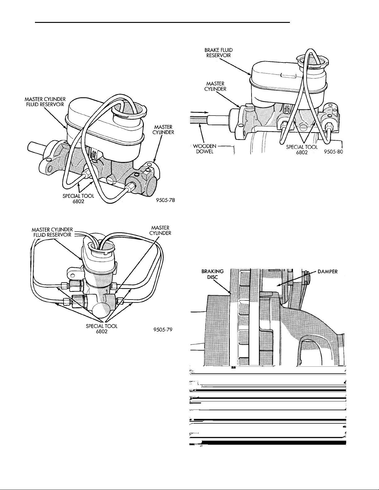
(1) Clamp the master cylinder in a vise. Attach
Bleeding Tubes, Special Tool 6802 to the master cylinder (Fig. 36) and (Fig. 37). Position so outlets of
Bleeding Tubes will be below surface of brake fluid
when reservoir is filled to its proper level.
Fig. 38 Bleeding Master Cylinder
der. But the master cylinder must have been bled
and filled upon installation.
Fig. 36 Bleeding Tubes Attached to ABS Master
Cylinder
Fig. 37 Bleeding Tubes Attached To Non-ABS
Master Cylinder
(2) Fill brake fluid reservoir with brake fluid conforming to DOT 3 specifications such as Mopar or an
Equivalent.
(3) Using a wooden dowel per (Fig. 38). Depress
push rod slowly, and then allow pistons to return to
released position. Repeat several times until all air
bubbles are expelled.
(4) Remove bleeding tubes from master cylinder
outlet ports, plug outlet ports and install fill cap on
reservoir.
(5) Remove master cylinder from vise.
BRAKE ROTOR MACHINING
BRAKE ROTOR MACHINING PROCEDURES
Any servicing of the rotor requires extreme care to
maintain the rotor to within service tolerances to
BRAKINGDISC DAMPERCUTTINGTOOLS
ensure proper brake action.
If the rotor surface is deeply scored or warped, or
there is a complaint of brake roughness or pulsation,
the rotor should be resurfaced, refaced (Fig. 39) or
(Fig. 40) or replaced.
NOTE: Note: It is not necessary to bleed the entire
hydraulic system after replacing the master cylin-
Fig. 39 Refacing Brake Rotor
Page 22
BRAKING DISCGRINDER
ROTOR MINIMUM THICK-NESS MARKINGROTOR
5 - 22 BRAKES PL
SERVICE PROCEDURES (Continued)
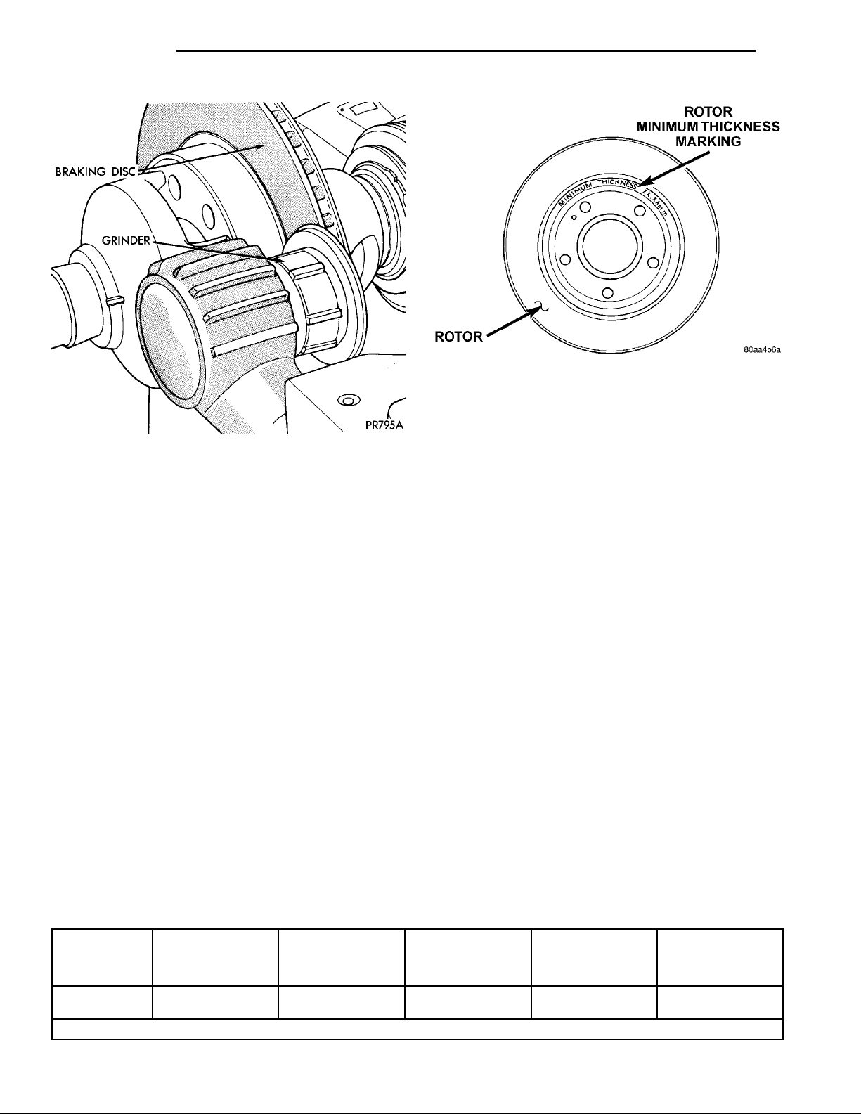
Fig. 41 Minimum Brake Rotor Thickness Markings
(Typical)
REFACING BRAKE ROTOR
Refacing of the rotor is not required each time the
Fig. 40 Resurfacing Brake Rotor (Final Finish)
The following chart shows the location of measure-
ments and specifications when servicing the rotor.
NOTE: All rotors have markings for minimum
allowable thickness cast on an un-machined surface of the rotor (Fig. 41).
This marking includes 0.76 mm (0.030 inch) allowable rotor wear beyond the recommended 0.76 mm
(0.030 inch) of rotor refacing.
The collets, shafts and adapters used on the brake
lathe and the bearing cups in the rotor MUST be
clean and free from any chips or contamination.
When mounting the rotor on the brake lathe, strict
attention to the brake lathe manufacturer’s operating
instructions is required.
If the rotor is not mounted properly, the lateral
runout will be worse after refacing or resurfacing
than before.
brake pads are replaced.
When refacing a rotor the required 0.8 mm (0.003
inch) TIR (Total Indicator Reading) and 0.013 mm
(0.0005 inch) thickness variation limits MUST BE
MAINTAINED. Extreme care in the operation of
rotor turning equipment is required.
The use of a double straddle cutter (Fig. 39) that
machines both sides of the rotor at the same time is
highly recommended.
RESURFACNG BRAKE ROTOR
This operation can be used when rotor surface is
rusty, has lining deposits or excessive lateral runout
or thickness variation is evident.
A sanding rotor attachment will remove surface
contamination without removing much rotor material.
It will generally follow variations in thickness that
are in the rotor.
BRAKE ROTOR REFINISHING LIMITS
BRAKING
ROTOR
All Front Disc
Brakes
* TIR Total Indicator Reading (Measured On Vehicle)
ROTOR
THICKNESS
20.13-19.87 mm
.792 -.782 in.
MINIMUM
ROTOR
THICKNESS
18.4 mm
.724 in.
ROTOR
THICKNESS
VARIATION
0.013 mm
0.0005 in.
ROTOR RUN
OUT*
0.13 mm
0.005 in.
ROTOR MICRO
FINISH
15-80 RMS
Page 23
CENTER CONSOLEASSEMBLY PARK BRAKEHAND LEVERATTACHINGSCREWS PAS-SENGERSEAT
CENTER CON-SOLE LINER CENTER CONSOLE WITHARMREST CENTER CONSOLELIDATTACHINGSCREWS
ATTACHINGSCREWS RADIOCENTER CON-SOLE
PL BRAKES 5 - 23
SERVICE PROCEDURES (Continued)
BRAKE DRUM MACHINING
Measure drum runout and diameter. If not to spec-
HUB/BEARING ASSEMBLYWHEEL MOUNTING STUDSBRAKE DRUM MAXIMUMDIAMETER MARKINGREAR BRAKE DRUM
ification, reface drum. (Runout should not exceed
0.1524 mm or 0.006 inch). The diameter variation
(oval shape) of the drum braking surface must not
exceed either 0.0635 mm (0.0025 inch) in 30° or
0.0889 mm (0.0035 inch) in 360°.
All brake drums are marked with the maximum
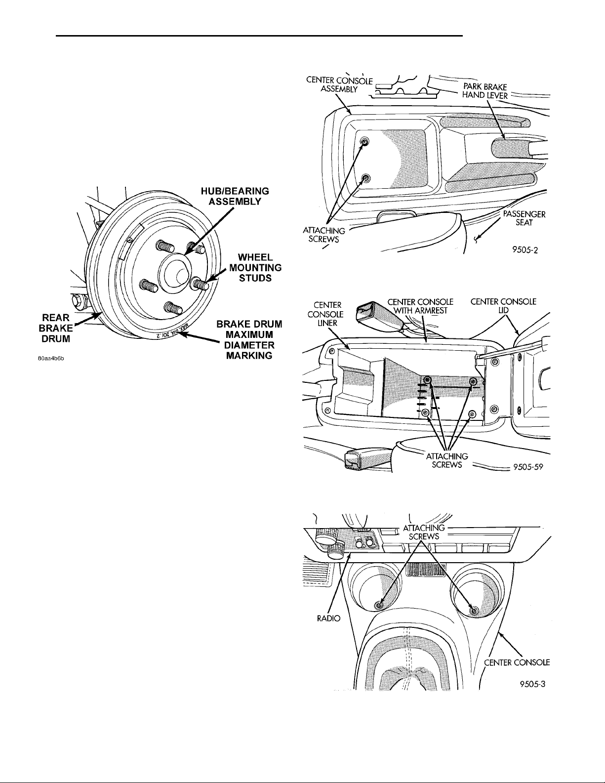
allowable brake drum diameter (Fig. 42).
Fig. 43 Attaching Screws At Rear Of Center Console
W/O Arm Rest
Fig. 42 Brake Drum Maximum Diameter
Identification
PARK BRAKE LEVER AUTO ADJUSTER MECHANISM
WARNING: THE AUTO ADJUSTING FEATURE OF
THIS PARKING BRAKE LEVER CONTAINS A CLOCK
SPRING LOADED TO APPROXIMATELY 20 POUNDS.
DO NOT RELEASE THE AUTO ADJUSTER LOCKOUT DEVICE BEFORE INSTALLING CABLES INTO
THE EQUALIZER. KEEP HANDS OUT OF AUTO
ADJUSTER SECTOR AND PAWL AREA. FAILURE TO
OBSERVE CAUTION IN HANDLING THIS MECHANISM COULD LEAD TO SERIOUS INJURY.
WARNING: WHEN REPAIRS TO THE PARK BRAKE
LEVER OR CABLES IS REQUIRED, THE AUTO
ADJUSTER MUST BE RELOADED AND LOCKED
OUT.
(1) Remove screws attaching rear of center console
assembly to console bracket (Fig. 43) or (Fig. 44).
(2) Remove the 2 screws located in cup holders
(Fig. 45), attaching front of center console assembly
to console bracket.
(3) Raise park brake hand lever assembly as high
as it will go for required clearance to remove center
console.
(4) Remove center console assembly from vehicle.
(5) Lower park brake lever handle.
Fig. 44 Attaching Screws At Rear Of Center Console
With Arm Rest
Fig. 45 Attaching Screws At Front Of Center
Console
Page 24
5 - 24 BRAKES PL
SERVICE PROCEDURES (Continued)
CONSOLEBRACKET
PARK BRAKE ASSEMBLY
OUTPUT CABLE
PARK BRAKE LEVER ASSEM-
GRASP PIN WITH PLIERS
AND QUICKLY REMOVE
BLY
FROM PARK BRAKE
LEVER ASSEMBLY
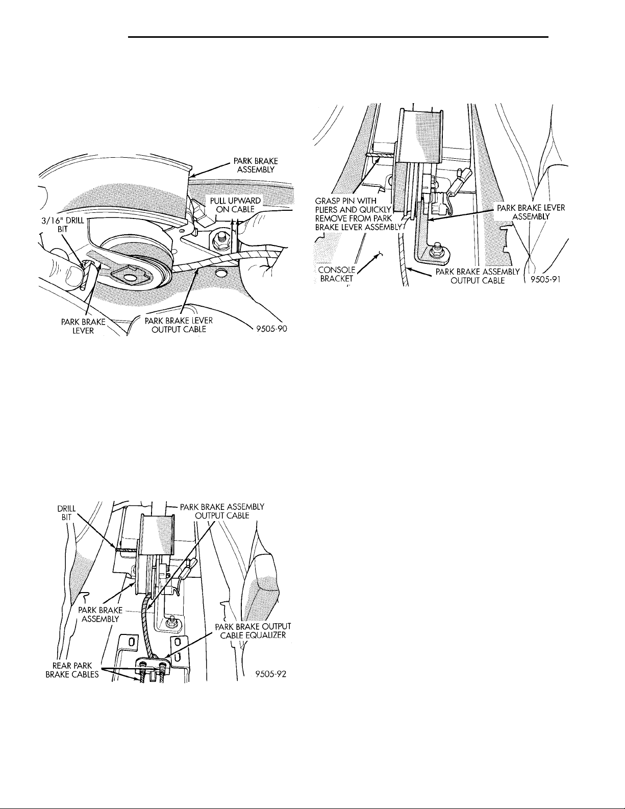
(6) Grasp park brake lever output cable by hand
DRILL BIT PARK BRAKE ASSEMBLY OUT-PUT CABLEPARK BRAKEASSEMBLY
REAR PARK BRAKECABLES
and pull upward (Fig. 46). Continue pulling on cable
until a 3/16 in. drill bit can be inserted into handle
PARK BRAKEASSEMBLYPULL UPWARDON CABLE3/16” DRILL BITPARK BRAKE LEVERPARK BRAKELEVER OUT-PUT CABLE
PARK BRAKE OUTPUT
CABLE EQUALIZER
and sector gear of park brake mechanism (Fig. 46).
This will lock the park brake mechanism and take
tension off park brake cables.
Fig. 46 Locking Pin Installed In Park Brake
Mechanism
RELEASING PARK BRAKE AUTO ADJUSTER
NOTE: The park brake lever can be in any position
when releasing the auto adjuster. To ease installation of center console, it is advisable to pull park
brake lever handle all the way up before removing
lockout pin
(1) Be sure rear park brake cables are properly
installed in the equalizer (Fig. 47).
mechanism. This will allow the park brake lever
mechanism to correctly adjust the park brake cables.
Fig. 48 Removing Lockout Pin From Park Brake
Lever
(4) Install center console.
(5) Install the 4 console assembly attaching screws
(Fig. 43) or (Fig. 44).
(6) Cycle park brake lever once to position park
brake cables. Then return the park brake lever its
released position. Check the rear wheels of the vehicle, they should rotate freely without dragging.
BRAKE TUBE REPAIR
Only double wall 4.75mm (3/16 in.) steel tubing
with Al-rich/ZN-AL alloy coating and the correct tube
nuts are to be used for replacement of a hydraulic
brake tube.
Care should be taken when repairing brake tubing,
to be sure the proper bending and flaring tools and
procedures are used, to avoid kinking. Do not route
the tubes against sharp edges, moving components or
into hot areas. All tubes should be properly attached
with recommended retaining clips.
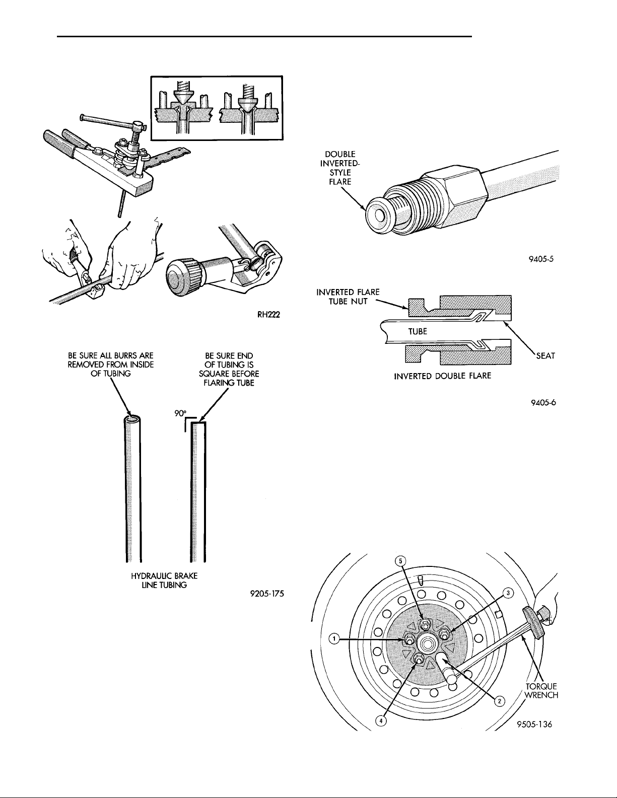
Using Tubing Cutter, Special Tool C-3478-A or
equivalent, cut off damaged seat or tubing (Fig. 49).
Ream out any burrs or rough edges showing on
inside of tubing (Fig. 50). This will make the ends of
tubing square (Fig. 50) and ensure better seating of
flared end tubing. PLACE TUBE NUT ON TUB-
ING BEFORE FLARING THE TUBING.
Fig. 47 Park Brake Cables Properly Installed In
Equalizer
(2) Pull park brake lever handle all the way up.
(3) Firmly grasp park brake lever locking pin (Fig.
48), and quickly remove it from the park brake lever
DOUBLE INVERTED TUBING FLARES
To make a double inverted tubing flare (Fig. 51)
and (Fig. 52). Open handles of Flaring Tool, Special
Tool C-4047 or equivalent. Then rotate jaws of tool
until the mating jaws of tubing size are centered
between vertical posts on tool. Slowly close handles
with tubing inserted in jaws but do not apply heavy
pressure to handle as this will lock tubing in place.
Page 25
INVERTED FLARETUBE NUT SEATINVERTED DOUBLE FLARETUBE
BE SURE ALL BURRSARE REMOVED FROMINSIDE OF TUBING BE SURE END OF TUBING ISSQUARE BEFORE FLARINGTUBEHYDRAULIC BRAKE LINETUBING
DOUBLE INVERTED-STYLEFLARE
PL BRAKES 5 - 25
SERVICE PROCEDURES (Continued)
tinue to screw down until tool is firmly seated in tubing. Remove tubing from flaring tool and inspect
seat. Refer to tube routing diagrams for proper brake
tube routing and clip locations. Replace any damaged
tube routing clips.
Fig. 51 Double Inverted Brake Line Tubing Flare
Fig. 49 Cutting And Flaring Of Brake Fluid Tubing
Fig. 50 Brake Fluid Tube Preparation For Flaring
Place gauge (Form A) on edge over end of brake
tubing. Push tubing through jaws until end of tubing
contacts the recessed notch in gauge matching the
tubing size. Squeeze handles of flaring tool and lock
tubing in place. Place 3/16 inch plug of gauge (A)
down in end of tubing. Swing compression disc over
gauge and center tapered flaring screw in recess of
disc. Screw in until plug gauge has seated on jaws of
flaring tool. This action has started to invert the
extended end of the tubing. Remove gauge and con-
Fig. 52 Double Wall Inverted Flare Connection
REMOVAL AND INSTALLATION
WHEEL AND TIRE ASSEMBLY
To install the wheel and tire assembly, first position it properly on the mounting surface using the
hub pilot as a guide. Then progressively tighten the
lug nuts in the proper sequence (Fig. 53) to half of
the required torque. Finally tighten the lug nuts in
the proper sequence (Fig. 53) to 129 N·m (95 ft. lbs.).
Never use oil or grease on studs or nuts.
Fig. 53 Wheel Nut Tightening Sequence
TORQUEWRENCH
Page 26
DISC BRAKE CALI-PER ASSEMBLY DRIVESHAFTCALIPER ASSEMBLY GUIDEPIN BOLTSSTEERINGKNUCKLE BRAKING DISC LOWER CONTROLARM
DISC BRAKE CALIPERSLIDE THIS END OF CALI-PER FROM UNDER STEER-ING KNUCKLEROTORLIFT THIS END OF CALIPERAWAY FROM STEERINGKNUCKLE FIRST
WIREHANGER STEERINGKNUCKLE BRAKEDISCDISC BRAKE CALIPERASSEMBLY BRAKE HYDRAULICHOSE
5 - 26 BRAKES PL
REMOVAL AND INSTALLATION (Continued)
FRONT DISC BRAKE CALIPER
REMOVE
During service procedures, grease or any other foreign material must be kept off caliper assembly, surfaces of braking rotor and external surfaces of hub.
Handling of the braking rotor and caliper should
be done in such a way as to avoid deformation of the
rotor and scratching or nicking of the brake linings.
During removal and installation of a wheel and
tire assembly, use care not to strike the caliper.
(1) Raise vehicle on jackstands or centered on a
hoist. See Hoisting in the Lubrication and Maintenance section of this service manual for the required
lifting procedure for this vehicle.
(2) Remove the front wheel and tire assemblies
from this vehicle.
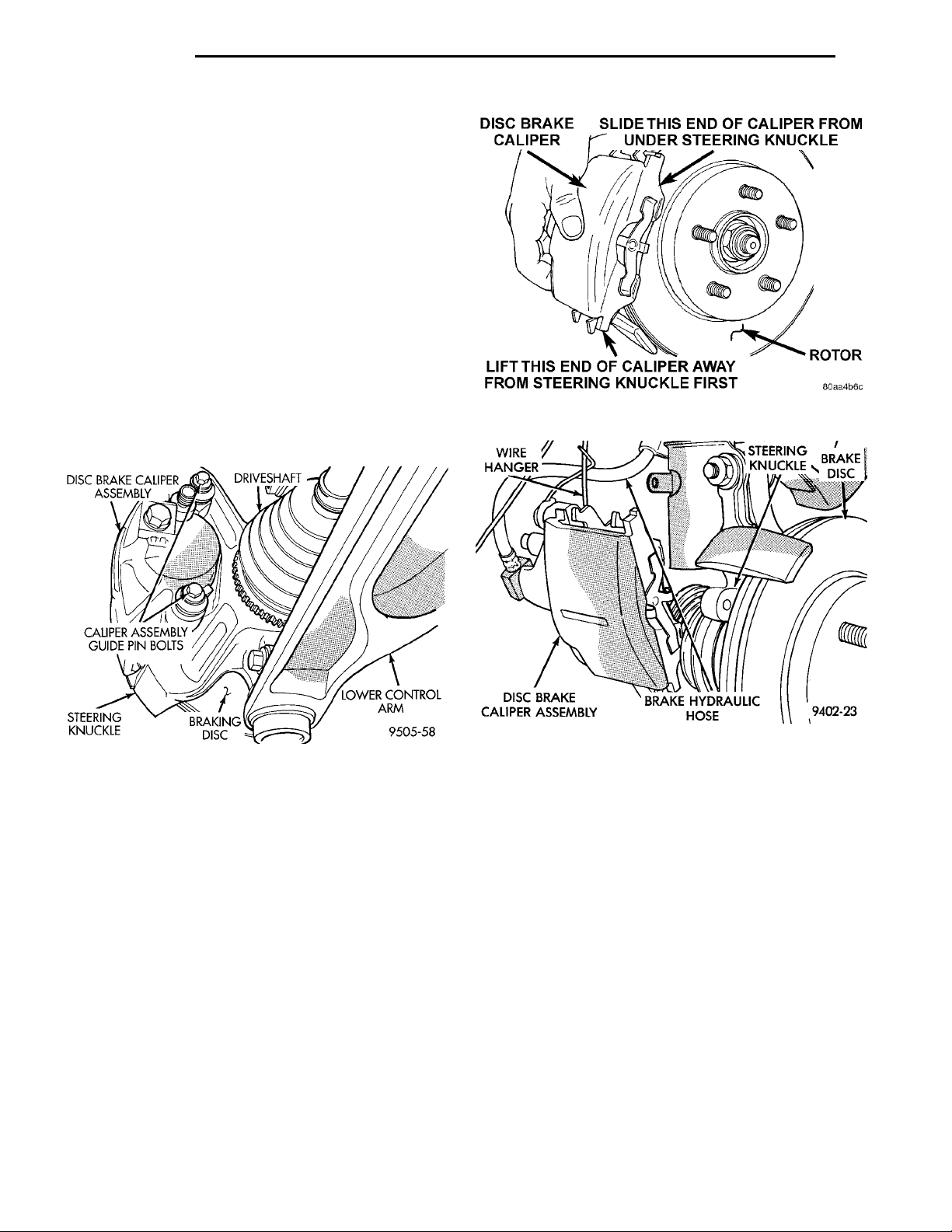
(3) Remove the 2 brake caliper to steering knuckle
guide pin bolts (Fig. 54).
Fig. 55 Removing Caliper Assembly From Steering
Knuckle
Fig. 54 Caliper Guide Pin Bolts
(4) Remove caliper from steering knuckle, by first
rotating free end of caliper away from steering
knuckle. Then slide opposite end of caliper out from
under machined abutment on steering knuckle (Fig.
55).
(5) Support the disc brake caliper firmly using a
wire hanger (Fig. 56). This is required to prevent the
weight of the caliper from damaging the flexible
brake hose .
INSTALL
NOTE: Step 1 below is only required when installing a caliper after new brake shoes have been
installed.
(1) Completely retract the caliper piston back into
the bore of the caliper.
(2) Lubricate both steering knuckle abutments
with a liberal amount of Mopart Multipurpose Lubricant, or equivalent.
(3) If removed, install the front rotor on the hub,
making sure it is squarely seated on face of hub.
Fig. 56 Storing Disc Brake Caliper
CAUTION: Use care when installing the caliper
assembly onto the steering knuckle so the seals on
the caliper guide pin bushings do not get damaged
by the steering knuckle bosses.
(4) Carefully position the brake caliper and brake
shoes on the steering knuckle by first hooking the
end of the caliper under the edge of the steering
knuckle as shown in (Fig. 57). Then rotate caliper
into position on the steering knuckle.
(5) Install the caliper guide pin bolts and tighten
to 18 to 20 N·m (192 in. lbs.) (Fig. 54). Extreme
caution should be taken not to cross thread the
caliper guide pin bolts.
(6) Install the wheel and tire assembly.
(7) Tighten the wheel mounting stud nuts in
proper sequence until all nuts are torqued to half
specification. Then repeat the tightening sequence to
the full specified torque of 135 N·m (100 ft. lbs.).
(8) Remove jackstands or lower hoist. Before mov-
ing vehicle, pump the brake pedal several times to
insure the vehicle has a firm brake pedal.
Page 27
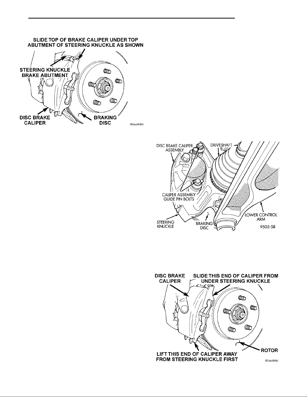
SLIDE TOP OF BRAKE CALI-PER UNDER TOP ABUT-MENT OF STEERINGKNUCKLE AS SHOWNBRAKING DISCDISC BRAKE CALIPERSTEERING KNUCKLE BRAKEABUTMENT
PL BRAKES 5 - 27
REMOVAL AND INSTALLATION (Continued)
If inspection reveals that the square sectioned caliper piston seal is worn or damaged, it should be
replaced immediately.
During removal and installation of a wheel and
tire assembly, use care not to strike the caliper.
NOTE: Before vehicle is moved after any brake
service work, pump the brake pedal several times
to insure the vehicle has a firm brake pedal.
REMOVE
(1) Raise vehicle on jackstands or centered on a
hoist. See Hoisting in the Lubrication and Maintenance section of this manual.
(2) Remove the front wheel and tire assemblies
from vehicle.
Fig. 57 Installing Caliper Assembly On Steering
Knuckle
(9) Road test the vehicle and make several stops to
wear off any foreign material on the brakes and to
seat the brake pads.
(3) Remove the 2 guide pin bolts (Fig. 58) mount-
ing the caliper to the steering knuckle .
FRONT DISC BRAKE SHOES
WARNING: ALTHOUGH FACTORY INSTALLED
BRAKELININGS ARE MADE FROM ASBESTOS FREE
MATERIALS, SOME AFTER MARKET BRAKELINING
MAY CONTAIN ASBESTOS. THIS SHOULD BE TAKEN
INTO ACCOUNT WHEN SERVICING A VEHICLE’S
BRAKE SYSTEM, WHEN AFTERMARKET BRAKELININGS MAY HAVE BEEN INSTALLED ON THE VEHICLE.
ALWAYS WEAR A RESPIRATOR WHEN CLEANING
BRAKE COMPONENTS AS ASBESTOS CAN CAUSE
SERIOUS BODILY HARM SUCH AS ASBESTOSIS AND
OR CANCER. NEVER CLEAN BRAKE COMPONENTS
BY USING COMPRESSED AIR, USE ONLY A VACUUM
CLEANER SPECIFICALLY DESIGNED FOR THE
REMOVAL OF BRAKE DUST. IF A VACUUM CLEANER
IS NOT AVAILABLE, CLEAN BRAKE PARTS USING
ONLY WATER DAMPENED SHOP TOWELS. DO NOT
CREATE BRAKELINING DUST BY SANDING BRAKE
LININGS WHEN SERVICING A VEHICLE. DISPOSE OF
ALL DUST AND DIRT SUSPECTED OF CONTAINING
ASBESTOS FIBERS USING ONLY SEALED AIRTIGHT
BAGS OR CONTAINERS. FOLLOW ALL RECOMMENDED SAFETY PRACTICES PRESCRIBED BY THE
OCCUPATIONAL SAFETY AND HEALTH ADMINISTRATION (OSHA) AND THE ENVIRONMENTAL PROTECTION AGENCY (EPA), FOR HANDLING AND DISPOSAL
OF PRODUCTS CONTAINING ASBESTOS.
During service procedures, grease or any other foreign material must be kept off caliper assembly, surfaces of braking rotor and external surfaces of hub.
Handling of the braking rotor and caliper should
be done in such a way as to avoid deformation of the
rotor and scratching or nicking of the brake linings.
Fig. 58 Caliper Guide Pin Bolts
DISC BRAKE CALIPERSLIDE THIS END OF CALI-PER FROM UNDER STEER-ING KNUCKLEROTORLIFT THIS END OF CALIPERAWAY FROM STEERINGKNUCKLE FIRST
(4) Remove brake caliper from steering knuckle, by
first rotating free end of caliper away from steering
knuckle. Then slide opposite end of caliper out from
under machined abutment on steering knuckle (Fig.
59).
Fig. 59 Removing Caliper From Steering Knuckle
Page 28
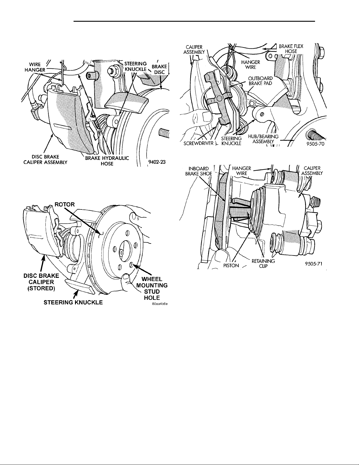
WIREHANGER STEERINGKNUCKLE BRAKEDISCDISC BRAKE CALIPERASSEMBLY BRAKE HYDRAULICHOSE
ROTORWHEEL MOUNTING STUDHOLESTEERING KNUCKLEDISC BRAKE CALIPER(STORED)
INBOARDBRAKE SHOE HANGERWIRE CALIPERASSEMBLYRETAININGCLIPPISTON
BRAKE FLEXHOSEHANGERWIREOUTBOARDBRAKE PADHUB/BEARINGASSEMBLYSTEERING KNUCKLESCREWDRIVERCALIPERASSEMBLY
5 - 28 BRAKES PL
REMOVAL AND INSTALLATION (Continued)
(5) Support caliper firmly to prevent weight of cal-
iper from damaging the flexible brake hose (Fig. 60).
Fig. 62 Removing Outboard Brake Shoe
Fig. 60 Storing Caliper
(6) Remove brake rotor from hub by pulling it
straight off the wheel mounting studs (Fig. 61).
Fig. 61 Removing/Installing Brake Rotor
(7) Remove outboard brake shoe by prying the
shoe retaining clip over raised area on caliper. Then
slide the brake shoe down and off the caliper (Fig.
62).
(8) Pull the inboard brake shoe away from the caliper piston until the retaining clip is out of the cavity
in the piston. (Fig. 63).
CALIPER INSPECTION
Check caliper for piston seal leaks (brake fluid in
and around boot area and inboard lining) and for any
ruptures of the piston dust boot. If boot is damaged,
or fluid leak is visible, disassemble caliper and
install a new seal and boot, (and piston if scored).
Refer to Caliper Disassembly And Re-Assembly Procedures in Disc Brake Caliper Service in this section
of the service manual.
Fig. 63 Removing Inboard Brake Shoe
Check the caliper dust boot and caliper pin bushings to determine if they are in good condition.
Replace if they are damaged, dry, or found to be brittle. Refer to Guide Pin Bushing Service in Disc
Brake Caliper Service in this section of the service
manual.
INSTALL
(1) Completely retract caliper piston back into piston bore of caliper. This is required for caliper installation with new brake shoe assemblies.
(2) Lubricate both steering knuckle abutments
with a liberal amount of Mopart Multipurpose Lubricant, or equivalent.
(3) Install the front rotor on the hub, making sure
it is squarely seated on face of hub (Fig. 61).
(4) Remove the protective paper from the noise
suppression gasket on both the inner and outer brake
shoes (if equipped).
NOTE: Note: The inboard and outboard brake
shoes are not common (Fig. 64).
Page 29
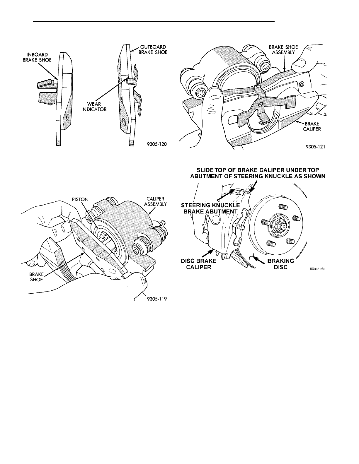
PL BRAKES 5 - 29
REMOVAL AND INSTALLATION (Continued)
Fig. 64 Front Brake Shoe Identification
(5) Install the new inboard brake shoe into the caliper piston by firmly pressing into piston bore with
thumbs (Fig. 65). Be sure inboard brake shoe is positioned squarely against the face of the caliper piston.
PISTONBRAKE SHOE CALIPERASSEMBLY
Fig. 65 Installing Inboard Brake Shoe
(6) Slide the new outboard brake shoe onto the caliper (Fig. 66).
CAUTION: Use care when installing the caliper
onto the steering knuckle so the seals on the caliper guide pin bushings do not get damaged by the
steering knuckle bosses.
Fig. 66 Installing Outboard Brake Shoe
Fig. 67 Installing Caliper On Steering Knuckle
(10) Tighten the wheel mounting stud nuts in
proper sequence until all nuts are torqued to half
specification. Then repeat the tightening sequence to
the full specified torque of 135 N·m (100 ft. lbs.).
(11) Remove jackstands or lower hoist. Before
moving vehicle, pump the brake pedal several
times to insure the vehicle has a firm brake
pedal.
(12) Road test the vehicle and make several stops
to wear off any foreign material on the brakes and to
seat the brake pads.
(7) Carefully position the brake caliper and brake
shoes over the rotor by hooking the end of the caliper
under the steering knuckle (Fig. 67). Then rotate caliper into position on steering knuckle.
(8) Install the caliper guide pin bolts (Fig. 58) and
tighten to 18 to 20 N·m (192 in. lbs.). Extreme cau-
tion should be taken not to cross thread the
caliper guide pin bolts.
(9) Install the wheel and tire assembly.
REAR DISC BRAKE CALIPER
REMOVE
(1) Raise vehicle on jackstands or centered on a
hoist. See Hoisting in the Lubrication and Maintenance section of this manual.
(2) Remove rear wheel and tire assemblies from
vehicle.
Page 30
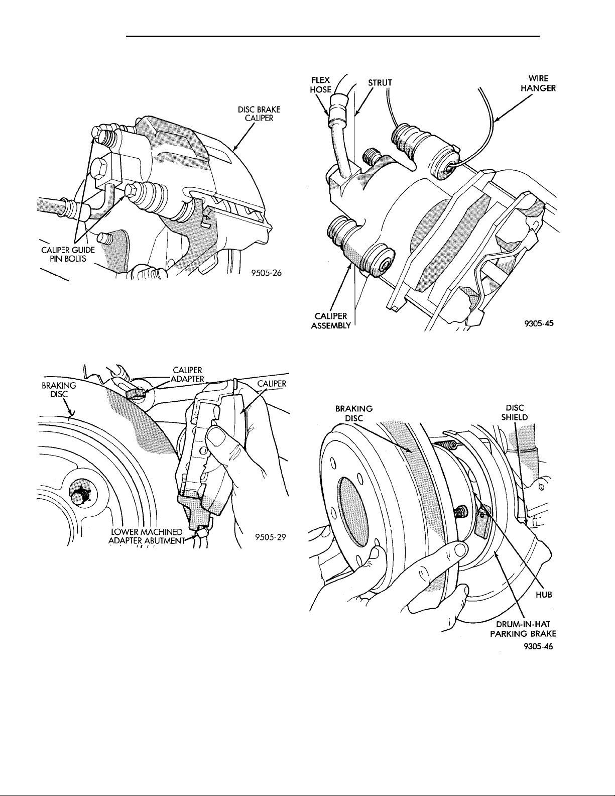
BRAKINGDISC CALIPERADAPTER
LOWER MACHINEDADAPTER ABUTMENT
DISC BRAKE CALIPERCALIPER GUIDE PINBOLTS
CALIPER
FLEXHOSE STRUT WIRE HANGERCALIPERASSEMBLY
BRAKINGDISC DISCSHIELD HUBDRUM-IN-HAT PARKINGBRAKE
5 - 30 BRAKES PL
REMOVAL AND INSTALLATION (Continued)
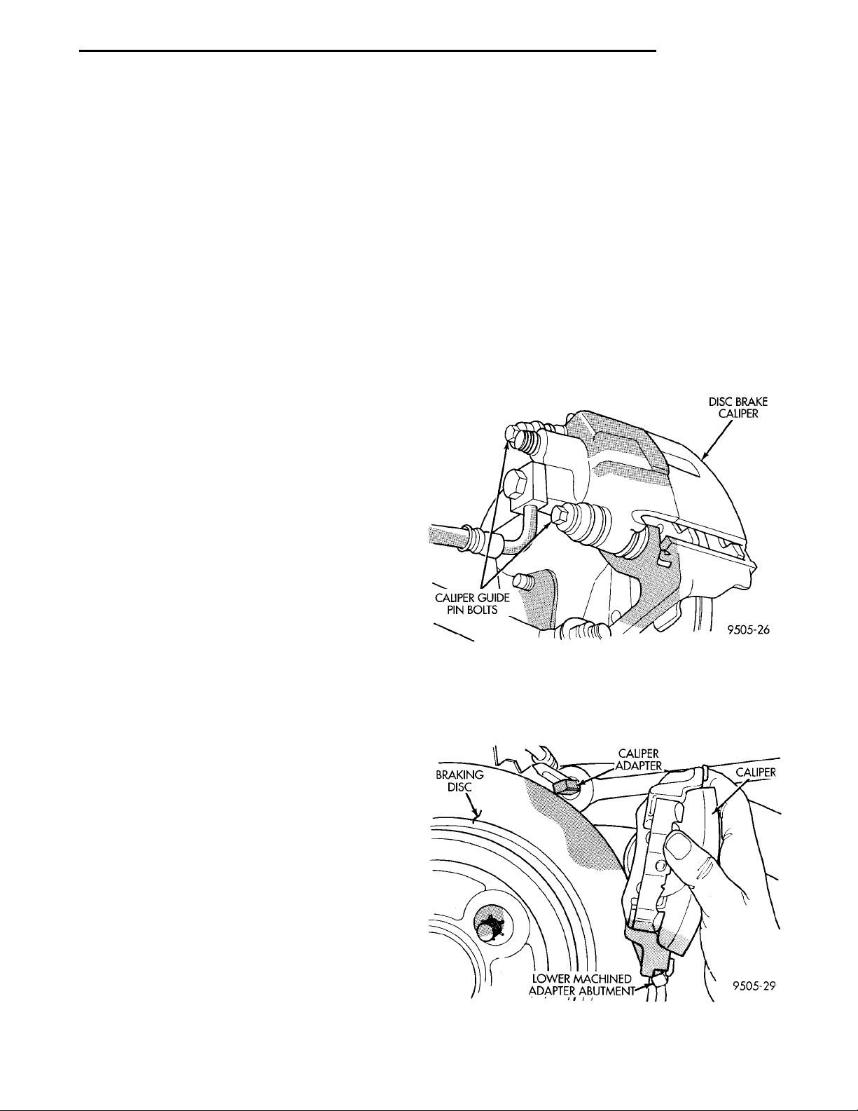
(3) Remove the 2 caliper assembly to adapter
guide pin bolts (Fig. 68).
Fig. 68 Caliper Assembly Guide Pin Bolts
(4) Remove caliper assembly from adapter and
rotor by first rotating top of caliper assembly away
from adapter, and then lifting caliper assembly off
lower machined abutment on adapter (Fig. 69).
(3) If removed, install the rear rotor on the hub
making sure it is squarely seated on the face of the
hub (Fig. 71).
Fig. 70 Storing Caliper
Fig. 69 Removing Caliper Assembly From Adapter
(5) Support caliper assembly firmly from rear strut
to prevent weight of caliper from damaging the flexible brake hose (Fig. 70).
INSTALL
NOTE: Step 1 below is only required when installing the disc brake caliper, after new brake shoes
have been installed.
(1) Completely retract caliper piston back into piston bore of caliper assembly.
(2) Lubricate both adapter abutments with a liberal amount of Mopart Multipurpose Lubricant, or
equivalent.
Fig. 71 Installing Rear Rotor
CAUTION: Use care when installing caliper assembly
onto adapter so the guide pin bushings and sleeves
do not get damaged by the mounting bosses on
adapter.
(4) Carefully lower caliper and brake shoe assem-
blies over braking disc (rotor) reversing the required
Page 31
PL BRAKES 5 - 31
REMOVAL AND INSTALLATION (Continued)
removal procedure (Fig. 69). Make sure that the caliper guide pin bolts, bushings and sleeves are clear of
the adapter bosses.
CAUTION: Extreme caution should be taken not to
cross thread the caliper guide pin bolts when they
are installed.
(5) Install caliper assembly guide pin bolts into
adapter and tighten (Fig. 68). Then torque both guide
pin bolts to 22 N·m (192 in. lbs.).
(6) Install the wheel and tire assembly.
(7) Tighten the wheel mounting stud nuts in
proper sequence until all nuts are torqued to half
specification. Then repeat the tightening sequence to
the full specified torque of 135 N·m (100 ft. lbs.).
(8) Remove jackstands or lower hoist. Before
moving vehicle, pump the brake pedal several
times to insure the vehicle has a firm brake
pedal. .
(9) Road test the vehicle and make several stops to
wear off any foreign material on the brakes and to
seat the brake pads.
REAR DISC BRAKE SHOES
WARNING: ALTHOUGH FACTORY INSTALLED
BRAKELININGS ARE MADE FROM ASBESTOS FREE
MATERIALS, SOME AFTER MARKET BRAKELINING
MAY CONTAIN ASBESTOS. THIS SHOULD BE TAKEN
INTO ACCOUNT WHEN SERVICING A VEHICLE’S
BRAKE SYSTEM, WHEN AFTERMARKET BRAKELININGS MAY HAVE BEEN INSTALLED ON THE VEHICLE.
ALWAYS WEAR A RESPIRATOR WHEN CLEANING
BRAKE COMPONENTS AS ASBESTOS CAN CAUSE
SERIOUS BODILY HARM SUCH AS ASBESTOSIS AND
OR CANCER. NEVER CLEAN BRAKE COMPONENTS
BY USING COMPRESSED AIR, USE ONLY A VACUUM
CLEANER SPECIFICALLY DESIGNED FOR THE
REMOVAL OF BRAKE DUST. IF A VACUUM CLEANER
IS NOT AVAILABLE, CLEAN BRAKE PARTS USING
ONLY WATER DAMPENED SHOP TOWELS. DO NOT
CREATE BRAKELINING DUST BY SANDING BRAKE
LININGS WHEN SERVICING A VEHICLE. DISPOSE OF
ALL DUST AND DIRT SUSPECTED OF CONTAINING
ASBESTOS FIBERS USING ONLY SEALED AIRTIGHT
BAGS OR CONTAINERS. FOLLOW ALL RECOMMENDED SAFETY PRACTICES PRESCRIBED BY THE
OCCUPATIONAL SAFETY AND HEALTH ADMINISTRATION (OSHA) AND THE ENVIRONMENTAL PROTECTION AGENCY (EPA), FOR HANDLING AND DISPOSAL
OF PRODUCTS CONTAINING ASBESTOS.
During service procedures, grease or any other foreign material must be kept off caliper assembly, surfaces of braking rotor and external surfaces of hub.
Handling of the braking rotor and caliper should
be done in such a way as to avoid deformation of the
rotor and scratching or nicking of the brake linings.
If inspection reveals that the square sectioned caliper piston seal is worn or damaged, it should be
replaced immediately.
During removal and installation of a wheel and
tire assembly, use care not to strike the caliper.
NOTE: Before vehicle is moved after any brake
service work, pump the brake pedal several times
to insure the vehicle has a firm brake pedal.
REMOVE
(1) Raise vehicle on jackstands or centered on a
hoist. See Hoisting in the Lubrication and Maintenance section of this manual.
(2) Remove rear wheel and tire assemblies from
vehicle.
(3) Remove the 2 caliper assembly to adapter
guide pin bolts (Fig. 72).
Fig. 72 Caliper Assembly Guide Pin Bolts
BRAKINGDISC CALIPERADAPTER
LOWER MACHINEDADAPTER ABUTMENT
CALIPER
(4) Remove caliper assembly from adapter and
rotor by first rotating top of caliper assembly away
from adapter, and then lifting caliper assembly off
lower machined abutment on adapter (Fig. 73).
Fig. 73 Removing/Installing Caliper Assembly From
Adapter
Page 32
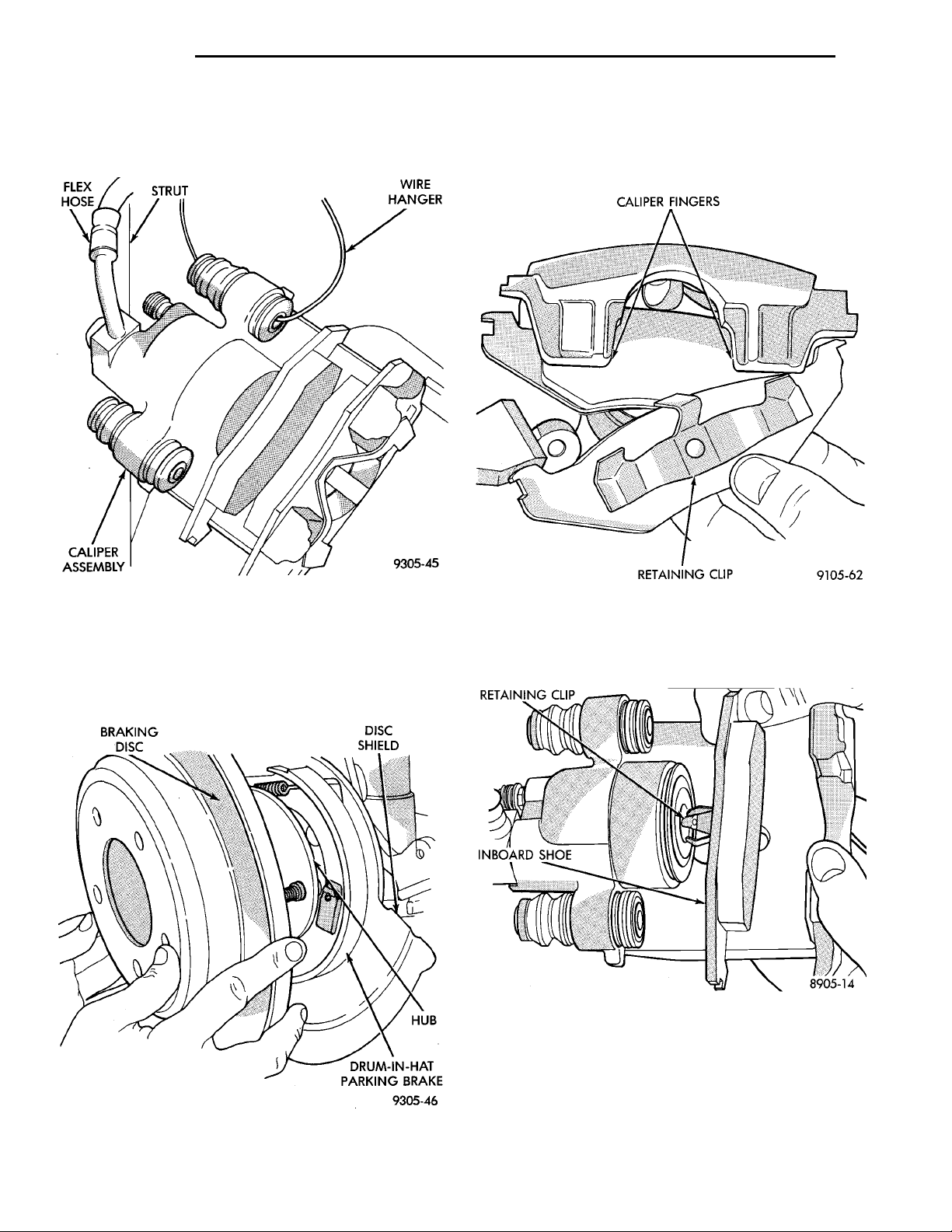
FLEXHOSE STRUT WIRE HANGERCALIPERASSEMBLY
BRAKINGDISC DISCSHIELD HUBDRUM-IN-HAT PARKINGBRAKE
CALIPER FINGERSRETAINING CLIP
5 - 32 BRAKES PL
REMOVAL AND INSTALLATION (Continued)
(5) Support caliper assembly firmly from rear strut
to prevent weight of caliper from damaging the flexible brake hose (Fig. 74).
(7) Remove outboard brake pad from caliper by
prying brake pad retaining clip over raised area on
caliper. Then slide brake pad down and off the caliper (Fig. 76).
Fig. 74 Storing Caliper
(6) Remove rear rotor from hub/bearing assembly
(Fig. 75). Then inspect drum-in-hat parking brake
shoes and parking brake braking surface on rotor for
any signs of excessive wear or damage. Replace parking brake shoes if required.
Fig. 75 Rear Brake Rotor
RETAINING CLIPINBOARD SHOE
Fig. 76 Outboard Brake Shoe
(8) Pull inboard brake pad away from caliper piston, until retaining clip is free from cavity in piston.
(Fig. 77).
Fig. 77 Removing Inboard Brake Shoe
CALIPER INSPECTION
Check caliper for piston seal leaks (brake fluid in
and around boot area and inboard lining) and for any
ruptures of the piston dust boot. If boot is damaged,
or fluid leak is visible, disassemble caliper and
install a new seal and boot, (and piston if scored).
Refer to Caliper Disassembly And Re-Assembly Pro-
Page 33
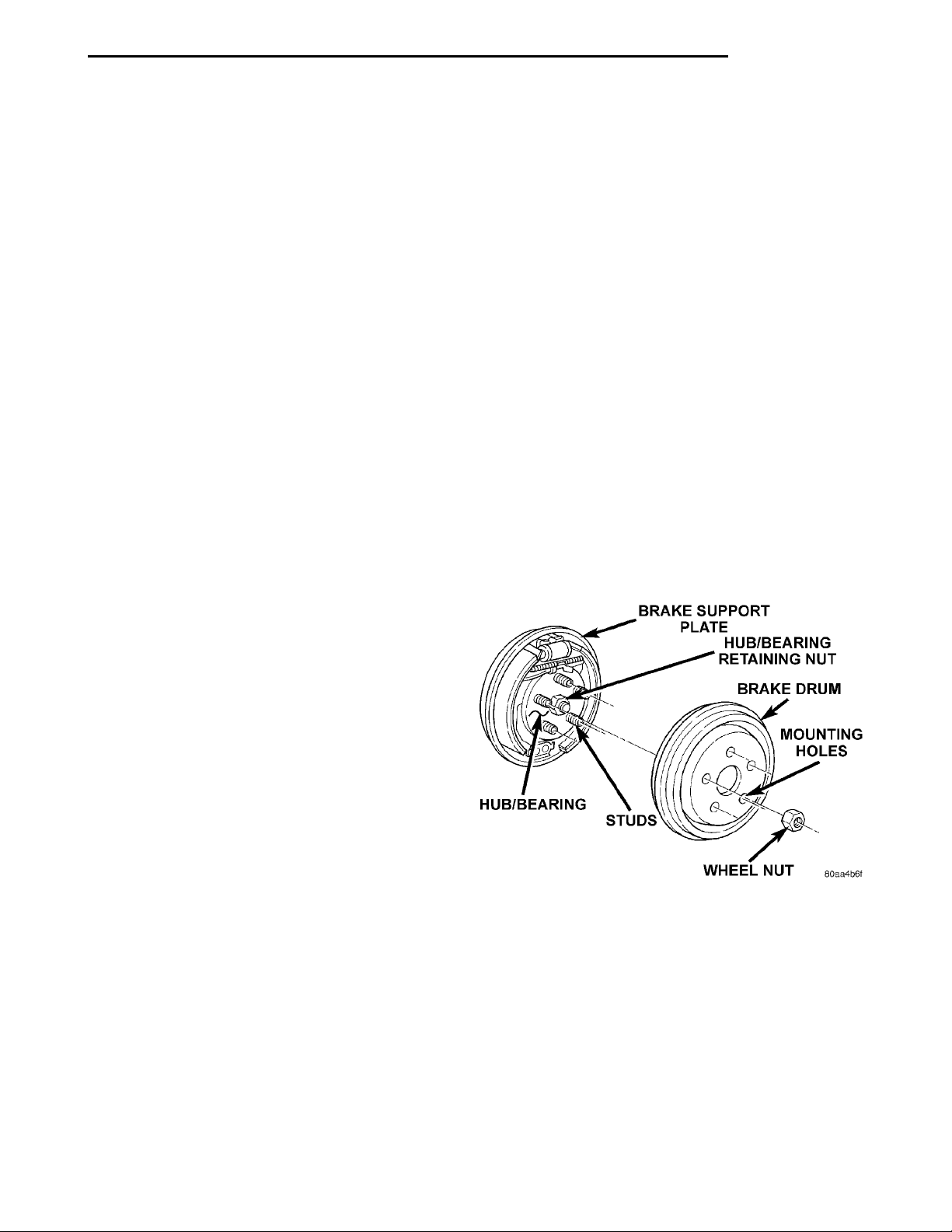
PL BRAKES 5 - 33
REMOVAL AND INSTALLATION (Continued)
cedures in Disc Brake Caliper Service in this section
of the service manual.
Check the caliper dust boot and caliper pin bushings to determine if they are in good condition.
Replace if they are damaged, dry, or found to be brittle. Refer to Guide Pin Bushing Service in Disc
Brake Caliper Service in this section of the service
manual.
INSTALL
(1) Completely retract the caliper piston back into
the piston bore of the caliper assembly. This is
required for caliper installation when new brake pad
assemblies are installed on caliper.
(2) Lubricate both adapter abutments with a liberal amount of Mopart Multipurpose Lubricant, or
equivalent.
(3) Install rear rotor on the hub making sure it is
squarely seated on face of hub (Fig. 75).
(4) Remove protective paper from noise suppression gasket on both inner and outer brake pad
assemblies (if equipped).
(5) Install new inboard brake shoe assembly into
caliper piston by firmly pressing into piston bore
with thumbs (Fig. 77). Be sure inboard brake
shoe assembly is positioned squarely against
face of caliper piston.
(6) Slide new outboard brake pad assembly onto
the caliper assembly (Fig. 76). Be sure retaining clip
is squarely seated in the depressed areas on the caliper.
times to insure the vehicle has a firm brake
pedal. .
(12) Road test the vehicle and make several stops
to wear off any foreign material on the brakes and to
seat the brake pads.
REAR BRAKE DRUM
REMOVE
Further clearance can be obtained by backing off
the brake automatic adjuster screw. Remove rubber
plug from top of brake support plate. Rotate automatic adjuster screw assembly with an upward
motion, using a medium size screwdriver.
See adjusting rear service brakes in the Service
Adjustments section in this group of the service manual for the specific adjustment procedure.
(1) Raise vehicle on jackstands or centered on a
hoist. See Hoisting in the Lubrication and Maintenance section of this manual.
(2) Remove the rear wheel and tire assemblies
BRAKE SUPPORT PLATEHUB/BEARING RETAININGNUTBRAKE DRUMMOUNTING HOLESWHEEL NUTSTUDSHUB/BEARING
from the vehicle.
(3) Remove rear brake drum to hub retaining clips
(if equipped).
(4) Remove rear brake drum from rear hub/bearing assembly (Fig. 78).
CAUTION: Use care when installing caliper assembly onto adapter, so the guide pin bushings and
sleeves do not get damaged by the mounting
bosses on adapter.
(7) Carefully lower caliper and brake shoe assemblies over braking disc (rotor) reversing the required
removal procedure (Fig. 73). Make sure that caliper
guide pin bolts, bushings and sleeves are clear of the
adapter bosses.
CAUTION: Extreme caution should be taken not to
cross thread the caliper guide pin bolts when they
are installed.
(8) Install caliper assembly guide pin bolts into
adapter and tighten (Fig. 72). Then torque both guide
pin bolts to 22 N·m (192 in. lbs.).
(9) Install the wheel and tire assembly.
(10) Tighten the wheel mounting stud nuts in
proper sequence until all nuts are torqued to half
specification. Then repeat the tightening sequence to
the full specified torque of 135 N·m (100 ft. lbs.).
(11) Remove jackstands or lower hoist. Before
moving vehicle, pump the brake pedal several
Fig. 78 Brake Drum And Hub/Bearing
(5) Inspect brake linings for wear, shoe alignment
and contamination.
INSTALL
(1) Install rear brake drum assembly on rear hub
and bearing assembly.
(2) Install the wheel and tire assembly.
(3) Tighten the wheel mounting stud nuts in
proper sequence until all nuts are torqued to half
specification. Then repeat the tightening sequence to
the full specified torque of 135 N·m (100 ft. lbs.).
Page 34
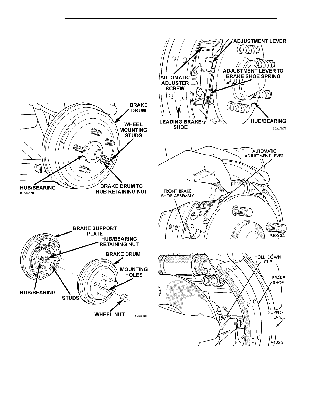
5 - 34 BRAKES PL
REMOVAL AND INSTALLATION (Continued)
REAR BRAKE SHOES
REMOVE
(1) Raise vehicle on jackstands or centered on a
hoist. See Hoisting in the Lubrication and Maintenance section of this manual.
(2) Remove the rear wheel and tire assemblies
from the vehicle.
(3) Remove the brake drum to hub/bearing retaining clips (if equipped) (Fig. 79).
Fig. 81 Automatic Adjustment Lever Spring
BRAKE SUPPORT PLATEHUB/BEARING RETAININGNUTBRAKE DRUMMOUNTING HOLESWHEEL NUTSTUDSHUB/BEARING
Fig. 79 Rear Brake Drum
(4) Remove the brake drum from the hub/bearing
(Fig. 80).
Fig. 80 Brake Drum Remove/Install
(5) Remove the adjustment lever to leading brake
shoe spring (Fig. 81).
(6) Remove the automatic adjustment lever (Fig.
82) from the brake shoe.
(7) Remove hold down clips and pins attaching the
leading and trailing brake shoes to the brake support
plate (Fig. 83).
(8) Remove lower brake shoe to anchor plate
return spring (Fig. 84).
HOLD DOWNCLIPBRAKESHOESUPPORTPLATEPIN
Fig. 82 Automatic Adjustment Lever
Fig. 83 Brake Shoe Hold Down Clips And Pins
(9) Remove the park brake lever pin to rear brake
shoe retaining clip (Fig. 85).
(10) Remove the leading and trailing brake shoe,
upper return spring and automatic adjuster screw
Page 35
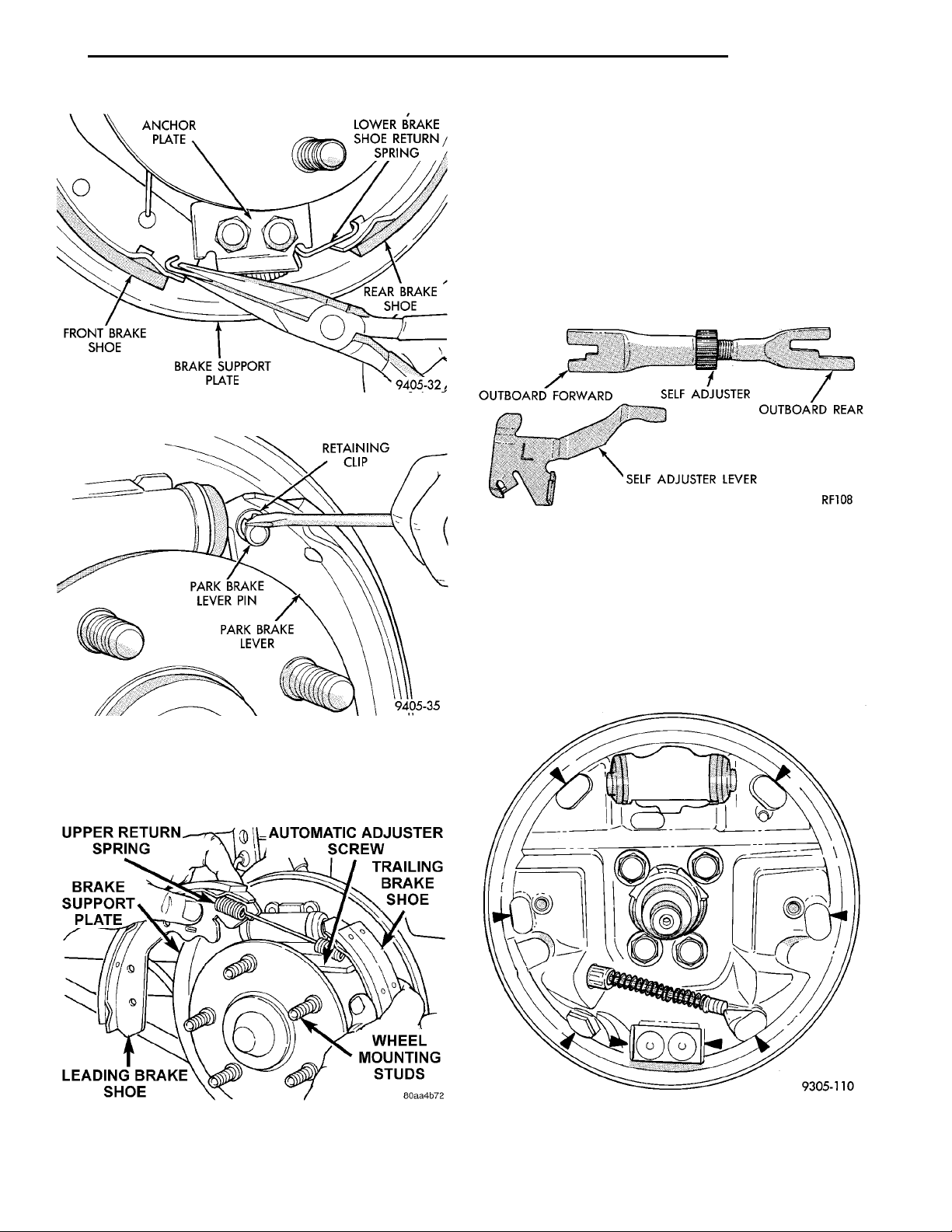
PL BRAKES 5 - 35
REMOVAL AND INSTALLATION (Continued)
CLEANING AND INSPECTION
Clean metal portion of brake shoes. Check to see if
shoes are bent.
Lining should show contact across entire width and
from heel to toe, otherwise replace.
Shoes with lack of contact at toe or heel may be
OUTBOARDFORWARD SEAT ADJUSTER OUTBOARDREARSELF ADJUSTER LEVER
improperly ground.
Clean and inspect support and adjusting screws.
Apply a thin coat of Mopar Multi-Purpose Lubricant
or equivalent to the threads of the self adjuster (Fig.
87). Replace adjusting screw if corroded.
Fig. 84 Brake Shoe To Anchor Plate Return Spring
UPPER RETURN SPRINGAUTOMATIC ADJUSTERSCREWTRAILING BRAKE SHOEWHEEL MOUNTING STUDSLEADING BRAKE SHOEBRAKE SUPPORT PLATE
Fig. 85 Park Brake Lever Pin To Brake Shoe
Retaining Clip
from the brake support plate as an assembly (Fig.
86).
Fig. 87 Adjuster Screw and Lever (Typical)
If old springs have overheated or are damaged,
replace. Overheating indications are paint discoloration or distorted end coils.
INSTALL
(1) Lubricate the eight shoe contact areas on the
support plate and anchor using Mopar Multi-Purpose
Lubricant or equivalent (Fig. 88).
Fig. 86 Remove /Install Brake Shoes
Fig. 88 Shoe Contact Areas on Support Plate
Page 36
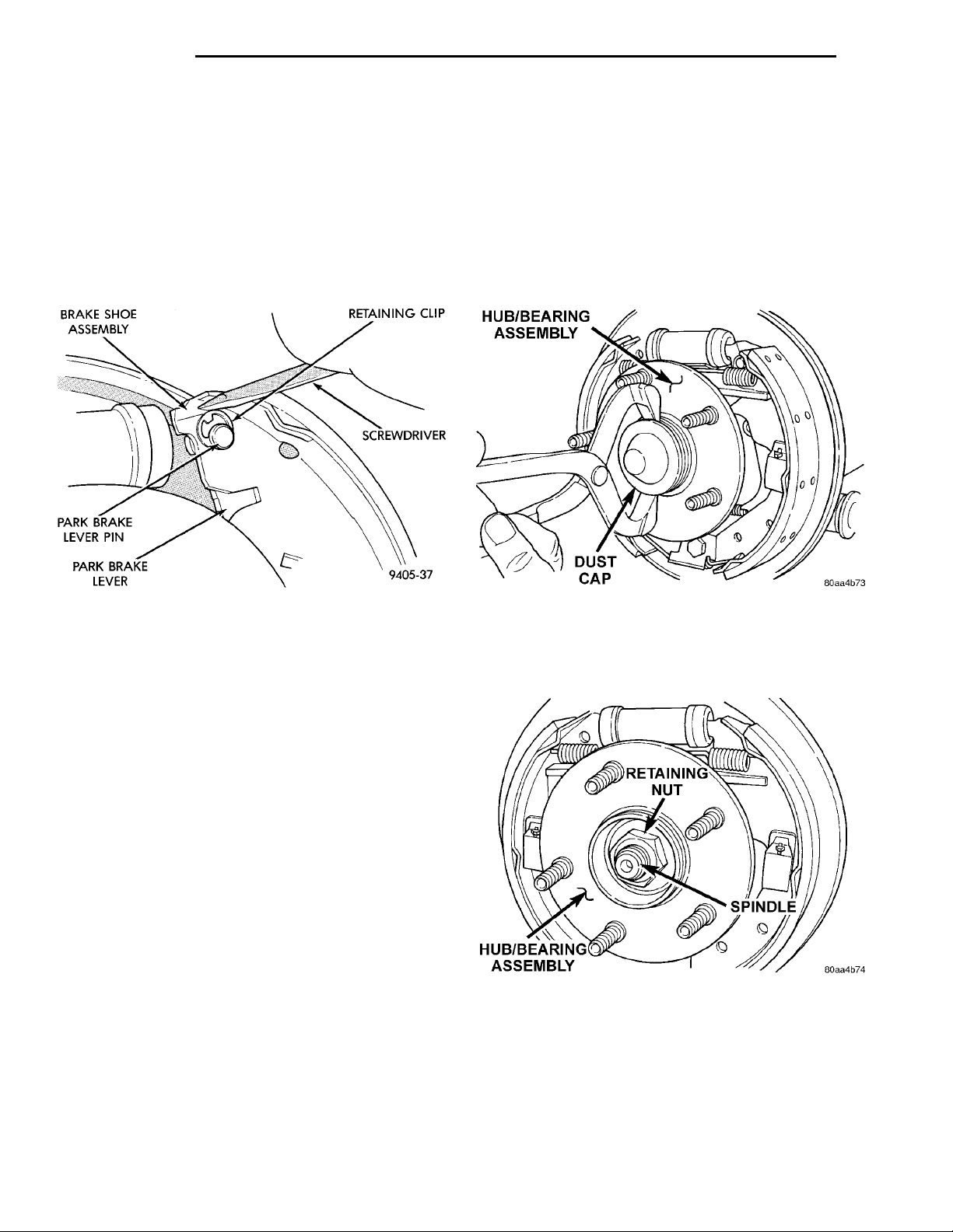
BRAKE SHOE ASSEMBLY RETAININGCLIPSCREWDRIVERPARK BRAKE LEVERPARK BRAKE LEVERPIN
HUB/BEARING ASSEMBLYDUST CAP
RETAINING NUTSPINDLEHUB/BEARING ASSEMBLY
5 - 36 BRAKES PL
REMOVAL AND INSTALLATION (Continued)
(2) Assemble front and rear brake shoe assembly,
automatic adjuster screw and upper return spring
before installation on brake support plate.
(3) Install the pre-assembled brake shoes, automatic adjuster screw and upper return spring on the
brake support plate (Fig. 86).
(4) Install the wave washer on the pin of park
brake lever.
(5) Install pin on park brake lever into hole in rear
brake shoe assembly (Fig. 89).
REAR BRAKE SHOE SUPPORT PLATE
REMOVE
(1) Raise vehicle on jackstands or centered on a
hoist. See Hoisting in the Lubrication and Maintenance section of this manual.
(2) Remove rear tire and wheel assembly from
vehicle.
(3) Remove the dust cap (Fig. 90) from the rear
hub/ bearing.
Fig. 89 Park Brake Lever Pin Retaining Clip
Installation
(6) Install both brake shoe, to brake support plate,
hold down pins and clips (Fig. 83).
(7) Install the lower brake shoe to anchor plate
return spring (Fig. 84).
(8) Install the automatic adjustment lever, on the
front brake shoe of the rear wheel brake assembly
(Fig. 82).
(9) Install the automatic adjustment lever to front
brake shoe assembly spring (Fig. 81).
(10) Adjust brake shoes assemblies so as not to
interfere with brake drum installation.
(11) Install the rear brake drums on the hubs.
(12) Adjust rear brake shoes per Adjusting Rear
Brakes procedure in the service adjustments section
of the service manual.
(13) Install the wheel and tire assembly.
(14) Tighten the wheel mounting stud nuts in
proper sequence until all nuts are torqued to half
specification. Then repeat the tightening sequence to
the full specified torque of 135 N·m (100 ft. lbs.).
(15) Road test vehicle. The automatic adjuster
will continue the brake adjustment during the road
test of the vehicle.
Fig. 90 Hub/ Bearing Dust Cap
(4) Remove the retaining nut (Fig. 91) holding the
rear hub/bearing to the spindle. Remove the hub/
bearing from the spindle.
Fig. 91 Rear Hub/ Bearing Retaining Nut
Page 37
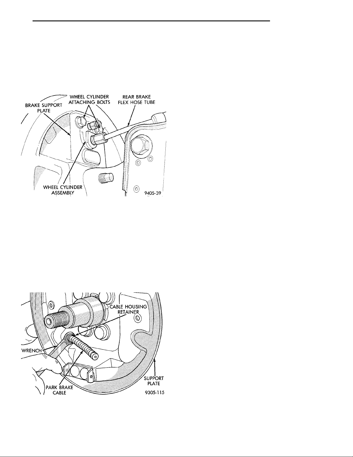
PL BRAKES 5 - 37
REMOVAL AND INSTALLATION (Continued)
(5) Remove the rear brake shoes from the brake
support plate. Refer to Rear Brake Shoes in the
BRAKESUPPORTPLATE WHEEL CYLINDERATTACHING BOLTS REAR BRAKE FLEX HOSETUBEWHEEL CYLINDER ASSEM-BLY
WRENCHCABLE HOUS-ING RETAINER PARK BRAKE CABLESUPPORTPLATE
Removal And Installation Section in this group of the
service manual for the proper brake shoe assembly
removal procedure.
(6) Disconnect the rear brake flex hose tube from
the wheel cylinder (Fig. 92).
Fig. 92 Brake Flex Hose Tube At Wheel Cylinder
(7) Remove park brake actuator lever from the
park brake cable.
(8) Position a 1/2 wrench over the retainer fingers
on the end of the parking brake cable (Fig. 93). Compress cable housing retaining fingers and start cable
housing out of support plate (Fig. 93). Remove
wrench when retainer is free from the park brake
cable mounting hole in the rear brake support plate.
Alternate method is to use a aircraft type hose clamp
over cable housing end fitting compressing the three
fingers.
(9) Remove the 4 brake support plate to knuckle
attaching bolt and washer assemblies. Separate
brake support plate from rear suspension knuckle.
INSTALL
(1) Install brake support plate and gasket on rear
suspension knuckle casting. Torque support plate to
knuckle casting attaching bolts to 75 N·m (55 ft.
lbs.).
(2) Insert parking brake cable end fitting into
brake support plate.
(3) Hand start hydraulic brake hose tube fitting to
wheel cylinder. Torque tube nut to wheel cylinder fitting to 17 N·m (145 in. lbs.).
(4) Attach parking brake cable to the parking
brake actuator.
(5) Install rear brake shoe assemblies on the brake
support plate. Refer to Rear Brake Shoes in the
Removal And Installation Section in this group of the
service manual for the proper brake shoe assembly
installation procedure.
(6) Install rear hub and bearing assembly on rear
spindle. Install a NEW hub and bearing assembly
retaining nut (Fig. 91). Torque hub and bearing
assembly retaining nut to 217 N·m (160 ft. lbs.).
Install dust cap.
(7) Adjust brake shoes assemblies so as not to
interfere with brake drum installation.
(8) Install brake drum. Adjust and bleed service
brakes.
(9) After brake drums are installed, pump brake
pedal several times to do final adjustment of the
brake shoe assemblies.
(10) Install the wheel and tire assembly. Tighten
the wheel mounting stud nuts in proper sequence
until all nuts are torqued to half specification. Then
repeat the tightening sequence to the full specified
torque of 135 N·m (100 ft. lbs.).
Fig. 93 Removing Park Brake Cable From Support
Plate
REAR BRAKE WHEEL CYLINDER
REMOVE
(1) Raise vehicle on jack stands or centered on a
frame contact type hoist. See Hoisting in the Lubrication and Maintenance section of this manual, for
the required lifting procedure to be used for this
vehicle.
(2) Remove the tire and wheel assembly from the
vehicle.
(3) Remove rear brake drum.
(4) Remove rear brake shoe assemblies from the
brake support plate. Refer to Rear Brake Shoes in
the Removal And Installation Section in this group of
the service manual for the proper brake shoe assembly removal procedure.
(5) If brake shoes are wet with grease or brake
fluid, remove and replace.
Page 38
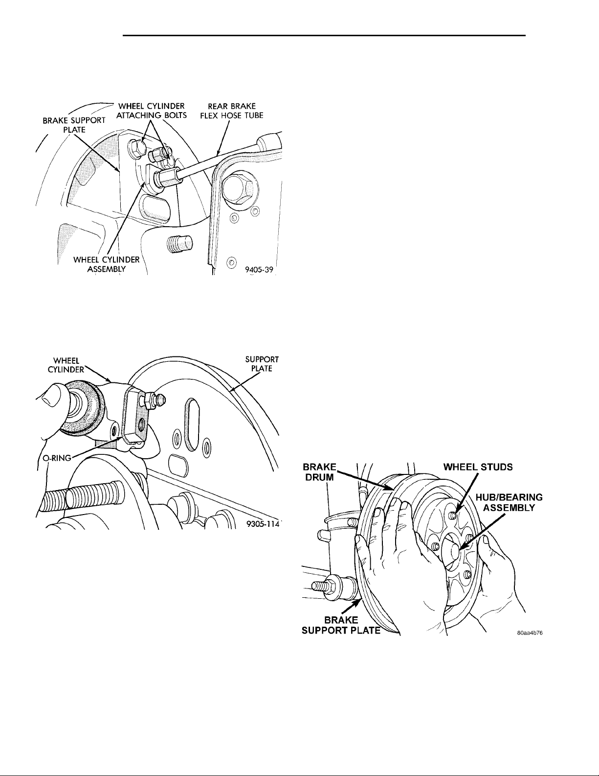
BRAKESUPPORTPLATE WHEEL CYLINDERATTACHING BOLTS REAR BRAKE FLEX HOSETUBEWHEEL CYLINDER ASSEM-BLY
WHEEL CYLIN-DER SUPPORT PLATEO-RING
BRAKE DRUMWHEEL STUDSHUB/BEARING ASSEMBLYBRAKE SUPPORT PLATE
5 - 38 BRAKES PL
REMOVAL AND INSTALLATION (Continued)
(6) Disconnect the rear brake flex hose from the
wheel cylinder (Fig. 94).
Fig. 94 Brake Flex Hose At Wheel Cylinder
(7) Remove rear wheel cylinder attaching bolts
(Fig. 94).
(8) Remove rear wheel cylinder assembly from
brake support plate (Fig. 95).
(4) Install rear brake shoe assemblies on the brake
support plate. Refer to Rear Brake Shoes in the
Removal And Installation Section in this group of the
service manual for the proper brake shoe assembly
installation procedure.
(5) Install rear brake drum onto rear hub.
(6) Install the wheel and tire assembly. Tighten
the wheel mounting stud nuts in proper sequence
until all nuts are torqued to half specification. Then
repeat the tightening sequence to the full specified
torque of 135 N·m (100 ft. lbs.).
(7) Adjust the rear brakes. See Rear Drum Brake
Shoe Adjustment in the Adjustments section in this
group of the service manual.
(8) Bleed the entire brake system. See Bleeding
Brake System in Service Adjustments section in this
group of the service manual.
REAR HUB/BEARING
REMOVE
(1) Raise vehicle on jackstands or centered on a
frame contact type hoist. See Hoisting in the Lubrication and Maintenance section of this manual for
the required lifting procedure to be used for this
vehicle.
(2) Remove rear wheel and tire assembly.
(3) On vehicles equipped with rear drum brakes,
remove brake drum (Fig. 96) from rear hub/bearing
assembly. On vehicles equipped with rear disc
brakes, remove disc brake caliper from disc brake
adapter, and then remove rotor (Fig. 97) from hub/
bearing assembly.
Fig. 95 Remove/Install Wheel Cylinder
INSTALL
(1) Apply a small bead of silicone sealer around
the mating surface of the wheel cylinder to brake
support plate.
NOTE: When installing wheel cylinder on brake
support plate, be sure it is positioned squarely (horizontal) to the brake shoe assemblies.
(2) Install wheel cylinder onto brake support plate.
Tighten the attaching bolts to 13 N·m (115 in. lbs.).
(3) Hand start hydraulic brake hose tube fitting to
wheel cylinder. Torque tube nut to 17 N·m (145 in.
lbs.).
Fig. 96 Brake Drum Removal
Page 39
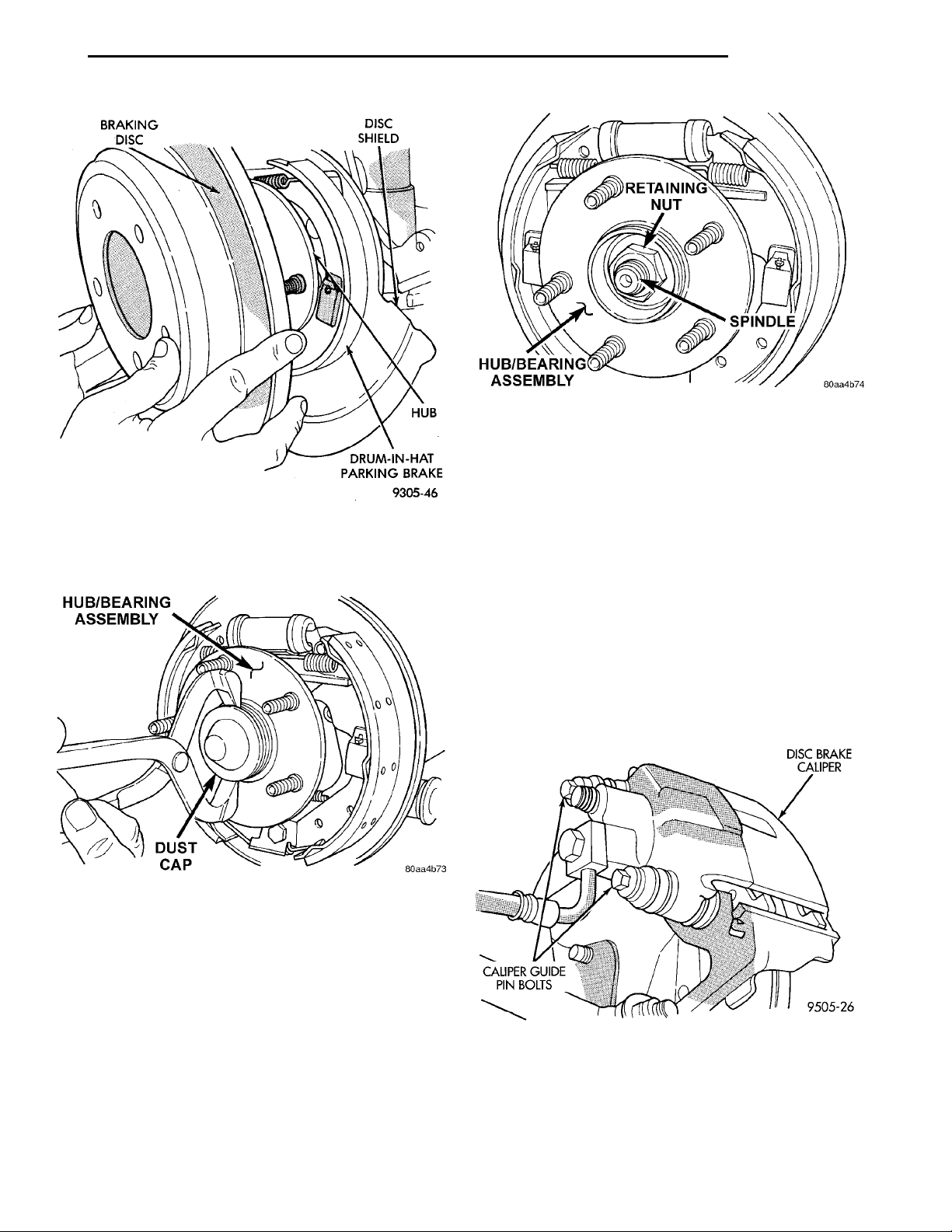
BRAKINGDISC DISCSHIELD HUBDRUM-IN-HAT PARKINGBRAKE
PL BRAKES 5 - 39
HUB/BEARING ASSEMBLYDUST CAP
RETAINING NUTSPINDLEHUB/BEARING ASSEMBLY
REMOVAL AND INSTALLATION (Continued)
DISC BRAKE CALIPERCALIPER GUIDE PINBOLTS
Fig. 99 Hub/Bearing Assembly Retaining Nut
(1) Position hub/bearing assembly on rear spindle.
(2) Install a new hub nut (Fig. 99) and tighten to
a torque of 217 N·m (160 ft. lbs.).
(3) Install the dust cap, on the hub/bearing using a
Fig. 97 Rear Rotor Removal
(4) Remove the dust cap (Fig. 98) from the rear
hub/bearing.
soft faced hammer.
(4) On drum brake equipped vehicles, install the
brake drum on the hub/bearing. On vehicles
equipped with rear disc brakes, install the rotor on
the hub/bearing.
(5) On disc brake equipped vehicles install the disc
brake caliper on the adapter. Install the 2 guide pin
bolts (Fig. 100) mounting the disc brake caliper to
the adapter. Tighten the guide pin bolts to a torque
of 22 N·m (192 in. lbs.). Refer To Rear Disc Brake
Service in this group of the service manual for the
required caliper installation procedure.
Fig. 98 Rear Hub/Bearing Dust Cap
(5) Remove the retaining nut (Fig. 99) mounting
the hub/bearing to the rear spindle.
(6) Remove the hub/bearing from the rear spindle
by pulling it off the end of spindle by hand.
INSTALL
CAUTION: The hub/bearing retaining nut must be
tightened to but must not exceed its required
torque specification. The proper torque specification of the retaining nut is critical to the life of the
hub bearing.
Fig. 100 Caliper Guide Pin Bolts
(6) Install rear wheel and tire assembly on vehicle.
Tighten all wheel stud nuts in criss cross pattern to
one-half specified torque. Then repeat pattern, fully
tightening stud nuts to 135 N·m (100 ft. lbs.).
(7) Lower vehicle.
Page 40
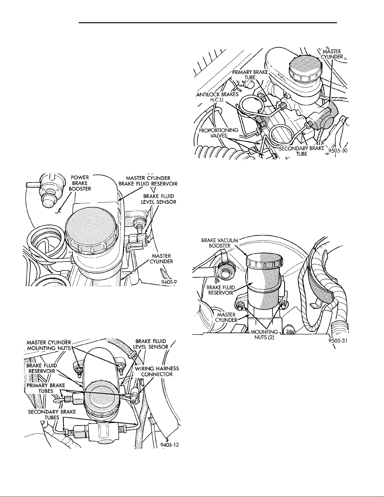
ANTILOCKBRAKESH.C.U.PRIMARY BRAKE TUBEMASTER CYLINDERPROPOR-TIONINGVALVESSECONDARYBRAKE TUBE
5 - 40 BRAKES PL
REMOVAL AND INSTALLATION (Continued)
MASTER CYLINDER
REMOVE
CAUTION: On ABS equipped vehicles, vacuum in
power booster must be pumped down before
removing master cylinder to prevent booster from
sucking in any contamination. This can be done
simply by pumping the brake pedal until a firm
MASTER CYLINDERMOUNTING NUTS BRAKE FLUID LEVELSENSORBRAKE FLUID RES-ERVOIRPRIMARY BRAKETUBESSECONDARY BRAKE TUBES WIRING HARNESS CON-NECTOR
pedal is achieved, with the ignition off.
(1) On ABS equipped vehicles, be sure engine is
not running, and pump the brake pedal until a firm
pedal is achieved (4-5 strokes).
(2) Remove vehicle wiring harness connector, from
brake fluid level sensor, in master cylinder brake
fluid reservoir (Fig. 101).
POWER BRAKEBOOSTER MASTER CYLINDER BRAKEFLUID RESERVOIRBRAKE FLUIDLEVEL SENSORMASTER CYLINDER
BRAKE VACUUMBOOSTERBRAKE FLUIDRESERVOIRMASTERCYL-INDER MOUNTINGNUTS (2)
Fig. 103 Primary And Secondary Brake Tubes With
ABS Brakes
(4) On vehicles equipped with ABS, clean area
where master cylinder attaches to booster using a
suitable brake cleaner product such as Mopar Brake
Parts Cleaner or an equivalent.
(5) Remove the 2 nuts (Fig. 104) attaching master
cylinder housing to power brake vacuum booster.
Fig. 101 Master Cylinder Fluid Level Sensor
(3) Disconnect the primary and secondary brake
tubes from the master cylinder (Fig. 102) and (Fig.
103). Install plugs at all open brake tube outlets on
master cylinder assembly.
Fig. 102 Primary And Secondary Brake Tubes W/O
ABS Brakes
Fig. 104 Master Cylinder Mounting To Vacuum
Booster
(6) Slide master cylinder assembly straight out of
the power brake vacuum booster.
CAUTION: On vehicles equipped with ABS, the
master cylinder is used to create the seal for holding vacuum in the power brake vacuum booster.
The vacuum seal in the front of the power brake
vacuum booster (Fig. 105) MUST be replaced whenever the master cylinder is removed from the power
brake vacuum booster.
(7) If vehicle is equipped with ABS, remove vacuum seal (Fig. 105) located in the front of the power
Page 41
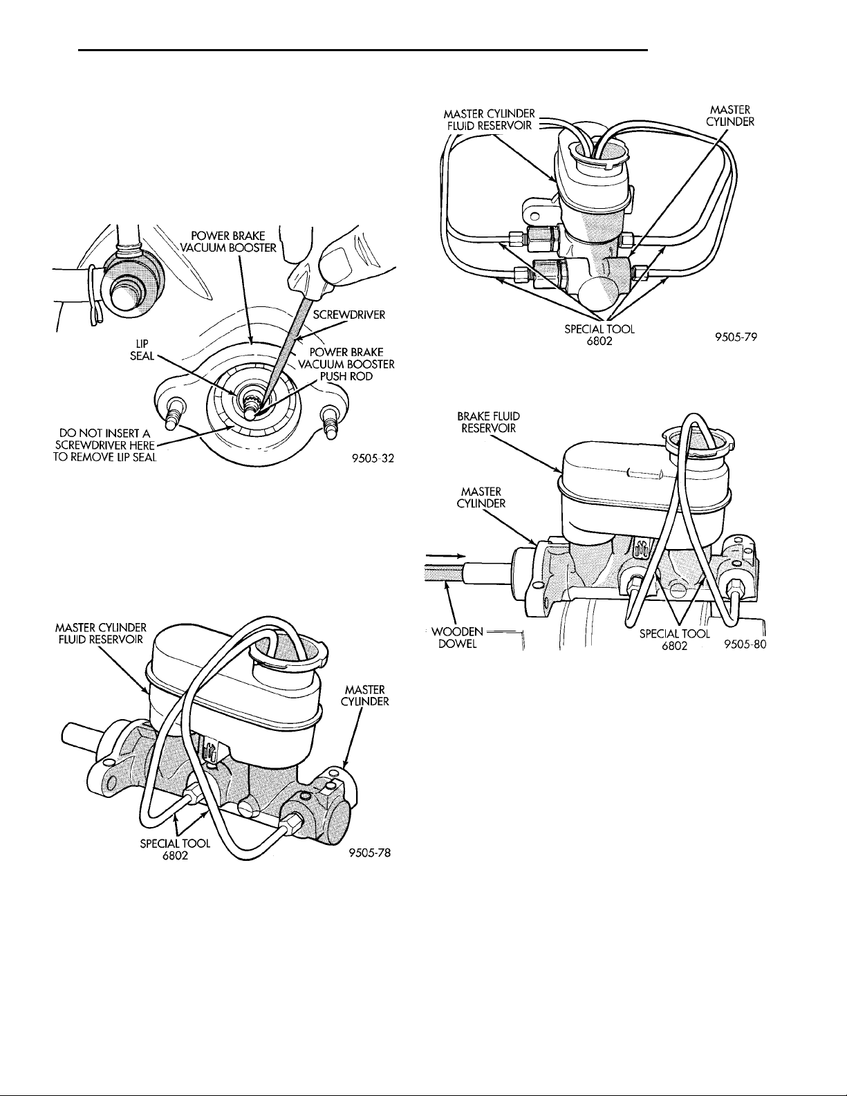
PL BRAKES 5 - 41
REMOVAL AND INSTALLATION (Continued)
brake vacuum booster. Vacuum seal is removed by
carefully inserting a small screw driver between the
push rod of the power brake vacuum booster and vacuum seal (Fig. 105) and pry seal out of power brake
vacuum booster. Do not attempt to pry seal out of
master cylinder by inserting a tool between
MASTER CYLINDERFLUID RESERVOIR MASTERCYLINDERSPECIAL TOOL 6802
seal and power brake vacuum booster.
POWER BRAKEVACUUM BOOSTER SCREW-DRIVERLIP SEALPOWER BRAKE VAC-UUM BOOSTER PUSHRODDO NOT INSERT ASCREWDRIVER HERETO REMOVE LIP SEAL
BRAKE FLUID RESERVOIRMASTER CYLINDERWOODENDOWEL SPECIAL TOOL 6802
Fig. 107 Bleeding Tubes Attached To Non-ABS
Master Cylinder
Fig. 105 Removing Seal From Vacuum Booster
BLEEDING MASTER CYLINDER
(1) Clamp the master cylinder in a vise. Attach
Bleeding Tubes, Special Tool 6802 to the master cylinder (Fig. 106) and (Fig. 107). Position tubes so outlets of Bleeding Tubes will be below surface of brake
fluid when reservoir is filled to proper level.
Fig. 106 Bleeding Tubes Attached to ABS Master
Cylinder
(2) Fill brake fluid reservoir with brake fluid conforming to DOT 3 specifications such as Mopar or an
Equivalent.
(3) Using a wooden dowel per (Fig. 108), depress
push rod slowly and then allow pistons to return to
released position. Repeat several times until all air
bubbles are expelled.
Fig. 108 Bleeding Master Cylinder
(4) Remove bleeding tubes from master cylinder
outlet ports, plug outlet ports and install fill cap on
reservoir.
(5) Remove master cylinder from vise.
NOTE: Note: It is not necessary to bleed the entire
hydraulic system after replacing the master cylinder. But the master cylinder must have been bled
and filled upon installation.
INSTALL
CAUTION: When replacing the master cylinder on
a vehicle equipped with ABS, a NEW vacuum seal
MUST be installed in the power brake vacuum
booster. Use only the procedure detailed below for
installing vacuum seal into power brake vacuum
booster. Be sure old vacuum seal is removed from
power brake vacuum booster before attempting to
install new seal.
Page 42
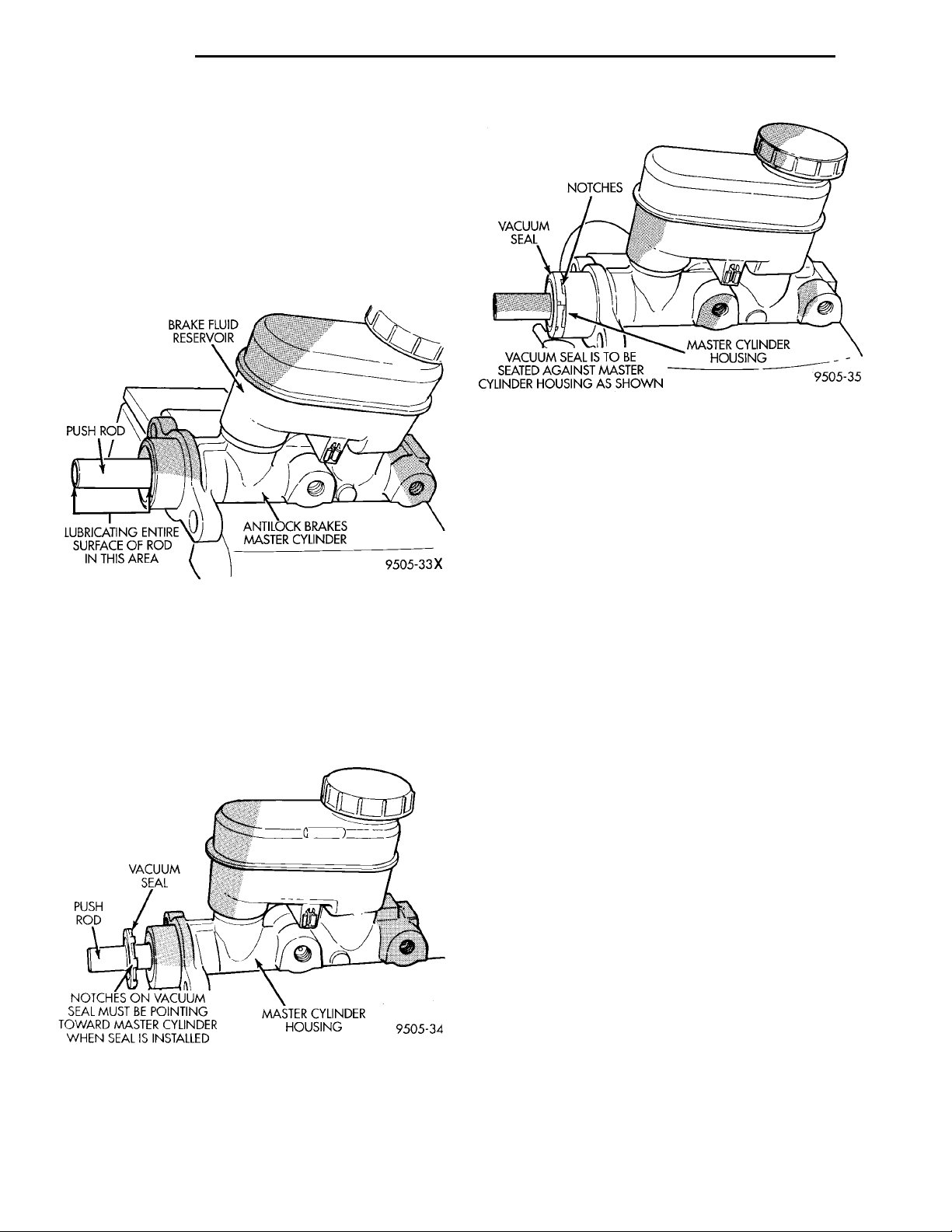
PUSH ROD VACUUMSEAL MASTER CYLINDER HOUSINGNOTCHES ON VACUUMSEAL MUST BE POINTINGTOWARD MASTER CYLIN-DER WHEN SEAL ISINSTALLED
BRAKE FLUID RESER-VOIRANTILOCKBRAKESMASTERCYLINDERLUBRICATING ENTIRESURFACE OF ROD INTHIS AREA PUSH ROD
NOTCHESVACUUM SEALVACUUM SEAL IS TO BE SEATEDAGAINST MASTER CYLINDER HOUS-ING AS SHOWN MASTER CYLINDERHOUSING
5 - 42 BRAKES PL
REMOVAL AND INSTALLATION (Continued)
CAUTION: When lubricating master cylinder push
rod, use only Mopar Silicone Dielectric Compound.
Using any other type of grease or lubricant on the
push rod, will not provide adequate long term lubrication of the push rod.
(1) Lubricate master cylinder push rod as indicated in (Fig. 109) only using Mopar Dielectric
Grease—And No Substitutes. Refer to the Mopar
Chemicals Catalog to obtain the required lubricant.
Fig. 111 Vacuum Seal Positioned For Installing
Master Cinder
CAUTION: If vehicle is equipped with ABS, be sure
old vacuum seal is removed from power brake vacuum booster before attempting to install master cylinder and NEW vacuum seal. If vacuum seal is not
removed, refer to Master Cylinder Removal in this
section of the service manual for required vacuum
seal removal procedure.
Fig. 109 Lubricating Master Cylinder Push Rod
(2) Install vacuum seal on master cylinder push
rod as shown in (Fig. 110) with notches on vacuum
seal pointing toward master cylinder housing. Then
slide vacuum seal onto master push rod until seal is
seated against master cylinder housing (Fig. 111)
before installing master cylinder on power brake vacuum booster.
(3) Position master cylinder on studs of power
brake unit, aligning push rod on power brake vacuum booster with master cylinder push rod.
(4) Install the 2 master cylinder to power brake
unit mounting nuts (Fig. 104) and torque to 28 N·m
(250 in. lbs.) torque.
(5) Connect brake tubes to master cylinder primary and secondary ports (Fig. 102) and (Fig. 103).
Torque all tube nuts to 17 N·m (145 in. lbs.) torque.
VACUUM BOOSTER
REMOVE
CAUTION: On ABS equipped vehicles, vacuum in
power booster must be pumped down before
removing master cylinder to prevent booster from
sucking in any contamination. This can be done
simply by pumping the brake pedal until a firm
pedal is achieved, with the ignition off.
(1) On ABS equipped vehicles, with engine not
running, pump the brake pedal until a firm pedal is
achieved (4-5 strokes).
Fig. 110 Installing Vacuum Seal On Master Cylinder
Push Rod
Page 43
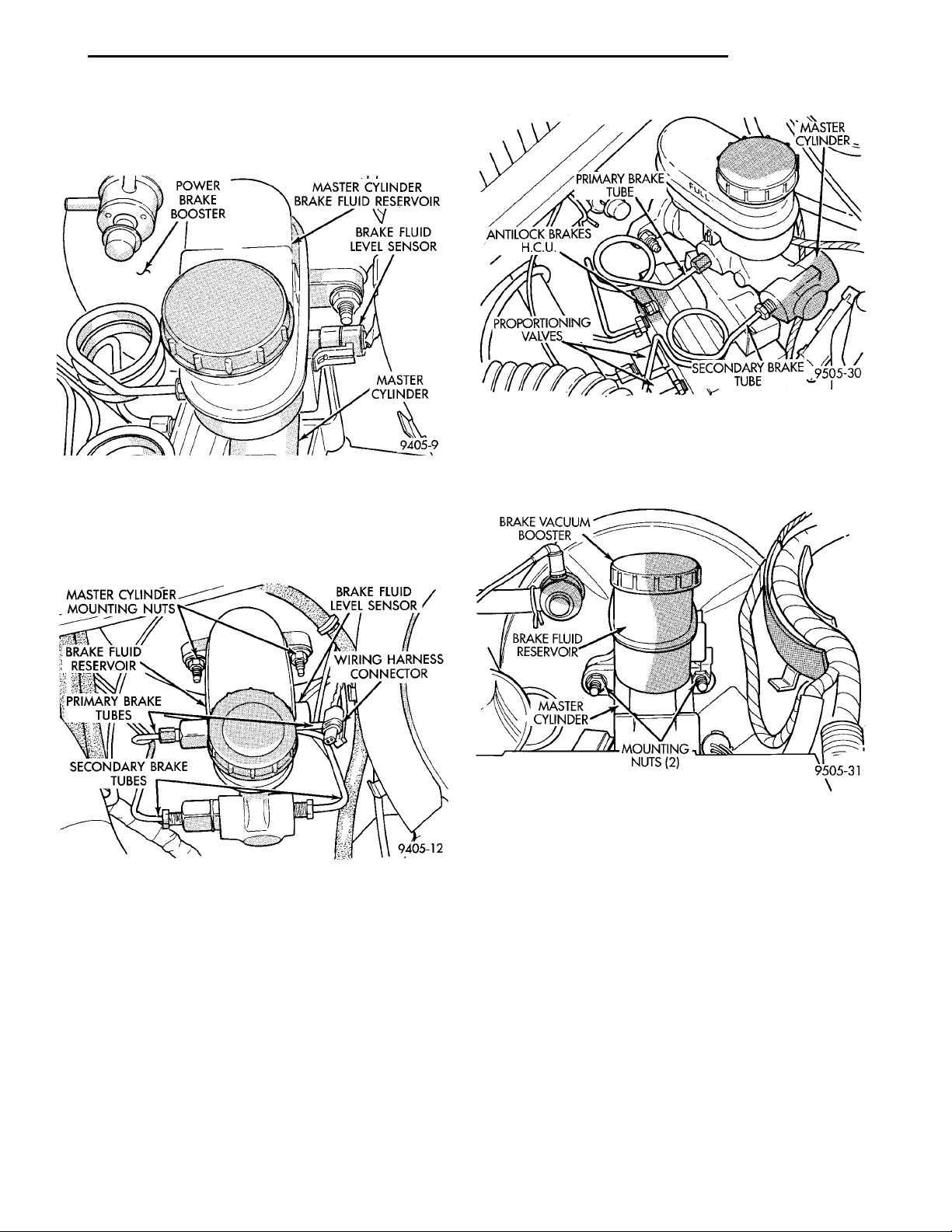
POWER BRAKEBOOSTER MASTER CYLINDER BRAKEFLUID RESERVOIRBRAKE FLUIDLEVEL SENSORMASTER CYLINDER
MASTER CYLINDERMOUNTING NUTS BRAKE FLUID LEVELSENSORBRAKE FLUID RES-ERVOIRPRIMARY BRAKETUBESSECONDARY BRAKE TUBES WIRING HARNESS CON-NECTOR
MASTERCYL-INDERPRIMARY BRAKE TUBEANTILOCK BRAKESH.C.U.PROPOR-TIONINGVALVESSECONDARYBRAKE TUBE
PL BRAKES 5 - 43
REMOVAL AND INSTALLATION (Continued)
(2) Remove vehicle wiring harness connector from
brake fluid level sensor located in master cylinder
brake fluid reservoir (Fig. 112).
Fig. 114 Primary And Secondary Brake Tubes With
ABS Brakes
Fig. 112 Master Cylinder Fluid Level Sensor
(3) Disconnect the primary and secondary brake
tubes from the master cylinder (Fig. 113) and (Fig.
114). Install plugs at all open brake tube outlets on
master cylinder assembly.
(5) Remove the 2 nuts (Fig. 115) attaching master
cylinder housing to power brake vacuum booster.
Fig. 113 Primary And Secondary Brake Tubes W/O
ABS Brakes
(4) On vehicles equipped with ABS, clean area
where master cylinder attaches to booster using a
suitable brake cleaner such as Mopar Brake Parts
Cleaner or an equivalent.
Fig. 115 Master Cylinder Mounting To Vacuum
Booster
(6) Slide master cylinder assembly straight out of
the power brake vacuum booster.
CAUTION: On vehicles equipped with ABS, the
master cylinder is used to create the seal for holding vacuum in the power brake vacuum booster.
The vacuum seal in the front of the power brake
vacuum booster (Fig. 116) MUST be replaced whenever the master cylinder is removed from the power
brake vacuum booster.
(7) If vehicle is equipped with ABS, remove vacuum seal (Fig. 116) located in the front of the power
brake vacuum booster. Vacuum seal is removed by
carefully inserting a small screw driver between the
push rod of the power brake vacuum booster and vacuum seal (Fig. 116) and prying seal out of power
Page 44
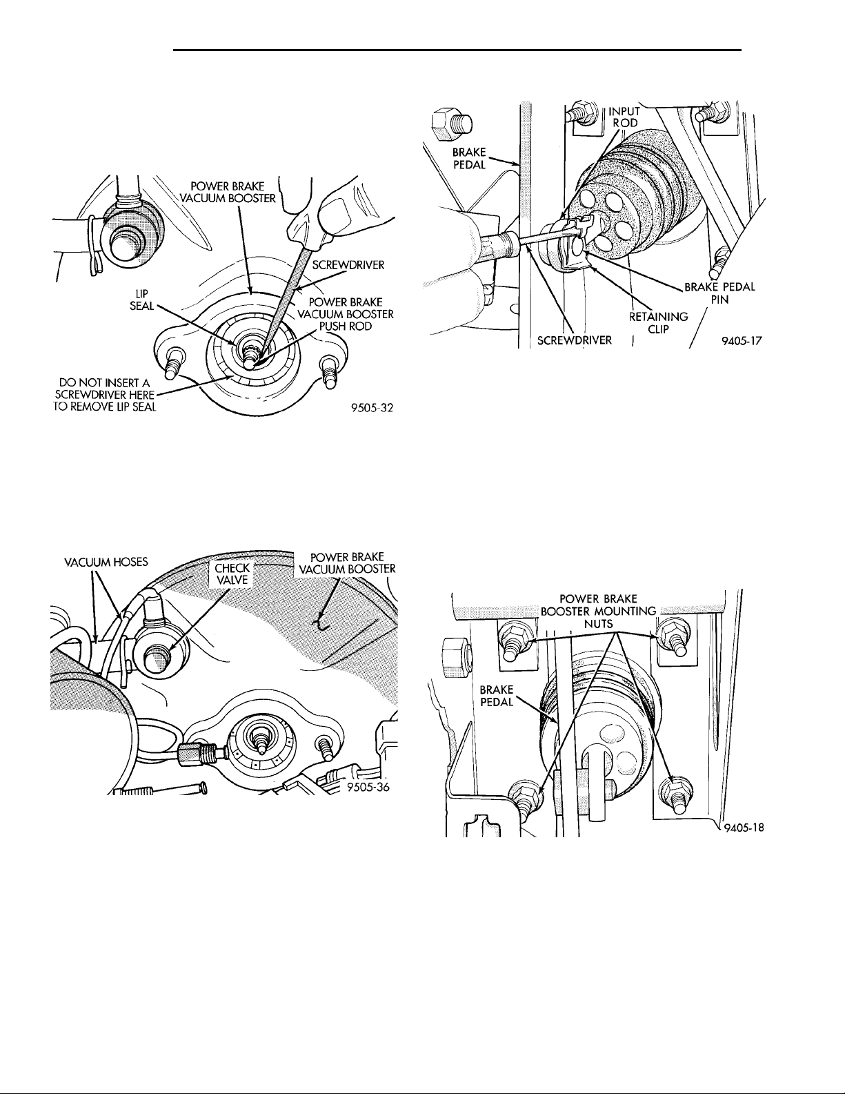
POWER BRAKEVACUUM BOOSTER SCREW-DRIVERLIP SEALPOWER BRAKE VAC-UUM BOOSTER PUSHRODDO NOT INSERT ASCREWDRIVER HERETO REMOVE LIP SEAL
VACUUM HOSES CHECKVALVE POWER BRAKE VAC-UUM BOOSTER
BRAKEPEDAL INPUTRODSCREWDRIVERRETAININGCLIPBRAKE PEDAL PIN
POWER BRAKEBOOSTER MOUNTINGNUTSBRAKEPEDAL
5 - 44 BRAKES PL
REMOVAL AND INSTALLATION (Continued)
brake vacuum booster. Do not attempt to pry seal
out of master cylinder by inserting a tool
between seal and power brake vacuum booster
.
Fig. 118 Input Rod Retaining Pin
CAUTION: Discard retaining clip when removed, it
is not to be reused. Replace only with a new retaining clip when assembled.
Fig. 116 Vacuum Seal Removal From Power Brake
Booster
(8) Disconnect vacuum hoses from check valve on
power brake vacuum booster (Fig. 117). Do not
remove check valve from power brake vacuum
booster.
(10) Rotate screwdriver (Fig. 118) enough to allow
retaining clip tang to pass over the end of the brake
pedal pin.
(11) Remove the 4 nuts attaching the power brake
vacuum booster to the dash panel (Fig. 119). The
nuts are accessible from under the instrument panel
in the area of the steering column and brake pedal
bracket.
Fig. 117 Power Brake Vacuum Booster Check Valve
NOTE: If vehicle is equipped with antilock brakes,
the hydraulic control unit (HCU) needs to be
removed from the vehicle to allow removal of the
power brake vacuum booster. Refer to Antilock
Brake System Hydraulic Control Unit in the
Removal And Installation Section of the Antilock
Brake System Section of this service manual for the
required procedure.
(9) Locate the power brake vacuum booster input
rod to brake pedal attachment under instrument
panel. Position a small screwdriver (Fig. 118) under
the center tang of the retaining clip.
Fig. 119 Power Brake Booster Mounting
(12) Slide power brake vacuum booster forward
until mounting studs clear dash panel, then tilt the
booster up and to the center of the vehicle to remove.
INSTALL
(1) Position power brake booster onto dash panel.
(2) Install and torque the 4 power brake vacuum
booster mounting nuts (Fig. 119) to 29 N·m (250 in.
lbs.) torque.
Page 45
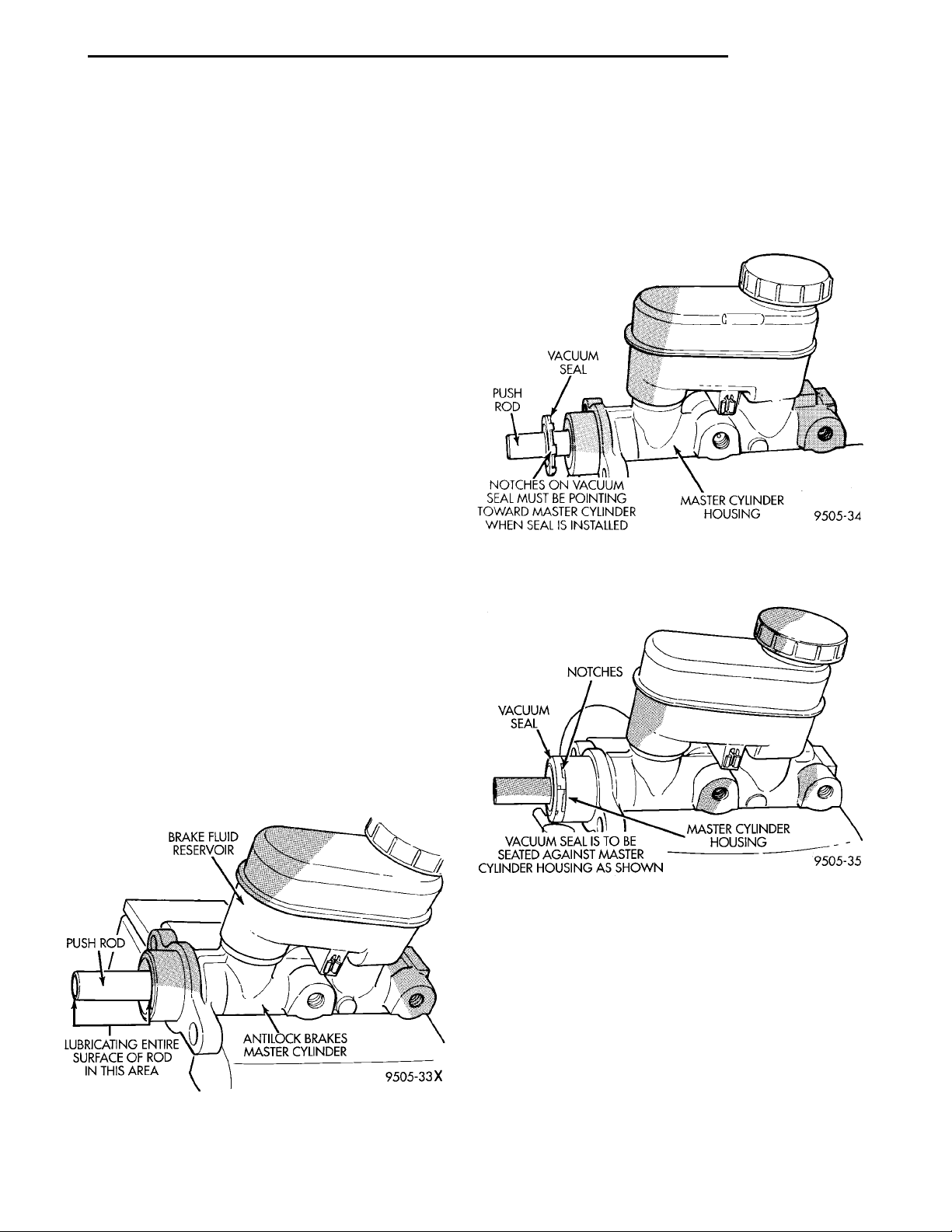
BRAKE FLUID RESER-VOIRPUSH RODLUBRICATING ENTIRESURFACE OF ROD INTHIS AREA ANTILOCK BRAKES MASTERCYLINDER
VACUUMSEAL PUSH ROD NOTCHES ON VACUUM SEAL MUSTBE POINTING TOWARD MASTERCYLINDER WHEN SEAL ISINSTALLEDMASTER CYLINDER HOUS-ING
NOTCHESVACUUM SEALVACUUM SEAL IS TO BE SEATEDAGAINST MASTER CYLINDER HOUS-ING AS SHOWN MASTER CYLINDERHOUSING
PL BRAKES 5 - 45
REMOVAL AND INSTALLATION (Continued)
(3) Using lubriplate, or equivalent, coat the surface of the brake pedal pin where it contacts the
brake vacuum booster input rod.
(4) Connect power brake vacuum booster input rod
to brake pedal pin and install a NEW retaining clip.
Use only a new retainer clip DO NOT USE the
old clip.
(5) Connect all previously removed vacuum hoses
onto power brake vacuum booster check valve (Fig.
117).
(6) If vehicle is equipped with ABS, install HCU.
Refer to Antilock Brake System Hydraulic Control
Unit in the Removal And Installation Section of the
Antilock Brake System Section of this service manual
for the required procedure.
CAUTION: When replacing the power brake vacuum booster on a vehicle equipped with ABS, a
NEW vacuum seal MUST be installed in the power
brake vacuum booster. Use only the procedure
detailed below for installing vacuum seal into power
brake vacuum booster. If old vacuum seal came out
with master cylinder when it was removed from
power brake vacuum booster, be sure it is removed
from master cylinder before attempting to install
master cylinder into power brake vacuum booster.
(8) Install vacuum seal on master cylinder push
rod as shown with notches on vacuum seal pointing
toward master cylinder housing (Fig. 121). Then slide
vacuum seal onto master push rod until seal is
seated against master cylinder housing (Fig. 122)
before installing master cylinder on power brake vacuum booster.
Fig. 121 Installing Vacuum Seal On Master Cylinder
Push Rod
CAUTION: When lubricating master cylinder push
rod, use only Mopar Silicone Dielectric Compound.
Using any other type of grease or lubricant on the
push rod, will not provide adequate long term lubrication of the push rod.
(7) Lubricate master cylinder push rod as indicated in (Fig. 120) only using Mopar Dielectric
Grease—And No Substitutes. Refer to the Mopar
Chemicals Catalog to obtain the required lubricant.
Fig. 122 Vacuum Seal Positioned For Installing
Master Cylinder
CAUTION: If vehicle is equipped with ABS, be sure
the old vacuum seal is removed from power brake
vacuum booster before attempting to install master
cylinder and NEW vacuum seal. If vacuum seal is
not removed, refer to Master Cylinder Removal in
this section of the service manual for required vacuum seal removal procedure.
Fig. 120 Lubricating Master Cylinder Push Rod
(9) Position master cylinder on studs of power
brake unit, aligning push rod on power brake vacuum booster with master cylinder push rod.
Page 46
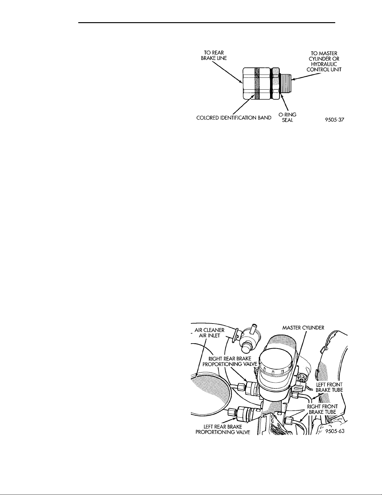
5 - 46 BRAKES PL
REMOVAL AND INSTALLATION (Continued)
(10) Install the 2 master cylinder mounting nuts
(Fig. 115) and torque to 28 N·m (250 in. lbs.) torque.
(11) Connect brake tubes to master cylinder primary and secondary ports (Fig. 113) and (Fig. 114).
Torque all tube nuts to 17 N·m (145 in. lbs.) torque.
(12) Reconnect wiring connector to fluid level sensor.
(13) Adjust stop lamp switch as necessary.
(14) Bleed brake system.
CHASSIS TUBES AND HOSES
Always use Mopar replacement brake hose assemblies to ensure quality, correct length and superior
fatigue life. Care should be taken to make sure that
the tube and hose mating surfaces are clean and free
from nicks and burrs. Hose assemblies for each
brake are unique and not interchangeable.
Use new copper seal washers on all connections
using Banjo Bolts and tighten all fittings to their
specified torques.
The flexible front hydraulic brake hose should
always be installed on the vehicle by first attaching
the Banjo connector to the caliper assembly. Then
bolt the intermediate hose bracket to the strut
assembly allowing the bracket to position the hose to
prevent twisting. Attach the hose to brake tubing,
before attaching to front frame rail. Then tighten all
brake line fittings to specified torque.
On vehicles equipped with rear drum brakes,
install rear brake hoses first to wheel cylinders and
rear struts and then attach hose bracket to body. On
vehicles equipped with rear disc brakes, attach brake
hoses to calipers and struts first and then attach
brake hose bracket to body. Following this procedure
will reduce potential for twisting brake during installation procedure.
Only double wall 4.75mm (3/16 in.) steel brake line
tubing, with Al- Rich/ZN-AL alloy coating should be
used for replacement. Care must be taken when
replacing brake tubing, to be sure the proper bending
and flaring tools and procedures are used to avoid
kinking. Do not route the tubes against sharp edges,
moving components or into hot areas. All tubes
should be properly attached with recommended
retaining clips.
If premature rear wheel skid occurs on hard brake
application, it could be an indication that a malfunction has occurred with one of the proportioning
valves.
One proportioning valve controls the right rear
brake, and the other proportioning valve controls the
left rear brake (Fig. 124). Therefore, a road test to
determine which rear brake slides first is essential.
If a malfunctioning proportioning valve is suspected on a vehicle. Refer to Brake Hydraulic System
Control Valves in the Diagnosis And Testing Section
in this group of the service manual for the required
test procedure.
REMOVE
Use the proportioning valve test procedure stated
above to determine which proportioning valve
requires replacement, then replace it using procedure
below.
AIR CLEANERAIR INLET MASTER CYLINDER
LEFT REAR BRAKE PROPOR-TIONING VALVE
(1) Disconnect brake tube from proportioning valve
RIGHT REAR BRAKE PROPOR-
requiring removal from the master cylinder (Fig.
124).
(2) Remove proportioning valve (Fig. 124) from the
master cylinder requiring replacement.
Fig. 123 Proportioning Valve
TIONING VALVE
RIGHT FRONT
LEFT FRONT BRAKE
BRAKE TUBE
TUBE
PROPORTIONING VALVE (BASE BRAKES)
CAUTION: Proportioning valves (Fig. 123) should
never be disassembled.
There are two proportioning valve assemblies used
in each vehicle. Due to different thread sizes, each
proportioning valve has a different part number. During any service procedures identify the proportioning
valve assemblies by supplier part number and or the
color identification band (Fig. 123).
Fig. 124 Non-ABS Proportioning Valve Locations On
Master Cylinder
Page 47
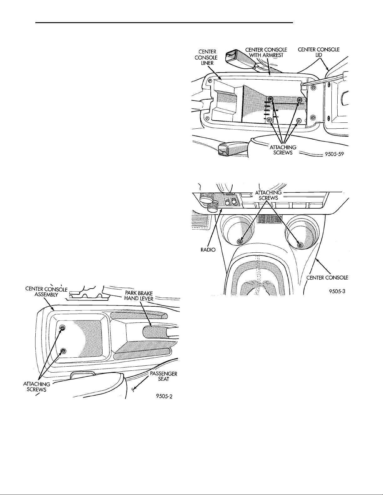
PL BRAKES 5 - 47
REMOVAL AND INSTALLATION (Continued)
INSTALL
(1) Wet O-ring seal on new proportioning valve
using clean fresh brake fluid.
(2) Install proportioning valve in master cylinder
and hand tighten until proportioning valve and
O-ring seal is fully seated in master cylinder. Torque
proportioning valve to 40 N·m (30 ft. lbs.).
(3) Install brake tube on proportioning valve.
Tighten tube nut to 17 N·m (145 in lbs.) torque.
(4) Bleed the affected brake line. See Bleeding
Base Brake Hydraulic System in the Service Procedures Section in this group of the service manual for
the proper bleeding procedure.
PARK BRAKE LEVER ASSEMBLY
WARNING: THE AUTO ADJUSTING FEATURE OF
THIS PARKING BRAKE LEVER ASSEMBLY CONTAINS A CLOCK SPRING LOADED TO APPROXIMATELY 20 POUNDS. DO NOT RELEASE THE AUTO
ADJUSTER LOCKOUT DEVICE BEFORE INSTALLING CABLES INTO THE EQUALIZER. KEEP HANDS
OUT OF AUTO ADJUSTER SECTOR AND PAWL
AREA. FAILURE TO OBSERVE CAUTION IN HANDLING THIS MECHANISM COULD LEAD TO SERIOUS INJURY.
CENTER CONSOLEASSEMBLY PARK BRAKEHAND LEVERATTACHINGSCREWS PAS-SENGERSEAT
REMOVE
(1) Remove the screws attaching the rear of the
center console assembly to console bracket (Fig. 125)
or (Fig. 126).
Fig. 126 Center Console Rear Attaching Screws
With Arm Rest
Fig. 127 Attaching Screws At Front Of Center
Console
(4) Remove center console assembly.
WARNING: WHEN REPAIRS TO THE PARK BRAKE
HAND LEVER ASSEMBLY OR CABLES IS
REQUIRED, THE AUTO ADJUSTER MUST BE
RELOADED AND LOCKED OUT.
Fig. 125 Center Console Rear Attaching Screws W/O
Arm Rest
(2) Remove the 2 screws located in cup holders
(Fig. 127), attaching front of center console assembly
to console bracket.
(3) Raise park brake hand lever as high as it will
go to get the required clearance to remove the center
console.
(5) Lower park brake lever handle.
(6) Grasp park brake lever output cable by hand
and pull rearward (Fig. 128). Continue pulling on
cable until a 3/16 in. drill bit can be inserted into
handle and sector gear of park brake mechanism
(Fig. 128). This will lock the park brake mechanism
and take tension off park brake cables.
(7) Remove both rear park brake cables from the
park brake cable equalizer (Fig. 129).
(8) Remove wiring harness electrical connector for
brake warning light ground from the park brake
lever (Fig. 130).
Page 48
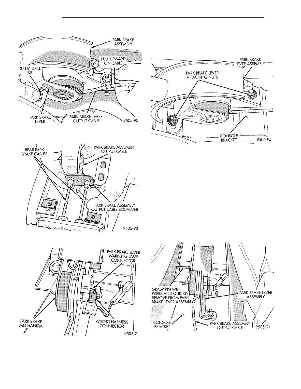
5 - 48 BRAKES PL
REMOVAL AND INSTALLATION (Continued)
(9) Remove the 2 nuts (Fig. 131) attaching the
park brake lever to the console bracket. Remove park
brake lever mechanism from vehicle.
Fig. 128 Locking Pin Installed In Park Brake
Mechanism
Fig. 131 Park Brake Lever Attachment To Console
Bracket
INSTALL
(1) Place park brake lever on console bracket.
Install and securely tighten the 2 attaching nuts
(Fig. 131).
(2) Install both rear park brake cables into equalizer on park brake lever output cable (Fig. 129).
(3) Ensure that park brake cable is correctly
installed and aligned with cable track on park brake
CONSOLEBRACKET
PARK BRAKE LEVERWARNING LAMPCONNECTORWIRING HARNESS CONNEC-TORPARK BRAKE MECHANISM
Fig. 129 Park Brake Cables At Equalizer
lever.
GRASP PIN WITH PLIERS
AND QUICKLY REMOVE
(4) Firmly grasp park brake lever locking pin (Fig.
FROM PARK BRAKE
LEVER ASSEMBLY
132) and quickly remove it from the park brake lever
mechanism. This will allow the park brake lever
mechanism to correctly adjust the park brake cables.
PARK BRAKE ASSEMBLY
PARK BRAKE LEVER
OUTPUT CABLE
ASSEMBLY
Fig. 130 Brake Warning Lamp Connection To Park
Brake Lever
Fig. 132 Removing Lockout Pin From Park Brake
Lever Assembly
(5) Connect electrical connector for brake warning
lamp onto terminal on park brake lever assembly
(Fig. 130).
Page 49
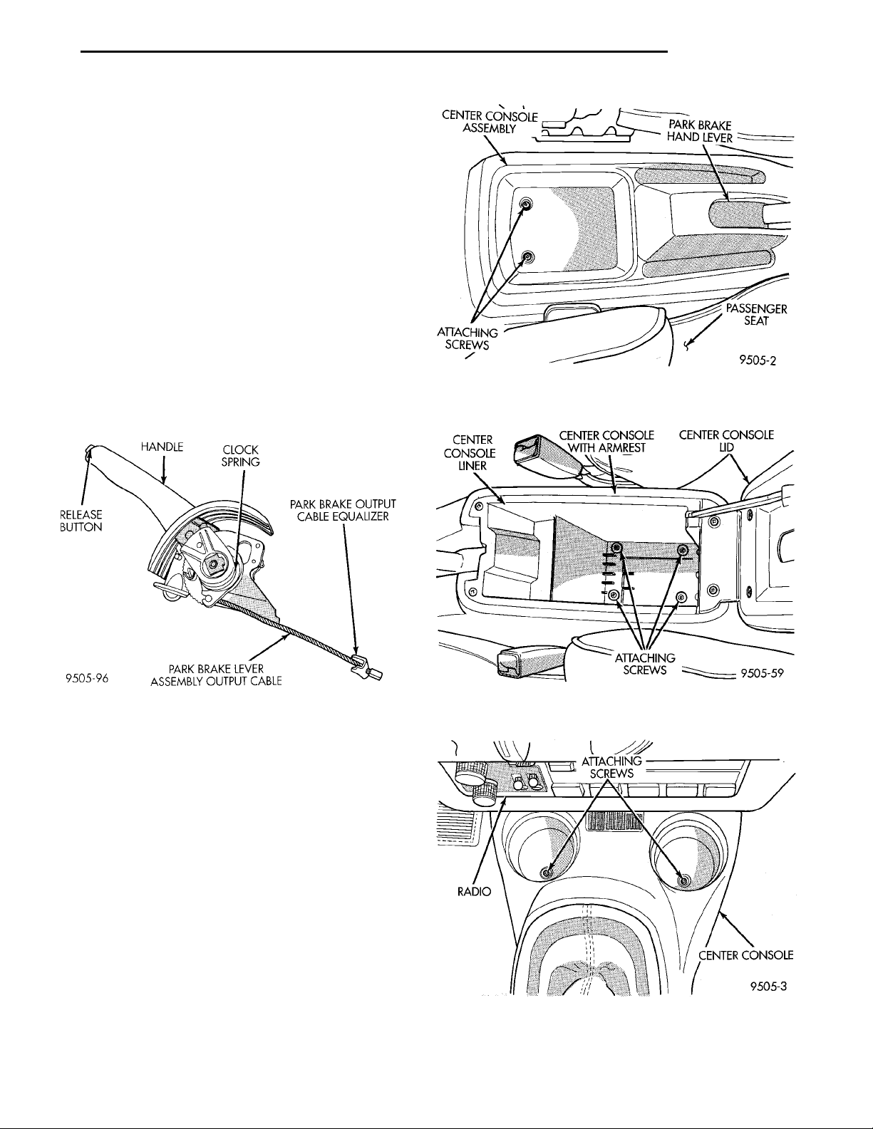
HANDLE CLOCK SPRINGPARK BRAKE OUTPUTCABLE EQUALIZERPARK BRAKE LEVERASSEMBLY OUTPUT CABLERELEASE BUTTON
CENTER CONSOLEASSEMBLY PARK BRAKEHAND LEVERATTACHINGSCREWS PAS-SENGERSEAT
CENTER CON-SOLE LINER CENTER CONSOLE WITHARMREST CENTER CONSOLELIDATTACHINGSCREWS
PL BRAKES 5 - 49
REMOVAL AND INSTALLATION (Continued)
(6) Cycle park brake lever once to position park
brake cables. Then return the park brake lever its
released position. Check the rear wheels of the vehicle. They should rotate freely without dragging.
(7) Raise park brake lever to its fully engaged
position. This is necessary to allow installation of the
center console.
(8) Install center console assembly.
(9) Install the 4 center console assembly attaching
screws (Fig. 125), (Fig. 126) and (Fig. 127).
PARK BRAKE LEVER OUTPUT CABLE
On this vehicle, the park brake lever output cable
(Fig. 133), is not replaceable as a separate component
of the park brake lever. The park brake lever output
cable (Fig. 133) should never be attempted to be
repaired in any manner. Follow the require procedures under park brake lever removal and replacement when servicing a park brake lever output cable.
Fig. 134 Center Console W/O Arm Rest Rear
Attaching Screws
Fig. 133 Brake Lever Assembly And Output Cable
PARK BRAKE CABLES
NOTE: Note: Remove only one rear park brake
cable from rear brakes at a time. Failure to do so
will result in high efforts required to connect park
brake cables to equalizer or park brake lever at rear
wheel brakes.
For installation of the rear park brake cables follow the procedure as listed below.
REMOVE
(1) Remove screws attaching rear of center console
assembly to floor pan of vehicle (Fig. 134) or (Fig.
135).
(2) Remove the 2 screws located in cup holders
(Fig. 136) attaching front of center console to console
bracket.
(3) Raise park brake lever as high as it will go for
the clearance required to remove the center console.
ATTACHINGSCREWS CENTER CON-SOLERADIO
Fig. 135 Center Console With Arm Rest Rear
Attaching Screws
Fig. 136 Center Console Front Attaching Screws
(4) Remove center console assembly from vehicle.
Page 50
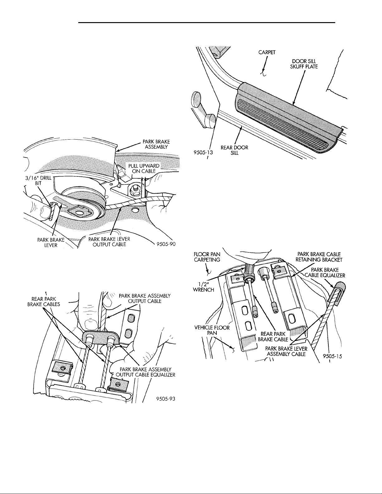
5 - 50 BRAKES PL
REMOVAL AND INSTALLATION (Continued)
WARNING: WHEN REPAIRS TO THE PARK BRAKE
HAND LEVER ASSEMBLY OR CABLES IS
REQUIRED, THE AUTO ADJUSTER MUST BE
RELOADED AND LOCKED OUT.
(5) Lower park brake lever handle.
(6) Grasp park lever output cable by hand and pull
rearward (Fig. 137). Continue pulling on cable until a
3/16 in. drill bit can be inserted into handle and sector gear of park brake mechanism (Fig. 137). This
will lock the park brake mechanism and take tension
off park brake cables.
Fig. 139 Rear Door Sill Scuff Plates
(10) Fold rear carpeting forward to expose park
brake cables.
(11) Install the box end of a 1/2 in. wrench over
the park brake cable retainer as indicated in (Fig.
VEHICLE FLOORPAN1/ 2” WRENCHFLOOR PANCARPETING
140). This will compress tabs on park brake cable
REAR PARK BRAKE
retainer, allowing cable to be removed from console
bracket. From under carpet, grasp park brake cable
housing and pull cable straight out of console
bracket.
PARK BRAKE CABLERETAINING BRACKETPARK BRAKE CABLEEQUALIZERPARK BRAKE LEVERASSEMBLY CABLE
CABLE
REAR PARK BRAKECABLES PARK BRAKE ASSEMBLYOUTPUT CABLEPARK BRAKE ASSEMBLY OUTPUTCABLE EQUALIZER
Fig. 137 Locking Pin Installed In Park Brake
Mechanism
(7) Remove rear park brake cables from the park
brake cable equalizer (Fig. 138).
Fig. 138 Park Brake Cables Attachment To Equalizer
(8) Remove rear seat cushion from vehicle.
(9) Remove scuff plates (Fig. 139) from right and
left rear door sills. Scuff plates are attached to door
sills using clips on bottom of scuff plates. Remove by
carefully prying scuff plate retaining clips out of
door sills.
Fig. 140 Compressing Park Brake Cable Retaining
Tabs
(12) Raise vehicle on jackstands or centered on a
frame contact type hoist. See Hoisting in the Lubrication and Maintenance section of this manual for
the required lifting procedure to be used for this
vehicle.
(13) Remove rear wheel and tire assembly.
(14) On vehicles equipped with rear drum brakes,
remove brake drum (Fig. 141) from rear hub/bearing
assembly. On vehicles equipped with rear disc
brakes, remove disc brake caliper from disc brake
Page 51
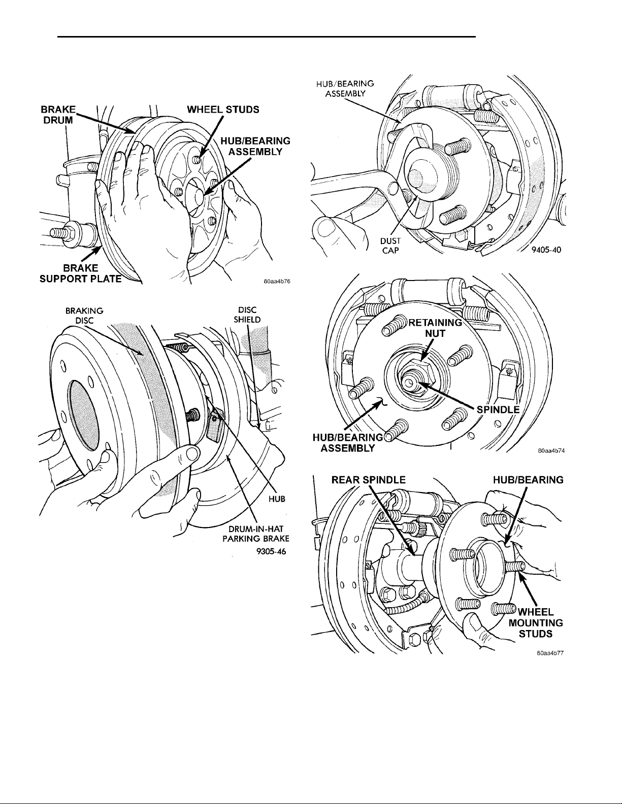
REAR SPINDLEHUB/BEARINGWHEEL MOUNTING STUDS
BRAKE DRUMWHEEL STUDSHUB/BEARING ASSEMBLYBRAKE SUPPORT PLATE
BRAKINGDISC DISCSHIELD HUBDRUM-IN-HAT PARKINGBRAKE
HUB/BEARINGASSEMBLY DUST CAP
RETAINING NUTSPINDLEHUB/BEARING ASSEMBLY
PL BRAKES 5 - 51
REMOVAL AND INSTALLATION (Continued)
adapter, and then remove rotor (Fig. 142) from hub/
bearing assembly.
Fig. 143 Dust Cap Removal
Fig. 141 Brake Drum Removal
Fig. 142 Rear Brake Rotor
(15) Remove the dust dust cap (Fig. 143) from the
rear hub/bearing.
(16) Remove the retaining nut (Fig. 144) for the
hub/bearing from the spindle.
(17) Remove thehub/bearing (Fig. 145) from the
rear spindle.
(18) On vehicles equipped with rear drum
brakes, remove park brake cable from park brake
actuating lever (Fig. 146). Then remove the actuating
spring (Fig. 147) between brake shoe adjustment
lever and brake shoe assembly.
Fig. 144 Hub/Bearing Retaining Nut
Fig. 145 Hub/Bearing Removal From Spindle (Drum
Brakes Shown)
(19) On vehicles equipped with rear disc
brakes, remove brake shoe assemblies (Fig. 148)
from rear disc brake adapter. Then remove parking
brake actuating lever (Fig. 149) from the park brake
cable.
Page 52
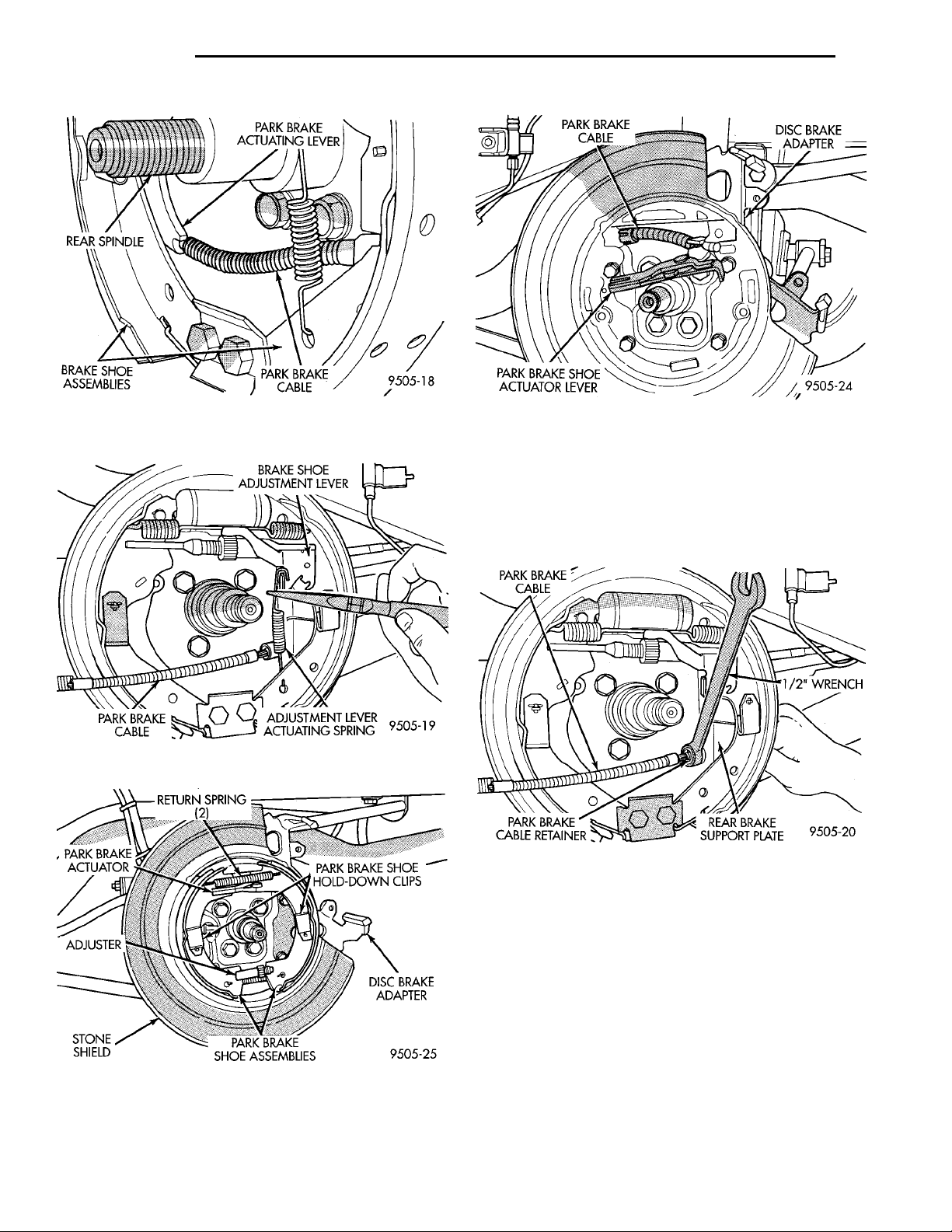
BRAKE SHOE ASSEM-BLIES
PARK BRAKE ACTUA-
REAR SPINDLE
TOR
RETURN SPRING(2) PARK BRAKE SHOEHOLD-DOWN CLIPSDISC BRAKEADAPTERPARK BRAKE SHOE ASSEM-BLIESSTONE SHIELDADJUSTER
PARK BRAKE ACTUAT-ING LEVER
BRAKE SHOE ADJUST-MENT LEVERADJUSTMENT LEVERACTUATING SPRINGPARK BRAKE CABLE
PARK BRAKE
CABLE
PARK BRAKE CABLE 1/2” WRENCH
PARK BRAKE CABLE
REAR BRAKE SUP-PORT PLATEPARK BRAKE CABLERETAINER
DISC BRAKEADAPTERPARK BRAKE SHOEACTUATOR LEVER
5 - 52 BRAKES PL
REMOVAL AND INSTALLATION (Continued)
Fig. 146 Park Brake Cable Attachment To Actuating
Lever
Fig. 147 Brake Adjustment Lever Actuating Spring
Fig. 149 Parking Brake Actuator Lever
(20) On vehicles equipped with rear drum brakes,
remove park brake cable (Fig. 150) from rear brake
support plate. Park brake cable is removed from
brake support plate using a 1/2 in. wrench as shown
in (Fig. 150) to compress locking tabs on park brake
cable retainer.
Fig. 150 Park Brake Cable Removal From Brake
Support Plate
Fig. 148 Parking Brake Shoe Assemblies
Page 53
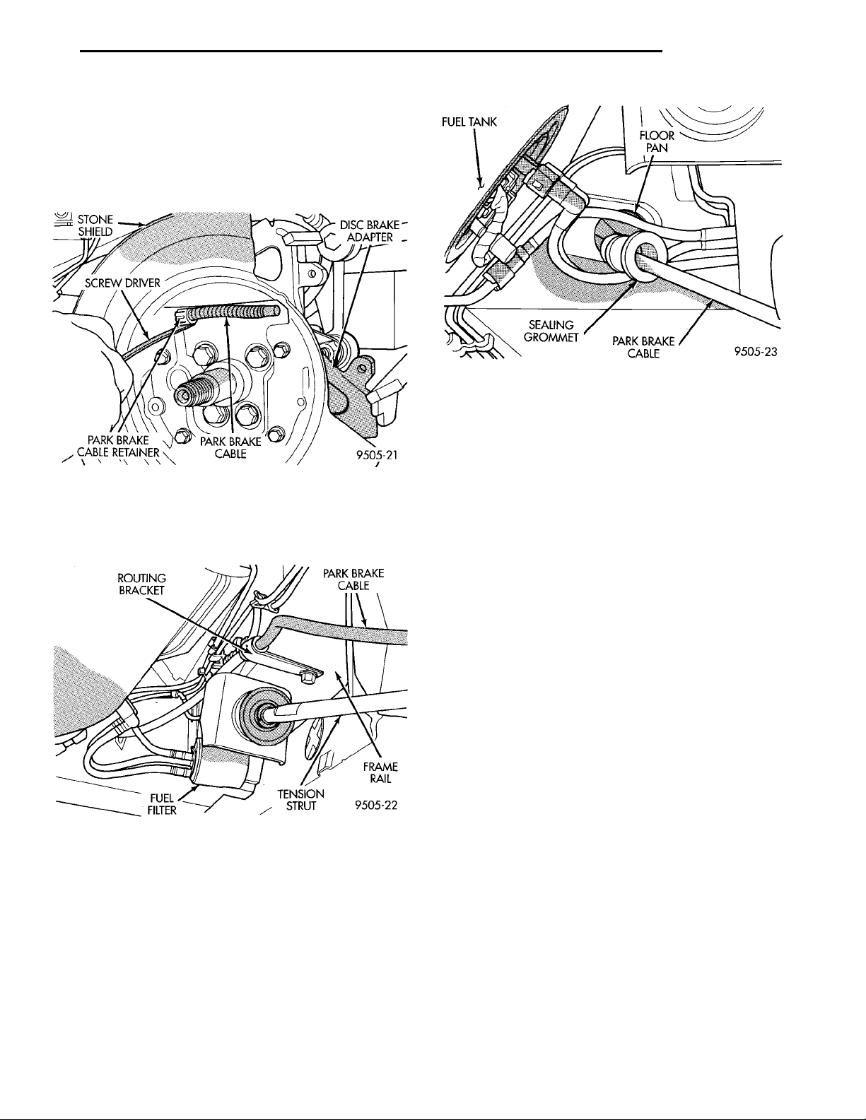
ROUTING BRACKET
STONE SHIELD
DISC BRAKEADAPTERPARK BRAKECABLEPARK BRAKE CABLERETAINERSCREW DRIVER
FRAME RAILTENSION STRUTFUEL FILTER
PARK BRAKE CABLE
FUEL TANK FLOOR PANPARK BRAKE CABLESEALING GROM-MET
PL BRAKES 5 - 53
REMOVAL AND INSTALLATION (Continued)
(21) On vehicles equipped with rear disc brakes,
remove park brake cable (Fig. 151) from rear disc
brake adapter. Park brake cable is removed from disc
brake adapter using a screwdriver as shown in (Fig.
151) to compress locking tabs on park brake cable
retainer.
Fig. 153 Park Brake Cable Seal At Floor Pan
(3) Install park brake cable routing bracket (Fig.
152) on frame rail. Install and securely tighten routing bracket attaching bolt.
(4) On vehicles equipped with rear drum
brakes, install park brake cable on park brake cable
Fig. 151 Park Brake Cable Removal From Disc
Brake Adapter
(22) Remove park brake cable routing bracket (Fig.
152) from vehicle frame rail.
Fig. 152 Park Brake Cable Routing Bracket
(23) Remove park brake cable and sealing grommet (Fig. 153) from floor pan of vehicle.
INSTALL
(1) Install park brake cable into floor pan of vehicle making sure sealing grommet is installed in floor
pan as far as possible to insure proper seal.
(2) Install park brake cable into brake support
plate or rear disc brake adapter. Be sure locking tabs
on cable retainer are expanded to ensure park brake
cable is securely held in support plate or adapter.
actuating lever (Fig. 146). Then install actuating
spring between brake shoe assembly and brake
adjustment lever (Fig. 147).
(5) On vehicles equipped with rear disc
brakes, install park brake shoes actuator lever (Fig.
149) on park brake cable. Then install park brake
shoe assemblies on disc brake adapter (Fig. 148).
(6) Install the hub/bearing assembly on the rear
spindle. Then install A NEW rear hub/bearing
assembly retaining nut. Torque hub/bearing assembly
retaining nut to 217 N·m (160 ft. lbs.).
(7) Install hub/bearing assembly dust cap, using a
soft faced hammer.
(8) On drum brake equipped vehicles, install rear
brake drum on hub/bearing assembly. On vehicles
equipped with rear disc brakes, install rotor on hub/
bearing assembly.
(9) On disc brake equipped vehicles install disc
brake caliper on disc brake adapter. Install the 2 caliper guide pin bolts (Fig. 154) and torque to 22 N·m
(192 in. lbs.). Refer To Rear Disc Brake Service in
this group of the service manual for the required caliper installation procedure.
(10) Install rear wheel and tire assembly on vehicle. Tighten all wheel stud nuts in criss cross pattern
to one-half specified torque. Then repeat pattern,
fully tightening stud nuts to 135 N·m (100 ft. lbs.).
(11) Lower vehicle.
(12) Grasp park brake cable to floor pan seal
grommet (Fig. 155) by hand, and pull it into floor
pan to ensure seal grommet is fully seated into floor
pan.
(13) Route park brake cable under carpeting and
up to park brake cable retaining bracket on floor
Page 54
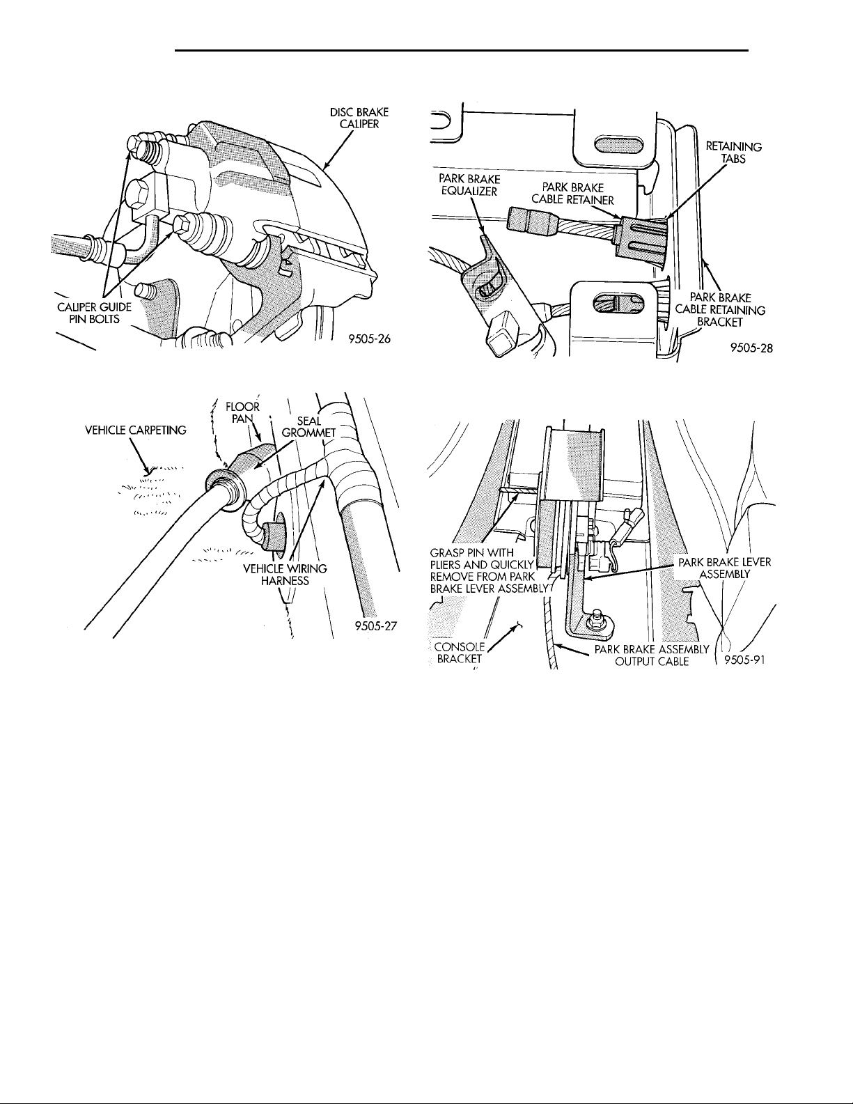
VEHICLE CARPETING FLOOR PAN SEAL GROM-METVEHICLE WIRING HARNESS
DISC BRAKE CALIPERCALIPER GUIDE PINBOLTS
5 - 54 BRAKES PL
REMOVAL AND INSTALLATION (Continued)
Fig. 154 Rear Caliper Guide Pin Bolts
CONSOLEBRACKET
PARK BRAKE ASSEMBLY
OUTPUT CABLE
PARK BRAKE LEVER ASSEM-
GRASP PIN WITH PLIERS
AND QUICKLY REMOVE
BLY
FROM PARK BRAKE
LEVER ASSEMBLY
Fig. 156 Park Brake Cable Installed In Retaining
Bracket
Fig. 155 Seal Grommet Installation In Floor Pan
pan. Then install park brake cable into retaining
bracket (Fig. 156). Be sure tabs (Fig. 156) on park
brake cable retainer, have expanded out to hold park
brake cable in retaining bracket.
(14) Install rear park brake cables into equalizer
(Fig. 138) on park brake lever cable.
(15) Reposition rear carpeting.
(16) Install both rear door sill plate scuff moldings,
by snapping them onto rear door sills.
(17) Install lower rear seat cushion. Be sure lower
seat cushion is fully installed in retainers on floor
pan of vehicle.
(18) Firmly grasp park brake lever locking pin
(3/16 in. drill bit) (Fig. 157) and quickly remove it
from the park brake lever mechanism. This will
allow the park brake lever mechanism to correctly
adjust the park brake cables.
(19) Cycle park brake lever ounce to position park
brake cables. Then return the park brake lever its
released position. Check the rear wheels of the vehicle, they should rotate freely without dragging.
(20) Apply park brake to full engagement.
Fig. 157 Removing Lockout Pin From Park Brake
Lever
(21) Install center console assembly.
(22) Install the center console assembly attaching
screws.
PARK BRAKE SHOES WITH REAR DISC BRAKES
REMOVE
(1) Remove rear disc brake caliper assembly from
adapter and rotor (See Disc Brake Shoe Removal).
(2) Remove rear rotor from rear hub.
(3) Remove dust cap from rear hub.
(4) Remove rear hub and bearing assembly retain-
ing nut and washer.
(5) Remove rear hub and bearing assembly from
rear spindle.
(6) Remove rear brake shoe assembly hold down
clip (Fig. 158).
(7) Turn brake shoe adjuster wheel until adjuster
is at shortest length.
Page 55
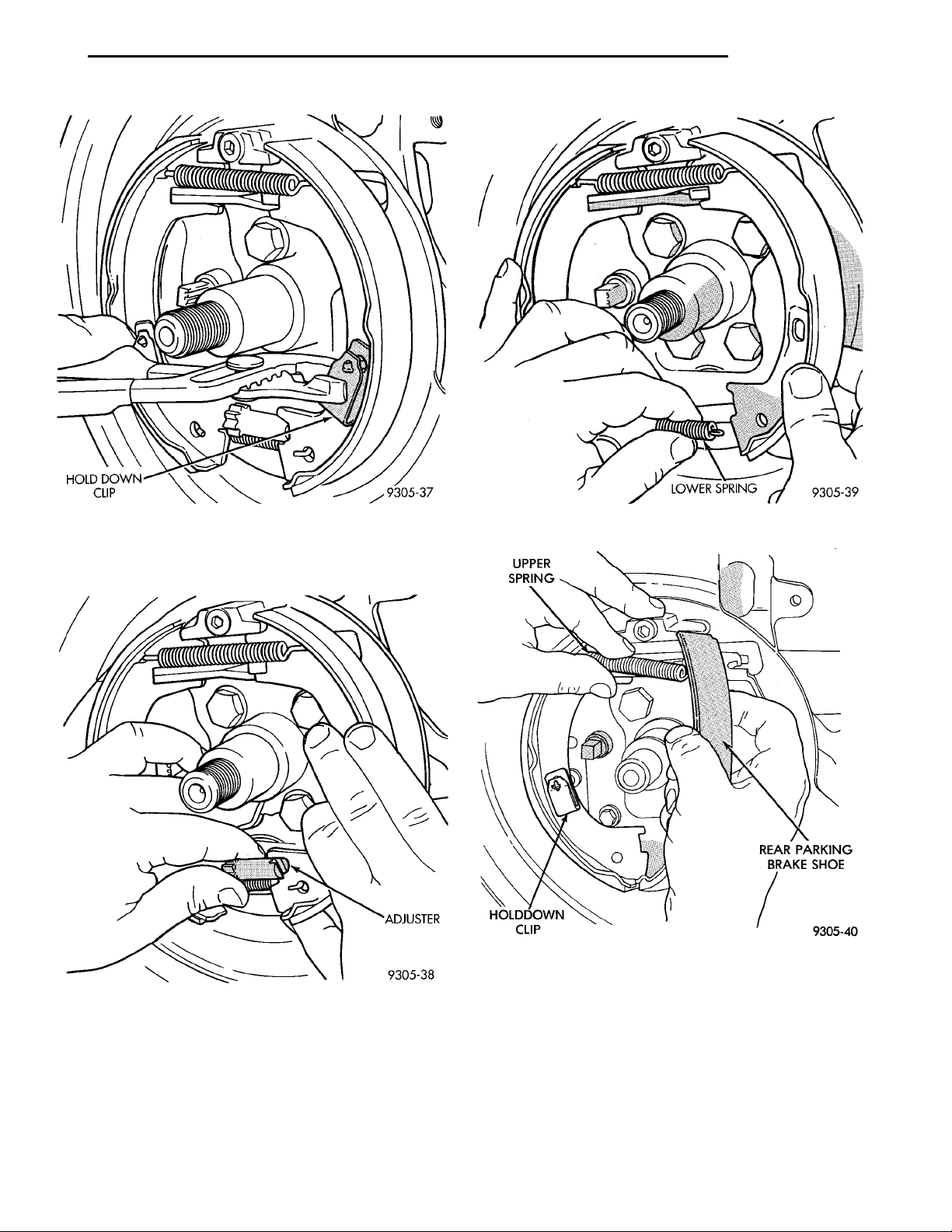
HOLD DOWNCLIP
UPPERSPRINGREAR PARK-ING BRAKESHOE HOLDDOWN CLIP
LOWERSPRING
PL BRAKES 5 - 55
ADJUSTER
REMOVAL AND INSTALLATION (Continued)
Fig. 158 Rear Brake Shoe Hold-Down Clip
(8) Remove adjuster assembly from the parking
brake shoe assemblies (Fig. 159).
Fig. 159 Park Brake Shoe Adjuster Assembly
(9) Remove lower shoe to shoe spring (Fig. 160).
(10) Pull rear brake shoe assembly away from
anchor. Then remove rear brake shoe and upper
spring (Fig. 161).
(11) Remove front brake shoe hold-down clip (Fig.
162). Then remove front brake shoe assembly.
Fig. 160 Brake Shoe Lower Return Spring
Fig. 161 Brake Shoe and Upper Spring
INSTALL
(1) Install front brake shoe and hold down clip
(Fig. 162).
(2) Install rear brake shoe and the upper brake
shoe to shoe return spring (Fig. 161).
(3) Pull rear brake shoe over anchor block until
properly located on adapter.
(4) Install the lower shoe to shoe return spring
(Fig. 160).
Page 56
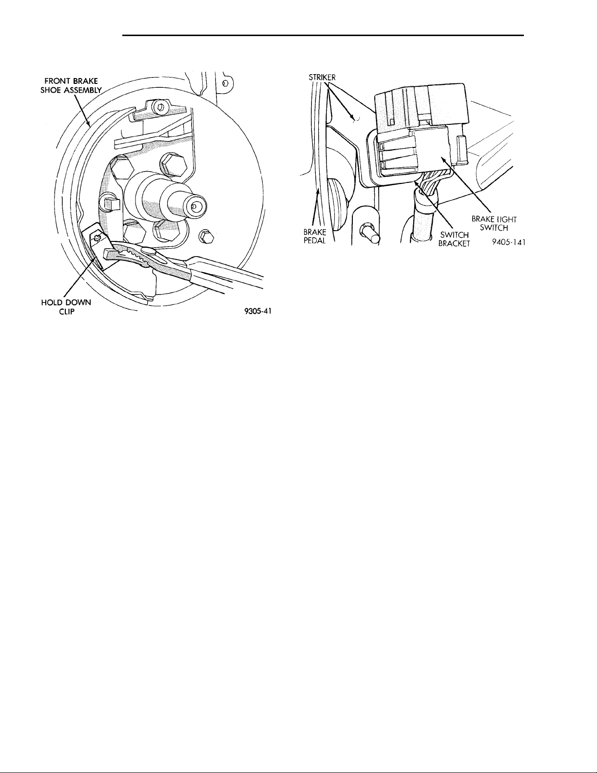
FRONT BRAKESHOE ASSEMBLYHOLD DOWN CLIP
BRAKELIGHTSWITCH SWITCH BRACKETBRAKE PEDALSTRIKER
5 - 56 BRAKES PL
REMOVAL AND INSTALLATION (Continued)
Fig. 163 Stop Lamp Switch
(1) Hold stop lamp switch firmly in one hand.
Then using other hand, pull outward on the plunger
of the stop lamp switch until it has ratcheted out to
its fully extended position.
Fig. 162 Front Hold Down Clip And Brake Shoe
(5) Install brake shoe adjuster assembly with star
wheel rearward (Fig. 159).
(6) Install rear brake shoe hold down clip (Fig.
158).
(7) Adjust brake shoes to a diameter to 171 mm
(6.75 inch).
(8) Install rear hub and bearing assembly on spin-
dle.
(9) Install A NEW hub and bearing assembly
retaining nut. Torque the hub and bearing assembly
retaining nut to 168 N·m (124 ft. lbs.).
(10) Install hub and bearing assembly dust cap.
(11) Install rear rotor.
(12) Install rear disc brake caliper on the adapter
(See Brake Shoe Removal).
(13) Install wheel and tire assemblies.
(14) Tighten wheel stud nuts to 129 N·m (95
ft.lbs.).
STOP LAMP SWITCH
REMOVE
(1) Depress and hold the brake pedal while rotat-
ing stop lamp switch (Fig. 163) in a counter-clockwise
direction approximately 30 degrees.
(2) Pull the switch rearward and remove from its
mounting bracket.
(3) Disconnect wiring harness connector from stop
lamp switch.
INSTALL
NOTE: Prior to installing stop lamp switch into
bracket, the plunger must be moved to its fully
extended position using procedure in Step 1.
(2) Connect the wiring harness connector to the
stop lamp switch.
(3) Mount the stop lamp switch into the bracket
using the following procedure. Depress the brake
pedal as far down as possible. Then install switch in
bracket by aligning index key on switch with slot at
top of square hole in mounting bracket. When switch
is fully installed in bracket, rotate switch clockwise
approximately 30° to lock switch into bracket.
CAUTION: Do not use excessive force when pulling
back on brake pedal to adjust the stop lamp switch.
If to much force is used, damage to the stop lamp
switch or striker (Fig. 163) can result.
(4) Gently pull back on brake pedal until the pedal
stops moving. This will cause the switch plunger to
ratchet backward to the correct position.
DISASSEMBLY AND ASSEMBLY
BRAKE FLUID RESERVOIR
NOTE: The master cylinder does not need to be
removed from the power brake vacuum booster for
replacement of the brake fluid reservoir.
(1) Clean master cylinder housing and brake fluid
reservoir.
(2) Remove the brake fluid reservoir cap. Using a
CLEAN syringe or equivalent type tool, empty as
much brake fluid as possible from the reservoir.
NOTE: Do not pry off using a tool, damage to reservoir may result.
Page 57

MASTER CYLIN-DER BRAKEFLUID RESER-VOIR MASTERCYL-INDERFLUID LEVEL SWITCH RETAININGTABS
MASTER CYLIN-DER BRAKEFLUID RESER-VOIR BRAKE FLUIDLEVEL SWITCHMASTERCYLINDER
POWER BRAKEBOOSTER MASTER CYLINDER BRAKEFLUID RESERVOIRBRAKE FLUIDLEVEL SENSORMASTER CYLINDER
PL BRAKES 5 - 57
DISASSEMBLY AND ASSEMBLY (Continued)
(3) Rock brake fluid reservoir from side to side
while pulling up to remove the reservoir from the
master cylinder housing (Fig. 164).
Fig. 165 Master Cylinder Fluid Level Sensor
Fig. 164 Removing Fluid Reservoir From Master
Cylinder
(4) Remove master cylinder housing to brake fluid
reservoir grommets.
(5) Install new master cylinder housing to brake
fluid reservoir sealing grommets (Fig. 164) in master
cylinder housing.
(6) Lubricate reservoir mounting area with fresh
clean brake fluid. Place reservoir in position over
grommets. Seat reservoir into grommets using a
rocking motion while firmly pressing down on fluid
reservoir.
(7) Be sure reservoir is positioned properly.
(8) Make sure bottom of reservoir touches top of
grommet.
BRAKE FLUID LEVEL SWITCH
The master cylinder or brake fluid reservoir does
not have to be removed from vehicle for replacement
of the brake fluid level sensor.
(1) Remove wiring harness connector from brake
fluid reservoir level sensor (Fig. 165).
(2) Compress retaining tabs (Fig. 166) on end of
brake fluid level switch.
(3) While compressing retaining tabs, grasp opposite end of brake fluid level switch and pull it out of
master cylinder brake fluid reservoir (Fig. 167).
(4) Correctly align the replacement level switch
with its mounting hole in the brake fluid reservoir.
Push switch into fluid reservoir until retaining tabs
are fully expanded on opposite side of fluid reservoir
(Fig. 166).
Fig. 166 Brake Fluid Level Switch Retaining Tabs
Fig. 167 Removing/Installing Fluid Reservoir Level
Switch
Page 58
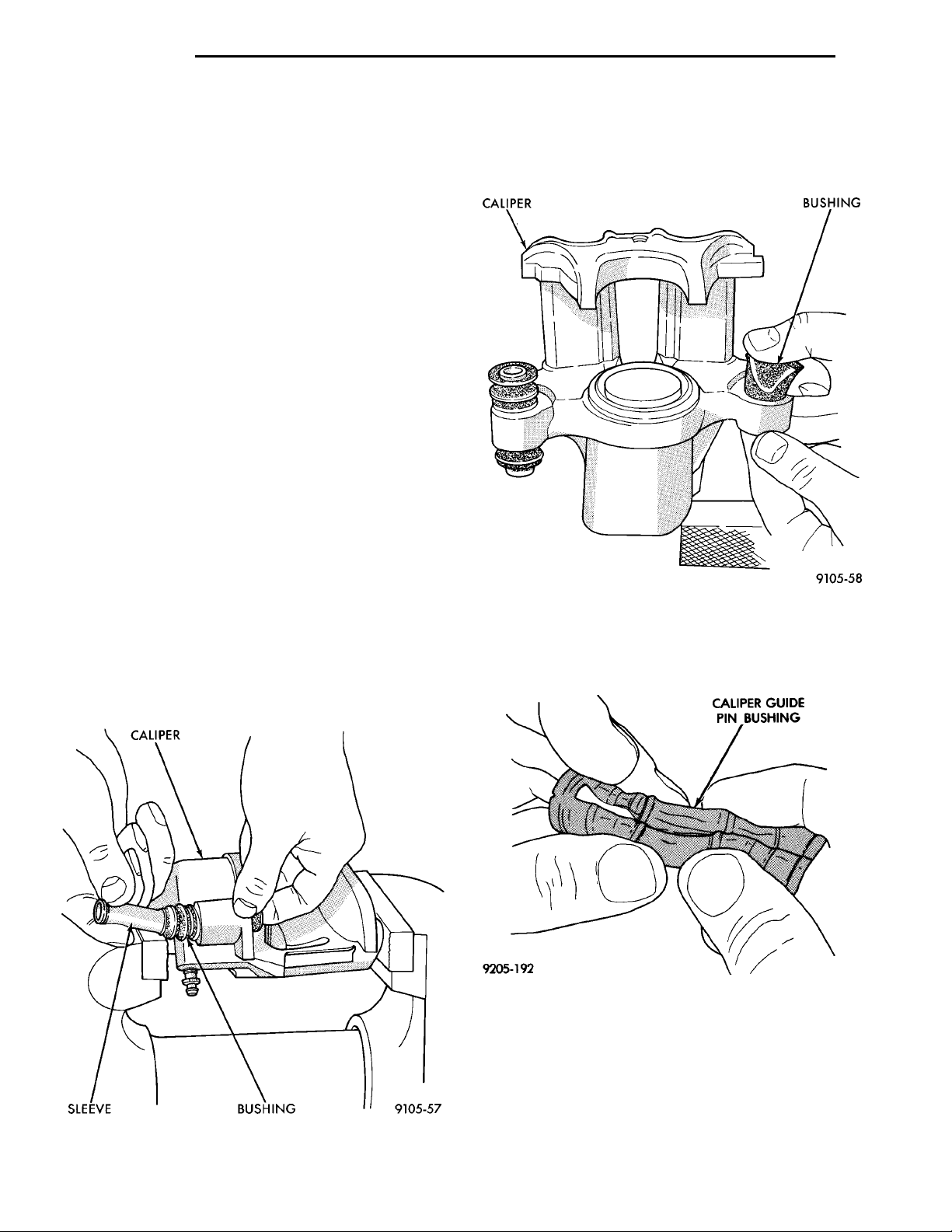
CALIPERSLEEVE BUSHING
CALIPER BUSHING
CALIPER GUIDE PINBUSHING
5 - 58 BRAKES PL
DISASSEMBLY AND ASSEMBLY (Continued)
(5) Install the wiring harness connector onto the
brake fluid level switch.
FRONT AND REAR DISC BRAKE CALIPER
CLEANING AND INSPECTION
Check for brake fluid leaks in and around dust
boot area and inboard brake pad, and for any ruptures, brittleness or damage to the piston dust boot.
If the dust boot is damaged, or a fluid leak is visible,
disassemble caliper assembly and install a new piston seal and dust boot, and piston if scored. Refer to
Caliper Disassembly And Re-Assembly Procedures in
Disc Brake Caliper Service in this section of the service manual.
Check the guide pin dust boots to determine if they
are in good condition. Replace if they are damaged,
dry, or found to be brittle. Refer to Guide Pin Bushing Service in Disc Brake Caliper Service in this section of the service manual.
CALIPER GUIDE PIN BUSHING SERVICE
The double pin caliper uses a sealed for life bushing and sleeve assembly. If required this assembly
can be serviced using the following procedure.
(3) Using your fingers, collapse one side of the
bushing. Then pull on the opposite side to remove
the bushing from the brake caliper housing (Fig.
169).
REMOVING CALIPER GUIDE PIN BUSHINGS
(1) Remove caliper from brake rotor (See Brake
Shoe Removal). Hang caliper assembly on a wire
hook away from the brake rotor.
(2) Push out and then pull the steel sleeve from
the inside of the bushing using your fingers as shown
in (Fig. 168).
Fig. 168 Removing Inner Sleeve From Bushing
Fig. 169 Removing Bushing From Caliper
INSTALLING CALIPER GUIDE PIN BUSHINGS
(1) Fold the bushing in half lengthwise at the solid
middle section of the bushing (Fig. 170).
Fig. 170 Folded Caliper Guide Pin Bushing
(2) Insert the folded bushing into the caliper hous-
ing (Fig. 171). Do not use a sharp object to per-
form this step due to possible damage to the
bushing.
(3) Unfold the bushing using your fingers or a
wooden dowel until the bushing is fully seated into
the caliper housing. Flanges should be seated evenly
on both sides of the bushing hole (Fig. 172).
Page 59
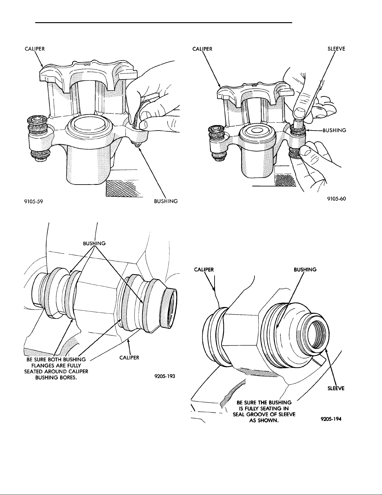
CALIPER BUSHING
BUSHING CALIPERBE SURE BOTH BUSHING FLANGES AREFULLY SEATEDAROUND CALIPER BUSH-ING BORES.
CALIPER SLEEVEBUSHING
CALIPER BUSHINGSLEEVEBE SURE THE BUSHING IS FULLYSEATING IN SEAL GROOVE OFSLEEVE AS SHOWN.
PL BRAKES 5 - 59
DISASSEMBLY AND ASSEMBLY (Continued)
Fig. 171 Installing Caliper Guide Pin Bushing
Fig. 172 Bushing Correctly Installed In Caliper
(4) Lubricate the inside surfaces of the bushing
using Mopar, Silicone Dielectric Compound or an
equivalent.
(5) Install guide pin sleeve into one end of bushing
until seal area of bushing is past seal groove in
sleeve (Fig. 173).
(6) Holding convoluted boot end of bushing with
one hand, push steel sleeve bushing through boot
Fig. 173 Installing Sleeve In Bushing
until one end of bushing is fully seated into seal
groove on one end of sleeve (Fig. 173).
(7) Holding sleeve in place, work other end of
bushing over end of sleeve and into the seal grove on
sleeve (Fig. 174). Be sure other end of bushing did
not come out of seal grove in sleeve.
Fig. 174 Correctly Installed Caliper Sleeve And
Bushing
(8) When the sleeve is seated properly into the
bushing, the sealed for life sleeve/bushing can be
Page 60
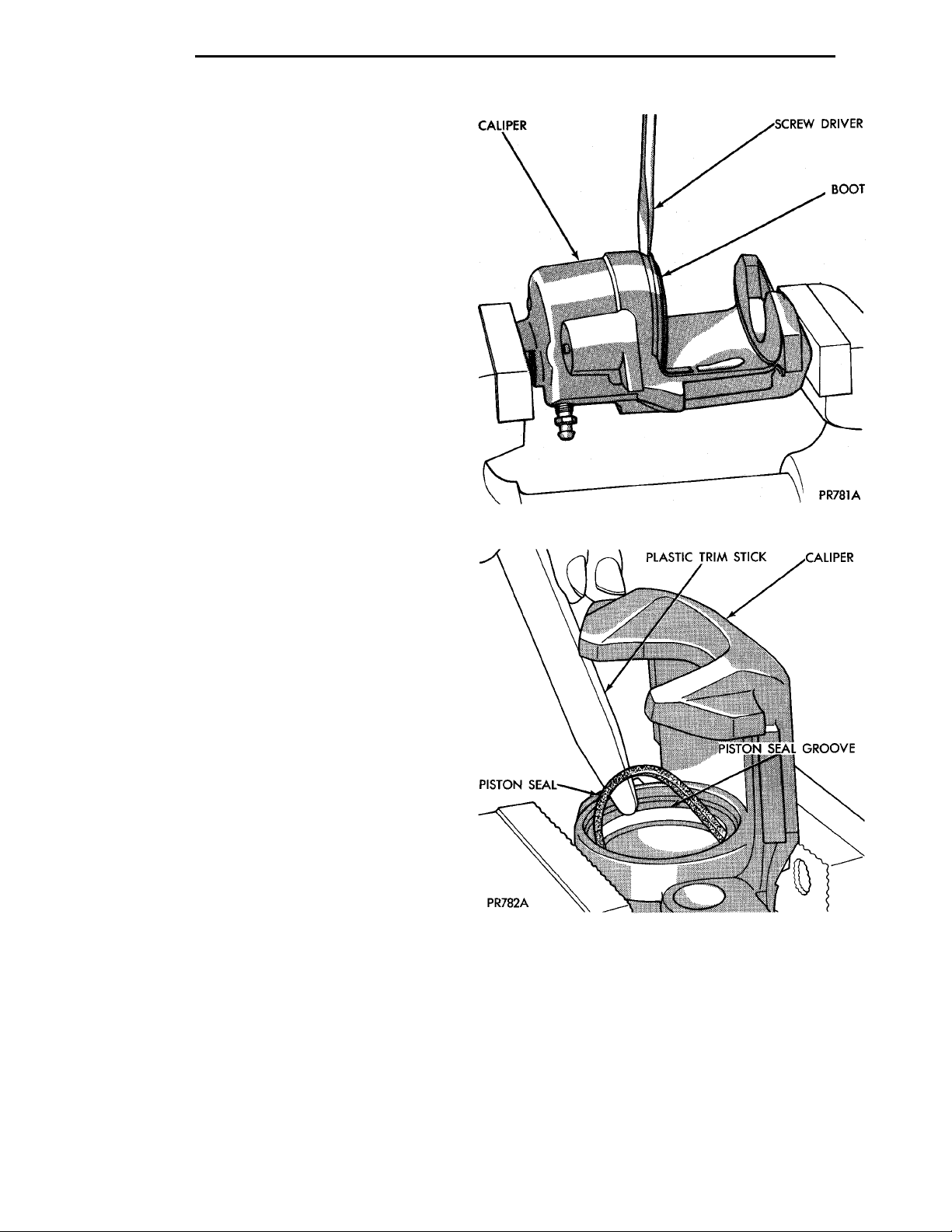
CALIPER SCREW DRIVERBOOT
PISTON SEAL
PLASTIC TRIM STICK CALIPER
PISTON SEAL GROOVE
5 - 60 BRAKES PL
DISASSEMBLY AND ASSEMBLY (Continued)
held between your fingers and easily slid back and
forth without the bushing unseating from the sleeve
groove.
CALIPER DISASSEMBLY
WARNING: UNDER NO CONDITION SHOULD AIR
PRESSURE EVER BE USED TO REMOVE A PISTON
FROM A CALIPER BORE. PERSONAL INJURY
COULD RESULT FROM SUCH A PRACTICE.
(1) Remove caliper from brake rotor (See Brake
Shoe Removal). Hang assembly on a wire hook away
from rotor, so hydraulic fluid cannot get on rotor.
Place a small piece of wood between the piston and
caliper fingers.
(2) Carefully depress brake pedal to hydraulically push piston out of bore. Then apply and hold
down the brake pedal to any position beyond the first
inch of pedal travel. This will prevent loss of brake
fluid from the master cylinder.
(3) If both front caliper pistons are to be removed,
disconnect brake tube at flexible brake hose at frame
rail. Plug brake tube and remove piston from opposite caliper using the same process as above for the
first piston removal.
(4) Disconnect the brake fluid flex hose from the
caliper assembly.
CAUTION: Do not use excessive force when clamping caliper in vise. Excessive vise pressure will
cause bore distortion and binding of piston.
(5) To disassemble caliper, mount in a vise
equipped with protective jaws.
(6) Remove guide pin sleeves and guide pin bushings. See Removing Guide Pin Bushings in the caliper disassembly section of this manual.
(7) Remove the piston dust boot from the caliper
and discard (Fig. 175).
(8) Using a soft tool, such as a plastic trim stick,
work piston seal out of its groove in caliper piston
bore (Fig. 176). Discard old seal. Do not use a
screw driver or other metal tool for this operation, because of the possibility of scratching
piston bore or burring edges of seal groove.
(9) Clean all parts using alcohol or a suitable solvent and wipe dry using only a lint free cloth. No
lint residue can remain in caliper bore. Clean out all
drilled passages and bores. Whenever a caliper
has been disassembled, a new boot and seal
must be installed at assembly.
(10) Inspect the piston bore for scoring or pitting.
Bores that show light scratches or corrosion can usually be cleared of the light scratches or corrosion
using crocus cloth. Bores that have deep scratches or
scoring should be honed. Use Caliper Hone, Special
Tool C-4095, or equivalent providing the diameter of
Fig. 175 Removing Caliper/Piston Dust Boot
Fig. 176 Removing Piston Seal From Caliper
the bore is not increased more than 0.0254 mm
(0.001 inch) (Fig. 177).
(11) If the bore does not clean up within this specification, a new caliper housing should be installed.
Install a new piston if the old one is pitted or scored.
NOTE: When using Caliper Honing Tool, Special
Tool C-4095, coat the stones and bore with brake
fluid. After honing the bore, carefully clean the seal
and boot grooves with a stiff non-metallic rotary
brush.
Page 61
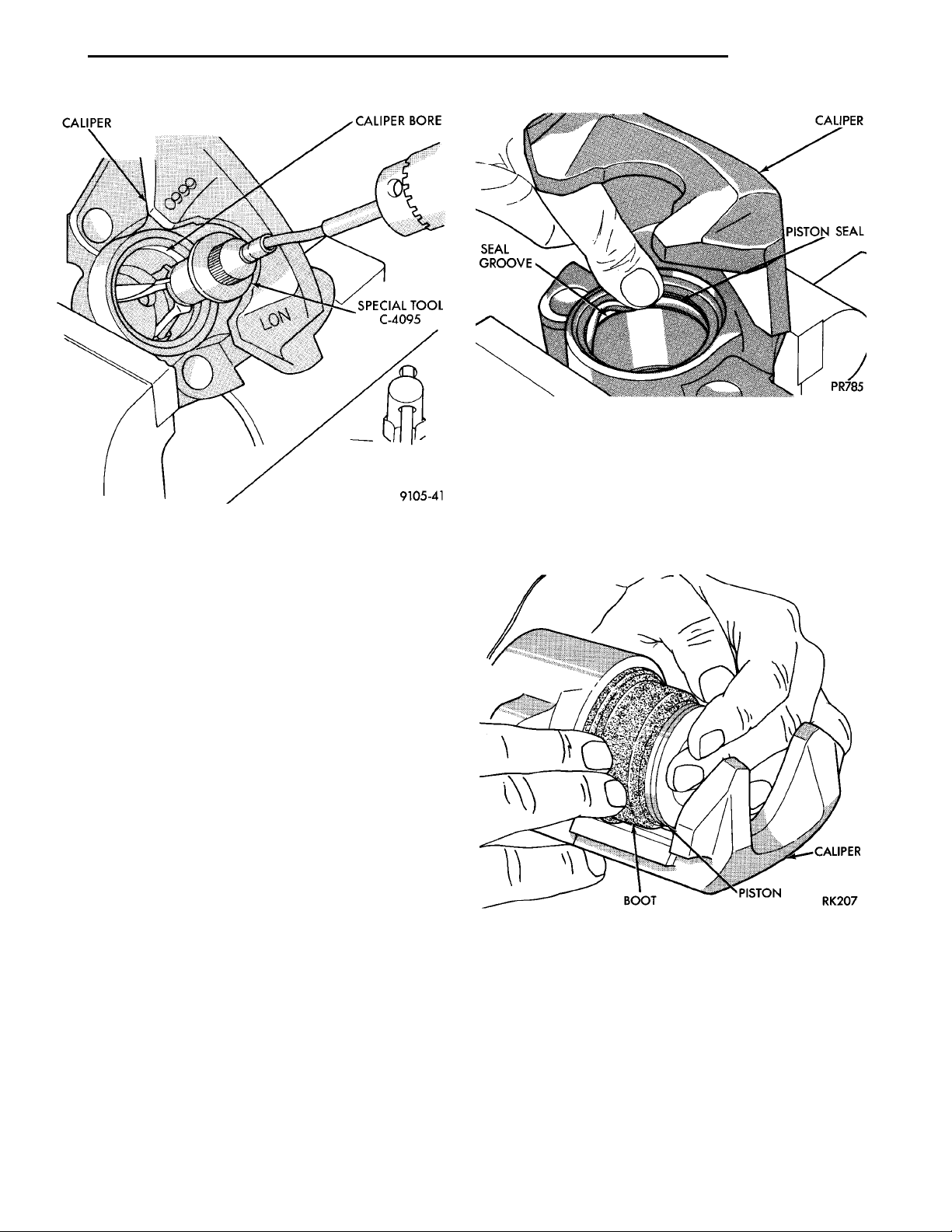
CALIPER CALIPERBORESPECIAL TOOLC-4095
PL BRAKES 5 - 61
DISASSEMBLY AND ASSEMBLY (Continued)
Fig. 178 Installing New Piston Seal In Caliper
CAUTION: Force must be applied to the piston uniformly to avoid cocking and binding of the piston in
the bore of the caliper.
Fig. 177 Honing Brake Caliper Piston Bore
NOTE: Use extreme care in cleaning the caliper
after honing. Remove all dirt and grit by flushing
the caliper with brake fluid; wipe dry with a clean,
lint free cloth and then clean a second time.
CAUTION: When inspecting caliper piston, do not
use anything but solvents to clean piston surface. If
surface of piston cannot be cleaned using only solvents, piston must be replaced.
(12) Inspect caliper piston for pitting, scratches, or
any physical damage. Replace piston if there is evidence of scratches, pitting or physical damage.
CALIPER ASSEMBLY
CAUTION: Excessive vise pressure will cause bore
distortion and binding of piston.
(1) Clamp caliper in a vise (with protective caps
installed on jaws of vise).
(2) Dip new piston seal in clean brake fluid and
install in the groove of the caliper bore. Seal should
be positioned at one area in groove and gently
worked around the groove (Fig. 178), using only your
fingers until properly seated. NEVER USE AN OLD
PISTON SEAL. Be sure that fingers are clean and
seal is not twisted or rolled (Fig. 178).
(3) Coat new piston boot with clean brake fluid
leaving a generous amount inside boot.
(4) Position dust boot over piston after coating
with brake fluid.
(5) Install piston into caliper bore pushing it past
the piston seal until it bottoms in the caliper bore
(Fig. 179).
Fig. 179 Installing Piston Into Caliper Bore
(6) Position dust boot into the counterbore of the
caliper assembly piston bore.
(7) Using a hammer and Installer Piston Caliper
Boot, Special Tool C-4689 and Handle, Special Tool
C-4171, drive boot into counterbore of the caliper
(Fig. 180).
(8) Install guide pin sleeves and bushings. See
Install Guide Pin Bushings section in the caliper disassembly section of this manual.
Page 62
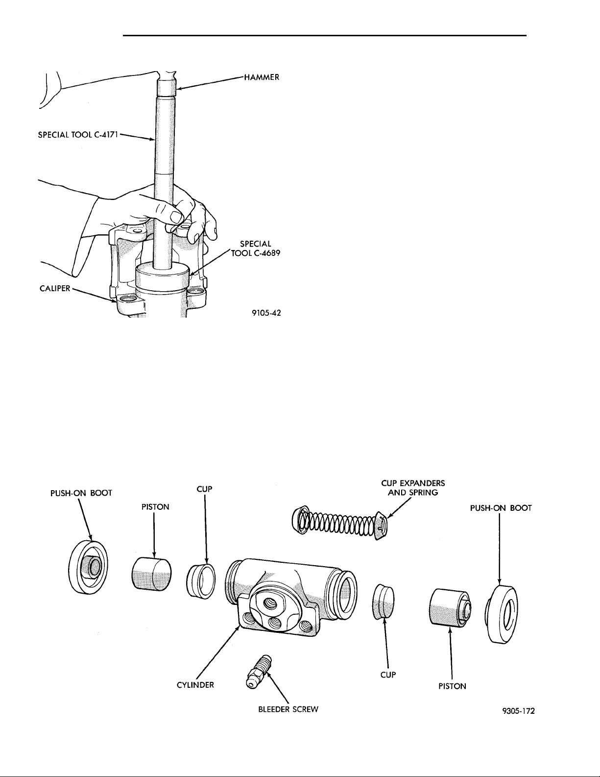
PUSH-ON BOOT PISTON CUP CUP EXPANDERS ANDSPRING PUSH-ON BOOTCYLINDER BLEEDER SCREW CUP PISTON
HAMMERSPECIAL TOOLC-4171 SPECIAL TOOLC-4689CALIPER
5 - 62 BRAKES PL
DISASSEMBLY AND ASSEMBLY (Continued)
(11) Install brake hose onto caliper using banjo
bolt. Torque the brake hose to caliper assembly banjo
bolt to 33 N·m (24 ft. lbs.). New seal washers
MUST always be used when installing brake
hose to caliper.
(12) Bleed the brake system (see Bleeding Brake
System).
WHEEL CYLINDER (REAR DRUM BRAKE)
DISASSEMBLE
To disassemble the wheel cylinders, proceed as follows:
(1) Pry boots away from cylinders and remove (Fig.
181).
(2) Press IN on one piston to force out opposite
piston, cup and spring (Fig. 181). Then using a soft
tool such as a dowel rod, press out the cup and piston
that remain in the wheel cylinder.
(3) Wash wheel cylinder, pistons, and spring (Fig.
181) in clean brake fluid or alcohol; (DO NOT USE
ANY PETROLEUM BASE SOLVENTS) clean thor-
Fig. 180 Installing Dust Boot In Caliper Counterbore
(9) Install brake pads. See Installing Brake Pads
in the Brake Pad Service Procedures section of this
manual.
(10) Before installing caliper assembly on vehicle,
inspect brake rotor. If any conditions as described in
Checking Brake Rotor for Runout and Thickness are
present the rotor, must be replaced or refaced. If the
rotor does not require any servicing, install caliper
assembly.
oughly and blow dry with compressed air. Inspect cylinder bore and piston for scoring and pitting. (Do not
use a rag as lint from the rag will stick to bore surfaces.)
(4) Wheel cylinder bores and pistons that are
badly scored or pitted should be replaced. Cylinder
walls that have light scratches, or show signs of corrosion, can usually be cleaned with crocus cloth,
using a circular motion. Black stains on the cylinder
walls are caused by piston cups and will not impair
operation of cylinder.
Fig. 181 Rear Wheel Cylinder (Exploded View)
Page 63

PL BRAKES 5 - 63
DISASSEMBLY AND ASSEMBLY (Continued)
ASSEMBLE
Before assembling the pistons and new cups in the
wheel cylinders, dip them in clean brake fluid. If the
boots are deteriorated, cracked or do not fit tightly on
the pistons or the cylinder casting, install new boots.
(1) Coat cylinder bore with clean brake fluid.
(2) Lightly coat the sealing lip and outer surfaces
of the wheel cylinder cups with Mopar Protect-A-Cup
Lubricant.
(3) Install expansion spring with cup expanders in
cylinder. Install cups in each end of cylinder with
open end of cups facing each other (Fig. 181).
(4) Install piston in each end of cylinder having
the flat face of each piston contacting the flat face of
each cup, already installed (Fig. 181).
(5) Coat the interior surfaces of the push on boots
(Fig. 181) with the Mopar Protect-A-Cup Lubricant
(6) Install a boot over each end of cylinder (Fig.
181). Be careful not to damage boot during
installation.
CLEANING AND INSPECTION
FRONT DISC BRAKES
BRAKE PAD LINING WEAR
If a visual inspection does not adequately determine the condition of the lining, a physical check will
be necessary. To check the amount of lining wear,
remove the wheel and tire assemblies, and the calipers.
Remove the front disc brake shoes. Refer to Front
Disc Brake Shoe Removal in the Removal And Installation section in this group of the service manual for
the required procedure.
The combined brake shoe and lining material
thickness should be measured at the thinnest part of
the assembly.
When a set of brake shoes are worn to a total
thickness of approximately 7.95 mm (5/16 inch) they
should be replaced.
Replace both brake shoe assemblies (inboard and
outboard). It is necessary that both front wheel sets
be replaced whenever brake shoe assemblies on
either side are replaced.
If the brake shoe assemblies do not require
replacement, reinstall, the assemblies making sure
each brake shoe is returned to the original position.
Refer to Front Disc Brake Shoe Installation in the
Removal And Installation section in this group of the
service manual for the required procedure.
CALIPER INSPECTION
Check for brake fluid leaks in and around boot
area and inboard lining, and for any ruptures, brittleness or damage to the piston dust boot. If the boot
is damaged, or a fluid leak is visible, disassemble caliper assembly and install a new seal and boot, and
piston if scored. Refer to Front Disc Brake Caliper in
the Disassembly And Assembly Section in this group
of the service manual.
Check the guide pin dust boots to determine if they
are in good condition. Replace if they are damaged,
dry, or found to be brittle. Refer to Front Disc Brake
Caliper in the Disassembly And Assembly Section in
this group of the service manual.
REAR DISC BRAKES
BRAKE PAD LINING WEAR
If a visual inspection does not adequately determine the condition of the lining, a physical check will
be necessary. To check the amount of lining wear,
remove the wheel and tire assemblies, and the calipers.
Remove the rear disc brake shoes. Refer to Rear
Disc Brake Shoe Removal in the Removal And Installation section in this group of the service manual for
the required procedure.
The combined brake shoe and lining material
thickness should be measured at the thinnest part of
the assembly.
When a set of brake shoes are worn to a total
thickness of approximately 7.0 mm (9/32 inch) they
should be replaced.
Replace both brake shoe assemblies (inboard and
outboard). It is necessary that both rear wheel sets
be replaced whenever brake shoe assemblies on
either side are replaced.
If the brake shoe assemblies do not require
replacement, reinstall, the assemblies making sure
each brake shoe is returned to the original position.
Refer to Rear Disc Brake Shoe Installation in the
Removal And Installation section in this group of the
service manual for the required procedure.
CALIPER INSPECTION
Check for brake fluid leaks in and around boot
area and inboard lining, and for any ruptures, brittleness or damage to the piston dust boot. If the boot
is damaged, or a fluid leak is visible, disassemble caliper assembly and install a new seal and boot, and
piston if scored. Refer to Rear Disc Brake Caliper in
the Disassembly And Assembly Section in this group
of the service manual.
Check the guide pin dust boots to determine if they
are in good condition. Replace if they are damaged,
dry, or found to be brittle. Refer to Rear Disc Brake
Caliper in the Disassembly And Assembly Section in
this group of the service manual.
Page 64
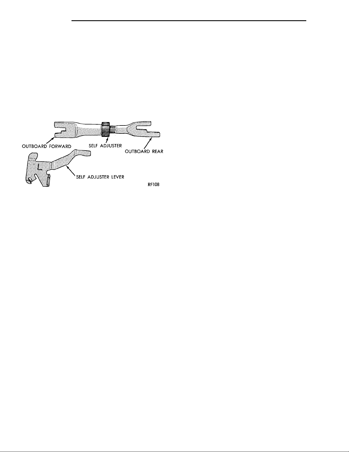
5 - 64 BRAKES PL
CLEANING AND INSPECTION (Continued)
REAR DRUM BRAKES
Rear brake shoe lining should show contact across
entire width of the lining and also from the heel to
the toe of the lining, otherwise replace.
Brake shoes with lack of contact at the toe or heel
of the brake shoe linng may be improperly ground.
OUTBOARDFORWARD SELF ADJUSTER OUTBOARDREARSELF ADJUSTER LEVER
Clean and inspect the brake support plate and
adjusting screws. Apply a thin coat of Mopar MultiPurpose Lubricant or equivalent to the threads of the
self adjuster (Fig. 182). Replace adjusting screw if
corroded.
Fig. 182 Adjuster Screw And Lever (Typical)
If old brake shoe return or hold down springs have
overheated or are damaged, replace. Overheating
indications are paint discoloration or distorted end
coils.
REAR DRUM BRAKE WHEEL CYLINDER
With brake drums removed, inspect the wheel cylinder boots for evidence of a brake fluid leak. Visually check the boots for cuts, tears, or heat cracks. If
any of these conditions exist, the wheel cylinders
should be completely cleaned, inspected and new
parts installed.
If a wheel cylinder is leaking and the brake lining
material is saturated with brake fluid, the brake
shoes must be replaced.
CHASSIS TUBES AND HOSES
Flexible rubber hose is used at both front and rear
brakes. Inspection of brake hoses should be performed whenever the brake system is serviced and
every 7,500 miles or 12 months, whichever comes
first (every engine oil change). Inspect hydraulic
brake hoses for severe surface cracking, scuffing,
worn spots or physical damage. If the fabric casing of
the rubber hose becomes exposed due to cracks or
abrasions in the rubber hose cover, the hose should
be replaced immediately. Eventual deterioration of
the hose can take place with possible burst failure.
Faulty installation can cause twisting, resulting in
wheel, tire, or chassis interference.
The steel brake tubing should be inspected periodically for evidence of corrosion, physical damage or
contact with moving or hot components of the vehicle.
REAR WHEEL HUB AND BEARING ASSEMBLY
The rear hub and bearing assembly is designed for
the life of the vehicle and should require no maintenance. The following procedure may be used for evaluation of bearing condition.
With wheel and brake drum removed, rotate
flanged outer ring of hub. Excessive roughness, lateral play or resistance to rotation may indicate dirt
intrusion or bearing failure. If the rear wheel bearings exhibit these conditions during inspection, the
hub and bearing assembly should be replaced.
Damaged bearing seals and resulting excessive
grease loss may also require bearing replacement.
Moderate grease loss from bearing is considered normal and should not require replacement of the hub
and bearing assembly.
ADJUSTMENTS
STOP LAMP SWITCH
(1) Remove stop lamp switch from its bracket by
rotating it approximately 30° in a counter-clockwise
direction.
(2) Disconnect wiring harness connector from stop
lamp switch.
(3) Hold stop lamp switch firmly in one hand.
Then using other hand, pull outward on the plunger
of the stop lamp switch until it has ratcheted out to
its fully extended position.
(4) Install the stop lamp switch into the bracket
using the following procedure. Depress the brake
pedal as far down as possible. Then while keeping
the brake pedal depressed, install the stop lamp
switch into the bracket by aligning index key on
switch with slot at top of square hole in mounting
bracket. When switch is fully installed in the square
hole of the bracket, rotate switch clockwise approximately 30° to lock the switch into the bracket.
CAUTION: Do not use excessive force when pulling
back on brake pedal to adjust the stop lamp switch.
If too much force is used, damage to the vacuum
booster, stop lamp switch or striker (Fig. 183) can
result.
(5) Connect the wiring harness connector to the
stop lamp switch.
(6) Gently pull back on brake pedal until the pedal
stops moving. This will cause the switch plunger
(Fig. 183) to ratchet backward to the correct position.
Page 65
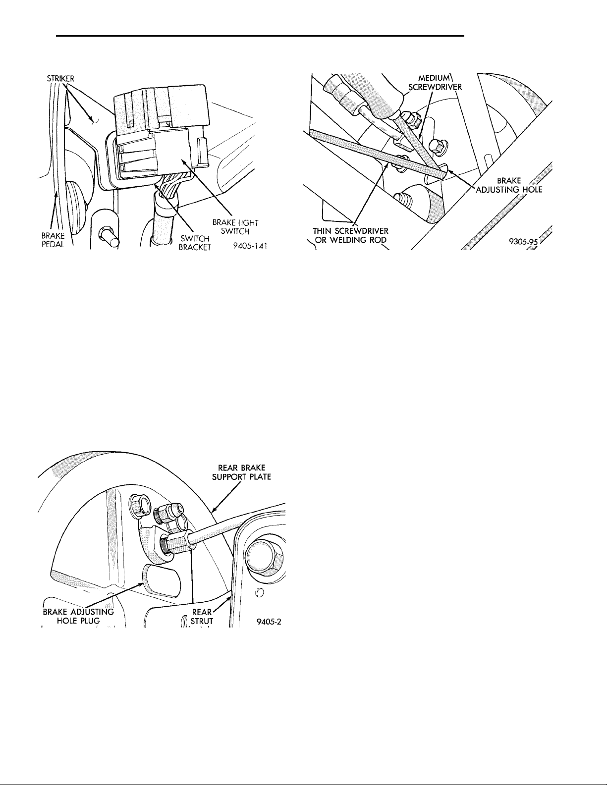
PL BRAKES 5 - 65
ADJUSTMENTS (Continued)
REAR BRAKE SUPPORTPLATEREAR STRUTBRAKE ADJUSTINGHOLE PLUG
Fig. 183 Stop Light Switch Location In Vehicle
REAR DRUM BRAKE SHOE ADJUSTMENT
NOTE: Normally, self adjusting drum brakes will
not require manual brake shoe adjustment.
Although in the event of a brake reline it is advisable to make the initial adjustment manually to
speed up the adjusting time.
(1) Raise the vehicle so all wheels are free to turn.
See Hoisting Recommendations in the Lubrication
And Maintenance Section at the front of this service
manual.
(2) Remove rear brake adjusting hole rubber plug
(Fig. 184) from the rear brake shoe support plate.
Fig. 185 Brake Drum Adjustment With Tool C-3784
(5) Insert a thin screwdriver or piece of welding
rod into brake adjusting hole (Fig. 185). Push adjusting lever out of engagement with star wheel. Care
should be taken so as not to bend adjusting
lever or distort lever spring. While holding
adjusting lever out of engagement with star wheel,
back off star wheel to ensure a free wheel with no
brake shoe drag.
(6) Repeat above adjustment at the other rear
wheel. Install adjusting hole rubber plugs (Fig. 184)
in rear brake supports.
(7) Apply and release the park brake lever one
time after wheel brake adjustment.
PARKING BRAKE ADJUSTMENT
VEHICLE EQUIPPED REAR DRUM BRAKES
Due to the auto adjust feature of the parking brake
lever, adjustment of the parking brake system on
vehicles equipped with rear drum brakes relies on
proper drum brake shoe adjustment. See Rear Brake
Adjustment in the Service Adjustments Section in
this group of the service manual.
Fig. 184 Rear Brake Adjusting Hole Plug
(3) Be sure parking brake lever is fully
released.
(4) Insert Brake Adjuster, Special Tool C-3784,
(Fig. 185) or equivalent, through the adjusting hole
in support plate and against star wheel of adjusting
screw. Move handle of tool downward until a slight
drag is felt when the road wheel is rotated.
VEHICLE EQUIPPED REAR DISC BRAKES
Due to the auto adjust feature of the parking brake
lever, adjustment of the parking brake system on
vehicles equipped with rear disc brakes relies on
proper drum-in-hat brake shoe adjustment. See Rear
Park Brake Adjustment in the Parking Brakes Section in this group of the service manual.
SPECIFICATIONS
BRAKE FLUID
The brake fluid used in this vehicle must conform
to DOT 3 specifications and SAE J1703 standards.
No other type of brake fluid is recommended or
approved for usage in the vehicle brake system. Use
Page 66

5 - 66 BRAKES PL
SPECIFICATIONS (Continued)
only Mopar brake fluid or an equivalent from a
tightly sealed container.
CAUTION: Never use reclaimed brake fluid or fluid
from an container which has been left open. An
open container will absorb moisture from the air
and contaminate the fluid.
CAUTION: Never use any type of a petroleumbased fluid in the brake hydraulic system. Use of
such type fluids will result in seal damage of the
vehicle brake hydraulic system causing a failure of
the vehicle brake system. Petroleum based fluids
would be items such as engine oil, transmission
fluid, power steering fluid ect.
BRAKE ACTUATION SYSTEM
ACTUATION:
Vacuum Operated Power Brakes ........Standard
Hydraulic System ..........Dual-Diagonally Split
MASTER CYLINDER ASSEMBLY:
Type ..........................Dual Tandem
Body Material ..............Anodized Aluminum
Reservoir Material ...............Polypropelene
MASTER CYLINDER BORE / STROKE AND
SPLIT:
NonABS ...................21mmx32.6 mm
(.875 in. x 1.28 in.)
ABS .......................21mmx32.7 mm
(.874 in. x 1.29 in.)
Displacement Split ....................50/50
MASTER CYLINDER FLUID OUTLET PORTS:
ABS..........Primary 3/8–24 Secondary 7/16–24
NonABS.................Primary Inboard And
Outboard 7/16–24
NonABS...................Secondary Inboard
And Outboard 3/8–23
Outlet Fitting Type ......SAE45°Inverted Flare
ABS HYDRAULIC CONTROL UNIT:
Hydraulic Tube Fitting
Type................SAE45°Inverted Flare
BOOSTER:
Make/Type ....................Bendix Vacuum
W/&W/O ABS
Mounting Studs ....................M8x1.25
Type .........................230mmSingle
Boost At 20 inches Of
Manifold Vacuum ..................4690 All
SCREW IN PROPORTIONING VALVE:
Material ..........................Aluminum
Function .......Hydraulic Pressure Proportioning
BRAKE PEDAL
Pedal Ratio ............................3.28
BRAKE FASTENER TORQUE SPECIFICATIONS
DESCRIPTION TORQUE
BRAKE TUBES:
Tube Nuts To Fittings And
Components Except HCU. ............17N·m
(145 in. lbs.)
From Master Cylinder To
HCU At HCU Ports .................21N·m
(185 in. lbs.)
BRAKE HOSE:
To Caliper Banjo Bolt .........48N·m(35ft.lbs.)
Intermediate Bracket ........12N·m(105 in. lbs.)
MASTER CYLINDER:
To Vacuum Booster
Mounting Nut ...........28N·m(250 in. lbs.)
BRAKE BOOSTER:
To Dash Panel
Mounting Nuts ...........28N·m(250 in. lbs.)
REAR WHEEL CYLINDER:
To Support Plate
Mounting Bolts ...........13N·m(115in.lbs.)
Bleeder Screw ..............10N·m(80in.lbs.)
BRAKE SUPPORT PLATE:
To Axle Mounting Bolts .......75N·m(55ft.lbs.)
REAR DISC BRAKE ADAPTER:
To Axle Mounting Bolts .......75N·m(55ft.lbs.)
DISC BRAKE CALIPER:
Guide Pin Bolts ............22N·m(192 in. lbs.)
Bleeder Screw .............15N·m(125 in. lbs.)
ABS HYDRAULIC CONTROL UNIT:
To Mounting Bracket Bolts . . . 28 N·m (250 in. lbs.)
Bracket To Frame Rail
Mounting Bolt (Top) .......18N·m(160 in. lbs.)
Bracket To Frame Rail
Mounting Bolts (Side) .....22N·m(200 in. lbs.)
PARKING BRAKE:
Lever Mounting Nuts ........28N·m(250 in. lbs.)
REAR HUB AND BEARING:
To Knuckle Retaining Nut . . . 217 N·m (160 ft. lbs.)
WHEEL:
Stud Lug Nut .......109–150 N·m (80–110 ft. lbs.)
Page 67
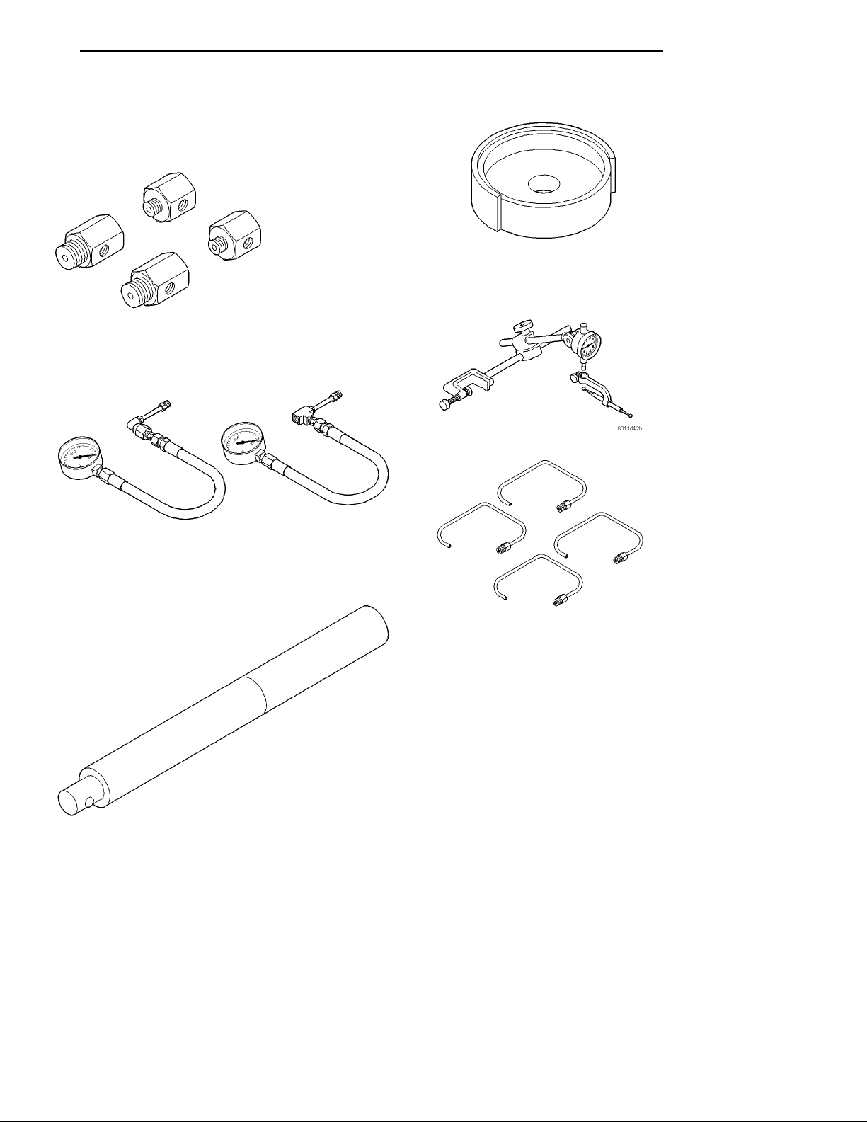
PL BRAKES 5 - 67
SPECIAL TOOLS
BASE BRAKE SYSTEM
Installer, Dust Boot C-4689
Adapters, Brake Pressure Test 6805
Dial Indicator C-3339
Gauge Set C-4007-A
Handle, Universal C-4171
Tubes, Master Cylinder Bleeding 6802
Page 68

5 - 68 BRAKES PL
ANTILOCK BRAKE SYSTEM–BENDIX ABX-4
INDEX
page page
DESCRIPTION AND OPERATION
ABS BRAKING MODE HYDRAULIC CIRCUIT
SOLENOID AND VALVE FUNCTION ....... 73
ABS COMPONENT ABBREVIATION LIST ..... 68
ABS COMPONENTS .................... 69
ABS HYDRAULIC CONTROL UNIT (HCU) .... 70
ABS OPERATION AND VEHICLE
PERFORMANCE ...................... 69
ABS WARNING LAMP FUNCTION AND
LOCATION .......................... 73
ANTILOCK BRAKES OPERATION
DESCRIPTION ....................... 68
CONTROLLER ANTILOCK BRAKE (CAB) ..... 72
HYDRAULIC CONTROL UNIT DECAY
SOLENOIDS ......................... 70
HYDRAULIC CONTROL UNIT FLUID SUMPS . . 70
HYDRAULIC CONTROL UNIT PUMP MOTOR
ASSEMBLY .......................... 71
HYDRAULIC CONTROL UNIT SHUTTLE
VALVES ............................ 70
MASTER CYLINDER AND POWER BRAKE
BOOSTER ........................... 70
PROPORTIONING VALVES ............... 71
PUMP/MOTOR RELAY OPERATION ......... 71
RELAY BOX ........................... 71
SYSTEM RELAY OPERATION ............. 71
WHEEL SPEED SENSORS ............... 72
DIAGNOSIS AND TESTING
ABS GENERAL DIAGNOSTICS
INFORMATION ....................... 74
ABS SERVICE PRECAUTIONS ............ 76
BRAKE FLUID CONTAMINATION ........... 76
DIAGNOSTIC TESTER (DRB) .............. 74
DIAGNOSTIC TROUBLE CODE
INFORMATION ....................... 74
DIAGNOSTICS MANUAL INFORMATION ..... 74
DRB DIAGNOSTIC CONNECTOR .......... 74
INTERMITTENT DIAGNOSTIC TROUBLE
CODES ............................. 75
PROPORTIONING VALVES ............... 75
SELF DIAGNOSTICS INFORMATION ........ 74
TONEWHEEL INSPECTION ............... 75
VEHICLE TEST DRIVE INFORMATION AND
PROCEDURE ........................ 76
SERVICE PROCEDURES
BLEEDING PROCEDURE INFORMATION .... 76
BRAKE FLUID LEVEL INSPECTION ......... 76
REMOVAL AND INSTALLATION
ABS HYDRAULIC CONTROL UNIT .......... 78
CONTROLLER ANTILOCK BRAKES (CAB) .... 83
FRONT WHEEL SPEED SENSOR .......... 83
GENERAL SERVICE CAUTIONS ........... 77
MASTER CYLINDER AND POWER BRAKE
BOOSTER ........................... 81
PROPORTIONING VALVES ............... 81
REAR WHEEL SPEED SENSOR ........... 84
RELAY BOX ........................... 81
SPECIFICATIONS
BRAKE FASTENER TORQUE
SPECIFICATIONS ..................... 85
SPEED SENSOR TONE WHEEL RUNOUT .... 85
WHEEL SPEED SENSOR TO TONE WHEEL
CLEARANCE ......................... 85
DESCRIPTION AND OPERATION
ANTILOCK BRAKES OPERATION DESCRIPTION
The purpose of the Antilock Brake System (ABS) is
to prevent wheel lock-up under heavy braking conditions on virtually any type of road surface. Antilock
Braking is desirable because a vehicle which is
stopped without locking the wheels will retain directional stability and some steering capability. This
allows the driver to retain greater control of the vehicle during heavy braking.
This section of the service manual covers the
description and on car service for the Bendix ABX-4
Brake System. If other service is required on the non
ABS related components of the brake system, refer to
the appropriate section in this group of the manual
for the specific service procedure required.
ABS COMPONENT ABBREVIATION LIST
In this section of the service manual several abbreviations are used for the components that are in the
Bendix ABX-4 Brake System. These components are
listed below for your reference.
• CAB—Controller Antilock Brake
• HCU—Hydraulic Control Unit
• ABS—Antilock Brake System
• PSI—Pounds per Square Inch (pressure)
• WSS—Wheel Speed Sensor
• FWD—Front Wheel Drive
• DTC—Diagnostic Trouble Code
Page 69

PL BRAKES 5 - 69
DESCRIPTION AND OPERATION (Continued)
ABS OPERATION AND VEHICLE PERFORMANCE
This ABS System represents the current state-ofthe-art in vehicle braking systems and offers the
driver increased safety and control during braking.
This is accomplished by a sophisticated system of
electrical and hydraulic components. As a result,
there are a few performance characteristics that may
at first seem different but should be considered normal. These characteristics are discussed below.
NORMAL BRAKING SYSTEM FUNCTION
Under normal braking conditions, the ABS System
functions the same as a standard brake system with
a diagonally split master cylinder and conventional
vacuum assist.
ABS SYSTEM OPERATION
If a wheel locking tendency is detected during a
brake application, the brake system will enter the
ABS mode. During ABS braking, hydraulic pressure
in the four wheel circuits is modulated to prevent
any wheel from locking. Each wheel circuit is
designed with a set of electric solenoids to allow modulation, although for vehicle stability, both rear
wheel solenoids receive the same electrical signal.
During an ABS stop, the brakes hydraulic system
is still a diagonally split. However, the brake system
pressure is further split into three control channels.
During antilock operation of the vehicle brake system, the front wheels are controlled independently
and are on two separate control channels. The rear
wheels of the vehicle however, are controlled together
through one control channel.
The system can build and release pressure at each
wheel, depending on signals generated by the wheel
speed sensors (WSS) at each wheel and received at
the Controller Antilock Brake (CAB).
ABS operation is available at all vehicle speeds
above 3 to 5 mph. Wheel lockup may be perceived at
the very end of an ABS stop and is considered normal.
VEHICLE HANDLING PERFORMANCE DURING ABS BRAKING
It is important to remember that an antilock brake
system does not shorten a vehicle’s stopping distance
under all driving conditions, but does provide
improved control of the vehicle while stopping. Vehicle stopping distance is still dependent on vehicle
speed, weight, tires, road surfaces and other factors.
Though ABS provides the driver with some steering control during hard braking, there are conditions
however, where the system does not provide any benefit. In particular, hydroplaning is still possible when
the tires ride on a film of water. This results in the
vehicles tires leaving the road surface rendering the
vehicle virtually uncontrollable. In addition, extreme
steering maneuvers at high speed or high speed cornering beyond the limits of tire adhesion to the road
surface may cause vehicle skidding, independent of
vehicle braking. For this reason, the ABS system is
termed Antilock instead of Anti-Skid.
NOISE AND BRAKE PEDAL FEEL
During ABS braking, some brake pedal movement
may be felt. In addition, ABS braking will create
ticking, popping and/or groaning noises heard by the
driver. This is normal due to pressurized fluid being
transferred between the master cylinder and the
brakes. If ABS operation occurs during hard braking,
some pulsation may be felt in the vehicle body due to
fore and aft movement of the suspension as brake
pressures are modulated.
At the end of an ABS stop, ABS will be turned off
when the vehicle is slowed to a speed of 3–4 mph.
There may be a slight brake pedal drop anytime that
the ABS is deactivated, such as at the end of the stop
when the vehicle speed is less then 3 mph or during
an ABS stop where ABS is no longer required. These
conditions will exist when a vehicle is being stopped
on a road surface with patches of ice, loose gravel or
sand on it. Also stopping a vehicle on a bumpy road
surface may activate the ABS because of the wheel
hop caused by the bumps.
TIRE NOISE AND MARKS
Although the ABS system prevents complete wheel
lock-up, some wheel slip is desired in order to
achieve optimum braking performance. Wheel slip is
defined as follows, 0 percent slip means the wheel is
rolling freely and 100 percent slip means the wheel is
fully locked. During brake pressure modulation,
wheel slip is allowed to reach up to 25 to30%. This
means that the wheel rolling velocity is 25 to 30%
less than that of a free rolling wheel at a given vehicle speed. This slip may result in some tire chirping,
depending on the road surface. This sound should not
be interpreted as total wheel lock-up.
Complete wheel lock up normally leaves black tire
marks on dry pavement. The ABS System will not
leave dark black tire marks since the wheel never
reaches a fully locked condition. Tire marks may
however be noticeable as light patched marks.
ABS COMPONENTS
The following is a detailed description of the Allied
Signal ABX-4 ABS brake system components. For
information on servicing the base brake system components, see the Base Brake section of this Service
Manual.
Page 70
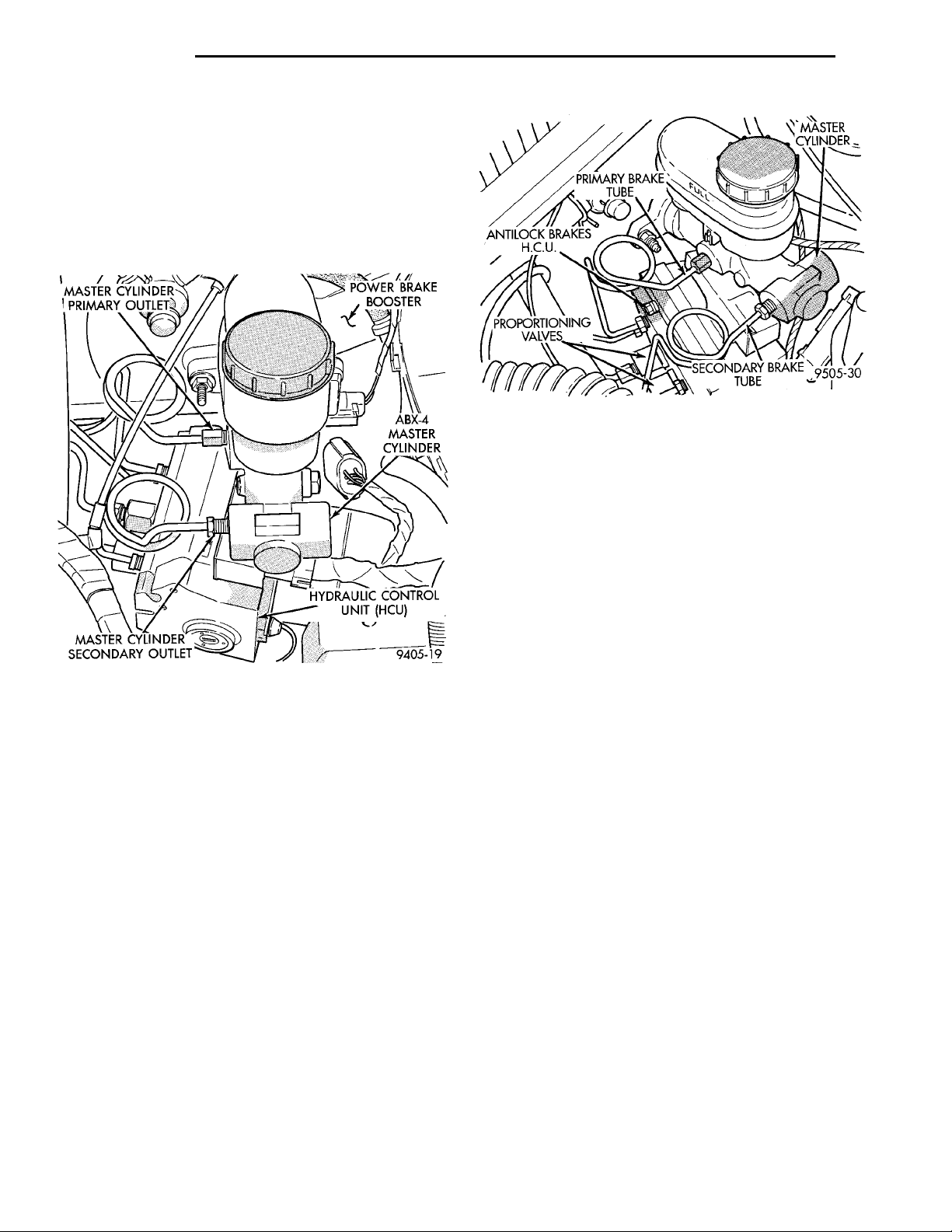
PRIMARYBRAKETUBEMASTER CYLINDERSECONDARYBRAKE TUBEPROPOR-TIONINGVALVESANTILOCK BRAKESH.C.U.
5 - 70 BRAKES PL
MASTER CYLINDERPRIMARY OUTLETMASTER CYLINDER SEC-ONDARY OUTLET POWER BRAKEBOOSTERABX-4 MASTER CYL-INDERHYDRAULIC CONTROLUNIT (HCU)
DESCRIPTION AND OPERATION (Continued)
MASTER CYLINDER AND POWER BRAKE BOOSTER
The Bendix ABX-4 ABS System uses a modified
master cylinder and power brake booster assembly
(Fig. 1). The master cylinder primary and secondary
outputs go directly to the hydraulic control unit
(HCU). Refer to the appropriate base brake section in
this group of the service manual for further information on the individual components.
Fig. 2 Hydraulic Control Unit Location In Vehicle
HYDRAULIC CONTROL UNIT DECAY SOLENOIDS
There are 4 decay solenoids, one for each wheel. In
the released position they provide a fluid path from
the master cylinder to the wheel brakes of the vehicle. In the actuated (decay) position, they provide a
fluid path from wheel brakes of the vehicle to the
sumps. The Decay solenoids are spring loaded in the
released (build) position during normal braking.
Fig. 1 ABX-4 Master Cylinder And Brake Booster
Assembly
ABS HYDRAULIC CONTROL UNIT (HCU)
WARNING: THE ONLY PARTS OF THE HYDRAULIC
CONTROL UNIT (HCU) THAT ARE SERVICEABLE,
ARE THE RELAY BOX, THE PROPORTIONING
VALVES, AND THE HCU MOUNTING BRACKET. THE
REMAINING COMPONENTS OF THE HYDRAULIC
CONTROL UNIT (HCU) ARE NOT SERVICEABLE
ITEMS. NO ATTEMPT SHOULD EVER BE MADE TO
REMOVE OR SERVICE ANY OTHER PARTS OF THE
HYDRAULIC CONTROL UNIT (HCU).
The hydraulic control unit (HCU) is located under
the master cylinder and power brake booster and is
mounted to the left frame rail (Fig. 2). The HCU contains the following components for controlling the
vehicle’s braking system during ABS braking: 4
Decay Valves, 4 Shuttle Valves, 2 Fluid Sumps, a
Pump/Motor and a relay box. Also attached to the
hydraulic control unit are the rear brake proportioning valves and the vehicles 6 hydraulic brake tubes
(Fig. 2).
HYDRAULIC CONTROL UNIT SHUTTLE VALVES
There are 4 Shuttle Valves, one for each wheel.
The Shuttle Valve is a hydraulically actuated valve
which shuttles when the decay solenoid and pump
are energized. This places an orifice (restriction) in
the line between the pump and the decay solenoid.
This restriction provides a controlled build rate to
each wheel brake during an ABS stop. The Shuttle
Valve will remain in the orificed position until the
ABS cycle is complete. When the ABS cycle has been
completed the decay solenoids will return to their
released position which will equalize the pressure
across the Shuttle Valves. When the pressure equalizes, the spring loaded Shuttle Orifice valves will
return to the unrestricted position.
HYDRAULIC CONTROL UNIT FLUID SUMPS
There are two fluid sumps in the hydraulic control
unit (HCU), one each for the primary and secondary
hydraulic circuits. The fluid sumps temporarily store
brake fluid that is decayed from the wheel brakes
during an ABS cycle. This fluid is then delivered to
the pump to provide build pressure. The typical pressure in the sumps is 50 psi, during ABS operation
only.
Page 71
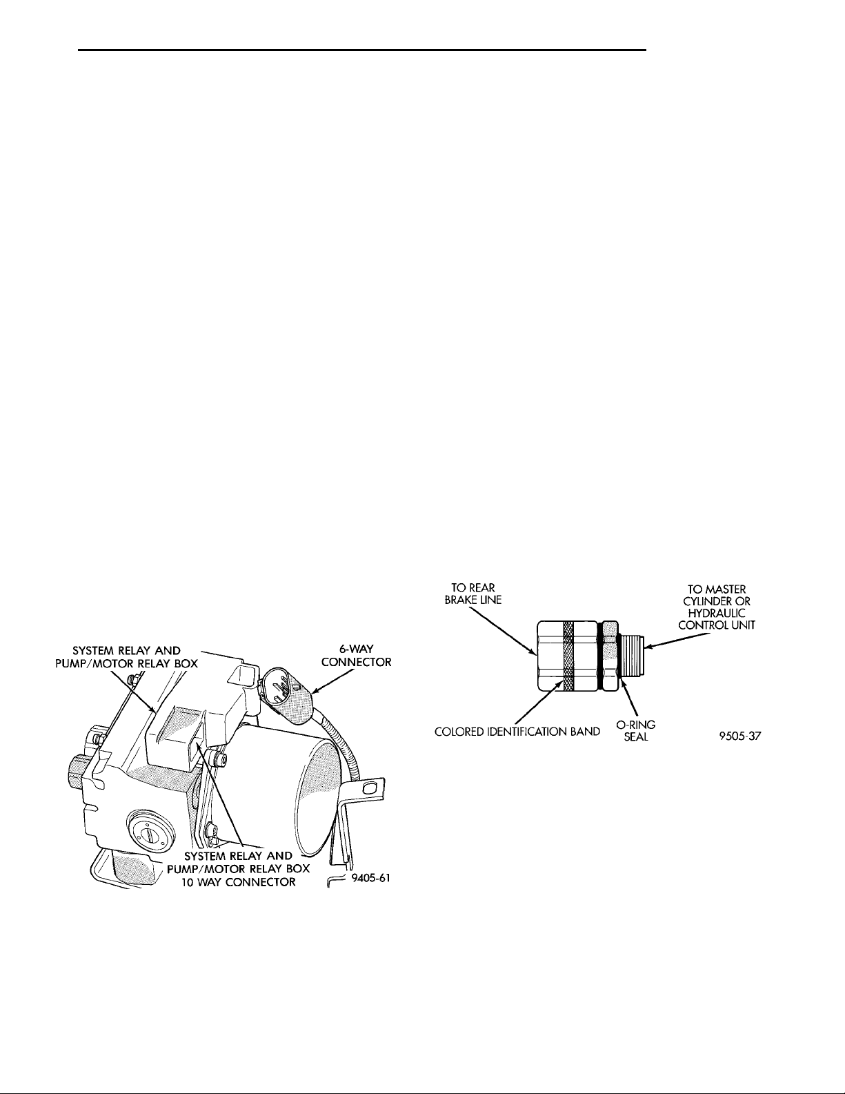
SYSTEM RELAY AND PUMP/MOTOR RELAY BOX 6-WAY CON-NECTORSYSTEM RELAY AND PUMP/MO-TOR RELAY BOX 10 WAY CON-NECTOR
TO REAR BRAKE LINE TO MASTER CYLINDER ORHYDRAULIC CONTROL UNITO-RING SEALCOLORED IDENTIFI-CATION BAND
PL BRAKES 5 - 71
DESCRIPTION AND OPERATION (Continued)
HYDRAULIC CONTROL UNIT PUMP MOTOR
ASSEMBLY
The HCU contains 2 Pump Assemblies, one each
for the primary and secondary hydraulic circuits.
Both pumps are driven by a common electric motor
which is part of the HCU. The pumps pick up fluid
from the sumps to supply build pressure to the
brakes during an ABS stop. The motor only runs during an ABS stop and is controlled by the CAB via the
Pump/Motor Relay. The Pump/Motor Assembly is not
a serviceable item. If it requires service the HCU
must be replaced.
RELAY BOX
ABX-4 utilizes two relays contained in a relay box
mounted to the HCU. The relay box contains a system relay and a pump/motor relay. A single 10-way
connector provides the electrical interface. The relay
box is serviceable as an assembly.
PUMP/MOTOR RELAY OPERATION
Pump/Motor power is supplied by the Pump/Motor
Relay. The pump motor relay is also part of the relay
box (Fig. 3) mounted to the HCU. If pump/motor
relay replacement is required, it is also only serviced
by the replacement of the relay box assembly (Fig. 3).
Voltage for the 12 volt side of the relay coil is provided by the system relay. The ground path through
the relay coil is completed by the CAB during ABS
braking. The relay contacts are closed when the relay
is energized. This provides 12 volts to the pump/motor as needed during ABS braking.
SYSTEM RELAY OPERATION
The main purpose of the system relay is to put the
ABS system into a stand-by mode for ABS operation.
The system relay is energized by the CAB shortly
after the ignition switch is turned on.
When energized by the CAB, the system relay
turns off the ABS warning lamp and provides 12
volts to the CAB. This voltage can then be used by
the CAB to energize the decay solenoids during ABS
braking. When energized, the system relay also provides the pump/motor relay coil with 12 volts. The
ground path to the pump/motor relay is completed by
the CAB during ABS braking.
Conversely, when the system relay is de-energized,
the ABS warning lamp is illuminated, voltage to the
decay solenoids is cut off, and the pump/motor relay
is prevented from energizing. Typically, the system
relay is de-energized by the controller when a fault is
detected that requires turning ABS off.
PROPORTIONING VALVES
Two Proportioning Valves are used in the system,
one for each rear brake hydraulic circuit. The Proportioning Valves function the same as in a standard
brake system. The Proportioning Valves are located
on the side of the HCU. The proportioning valve
application is identified by the colored band on the
proportioning valve (Fig. 4).
Fig. 3 System Relay And Pump/Motor Relay Box
Fig. 4 Proportioning Valve Identification
Page 72
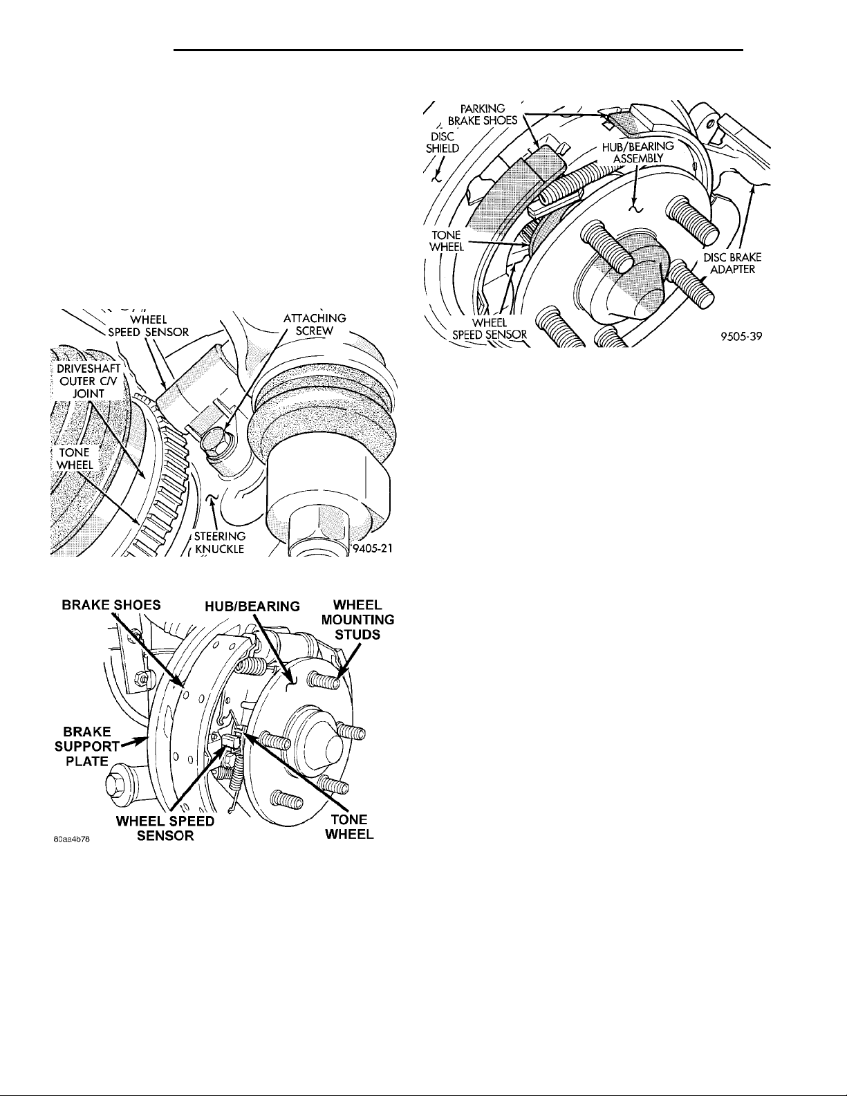
5 - 72 BRAKES PL
DESCRIPTION AND OPERATION (Continued)
WHEEL SPEED SENSORS
One Wheel Speed Sensor (WSS) is located at each
wheel (Fig. 5), (Fig. 6) and (Fig. 7), and sends a small
AC signal to the control module (CAB). This signal is
generated by magnetic induction created when a
toothed sensor ring (tone wheel) (Fig. 5) passes the
stationary magnetic Wheel Speed Sensor. The (CAB)
DRIVESHAFTOUTER C/V JOINT
TONEWHEEL STEERINGKNUCKLE ATTACHING SCREW
converts the AC signal generated at each wheel into
a digital signal. If a wheel locking tendency is
detected by the CAB, it will then modulate hydraulic
pressure via the HCU to prevent the wheel(s) from
locking.
WHEEL SPEED SENSOR
BRAKE SHOESHUB/BEARINGWHEEL MOUNTING STUDSTONE WHEELWHEEL SPEED SENSORBRAKE SUPPORT PLATE
Fig. 5 Front Wheel Speed Sensor
Fig. 7 Wheel Speed Sensor With Disc Brakes
7) and the rear tone wheel is also an integral part of
the rear wheel hub and bearing assembly. The speed
sensor air gap on both applications is NOT adjustable.
The four Wheel Speed Sensors are serviced individually. The front Tone Wheels are serviced as an
assembly with the outboard constant velocity joint.
The rear Tone Wheels are serviced as an assembly
with the rear hub and bearing assembly.
Correct ABS system operation is dependent on
accurate wheel speed signals. The vehicle’s wheels
and tires must all be the same size and type to generate accurate signals. Variations in wheel and tire
size can produce inaccurate wheel speed signals.
Fig. 6 Wheel Speed Sensor With Drum Brakes
The front Wheel Speed Sensor is attached to a boss
in the steering knuckle (Fig. 5). The tone wheel is
part of the outboard constant velocity joint (Fig. 5).
The rear Wheel Speed Sensor on rear drum brake
applications is mounted to the rear brake support
plate (Fig. 6) and the rear tone wheel is an integral
part of the rear wheel hub and bearing assembly. The
rear Wheel Speed Sensor on rear disc brake applications is mounted to the rear disc brake adapter (Fig.
CONTROLLER ANTILOCK BRAKE (CAB)
The Antilock Brake Controller (CAB) is a microprocessor based device which monitors the ABS system
during normal braking and controls it when in an
ABS stop. The CAB is mounted under the instrument
panel on the drivers side kick panel (Fig. 8). The
CAB uses a 60 way electrical connector on the vehicle wiring harness. The power source for the CAB is
through the ignition switch in the Run or On position. THE CONTROLLER ANTILOCK BRAKE
(CAB) IS NOT ON THE CCD BUS
The primary functions of the (CAB) are:
(1) Detect wheel locking tendencies.
(2) Control fluid modulation to the brakes while in
ABS mode.
(3) Monitor the system for proper operation.
(4) Provide communication to the DRB while in
diagnostic mode.
The CAB continuously monitors the speed of each
wheel through the signals generated at the Wheel
Speed Sensors to determine if any wheel is beginning
to lock. When a wheel locking tendency is detected,
the CAB commands the HCU to modulate brake fluid
pressure in some or all of the hydraulic circuits. The
Page 73
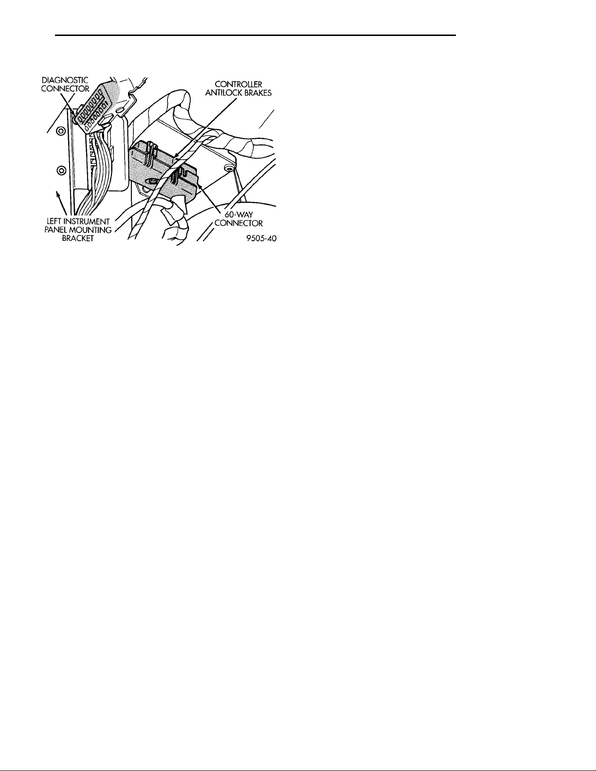
PL BRAKES 5 - 73
DESCRIPTION AND OPERATION (Continued)
ABS WARNING LAMP FUNCTION AND LOCATION
The ABS system uses an Amber ABS Warning
Lamp, located in the instrument cluster. The purpose
of the warning lamp is discussed in detail below.
The ABS warning lamp will turn on when the CAB
detects a condition which results in a shutdown of
ABS function. The ABS Warning Lamp is normally
on until the CAB completes its self tests and turns
the lamp off (approximately 5 seconds after the ignition switch is turned on). When the ABS warning
lamp is on, only the ABS function of the brake system if affected. The standard brake system and the
ability to stop the car will not be affected when only
the ABS warning lamp is on.
ABS BRAKING MODE HYDRAULIC CIRCUIT
Fig. 8 Location Of Controller Antilock Brake (CAB)
CAB continues to control pressure in individual
hydraulic circuits until a locking tendency is no
longer present.
The ABS system is constantly monitored by the
CAB for proper operation. If the CAB detects a fault,
it will turn on the Amber ABS Warning Lamp and
disable the ABS braking system. The normal Non
ABS braking system will remain operational.
The CAB contains a self-diagnostic program which
will turn on the Amber ABS Warning Lamp when a
ABS system fault is detected. Faults are then stored
in a diagnostic program memory. There are multiple
fault messages which may be stored in the CAB and
displayed through the DRB. These fault messages
will remain in the CAB memory even after the ignition has been turned off. The fault messages can be
cleared by using the DRB diagnostics tester, or they
will be automatically cleared from the memory after
the vehicle is driven approximately 3500 miles.
SOLENOID AND VALVE FUNCTION
Through the following operation descriptions the
function of the various hydraulic control valves in the
ABS system will be described. The fluid control
valves mentioned below, control the flow of pressurized brake fluid to the wheel brakes during the different modes of ABS braking.
For explanation purposes we will assume all speed
sensors are sending the same wheel speed information, requiring the same hydraulic fluid modulation
at the same rate.
NORMAL BRAKING BUILD/DECAY VALVE FUNCTION
BUILD/DECAY VALVES OPEN
The brake pedal is applied. The travel of the brake
pedal closes primary and secondary circuits from the
master cylinder fluid supply. Brake fluid from the
primary and secondary circuits flows through the
build/decay valves to the wheel brakes.
CONTROLLER ANTILOCK BRAKE INPUTS
• Four wheel speed sensors.
• Stop lamp switch.
• Ignition switch.
• System relay voltage.
• Ground.
• Pump/Motor Relay Monitor
• Diagnostics Communications
CONTROLLER ANTILOCK BRAKE OUTPUTS
• 4 Decay Solenoids
• ABS warning lamp.
• System relay actuation.
• Diagnostic communication.
• Pump motor relay actuation
ABS BRAKING-DECAY MODE-DECAY
SOLENOID FUNCTION
DECAY SOLENOID ENERGIZED
This will allow brake hydraulic pressure to be
dumped to the HCU sump. At the HCU sump, the
brake hydraulic fluid is picked up by the pump and
restored to high pressure for the next build cycle.
ABS BRAKING-BUILD MODE-DECAY
SOLENOID FUNCTION
DECAY SOLENOID DE-ENERGIZED
Decayed brake fluid, is picked up by the pump in
the HCU and restored to high pressure. This high
pressure brake fluid causes the shuttle valve in the
HCU to actuate, routing high pressure brake fluid
through the build orifice. Routing the high pressure
brake fluid through the build orifice allows for a controlled build pressure in the brakes hydraulic system.
High pressure brake fluid from the build orifice then
Page 74
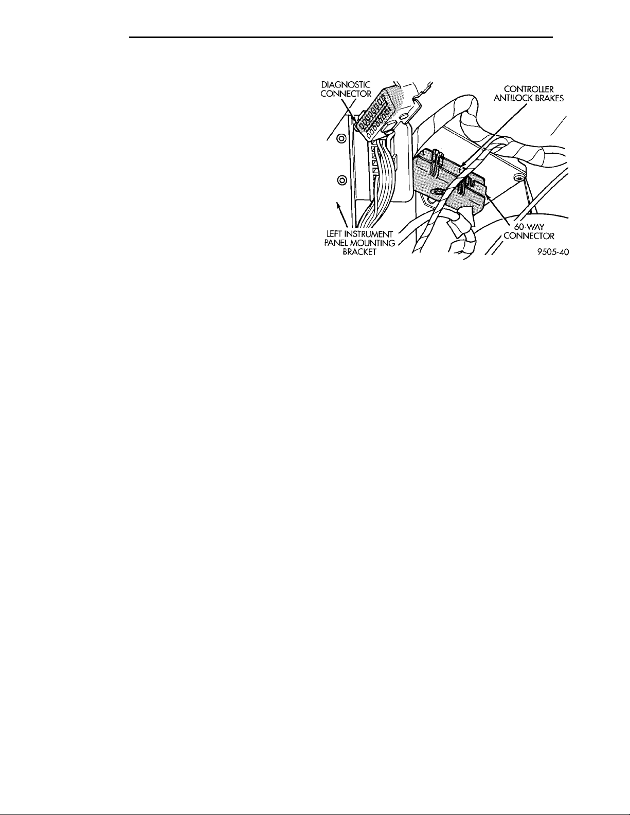
5 - 74 BRAKES PL
DESCRIPTION AND OPERATION (Continued)
passes through the de-energized decay solenoid and
to the wheel brakes to restore braking pressure.
DIAGNOSIS AND TESTING
ABS GENERAL DIAGNOSTICS INFORMATION
This section contains information necessary to
diagnose and test the Bendix ABX-4 Brake System.
Specifically, this section should be used to help diagnose conditions which result in any of the following:
• ABS Warning Lamp turned on.
• Brakes Lock on Hard Application
Diagnosis of base brake conditions which are obviously mechanical in nature should be directed to
Group 5 Brakes in this service manual. This includes
brake noise, brake pulsation, lack of power assist,
parking brake, Red BRAKE Warning Lamp lighting,
or vehicle vibration during normal braking.
Many conditions that generate customer complaints may be normal operating conditions, but are
judged to be a problem due to not being familiar with
the ABS system. These conditions can be recognized
without performing extensive diagnostic work, given
adequate understanding of the operating principles
and performance characteristics of the ABS system.
See the ABS System Operation section in this group
of the service manual to familiarize yourself with the
operating principles of the ABS system.
DIAGNOSTICS MANUAL INFORMATION
Detailed procedures for diagnosing specific ABS
conditions are covered in the Bendix ABX-4 diagnostics manual. The following information is presented
to give the technician a general background on the
diagnostic capabilities of the ABX-4 ABS system.
Please refer to the above mentioned manual for any
further electronic diagnostics and service procedures
that are required on the Bendix ABX-4 Brake System.
DIAGNOSTIC TESTER (DRB)
The Allied Signal ABX-4 Antilock Brake System
diagnostics are performed using the DRB scan tool.
Refer to the Allied Signal ABX-4 diagnostic manual
for the proper testing procedures and the DRB operators manual for its proper operational information
when diagnosing this brake system.
Fig. 9 ABS System Diagnostic Connector Location
SELF DIAGNOSTICS INFORMATION
The ABX-4 system is equipped with a self diagnostic capability which may be used to assist in isolation
of ABS faults. The features of the self diagnostics
system are described below.
START-UP CYCLE
The self diagnostic ABS start up cycle begins when
the ignition switch is turned to the on position. Electrical checks are completed on ABS components, such
as the Controller, decay solenoid continuity, and the
system relay operation. During this check the Amber
ABS Warning Light is turned on for approximately 5
seconds.
DRIVE-OFF CYCLE
Further Functional testing is accomplished once
the vehicle is set in motion and reaches a speed of
about 7 mph. This cycle is performed only once after
each ignition on/off cycle.
• The solenoid valves and the pump/motor are
activated briefly to verify function. If the brake pedal
is applied at this time, the test is bypassed.
• The wheel speed sensor output is verified to be
within the correct operating range.
ONGOING TESTS
Other tests are performed on a continuous basis.
These include checks for decay solenoid continuity,
wheel speed sensor continuity and wheel speed sensor output.
DRB DIAGNOSTIC CONNECTOR
On this vehicle, the ABX-4 brake system (DRB)
diagnostic connector is located under the steering column cover, directly below the steering column (Fig.
9). The ABX-4 system uses the ISO 9141-K connector
which is shared by other vehicle diagnostic systems
such as the powertrain control module and air bag.
DIAGNOSTIC TROUBLE CODE INFORMATION
Fault codes are kept in the controller’s memory
until either erased by the technician using the DRB
or erased automatically after the vehicle has been
driven 3500 miles. Fault codes are retained by the
controller even if the ignition is turned off or the battery is disconnected. The only fault that will not be
Page 75
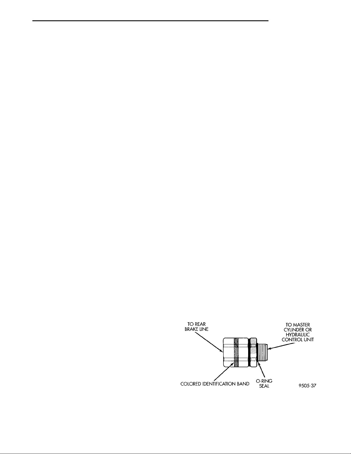
PL BRAKES 5 - 75
DIAGNOSIS AND TESTING (Continued)
erased automatically is the (CAB) fault. A (CAB)
fault can only be erased by the technician using the
DRB diagnostic tester. More than one fault can be
stored at a time. The number of miles the vehicle has
been driven since the most recent fault was stored is
also displayed. Most functions of the (CAB) and ABS
system can be accessed by the technician for testing
and diagnostic purposes by using the DRB.
LATCHING VERSUS NON-LATCHING ABS FAULTS
Some faults detected by the CAB are latching; the
fault is latched and ABS braking is disabled until the
ignition switch is reset. Thus ABS braking is non
operational even if the original fault has disappeared. Other faults are non-latching; any warning
lights that are turned on, are only turned on as long
as the fault condition exists. As soon as the condition
goes away, the ABS Warning Light is turned off,
although a fault code will be set in most cases.
INTERMITTENT DIAGNOSTIC TROUBLE CODES
As with virtually any electronic system, intermittent faults in the ABS system may be difficult to
accurately diagnose.
Most intermittent faults are caused by faulty electrical connections or wiring. When an intermittent
fault is encountered, check suspect circuits for:
(1) Poor mating of connector halves or terminals
not fully seated in the connector body.
(2) Improperly formed or damaged terminals. All
connector terminals in a suspect circuit should be
carefully reformed to increase contact tension.
(3) Poor terminal to wire connection. This requires
removing the terminal from the connector body to
inspect.
(4) Pin presence in the connector assembly
(5) Proper ground connections. Check all ground
connections for signs of corrosion, tight fasteners, or
other potential defects. Refer to wiring diagram manual for ground locations.
(6) If a visual check does not find the cause of the
problem, operate the car in an attempt to duplicate
the condition and record the Fault code.
(7) Most failures of the ABS system will disable
ABS function for the entire ignition cycle even if the
fault clears before key-off. There are some failure
conditions, however, which will allow ABS operation
to resume during the ignition cycle in which a failure
occurred if the failure conditions are no longer
present. The following conditions may result in intermittent illumination of the ABS Warning Lamp. All
other failures will cause the lamp to remain on until
the ignition switch is turned off. Circuits involving
these inputs to the (CAB) should be investigated if a
complaint of intermittent warning system operation
is encountered.
(8) Low system voltage. If Low System Voltage is
detected by the CAB, the CAB will turn on the ABS
Warning Lamp until normal system voltage is
achieved. Once normal voltage is seen at the CAB,
normal operation resumes.
(9) Additionally, any condition which results in
interruption of electrical current to the CAB or modulator assembly may cause the ABS Warning Lamp
to turn on intermittently.
TONEWHEEL INSPECTION
Carefully inspect tonewheel at the suspected faulty
wheel speed sensor for missing, chipped or broken
teeth, this can cause erratic speed sensor signals.
Tonewheels should show no evidence of contact
with the wheel speed sensors. If contact was made,
determine cause and correct before replacing the
wheel speed sensor.
Excessive runout of the tonewheel can cause
erratic wheel speed sensor signals. Refer to Tonewheel Runout in the Specification Section in this section of the service manual for the tonewheel runout
specification. Replace drive shaft assembly or rear
hub/bearing assembly if tonewheel runout exceeds
TO REAR BRAKE LINE TO MASTER CYLINDER ORHYDRAULIC CONTROL UNITO-RING SEALCOLORED IDENTIFI-CATION BAND
the specification.
Inspect tonewheels for looseness on their mounting
surfaces. Tonewheels are pressed onto their mounting
surfaces and should not rotate independently from
the mounting surface.
Check the wheel speed sensor head alignment to
the tone wheel. Also check the gap between the speed
sensor head and the tone wheel to ensure it is at
specification. Refer to Wheel Speed Sensor Clearance
in the Specification Section in this section of the service manual.
PROPORTIONING VALVES
CAUTION: Proportioning valves (Fig. 10) should
never be disassembled.
Fig. 10 Proportioning Valve
If premature rear wheel ABS cycling occurs on a
hard brake application, it could be an indication that
Page 76

5 - 76 BRAKES PL
DIAGNOSIS AND TESTING (Continued)
a malfunction has occurred with one of the proportioning valves.
One proportioning valve controls the right rear
brake, and the other proportioning valve controls the
left rear brake.
If a malfunctioning proportioning valve is suspected on a vehicle equipped with the Bendix ABX-4
ABS Brake System, refer to Proportioning Valve Test
With ABS Brakes in the Base Brake Diagnosis And
Testing Section in this group of the service manual.
BRAKE FLUID CONTAMINATION
Indications of fluid contamination are swollen or
deteriorated rubber parts.
Swollen rubber parts indicate the presence of
petroleum in the brake fluid.
To test for contamination, put a small amount of
drained brake fluid in clear glass jar. If fluid separates into layers, there is mineral oil or other fluid
contamination of the brake fluid.
If brake fluid is contaminated, drain and thoroughly flush system. Replace master cylinder, proportioning valve, caliper seals, wheel cylinder seals,
Antilock Brakes hydraulic unit and all hydraulic
fluid hoses.
VEHICLE TEST DRIVE INFORMATION AND PROCEDURE
Most ABS complaints will require a test drive as a
part of the diagnostic procedure. The purpose of the
test drive is to duplicate the condition.
NOTE: Remember conditions that result in the
turning on of the Red BRAKE Warning Lamp may
indicate reduced braking ability. The following procedure should be used to test drive an ABS complaint vehicle.
Before test driving a brake complaint vehicle, note
whether the Red Brake Warning Lamp or Amber
ABS Warning Lamp is turned on. If it is the Red
Brake Warning Lamp, refer to the hydraulic system
section in the brake group of this manual. If the ABS
Warning lamp was/is on, test drive the vehicle as
described below, to verify the complaint. While the
ABS Warning Lamp is on, the ABS system is not
functional. The standard brake system and the ability to stop the car is not be affected if only the ABS
Warning Lamp is on.
(1) Turn the key to the off position and then back
to the on position. Note whether the ABS Warning
Lamp continues to stay on. If it does, refer to the
ABX-4 Diagnostic Manual for the required test procedures.
(2) If the ABS Warning Lamp goes out, shift into
gear and drive the car to a speed of 5 mph to complete the ABS start up cycle. If at this time the ABS
Warning Lamp goes on refer to the ABX-4 Diagnostic
Manual.
(3) If the ABS Warning Lamp remains OUT, drive
the vehicle a short distance. During this test drive be
sure that the vehicle achieves at least 25 mph. Brake
to at least one complete stop and again accelerate to
25 mph.
(4) If a functional problem with the ABS system is
determined while test driving a vehicle, refer to the
ABX-4 Diagnostics Manual for required test procedures and proper use of the DRB tester.
ABS SERVICE PRECAUTIONS
The ABS uses an electronic control module, the
CAB. This module is designed to withstand normal
current draws associated with vehicle operation.
Care must be taken to avoid overloading the CAB
circuits. In testing for open or short circuits, do
not ground or apply voltage to any of the circuits unless instructed to do so for a diagnostic
procedure. These circuits should only be tested
using a high impedance multi-meter or the DRB
tester as described in this section. Power should
never be removed or applied to any control module
with the ignition in the ON position. Before removing
or connecting battery cables, fuses, or connectors,
always turn the ignition to the OFF position.
CAUTION: Use only factory wiring harnesses. Do
not cut or splice wiring to the brake circuits. The
addition of after-market electrical equipment (car
phone, radar detector, citizen band radio, trailer
lighting, trailer brakes, ect.) on a vehicle equipped
with antilock brakes may affect the function of the
antilock brake system.
SERVICE PROCEDURES
BRAKE FLUID LEVEL INSPECTION
CAUTION: Use only Mopar brake fluid or an equivalent from a tightly sealed container. Brake fluid
must conform to DOT 3 specifications. Do not use
petroleum-based fluid because seal damage in the
brake system will result.
For the specific procedure covering the inspection
of the brake fluid level and adding brake fluid to the
reservoir, refer to the Service Adjustments Section in
this group of the service manual.
BLEEDING PROCEDURE INFORMATION
The base brake system must be bled anytime air is
permitted to enter the hydraulic system, due to disconnection of brake tubes, hoses or components. The
Page 77
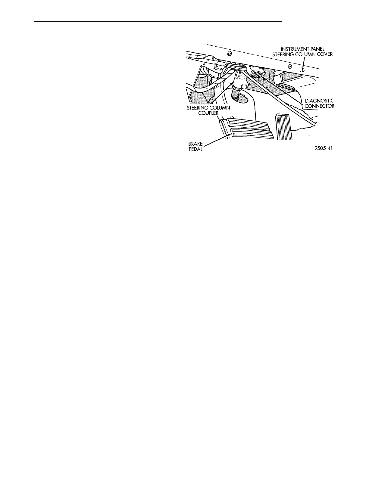
PL BRAKES 5 - 77
SERVICE PROCEDURES (Continued)
ABS system, particularly the HCU, should only be
bled when the HCU is replaced or removed from the
vehicle, or if there is reason to believe the HCU has
ingested air. Under most circumstances that would
require brake bleeding, only the base brake system
needs to be bled.
It is important to note that excessive air in the
brake system will cause a soft or spongy feeling
brake pedal.
During bleeding operations, be sure that the brake
fluid level remains close to the FULL level in the reservoir. Check the fluid level periodically during the
bleeding procedure and add DOT 3 brake fluid as
required.
The Bendix ABX-4 Brake System must be bled as
two independent braking systems. The non ABS portion of the brake system is to be bled the same as
any non ABS system. Refer to the Service Adjustments section in this manual for the proper bleeding
procedure to be used. This brake system can be
either pressure bled or manually bled.
The ABS portion of brake system MUST be bled
separately. This bleeding procedure requires the use
of the DRB Diagnostic tester and the bleeding
sequence procedure outlined below.
ABS BLEEDING PROCEDURE
When bleeding the ABS system, the following
bleeding sequence MUST be followed to insure complete and adequate bleeding. The ABS system can be
bled using a manual bleeding procedure or standard
pressure bleeding equipment.
If the brake system is to be bled using pressure
bleeding equipment, refer to Bleeding Brake System
in the Service Procedure section in the Base Brake
Section in this group of the service manual for proper
equipment usage and procedures.
(1) Assemble and install all brake system components on vehicle making sure all hydraulic fluid lines
are installed and properly torqued.
(2) Connect the DRB Diagnostics Tester to the
diagnostics connector. Located under the steering column cover, directly below the steering column (Fig.
11).
(3) Using the DRB, check to make sure the CAB
does not have any fault codes stored. If it does,
remove them using the DRB.
WARNING: WHEN BLEEDING THE BRAKE SYSTEM WEAR SAFETY GLASSES. A CLEAR BLEED
TUBE MUST BE ATTACHED TO THE BLEEDER
SCREWS AND SUBMERGED IN A CLEAR CONTAINER FILLED PART WAY WITH CLEAN BRAKE
FLUID. DIRECT THE FLOW OF BRAKE FLUID AWAY
FROM THE PAINTED SURFACES OF THE VEHICLE.
BRAKE FLUID AT HIGH PRESSURE MAY COME
OUT OF THE BLEEDER SCREWS WHEN OPENED.
Fig. 11 ABS System Diagnostic Connector Location
(4) Bleed the base brake system using the standard pressure or manual bleeding procedure as outlined in the Service Adjustments section of this
service manual.
(5) Using the DRB, go to the “Bleed ABS” routine.
Apply the brake pedal firmly and initiate the “Bleed
ABS” cycle one time. Release the brake pedal.
(6) Bleed the base brake system again, as in step
Step 4 above.
(7) Repeat steps Step 5 and Step 6 above until
brake fluid flows clear and free of bubbles. Check
brake fluid level in reservoir periodically to prevent
reservoir from running low on brake fluid.
(8) Test drive the vehicle to be sure brake are
operating correctly and that pedal is solid.
REMOVAL AND INSTALLATION
GENERAL SERVICE CAUTIONS
CAUTION: Review this entire section prior to performing any mechanical work on a vehicle equipped
with the Allied Signal ABX- 4 Antilock Brake System. This section contains information on precautions pertaining to potential component damage,
vehicle damage and personal injury which could
result when servicing an ABS equipped vehicle.
CAUTION: Certain components of the ABS System
are not intended to be serviced individually.
Attempting to remove or disconnect certain system
components may result in improper system operation. Only those components with approved
removal and installation procedures in this manual
should be serviced.
Page 78
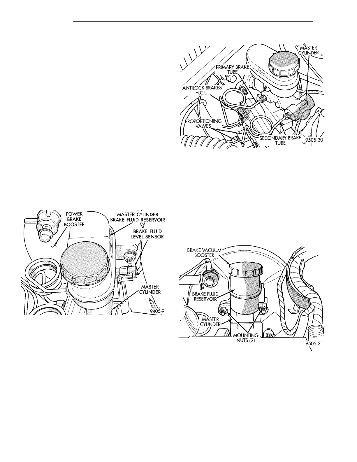
POWER BRAKEBOOSTER MASTER CYLINDER BRAKEFLUID RESERVOIRBRAKE FLUIDLEVEL SENSORMASTER CYLINDER
ANTILOCKBRAKESH.C.U.PRIMARY BRAKE TUBEMASTER CYLINDERPROPOR-TIONINGVALVESSECONDARYBRAKE TUBE
5 - 78 BRAKES PL
REMOVAL AND INSTALLATION (Continued)
CAUTION: Brake fluid will damage painted surfaces. If brake fluid is spilled on any painted surfaces, wash off with water immediately.
The following are general cautions which should be
observed when servicing the ABS system and/or
other vehicle systems. Failure to observe these precautions may result in ABS System component damage.
If welding work is to be performed on the vehicle,
using an electric arc welder, the CAB connector
should be disconnected during the welding operation.
The CAB 60 way connector or the HCU 10 and 6
way connectors should never be connected or disconnected with the ignition switch in the ON position.
BRAKE VACUUMBOOSTERBRAKE FLUIDRESERVOIRMASTERCYL-INDER MOUNTINGNUTS (2)
ABS HYDRAULIC CONTROL UNIT
REMOVE
(1) Disconnect negative (ground) cable from the
battery and isolate cable.
(2) Disconnect vehicle wiring harness connector
from brake fluid level sensor at base of master cylinder brake fluid reservoir (Fig. 12).
Fig. 13 Primary And Secondary Brake Tubes With
ABS Brakes
CAUTION: On ABS equipped vehicles, vacuum in
power booster must be pumped down before
removing master cylinder to prevent the booster
from sucking in any contamination. This can be
done simply by pumping the brake pedal, with the
engine not running, until a firm brake pedal is
achieved.
(5) Remove the 2 nuts (Fig. 14) attaching master
cylinder to power brake booster unit.
Fig. 12 Master Cylinder Brake Fluid Level Sensor
(3) Disconnect primary and secondary brake tubes
from master cylinder housing (Fig. 13). Install plugs
at brake tube outlets of master cylinder assembly.
(4) Clean area where master cylinder attaches to
booster using a suitable brake cleaner.
Fig. 14 Master Cylinder Mounting
(6) Slide master cylinder assembly straight out,
and away from power brake booster unit.
Page 79
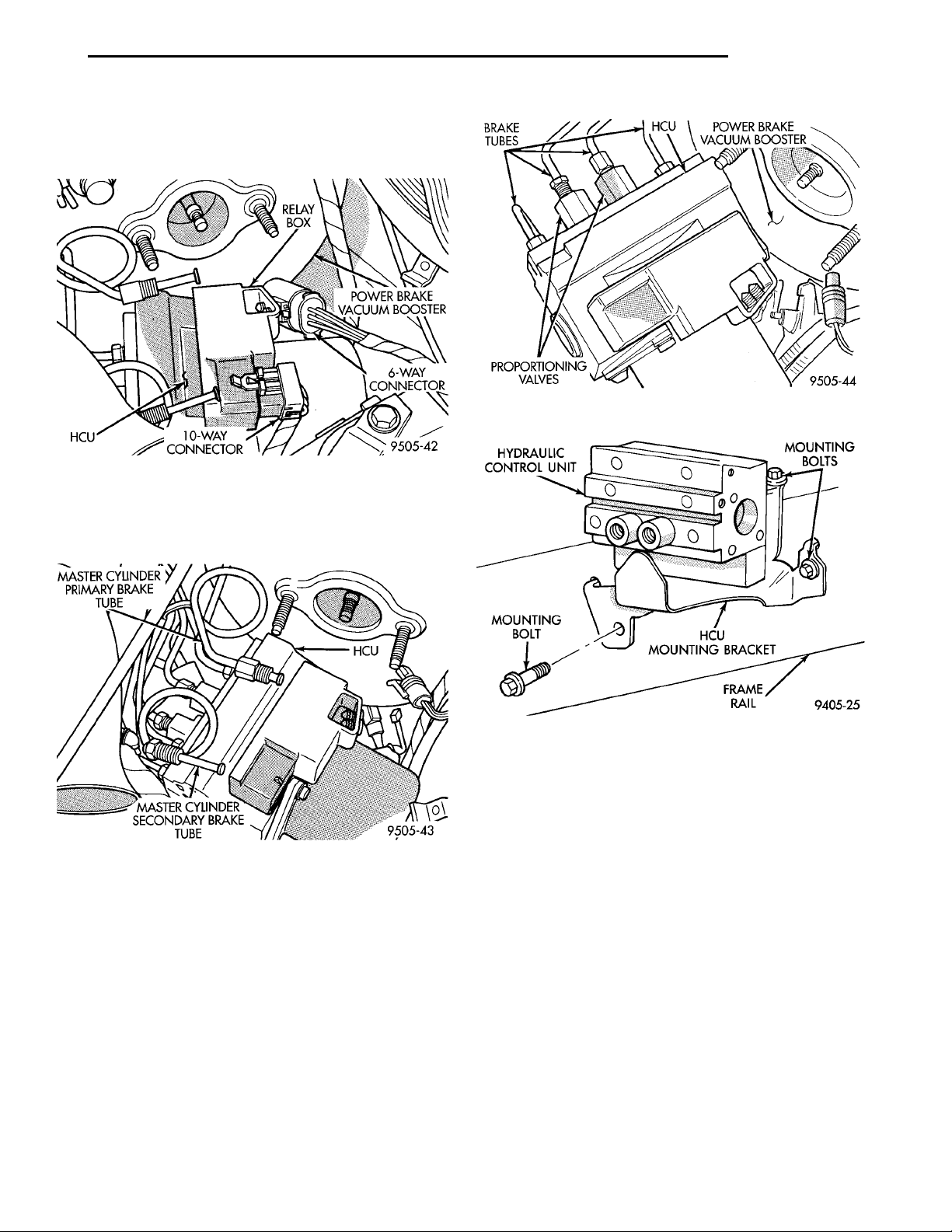
PL BRAKES 5 - 79
REMOVAL AND INSTALLATION (Continued)
(7) Disconnect the 6 way connector from the HCU
wiring harness and 10 way connector from the relay
box located on the HCU (Fig. 15).
MASTER CYLINDERPRIMARY BRAKETUBEMASTER CYLINDERSECONDARY BRAKETUBEHCU
Fig. 15 Electrical Connections To HCU And Relay
(8) Remove the primary and secondary master cylinder brake tubes (Fig. 16) from the HCU.
RELAYBOX POWER BRAKEVACUUM BOOSTER6-WAY CON-NECTOR10-WAY CON-NECTORHCU
Fig. 17 Chassis Brake Tube Connections To HCU
Box
Fig. 16 Primary And Secondary Brake Tubes From
Master Cylinder To HCU
(9) Remove the chassis brake tubes from the proportioning valves and outlet ports of the (HCU) (Fig.
17).
(10) Raise vehicle.
(11) Loosen and remove the 2 bolts attaching the
HCU mounting bracket to the side of the front frame
rail (Fig. 18).
(12) Lower vehicle.
(13) Loosen and remove the bolts attaching the
HCU mounting bracket to the top of the frame rail
(Fig. 18).
(14) Remove HCU and its mounting bracket as an
assembly from the vehicle.
Fig. 18 Hydraulic Control Unit Mounting Bracket
INSTALL
(1) Install the HCU and mounting bracket as an
assembly, on left front frame rail of the vehicle,
aligning tabs on mounting bracket with holes in
frame rail. (Fig. 18).
(2) Install and loosely tighten the bolt attaching
the HCU mounting bracket to the top of the frame
rail.
(3) Raise vehicle.
(4) Install the 2 bolts attaching the HCU mounting
bracket to the side of the front frame rail (Fig. 18).
Then torque both mounting bolts to 28 N·m (200 in.
lbs.).
(5) Lower vehicle.
(6) Torque bolt attaching HCU mounting bracket
to top of frame rail to 20 N·m (180 in. lbs.).
(7) Install the 4 chassis brake tubes (Fig. 17) onto
the proportioning valves and outlet ports of the HCU.
Torque the 4 chassis brake tube nuts to 17 N·m (145
in.lbs.).
Page 80
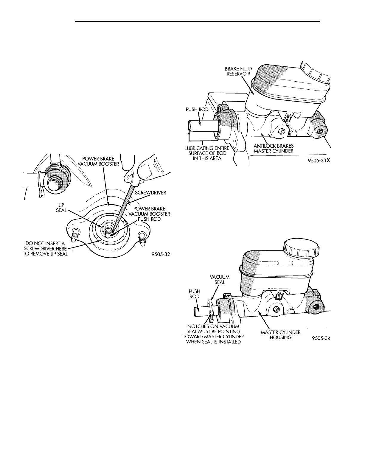
5 - 80 BRAKES PL
REMOVAL AND INSTALLATION (Continued)
(8) Install primary and secondary brake tubes
(Fig. 16) from the master cylinder onto the HCU,
with tube nuts only hand tightened.
(9) Install vehicle wiring harness connectors onto
the 10 way, and 6 way connectors, located on the
relay box of the HCU (Fig. 15).
(10) Remove vacuum seal (Fig. 19) located in the
front of the power brake vacuum booster. Vacuum
seal is removed by carefully inserting a small screw
driver between the push rod of the power brake vacuum booster and vacuum seal (Fig. 19) and pry seal
out of power brake vacuum booster. Do not attempt
to pry seal out of master cylinder by inserting a
tool between seal and power brake vacuum
booster.
Grease—And No Substitutes. Refer to the Mopar
Chemicals Catalog to obtain the required lubricant.
Fig. 20 Lubricating Master Cylinder Push Rod
(13) Install vacuum seal on master cylinder push
rod as shown in (Fig. 21) with notches on vacuum
PUSH ROD VACUUMSEAL MASTER CYLINDER HOUSINGNOTCHES ON VACUUMSEAL MUST BE POINTINGTOWARD MASTER CYLIN-DER WHEN SEAL ISINSTALLED
seal pointing toward master cylinder housing. Then
slide vacuum seal onto master push rod until seal is
seated against master cylinder housing (Fig. 22)
before installing master cylinder on power brake vacuum booster.
Fig. 19 Removing Vacuum Seal From Vacuum
Booster
(11) Remove old vacuum seal from master cylinder,
if the vacuum seal came out of power brake vacuum
booster when master cylinder was removed.
CAUTION: When replacing the master cylinder on
a vehicle equipped with ABS, a NEW vacuum seal
MUST be installed in the power brake vacuum
booster. Use only the procedure detailed below for
installing vacuum seal into power brake vacuum
booster. Be sure old vacuum seal is removed from
power brake vacuum booster before attempting to
install new seal.
CAUTION: When lubricating master cylinder push
rod, use only Mopar Silicone Dielectric Compound.
Using any other type of grease or lubricant on the
push rod, will not provide adequate long term lubrication of the push rod.
(12) Lubricate master cylinder push rod as indicated in (Fig. 20) only using Mopar Dielectric
Fig. 21 Installing Vacuum Seal On Master Cylinder
Push Rod
CAUTION: If vehicle is equipped with ABS, be sure
old vacuum seal is removed from power brake vacuum booster before attempting to install master cylinder and NEW vacuum seal. If vacuum seal is not
removed, refer to Master Cylinder Removal in this
section of the service manual for required vacuum
seal removal procedure.
(14) Position master cylinder on studs of power
brake unit, aligning push rod on power brake vacuum booster with master cylinder push rod.
Page 81
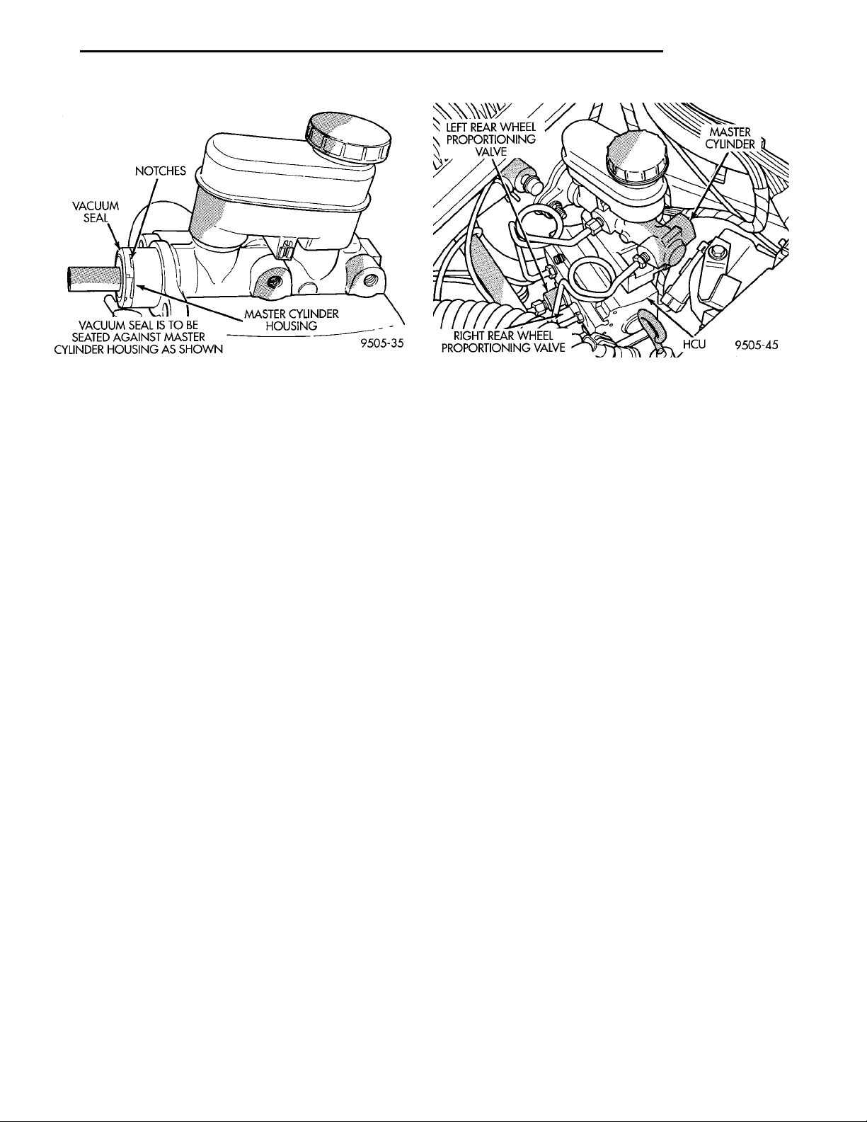
PL BRAKES 5 - 81
REMOVAL AND INSTALLATION (Continued)
Fig. 22 Vacuum Seal Positioned For Installing
Master Cylinder
(15) Install the 2 master cylinder to power brake
unit mounting nuts (Fig. 14) and torque to 28 N·m
(250 in. lbs.) torque.
(16) Connect brake tubes to master cylinder primary and secondary ports (Fig. 13). Torque all tube
nuts to 17 N·m (145 in. lbs.) torque.
(17) Install the wiring harness connector on the
master cylinder reservoir brake fluid level switch
(Fig. 12).
(18) Bleed the base brakes and the ABS brakes
hydraulic systems. Refer to Bleeding Base Brake
Hydraulic System in Service Procedures of the Base
Brake Section and Antilock Brakes Hydraulic System
Bleeding Procedure in Service Procedures of the
Antilock Brake Section for the required procedures.
(19) Road test vehicle to ensure proper operation
of the base and ABS brake systems.
PROPORTIONING VALVES
The HCU does not require removal from the vehicle for the replacement of the proportioning valves.
Use the proportioning valve test procedure in the
Diagnosis And Testing Section in this group of the
service manual to determine which proportioning
valve requires replacement, then replace it using procedure below.
REMOVE
(1) Disconnect the brake tube fitting from the proportioning valve requiring removal from the HCU
(Fig. 23).
(2) Remove proportioning valve (Fig. 23) requiring
replacement, from the HCU.
INSTALL
(1) Wet O-ring seal on new proportioning valve
using clean fresh brake fluid.
Fig. 23 Rear Wheel Proportioning Valve Location On
HCU
(2) Install proportioning valve in HCU and hand
tighten until proportioning is fully installed and
O-ring seal is seated into HCU. Then torque proportioning valve to 40 N·m (30 ft. lbs.).
(3) Install brake tube on proportioning valve.
Tighten tube nut to 17 N·m (145 in. lbs.) torque.
(4) Bleed the base brakes hydraulic system. Refer
to Bleeding Base Brake Hydraulic System in Service
Procedures of the Base Brake Section.
MASTER CYLINDER AND POWER BRAKE BOOSTER
If the Master Cylinder or the Power Booster need
to be serviced or replaced, refer to Master Cylinder
or Power Brake Booster in the Removal And Installation Section in the Base Brake Section of this service manual.
RELAY BOX
The system relay and pump/motor relay are both
serviced together as an assembly with the relay box.
The relay box is mounted directly to the HCU.
To remove the relay box from the HCU, the HCU
requires removal from the vehicle. This is to allow
visual access of the relay box to HCU electrical connection. Visual access to this connection is necessary
to be sure connection is correctly made when installing relay box on the HCU.
REMOVE
(1) Disconnect negative (ground) cable from the
battery and isolate the cable.
(2) Remove the HCU from the vehicle. See
Hydraulic Control Unit in the Removal And Installation Section of the Antilock Brake System Section, in
this group of the service manual, for the required
HCU removal procedure.
(3) Unclip the 6 way wiring harness connector
(Fig. 24) from the relay box.
Page 82
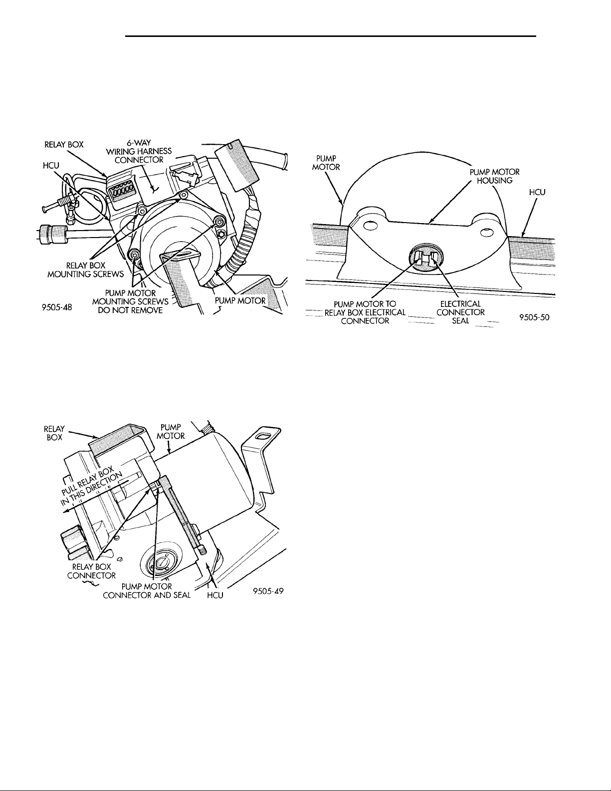
HCU RELAY BOX 6-WAY WIRING HAR-NESS CONNECTOR PUMPMOTORPUMP MOTOR MOUNT-ING SCREWS DO NOTREMOVERELAY BOX MOUNT-ING SCREWS
RELAY BOX PUMPMOTOR HCUPUMP MOTOR CONNECTORAND SEALRELAY BOX CONNECTORPULL RELAY BOXIN THIS DIRECTION
5 - 82 BRAKES PL
REMOVAL AND INSTALLATION (Continued)
(4) Remove the 2 screws (Fig. 24) attaching the
relay box assembly to the HCU. Remove only the 2
screws mounting the relay box to the HCU do
not remove the pump motor mounting screws
(Fig. 24).
Fig. 24 Relay Box To HCU Mounting Screws
(5) Grasp relay box. Without twisting or rocking,
pull relay box away from pump motor housing until
connector on relay box unplugs from the pump motor
terminal (Fig. 25). This is a tight connection,
relay box will require a good amount of force to
unplug from pump motor.
Fig. 25 Relay Box To HCU Electrical Connection
(6) Remove relay box from HCU.
INSTALL
PUMPMOTOR HCUELECTRICAL CONNECTORSEALPUMP MOTOR TO RELAY BOXELECTRICAL CONNECTOR PUMP MOTORHOUSING
(1) Be sure electrical connector seal (Fig. 26) is
installed in pump motor housing before installing
relay box. If electrical connector seal is cracked, brittle or in any way damaged it must be replaced before
installing relay box.
Fig. 26 Pump Motor To Relay Box Electrical
Connection Seal
(2) Position relay box on HCU and carefully align
the terminals on the relay box with the terminals on
the pump motor.
(3) Grasp relay box with both hands. Then without
twisting or rocking, push relay box onto the pump
motor electrical connector as far as possible by hand.
(4) Install and securely tighten the 2 screws (Fig.
24) attaching the relay box assembly to the HCU.
(5) Reconnect the 6 way connector onto the relay
box.
(6) Install the HCU back in the vehicle. See
Hydraulic Control Unit in the Removal And Installation Section of the Antilock Brake System Section, in
this group of the service manual, for the required
HCU installation procedure.
(7) Connect the negative (-) ground cable back on
the negative post of the battery.
(8) Bleed the base brakes and the ABS brakes
hydraulic systems. Refer to Bleeding Base Brake
Hydraulic System in Service Procedures of the Base
Brake Section and Antilock Brakes Hydraulic System
Bleeding Procedure in Service Procedures of the
Antilock Brake Section for the required procedures.
(9) Road test vehicle to ensure proper operation of
the base and ABS systems.
Page 83
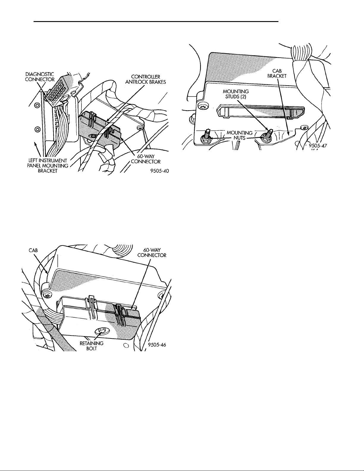
DIAGNOSTICCONNECTOR CONTROLLERANTILOCKBRAKES60-WAY CON-NECTORLEFT INSTRUMENTPANEL MOUNTINGBRACKET
CAB 60–WAY CON-NECTORRETAININGBOLT
MOUNTING STUDS (2) CABBRACKETMOUNTINGNUTS
PL BRAKES 5 - 83
REMOVAL AND INSTALLATION (Continued)
CONTROLLER ANTILOCK BRAKES (CAB)
The CAB is mounted under the instrument panel
on the drivers side kick panel of the vehicle (Fig. 27).
Fig. 29 CAB Bracket To Kick Panel Mounting
INSTALL
(1) Install CAB and mounting bracket on mount-
Fig. 27 Location Of Controller Antilock Brake (CAB)
REMOVE
(1) Turn vehicle ignition off.
(2) Disconnect the wiring harness 60 way connector (Fig. 28) from the Controller Antilock Brake Module (CAB). VERIFY THAT THE VEHICLE
IGNITION IS OFF BEFORE REMOVING THE 60
WAY CONNECTOR.
ing studs located on passenger side kick panel (Fig.
29).
(2) Install the 2 CAB bracket mounting nuts (Fig.
29) and securely tighten.
(3) Install the 60-way wiring harness connector
(Fig. 28) by hand into the 60-way CAB connector, as
far as possible. Then use the CAB connector retaining bolt (Fig. 28) to fully seat wiring harness connector into the CAB.
(4) Torque the 60-way connector retaining bolt
(Fig. 28) to 4 N·m (38 in. lbs.).
(5) If a new CAB is being installed, it must be
initiallized prior to the vehicle being driven.
The CAB is initialized using the DRB Scan Tool
and the initializing procedure described upon
selecting Bendix ABX-4 Diagnostics. New controllers are programmed to flash the ABS warning lamp until initilized by the installing
technician.
Fig. 28 CAB 60-Way Wiring Harness Connector
(3) Remove the 2 controller bracket to drivers side
cowl mounting nuts (Fig. 29).
(4) Remove the CAB from the vehicle.
FRONT WHEEL SPEED SENSOR
NOTE: Proper installation of the Wheel Speed Sensor Cables is critical to continued system operation. Be sure that cables are installed, routed and
clipped properly. Failure to install speed sensor
cables as shown in the on car service section of
this manual, may result in contact with moving
parts or over extension of cables, resulting in an
open circuit.
Page 84
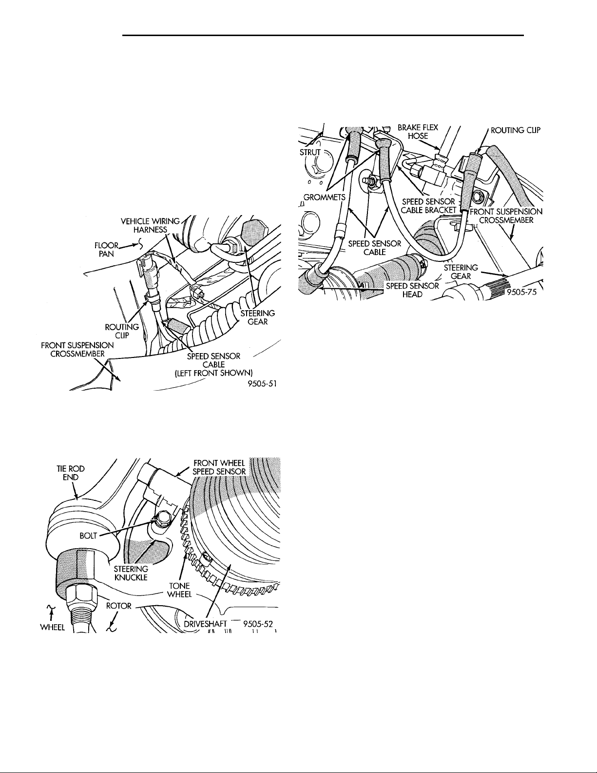
TIE ROD END FRONT WHEEL SPEED SENSORTONE WHEELDRIVESHAFTROTORWHEEL BOLT STEERINGKNUCKLE
FLOOR PANVEHICLE WIRING HAR-NESS STEERINGGEARSPEED SENSOR CABLE (LEFTFRONT SHOWN)FRONT SUSPEN-SION CROSSMEM-BERROUTING CLIP
BRAKE FLEXHOSE ROUTING CLIPFRONT SUSPENSIONCROSSMEMBERSTEERINGGEARSPEED SENSORHEADSPEED SENSORCABLEGROM-METSSTRUT SPEED SENSORCABLE BRACKET
5 - 84 BRAKES PL
REMOVAL AND INSTALLATION (Continued)
REMOVE
(1) Raise vehicle on jack stands or centered on a
frame contact type hoist. See Hoisting in the Lubrication and Maintenance section of this manual, for
the required lifting procedure to be used for this
vehicle.
(2) Remove the tire and wheel assembly from the
vehicle.
(3) Unplug speed sensor cable connector (Fig. 30)
from vehicle wiring harness. Remove clip (Fig. 30)
attaching speed sensor cable connector to vehicle
body.
Fig. 30 Speed Sensor Cable To Wiring Harness
Connection
(4) Remove wheel speed sensor head to steering
knuckle attaching bolt (Fig. 31).
(6) Remove the speed sensor cable assembly grommets from the retaining bracket (Fig. 32). Remove
speed sensor cable routing clip from the frame of the
vehicle (Fig. 32).
Fig. 32 Front Wheel Speed Sensor Cable Routing
INSTALL
(1) Connect the wheel speed sensor cable connector
to the vehicle wiring harness (Fig. 30).
(2) Install the speed sensor cable assembly grommets into the retaining bracket (Fig. 32). Install
speed sensor cable routing clip onto the frame of the
vehicle (Fig. 32).
(3) Install wheel speed sensor to steering knuckle
attaching screw (Fig. 31). Torque the attaching screw
to 7 N·m (60 in. lbs.)
(4) Install the wheel and tire assembly on vehicle.
(5) Road test vehicle to ensure proper operation of
the base and ABS systems.
Fig. 31 Front Wheel Speed Sensor Attaching Bolt
(5) Carefully, remove sensor head from steering
knuckle. If the sensor has seized, due to corrosion,
DO NOT USE PLIERS ON SENSOR HEAD. Use
a hammer and a punch and tap edge of sensor ear,
rocking the sensor side to side until free.
REAR WHEEL SPEED SENSOR
NOTE: Proper installation of the Wheel Speed Sensor Cables is critical to continued system operation. Be sure that cables are installed, routed and
clipped properly. Failure to install speed sensor
cables as shown in the on car service section of
this manual, may result in contact with moving
parts or over extension of cables, resulting in an
open circuit.
REMOVE
(1) Raise vehicle on jack stands or centered on a
frame contact type hoist. See Hoisting in the Lubrication and Maintenance section of this manual, for
the required lifting procedure to be used for this
vehicle.
(2) Remove the tire and wheel from the vehicle.
Page 85
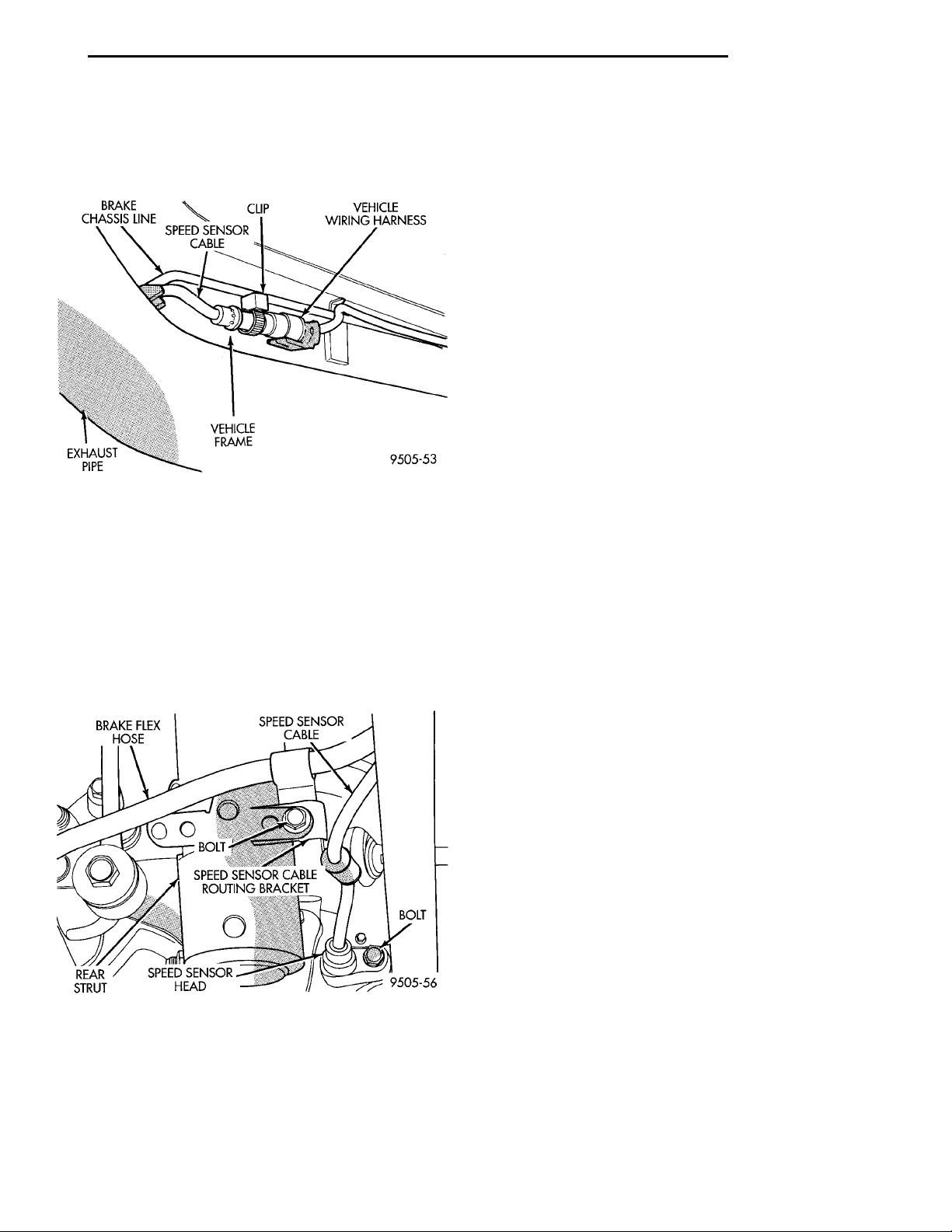
BRAKE CHASSISLINESPEED SENSOR CABLE CLIP VEHICLE WIRING HARNESSVEHICLE FRAMEEXHAUST PIPE
BRAKE FLEXHOSE SPEED SENSORCABLEBOLTSPEED SENSORHEAD
REAR
STRUT
SPEED SENSOR CABLE ROUTING
BRACKET
BOLT
PL BRAKES 5 - 85
REMOVAL AND INSTALLATION (Continued)
(3) Unplug speed sensor cable connector from vehicle wiring harness (Fig. 33). Remove clip (Fig. 33)
attaching speed sensor cable connector to vehicle
body.
Fig. 33 Rear Speed Sensor Connection To Vehicle
Wiring Harness
(4) Remove the speed sensor cable routing bracket
from under rear brake flex hose mounting bracket.
Then remove the speed sensor cable from the routing
clips on the rear brake flex hose and chassis brake
tube.
(5) Remove bolt (Fig. 34) attaching the rear wheel
speed sensor to the disc brake adapter. Then remove
bolt attaching speed sensor cable routing bracket to
rear strut assembly (Fig. 34).
INSTALL
(1) Install wheel speed sensor head into disc brake
adapter (Fig. 34).
(2) Install wheel speed sensor attaching bolt (Fig.
34). Tighten the attaching bolt to a torque of 7 N·m
(60 in. lbs.)
(3) Install the brake flex hose and wheel speed
sensor cable routing bracket on the rear strut
bracket (Fig. 34).
(4) Install wheel speed sensor cable into the routing clips on the rear brake flex hose and chassis
brake tube.
(5) Plug speed sensor cable connector into vehicle
wiring harness (Fig. 33). Install clip (Fig. 33) attaching speed sensor cable connector to vehicle body.
(6) Install the tire and wheel assembly on vehicle.
(7) Road test vehicle to ensure proper operation of
the base and ABS systems.
SPECIFICATIONS
SPEED SENSOR TONE WHEEL RUNOUT
The total indicator runout allowed for both the
front and rear tone wheel measured using a dial indicator is 0.25 mm (.009 in.).
WHEEL SPEED SENSOR TO TONE WHEEL CLEARANCE
FRONT WHEEL
Minimum Clearance .35mm (.014 in.)
Maxamum Clearance 1.2 mm (.047 in.)
Fig. 34 Speed Sensor Head Mounting And Cable
Routing
(6) Remove speed sensor head from the disc brake
adapter. If the speed sensor head has seized in the
adapter, DO NOT USE PLIERS ON SENSOR HEAD.
REAR WHEEL
Minimum Clearance .40mm (.016 in.)
Maxamum Clearance 1.2 mm (.047 in.)
BRAKE FASTENER TORQUE SPECIFICATIONS
DESCRIPTION TORQUE
BRAKE TUBES:
Tube Nuts To Fittings And
Components Except HCU. . . 17 N·m (145 in. lbs.)
From Master Cylinder To HCU
At HCU Ports ...........21N·m(185 in. lbs.)
BRAKE HOSE:
To Caliper Banjo Bolt .........48N·m(35ft.lbs.)
Intermediate Bracket ........12N·m(105 in. lbs.)
MASTER CYLINDER:
To Vacuum Booster
Mounting Nut ...........28N·m(250 in. lbs.)
BRAKE BOOSTER:
To Dash Panel
Mounting Nuts ...........28N·m(250 in. lbs.)
Page 86

5 - 86 BRAKES PL
SPECIFICATIONS (Continued)
DESCRIPTION TORQUE
REAR WHEEL CYLINDER:
To Support Plate
Mounting Bolts ...........13N·m(115in.lbs.)
Bleeder Screw ..............10N·m(80in.lbs.)
BRAKE SUPPORT PLATE:
To Axle Mounting Bolts .......75N·m(55ft.lbs.)
REAR DISC BRAKE ADAPTER:
To Axle Mounting Bolts .......75N·m(55ft.lbs.)
DISC BRAKE CALIPER:
Guide Pin Bolts ............22N·m(192 in. lbs.)
Bleeder Screw .............15N·m(125 in. lbs.)
ABS HYDRAULIC CONTROL UNIT:
To Mounting Bracket Bolts . . . 28 N·m (250 in. lbs.)
Bracket To Frame Rail
Mounting Bolt (Top) .......18N·m(160 in. lbs.)
Bracket To Frame Rail
Mounting Bolts (Side) .....22N·m(200 in. lbs.)
PARKING BRAKE:
Lever Mounting Nuts ........28N·m(250 in. lbs.)
REAR HUB AND BEARING:
To Knuckle Retaining Nut . . . 217 N·m (160 ft. lbs.)
WHEEL:
Stud Lug Nut .......109–150 N·m (80–110 ft. lbs.)
 Loading...