

Page 1
STUB AXLEOUTER C/V JOINT OUTER C/V JOINT BOOT TUNED RUBBER DAMPERWEIGHT INTERCONNECTING SHAFT OUTER C/V JOINT BOOT STUBAXLEOUTER C/V JOINTRIGHT DRIVESHAFTINNER TRIPOD JOINT BOOTINNER TRIPOD JOINTINNER TRIPOD JOINTINNER TRIPOD JOINT BOOTINTERCONNECTING SHAFTLEFT DRIVESHAFT
PL DIFFERENTIAL AND DRIVELINE 3 - 1
DIFFERENTIAL AND DRIVELINE
CONTENTS
page page
GENERAL INFORMATION
FRONT DRIVESHAFT IDENTIFICATION ....... 2
FRONT DRIVESHAFTS ................... 1
DIAGNOSIS AND TESTING
DRIVESHAFT DIAGNOSIS ................. 2
REMOVAL AND INSTALLATION
FRONT DRIVESHAFTS ................... 3
DISASSEMBLY AND ASSEMBLY
DRIVESHAFT RECONDITION .............. 8
GENERAL INFORMATION
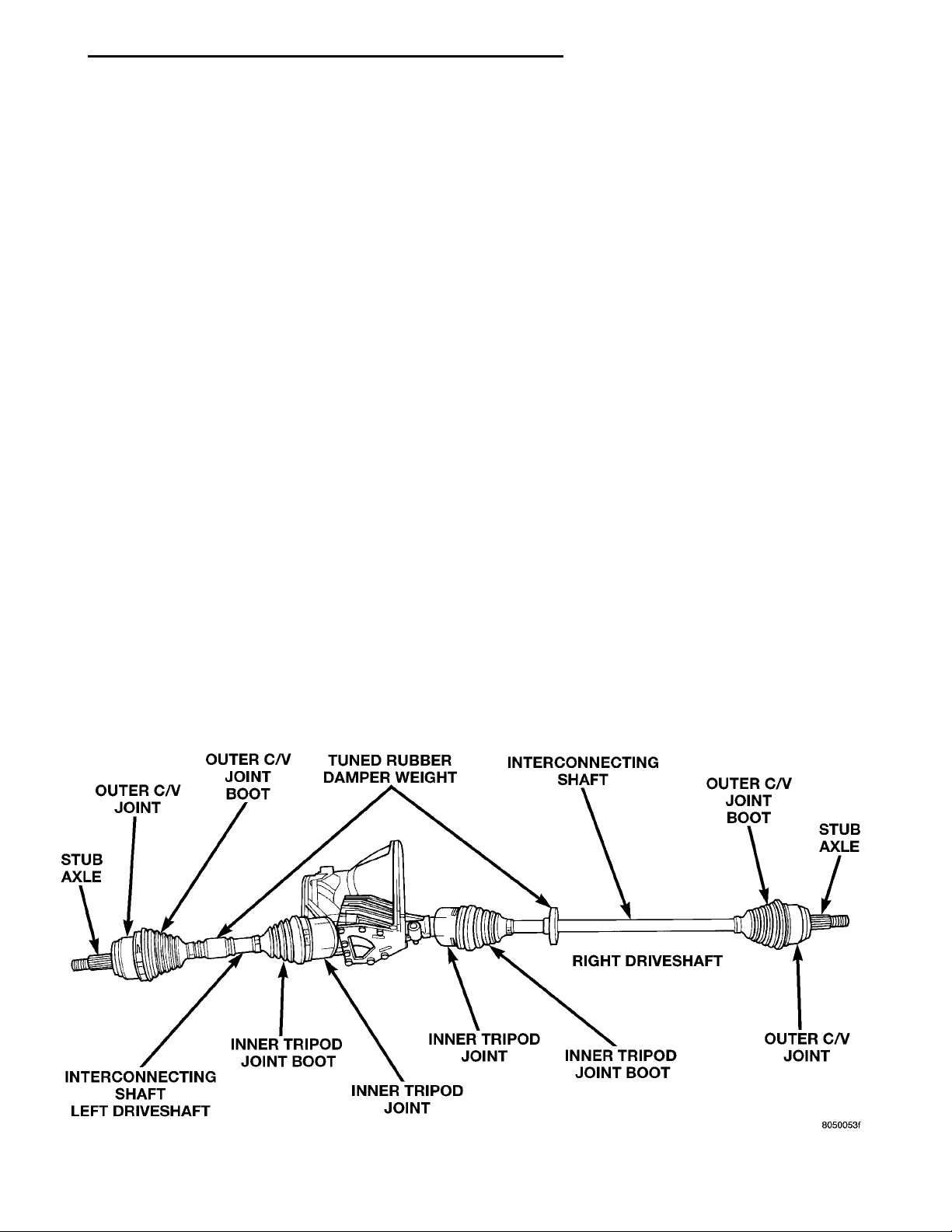
FRONT DRIVESHAFTS
Vehicles equipped with either an automatic or
manual transmission use the unequal–length driveshaft system.
Vehicles equipped with automatic transaxles use a
solid short interconnecting shaft on the left side. The
right side of the vehicle uses a longer solid interconnecting shaft (Fig. 1).
Vehicles equipped with manual transaxles use a
larger diameter (32 mm) short interconnecting shaft
on the left side. The right side uses a longer interconnecting damper (Fig. 1).
INNER TRIPOD JOINT SEAL BOOT .......... 8
OUTER C/V JOINT SEAL BOOT ............ 13
SPECIFICATIONS
TORQUE ............................. 16
SPECIAL TOOLS
DRIVESHAFT .......................... 16
Driveshafts used on both the right and left sides of
the vehicle use a tuned rubber damper weight. The
damper weight applications vary by which side of the
vehicle the driveshaft is located on and the transmission application of the vehicle. When replacing a
driveshaft, be sure the replacement driveshaft has
the same damper weight as the original.
Both driveshaft assemblies use the same type of
inner and outer joints. The inner joint of both driveshaft assemblies is a tripod joint, and the outer joint
of both driveshaft assemblies is a Rzeppa joint. Both
tripod joints and Rzeppa joints are true constant
velocity (C/V) joint assemblies. The inner tripod joint
allows for the changes in driveshaft length through
Fig. 1 Unequal Length Driveshaft System
Page 2
RIGHT SIDE MANUAL TRAN-SAXLE DRIVESHAFT INTERCONNECTING SHAFT TONE WHEEL (ABSONLY)OUTER C/VJOINTSTUB AXLEOUTER C/V JOINTSTUB AXLEMANUAL TRANSAXLE INTERCONNECT-ING SHAFTLEFT SIDE MANUAL TRAN-SAXLE DRIVESHAFTLEFT SIDE AUTOMATICTRANSAXLE DRIVESHAFT INNTER TRIPODJOINT SEALING BOOTTUNEDDAMPERWEIGHT SEALING BOOTAUTOMATIC TRANSAXLEINTERCONNECTING SHAFTINTERCONNECTING SHAFTRIGHT SIDE AUTOMATICTRANSAXLE DRIVESHAFTINNER TRIPODJOINT SEALINGBOOT TUNED DAMPER WEIGHT SEALINGBOOT
3 - 2 DIFFERENTIAL AND DRIVELINE PL
GENERAL INFORMATION (Continued)
the jounce and rebound travel of the front suspension.
On vehicles equipped with ABS brakes, the outer
C/V joint is equipped with a tone wheel used to
determine vehicle speed for ABS brake operation.
The inner tripod joint of both driveshafts is splined
into the transaxle side gears. The inner tripod joints
are retained in the side gears of the transaxle using
a snap ring located in the stub shaft of the tripod
joint. The outer C/V joint has a stub shaft that is
splined into the wheel hub and retained by a hub nut
using a nut lock and cotter pin.
NOTE: This vehicle does not use a rubber–lip bearing seal as on previous front–wheel–drive cars to
prevent contamination of the front wheel bearing.
On these vehicles, the face of the outer C/V joint
fits deeply into the steering knuckle, using a close
outer C/V joint–to–steering knuckle fit. This design
deters direct water splash on bearing seal while
allowing any water that gets in, to run out the bottom of the steering knuckle bearing bore. It is
important to thoroughly clean the outer C/V joint
and the wheel bearing area in the steering knuckle
before it is assembled after servicing.
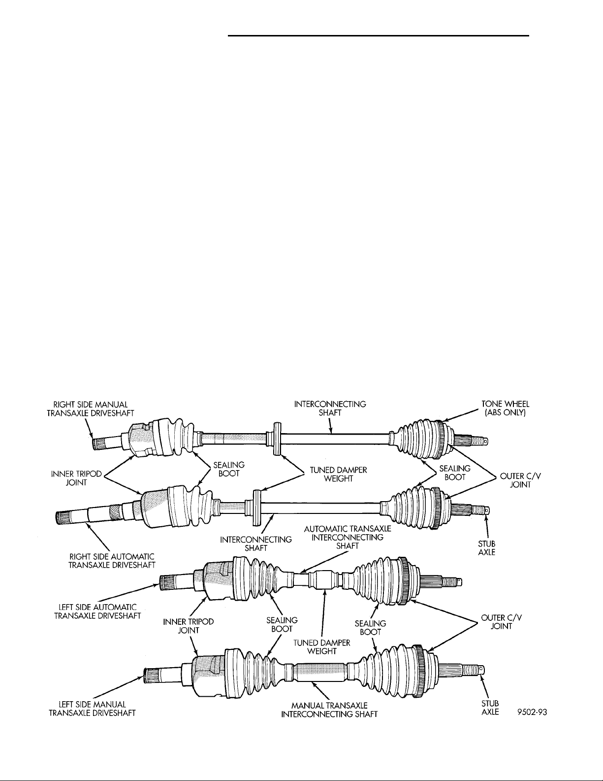
FRONT DRIVESHAFT IDENTIFICATION
Driveshafts and driveshaft inner and outer boots
can be identified as shown in (Fig. 2). Driveshaft boot
location on the driveshaft assemblies is determined
by the number of convolutions on the driveshaft boot.
Refer to (Fig. 2) for the correct location of the sealing
boots.
DIAGNOSIS AND TESTING
DRIVESHAFT DIAGNOSIS
VEHICLE INSPECTION
(1) Check for grease in the vicinity of the inboard
tripod joint and outboard C/V joint; this is a sign of
inner or outer joint seal boot or seal boot clamp damage.
(2) A light film of grease may appear on the right
inner tripod joint seal boot; this is considered normal
and should not require replacement of the seal boot.
The right inner tripod joint seal boot is made of silicone rubber; which will allow the weeping (sweating)
of the joint lubricant to pass through it while in operation.
Fig. 2 Driveshaft Identification
Page 3
PL DIFFERENTIAL AND DRIVELINE 3 - 3
DIAGNOSIS AND TESTING (Continued)
NOISE AND/OR VIBRATION IN TURNS
A clicking noise and/or a vibration in turns could
be caused by one of the following conditions.
(1) Damaged outer C/V or inner tripod joint seal
boot or seal boot clamps. This will result in the loss
and/or contamination of the joint grease, resulting in
inadequate lubrication of the joint.
(2) Noise may also be caused by another component of the vehicle coming in contact with the driveshafts.
CLUNKING NOISE DURING ACCELERATION
This noise may be a result of one of the following
conditions:
(1) A torn seal boot on the inner or outer joint of
the driveshaft assembly.
(2) A loose or missing clamp on the inner or outer
joint of the driveshaft assembly.
(3) A damaged or worn driveshaft C/V joint.
SHUDDER OR VIBRATION DURING ACCELERATION
(1) A worn or damaged driveshaft inner tripod
joint.
(2) A sticking tripod joint spider assembly (inner
tripod joint only).
(3) Improper wheel alignment. See Wheel Alignment in this group for alignment checking and setting procedures and specifications.
VIBRATION AT HIGHWAY SPEEDS
(1) Foreign material (mud, etc.) packed on the
backside of the wheel(s).
(2) Out of balance front tires or wheels. See Group
22, Wheels And Tires for the required balancing procedure.
(3) Improper tire and/or wheel runout. See Group
22, Wheels And Tires for the required runout checking procedure.
REMOVAL
CAUTION: The driveshaft, when installed, acts as a
bolt and secures the front hub/bearing assembly. If
vehicle is to be supported or moved on its wheels
with a driveshaft removed, install a PROPER–SIZED
BOLT AND NUT through front hub. Tighten bolt and
nut to 183 N·m (135 ft. lbs.). This will ensure that
the hub bearing cannot loosen.
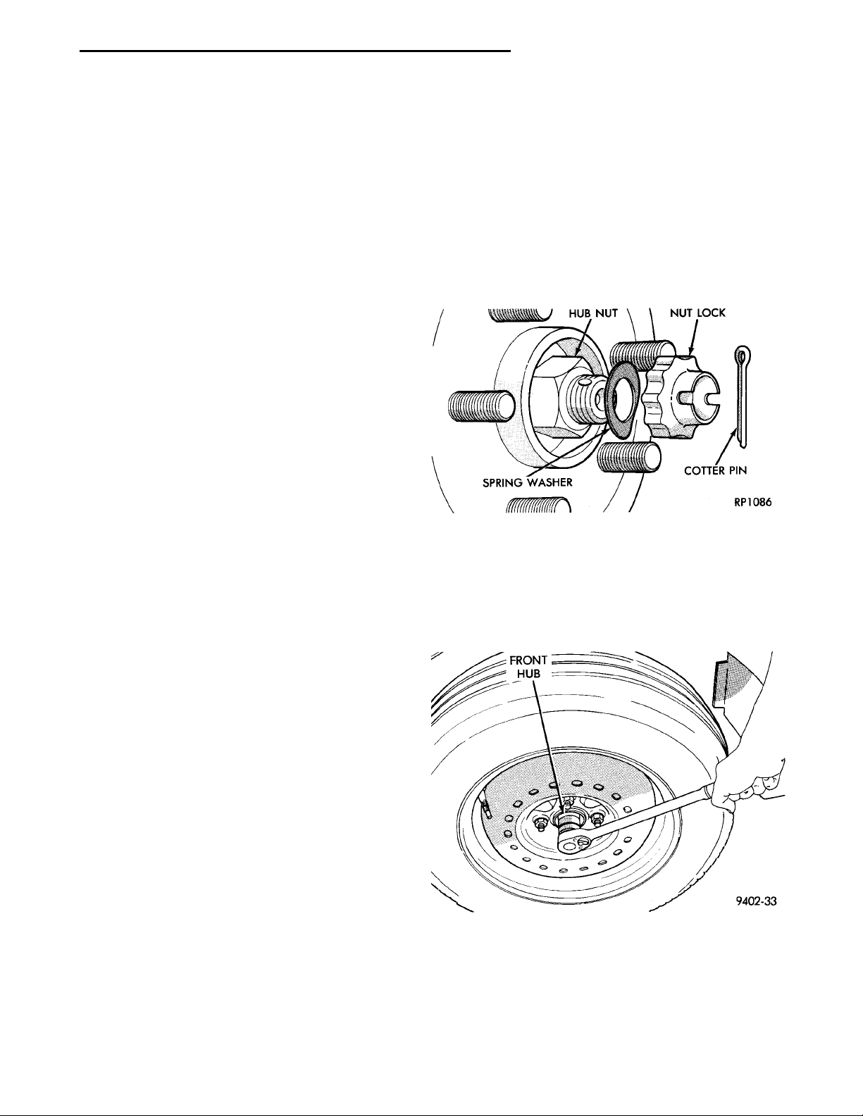
(1) Remove cotter pin, nut lock, and spring washer
(Fig. 3) from the end of the outer C/V joint stub axle.
Fig. 3 Cotter Pin, Nut Lock and Spring Washer
(2) Loosen (but do not remove) stub axle–to–hub/
bearing retaining nut (Fig. 4). Loosen hub nut while
vehicle is on the floor with the brakes applied. The
front hub and driveshaft are splined together and
retained by the hub nut.
REMOVAL AND INSTALLATION
FRONT DRIVESHAFTS
CAUTION: Boot sealing is vital to retain special
lubricants and to prevent foreign contaminants
from entering the C/V joint. Mishandling, such as
allowing the assemblies to dangle unsupported, or
pulling or pushing the ends can cut boots or damage C/V joints. During removal and installation procedures, always support both ends of the driveshaft
to prevent damage.
Fig. 4 Loosening Front Hub Retaining Nut
(3) Raise vehicle on jack stands or centered on a
frame contact–type hoist. See Hoisting in the Lubrication and Maintenance section for required lifting
procedure to be used for this vehicle.
(4) Remove front tire and wheel assembly from the
hub.
Page 4
WIREHANGER STEERINGKNUCKLE BRAKEDISCDISC BRAKE CALIPERASSEMBLY BRAKE HYDRAULICHOSE
BRAKING DISCSTEERINGKNUCKLEDISC BRAKE CALI-PER ASSEMBLY(STORED)
3 - 4 DIFFERENTIAL AND DRIVELINE PL
REMOVAL AND INSTALLATION (Continued)
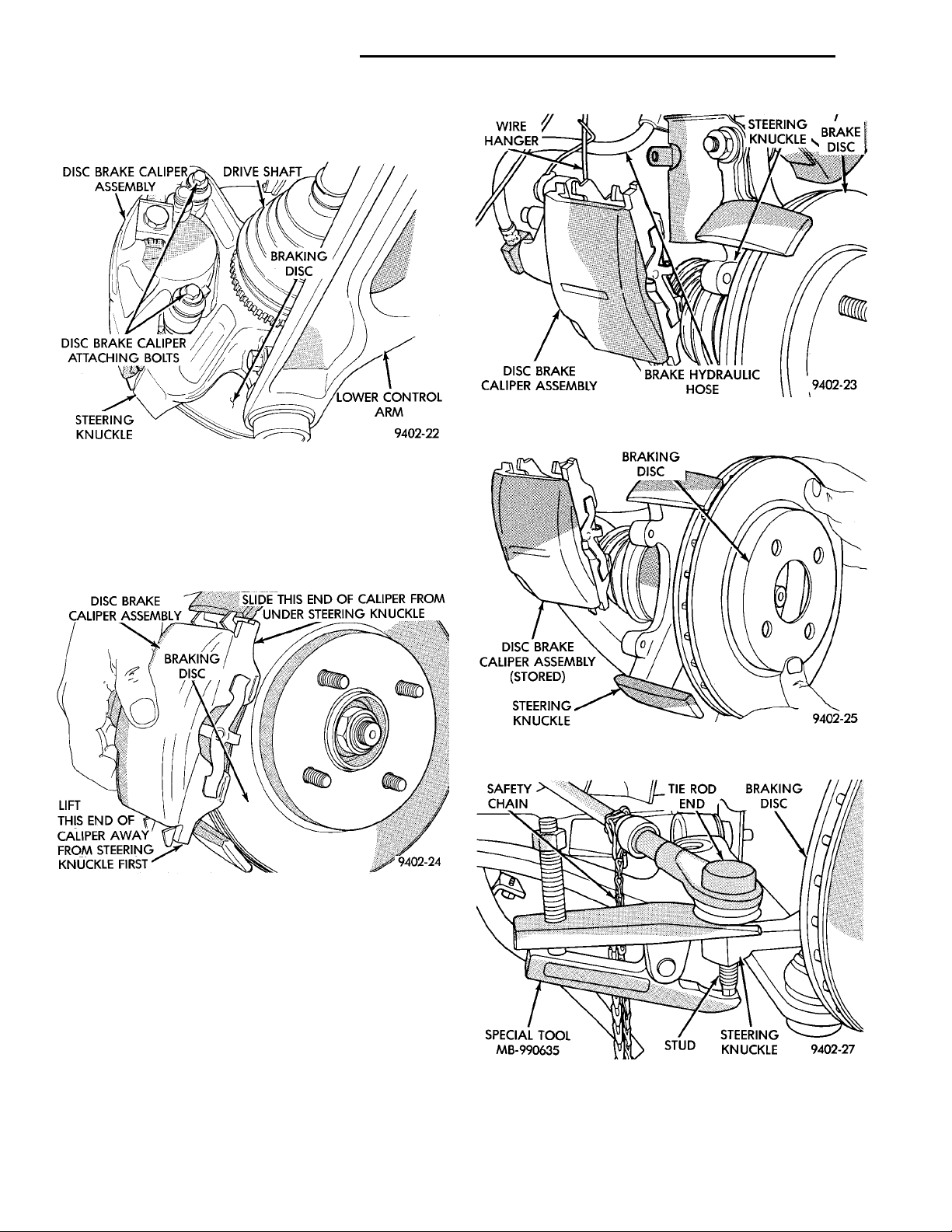
(5) Remove front disc brake caliper assembly to
steering knuckle bolts (Fig. 5).
Fig. 7 Supporting Brake Caliper
Fig. 5 Front Disc Brake Caliper Assembly Bolts
(6) Remove disc brake caliper assembly from steering knuckle. Caliper is removed by first lifting bottom of caliper away from steering knuckle, and then
removing top of caliper out from under steering
knuckle (Fig. 6).
Fig. 6 Brake Caliper Assembly Removal
(7) Support brake caliper/adapter assembly using a
wire hook, not by the brake flex hose (Fig. 7).
(8) Remove braking disc from front hub (Fig. 8).
(9) Remove nut attaching outer tie rod end to
steering knuckle. Nut is to be removed from tie
rod end using the following procedure: Hold tie
rod end stud with a 11/32 socket while loosening and removing nut.
(10) Remove the tie rod end stud from steering
knuckle arm using Special Tool MB-990635 (Fig. 9).
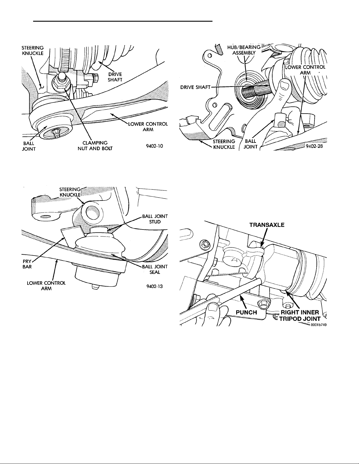
(11) Remove nut and bolt (Fig. 10) retaining ball
joint stud into steering knuckle.
Fig. 8 Removing Front Braking Disc
Fig. 9 Tie Rod End Removal from Steering Knuckle
NOTE: Use caution when separating ball joint stud
from steering knuckle, so ball joint seal does not
get damaged.
Page 5
STEERINGKNUCKLEBALLJOINT DRIVESHAFTCLAMPING NUT AND BOLTLOWER CONTROL ARM
STEERINGKNUCKLEPRY BARLOWER CONTROLARM BALL JOINTSTUDBALL JOINTSEAL
HUB/BEARINGASSEMBLYDRIVESHAFT LOWER CONTROLARMSTEERINGKNUCKLE BALLJOINT
TRANSAXLERIGHT INNER TRI-POD JOINTPUNCH
PL DIFFERENTIAL AND DRIVELINE 3 - 5
REMOVAL AND INSTALLATION (Continued)
Fig. 10 Removing Steering Knuckle Clamp Bolt
(12) Separate ball joint stud from steering knuckle
by prying down on lower control arm (Fig. 11).
Fig. 11 Separate Ball Joint Stud from Steering
Knuckle
NOTE: Care must be taken not to separate the
inner C/V joint during this operation. Do not allow
driveshaft to hang by inner C/V joint, driveshaft
must be supported.
(13) Pull steering knuckle assembly out and away
from outer C/V joint of the driveshaft assembly (Fig.
12).
(14) Support outer end of the driveshaft assembly.
NOTE: Removal of the inner tripod joints is made
easier if you apply outward pressure on the joint as
you strike the punch with a hammer.
Fig. 12 Steering Knuckle Separation from Driveshaft
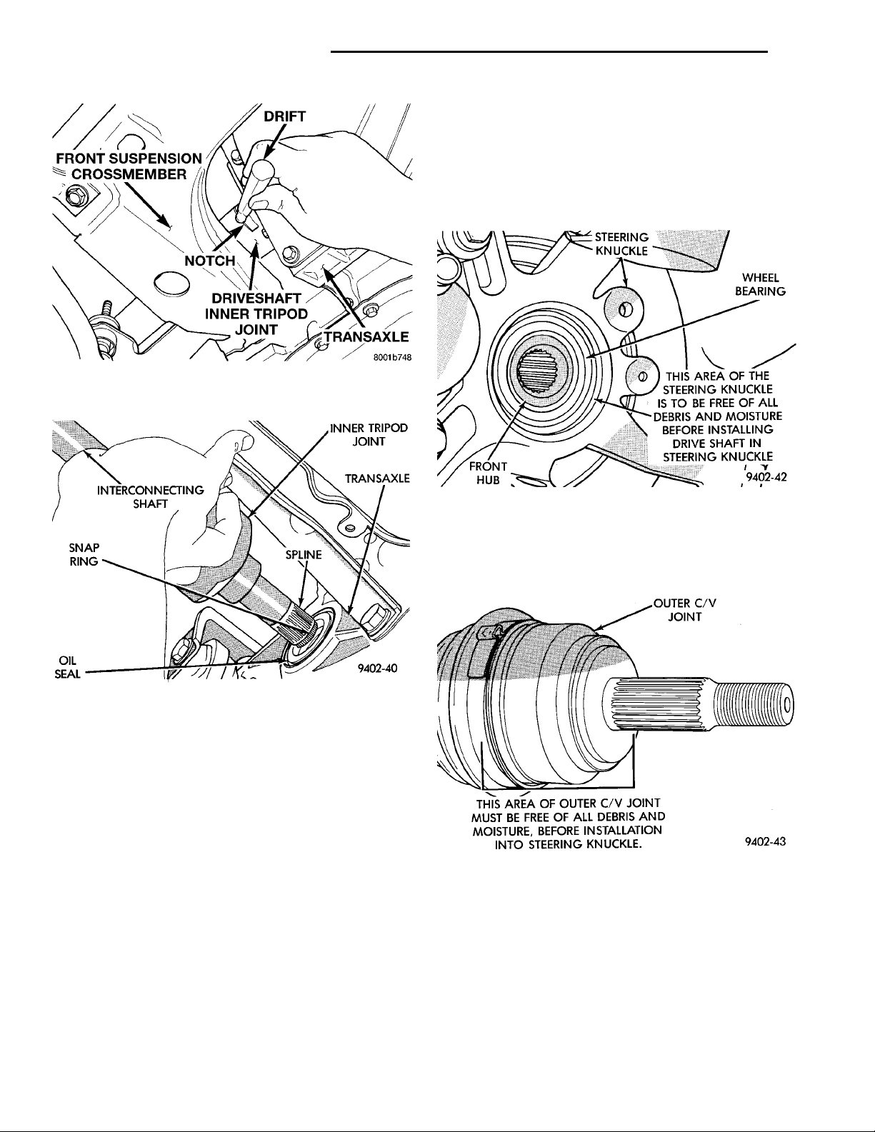
joint, position the punch against the inner tripod
joint (Fig. 13). Strike the punch sharply with a hammer to dislodge the right inner joint from the side
gear. If removing the left side inner tripod joint, position the punch in the groove of the inner tripod joint
(Fig. 14). Strike the punch sharply with a hammer to
dislodge the left inner tripod joint from the side gear.
Fig. 13 Disengaging Right Inner Tripod Joint from
Transaxle
(16) Hold inner tripod joint and interconnecting
shaft of driveshaft assembly (Fig. 15). Remove inner
tripod joint from transaxle by pulling it straight out
of transaxle side gear and transaxle oil seal. When
removing tripod joint, do not let spline or snap
ring drag across sealing lip of the transaxle to
tripod joint oil seal.
(15) Remove the inner tripod joints from the side
gears of the transaxle using a punch to dislodge the
inner tripod joint retaining ring from the transaxle
side gear. If removing the right side inner tripod
Page 6
FRONT SUSPENSIONCROSSMEMBER DRIFT TRANSAXLEDRIVESHAFT INNER TRIPODJOINTNOTCH
INNER TRIPODJOINTTRANSAXLESPLINEOILSEAL SNAP RING INTERCON-NECTINGSHAFT
3 - 6 DIFFERENTIAL AND DRIVELINE PL
REMOVAL AND INSTALLATION (Continued)
fully seated. Test that snap ring is fully engaged
with side gear by attempting to remove tripod
joint from transaxle by hand. If snap ring is
fully engaged with side gear, tripod joint will
not be removable by hand.
(4) Clean all debris and moisture out of steering
knuckle (Fig. 16).
Fig. 14 Disengaging Left Inner Tripod Joint from
Transaxle
STEERINGKNUCKLE WHEEL BEAR-INGFRONT HUB THIS AREA OF THE STEER-ING KNUCKLE IS TO BEFREE OF ALL DEBRIS ANDMOISTURE BEFOREINSTALLING DRIVE SHAFTIN STEERING KNUCKLE
OUTER C/V JOINTTHIS ARE OF OUTER C/V JOINT MUST BEFREE OF ALL DEBRIS AND MOISTURE,BEFORE INSTALLATION INTO STEERINGKNUCKLE.
Fig. 15 Tripod Joint Removal from Transaxle
CAUTION: The driveshaft, when installed, acts as a
bolt and secures the front hub/bearing assembly. If
vehicle is to be supported or moved on its wheels
with a driveshaft removed, install a PROPER–SIZED
BOLT AND NUT through front hub. Tighten bolt and
nut to 183 N·m (135 ft. lbs.). This will ensure that
the hub bearing cannot loosen.
INSTALLATION
(1) Thoroughly clean spline and oil seal sealing
surface, on tripod joint. Lightly lubricate oil seal
sealing surface on tripod joint with fresh clean transmission lubricant.
(2) Holding driveshaft assembly by tripod joint and
interconnecting shaft, install tripod joint into transaxle side gear as far as possible by hand.
(3) Carefully align tripod joint with transaxle side
gears. Then grasp driveshaft interconnecting shaft
and push tripod joint into transaxle side gear until
Fig. 16 Steering Knuckle to C/V Joint Sealing Area
(5) Ensure that front of outer C/V joint, which fits
into steering knuckle (Fig. 17), is free of debris and
moisture before assembling into steering knuckle.
Fig. 17 Outer C/V Joint Inspection
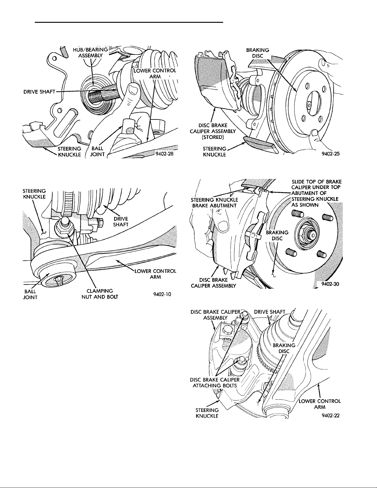
(6) Slide driveshaft back into front hub. Install
steering knuckle onto the ball joint stud (Fig. 18).
(7) Install a NEW steering knuckle to ball joint
stud bolt and nut (Fig. 19). Tighten the nut and bolt
to 95 N·m (70 ft. lbs.).
(8) Install tie rod end into steering knuckle. Start
tie rod end to steering knuckle nut onto stud of tie
rod end. While holding stud of tie rod end stationary,
tighten tie rod end to steering knuckle nut. Then,
Page 7
STEERINGKNUCKLEBALLJOINT DRIVESHAFTCLAMPING NUT AND BOLTLOWER CONTROL ARM
HUB/BEARINGASSEMBLYDRIVESHAFT LOWER CONTROLARMSTEERINGKNUCKLE BALLJOINT
PL DIFFERENTIAL AND DRIVELINE 3 - 7
REMOVAL AND INSTALLATION (Continued)
DISC BRAKE CALIPERASSEMBLY DRIVE SHAFTBRAKINGDISC
STEERINGKNUCKLE LOWER CON-TROL ARM
DISC BRAKE CALIPER
ATTACHING BOLTS
Fig. 18 Driveshaft Installation Into Hub And Steering
Knuckle
Fig. 19 Tighten Steering Knuckle Clamp Bolt
using a crowfoot and 11/32 socket, tighten tie rod end
nut to 61 N·m (45 ft. lbs.).
(9) Install braking disc back on hub and bearing
assembly (Fig. 20).
(10) Install disc brake caliper assembly on steering
knuckle. Caliper is installed by first sliding top of
caliper under top abutment on steering knuckle.
Then installing bottom of caliper against bottom
abutment of steering knuckle (Fig. 21).
(11) Install caliper assembly to steering knuckle
bolts (Fig. 22). Tighten to 31 N·m (23 ft. lbs.).
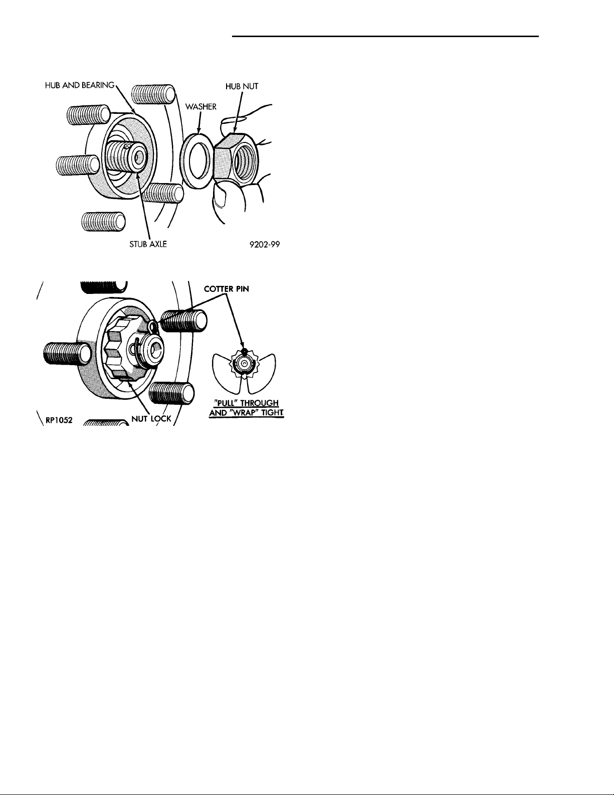
(12) Clean all foreign matter from threads of outer
C/V joint stub axle. Install hub nut and washer onto
the threads of the stub axle and tighten nut (Fig. 23).
(13) With vehicle brakes applied to keep axle shaft
from turning, tighten hub nut to 183 N·m (135 ft.
lbs.).
(14) Install spring washer, nut lock, and cotter pin
on outer C/V joint stub axle (Fig. 24).
STEERINGKNUCKLE BRAKEABUTMENT BRAKINGDISCDISC BRAKE CALIPERASSEMBLY
SLIDE TOP OF BRAKE CALIPER UNDER TOP ABUTMENT OF STEERING
KNUCKLE AS SHOWN
Fig. 20 Installing Braking Disc
Fig. 21 Disc Brake Caliper Assembly Installation
Fig. 22 Front Disc Brake Caliper Assembly Bolts
(15) Install front wheel and tire assembly. Install
front wheel lug nuts and tighten to 135 N·m (100 ft.
lbs.).
Page 8
HUB AND BEAR-ING WASHER HUB NUTSTUBAXLE
COTTER PIN“PULL” THROUGH AND“WRAP” TIGHTNUT LOCK
3 - 8 DIFFERENTIAL AND DRIVELINE PL
REMOVAL AND INSTALLATION (Continued)
See (Fig. 25) for the exploded view of the front
driveshaft components.
INNER TRIPOD JOINT SEAL BOOT
REMOVAL
To remove sealing boot from driveshaft for replacement, the driveshaft assembly must be removed from
the vehicle. See Servicing Driveshaft in this section
for the required driveshaft removal and replacement
procedure.
The inner tripod joints use no internal retention in
the tripod housing to keep the spider assembly in the
housing. Therefore, do not pull on the interconnecting shaft to disengage tripod housing from transmission stub shaft. Removal in this manner will cause
Fig. 23 Front Hub To Stub Shaft Nut Installed
damage to the inboard joint sealing boots.
(1) Remove the driveshaft requiring boot replacement from the vehicle. See Servicing Driveshaft in
this section for the required driveshaft removal procedure.
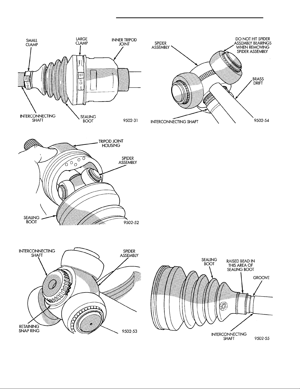
(2) Remove large boot clamp that retains inner tripod joint sealing boot to tripod joint housing (Fig. 26)
and discard. Then remove small clamp that retains
inner tripod joint sealing boot to interconnecting
shaft and discard. Remove the sealing boot from the
tripod housing and slide it down the interconnecting
shaft.
Fig. 24 Spring Washer, Nut Lock And Cotter Pin
Installation
(16) Check for correct fluid level in transaxle
assembly. Refer to Group 21 Transaxle, for the correct fluid level checking procedure for the type of
transaxle being checked.
(17) Lower vehicle.
DISASSEMBLY AND ASSEMBLY
DRIVESHAFT RECONDITION
NOTE: The only service that is to be performed on
the driveshaft assemblies is the replacement of the
driveshaft seal boots.
If any failure of internal driveshaft components is
diagnosed during a vehicle road test or disassembly
of the driveshaft, the driveshaft will need to be
replaced as an assembly.
NOTE: Lubricant requirements and quantities are
different for inner joints than for outer joints. Use
only the recommended lubricants in the required
quantities when servicing driveshaft assemblies.
CAUTION: When removing the spider joint from the
tripod joint housing, hold the rollers in place on the
spider trunions to prevent the rollers and needle
bearings from falling away.
(3) Slide the interconnecting shaft and spider
assembly out of the tripod joint housing (Fig. 27).
(4) Remove snap ring that retains spider assembly
to interconnecting shaft (Fig. 28). Remove the spider
assembly from interconnecting shaft. If spider assembly will not come off interconnecting shaft by hand, it
can be removed by tapping spider assembly with a
brass drift (Fig. 29). Do not hit the outer tripod
bearings in an attempt to remove spider assembly from interconnecting shaft.
(5) Slide sealing boot off interconnecting shaft.
(6) Thoroughly clean and inspect spider assembly,
tripod joint housing, and interconnecting shaft for
any signs of excessive wear. If any parts show
signs of excessive wear, the driveshaft assembly
will require replacement. Component parts of
these driveshaft assemblies are not serviceable.
Page 9
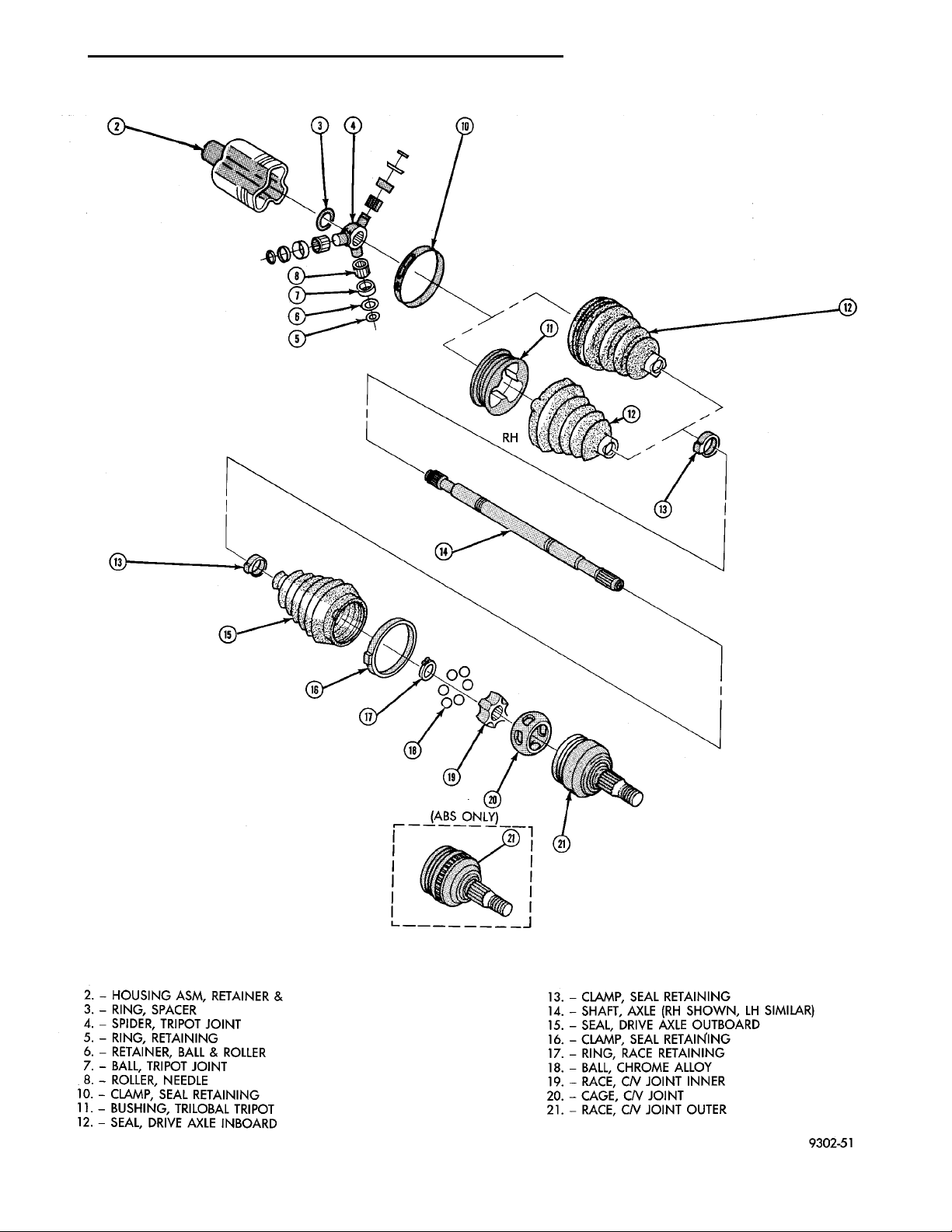
(ABS ONLY)2. — HOUSING ASM, RETAINER &3. — RING, SPACER4. — SPIDER, TRIPOT JOINT5. — RING, RETAINING6. — RETAINER, BALL & ROLLER7. — BALL, TRIPOT JOINT8. — ROLLER, NEEDLE10. — CLAMP, SEAL RETAINING11. — BUSHING, TRILOBAL TRIPOT12. — SEAL, DRIVE AXLE INBOARD 13. — CLAMP, SEAL RETAINING14. — SHAFT, AXLE (RH SHOWN, LH SIMILAR)15. — SEAL, DRIVE AXLE OUTBOARD16. — CLAMP, SEAL RETAINING17. — RING, RACE RETAINING18. — BALL, CHROME ALLOY19. — RACE, C/V JOINT INNER20. — CAGE, C/V JOINT21. — RACE, C/V JOINT OUTER
PL DIFFERENTIAL AND DRIVELINE 3 - 9
DISASSEMBLY AND ASSEMBLY (Continued)
Fig. 25 Driveshaft Assembly Components (Exploded View)
Page 10
SMALLCLAMP LARGE CLAMP INNER TRIPODJOINTSEALING BOOT INTERCON-NECTINGSHAFT
INTERCONNECTINGSHAFT SPIDER ASSEM-BLYRETAININGSNAP RING
TRIPOD JOINTHOUSINGSPIDER ASSEM-BLYSEALINGBOOT
SPIDER ASSEM-BLY DO NOT HIT SPIDERASSEMBLY BEARINGSWHEN REMOVING SPIDERASSEMBLYBRASSDRIFTINTERCONNECTING SHAFT
SEALINGBOOT RAISED BEAD IN THISAREA OF SEALINGBOOT GROOVEINTERCONNECTING SHAFT
3 - 10 DIFFERENTIAL AND DRIVELINE PL
DISASSEMBLY AND ASSEMBLY (Continued)
Fig. 26 Inner Tripod Joint Sealing Boot Clamps
Fig. 27 Spider Assembly Joint Removal from
Housing
Fig. 29 Spider Assembly Removal from
Interconnecting Shaft
INSTALLATION
NOTE: The inner tripod joint sealing boots are
made from two different types of material. High–temperature applications use silicone rubber
whereas standard temperature applications use
Hytrel plastic. The silicone sealing boots are soft
and pliable. The Hytrel sealing boots are stiff and
rigid. The replacement sealing boot MUST BE the
same type of material as the sealing boot that was
removed.
(1) Slide inner tripod joint seal boot retaining
clamp, onto interconnecting shaft. Then slide the
replacement inner tripod joint sealing boot onto
interconnecting shaft. Inner tripod joint seal boot
MUST be positioned on interconnecting shaft,
so the raised bead on the inside of the seal boot
is in groove on interconnecting shaft (Fig. 30).
Fig. 28 Spider Assembly Retaining Snap Ring
Fig. 30 Sealing Boot Installation on Interconnecting
Shaft
Page 11
SPIDER ASSEMBLYINTERCONNECTING SHAFTCHAMFER
DO NOT HIT BEARINGSWHEN INSTALLING THESPIDER ASSEMBLYSPIDER ASSEM-BLYINTERCONNECTINGSHAFTBRASSDRIFT
INTERCONNECTINGSHAFT SPIDER ASSEM-BLYRETAININGSNAP RING
TRIPOD JOINTHOUSINGSPIDER ASSEM-BLYSEALINGBOOT
PL DIFFERENTIAL AND DRIVELINE 3 - 11
DISASSEMBLY AND ASSEMBLY (Continued)
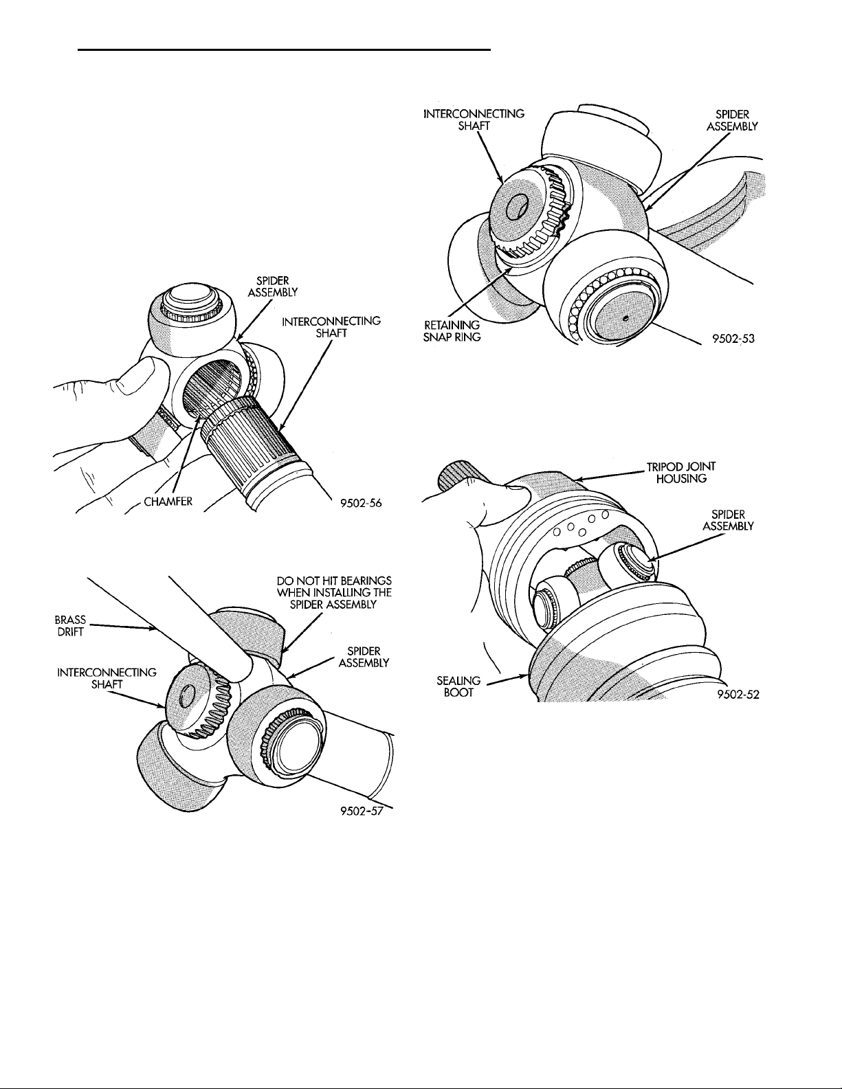
(2) Install spider assembly onto interconnecting
shaft with chamfer on spider assembly toward interconnecting shaft (Fig. 31). Spider assembly must be
installed on interconnecting shaft far enough to fully
install spider retaining snap ring. If spider assembly
will not fully install on interconnecting shaft by
hand, it can be installed by tapping the spider body
with a brass drift (Fig. 32). Do not hit the outer
tripod bearings in an attempt to install spider
assembly on interconnecting shaft.
Fig. 33 Spider Assembly Retaining Snap Ring
Installed
(5) Align tripod housing with spider assembly and
then slide tripod housing over spider assembly and
interconnecting shaft (Fig. 34).
Fig. 31 Spider Assembly Installation on
Interconnecting Shaft
Fig. 32 Installing Spider Assembly On
Interconnecting Shaft
(3) Install the spider assembly to interconnecting
shaft retaining snap ring into groove on end of interconnecting shaft (Fig. 33). Be sure the snap ring is
fully seated into groove on interconnecting shaft.
(4) Distribute 1/2 the amount of grease provided in
the seal boot service package (DO NOT USE ANY
OTHER TYPE OF GREASE) into tripod housing. Put
the remaining amount into the sealing boot.
Fig. 34 Installing Tripod Housing on Spider
Assembly
(6) Install inner tripod joint seal boot to intercon-
necting shaft clamp evenly on sealing boot.
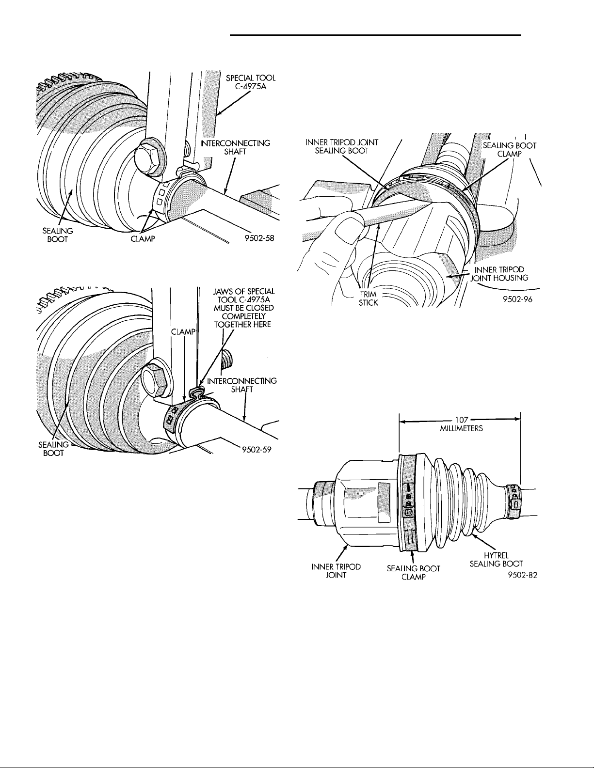
(7) Clamp sealing boot onto interconnecting shaft
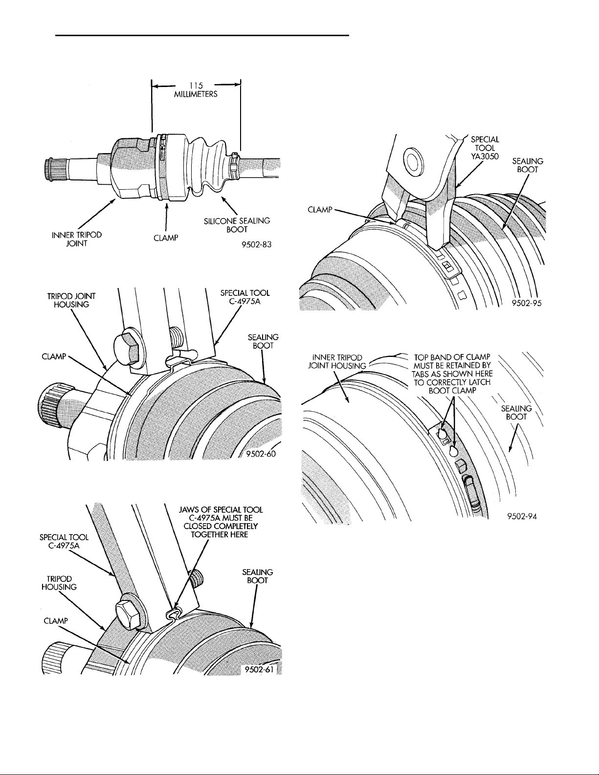
using crimper, Special Tool C-4975-A and the following procedure. Place crimping tool C- 4975-A over
bridge of clamp (Fig. 35). Tighten nut on crimping
tool C- 4975-A until jaws on tool are closed completely together, face to face (Fig. 36).
CAUTION: Seal must not be dimpled, stretched, or
out–of–shape in any way. If seal is NOT shaped correctly, equalize pressure in seal and shape it by
hand.
(8) Position sealing boot into the tripod housing
retaining groove. Install seal boot retaining clamp
evenly on sealing boot.
Page 12
SEALING
BOOT
CLAMP JAWS OF SPECIAL TOOLC-4975A MUST BECLOSED COMPLETELYTOGETHER HEREINTERCONNECTINGSHAFT
SPECIALTOOL C-4975AINTERCON-NECTING SHAFTCLAMPSEALINGBOOT
INNER TRIPOD JOINT SEAL-ING BOOT
107 MILLIME-TERSHYTREL SEALINGBOOTSEALING BOOT CLAMPINNER TRIPODJOINT
INNER TRIPODJOINT HOUSINGTRIM STICK
SEALING BOOT
CLAMP
3 - 12 DIFFERENTIAL AND DRIVELINE PL
DISASSEMBLY AND ASSEMBLY (Continued)
boot can occur. If inner tripod joint has a Hytrel
(hard plastic) sealing boot, be sure trim stick is
inserted between soft rubber insert and tripod housing, and not the hard plastic sealing boot and soft
rubber insert.
Fig. 35 Crimping Tool Installed on Sealing Boot
Clamp
Fig. 36 Sealing Boot Retaining Clamp Installed
CAUTION: The following positioning procedure
determines the correct air pressure inside the inner
tripod joint assembly prior to clamping the sealing
boot to inner tripod joint housing. If this procedure
is not done prior to clamping sealing boot to tripod
joint housing, boot durability can be adversely
affected.
CAUTION: When venting the inner tripod joint
assembly, use care so inner tripod sealing boot
does not get punctured or, in any other way, damaged. If sealing boot is punctured or damaged while
being vented, the sealing boot can not be used.
(9) Insert a trim stick between the tripod joint and
the sealing boot to vent inner tripod joint assembly
(Fig. 37). When inserting trim stick between tri-
pod housing and sealing boot, ensure trim stick
is held flat and firmly against the tripod housing. If this is not done, damage to the sealing
Fig. 37 Trim Stick Inserted for Venting Tripod Joint
(10) With trim stick inserted between sealing boot
and tripod joint housing, position inner tripod joint
on driveshaft until correct sealing boot edge to edge
length is obtained for type of sealing boot material
being used (Fig. 38) (Fig. 39). Then remove the trim
stick.
Fig. 38 Sealing Boot End to End Length with Hytrel
Boot
(11) Clamp tripod joint sealing boot to tripod joint
using required procedure for type of boot clamp
application. If seal boot uses crimp type boot clamp,
clamp sealing boot onto tripod housing using crimper,
Special Tool C-4975-A. Place crimping tool C- 4975-A
over bridge of clamp (Fig. 40). Tighten nut on crimping tool C- 4975-A until jaws on tool are closed completely together, face–to–face (Fig. 41).
Page 13
115 MILLIMETERSSILICONE SEALINGBOOTCLAMPINNER TRIPODJOINT
JAWS OF SPECIAL TOOLC-4975A MUST BE CLOSEDCOMPLETELY TOGETHERHERESEALING BOOTCLAMPTRIPOD HOUS-INGSPECIALTOOL C-4975A
TRIPOD JOINTHOUSINGSPECIALTOOLC-4975ASEALING BOOTCLAMP
INNER TRIPODJOINT HOUSING TOP BANK OF CLAMP MUST BERETAINED BY TABS AS SHOWNHERE TO CORRECTLY LATCHBOOT CLAMPSEALING BOOT
SPECIAL TOOLYA3050SEALING BOOTCLAMP
PL DIFFERENTIAL AND DRIVELINE 3 - 13
DISASSEMBLY AND ASSEMBLY (Continued)
clamp locking tool, Snap-Ont YA3050 (or an equivalent). Place prongs of clamp locking tool in the holes
of the clamp (Fig. 42). Squeeze tool together until top
band of clamp is latched behind the two tabs on
lower band of clamp (Fig. 43).
Fig. 39 Sealing Boot End to End Length with
Silicone Boot
Fig. 40 Crimping Tool Installed on Sealing Boot
Clamp
Fig. 42 Clamping Tool Installed on Sealing Boot
Clamp
Fig. 43 Sealing Boot Clamp Correctly Installed
(13) Install the driveshaft requiring boot replacement back on the vehicle. See Servicing Driveshaft in
this section for the required driveshaft installation
procedure.
Fig. 41 Sealing Boot Retaining Clamp Installed
(12) If seal boot uses low profile latching type boot
clamp, clamp sealing boot onto tripod housing using
OUTER C/V JOINT SEAL BOOT
REMOVAL
To remove outer C/V joint sealing boot from a
driveshaft for replacement, the driveshaft assembly
must be removed from the vehicle. See Servicing
Driveshaft in this section for the required driveshaft
removal and replacement procedure.
(1) Remove driveshaft assembly requiring boot
replacement from vehicle. See Servicing Driveshaft in
Page 14
SMALLCLAMP SEALING BOOT OUTER C/V JOINT HOUSINGLARGE CLAMPINTERCONNECTINGSHAFT
SOFT HAMMER (TAP HOUS-
ING)
WEARSLEEVECIRCLIP (OUTER END OF SHAFT)
SNAP RING PLIERS INTERCONNECTINGSHAFTCIRCLIP
SEALINGBOOT RAISED BEAD IN THISAREA OF SEALINGBOOT GROOVEINTERCONNECTING SHAFT
3 - 14 DIFFERENTIAL AND DRIVELINE PL
DISASSEMBLY AND ASSEMBLY (Continued)
this section for the required driveshaft removal procedure.
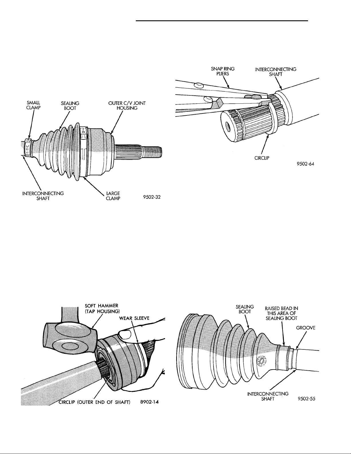
(2) Remove large boot clamp retaining C/V joint
sealing boot to C/V joint housing (Fig. 44) and discard. Remove small clamp that retains outer C/V
joint sealing boot to interconnecting shaft and discard. Remove sealing boot from outer C/V joint housing and slide it down interconnecting shaft.
Fig. 44 Outer C/V Joint Seal Boot Clamps
(3) Wipe away grease to expose outer C/V joint and
interconnecting shaft.
(4) Remove outer C/V joint from interconnecting
shaft using the following procedure: Support interconnecting shaft in a vise equipped with protec-
tive caps on jaws of vise to prevent damage to
interconnecting shaft. Then, using a soft–faced
hammer, sharply hit the end of the C/V joint hous-
ing to dislodge housing from internal circlip on interconnecting shaft (Fig. 45). Then slide outer C/V joint
off end of interconnecting shaft, joint may have to be
tapped off shaft using a soft–faced hammer.
(5) Remove large circlip (Fig. 46) from the interconnecting shaft before attempting to remove outer
C/V joint sealing boot.
Fig. 46 Circlip Removal from Interconnecting Shaft
(6) Slide failed sealing boot off interconnecting
shaft.
(7) Thoroughly clean and inspect outer C/V joint
assembly and interconnecting joint for any signs of
excessive wear. If any parts show signs of exces-
sive wear, the driveshaft assembly will require
replacement. Component parts of these driveshaft assemblies are not serviceable.
INSTALLATION
(1) Slide new sealing boot to interconnecting shaft
retaining clamp onto interconnecting shaft. Slide the
outer C/V joint assembly sealing boot onto the interconnecting shaft (Fig. 47). Seal boot MUST be
positioned on interconnecting shaft so the
raised bead on the inside of the seal boot is in
groove on interconnecting shaft.
Fig. 45 Outer C/V Joint Removal from
Interconnecting Shaft
Fig. 47 Sealing Boot Installation on Interconnecting
Shaft
Page 15
SOFT FACED HAMMERSTUB AXLEOUTER C/V JOINTNUT
INTERCONNECTINGSHAFTCROSSOUTER C/V JOINT ASSEM-BLY
SEALING
BOOT
CLAMP JAWS OF SPECIAL TOOLC-4975A MUST BECLOSED COMPLETELYTOGETHER HEREINTERCONNECTINGSHAFT
SPECIALTOOL C-4975AINTERCON-NECTING SHAFTCLAMPSEALINGBOOT
PL DIFFERENTIAL AND DRIVELINE 3 - 15
DISASSEMBLY AND ASSEMBLY (Continued)
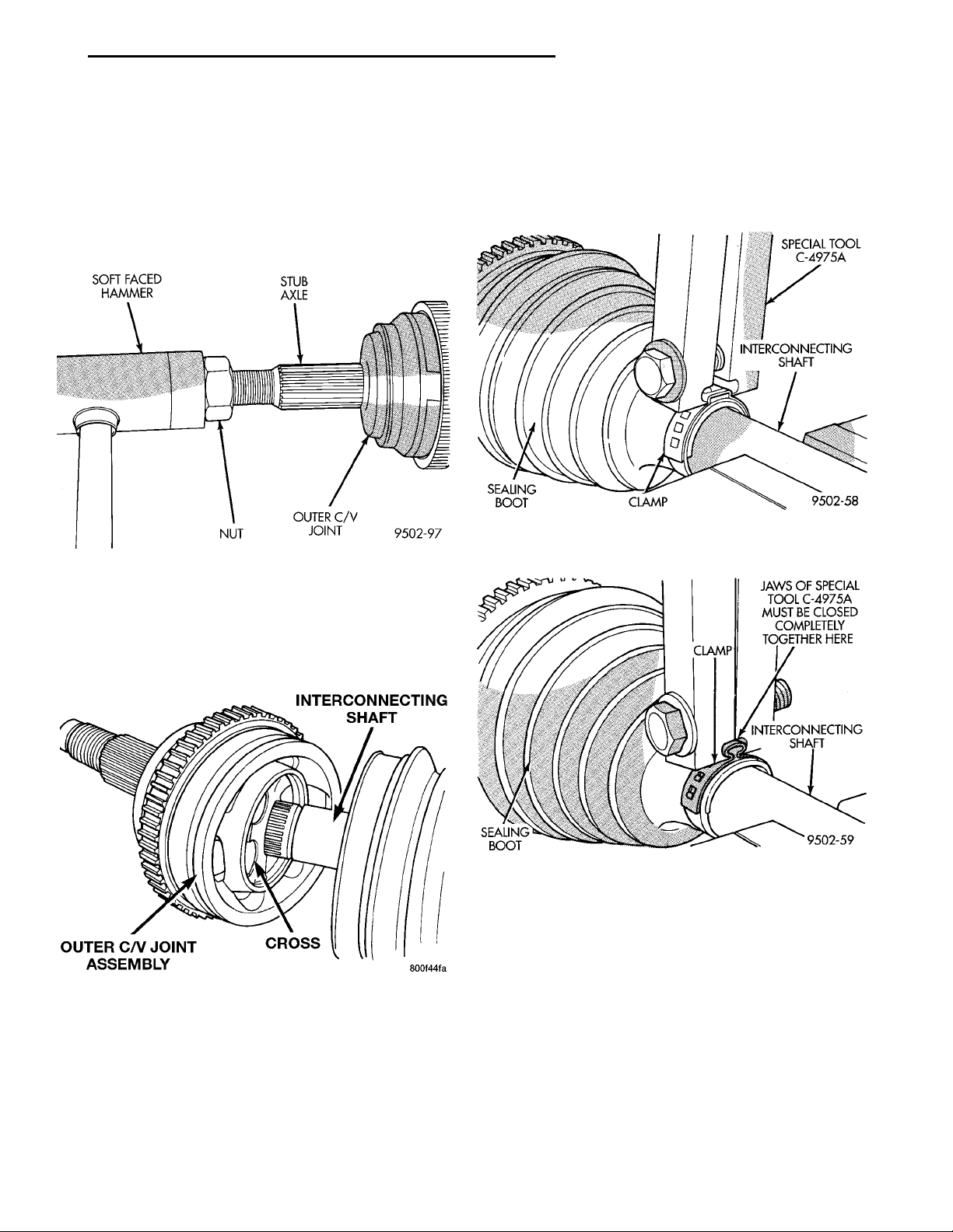
(2) Align splines on interconnecting shaft with
splines on cross of outer C/V joint assembly and start
outer C/V joint onto interconnecting shaft.
(3) Install outer C/V joint assembly onto interconnecting shaft by using a soft–faced hammer and
tapping end of stub axle (with nut installed) until
outer C/V joint is fully seated on interconnecting
shaft (Fig. 48).
Fig. 48 Outer C/V Joint Installation on
Interconnecting Shaft
(4) Outer C/V joint assembly must be installed on
interconnecting shaft until cross of outer C/V joint
assembly is seated against circlip on interconnecting
shaft (Fig. 49).
(7) Clamp sealing boot onto interconnecting shaft
using crimper, Special Tool C-4975-A and the following procedure. Place crimping tool C- 4975-A over
bridge of clamp (Fig. 50). Tighten nut on crimping
tool C- 4975-A until jaws on tool are closed completely together, face to face (Fig. 51).
Fig. 50 Crimping Tool Installed on Sealing Boot
Clamp
Fig. 49 Outer C/V Joint Correctly Installed on
Interconnecting Shaft
(5) Distribute 1/2 the amount of grease provided in
seal boot service package (DO NOT USE ANY
OTHER TYPE OF GREASE) into outer C/V joint
assembly housing. Put the remaining amount into
the sealing boot.
(6) Install outer C/V joint sealing boot to interconnecting shaft clamp evenly on sealing boot.
Fig. 51 Sealing Boot Retaining Clamp Installed
CAUTION: Seal must not be dimpled, stretched, or
out–of–shape in any way. If seal is NOT shaped correctly, equalize pressure in seal and shape it by
hand.
(8) Position outer C/V joint sealing boot into its
retaining groove on outer C/V joint housing. Install
sealing boot to outer C/V joint retaining clamp evenly
on sealing boot.
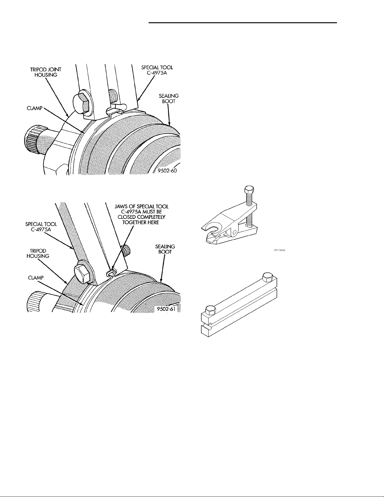
(9) Clamp sealing boot onto outer C/V joint housing using Crimper, Special Tool C-4975-A and the following procedure. Place crimping tool C- 4975-A over
bridge of clamp (Fig. 52). Tighten nut on crimping
Page 16
JAWS OF SPECIAL TOOLC-4975A MUST BE CLOSEDCOMPLETELY TOGETHERHERESEALING BOOTCLAMPTRIPOD HOUS-INGSPECIALTOOL C-4975A
TRIPOD JOINTHOUSINGSPECIALTOOLC-4975ASEALING BOOTCLAMP
3 - 16 DIFFERENTIAL AND DRIVELINE PL
DISASSEMBLY AND ASSEMBLY (Continued)
tool C- 4975-A until jaws on tool are closed completely together, face to face (Fig. 53).
Fig. 52 Crimping Tool Installed on Sealing Boot
Clamp
this section for the required driveshaft installation
procedure.
SPECIFICATIONS
TORQUE
DESCRIPTION TORQUE
Caliper To Knuckle Bolt .......31N·m(23ft.lbs.)
Driveshaft Nut ............183N·m(135 ft. lbs.)
Front Wheel Lug Nuts ......135N·m(100 ft. lbs.)
Knuckle To Ball Joint Bolt .....95N·m(70ft.lbs.)
Tie Rod End To Knuckle .......61N·m(45ft.lbs.)
SPECIAL TOOLS
DRIVESHAFT
Fig. 53 Sealing Boot Retaining Clamp Installed
(10) Install the driveshaft requiring boot replace-
ment back on the vehicle. See Servicing Driveshaft in
Tie Rod Remover MB-990635
Boot Clamp Installer C-4975A
 Loading...