

Page 1

PL EMISSION CONTROL SYSTEMS 25 - 1
EMISSION CONTROL SYSTEMS
CONTENTS
page page
EVAPORATIVE EMISSION CONTROLS ....... 12
EXHAUST GAS RECIRCULATION (EGR)
SYSTEM ............................ 19
ON-BOARD DIAGNOSTICS
INDEX
page page
GENERAL INFORMATION
SYSTEM DESCRIPTION .................. 1
DESCRIPTION AND OPERATION
CIRCUIT ACTUATION TEST MODE .......... 2
COMPONENT MONITORS ................ 10
DIAGNOSTIC TROUBLE CODES ............ 2
HIGH AND LOW LIMITS .................. 11
GENERAL INFORMATION
SYSTEM DESCRIPTION
The Powertrain Control Module (PCM) monitors
many different circuits in the fuel injection, ignition,
emission and engine systems. If the PCM senses a
problem with a monitored circuit often enough to
indicate an actual problem, it stores a Diagnostic
Trouble Code (DTC) in the PCM’s memory. If the
code applies to a non-emissions related component or
system, and the problem is repaired or ceases to
exist, the PCM cancels the code after 40 warmup
cycles. Diagnostic trouble codes that affect vehicle
emissions illuminate the Malfunction Indicator Lamp
(MIL). Refer to Malfunction Indicator Lamp in this
section.
Certain criteria must be met before the PCM
stores a DTC in memory. The criteria may be a specific range of engine RPM, engine temperature,
and/or input voltage to the PCM.
The PCM might not store a DTC for a monitored
circuit even though a malfunction has occurred. This
may happen because one of the DTC criteria for the
circuit has not been met. For example , assume the
diagnostic trouble code criteria requires the PCM to
monitor the circuit only when the engine operates
between 750 and 2000 RPM. Suppose the sensor’s
ON-BOARD DIAGNOSTICS ................. 1
LOAD VALUE .......................... 11
MALFUNCTION INDICATOR LAMP (MIL) ...... 1
MONITORED SYSTEMS .................. 7
NON-MONITORED CIRCUITS ............. 10
STATE DISPLAY TEST MODE .............. 2
TRIP DEFINITION ...................... 10
output circuit shorts to ground when engine operates
above 2400 RPM (resulting in 0 volt input to the
PCM). Because the condition happens at an engine
speed above the maximum threshold (2000 rpm), the
PCM will not store a DTC.
There are several operating conditions for which
the PCM monitors and sets DTC’s. Refer to Monitored Systems, Components, and Non-Monitored Circuits in this section.
NOTE: Various diagnostic procedures may actually
cause a diagnostic monitor to set a DTC. For
instance, pulling a spark plug wire to perform a
spark test may set the misfire code. When a repair
is completed and verified, use the DRB scan tool to
erase all DTC’s and extinguish the MIL.
Technicians can display stored DTC’s by two different methods. Refer to Diagnostic Trouble Codes in
this section. For DTC information, refer to charts in
this section.
DESCRIPTION AND OPERATION
MALFUNCTION INDICATOR LAMP (MIL)
As a functional test, the Malfunction Indicator
Lamp (MIL) illuminates at key-on before engine
Page 2
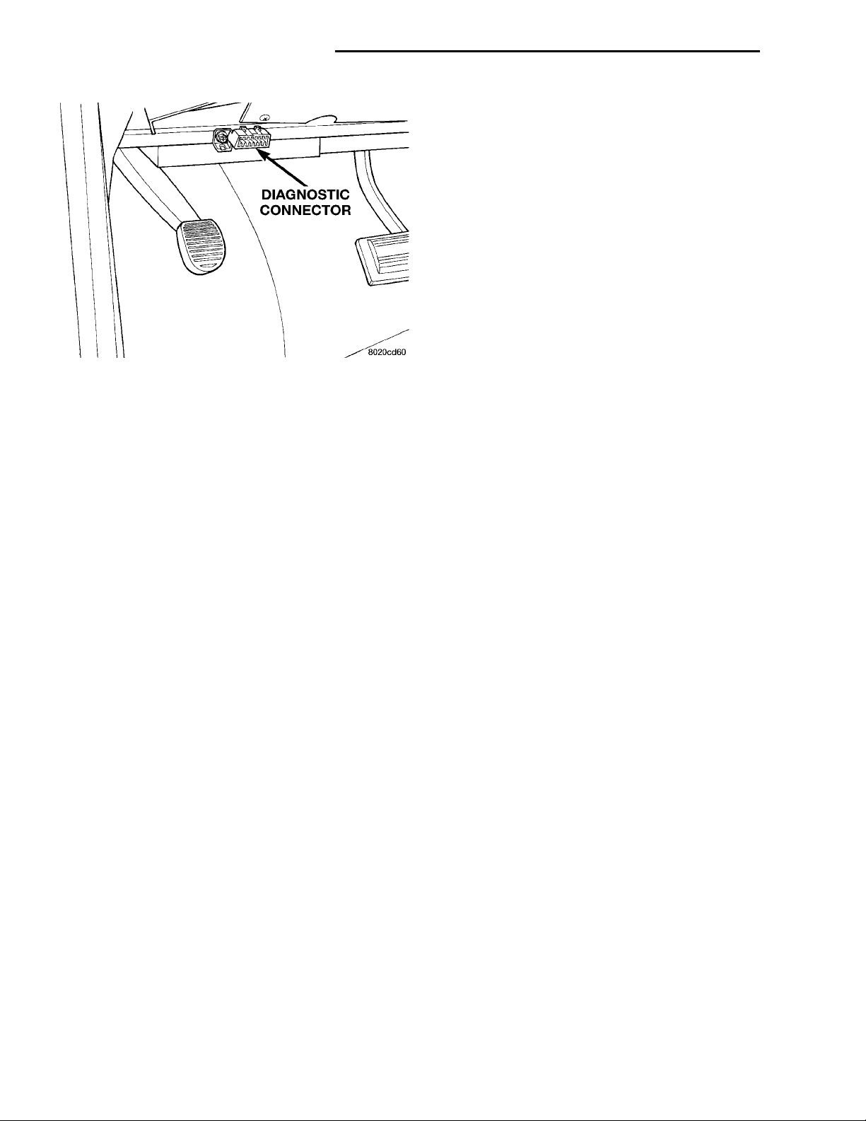
DIAGNOSTIC CON-NECTOR
25 - 2 EMISSION CONTROL SYSTEMS PL
DESCRIPTION AND OPERATION (Continued)
CIRCUIT ACTUATION TEST MODE
The Circuit Actuation Test Mode checks for proper
operation of output circuits or devices the Powertrain
Control Module (PCM) may not internally recognize.
The PCM attempts to activate these outputs and
allow an observer to verify proper operation. Most of
the tests provide an audible or visual indication of
device operation (click of relay contacts, fuel spray,
etc.). Except for intermittent conditions, if a device
functions properly during testing, assume the device,
its associated wiring, and driver circuit work correctly.
DIAGNOSTIC TROUBLE CODES
A Diagnostic Trouble Code (DTC) indicates the
PCM has recognized an abnormal condition in the
Fig. 1 Data Link (Diagnostic) Connector
cranking. Whenever the Powertrain Control Module
(PCM) sets a Diagnostic Trouble Code (DTC) that
affects vehicle emissions, it illuminates the MIL. If a
problem is detected, the PCM sends a message over
the CCD Bus to the instrument cluster to illuminate
the lamp. The PCM illuminates the MIL only for
DTC’s that affect vehicle emissions. The MIL stays
on continuously when the PCM has entered a
Limp-In mode or identified a failed emission component or system. The MIL remains on until the DTC
is erased. Refer to the Diagnostic Trouble Code
charts in this group for emission related codes.
Also, the MIL either flashes or illuminates continuously when the PCM detects active engine misfire.
Refer to Misfire Monitoring in this section.
Additionally, the PCM may reset (turn off) the MIL
when one of the following occur:
• PCM does not detect the malfunction for 3 consecutive trips (except misfire and fuel system monitors).
• PCM does not detect a malfunction while performing three successive engine misfire or fuel system tests. The PCM performs these tests while the
engine is operating within 6 375 RPM of and within
10 % of the load of the operating condition at which
the malfunction was first detected.
system.
The technician can retrieve and display DTC’s in
two different ways:
• The preferred and most accurate method of
retrieving a DTC is by using the DRB scan tool. The
scan tool supplies detailed diagnostic information
which can be used to more accurately diagnose
causes for a DTC.
• The second method is by observing the two-digit
number displayed at the Malfunction Indicator Lamp
(MIL). The MIL is displayed on the instrument panel
as the Check Engine lamp. This method is to be used
as a “quick-test” only. Always use the DRB scan tool
for detailed information.
Remember that DTC’s are the results of a system or circuit failure, but do not directly identify the failed component or components.
NOTE: For a list of DTC’s, refer to the charts in this
section.
BULB CHECK
Each time the ignition key is turned to the ON
position, the malfunction indicator (check engine)
lamp on the instrument panel should illuminate for
approximately 2 seconds then go out. This is done for
a bulb check.
STATE DISPLAY TEST MODE
The switch inputs to the Powertrain Control Module (PCM) have two recognized states; HIGH and
LOW. For this reason, the PCM cannot recognize the
difference between a selected switch position versus
an open circuit, a short circuit, or a defective switch.
If the State Display screen shows the change from
HIGH to LOW or LOW to HIGH, assume the entire
switch circuit to the PCM functions properly. From
the state display screen, access either State Display
Inputs and Outputs or State Display Sensors.
OBTAINING DTC’S USING DRB SCAN TOOL
(1) Connect the DRB scan tool to the data link
(diagnostic) connector. This connector is located in
the passenger compartment; at the lower edge of
instrument panel; near the steering column.
(2) Turn the ignition switch on and access the
“Read Fault” screen.
(3) Record all the DTC’s and “freeze frame” information shown on the DRB scan tool.
(4) To erase DTC’s, use the “Erase Trouble Code”
data screen on the DRB scan tool. Do not erase any
Page 3
PL EMISSION CONTROL SYSTEMS 25 - 3
DESCRIPTION AND OPERATION (Continued)
DTC’s until problems have been investigated
and repairs have been performed.
OBTAINING DTC’S USING MIL LAMP
(1) Cycle the ignition key On - Off - On - Off - On
within 5 seconds.
(2) Count the number of times the MIL (check
engine lamp) on the instrument panel flashes on and
off. The number of flashes represents the trouble
code. There is a slight pause between the flashes representing the first and second digits of the code.
Longer pauses separate individual two digit trouble
codes.
An example of a flashed DTC is as follows:
• Lamp flashes 4 times, pauses, and then flashes
6 more times. This indicates a DTC code number 46.
• Lamp flashes 5 times, pauses, and flashes 5
more times. This indicates a DTC code number 55. A
DTC 55 will always be the last code to be displayed.
This indicates the end of all stored codes.
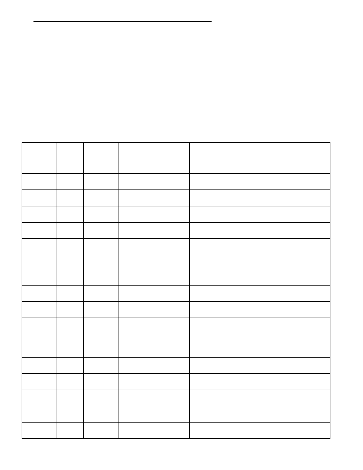
DIAGNOSTIC TROUBLE CODE DESCRIPTIONS
GENERIC
HEX
CODE
01 54** P0340 No Cam Signal at PCM No camshaft signal detected during engine
02 53** P0601 Internal Controller
05 47*** Charging System
06 46*** Charging System
0A 42* Auto Shutdown Relay
0B 41*** Generator Field Not
0C 37** P0743 Torque Converter
0E 35** P1491 Rad Fan Control Relay
0F 34* Speed Control Solenoid
10 33* A/C Clutch Relay
11 32** P0403 EGR Solenoid Circuit An open or shorted condition detected in the EGR
12 31** P0443 EVAP Purge Solenoid
13 27** P0203 Injector #3 Control
MIL
CODE
12* Battery Disconnect Direct battery input to PCM was disconnected
55* Completion of fault code display on Check Engine
SCAN
TOOL
CODE
DRB SCAN TOOL
DISPLAY
Failure
Voltage Too Low
Voltage Too High
Control Circuit
Switching Properly
Clutch Soleniod/Trans
Relay Circuits
Circuit
Circuits
Circuit
Circuit
Circuit
DESCRIPTION OF DIAGNOSTIC TROUBLE
CODE
within the last 50 Key-on cycles.
lamp.
cranking.
PCM Internal fault condition detected.
Battery voltage sense input below target charging
during engine operation. Also, no significant
change detected in battery voltage during active
test of generator output circuit.
Battery voltage sense input above target charging
voltage during engine operation.
An open or shorted condition detected in the auto
shutdown relay circuit.
An open or shorted condition detected in the
generator field control circuit.
An open or shorted condition detected in the
torque converter part throttle unlock solenoid
control circuit (3 speed auto RH trans. only).
An open or shorted condition detected in the low
speed radiator fan relay control circuit.
An open or shorted condition detected in the
Speed Control vacuum or vent solenoid circuits.
An open or shorted condition detected in the A/C
clutch relay circuit.
transducer solenoid circuit.
An open or shorted condition detected in the duty
cycle purge solenoid circuit.
Injector #3 output driver does not respond properly
to the control signal.
Page 4

25 - 4 EMISSION CONTROL SYSTEMS PL
DESCRIPTION AND OPERATION (Continued)
GENERIC
HEX
CODE
14 P0202 Injector #2 Control
15 P0201 Injector #1 Control
19 25** P0505 Idle Air Control Motor
1A 24** P0122 Throttle Position
1B P0123 Throttle Position
1E 22** P0117 ECT Sensor Voltage
1F P0118 ECT Sensor Voltage
20 21** P0134 Right Rear (or just)
21 17* Engine Is Cold Too
23 15** P0500 No Vehicle Speed
24 14** P0107 MAP Sensor Voltage
25 P0108 MAP Sensor Voltage
27 13** P1297 No Change in MAP
28 11* No Crank Reference
2A P0352 Ignition Coil #2 Primary
2B P0351 Ignition Coil #1 Primary
2C 42* No ASD Relay Output
2E 32** P0401 EGR System Failure Required change in air/fuel ratio not detected
MIL
CODE
SCAN
TOOL
CODE
or
or
or
or
or
or
DRB SCAN TOOL
DISPLAY
Circuit
Circuit
Circuits
Sensor Voltage Low
Sensor Voltage High
Too Low
Too High
Upstream O2S Stays at
Center
Long
Sensor Signal
Too Low
Too High
From Start to Run
Signal at PCM
Circuit
Circuit
Voltage at PCM
DESCRIPTION OF DIAGNOSTIC TROUBLE
CODE
Injector #2 output driver does not respond properly
to the control signal.
Injector #1 output driver does not respond properly
to the control signal.
A shorted or open condition detected in one or
more of the idle air control motor circuits.
Throttle position sensor input below the minimum
acceptable voltage.
Throttle position sensor input above the maximum
acceptable voltage.
Engine coolant temperature sensor input below
minimum acceptable voltage.
Engine coolant temperature sensor input above
maximum acceptable voltage.
Neither rich or lean condition detected from the
oxygen sensor.
Engine did not reach operating temperature within
acceptable limits.
No vehicle speed sensor signal detected during
road load conditions.
MAP sensor input below minimum acceptable
voltage.
MAP sensor input above maximum acceptable
voltage.
No difference recognized between the engine MAP
reading and the barometric (atmospheric) pressure
reading from start-up.
No crank reference signal detected during engine
cranking.
Peak primary circuit current not achieved with
maximum dwell time.
Peak primary circuit current not achieved with
maximum dwell time.
An Open condition Detected In The ASD Relay
Output Circuit.
during diagnostic test.
Page 5

PL EMISSION CONTROL SYSTEMS 25 - 5
DESCRIPTION AND OPERATION (Continued)
GENERIC
HEX
CODE
30 62* P1697 PCM Failure SRI Miles
31 63** P1696 PCM Failure EEPROM
39 23** P0112 Intake Air Temp Sensor
3A P0113 Intake Air Temp Sensor
3C 61 P0106 Baro Out of Range
3D 27** P0204 Injector #4 Control
3E 21** P0132 Right Rear (or just)
44 53** P0600 PCM Failure SPI
52 77 S/C Power Relay Ckt
65 42* Fuel Pump Relay
66 21** P0133 Right Bank Upstream
67 P0135 Right Rear (or just)
69 P0141 Right Rear (or just)
6A 43** P0300 Multiple Cylinder
6B P0301 Cylinder #1 Mis-fire Misfire detected in cylinder #1.
6C P0302 Cylinder #2 Mis-fire Misfire detected in cylinder #2.
6D P0303 Cylinder #3 Mis-fire Misfire detected in cylinder #3.
6E P0304 Cylinder #4 Mis-fire Misfire detected in cylinder #4.
70 72** P0420 Right Rear (or just)
71 31 P0441 Incurrect Pruge Flow
MIL
CODE
SCAN
TOOL
CODE
or
or
or
or
or
or
or
DRB SCAN TOOL
DISPLAY
Not Stored
Write Denied
Voltage Low
Voltage High
Circuit
Upstream O2S Shorted
to Voltage
Communications
Control Circuit
O2S Slow Response
Upstream O2S Heater
Failure
Downstream O2S
Heater Failure
Mis-fire
Catalyst Efficency
Failure
DESCRIPTION OF DIAGNOSTIC TROUBLE
CODE
Unsuccessful attempt to update EMR mileage in
the PCM EEPROM
Unsuccessful attempt to write to an EEPROM
location by the PCM.
Intake air temperature sensor input below the
maximum acceptable voltage.
Intake air temperature sensor input above the
minimum acceptable voltage.
Injector #4 output driver does not respond properly
to the control signal.
Oxygen sensor input voltage maintained above the
normal operating range.
PCM Internal fault condition detected.
An open or shorted condition detected in the fuel
pump relay control circuit.
Oxygen sensor response slower than minimum
required switching frequency.
Upstream oxygen sensor heating element circuit
malfunction.
Oxygen sensor heating element circuit
malfunction.
Misfire detected in multiple cylinders.
Catalyst efficiency below required level.
Page 6
25 - 6 EMISSION CONTROL SYSTEMS PL
DESCRIPTION AND OPERATION (Continued)
GENERIC
HEX
CODE
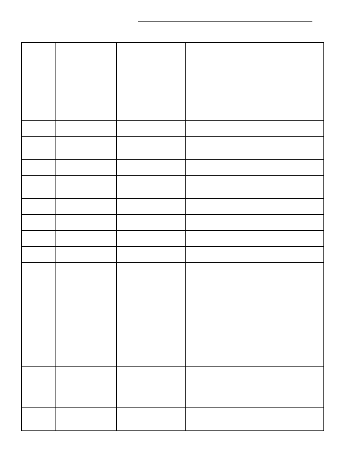
72 37** P1899 P/N Switch Stuck in
73 65* P0551 Power Steering Switch
76 52** P0172 Right Rear (or just)
77 51** P0171 Right Rear (or just)
7E 21** P0138 Right Rear (or just)
80 17** P0125 Closed Loop Temp Not
81 21** P0140 Right Rear (or just)
84 24** P0121 TPS Voltage Does Not
8A 25** P1294 Target Idle Not
91 25** P1299 Vacuum Leak Found
92 71** P1496 5 Volt Supply Output
94 37* P0740 Torq Conv Clu, No
95 42* Fuel Level Sending
96 Fuel Level Sending
97 Fuel Level Unit No
98 65** P0703 Brake Switch Stuck
99 44** P1493 Ambient/Batt Temp Sen
9A P1492 Ambient/Batt Temp
9B 21** P0131 Right Rear (or just)
MIL
CODE
SCAN
TOOL
CODE
or
or
or
DRB SCAN TOOL
DISPLAY
Park or in Gear
Failure
Fuel System Rich
Fuel System Lean
Downstream O2S
Shorted to Voltage
Reached
Downstream O2S
Stays at Center
Agree With MAP
Reached
(IAC Fully Seated)
Too Low
RPM Drop At Lockup
Unit Volts Too Low
Unit Volts Too High
Change Over Miles
Pressed or Released
VoltsToo Low
Sensor VoltsToo High
Upstream O2S Shorted
to Ground
DESCRIPTION OF DIAGNOSTIC TROUBLE
CODE
Incorrect input state detected for the Park/Neutral
switch, auto. trans. only.
Power steering high pressure seen at high speed
(2.5L only).
A rich air/fuel mixture has been indicated by an
abnormally lean correction factor.
A lean air/fuel mixture has been indicated by an
abnormally rich correction factor.
Oxygen sensor input voltage maintained above the
normal operating range.
Engine does not reach 20°F within 5 minutes with
a vehicle speed signal.
Neither reich or lean condition detected from the
downstream oxygen sensor.
TPS signal does not correlate to MAP sensor.
Actual idle speed does not equal target idle speed.
MAP sensor signal does not correlate to throttle
position sensor signal. Possible vacuum leak.
5 volt output from regulator does not meet
minimum requirement.
Relationship between engine speed and vehicle
speed indicates no torque converter clutch
engagement (auto. trans. only).
Open circuit between PCM and fuel gauge
sending unit.
Circuit shorted to voltage between PCM and fuel
gauge sending unit.
No movement of fuel level sender detected.
No release of brake switch seen after too many
accelerations.
Battery temperature sensor input voltage below an
acceptable range.
Battery temperature sensor input voltage above an
acceptable range.
O2 sensor voltage too low, tested after cold start.
Page 7

PL EMISSION CONTROL SYSTEMS 25 - 7
DESCRIPTION AND OPERATION (Continued)
GENERIC
HEX
CODE
9C P0137 Right Rear (or just)
9D 11** P1391 Intermittent Loss of
AO 31** PO442 Evap Leak Monitor
A1 PO455 Evap Leak Monitor
B7 31** P1495 Leak DetectionPump
B8 P1494 Leak detect Pump Sw
BA 11** P1398 Mis-fire Adaptive
BB 31 P1486 Evap Hose Pinched A pinched or bent Evap hose.
CO 21 PO133 Cat Mon Slow O2
MIL
CODE
SCAN
TOOL
CODE
or
or
or
DRB SCAN TOOL
DISPLAY
Downstream O2S
Shorted to Ground
CMP or CKP
Small Leak detected
Large Leak Detected
Soleniod Circuit
or Mechanical Fault
Numerator at Limit
Upstream
DESCRIPTION OF DIAGNOSTIC TROUBLE
CODE
O2 sensor voltage too low, tested after cold start.
Intermittent loss of either camshaft or crankshaft
position sensor.
A small leak has been detected by the leak
detection monitor.
The leak detection monitor is unable to pressurize
Evap system, indicating a large leak.
Leak detection pump soleniod circuit fault (open or
Short).
Leak detection pump switch does not respond to
input.
CKP sensor target windows have too much
variation.
Oxygen sensor response slower than minimum
required switching frequency.
* Check Engine Lamp (MIL) will not illuminate if this Diagnostic Trouble Code was recorded. Cycle Ignition
key as described in manual and observe code flashed by Check Engine lamp.
** Check Engine Lamp (MIL) will illuminate during engine operation if this Diagnostic Trouble Code was
recorded.
*** Generator Lamp illuminated
MONITORED SYSTEMS
There are new electronic circuit monitors that
check fuel, emission, engine and ignition performance. These monitors use information from various
sensor circuits to indicate the overall operation of the
fuel, engine, ignition and emission systems and thus
the emissions performance of the vehicle.
The fuel, engine, ignition and emission systems
monitors do not indicate a specific component problem. They do indicate that there is an implied problem within one of the systems and that a specific
problem must be diagnosed.
If any of these monitors detect a problem affecting
vehicle emissions, the Malfunction Indicator (Check
Engine) Lamp will be illuminated. These monitors
generate Diagnostic Trouble Codes that can be displayed with the check engine lamp or a scan tool.
The following is a list of the system monitors:
• EGR Monitor
• Misfire Monitor
• Fuel System Monitor
• Oxygen Sensor Monitor
• Oxygen Sensor Heater Monitor
• Catalyst Monitor
• Evaporative System Leak Detection Monitor
Following is a description of each system monitor,
and its DTC.
Refer to the appropriate Powertrain Diagnostics Procedures manual for diagnostic procedures.
DTC 21—HEX 66, and 7A—OXYGEN SENSOR (O2S) MONITOR
Effective control of exhaust emissions is achieved
by an oxygen feedback system. The most important
element of the feedback system is the O2S. The O2S
is located in the exhaust path. Once it reaches operating temperature 300° to 350°C (572° to 662°F), the
sensor generates a voltage that is inversely proportional to the amount of oxygen in the exhaust. The
information obtained by the sensor is used to calcu-
Page 8

25 - 8 EMISSION CONTROL SYSTEMS PL
DESCRIPTION AND OPERATION (Continued)
late the fuel injector pulse width. This maintains a
14.7 to 1 air fuel (A/F) ratio. At this mixture ratio,
the catalyst works best to remove hydrocarbons (HC),
carbon monoxide (CO) and nitrous oxide (NOx) from
the exhaust.
The O2S is also the main sensing element for the
EGR, Catalyst and Fuel Monitors.
The O2S may fail in any or all of the following
manners:
• Slow response rate
• Reduced output voltage
• Dynamic shift
• Shorted or open circuits
Response rate is the time required for the sensor to
switch from lean to rich once it is exposed to a richer
than optimum A/F mixture or vice versa. As the sensor starts malfunctioning, it could take longer to
detect the changes in the oxygen content of the
exhaust gas.
The output voltage of the O2S ranges from 0 to 1
volt. A good sensor can easily generate any output
voltage in this range as it is exposed to different concentrations of oxygen. To detect a shift in the A/F
mixture (lean or rich), the output voltage has to
change beyond a threshold value. A malfunctioning
sensor could have difficulty changing beyond the
threshold value.
DTC 21—HEX 67, 69, 7C, and 7D—OXYGEN SENSOR HEATER MONITOR
If there is an oxygen sensor (O2S) DTC as well as
a O2S heater DTC, the O2S fault MUST be repaired
first. After the O2S fault is repaired, verify that the
heater circuit is operating correctly.
Effective control of exhaust emissions is achieved
by an oxygen feedback system. The most important
element of the feedback system is the O2S. The O2S
is located in the exhaust path. Once it reaches operating temperature 300° to 350°C (572 °to 662°F), the
sensor generates a voltage that is inversely proportional to the amount of oxygen in the exhaust. The
information obtained by the sensor is used to calculate the fuel injector pulse width. This maintains
a14.7 to 1 Air Fuel (A/F) ratio. At this mixture ratio,
the catalyst works best to remove hydrocarbons (HC),
carbon monoxide (CO) and nitrogen oxide (NOx) from
the exhaust.
The voltage readings taken from the O2S are very
temperature sensitive. The readings are not accurate
below 300°C. Heating of the O2S is done to allow the
engine controller to shift to closed loop control as
soon as possible. The heating element used to heat
the O2S must be tested to ensure that it is heating
the sensor properly.
The O2S circuit is monitored for a drop in voltage.
The sensor output is used to test the heater by iso-
lating the effect of the heater element on the O2S
output voltage from the other effects.
DTC 32—HEX 2E—EGR MONITOR
The Powertrain Control Module (PCM) performs
an on-board diagnostic check of the EGR system.
The EGR system consists of two main components:
a vacuum solenoid and a vacuum operated valve with
a back pressure transducer. The EGR monitor is used
to test whether the EGR system is operating within
specifications. The diagnostic check activates only
during selected engine/driving conditions. When the
conditions are met, the EGR is turned off (solenoid
energized) and the O2S compensation control is monitored. Turning off the EGR shifts the air fuel (A/F)
ratio in the lean direction. The O2S data should indicate an increase in the O2 concentration in the combustion chamber when the exhaust gases are no
longer recirculated. While this test does not directly
measure the operation of the EGR system, it can be
inferred from the shift in the O2S data whether the
EGR system is operating correctly. Because the O2S
is being used, the O2S test must pass its test before
the EGR test.
DTC 43—HEX 6A,6B, 6C, 6D, 6E, AE, and AF—MISFIRE MONITOR
Excessive engine misfire results in increased catalyst temperature and causes an increase in HC emissions. Severe misfires could cause catalyst damage.
To prevent catalytic convertor damage, the PCM
monitors engine misfire.
The Powertrain Control Module (PCM) monitors
for misfire during most engine operating conditions
(positive torque) by looking at changes in the crankshaft speed. If a misfire occurs the speed of the
crankshaft will vary more than normal.
DTC 51/52—HEX 76, 77, 78, and 79—FUEL SYSTEM MONITOR
To comply with clean air regulations, vehicles are
equipped with catalytic converters. These converters
reduce the emission of hydrocarbons, oxides of nitrogen and carbon monoxide. The catalyst works best
when the air fuel (A/F) ratio is at or near the optimum of 14.7 to 1.
The PCM is programmed to maintain the optimum
air/fuel ratio of 14.7 to 1. This is done by making
short term corrections in the fuel injector pulse width
based on the O2S output. The programmed memory
acts as a self calibration tool that the engine controller uses to compensate for variations in engine specifications, sensor tolerances and engine fatigue over
the life span of the engine. By monitoring the actual
air-fuel ratio with the O2S (short term) and multiplying that with the program long-term (adaptive) memory and comparing that to the limit, it can be
Page 9

PL EMISSION CONTROL SYSTEMS 25 - 9
DESCRIPTION AND OPERATION (Continued)
determined whether it will pass an emissions test. If
a malfunction occurs such that the PCM cannot
maintain the optimum A/F ratio, then the MIL will
be illuminated.
DTC 64—HEX 70, and B4—CATALYST
MONITOR
To comply with clean air regulations, vehicles are
equipped with catalytic converters. These converters
reduce the emission of hydrocarbons, oxides of nitrogen and carbon monoxide.
Normal vehicle miles or engine misfire can cause a
catalyst to decay. A meltdown of the ceramic core can
cause a reduction of the exhaust passage. This can
increase vehicle emissions and deteriorate engine
performance, driveability and fuel economy.
The catalyst monitor uses dual oxygen sensors
(O2S’s) to monitor the efficiency of the converter. The
dual O2Ss strategy is based on the fact that as a catalyst deteriorates, its oxygen storage capacity and its
efficiency are both reduced. By monitoring the oxygen storage capacity of a catalyst, its efficiency can
be indirectly calculated. The upstream O2S is used to
detect the amount of oxygen in the exhaust gas
before the gas enters the catalytic converter. The
PCM calculates the A/F mixture from the output of
the O2S. A low voltage indicates high oxygen content
(lean mixture). A high voltage indicates a low content
of oxygen (rich mixture).
When the upstream O2S detects a lean condition,
there is an abundance of oxygen in the exhaust gas.
A functioning converter would store this oxygen so it
can use it for the oxidation of HC and CO. As the
converter absorbs the oxygen, there will be a lack of
oxygen downstream of the converter. The output of
the downstraem O2S will indicate limited activity in
this condition.
As the converter loses the ability to store oxygen,
the condition can be detected from the behavior of
the downstream O2S. When the efficiency drops, no
chemical reaction takes place. This means the concentration of oxygen will be the same downstream as
upstream. The output voltage of the downstream
O2S copies the voltage of the upstream sensor. The
only difference is a time lag (seen by the PCM)
between the switching of the O2S’s.
To monitor the system, the number of lean-to-rich
switches of upstream and downstream O2S’s is
counted. The ratio of downstream switches to
upstream switches is used to determine whether the
catalyst is operating properly. An effective catalyst
will have fewer downstream switches than it has
upstream switches i.e., a ratio closer to zero. For a
totally ineffective catalyst, this ratio will be one-toone, indicating that no oxidation occurs in the device.
The system must be monitored so that when catalyst efficiency deteriorates and exhaust emissions
increase to over the legal limit, the MIL (check
engine lamp) will be illuminated.
DTC 31—HEX A0, A1, B7, and B8—LEAK
DETECTION PUMP MONITOR
The leak detection assembly incorporates two primary functions: it must detect a leak in the evaporative system and seal the evaporative system so the
leak detection test can be run.
The primary components within the assembly are:
A three port solenoid that activates both of the functions listed above; a pump which contains a switch,
two check valves and a spring/diaphragm, a canister
vent valve (CVV) seal which contains a spring loaded
vent seal valve.
Immediately after a cold start, between predetermined temperature thresholds limits, the three port
solenoid is briefly energized. This initializes the
pump by drawing air into the pump cavity and also
closes the vent seal. During non test conditions the
vent seal is held open by the pump diaphragm
assembly which pushes it open at the full travel position. The vent seal will remain closed while the
pump is cycling due to the reed switch triggering of
the three port solenoid that prevents the diaphragm
assembly from reaching full travel. After the brief
initialization period, the solenoid is de-energized
allowing atmospheric pressure to enter the pump
cavity, thus permitting the spring to drive the diaphragm which forces air out of the pump cavity and
into the vent system. When the solenoid is energized
and de energized, the cycle is repeated creating flow
in typical diaphragm pump fashion. The pump is controlled in 2 modes:
Pump Mode: The pump is cycled at a fixed rate to
achieve a rapid pressure build in order to shorten the
overall test length.
Test Mode: The solenoid is energized with a fixed
duration pulse. Subsequent fixed pulses occur when
the diaphragm reaches the Switch closure point.
The spring in the pump is set so that the system
will achieve an equalized pressure of about 7.5” H20.
The cycle rate of pump strokes is quite rapid as the
system begins to pump up to this pressure. As the
pressure increases, the cycle rate starts to drop off. If
there is no leak in the system, the pump would eventually stop pumping at the equalized pressure. If
there is a leak, it will continue to pump at a rate representative of the flow characteristic of the size of the
leak. From this information we can determine if the
leak is larger than the required detection limit (currently set at .040” orifice by CARB). If a leak is
revealed during the leak test portion of the test, the
test is terminated at the end of the test mode and no
further system checks will be performed.
After passing the leak detection phase of the test,
system pressure is maintained by turning on the
Page 10

25 - 10 EMISSION CONTROL SYSTEMS PL
DESCRIPTION AND OPERATION (Continued)
LDP’s solenoid until the purge system is activated.
Purge activation in effect creates a leak. The cycle
rate is again interrogated and when it increases due
to the flow through the purge system, the leak check
portion of the diagnostic is complete.
The canister vent valve will unseal the system
after completion of the test sequence as the pump
diaphragm assembly moves to the full travel position.
Evaporative system functionality will be verified by
using the stricter evap purge flow monitor. At an
appropriate warm idle the LDP will be energized to
seal the canister vent. The purge flow will be clocked
up from some small value in an attempt to see a
shift in the 02 control system. If fuel vapor, indicated
by a shift in the 02 control, is present the test is
passed. If not, it is assumed that the purge system is
not functioning in some respect. The LDP is again
turned off and the test is ended.
TRIP DEFINITION
A “Trip” means vehicle operation (following an
engine-off period) of duration and driving mode such
that all components and systems are monitored at
least once by the diagnostic system. The monitors
must successfully pass before the PCM can verify
that a previously malfunctioning component is meeting the normal operating conditions of that component. For misfire or fuel system malfunction, the
MIL may be extinguished if the fault does not recur
when monitored during three subsequent sequential
driving cycles in which conditions are similar to
those under which the malfunction was first determined.
Anytime the MIL is illuminated, a DTC is stored.
The DTC can self erase only when the MIL has been
extinguished. Once the MIL is extinguished, the
PCM must pass the diagnostic test for the most
recent DTC for 40 warm-up cycles (80 warm-up
cycles for the Fuel System Monitor and the Misfire
Monitor). A warm-up cycle can best be described by
the following:
• The engine must be running
• A rise of 40°F in engine temperature must occur
from the time when the engine was started
• Engine coolant temperature must reach at least
160°F
• A “driving cycle” that consists of engine start up
and engine shut off.
Once the above conditions occur, the PCM is considered to have passed a warm-up cycle. Due to the
conditions required to extinguish the MIL and erase
the DTC, it is most important that after a repair has
been made, all DTC’s be erased and the repair verified.
COMPONENT MONITORS
There are several components that will affect vehicle emissions if they malfunction. If one of these components malfunctions the Malfunction Indicator
Lamp (Check Engine) will illuminate.
Some of the component monitors are checking for
proper operation of the part. Electrically operated
components now have input (rationality) and output
(functionality) checks. Previously, a component like
the Throttle Position sensor (TPS) was checked by
the PCM for an open or shorted circuit. If one of
these conditions occurred, a DTC was set. Now there
is a check to ensure that the component is working.
This is done by watching for a TPS indication of a
greater or lesser throttle opening than MAP and
engine rpm indicate. In the case of the TPS, if engine
vacuum is high and engine rpm is 1600 or greater
and the TPS indicates a large throttle opening, a
DTC will be set. The same applies to low vacuum
and 1600 rpm.
Any component that has an associated limp in will
set a fault after 1 trip with the malfunction present.
Refer to the Diagnostic Trouble Codes Description
Charts in this section and the appropriate Powertrain Diagnostic Procedure Manual for diagnostic
procedures.
NON-MONITORED CIRCUITS
The PCM does not monitor all circuits, systems
and conditions that could have malfunctions causing
driveability problems. However, problems with these
systems may cause the PCM to store diagnostic trouble codes for other systems or components. For example, a fuel pressure problem will not register a fault
directly, but could cause a rich/lean condition or misfire. This could cause the PCM to store an oxygen
sensor or misfire diagnostic trouble code.
The major non-monitored circuits are listed below
along with examples of failures modes that do not
directly cause the PCM to set a DTC, but for a system that is monitored.
FUEL PRESSURE
The fuel pressure regulator controls fuel system
pressure. The PCM cannot detect a clogged fuel
pump inlet filter, clogged in-line fuel filter, or a
pinched fuel supply or return line. However, these
could result in a rich or lean condition causing the
PCM to store an oxygen sensor or fuel system diagnostic trouble code.
SECONDARY IGNITION CIRCUIT
The PCM cannot detect an inoperative ignition coil,
fouled or worn spark plugs, ignition cross firing, or
open spark plug cables.
Page 11

PL EMISSION CONTROL SYSTEMS 25 - 11
DESCRIPTION AND OPERATION (Continued)
CYLINDER COMPRESSION
The PCM cannot detect uneven, low, or high engine
cylinder compression.
EXHAUST SYSTEM
The PCM cannot detect a plugged, restricted or
leaking exhaust system. It may set a EGR or Fuel
system fault or O2S.
FUEL INJECTOR MECHANICAL
MALFUNCTIONS
The PCM cannot determine if a fuel injector is
clogged, the needle is sticking or if the wrong injector
is installed. However, these could result in a rich or
lean condition causing the PCM to store a diagnostic
trouble code for either misfire, an oxygen sensor, or
the fuel system.
EXCESSIVE OIL CONSUMPTION
Although the PCM monitors engine exhaust oxygen
content when the system is in closed loop, it cannot
determine excessive oil consumption.
THROTTLE BODY AIR FLOW
The PCM cannot detect a clogged or restricted air
cleaner inlet or filter element.
VACUUM ASSIST
The PCM cannot detect leaks or restrictions in the
vacuum circuits of vacuum assisted engine control
system devices. However, these could cause the PCM
to store a MAP sensor diagnostic trouble code and
cause a high idle condition.
PCM SYSTEM GROUND
The PCM cannot determine a poor system ground.
However, one or more diagnostic trouble codes may
be generated as a result of this condition. The module should be mounted to the body at all times, also
during diagnostic.
PCM CONNECTOR ENGAGEMENT
The PCM may not be able to determine spread or
damaged connector pins. However, it might store
diagnostic trouble codes as a result of spread connector pins.
HIGH AND LOW LIMITS
The PCM compares input signal voltages from each
input device with established high and low limits for
the device. If the input voltage is not within limits
and other criteria are met, the PCM stores a diagnostic trouble code in memory. Other diagnostic trouble
code criteria might include engine RPM limits or
input voltages from other sensors or switches that
must be present before verifying a diagnostic trouble
code condition.
LOAD VALUE
ENGINE IDLE/NEUTRAL 2500 RPM/NEUTRAL
2.0L SOHC 2% to 8% of Maximum Load 8% to 15% of Maximum Load
2.4L DOHC 2% to 8% of Maximum Load 7% to 15% of Maximum Load
2.5L SOHC 2% to 8% of Maximum Load 7% to 15% of Maximum Load
Page 12
REAR OFFRONT FASCIAEVAP CANIS-TER
25 - 12 EMISSION CONTROL SYSTEMS PL
EVAPORATIVE EMISSION CONTROLS
INDEX
page page
DESCRIPTION AND OPERATION
DUTY CYCLE EVAP PURGE SOLENOID
VALVE .............................. 12
EVAP CANISTER ....................... 12
EVAPORATION CONTROL SYSTEM ........ 12
LEAK DETECTION PUMP ................ 13
POSITIVE CRANKCASE VENTILATION (PCV)
SYSTEMS ........................... 14
PRESSURE RELIEF/ROLLOVER VALVE ..... 12
DESCRIPTION AND OPERATION
EVAPORATION CONTROL SYSTEM
The evaporation control system prevents the emission
of fuel tank vapors into the atmosphere. When fuel
evaporates in the fuel tank, the vapors pass through
vent hoses or tubes to a charcoal filled evaporative canister. The canister temporarily holds the vapors. The
Powertrain Control Module (PCM) allows intake manifold vacuum to draw vapors into the combustion chambers during certain operating conditions.
All engines use a duty cycle purge system. The
PCM controls vapor flow by operating the duty cycle
EVAP purge solenoid. Refer to Duty Cycle EVAP
Purge Solenoid in this section.
NOTE: The evaporative system uses specially manufactured hoses. If they need replacement, only use
fuel resistant hose.
PRESSURE-VACUUM FILLER CAP ......... 13
VEHICLE EMISSION CONTROL INFORMATION
LABEL .............................. 15
DIAGNOSIS AND TESTING
LEAK DETECTION PUMP ................ 15
PCV VALVE TEST ...................... 15
VACUUM SCHEMATIC ................... 15
REMOVAL AND INSTALLATION
LEAK DETECTION PUMP REPLACEMENT . . . 18
canister through the duty cycle EVAP purge solenoid.
The PCM purges the canister at predetermined intervals and engine conditions.
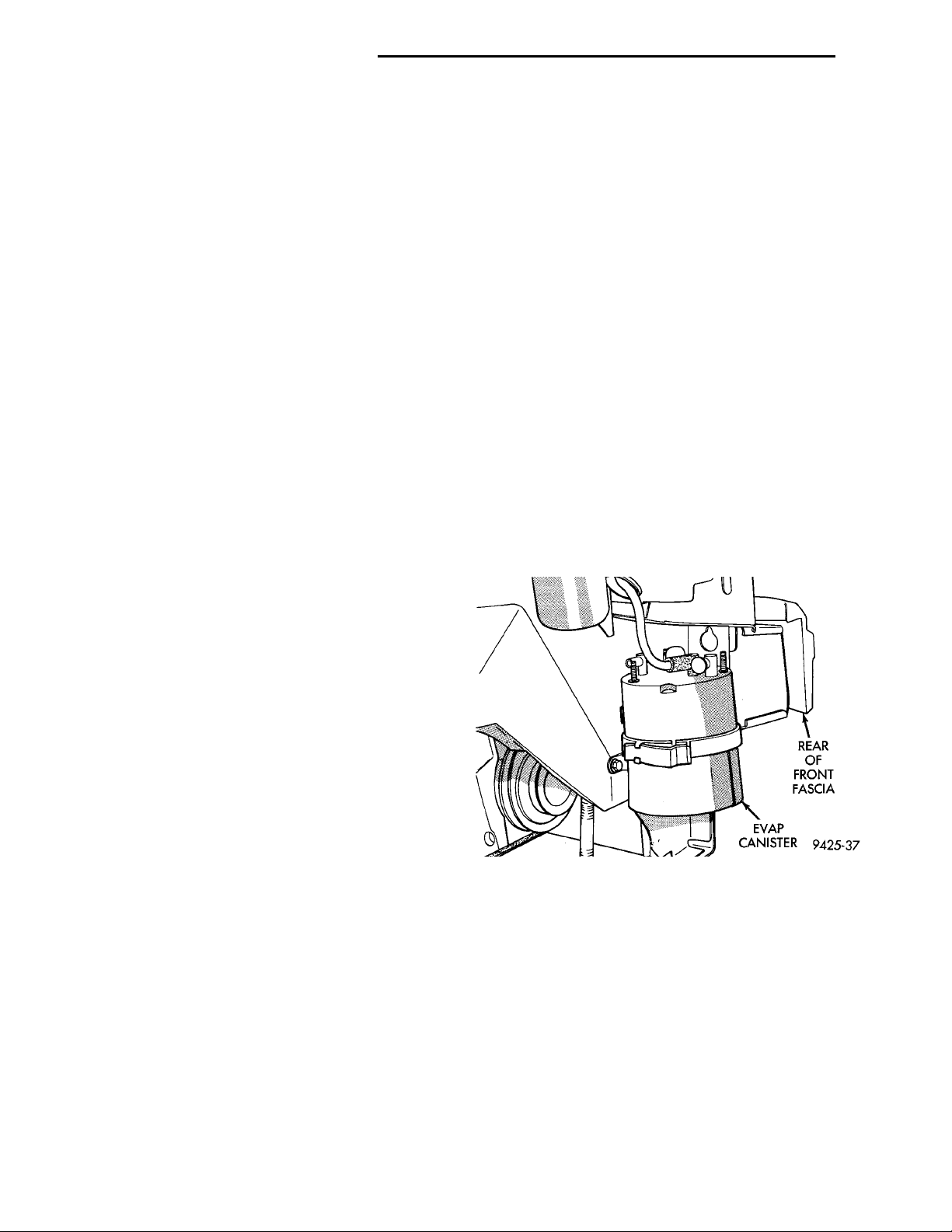
The canister mounts to a bracket behind the front
fascia on the passengers side of the vehicle (Fig. 1).
The vacuum and vapor tube connect to the top of the
canister.
PRESSURE RELIEF/ROLLOVER VALVE
All vehicles have a combination pressure relief and
rollover valve. The dual function valve relieves fuel
tank pressure. The valve also prevents fuel flow
through the fuel tank vent valve hoses should the
vehicle rollover. All vehicles pass a 360° rollover.
The pressure relief valve opens at a certain pressure.
When fuel tank pressure increases above the calibrated
pressure, the valve opens to release fuel tank vapors
pressure. The charcoal filled evaporative canister stores
the vapors. For pressure relief/rollover valve service,
refer to the Fuel Tank section of Group 14.
EVAP CANISTER
All vehicles use a sealed, maintenance free, evaporative (EVAP) canister. Fuel tank pressure vents into
the canister. The canister temporarily holds the fuel
vapors until intake manifold vacuum draws them
into the combustion chamber. The PCM purges the
Fig. 1 EVAP Canister
DUTY CYCLE EVAP PURGE SOLENOID VALVE
The duty cycle EVAP purge solenoid regulates the
rate of vapor flow from the EVAP canister to the
throttle body. The PCM operates the solenoid.
During the cold start warm-up period and the hot
start time delay, the PCM does not energize the solenoid. When de-energized, no vapors are purged.
When purging, the PCM energizes and de-energizes the solenoid approximately 5 or 10 times per
second, depending upon operating conditions. The
PCM varies the vapor flow rate by changing solenoid
pulse width. Pulse width is the amount of time the
solenoid energizes.
Page 13
PLASTICTETHERGASKETCUT-AWAY
PL EMISSION CONTROL SYSTEMS 25 - 13
DESCRIPTION AND OPERATION (Continued)
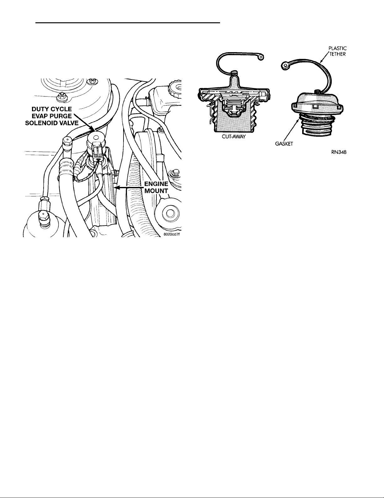
The solenoid attaches to a bracket which is
attached to the front engine mount (Fig. 2). The solenoid will not operate properly unless it is installed
with the electrical connector at the top.
Fig. 3 Pressure Vacuum Filler Cap
pump by drawing air into the pump cavity and also
closes the vent seal. During non-test test conditions,
the vent seal is held open by the pump diaphragm
assembly which pushes it open at the full travel position. The vent seal will remain closed while the
pump is cycling. This is due to the operation of the 3
port solenoid which prevents the diaphragm assembly from reaching full travel. After the brief initialization period, the solenoid is de-energized, allowing
Fig. 2 Duty Cycle EVAP Purge Solenoid Valve
PRESSURE-VACUUM FILLER CAP
CAUTION: Remove the fuel filler cap to relieve fuel
tank pressure. The cap must be removed prior to
disconnecting any fuel system component or servicing the fuel tank.
A pressure-vacuum relief cap seals the fuel tank
(Fig. 3). Tightening the cap on the fuel filler tube
forms a seal between them. The relief valves in the
cap are a safety feature. They prevent possible excessive pressure or vacuum in the tank. Excessive fuel
tank pressure could be caused by a malfunction in
the system or damage to the vent lines.
The seal between the cap and filler tube breaks
when the cap is removed and relieves fuel tank pressure.
If the filler cap needs replacement, only use the
correct part.
LEAK DETECTION PUMP
The leak detection pump is a device used to detect
a leak in the evaporative system.
The pump contains a 3 port solenoid, a pump that
contains a switch, a spring loaded canister vent valve
seal, 2 check valves and a spring/diaphragm.
Immediately after a cold start, when the engine
temperature is between 40°F and 86°F, the 3 port
solenoid is briefly energized. This initializes the
atmospheric pressure to enter the pump cavity. This
permits the spring to drive the diaphragm which
forces air out of the pump cavity and into the vent
system. When the solenoid is energized and de-energized, the cycle is repeated creating flow in typical
diaphragm pump fashion. The pump is controlled in
2 modes:
PUMP MODE: The pump is cycled at a fixed rate
to achieve a rapid pressure build in order to shorten
the overall test time.
TEST MODE: The solenoid is energized with a
fixed duration pulse. Subsequent fixed pulses occur
when the diaphragm reaches the switch closure
point.
The spring in the pump is set so that the system
will achieve an equalized pressure of about 7.5 inches
of water.
When the pump starts, the cycle rate is quite high.
As the system becomes pressurized, pump rate drops.
If there is no leak, the pump will quit. If there is a
leak, the test is terminated at the end of the test
mode.
If there is no leak, the purge monitor is run. If the
cycle rate increases due to the flow through the
purge system, the test is passed and the diagnostic is
complete.
The canister vent valve will unseal the system
after completion of the test sequence as the pump
diaphragm assembly moves to the full travel position.
Page 14
DUTY CYCLE PURGE SOLENOID (DCPS)DRIVER POWERTRAIN CONTROLMODULE (PCM)3-PORT SOLENOID DRIVERREMOTEFILTERCOMBINED CANISTER VENTVALVE & LEAK DETECTIONPUMPCANISTERTANK ROLLOVER VALVE & VAPOR FLOWCONTROL ORIFICEINTAKE MANIFOLDTHROTTLE BODY DCPS SWITCH SIGNAL INPUT TOTHE PCMENGINE VACUUM LINE
CONNECTION TO VALVECOVERPCV VALVECONNECTION TO INTAKEMANIFOLD
25 - 14 EMISSION CONTROL SYSTEMS PL
DESCRIPTION AND OPERATION (Continued)
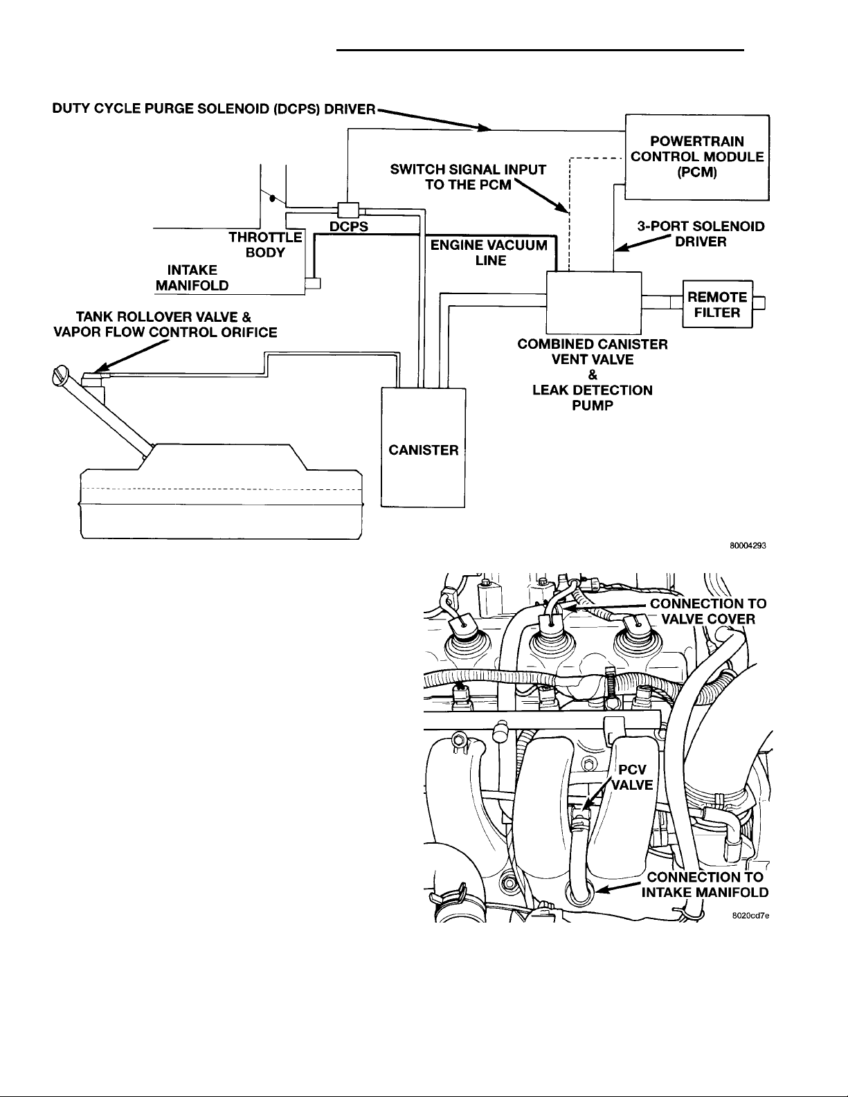
Fig. 4 Evaporative System Monitor Schematic
POSITIVE CRANKCASE VENTILATION (PCV) SYSTEMS
Intake manifold vacuum removes crankcase vapors
and piston blow-by from the engine. The emissions
pass through the PCV valve into the intake manifold
where they become part of the calibrated air-fuel
mixture. They are burned and expelled with the
exhaust gases. The air cleaner supplies make up air
when the engine does not have enough vapor or
blow-by gases. In this system, fresh air does not
enter the crankcase.
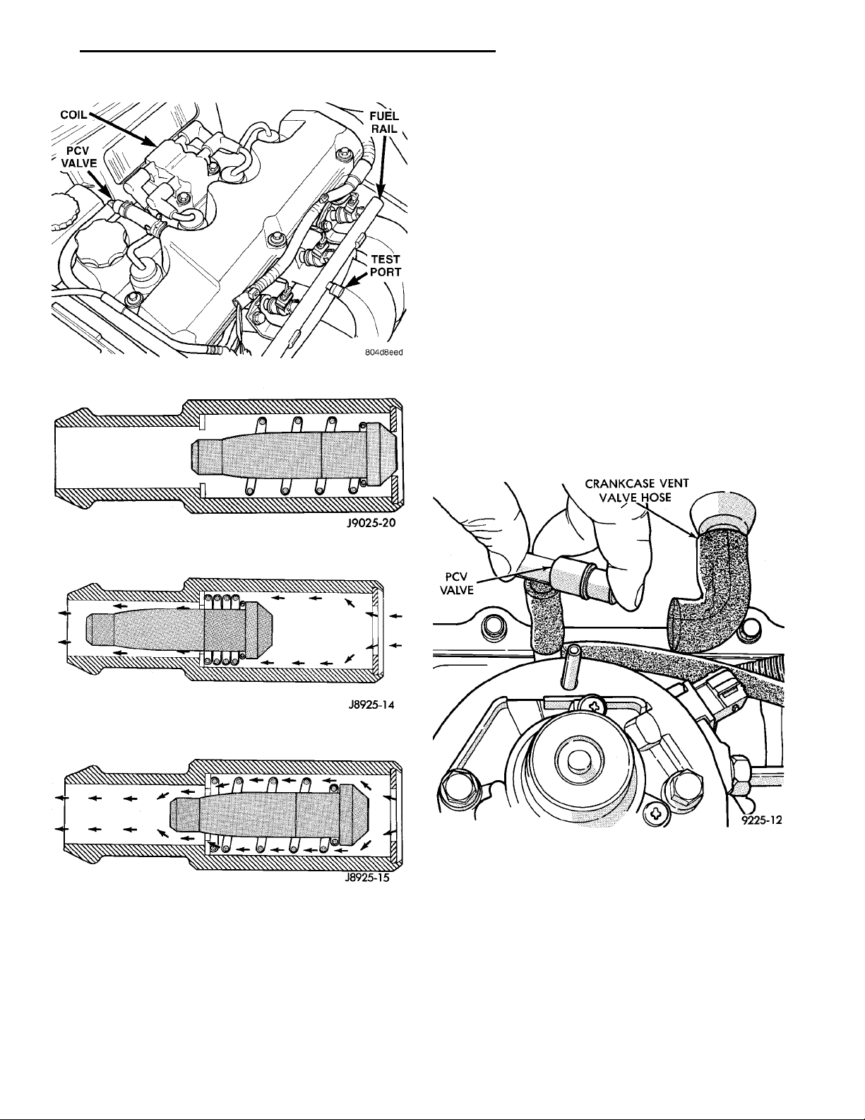
PCV VALVE
The PCV valve contains a spring loaded plunger.
The plunger meters the amount of crankcase vapors
routed into the combustion chamber based on intake
manifold vacuum.
When the engine is not operating or during an
engine backfire, the spring forces the plunger back
against the seat. This prevents vapors from flowing
through the valve (Fig. 7).
When the engine is at idle or cruising, high manifold vacuum is present. At these times manifold vacuum is able to completely compress the spring and
pull the plunger to the top of the valve (Fig. 8). In
this position there is minimal vapor flow through the
valve.
During periods of moderate intake manifold vacuum the plunger is only pulled part way back from
Fig. 5 PCV System—SOHC
the inlet. This results in maximum vapor flow
through the valve (Fig. 9).
Page 15
COIL
TESTPORTPCVVALVE
FUEL RAIL
CRANK-CASEVENTVALVEHOSE PCV VALVE
PL EMISSION CONTROL SYSTEMS 25 - 15
DESCRIPTION AND OPERATION (Continued)
The label contains the vehicle’s emission specifications and vacuum hose routings. All hoses must be
connected and routed according to the label.
If any difference exists between the VECI label on
the vehicle and the vacuum schematic in the Service
Manual, refer to the label on the vehicle.
DIAGNOSIS AND TESTING
LEAK DETECTION PUMP
Refer to the appropriate Powertrain Diagnostic
Procedures Manual for testing procedures.
PCV VALVE TEST
WARNING: APPLY PARKING BRAKE AND/OR
Fig. 6 PCV System—DOHC
BLOCK WHEELS BEFORE PERFORMING ANY TEST
OR ADJUSTMENT WITH THE ENGINE OPERATING.
With the engine idling, remove the PCV valve from
its attaching point. If the valve is operating properly,
a hissing noise will be heard and a strong vacuum
felt when placing a finger over the valve inlet (Fig.
Fig. 7 Engine Off or Engine Backfire—No Vapor
Flow
Fig. 8 High Intake Manifold Vacuum—Minimal Vapor
Flow
Fig. 9 Moderate Intake Manifold Vacuum—Maximum
Vapor Flow
VEHICLE EMISSION CONTROL INFORMATION LABEL
All models have a Vehicle Emission Control Information (VECI) Label. Chrysler permanently attaches
the label in the engine compartment. It cannot be
removed without defacing information and destroying
the label.
Fig. 10 PCV Test —Typical
10). With the engine off, shake the valve. The valve
should rattle when shaken. Replace the valve if it
does not operate properly. Do not attempt to clean
the PCV valve.
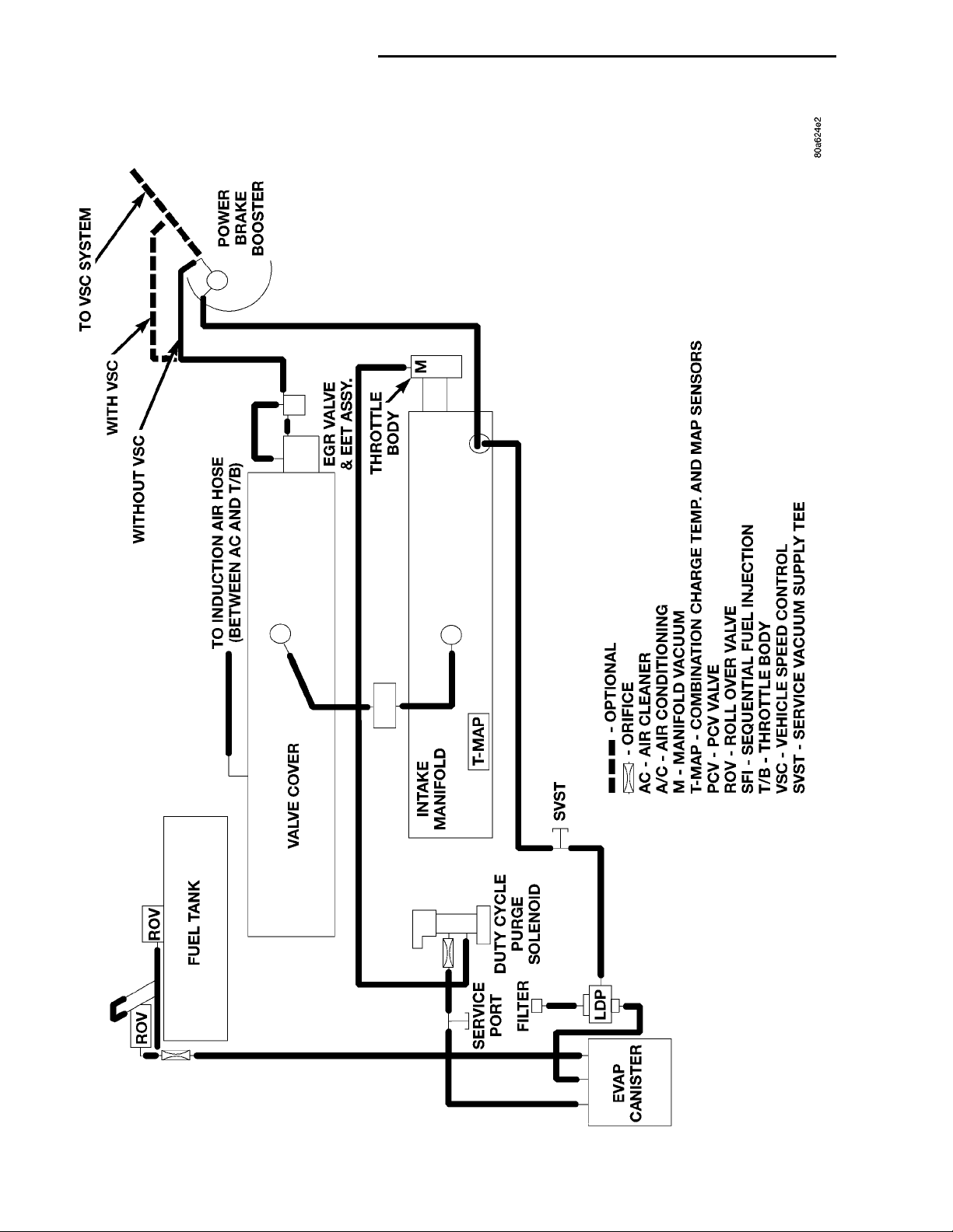
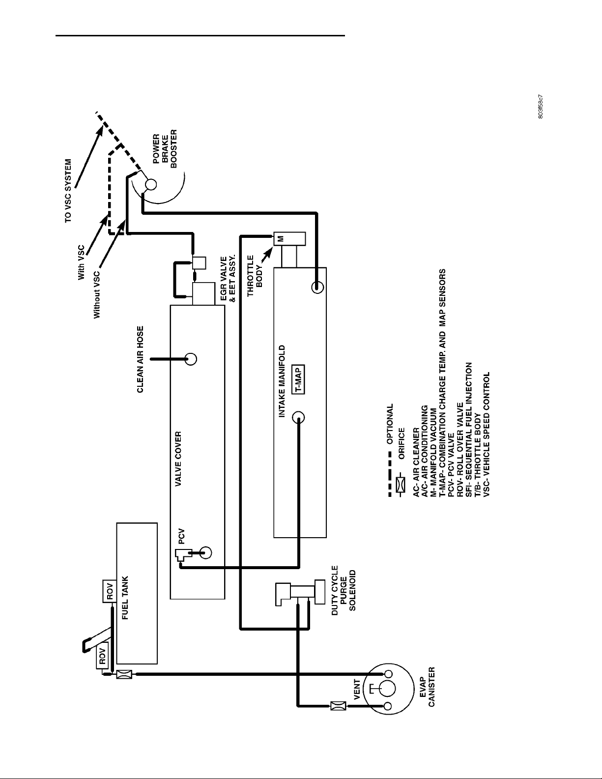
VACUUM SCHEMATIC
If any difference exists between the diagram on the
Vehicle Emission Control Information (VECI) label
and this illustration, refer to the label on the vehicle.
Page 16
25 - 16 EMISSION CONTROL SYSTEMS PL
DIAGNOSIS AND TESTING (Continued)
ENGINE VACUUM SCHEMATIC—SOHC
Page 17
PL EMISSION CONTROL SYSTEMS 25 - 17
DIAGNOSIS AND TESTING (Continued)
ENGINE VACUUM SCHEMATIC—DOHC
Page 18

25 - 18 EMISSION CONTROL SYSTEMS PL
REMOVAL AND INSTALLATION
LEAK DETECTION PUMP REPLACEMENT
REMOVAL
(1) Raise and support vehicle on a hoist.
(2) Remove right front wheel.
(3) Remove splash shield.
(4) Disconnect vacuum lines from EVAP canister.
(5) Push locking tab on electrical connector to
unlock and remove connector.
(6) Remove 3 nuts from EVAP canister and remove
canister.
(7) Remove pump and bracket as an assembly.
(8) Remove pump from bracket.
INSTALLATION
(1) Install pump to bracket and tighten bolts to 1.2
N·m (10.6 in. lbs.).
(2) Install pump and bracket assembly to body and
tighten bolts to 10 N·m (90 in. lbs.).
(3) Install EVAP canister to bracket and tighten
nutts to 5.6 N·m (50 in. lbs.).
(4) Install electrical connetor to pump and push
locking tab to lock.
(5) Before installing hoses to LDP, make sure
they are not cracked or split. If a hose leaks, it
will cause the Check Engine Lamp to illumunate. Connect lines to EVAP canister and LDP.
(6) Use the DRB scan tool, verify proper operation
of LDP.
(7) Install splash shield.
(8) Install wheel.
(9) Lower vehicle
Page 19
EGR VALVE
ELECTRICAL CONNECTION VACUUM SUPPLYEXHAUST BACKPRESSUREEGR VALVE
PL EMISSION CONTROL SYSTEMS 25 - 19
EXHAUST GAS RECIRCULATION (EGR) SYSTEM
INDEX
page page
DESCRIPTION AND OPERATION
EXHAUST GAS RECIRCULATION (EGR)
SYSTEM ............................ 19
DIAGNOSIS AND TESTING
EGR GAS FLOW TEST .................. 20
EGR SYSTEM ON-BOARD DIAGNOSTICS .... 20
EGR SYSTEM TEST .................... 20
DESCRIPTION AND OPERATION
EXHAUST GAS RECIRCULATION (EGR) SYSTEM
Refer to Monitored Systems - EGR Monitor in this
group for more information.
The EGR system reduces oxides of nitrogen (NOx)
in engine exhaust and helps prevent detonation
(engine knock). Under normal operating conditions,
engine cylinder temperature can reach more than
3000°F. Formation of NOx increases proportionally
with combustion temperature. To reduce the emission
of these oxides, the cylinder temperature must be
lowered. The system allows a predetermined amount
of hot exhaust gas to recirculate and dilute the
incoming air/fuel mixture. The diluted air/fuel mixture reduces peak flame temperature during combustion.
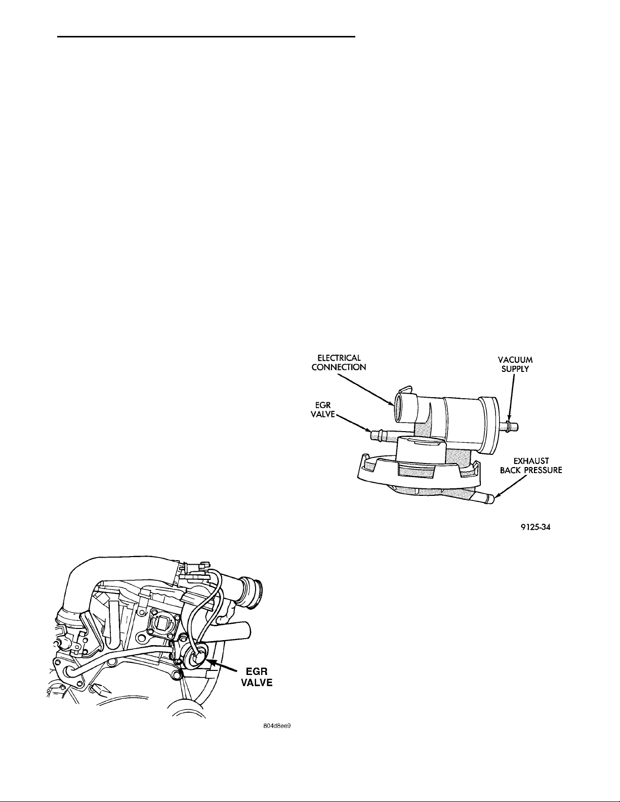
The EGR system consists of (Fig. 1):
• EGR tube
• EGR valve
• Electronic EGR Transducer (EET)
• Connecting hoses.
Fig. 1 EGR System
EGR VALVE CONTROL (TRANSDUCER)
TEST .............................. 22
EGR VALVE LEAKAGE TEST .............. 21
REMOVAL AND INSTALLATION
EGR TUBE ............................ 23
EGRVALVE ........................... 23
SPECIFICATIONS
TORQUE ............................. 23
The electronic EGR transducer contains an electrically operated solenoid and a back-pressure transducer (Fig. 2). The Powertrain Control Module (PCM)
operates the solenoid. The PCM determines when to
energize the solenoid. Exhaust system back- pressure
controls the transducer.
Fig. 2 Electronic EGR Transducer
When the PCM energizes the solenoid, vacuum
does not reach the transducer. Vacuum flows to the
transducer when the PCM de-energizes the solenoid.
When exhaust system back-pressure becomes high
enough, it fully closes a bleed valve in the transducer. When the PCM de-energizes the solenoid and
back-pressure closes the transducer bleed valve, vacuum flows through the transducer to operate the
EGR valve.
De-energizing the solenoid, but not fully closing the
transducer bleed hole (because of low back-pressure),
varies the strength of vacuum applied to the EGR
valve. Varying the strength of the vacuum changes
the amount of EGR supplied to the engine. This provides the correct amount of exhaust gas recirculation
for different operating conditions.
This system does not allow EGR at idle.
Page 20
25 - 20 EMISSION CONTROL SYSTEMS PL
DIAGNOSIS AND TESTING
EGR SYSTEM ON-BOARD DIAGNOSTICS
The PCM performs an on-board diagnostic check of
the EGR system. The diagnostic system uses the
electronic EGR transducer for the system tests.
The diagnostic check activates only during selected
engine/driving conditions. When the conditions are
met, the PCM energizes the transducer solenoid to
disable the EGR. The PCM checks for a change in
the heated oxygen sensor signal. If the air-fuel mixture goes lean, the PCM will attempt to enrichen the
mixture. The PCM registers a Diagnostic Trouble
Code (DTC) if the EGR system has failed or
degraded. After registering a DTC, the PCM turns on
the malfunction indicator (Check Engine) lamp. The
Malfunction Indicator Lamp (MIL) indicates the need
for service.
If a problem is indicated by the MIL and a DTC for
the EGR system is set, check for proper operation of
the EGR system. Use the System Test, EGR Gas
Flow Test and EGR Diagnosis Chart. If the EGR system tests properly, check the system using the DRB
scan tool. Refer to On-Board Diagnosis sections in
this Group. Also, refer to the DRB scan tool and the
appropriate Powertrain Diagnostics Procedure manual.
(5) After checking the system with the DRB scan
tool, proceed to the following EGR Valve Leakage and
EGR Valve Control Tests and repair as necessary.
EGR SYSTEM TEST
WARNING: APPLY PARKING BRAKE AND/OR
BLOCK WHEELS BEFORE TESTING THE EGR SYSTEM.
(1) Check the condition of all EGR system hoses
and tubes for leaks, cracks, kinks and hardening of
rubber hoses. Repair and correct these conditions
before performing any tests.
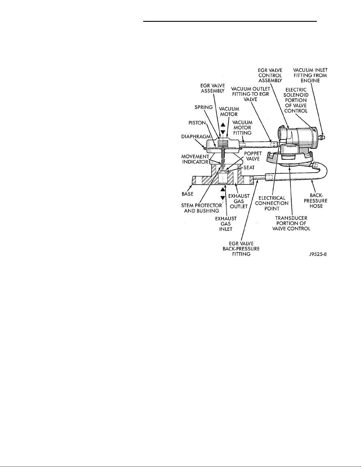
(2) Be sure the hoses at both the EGR valve and
EGR valve control are connected to the proper fittings (Fig. 3).
(3) Be sure the electrical connector is firmly connected at the valve control.
(4) To check EGR system operation, connect the
DRB scan tool to the 16–way data link connector.
The data link connector is located on the lower edge
of the instrument panel near the steering column.
Refer to the appropriate Powertrain Diagnostic Procedures service manual for operation of the DRB
scan tool when diagnosing the EGR system.
Fig. 3 EGR Value and EGR Value —Typical
EGR GAS FLOW TEST
Use the following test procedure to determine if
exhaust gas is flowing through the EGR valve. It can
also be used to determine if the EGR tube is plugged,
or the system passages in the intake or exhaust manifolds are plugged.
This is not to be used as a complete test of the
EGR system.
The engine must be started, running and warmed
to operating temperature for this test.
Page 21
VACUUM MOTOR FITTING(FROM VALVE CONTROL)BACK-PRESSURE FITTING(TO VALVE CONTROL)EGR VALVE ASSEMBLYVACUUM MOTOR
PL EMISSION CONTROL SYSTEMS 25 - 21
DIAGNOSIS AND TESTING (Continued)
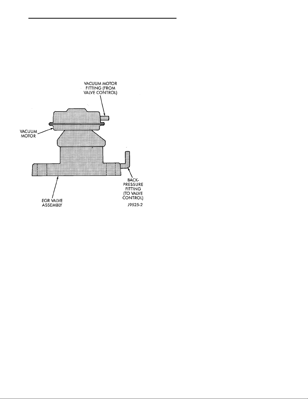
(1) All engines are equipped with two fittings
located on the EGR valve (Fig. 4). The upper fitting
(located on the vacuum motor) supplies engine vacuum to a diaphragm within the EGR valve for valve
operation. The lower fitting (located on the base of
the EGR valve) is used to supply exhaust back-pressure to the EGR valve control.
Fig. 4 Typical EGR Valve
(2) Disconnect the rubber hose at the vacuum
motor fitting (Fig. 4) on the top of the EGR valve
vacuum motor.
(3) Connect a hand-held vacuum pump to this fitting.
(4) Start the engine.
(5) Slowly apply 5 inches of vacuum to the fitting
on the EGR valve motor.
(6) While applying vacuum, a minimum of 3 inches
of vacuum, and with the engine running at idle
speed, the idle speed should drop or the engine may
even stall, if the vacuum is applied quickly. This is
indicating that exhaust gas is flowing through the
EGR tube between the intake and exhaust manifolds.
(7) If the engine speed did not change, the EGR
valve may be defective, or EGR tube may be plugged
with carbon, or the passages in the intake and
exhaust manifolds may be plugged with carbon.
(a) Remove EGR valve from engine. Refer to
EGR Valve Removal in this group.
(b) Apply vacuum to the vacuum motor fitting
and observe the stem on the EGR valve. If the
stem is moving, it can be assumed that the EGR
valve is functioning correctly. The problem is in
either a plugged EGR tube or plugged passages at
the intake or exhaust manifolds, refer to step (c). If
the stem will not move, replace the EGR valve.
Note: The EGR valve, valve control and attaching
hoses are serviced as one unit. Refer to EGR Valve
Removal/Installation in this group.
(c) Remove the EGR tube between the intake
and exhaust manifolds. Check and clean the EGR
tube and its related openings on the manifolds.
Refer to EGR Tube in this group for procedures.
(8) Do not attempt to clean the EGR valve. If the
valve shows evidence of heavy carbon build-up near
the base, replace it.
EGR VALVE LEAKAGE TEST
This is not to be used as a complete test of the
EGR system.
If the engine will not idle, dies out on idle, or idle
is rough or slow, the poppet valve (Fig. 3) at the base
of the EGR valve may be leaking in the closed position.
(1) The engine should be off for the following test.
(2) Disconnect the rubber hose from the fitting
(Fig. 3) at the top (vacuum motor) side of the EGR
valve.
(a) Connect a hand-held vacuum pump to this
fitting.
(b) Apply 15 inches of vacuum to the pump.
(c) Observe the gauge reading on the pump.
(d) If vacuum falls off, the diaphragm in the
EGR valve has ruptured.
(e) Replace the EGR valve. Note: The EGR
valve, valve control and attaching hoses are serviced as one assembly. Refer to EGR Valve Removal/Installation in this group.
(f) Proceed to the next step.
(3) A small metal fitting (back-pressure fitting) is
located at the base of the EGR valve (Fig. 3). A rubber back-pressure hose connects it to the back-pressure fitting on the EGR valve control. Disconnect this
rubber hose at the EGR valve fitting.
(4) Remove the air cleaner housing from the throt-
tle body.
(5) Using compressed air, and using an air nozzle
with a rubber tip, apply approximately 50 psi of regulated shop air to the metal back- pressure fitting on
the EGR valve.
(6) By hand, open the throttle to the wide open
position. Air SHOULD NOT BE HEARD emitting
from the intake manifold while applying air pressure
at the back-pressure fitting.
(7) If air CAN BE HEARD emitting from the
intake manifold, the poppet valve (Fig. 3) is leaking
at the bottom of the EGR valve. Replace the EGR
valve. Note: The EGR valve, valve control and
attaching hoses are serviced as one assembly. Refer
to EGR Valve Removal/Installation in this group. Do
not attempt clean the old EGR valve.
Page 22

25 - 22 EMISSION CONTROL SYSTEMS PL
DIAGNOSIS AND TESTING (Continued)
EGR VALVE CONTROL (TRANSDUCER) TEST
TESTING ELECTRICAL SOLENOID PORTION OF VALVE
This is not to be used as a complete test of the
EGR system.
Electrical operation of the valve should be checked
with the DRB scan tool. Refer to the appropriate
Powertrain Diagnostic Procedures service manual for
operation of the DRB scan tool. Replace solenoid if
necessary, unit serviced only as an assembly.
TESTING VACUUM TRANSDUCER PORTION OF VALVE
The first part of this test will determine if the
transducer diaphragm at the back-pressure side of
the valve has ruptured or is leaking. The second part
of the test will determine if engine vacuum (full-manifold) is flowing from the inlet to the outlet side of
the valve. This is not to be used as a complete test of
the EGR system.
(1) Disconnect the rubber back-pressure hose from
the fitting at the bottom of EGR valve (Fig. 3).
(2) Connect a hand-held vacuum pump to this fitting.
(3) Apply 10 inches of vacuum to this fitting.
(4) If vacuum falls off, the valve diaphragm is
leaking.
(5) Replace the EGR valve assembly. Proceed to
next step for further testing.
(6) Remove the rubber hose at the vacuum inlet
fitting (Fig. 3) on the EGR valve.
(7) Connect a vacuum gauge to this disconnected
hose.
(8) Start the engine and bring to operating temperature. Hold engine speed at approximately 1500
rpm.
(9) Check for steady engine vacuum (full-manifold)
at this hose.
(10) If engine vacuum (full-manifold) is not
present, check vacuum line to engine and repair as
necessary before proceeding to next step.
(11) Reconnect the rubber hose to the vacuum
inlet fitting (Fig. 3) on the EGR valve.
(12) Disconnect the rubber hose at the vacuum
outlet fitting (Fig. 3) on the EGR valve.
(13) Connect a vacuum gauge to this fitting.
(14) Disconnect the electrical connector (Fig. 3) at
the valve control. This will simulate an open circuit
(no ground from the PCM) at the valve.
(15) Start the engine and bring to operating temperature.
(16) Hold the engine speed to approximately 2000
rpm while checking for engine vacuum (full-manifold)
at this fitting. To allow full manifold vacuum to
flow through the valve, exhaust back-pressure
must be present at valve. It must be high
enough to hold the bleed valve in the transducer portion of the valve closed. Have a helper
momentarily (a second or two) hold a rag over the
tailpipe opening to build some exhaust back-pressure
while observing the vacuum gauge. Heavy gloves
should be worn. Do not cover the tailpipe open-
ing for an extended period of time as damage to
components or overheating may result.
(17) As temporary back-pressure is built, full manifold vacuum should be observed at the vacuum outlet fitting. Without back-pressure, and engine at
approximately 2000 rpm, the gauge reading will be
low. This low reading is normal. At idle speed, the
gauge reading will be erratic. This is also normal.
(18) If full manifold vacuum is not present at the
outlet fitting, but was present at the inlet fitting,
replace the valve. Note: The EGR valve, valve control
and attaching hoses are serviced as one assembly.
Refer to EGR Valve Removal/Installation in this
group.
Page 23
PL EMISSION CONTROL SYSTEMS 25 - 23
REMOVAL AND INSTALLATION
EGR VALVE
If the EGR system operates incorrectly, replace the
entire EGR valve and transducer together. The EGR
valve and electrical transducer (EET) are calibrated
together.
REMOVAL
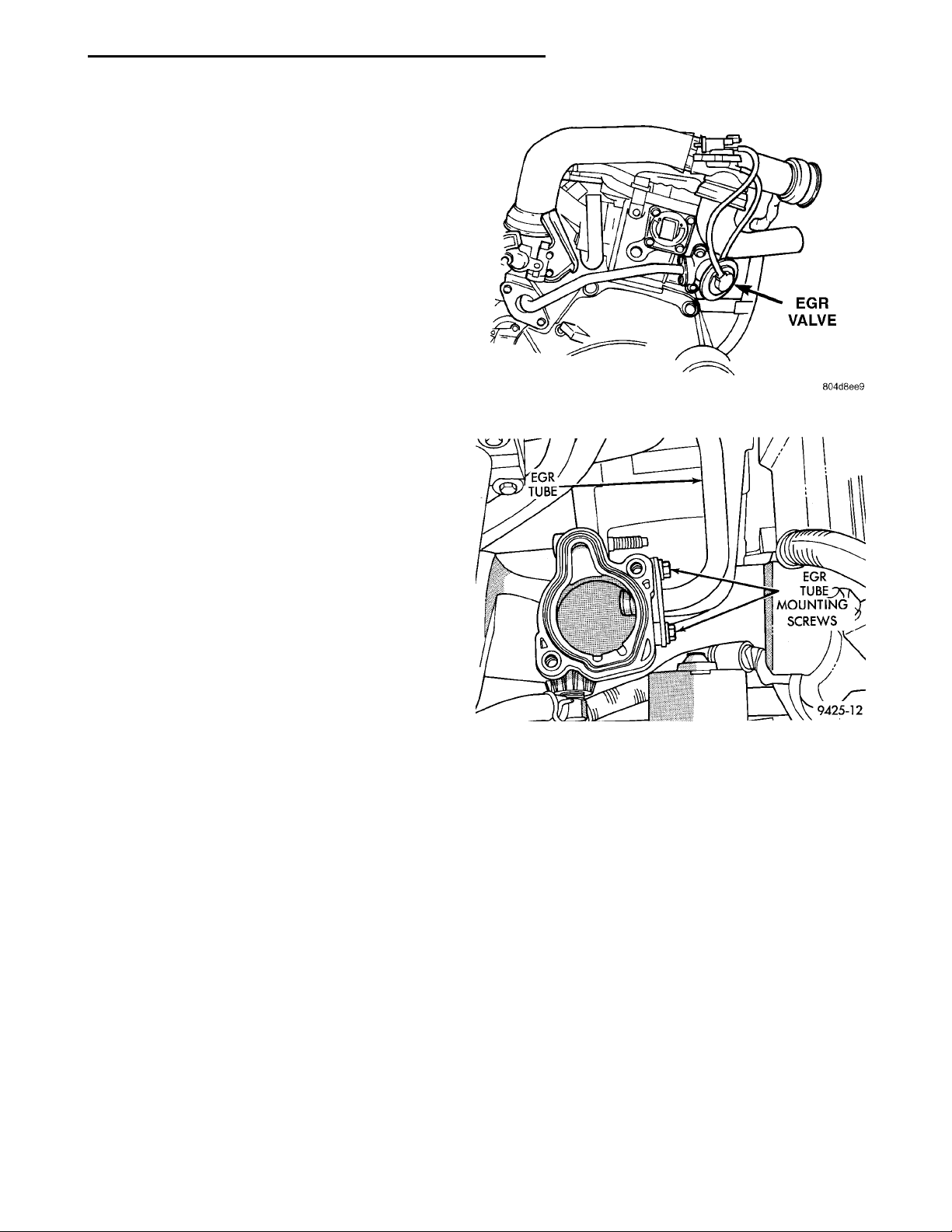
The EGR valve attaches to the rear of the cylinder
head (Fig. 5). EGR transducer is attached to the air
inlet duct.
(1) Remove EGR transducer from air inlet duct.
(2) Disconnect vacuum supply tube from EGR
transducer solenoid.
(3) Disconnect electrical connector from solenoid.
(4) Remove air inlet duct.
(5) Remove EGR tube to EGR valve screws.
(6) Remove EGR valve mounting screws. Remove
EGR valve and transducer.
(7) Clean gasket surfaces. Discard old gaskets. If
necessary, clean EGR passages.
EGRTUBE EGR TUBEMOUNTINGSCREWS
Fig. 5 EGR System
INSTALLATION
(1) Loosely install EGR valve with new gaskets.
(2) Finger tighten EGR tube fasteners.
(3) Tighten EGR tube fasteners to 11 N·m (95 in.
lbs.) torque.
(4) Tightening EGR valve mounting screws to 22
N·m (200 in. lbs.) torque.
(5) Install air inlet duct.
(6) Connect vacuum supply tube to solenoid.
(7) Attach electrical connector to solenoid.
(8) Install EGR transducer onto air inlet duct.
EGR TUBE
The EGR tube attaches to the intake manifold plenum below the throttle body and EGR valve.
REMOVAL
(1) Remove screws attaching EGR tube to intake
manifold (Fig. 6).
(2) Remove EGR tube to EGR valve screws.
(3) Remove EGR tube. Clean gasket surface on the
EGR valve. Wipe clean the grommet on the intake
manifold.
INSTALLATION
The rubber grommet that seals the EGR tube to
intake manifold connection is reusable.
(1) Loosely install the EGR tube and fasteners.
Fig. 6 EGR Tube Stud Bolts
(2) Tighten the EGR tube to intake manifold ple-
num screws to 11 N·m (95 in. lbs) torque.
(3) Tighten the EGR tube to EGR valve screws to
11 N·m (95 in. lbs.) torque.
SPECIFICATIONS
TORQUE
Description Torque
EGR valve to cyl. head .......22N·m(200 in. lbs.)
EGR tube to EGR valve ...........11(95in.lbs.)
EGR tube to intake manifold . . . 11 N·m (95 in. lbs.)
Page 24

 Loading...