

Page 1

PL HEATING AND AIR CONDITIONING 24 - 1
HEATING AND AIR CONDITIONING
CONTENTS
page page
GENERAL INFORMATION
INTRODUCTION ........................ 1
SAFETY PRECAUTIONS AND WARNINGS .... 2
DESCRIPTION AND OPERATION
A/C REFRIGERANT LINES ................ 3
BLOWER MOTOR RESISTOR .............. 3
COMPRESSOR FRONT SHAFT SEAL ........ 4
COMPRESSOR ......................... 4
CONDENSATION DRAIN TUBE ............. 4
ENGINE COOLING SYSTEM REQUIREMENTS . 4
EVAPORATOR PROBE ................... 4
HANDLING TUBING AND FITTINGS .......... 4
HIGH PRESSURE CUT OUT SWITCH ........ 5
LOW PRESSURE CUT OFF SWITCH ......... 5
SIDE WINDOW DEMISTERS ............... 5
SYSTEM AIRFLOW ...................... 5
SYSTEM OIL LEVEL ..................... 6
VACUUM CONTROL SYSTEM .............. 6
DIAGNOSIS AND TESTING
A/C PERFORMANCE TEST ................ 6
BLOWER MOTOR ELECTRICAL DIAGNOSIS . . . 7
BLOWER MOTOR VIBRATION AND/OR NOISE
DIAGNOSIS .......................... 7
COMPRESSOR NOISE DIAGNOSIS .......... 7
EVAPORATOR PROBE TEST .............. 10
EXPANSION VALVE ..................... 10
HEATER PERFORMANCE TEST ........... 11
LOW PRESSURE CUT-OFF SWITCH ........ 11
SYSTEM CHARGE LEVEL TEST ........... 12
VACUUM CONTROL SYSTEM ............. 13
SERVICE PROCEDURES
CHARGING A/C SYSTEM ................. 14
EVACUATING REFRIGERANT SYSTEM ...... 15
R-134a REFRIGERANT .................. 16
SERVICING REFRIGERANT OIL LEVEL ...... 16
SYSTEM LEAK CHECKING ............... 17
REMOVAL AND INSTALLATION
A/C FILTER/DRIER ...................... 23
A/C SERVICE PORT VALVE CORES ........ 18
BLOWER MOTOR AND WHEEL ASSEMBLY . . . 18
BLOWER MOTOR RESISTOR ............. 19
BLOWER MOTOR WHEEL ................ 19
COMPRESSOR CLUTCH/COIL ASSEMBLY . . . 19
COMPRESSOR ........................ 19
CONDENSATION DRAIN TUBE ............ 21
CONDENSER .......................... 21
DISCHARGE LINE ...................... 22
EVAPORATOR PROBE .................. 22
EVAPORATOR ......................... 22
EXPANSION VALVE ..................... 23
HEATER CORE ........................ 24
HEATER HOSES ....................... 24
HIGH PRESSURE CUT OUT SWITCH ....... 24
HIGH PRESSURE RELIEF VALVE .......... 24
LIQUID LINE .......................... 25
LOW PRESSURE CUT OFF SWITCH ........ 25
MODE CONTROL CABLE ................. 25
RECIRCULATION CONTROL CABLE (RHD) . . . 26
RECIRCULATION DOOR ACTUATOR ........ 26
SUCTION LINE ........................ 26
TEMPERATURE CONTROL CABLE ......... 26
UNIT HOUSING ........................ 28
DISASSEMBLY AND ASSEMBLY
AIR DISTRIBUTION MODULE –
RECONDITION ....................... 29
ADJUSTMENTS
MODE CONTROL CABLE ................. 31
RECIRCULATION CONTROL CABLE (RHD) . . . 31
TEMPERATURE CONTROL CABLE ......... 31
GENERAL INFORMATION
INTRODUCTION
Both the heater and the heater/air conditioning
systems share many of the same functioning components. This group will deal with both systems
together when component function is common, and
separately when they are not.
For proper operation of the instrument panel controls, refer to the Owner’s Manual provided with the
vehicle.
The unit housing is divided into two sides. The left
side is called the air distribution module. The air distribution module is the same on vehicles with or
without air conditioning. On the right side there is
either a blower module (non-A/C vehicles) or an evaporator/blower module (vehicles with A/C). The blower
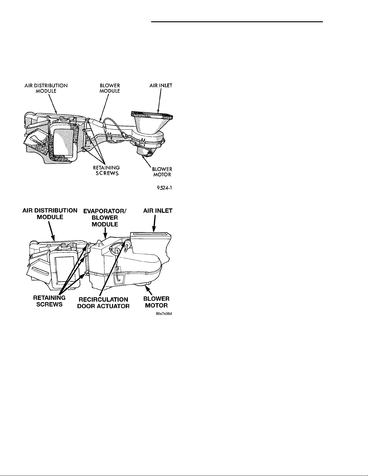
module is unique to heater only systems (Fig. 1).
The air distribution module contains the heater
core and doors used to control air flow. The vehicle
uses the same air distribution module on all models
(with or without air conditioning).
Page 2
AIR DISTRIBUTION MODULE BLOWER MODULE AIR INLETBLOWER MOTORRETAINING SCREWS
AIR DISTRIBUTION MODULEEVAPORATOR/BLOWERMODULEAIR INLETBLOWER MOTORRECIRCULATION DOORACTUATORRETAINING SCREWS
24 - 2 HEATING AND AIR CONDITIONING PL
GENERAL INFORMATION (Continued)
The air conditioning evaporator is located in the
evaporator/blower module (Fig. 2).
To service the heater core, evaporator and/or any of
the air doors the unit housing must be removed from
the vehicle.
Fig. 1 Heater Only Unit Housing
Fig. 2 A/C Heater Unit Housing
NOTE: This group covers both Left-Hand Drive
(LHD) and Right-Hand Drive (RHD) versions of this
model. Whenever required and feasible, the RHD
versions of affected vehicle components have been
constructed as mirror-image of the LHD versions.
While most of the illustrations used in this group
represent only the LHD version, the diagnostic and
service procedures outlined can generally be
applied to either version. Exceptions to this rule
have been clearly identified as LHD, RHD, or Export
if a special illustration or procedure is required.
SAFETY PRECAUTIONS AND WARNINGS
WARNING: WEAR EYE PROTECTION WHEN SERVICING THE AIR CONDITIONING REFRIGERANT
SYSTEM. SERIOUS EYE INJURY CAN RESULT
FROM EYE CONTACT WITH REFRIGERANT. IF EYE
CONTACT IS MADE, SEEK MEDICAL ATTENTION
IMMEDIATELY.
DO NOT EXPOSE REFRIGERANT TO OPEN
FLAME. POISONOUS GAS IS CREATED WHEN
REFRIGERANT IS BURNED. AN ELECTRONIC TYPE
LEAK DETECTOR IS RECOMMENDED.
LARGE AMOUNTS OF REFRIGERANT RELEASED
IN A CLOSED WORK AREA WILL DISPLACE THE
OXYGEN AND CAUSE SUFFOCATION.
THE EVAPORATION RATE OF REFRIGERANT AT
AVERAGE TEMPERATURE AND ALTITUDE IS
EXTREMELY HIGH. AS A RESULT, ANYTHING THAT
COMES IN CONTACT WITH THE REFRIGERANT
WILL FREEZE. ALWAYS PROTECT SKIN OR DELICATE OBJECTS FROM DIRECT CONTACT WITH
REFRIGERANT. R-134a SERVICE EQUIPMENT OR
VEHICLE A/C SYSTEM SHOULD NOT BE PRESSURE TESTED OR LEAK TESTED WITH COMPRESSED AIR.
SOME MIXTURES OF AIR and R-134a HAVE BEEN
SHOWN TO BE COMBUSTIBLE AT ELEVATED
PRESSURES. THESE MIXTURES ARE POTENTIALLY
DANGEROUS AND MAY RESULT IN FIRE OR
EXPLOSION CAUSING INJURY OR PROPERTY
DAMAGE.
ANTIFREEZE IS AN ETHYLENE GLYCOL BASE
COOLANT AND IS HARMFUL IF SWALLOWED OR
INHALED. SEEK MEDICAL ATTENTION IMMEDIATELY IF SWALLOWED OR INHALED. DO NOT
STORE IN OPEN OR UNMARKED CONTAINERS.
WASH SKIN AND CLOTHING THOROUGHLY AFTER
COMING IN CONTACT WITH ETHYLENE GLYCOL.
KEEP OUT OF REACH OF CHILDREN AND PETS.
DO NOT OPEN A COOLING SYSTEM WHEN THE
ENGINE IS AT RUNNING TEMPERATURE. PERSONAL INJURY CAN RESULT.
CAUTION: The engine cooling system is designed
to develop internal pressure of 97 to 123 kPa (14 to
18 psi). Allow the vehicle to cool a minimum of 15
minutes before opening the cooling system. Refer
to Group 7, Cooling System.
Page 3
PL HEATING AND AIR CONDITIONING 24 - 3
DESCRIPTION AND OPERATION
A/C REFRIGERANT LINES
HIGH SIDE SERVICE PORTFILTER/DRIERTO EXPANSION VALVETO CONDENSERTO COMPRESSORSUCTION LINELOW SIDE SERVICE PORTLIQUID LINE
DISCHARGE LINE
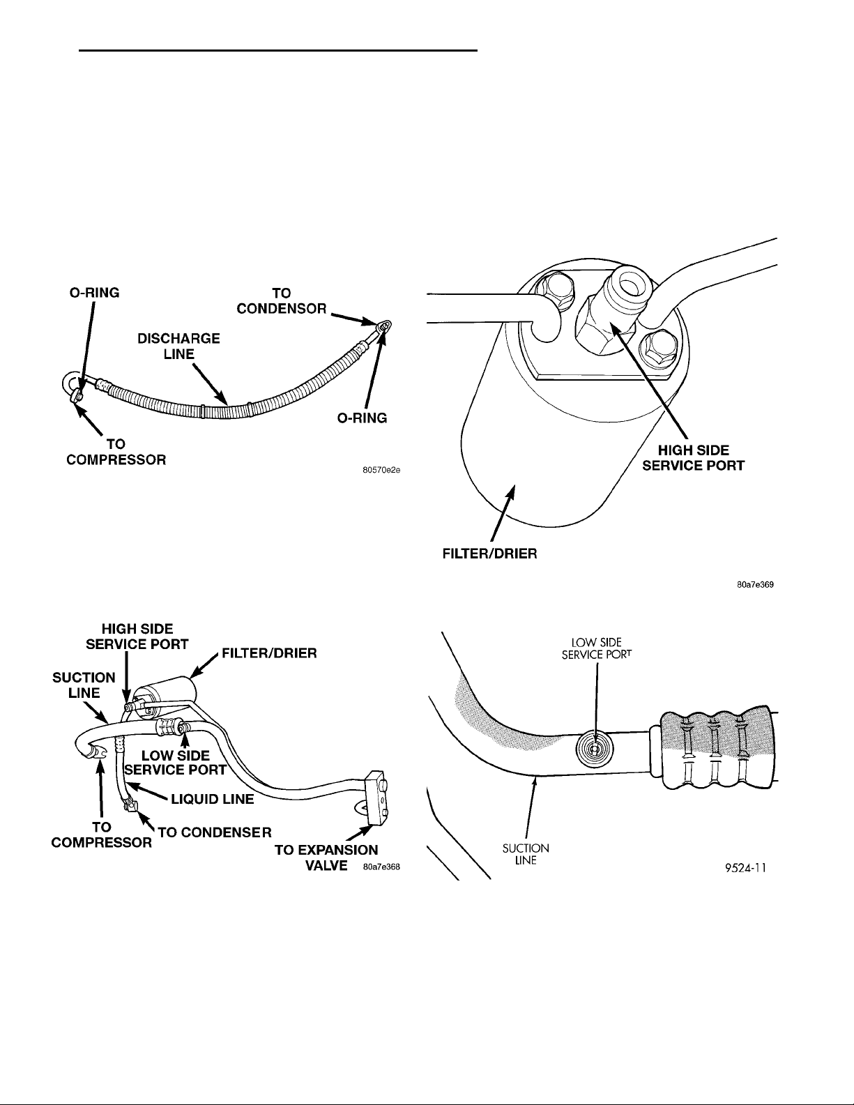
compressor to the condenser (Fig. 3). It has no serviceable parts except the rubber O- rings. If the line
is found to be leaking or is damaged it must be
replaced as an assembly.
LIQUID LINE
denser to drier (Fig. 4). It has no serviceable parts
except the rubber O-rings. If the line is found to be
leaking or is damaged it must be replaced as an
assembly.
O-RING DISCHARGE LINE TO CONDENSORO-RINGTO COMPRESSOR
The discharge line is the line that goes from the
Fig. 3 Discharge Line
The liquid line is the line that goes from the con-
There are no serviceable parts on the suction line
other than the rubber O-rings and expansion valve
gasket. If the line is found to be leaking or is damaged it must be replaced as an assembly.
FILTER/DRIERHIGH SIDE SERVICE PORT
LOW SIDE SERVICE PORTSUCTION LINE
A/C SERVICE PORT VALVE CORES
The A/C service port valve cores are serviceable
(Fig. 5) and (Fig. 6).
Fig. 5 High Side Service Port Valve
Fig. 4 Liquid/Suction Line
SUCTION LINE
The suction line is the large line that connects to
the expansion valve and goes to the compressor (Fig.
4). It also has a small line that goes to the filter/
drier. The suction line uses a gasket on the expansion valve side and rubber O-rings on all other
connections.
Fig. 6 Low Side Service Port Valve
BLOWER MOTOR RESISTOR
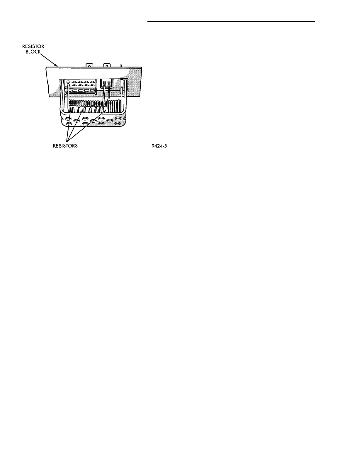
The blower motor resistor is located in the cowl, at
the base of the windshield. There are two different
resistor blocks depending on whether the vehicle is
equipped with A/C or not. The blower motor resistors
will get hot when in use. Do not touch resistor block
if the blower motor has been running (Fig. 7).
Page 4
RESISTOR BLOCKRESISTORS
24 - 4 HEATING AND AIR CONDITIONING PL
DESCRIPTION AND OPERATION (Continued)
CONDENSATION DRAIN TUBE
Condensation that accumulates in the evaporator
housing is drained from a tube through the dash and
on to the ground. This tube must be kept open to
prevent condensate water from collecting in the bottom of the housing.
The tapered end of the drain tube is designed to
keep contaminants from entering the heater A/C unit
housing. If the tube is pinched or blocked, condensate
cannot drain, causing water to back up and spill into
the passenger compartment. It is normal to see condensate drainage below the vehicle. If the tube is
damaged, it should be replaced.
ENGINE COOLING SYSTEM REQUIREMENTS
To maintain ample temperature levels from the
Fig. 7 Resistor Block
COMPRESSOR
The compressor used on this vehicle is a Nippondenso 10PA17 R-134a. This compressor uses an aluminum swash plate, teflon coated pistons and
aluminum sleeved cylinder walls.
CAUTION: A 10PA17 R-12 compressor looks identical to a 10PA17 R-134a and will bolt up to the vehicle. The 10PA17 R-12 compressor must not be used
on this system. It is extremely important that a
10PA17 R-134a compressor is identified prior to
using compressor in question. Check tag located
on compressor for model number.
NOISE
Excessive noise that occurs when the air conditioning is being used may be caused by:
• Loose bolts
• Mounting brackets
• Loose compressor clutch
• Excessive high refrigerant operating pressure
Verify the following before compressor repair is
performed:
(1) Compressor drive belt condition
(2) Proper refrigerant charge
(3) Thermal expansion valve (TXV) operating correctly
(4) Head pressure is normal
COMPRESSOR FRONT SHAFT SEAL
The compressor front shaft seal is not serviceable.
If a leak is detected at the shaft seal, the compressor
must be replaced as a unit.
heating-A/C system, the cooling system must be in
proper working order. Refer to Group 0, Lubrication
and Maintenance or Group 7, Cooling System of this
manual.
The use of a bug screen is not recommended. Any
obstructions forward of the condenser can reduce the
effectiveness of the air conditioning system.
EVAPORATOR PROBE
The evaporator probe can be replaced without having to remove the unit housing from the vehicle.
The evaporator probe is located in the unit housing
and placed in the evaporator fins. The probe prevents
evaporator freeze-up. This is done by cycling the compressor clutch OFF when evaporator temperature
drops below freeze point. It cycles ON when the
evaporator temperature rises above freeze point. The
evaporator probe uses a thermistor probe in a capillary tube. The tube is inserted between the evaporator fins in the heater-A/C unit housing.
HANDLING TUBING AND FITTINGS
Kinks in the refrigerant tubing or sharp bends in
the refrigerant hose lines will greatly reduce the
capacity of the entire system. High pressures are produced in the system when it is operating. Extreme
care must be exercised to make sure that all connections are pressure tight. Dirt and moisture can enter
the system when it is opened for repair or replacement of lines or components. The refrigerant oil will
absorb moisture readily out of the air. This moisture
will convert into acids within a closed system.
Page 5
HIGH PRESSURERELIEF VALVECOMPRESSORMANIFOLD HIGH PRES-SURE CUT-OUTSWITCH
EXPANSION VALVELOW PRESSURE CUT OFFSWITCHSUCTION LINECONTROL HEAD
PL HEATING AND AIR CONDITIONING 24 - 5
DESCRIPTION AND OPERATION (Continued)
CAUTION: The system must be completely empty
before opening any fitting or connection in the
refrigeration system. Open fittings with caution
even after the system has been emptied. If any
pressure is noticed as a fitting is loosened,
retighten fitting and evacuate the system again.
A good rule for the flexible hose lines is to keep
the radius of all bends at least 10 times the diameter of the hose. Sharper bends will reduce the flow
of refrigerant. The flexible hose lines should be
routed so they are at least 3 inches (80 mm) from
the exhaust manifold. Inspect all flexible hose lines
to make sure they are in good condition and properly routed.
The use of correct wrenches when making connections is very important. Improper wrenches or
improper use of wrenches can damage the fittings.
The internal parts of the A/C system will remain
stable as long as moisture-free refrigerant and
refrigerant oil is used. Abnormal amounts of dirt,
moisture or air can upset the chemical stability.
This may cause operational troubles or even serious damage if present in more than very small
quantities.
When opening a refrigeration system, have everything you will need to repair the system ready. This
will minimize the amount of time the system must
be opened. Cap or plug all lines and fittings as
soon as they are opened. This will help prevent the
entrance of dirt and moisture. All new lines and
components should be capped or sealed until they
are ready to be used.
All tools, including the refrigerant dispensing
manifold, the manifold gauge set, and test hoses
should be kept clean and dry.
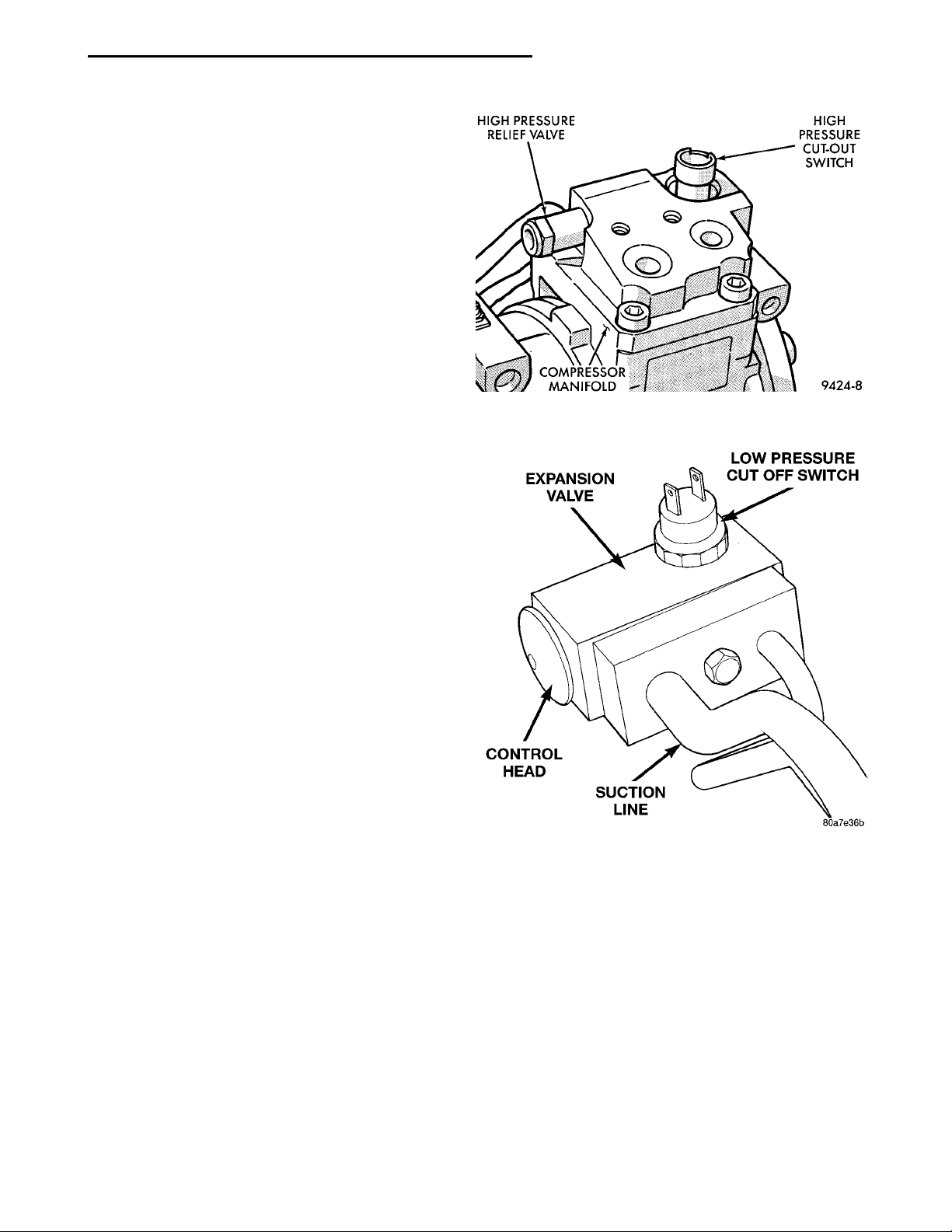
Fig. 8 High Pressure Cut Out Switch Location
HIGH PRESSURE CUT OUT SWITCH
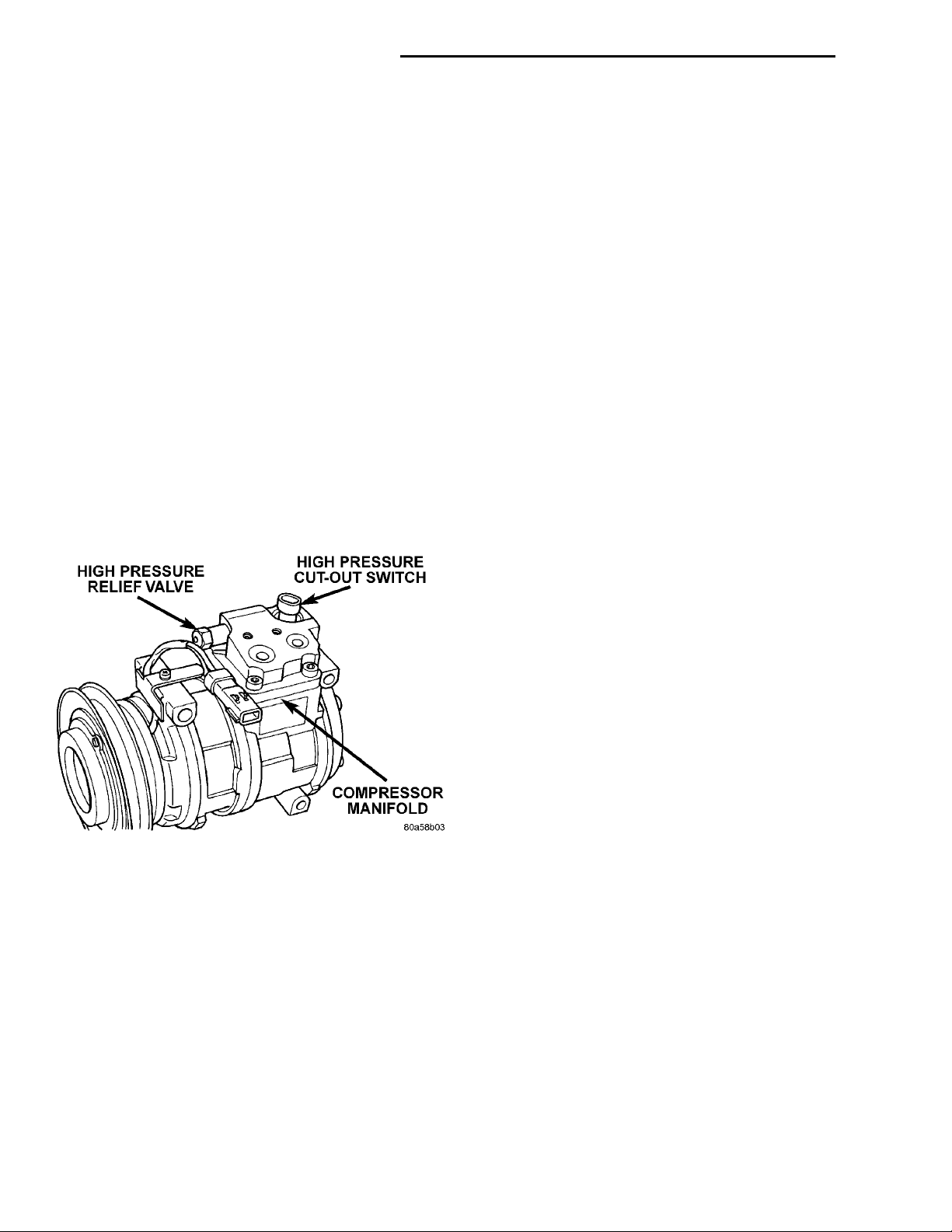
The high pressure cut out switch is located in the
compressor manifold (Fig. 8). It turns off the compressor if the system pressure exceeds 3240 kPa (470
psi)
LOW PRESSURE CUT OFF SWITCH
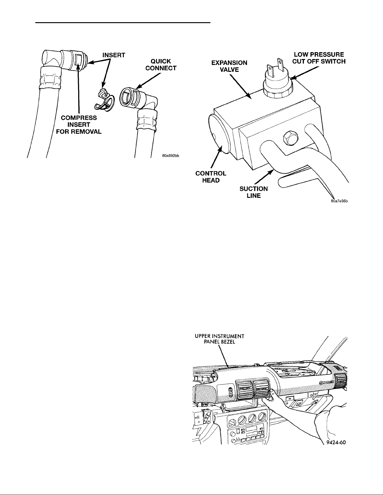
The Low Pressure Cut Off Switch (Fig. 9) monitors
the refrigerant gas pressure on the suction side of
the system. The low pressure cut off switch is located
on the expansion valve. The low pressure cut off
switch turns off voltage to the compressor clutch coil
when refrigerant gas pressure drops to levels that
could damage the compressor. The low pressure cut
out switch is a sealed factory calibrated unit. It must
be replaced if defective.
SIDE WINDOW DEMISTERS
The demisters direct air from the unit housing
through the outlets located on the top corners of the
Fig. 9 Low Pressure Cut Off Switch
instrument panel. The demisters operate when the
mode selector is anywhere between floor and defrost
settings. Some air may be noticeable from the demister outlets when the mode selector is in the bilevel to
floor positions.
SYSTEM AIRFLOW
The system pulls outside (ambient) air through the
cowl opening at the base of the windshield. Then it
goes into the plenum chamber above the unit housing. On air conditioned vehicles, the air passes
through the evaporator. Air flow can be directed
either through or around the heater core. This is
done by adjusting the blend-air door with the TEMP
control on the instrument panel. The air flow can
then be directed from the panel, floor and defrost
Page 6
24 - 6 HEATING AND AIR CONDITIONING PL
DESCRIPTION AND OPERATION (Continued)
outlets in various combinations using the mode selector. There are 17 different mode selections possible.
Air flow velocity can be adjusted with the blower
speed selector switch on the instrument panel.
On A/C equipped vehicles the ambient air intake
can be controlled by opening and closing the recirculating air door. When placed in RECIRC, air that is
inside vehicle is removed continuously and recirculated through unit housing. Ambient air cannot be
controlled on vehicles without A/C. The system uses
outside air at all times.
The air conditioning compressor can be engaged by
turning the fan switch counterclockwise from the off
position. It can also be engaged by placing the mode
control in the defrost position. This will remove heat
and humidity from the air before it is directed
through or around the heater core.
SYSTEM OIL LEVEL
It is important to have the correct amount of oil in
the A/C system to ensure proper lubrication of the
compressor. Too little oil will result in damage to the
compressor. Too much oil will reduce the cooling
capacity of the system and consequently result in
higher discharge air temperatures.
NOTE: The oil used in the compressor is ND8 PAG
R-134a refrigerant oil. Only refrigerant oil of the
same type should be used to service the system.
Do not use any other oil. The oil container should
be kept tightly capped until it is ready for use.
Tightly cap afterwards to prevent contamination
from dirt and moisture. Refrigerant oil will quickly
absorb any moisture it comes in contact with. Special effort must be used to keep all R-134a system
components moisture-free. Moisture in the oil is
very difficult to remove and will cause a reliability
problem with the compressor.
It will not be necessary to check oil level in the
compressor or to add oil unless there has been an oil
loss. Oil loss at a leak point will be evident by the
presence of a wet, shiny surface around the leak.
REFRIGERANT OIL LEVEL CHECK
When an air conditioning system is first assembled, all components (except the compressor) are
refrigerant oil free. After the system has been
charged with R-134a refrigerant and operated, the oil
in the compressor is dispersed through the lines and
components. The evaporator, condenser, and filterdrier will retain a significant amount of oil, refer to
the Refrigerant Oil Capacities chart. When a component is replaced, the specified amount of refrigerant
oil must be added. When the compressor is replaced,
the amount of oil that is retained in the rest of the
system must be drained from the replacement com-
pressor. When a line or component has ruptured and
oil has escaped, the compressor should be removed
and drained. The filter-drier must be replaced along
with the ruptured part. The oil capacity of the system, minus the amount of oil still in the remaining
components, can be measured and poured into the
suction port of the compressor.
REFRIGERANT OIL CAPACITIES
REFRIGERANT OIL CAPACITIES
COMPONENT ML OZ
Total System 200ml 6.75
oz
Filter-Drier 30 ml 1.0 oz
Condenser 30 ml 1.0 oz
Evaporator 59 ml 2.0 oz
All Refrigerant Lines 44 ml 1.5 oz
VACUUM CONTROL SYSTEM
The neon uses vacuum to operate only the circulation door. All other controls are cable. When vacuum
is supplied to the actuator the door moves to the
Recirculation position. The actuator is spring loaded
so the door moves to the Outside-air position when
there is no vacuum supplied. The operation of the
door can be viewed by removing the blower motor
and looking up into the unit inlet.
Normally vacuum is supplied to the actuator by
placing the Circulation control knob in the Recirculation position. If the Mode control is at or near
the Defrost position, vacuum will not be
applied to the actuator regardless of the position of the Circulation control knob. This is to
prevent window fogging.
DIAGNOSIS AND TESTING
A/C PERFORMANCE TEST
The air conditioning system is designed to remove
heat and humidity from the air entering the passenger compartment. The evaporator, located in the
heater A/C unit, is cooled to temperatures near the
freezing point. As warm damp air passes over the
fins in the evaporator, moisture in the air condenses
to water, dehumidifying the air. Condensation on the
evaporator fins reduces the evaporators ability to
absorb heat. During periods of high heat and humidity, an air conditioning system will be less effective.
With the instrument control set to RECIRC, only air
from the passenger compartment passes through the
evaporator. As the passenger compartment air dehumidifies, A/C performance levels rise.
Page 7
Ambient Temperature21°C(34–46°F)26.5°C(80°F)32°C(90°F)37.5°C(100°F)43°C(110°F)Air Temperature at Left CenterPanel Outlet1–8°C(34–46°F)3–9°C(37–49°F)4–10°C(39–50°F)6–11°C(43–52°F)7–18°C(45–65°F)Compressor Discharge Pres-sure After Filter Drier1034–1724 kPa(150–250 PSI)1517–2275 kPa(220–330 PSI)1999–2620 kPa(290–380 PSI)2068–2965 kPa(300–430 PSI)2275–3421 kPa(300–500 PSI)Evaporator Suction Pressure103–207 kPa(15–30 PSI)117–221 kPa(17–32 PSI)138–241 kPa(20–35 PSI)172–269 kPa(25–39 PSI)207–345 kPa(30–50 PSI)
PL HEATING AND AIR CONDITIONING 24 - 7
DIAGNOSIS AND TESTING (Continued)
PERFORMANCE TEST PROCEDURE
Review Safety Precautions and Warnings in this
group before proceeding with this procedure. Air temperature in test room and on vehicle must be 21° C
(70°F) minimum for this test.
NOTE: When connecting the service equipment
coupling to the line fitting, verify that the valve of
the coupling is fully closed. This will reduce the
amount of effort required to make the connection.
(1) Connect a tachometer and manifold gauge set.
(2) Set control to A/C, RECIRC, and PANEL, temperature lever on full cool and blower on high.
(3) Start engine and hold at 1000 rpm with A/C
clutch engaged.
(4) Engine should be warmed up with doors and
windows closed.
(5) Insert a thermometer in the left center A/C
outlet and operate the engine for five minutes. The
A/C clutch may cycle depending on ambient conditions.
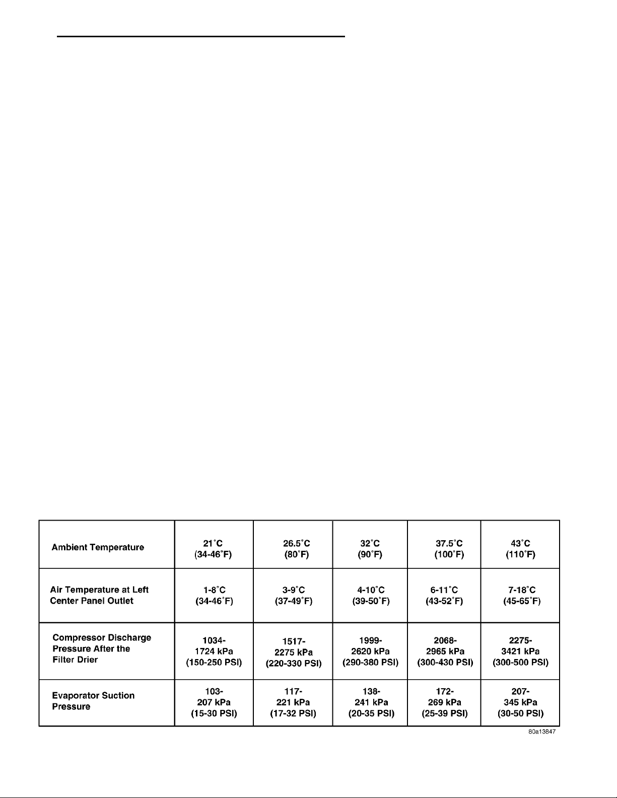
(6) With the A/C clutch engaged, compare the discharge air temperature to the A/C Performance Temperatures chart (Fig. 10).
(7) If the discharge air temperature fails to meet
the specifications in the performance temperature
chart. Refer to the Refrigerant Service Procedures for
further diagnosis.
BLOWER MOTOR ELECTRICAL DIAGNOSIS
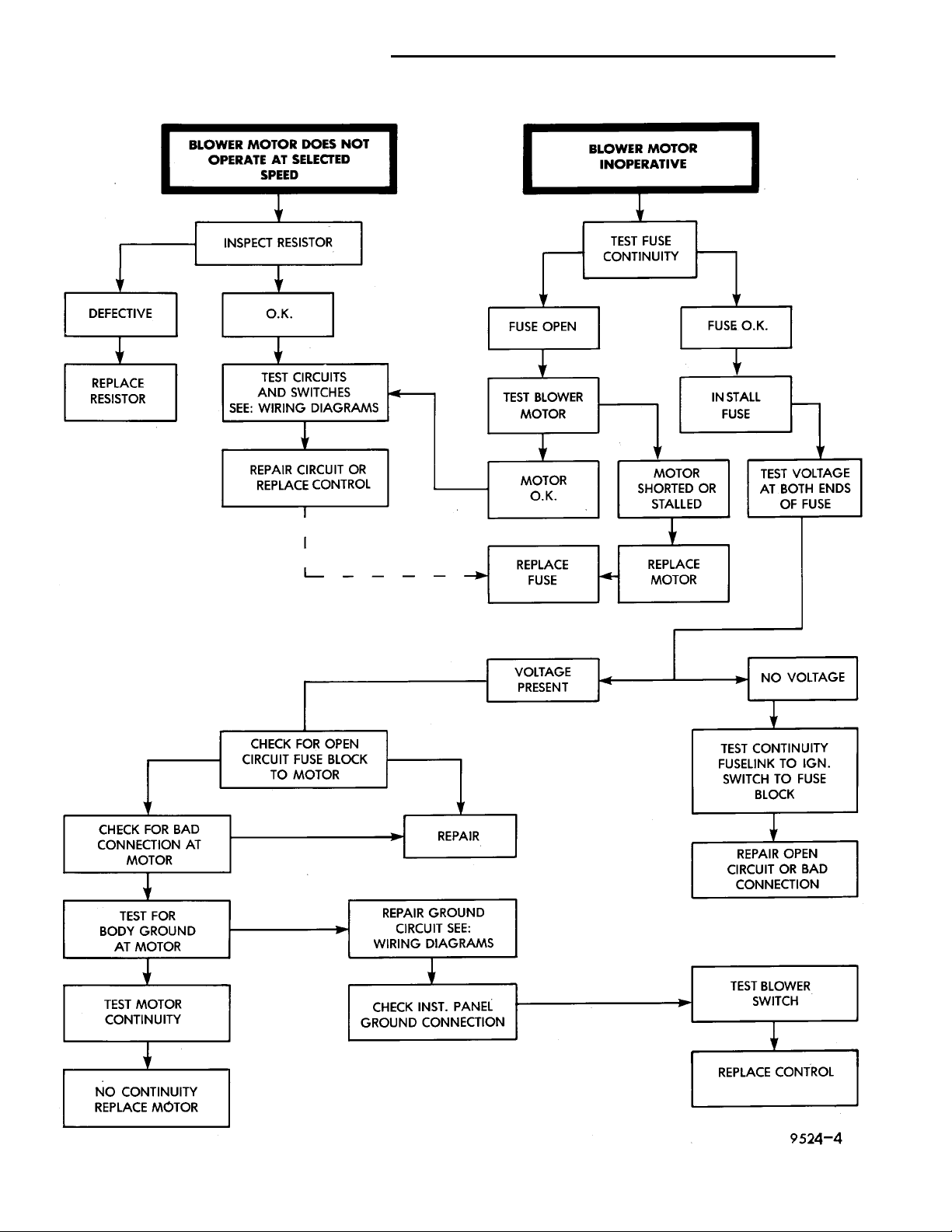
Refer to the Blower Motor Electrical System Diagnosis chart (Fig. 11) in this section. Also refer to
Group 8W, Wiring Diagrams for more information.
BLOWER MOTOR VIBRATION AND/OR NOISE DIAGNOSIS
The resistor block supplies the blower motor with
varied voltage (low and middle speeds) or battery
voltage (high speed).
CAUTION: Stay clear of the blower motor and resistor block (Hot). Do not operate the blower motor
with the resistor block removed from the heater-A/C
housing.
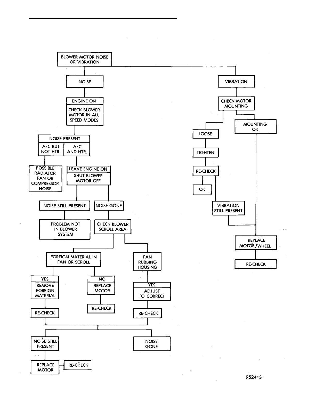
Refer to the Blower Motor Vibration/Noise chart
(Fig. 12) for diagnosis.
COMPRESSOR NOISE DIAGNOSIS
Excessive noise while the A/C is being used, can be
caused by loose mounts, loose clutch, or high operating pressure. Verify compressor drive belt condition,
proper refrigerant charge and head pressure before
compressor repair is performed.
If the A/C drive belt slips at initial start-up, it does
not necessarily mean the compressor has failed.
With the close tolerances of a compressor it is possible to experience a temporary lockup. The longer
the A/C system is inactive, the more likely the condition to occur.
This condition is the result of normal refrigerant
movement within the A/C system caused by temperature changes. The refrigerant movement may wash
the oil out of the compressor.
Fig. 10 A/C PERFORMANCE TEMPERATURES
Page 8
BLOWER MOTOR DOES NOTOPERATE AT SELECTED SPEEDINSPECT RESISTORDEFECTIVE O.K.REPLACE RESIS-TOR TEST CIRCUITS ANDSWITCHES SEE: WIRINGDIAGRAMSREPAIR CIRCUIT ORREPLACE CONTROL BLOWER MOTOR INOPERATIVETEST FUSE CONTI-NUITYFUSE OPENFUSE O.K.TEST BLOWER MOTORINSTALL FUSEMOTOR O.K.MOTOR SHORTED ORSTALLEDTEST VOLTAGE AT BOTHENDS OF FUSEREPLACE FUSEREPLACE MOTORVOLTAGE PRESENTNO VOLTAGETEST CONTINUITYFUSELINK TO IGN. SWITCHTO FUSE BLOCKREPAIR OPEN CIRCUIT ORBAD CONNECTIONTEST BLOWER SWITCHREPLACE CONTROLNO CONTINUITY REPLACEMOTORTEST MOTOR CONTINUITYCHECK INST. PANELGROUND CONNECTIONTEST FOR BODY GROUNDAT MOTORREPAIR GROUND CIRCUITSEE: WIRING DIAGRAMSCHECK FOR BAD CONNEC-TION AT MOTORREPAIRCHECK FOR OPEN CIRCUITFUSE BLOCK TO MOTOR
24 - 8 HEATING AND AIR CONDITIONING PL
DIAGNOSIS AND TESTING (Continued)
Fig. 11 Blower Motor Electrical Diagnosis
Page 9
BLOWER MOTOR NOISE ORVIBRATIONNOISE
NOISE PRESENT
A/C AND HTR.POSSIBLE RADIA-TOR FAN ORCOMPRESSORNOISE
NOISE STILL PRESENTNOISE GONEPROBLEM NOT IN BLOWERSYSTEMCHECK BLOWER SCROLLAREAFOREIGN MATERIAL IN FANOR SCROLLFAN RUBBING HOUSINGYESREMOVE FOREIGN MATE-RIALNOREPLACE MOTORYESADJUST TO CORRECTRE-CHECKRE-CHECKRE-CHECKNOISE STILL PRESENTREPLACE MOTORRE-CHECKNOISE GONEVIBRATIONCHECK MOTOR MOUNTINGMOUNTING OKLOOSETIGHTENRE-CHECKOKVIBRATION STILL PRESENTREPLACE MOTOR/WHEELRE-CHECK
A/C BUT NOT
PL HEATING AND AIR CONDITIONING 24 - 9
HTR.
CHECK BLOWER
MOTOR IN ALL SPEED
DIAGNOSIS AND TESTING (Continued)
ENGINE ON
LEAVE ENGINE ON
SHUT BLOWER MOTOR OFF
MODES
Fig. 12 Blower Motor Noise/Vibration Diagnosis
Page 10
EXPANSION VALVELOW PRESSURE CUT OFFSWITCHSUCTION LINECONTROL HEAD
24 - 10 HEATING AND AIR CONDITIONING PL
DIAGNOSIS AND TESTING (Continued)
EXPANSION VALVE
NOTE: Expansion valve tests should be performed
after compressor tests.
Liquid CO2 is required to test the expansion
valve. It is available from most welding supply facilities. CO2 is also available from companies which
service and sell fire extinguishers.
Review Safety Precautions and Warnings in the
General Information section of this Group. The work
area and vehicle must be 21° to 27°C (70° to 85°F)
when testing expansion valve. To test the expansion
valve:
(1) Connect a charging station or manifold gauge
set to the refrigerant system service ports.
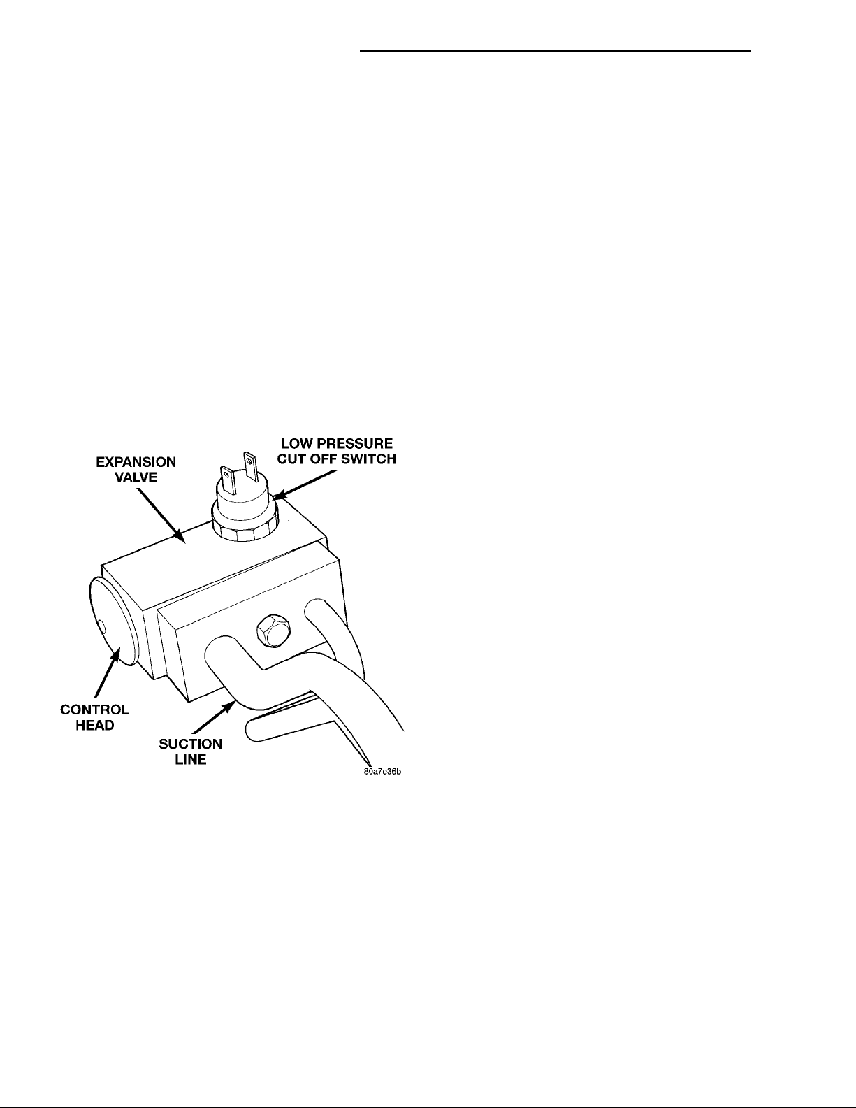
(2) Disconnect wire connector at low pressure cutoff switch (Fig. 13). Using a jumper wire, jump terminals inside wire connector boot.
Fig. 13 Low Pressure Cut-Off Switch
(3) Close all doors, windows and vents to the passenger compartment.
(4) Set Heater-A/C control to A/C, full heat, floor,
RECIRC. and high blower.
(5) Start the engine and hold the idle speed (1000
rpm). After the engine has reached running temperature, allow the passenger compartment to heat up.
This will create the need for maximum refrigerant
flow into the evaporator.
(6) If the refrigerant charge is sufficient, discharge
(high pressure) gauge should read 965 to 2620 kPa
(140 to 380 psi). Suction (low pressure) gauge should
read 103 to 2417 kPa (15 to 35 psi). If system cannot
achieve proper pressure readings, replace the expansion valve. If pressure is correct, proceed with test.
WARNING: PROTECT SKIN AND EYES FROM CONTACTING CO2 PERSONAL INJURY CAN RESULT.
(7) If suction side low pressure is within specified
range, freeze the expansion valve control head (Fig.
13) for 30 seconds. Use a super cold substance (liquid
CO2). Do not spray refrigerant on the expansion
valve for this test. Suction side low pressure should
drop to 34.5 kPa (5 psi) If not, replace expansion
valve.
(8) Allow expansion valve to thaw. The low pressure gauge reading should stabilize at 103 to 241
kPa (15 to 35 psi). If not, replace expansion valve.
(9) When expansion valve test is complete, test
A/C overall performance. Refer to the Heater and A/C
Performance Test in this section. Remove all test
equipment before returning vehicle to use.
EVAPORATOR PROBE TEST
The work area and vehicle must be between 16° C
(60° F) and 32° C (90° F) when testing the switch.
(1) Disconnect the three wire connector from the
evaporator probe lead located behind the glove box.
(2) Start engine and set A/C to low blower motor
speed, panel, full cool, and RECIRC.
(3) Using a voltmeter, check for battery voltage
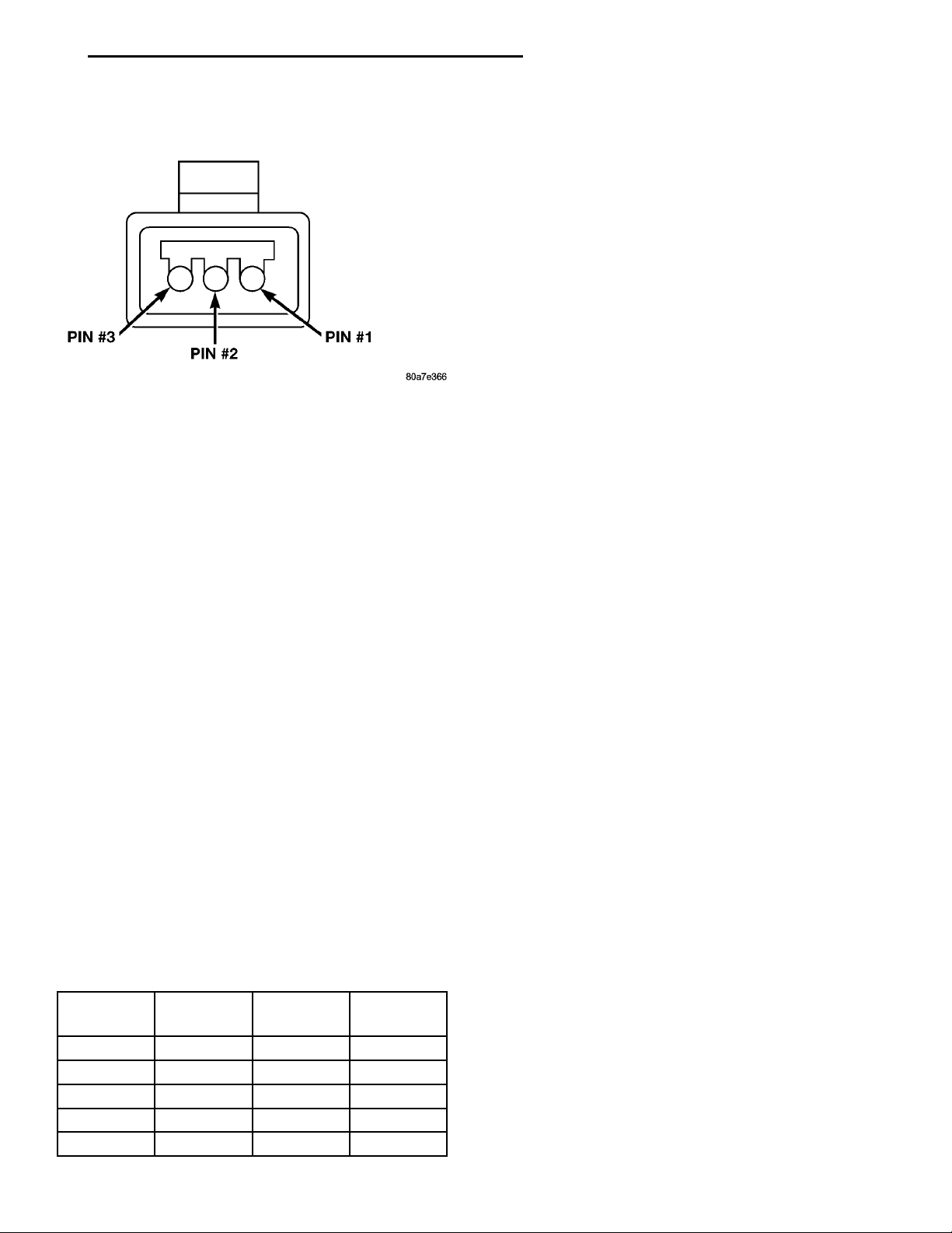
between Pin 1 and 2. If no voltage is detected, there is
no power to the switch. Check wiring and fuses. Refer
to Group 8W, Wiring Diagrams for circuit diagnosis.
(4) Using a voltmeter, check for battery voltage
between Pin 1 and Pin 3. If no voltage is detected, there
is no voltage from the Powertrain Control Module. Refer
to Group 8W, Wiring Diagrams. If voltage is OK, connect a jumper wire between Pin 1 and Pin 3. The compressor clutch should engage. If the clutch engages,
remove the jumper wire immediately and go to Step 5.
If the compressor clutch does not engage, check the
operation of the clutch and repair as necessary.
(5) If compressor clutch engages, connect the evaporator probe 3-way connector. The compressor clutch
should engage or cycle depending on evaporator temperature. If OK, go to Step 6. If not OK, replace the
clutch cycling switch.
(6) The engine running and the A/C set to:
• Blower motor on low speed
• Panel position
• Full cool
• RECIRC.
Close all doors and windows. Place a thermometer
in the center discharge vent.
(7) If the clutch does not begin to cycle off between
2° C to 7° C (35° F to 45° F), verify that the evaporator probe is fully installed and not loose in evaporator. If it is not properly installed, install probe and
Page 11
PIN #3PIN #2PIN #1
PL HEATING AND AIR CONDITIONING 24 - 11
DIAGNOSIS AND TESTING (Continued)
retest outlet temperature. If the evaporator probe is
properly installed, replace the clutch cycling switch.
Fig. 14 Evaporator Probe Harness Connector
HEATER PERFORMANCE TEST
PRE-DIAGNOSTIC PREPARATIONS
Review Safety Precautions and Warnings in this
group before performing the following procedures.
Check the coolant level, drive belt tension, vacuum
line connections, radiator air flow and fan operation.
Start engine and allow to warm up to normal temperature.
WARNING: DO NOT REMOVE RADIATOR CAP
WHEN ENGINE IS HOT, PERSONAL INJURY CAN
RESULT.
If vehicle has been run recently, wait 15 minutes
before removing cap. Place a rag over the cap and
turn it to the first safety stop. Allow pressure to
escape through the overflow tube. When the system
stabilizes, remove the cap completely.
MAXIMUM HEATER OUTPUT: TEST AND ACTION
Engine coolant is provided to the heater system by
two 16 mm (5/8 inch inside diameter) heater hoses.
With engine idling at normal running temperature,
set the control to maximum heat, floor, and high
blower setting. Using a test thermometer, check the
air temperature coming from the floor outlets, refer
to Temperature Reference chart.
TEMPERATURE REFERENCE CHART
Ambient Temp.
Celsius Fahrenheit Celsius Fahrenheit
15.5° 60° 62.2° 144°
21.1° 70° 63.8° 147°
26.6° 80° 65.5° 150°
32.2° 90° 67.2° 153°
Minimum
Floor
Outlet
Temp.
If the floor outlet air temperature is insufficient,
refer to Group 7, Cooling Systems for specifications.
Both heater hoses should be HOT to the touch (coolant return hose should be slightly cooler than the
supply hose). If coolant return hose is much cooler
than the supply hose, locate and repair engine coolant flow obstruction in heater system.
POSSIBLE LOCATIONS OR CAUSE OF OBSTRUCTED COOLANT FLOW
(1) Pinched or kinked heater hoses.
(2) Improper heater hose routing.
(3) Plugged heater hoses or supply and return
ports at cooling system connections, refer to Group 7,
Cooling System.
(4) Plugged heater core.
(5) Air locked heater core.
(6) If coolant flow is verified and outlet temperature is insufficient, a mechanical problem may exist.
POSSIBLE LOCATION OR CAUSE OF
INSUFFICIENT HEAT
(1) Obstructed cowl air intake.
(2) Obstructed heater system outlets.
(3) Blend-air door not functioning properly.
TEMPERATURE CONTROL
If temperature cannot be adjusted with the TEMP
lever on the control panel, the following could require
service:
(1) Blend-air door binding.
(2) Faulty blend-air door cable.
(3) Improper engine coolant temperature.
(4) Faulty Instrument Panel Control.
LOW PRESSURE CUT-OFF SWITCH
The work area must not be below 21°C (70°F) to
test the compressor clutch circuit.
(1) With gear selector in park or neutral and park
brake set, start engine and allow to idle.
(2) Raise hood and disconnect low pressure cut off
switch connector boot.
(3) Using a suitable jumper wire, jump across the
terminals inside wire connector boot.
(4) If the compressor clutch does not engage, the
cycling clutch switch, wiring, relay, or fuse can be
defective. Refer to Group 8W, Wiring Diagrams.
(5) If clutch engages, connect manifold gauge set.
Read low pressure gauge. At pressure above 97 kPa
(14 psi) and above, low pressure out off switch will
complete the clutch circuit. If the low pressure gauge
reads below 140 kPa (20 psi), the system is low on
refrigerant charge or empty due to a leak. Refer to
Service–Procedures, System Leak Checking in this
section.
Page 12
DEG. F200°180°160°140°120°100°80°60°40° LIQUID LINE TEMPERATURE
24 - 12 HEATING AND AIR CONDITIONING PL
UNDERCHARGED
ANYTHING IN
THIS SHADED
AREA
PROPER CHARGE RANGEOVERCHARGEDANYTHING IN THIS SHADED AREA50 P.S.I.100 P.S.I.150 P.S.I.200 P.S.I.250 P.S.I.300 P.S.I.350 P.S.I.400 P.S.I.450 P.S.I.500 P.S.I.LIQUID LINE PRESSURE
DIAGNOSIS AND TESTING (Continued)
(6) Install connector boot on switch and repeat
Step 3. If the clutch does not engage, replace the low
pressure cut off switch.
SYSTEM CHARGE LEVEL TEST
The procedure below should be used to check
and/or fill the refrigerant charge in the air conditioning system.
WARNING: AVOID BREATHING A/C REFRIGERANT
AND LUBRICANT VAPOR OR MIST. EXPOSURE MAY
IRRITATE EYES, NOSE AND THROAT. USE ONLY
APPROVED SERVICE EQUIPMENT MEETING SAE
REQUIREMENTS TO DISCHARGE R-134a SYSTEM.
IF ACCIDENTAL SYSTEM DISCHARGE OCCURS,
VENTILATE WORK AREA BEFORE RESUMING SERVICE.
R-134a SERVICE EQUIPMENT OR VEHICLE A/C
SYSTEM SHOULD NOT BE PRESSURE TESTED OR
LEAK TESTED WITH COMPRESSED AIR. MIXTURE
OF AIR and R-134a CAN BE COMBUSTIBLE AT ELEVATED PRESSURES. THESE MIXTURES ARE
POTENTIALLY DANGEROUS AND MAY RESULT IN
FIRE OR EXPLOSION CAUSING INJURY OR PROPERTY DAMAGE.
NOTE: The maximum amount of R-134a refrigerant
that the air conditioning system holds is 784 grams
(28 oz. or 1.57 lbs.)
It is recommended to use the gauges or reclaim/re-
cycle equipment.
(1) Use a manifold gauge and check the liquid line
pressure.
(2) Attach a clamp-on thermocouple (P.S.E. 66-3240014 or 80PK-1A) or equivalent to the liquid line
near the filter/drier.
(3) The vehicle must be in the following modes:
• Automatic transaxle in park or manual tran-
saxle in neutral.
• Engine at idle
• A/C controls set to outside air
• Panel mode
• A/C ON full cool
• Blower motor ON high speed
• Vehicle windows closed
(4) Operate system for a couple of minutes to allow
the system to stabilize.
(5) Observe filter/drier pressure and Liquid line
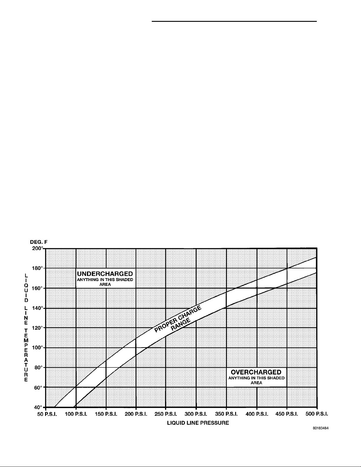
temperature. Using the Charge Determination Chart
(Fig. 15) determine where the system is currently
operating. If the system is not in the proper range,
reclaim all the refrigerant and recharge per A/C
label.
Fig. 15 Charge Determination Chart
Page 13
PL HEATING AND AIR CONDITIONING 24 - 13
DIAGNOSIS AND TESTING (Continued)
VACUUM CONTROL SYSTEM
Use an adjustable vacuum test set (Special Tool
C-3707) and a suitable vacuum pump to test the
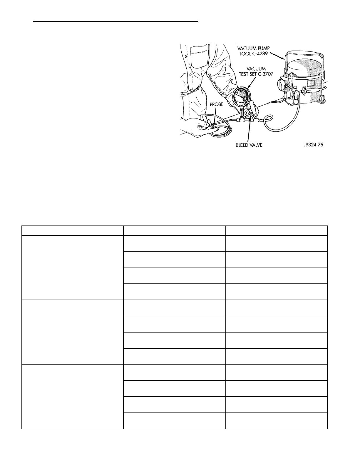
heater-A/C vacuum control system. With a finger
placed over the end of the vacuum test hose probe
(Fig. 16), adjust the bleed valve on the test set gauge
to obtain a vacuum of exactly 27 kPa (8 in. Hg.).
Release and block the end of the probe several times
to verify that the vacuum reading returns to the
exact 27 kPa (8 in. Hg.) setting. Otherwise, a false
reading will be obtained during testing.
ONE-WAY CHECK VALVE
(1) Disconnect the heater-A/C vacuum supply
(Black) tube in the engine compartment. This tube
passes through an opening in the dash panel.
(2) Remove the one-way vacuum check valve. The
valve is located on the (Black) vacuum supply hose at
the brake power booster.
(3) Connect the test set vacuum supply hose to the
heater side of the valve. When connected to this side
of the check valve, no vacuum should pass and the
test set gauge should return to the 27 kPa (8 in. Hg.)
setting. If OK, go to step Step 4. If not OK, replace
the faulty valve.
engine vacuum side of the valve. When connected to
this side of the check valve, vacuum should flow
through the valve without restriction. If not OK,
replace the faulty valve.
Fig. 16 Adjust Vacuum Test Bleed Valve
(4) Connect the test set vacuum supply hose to the
CONDITION POSSIBLE CAUSES CORRECTION
NO FORCED AIR IN HEAT
POSITION
NO FORCED AIR IN PANEL
POSITION
NO FORCED AIR IN DEFROST
POSITION
1. Vacuum line pinched or leaking. 1. Locate and repair vacuum leak or
pinched line.
2. Faulty heat defroster or mode
door.
3. Faulty selector switch. 3. Test selector switch and replace if
4. Vacuum check valve. 4. Test check valve and replace if
1. Vacuum line pinched or leaking. 1. Locate and repair vacuum leak or
2. Faulty mode door. 2. Test actuator and door operation.
3. Faulty selector switch. 3. Test selector switch and replace if
4. Vacuum check valve. 4. Test check valve and replace if
1. Vacuum line pinched or leaking. 1. Locate and repair vacuum leak or
2. Faulty heat defroster or mode
door.
3. Faulty selector switch. 3. Test selector switch and replace if
4. Vacuum check valve. 4. Test check valve and replace if
2. Test actuators and door
operation. Repair as necessary.
necessary.
necessary.
pinched line.
Repair as necessary.
necessary.
necessary.
pinched line.
2. Test actuators and door
operation. Repair as necessary.
necessary.
necessary.
Heater-A/C Vacuum System Diagnosis
Page 14

24 - 14 HEATING AND AIR CONDITIONING PL
DIAGNOSIS AND TESTING (Continued)
HEATER-A/C CONTROLS
The operation of the Circulation door can be
viewed by removing the blower motor and looking up
into the unit inlet. See Blower Motor Wheel and
Assembly removal and installation in this section for
service procedures.
(1) Connect the test set vacuum probe to the heater-A/C vacuum supply (Black) hose in the engine
compartment. Position the test set gauge so that it
can be viewed from the passenger compartment.
(2) Start with the Mode control in the Panel position and the Circulation control in the Ouside-air
position.
(3) Move the Circulation control to the Recirculation position (the Circulation door should move into
the Recirculation position). After a short pause move
the Mode control to the Defrost position (the Circulation door should move to the Outside-air position).
The test gauge should return to the calibrated setting of 27 kPa (8in. Hg.) after each selection is made.
If the gauge cannot achieve the calibrated setting,
the vacuum circuit or a component has a leak.
(4) If the gauge achieves the calibrated setting but
the door does not move, there is either a pinched vacuum line or a failed actuator.
LOCATING VACUUM LEAKS
(1) Connect the test vacuum probe to the vehicles
(Black) supply hose. Position the vacuum test gauge
so it can be viewed from the passenger compartment.
(2) Place the Mode in the Panel position and the
Circulation control in the Recirculation position.
(3) Remove the instrument panel top cover.
(4) Remove the right side upper instrument panel
bezel
(5) Remove the center vent duct.
(6) Remove and block the Supply (Black) vacuum
line at the control. The test gauge should return to
the calibrated setting of 27 kPa (8 in. Hg). If not,
there is a leak in the Supply line.
(7) If there is no leak in the Supply line, reconnect
it to the Control and remove the Actuator Feed (Red)
line from the Control. Block the vacuum connection
on the Control from where the line was removed. The
test gauge should return to the calibrated setting of
27 kPa (8 in. Hg.). If not, there is a leak in the Control.
(8) If there is no leak in the Supply line or the
Control, reconnect the Actuator Feed (Red) line to the
control. Remove and block the Actuator Feed (Red)
line at the Actuator. The test gauge should return to
the calibrated setting of 27 kPa (8 in. Hg.). If not
there is a leak in the Actuator Feed line.
(9) If there is no leak in the Supply line, Control,
or the Actuator Feed line, the leak must be in the
Actuator itself. Connect the Vacuum hose from the
Vacuum Test Gauge directly to the Actuator to verify
the leak. The Actuator vacuum port is accessible
behind and above the Glove Box.
LOCATING PINCHED VACUUM LINES
The operation of the Circulation door can be
viewed by removing the blower motor and looking up
into the unit inlet. See Blower Motor Wheel and
Assembly removal and installation in this section for
service procedures.
(1) Connect the test vacuum probe to the vehicles
(Black) supply hose. Position the vacuum test gauge
so it can be viewed from the passenger compartment.
(2) Place the Mode in the Panel position and the
Circulation control in the Recirculation position.
(3) Remove the right instrument panel top cover.
(4) Remove the right side upper instrument panel
bezel.
(5) Remove the center vent duct.
(6) Remove the Supply (Black) vacuum line at the
control. The test gauge should drop indicating free
flow through the Supply line. If not, there is a blockage in the Supply line.
(7) If there is no blockage in the Supply line,
reconnect it to the Control. Remove the Actuator
Feed (Red) line from the Control. The test gauge
should drop indicating free flow through the Supply
line and Control. If not the vacuum switches on the
Control are not functioning.
(8) If there is no blockage in the Supply line or the
Control, reconnect the Actuator Feed (Red) line to the
control. Remove the Actuator Feed (Red) line at the
Actuator. The Actuator vacuum port is accessible
behind and above the Glove Box. The test guage
should drop indicating free flow through the supply
line, Control, and the Actuator Feed line. If not,
there is a blockage in the Actuator Feed line.
(9) If there is no blockage in the Supply line, Control, or the Actuator Feed line, the Actuator must
have failed. Connect the Vacuum hose from the Vacuum Test Gauge directly to the Actuator to verify the
Actuator has failed.
SERVICE PROCEDURES
CHARGING A/C SYSTEM
PARTIAL CHARGE
This vehicle does not have a sight glass. It is not
possible to determine the amount of (R-134a) charge
in the system. Therefore it is necessary to completely
evacuate and recover the system, and then recharge
the system fully.
EVACUATION
Before adding refrigerant, all air must be evacuated from the system.
Page 15
A/C SERVICE PORTSFILTER/DRIER
PL HEATING AND AIR CONDITIONING 24 - 15
SERVICE PROCEDURES (Continued)
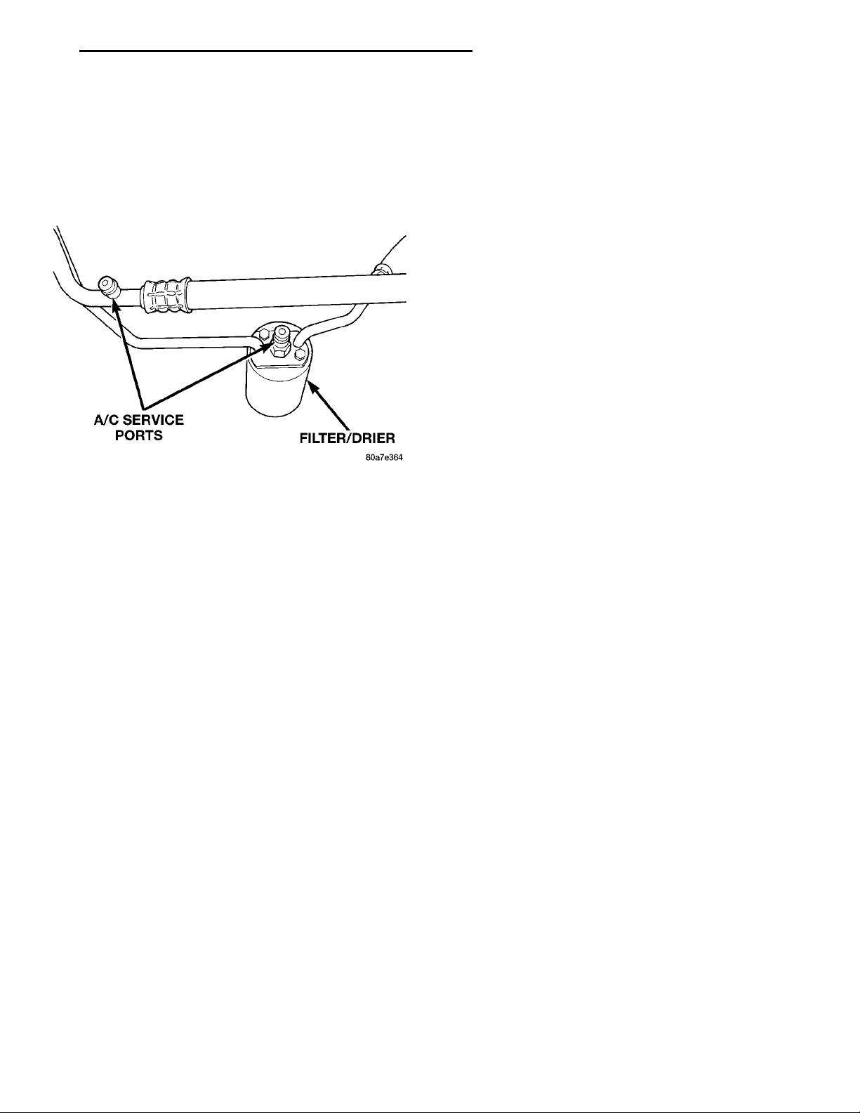
• Connect a manifold gauge set to the A/C service
ports (Fig. 17).
• Use a vacuum pump or charging station and
evacuate system to 95 kPa (28 inches Hg) for 30 minutes.
• Go to Charging A/C System below.
Fig. 17 A/C Service Ports
CHARGING A/C SYSTEM
The procedure below should be used to fill the
refrigerant charge in the air conditioning system.
This A/C system does not have or use a sight glass to
check or charge the system.
WARNING: REVIEW SAFETY PRECAUTIONS AND
WARNINGS IN THIS GROUP BEFORE CHARGING
THE REFRIGERANT SYSTEM.
AVOID BREATHING A/C REFRIGERANT AND LUBRICANT VAPOR OR MIST. EXPOSURE MAY IRRITATE
EYES, NOSE AND THROAT. USE ONLY APPROVED
SERVICE EQUIPMENT MEETING SAE REQUIREMENTS
TO DISCHARGE R-134a SYSTEM. IF ACCIDENTAL
SYSTEM DISCHARGE OCCURS, VENTILATE WORK
AREA BEFORE RESUMING SERVICE.
R-134a SERVICE EQUIPMENT OR VEHICLE A/C SYSTEM SHOULD NOT BE PRESSURE TESTED OR LEAK
TESTED WITH COMPRESSED AIR. MIXTURE OF AIR
and R-134a CAN BE COMBUSTIBLE AT ELEVATED
PRESSURES. THESE MIXTURES ARE POTENTIALLY
DANGEROUS AND MAY RESULT IN FIRE OR EXPLOSION CAUSING INJURY OR PROPERTY DAMAGE.
(1) If using a separate vacuum pump close all
valves before disconnecting pump. Connect manifold
gauge set to the A/C service ports (Fig. 17).
NOTE: The air conditioning system in this vehicle
holds 784 grams (28 oz. or 1.57 lbs.) of R-134a
refrigerant.
(2) Measure refrigerant (refer to capacities). Refer
to the instructions provided with the equipment
being used.
(3) Verify engine is shut off. Open the suction and
discharge valves. Open the charge valve to allow the
refrigerant to flow into the system. When the transfer of refrigerant has stopped, close the suction and
discharge valve.
(4) If all of the charge did not transfer from the
dispensing device, put vehicle controls into the following mode:
• Automatic transaxle in park or manual tran-
saxle in neutral
• Engine idling at 700 rpm
• A/C control set in 100 percent outside air
• Panel mode
• Blower motor ON high speed
• Vehicle windows closed
If the A/C compressor does not engage, test the
compressor clutch control circuit and correct any failure. Refer to Group 8W, Wiring Diagrams.
(5) Open the suction valve to allow the remaining
refrigerant to transfer to the system.
WARNING: TAKE CARE NOT TO OPEN THE DISCHARGE (HIGH-PRESSURE) VALVE AT THIS TIME.
(6) Close all valves and test the A/C system performance.
(7) Disconnect the charging station or manifold
gauge set. Install the service port caps.
EVACUATING REFRIGERANT SYSTEM
NOTE: Special effort must be used to prevent moisture from entering the A/C system oil. Moisture in
the oil is very difficult to remove and will cause a
reliability problem with the compressor.
CAUTION: Do not overcharge refrigerant system,
as excessive compressor head pressure can cause
noise and system failure.
After the system has been tested for leaks and
evacuated, a refrigerant (R-134a) charge can be
injected into the system.
NOTE: When connecting the service equipment
coupling to the line fitting, verify that the valve of
the coupling is fully closed. This will reduce the
amount of effort required to make the connection.
If a compressor designed to use R-134a refrigerant
is left open to the atmosphere for an extended period
of time. It is recommended that the refrigerant oil be
drained and replaced with new oil or a new compressor be used. This will eliminate the possibility of contaminating the refrigerant system.
If the refrigerant system has been open to the
atmosphere, it must be evacuated before the system
can be filled. Moisture and air mixed with the refrigerant will raise the compressor head pressure above
acceptable operating levels. This will reduce the per-
Page 16
LOW SIDE CONNECTORHIGH SIDE CONNECTORTO MANIFOLD SET
R-134 REFRIGERANTRECOVERY MACHINE
24 - 16 HEATING AND AIR CONDITIONING PL
SERVICE PROCEDURES (Continued)
formance of the air conditioner and damage the compressor. Moisture will boil at near room temperature
when exposed to vacuum. To evacuate the refrigerant
system:
NOTE: When connecting the service equipment
coupling to the line fitting, verify that the valve of
the coupling is fully closed. This will reduce the
amount of effort required to make the connection.
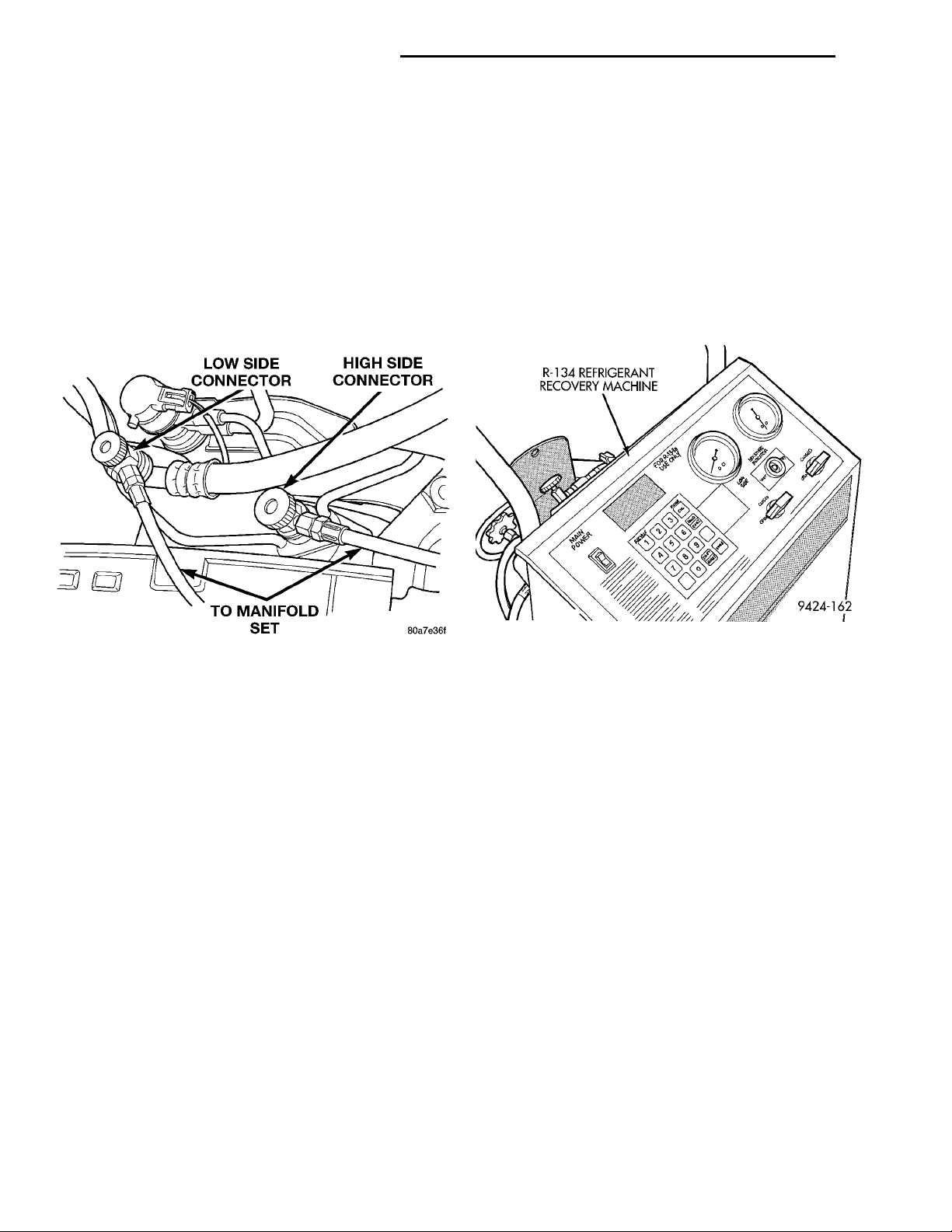
(1) Connect a suitable charging station, refrigerant
recovery machine, and a manifold gauge set with
vacuum pump (Fig. 18).
poor performance. Never add any other type of
refrigerant to a system designed to use R-134a
refrigerant. System failure will occur.
The high pressure service port is located on the
ffilter/drier. The low pressure service port is located
on the suction line near the strut tower.
When servicing a system, it is required that an air
conditioning charging recovery/recycling machine be
used (Fig. 19). Contact an automotive service equipment supplier for proper equipment. Refer to the
operating instructions provided with the equipment
for proper operation.
Fig. 18 Refrigerant Recovery Machine Hookup
(2) Open the suction and discharge valves and
start the vacuum pump. The vacuum pump should
run a minimum of 45 minutes prior to charge to
eliminate all moisture in system. When the suction
gauge reads -88 kPa (- 26 in. Hg) vacuum or greater
for 45 minutes, close all valves and turn off vacuum
pump. If the system fails to reach specified vacuum,
the refrigerant system likely has a leak that must be
corrected. If the refrigerant system maintains specified vacuum for at least 30 minutes, start the vacuum pump, open the suction and discharge valves.
Then allow the system to evacuate an additional 10
minutes.
(3) Close all valves. Turn off and disconnect the
vacuum pump.
(4) The refrigerant system is prepared to be
charged with refrigerant.
R-134a REFRIGERANT
This vehicle uses a new type of refrigerant called
R-134a. It is a non-toxic, non-flammable, clear colorless liquefied gas.
R-134a refrigerant is not compatible with R-12
refrigerant in an air conditioning system. Even a
small amount of R-12 in a R-134a system could cause
compressor failure, refrigerant oil to sludge and/or
Fig. 19 Refrigerant Recovery/Recycling Station
(Typical)
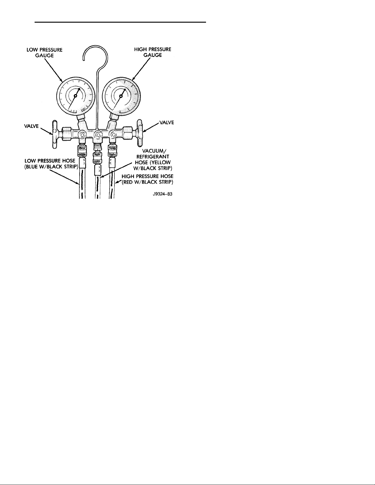
A manifold gauge set (Fig. 20) must also be used in
conjunction with the charging and/or recovery/recycling device. Only use gauges that have not been
used for R-12. The service hoses on the gauge set
should have manual (turn wheel) or automatic back
flow valves at the service port connector ends. This
will prevent refrigerant R-134a from being released
into the atmosphere.
R-134a refrigerant requires a special type of compressor oil. When adding oil, make sure to use the oil
that is specified on the under hood label.
Due to the different characteristics of R-134a it
requires all new service procedures.
The use of R-134a will have a positive environmental impact due to it’s zero ozone depletion and low
global warming impact.
SERVICING REFRIGERANT OIL LEVEL
CAUTION: The refrigerant oil used in a R-134a A/C
system is unique. Use only oils which were
designed to work with R-134a refrigerant. The oil
designated for this vehicle is ND8 PAG (polyalkalene glycol).
Page 17
LOW PRESSUREGAUGE HIGH PRESSUREGAUGEVALVEVACUUM/REFRIG-ERANT HOSE (YEL-LOW W/BLACK STRIP)HIGH PRESSUREHOSE (REDW/BLACK STRIP)LOW PRESSURE HOSE(BLUE W/BLACK STRIP)VALVE
PL HEATING AND AIR CONDITIONING 24 - 17
SERVICE PROCEDURES (Continued)
TURES ARE POTENTIALLY DANGEROUS AND MAY
RESULT IN FIRE OR EXPLOSION CAUSING INJURY
OR PROPERTY DAMAGE.
AVOID BREATHING A/C REFRIGERANT AND
LUBRICANT VAPOR OR MIST. EXPOSURE MAY
IRRITATE EYES, NOSE AND THROAT. USE ONLY
APPROVED SERVICE EQUIPMENT MEETING SAE
REQUIREMENTS TO DISCHARGE R-134a SYSTEM.
IF ACCIDENTAL SYSTEM DISCHARGE OCCURS,
VENTILATE WORK AREA BEFORE RESUMING SERVICE.
If the A/C system is not cooling properly, determine
if the refrigerant system is fully charged with
R-134a. This is accomplished by performing a system
Charge Level-Check or Fill. If while performing this
test A/C liquid line pressure is less than 345 kPa (50
psi) proceed to Empty Refrigerant System Leak Test.
If liquid line pressure is greater than 345 kPa (50
psi) proceed to low refrigerant level leak test. If the
refrigerant system is empty or low in refrigerant
charge, a leak at any line fitting or component seal is
Fig. 20 Manifold Gauge Set- Typical
Recovery/recycling equipment will measure the
lubricant being removed. This is the amount of lubricant to be added back to the system. If a new compressor is being installed, drain lubricant from old
compressor, measure the amount drained and discard
old lubricant. Drain the lubricant from the new compressor into a clean container. Return the amount of
lubricant measured from the old compressor, plus the
amount reclaimed from the system back into the new
compressor.
(1) Discharge refrigerant system using recovery/recycling equipment if charge is present.
(2) Disconnect refrigerant lines from A/C compressor. Cap the open lines to prevent moisture from
entering system.
(3) Remove compressor from vehicle.
(4) From suction port on top of compressor, drain
lubricant from compressor.
(5) Add system capacity minus the capacity of
components that have not been replaced. Refer to the
Lubricant Capacity Chart. Add lubricant through the
suction port on compressor. This is not to exceed 200
ml (6.75 oz.) in total.
(6) Install compressor and connect refrigerant
lines. Then evacuate and charge refrigerant system.
SYSTEM LEAK CHECKING
WARNING: R-134a SERVICE EQUIPMENT OR VEHICLE A/C SYSTEM SHOULD NOT BE PRESSURE
TESTED OR LEAK TESTED WITH COMPRESSED
AIR. MIXTURE OF AIR and R-134a CAN BE COMBUSTIBLE AT ELEVATED PRESSURES. THESE MIX-
likely. A review of the fittings, lines and components
for oily residue is an indication of the leak location.
To detect a leak in the refrigerant system, perform
one of the following procedures as indicated by the
symptoms.
EMPTY REFRIGERANT SYSTEM LEAK TEST
(1) Evacuate the refrigerant system to the lowest
degree of vacuum possible (approx. 28 in Hg.). Determine if the system holds a vacuum for 15 minutes. If
vacuum is held, a leak is probably not present. If system will not maintain vacuum level, proceed with
this procedure.
(2) Prepare a .284 Kg. (10 oz.) refrigerant charge
to be injected into the system.
(3) Connect and dispense .284 Kg. (10 oz.) of
refrigerant into the evacuated refrigerant system.
(4) Proceed to Step 2 of Low Refrigerant Level
Leak Test.
LOW REFRIGERANT LEVEL LEAK TEST
(1) Determine if there is any (R-134a) refrigerant
in the system.
(2) Position the vehicle in a wind free work area.
This will aid in detecting small leaks.
(3) Bring the refrigerant system up to operating
temperature and pressure. This is done by allowing
the engine to run for five minutes with the system
set to the following:
• Transaxle in Park
• Engine Idling at 700 rpm
• A/C Controls Set in 100 percent outside air
• Blower switch in the high A/C position
• A/C in the ON position
• Open all windows
Page 18
BLOWERMOTOR
BLOWER MOD-ULE BLOWERMOTOR
BLOWER MOTOR WIRING
BLOWER MOTOR
RETAINING
SCREWS
24 - 18 HEATING AND AIR CONDITIONING PL
SERVICE PROCEDURES (Continued)
CAUTION: A leak detector designed for R-12 refrigerant (only) will not detect leaks in a R-134a refrigerant system.
(4) Shut off the vehicle and wait 2 to 7 minutes.
Then use an Electronic Leak Detector that is
designed to detect R-134a type refrigerant and search
for leaks. Fittings, lines, or components that appear
to be oily usually indicates a refrigerant leak. To
inspect the evaporator core for leaks, insert the leak
detector probe into the drain tube opening or a heat
duct. A R-134a dye is available to aid in leak detection, use only Chrysler approved refrigerant dye.
If a thorough leak check has been completed without indication of a leak, proceed to System Charge
Level.
REMOVAL AND INSTALLATION
A/C SERVICE PORT VALVE CORES
REMOVAL
(1) Remove the valve caps (Fig. 5) and (Fig. 6)
(2) Using a R-134a refrigerant recovery machine,
Remove the refrigerant from A/C system.
(3) Using a standard valve core tool, remove the
valve core. Be careful to prevent any dirt/debris
from entering the valve core opening or getting
on the replacement valve core.
INSTALLATION
(1) When assembling the new valve core into the
port, the core should be oiled with clean ND8 PAG
compressor oil.
CAUTION: A valve that is not fully seated can lead
to damage to the valve during evacuation and
charge. This can result in system refrigerant discharge while uncoupling the charge adapters.
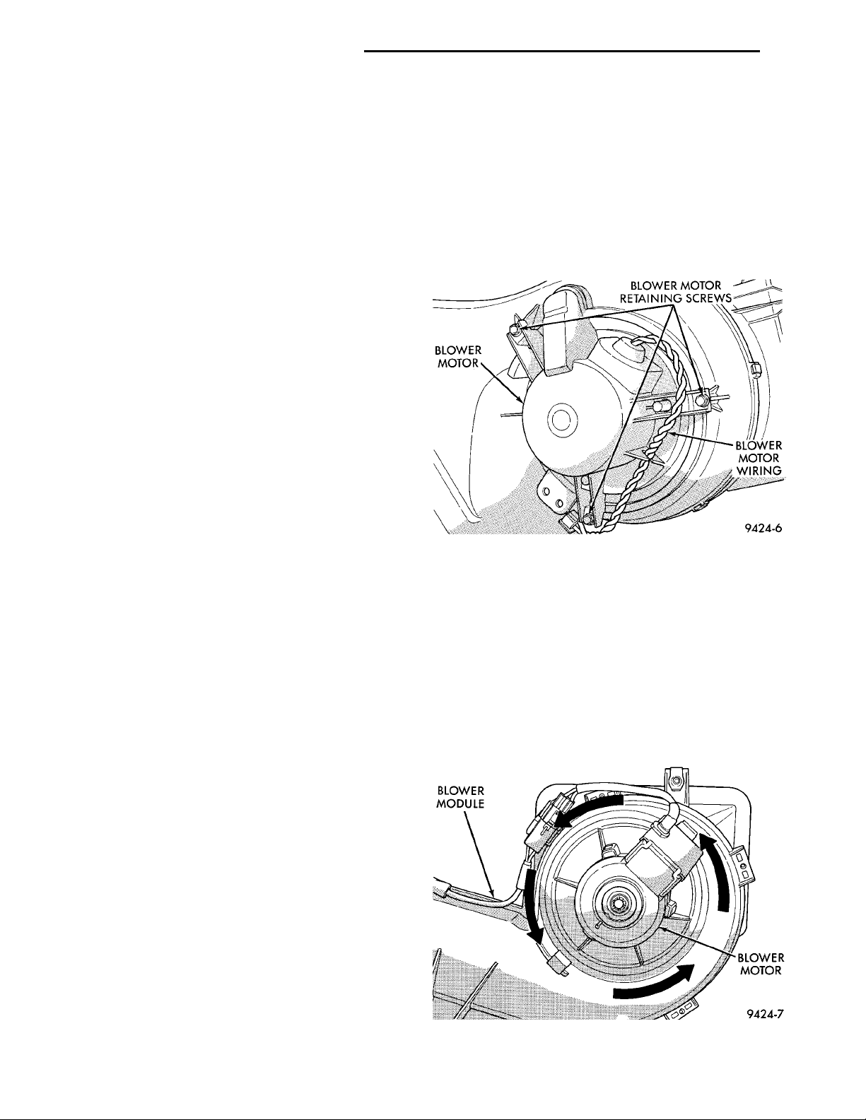
(4) Disconnect blower motor wiring connector.
(5) RHD vehicle remove the motor cover.
(6) Remove three blower motor retaining screws
(Fig. 21).
(7) Lower blower motor assembly from unit hous-
ing.
INSTALLATION
For installation, reverse the above procedures.
Then tape silencer into position.
Fig. 21 Blower Motor Retaining Screws
WITHOUT AIR CONDITIONING
REMOVAL
(1) Disconnect blower motor wiring connector.
(2) Grasp the blower motor while pulling down
tab. Turn approximately 1/8 turn counterclockwise
and remove blower motor assembly from unit housing (Fig. 22).
INSTALLATION
For installation, reverse the above procedures.
(2) Install valve core into port.
(3) Evacuate and charge the A/C system.
(4) Install the valve caps.
BLOWER MOTOR AND WHEEL ASSEMBLY
The blower motor is located on the bottom right
side of the unit housing. The blower motor can be
removed from the vehicle without having to remove
the unit housing assembly.
WITH AIR CONDITIONING
REMOVAL
(1) Remove right side scuff plate.
(2) Pull back carpet.
(3) Cut wheel housing silencer in line with blower
motor wiring.
Fig. 22 Blower Motor Removal
Page 19
PL HEATING AND AIR CONDITIONING 24 - 19
REMOVAL AND INSTALLATION (Continued)
BLOWER MOTOR RESISTOR
CAUTION: Stay clear of the blower motor and resistor block (Hot). Do not operate the blower motor
with the resistor block removed.
REMOVAL
(1) Remove windshield wipers.
(2) Remove cowl top screen.
(3) Disconnect the resistor block wiring connector.
(4) Remove two resistor block retaining screws.
The screw threads attaching the resistor block are
not full length. It is necessary to gently pry out the
resistor block while turning the screws counterclockwise enabling the threads to engages.
(5) Remove resistor block from vehicle.
INSTALLATION
For installation, reverse the above procedures.
BLOWER MOTOR WHEEL
The blower motor wheel is only serviced with the
blower motor. The wheel and the motor are balanced
as an assembly. If the blower motor wheel requires
replacement, the blower motor must also be replaced.
Refer to blower motor for replacement procedure.
(3) Using a R-134a refrigerant recovery machine,
COMPRESSOR SHAFT BOLTCOMPRESSOR CLUTCHPLATE
remove the refrigerant from A/C system. If the compressor is being replaced.
(4) Disconnect compressor clutch wire lead.
(5) Remove refrigerant lines from compressor, if
necessary.
(6) If system is left open place plug/cap over open
lines.
(7) Remove compressor attaching bolt.
(8) Remove compressor. If refrigerant lines were
not removed, lift compressor/clutch assembly and tie
it to a suitable component.
INSTALLATION
For installation, reverse the above procedures.
COMPRESSOR CLUTCH/COIL ASSEMBLY
Compressor assembly must be removed from
mounting. Although, refrigerant discharge is not necessary.
REMOVAL
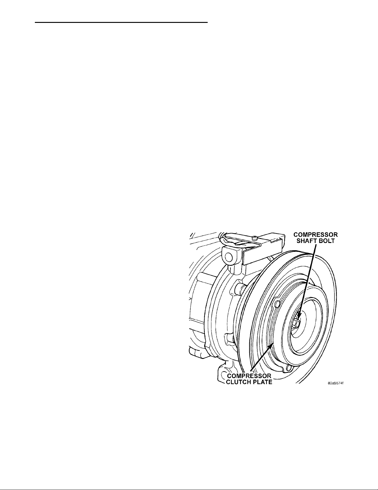
(1) Remove the compressor shaft bolt (Fig. 23). A
band type oil filter removal tool can be placed around
the clutch plate to aid in bolt removal.
COMPRESSOR
CAUTION: Add only new lubricant when system
requires additional lubricant. Do not use old
reclaimed lubricant.
REMOVAL
The A/C compressor may be unbolted and repositioned without discharging the refrigerant system.
Discharging is not necessary if removing the compressor clutch/coil assembly, engine, cylinder head, or
alternator.
WARNING: REFRIGERANT PRESSURES REMAIN
HIGH EVEN THOUGH THE ENGINE MAY BE
TURNED OFF. DO NOT TWIST OR KINK THE
REFRIGERANT LINES WHEN REMOVING A FULLY
CHARGED COMPRESSOR. SAFETY GLASSES
MUST BE WORN.
(1) Disconnect battery negative cable.
(2) Loosen and remove drive belts, refer to Group
7, Engine Cooling.
Fig. 23 Compressor Shaft Bolt and Clutch Plate
Page 20
SNAP RING PLIERSCLUTCH COILCOMPRESSORSNAP RING
24 - 20 HEATING AND AIR CONDITIONING PL
REMOVAL AND INSTALLATION (Continued)
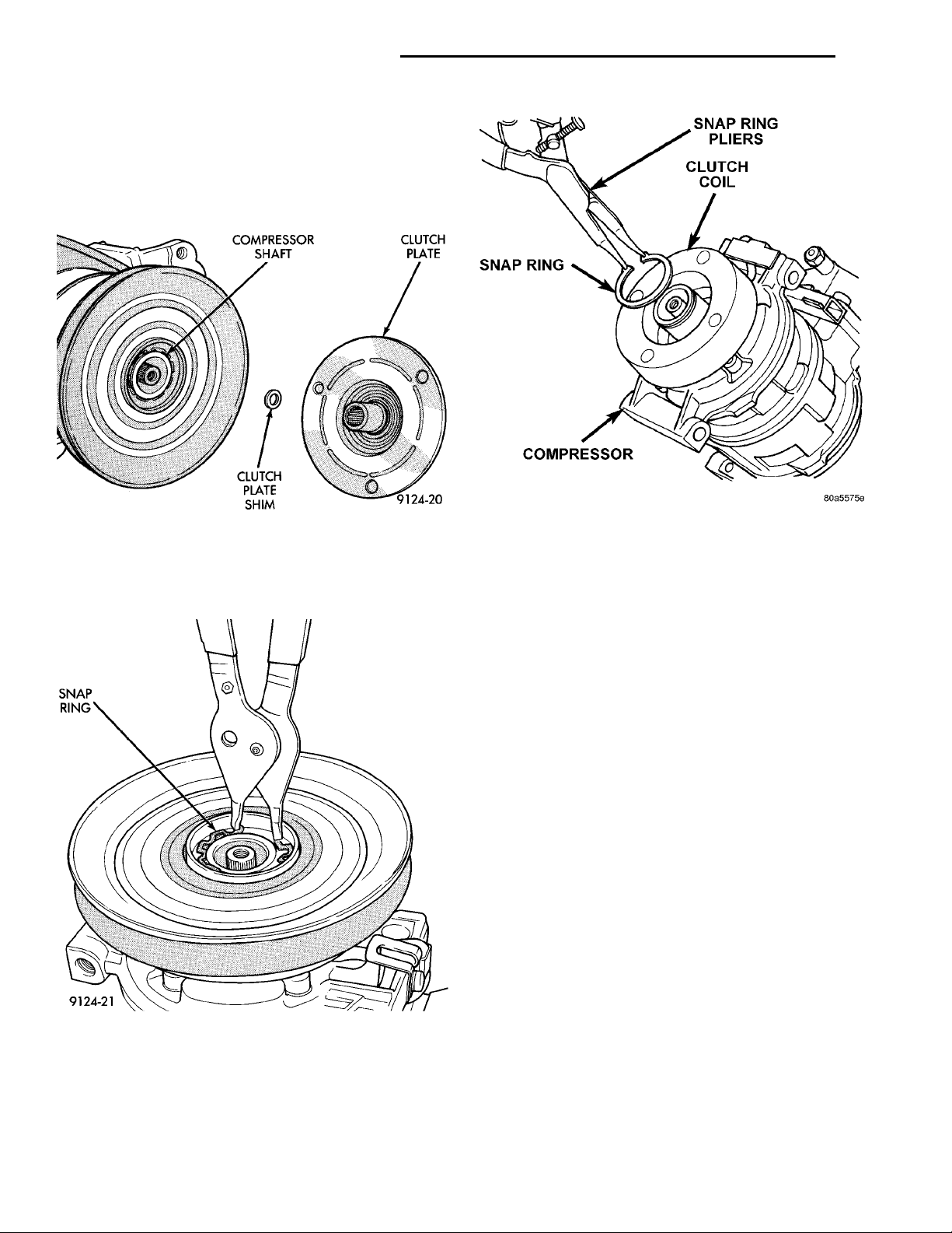
(2) Tap the clutch plate with a plastic hammer and
remove clutch plate and shim(s) (Fig. 24).
COMPRESSORSHAFT CLUTCHPLATECLUTCHPLATE SHIM
CAUTION: Do not use screwdrivers between the
clutch plate assembly and pulley to remove front
SNAP RING
plate as this may damage the front plate assembly.
Fig. 24 Clutch Plate and Shim(s)
(3) Remove pulley retaining snap ring with Snap
Ring Pliers, and slide pulley assembly off of compressor (Fig. 25).
Fig. 26 Clutch Coil Snap Ring
(6) Examine frictional faces of the clutch pulley
and front plate for wear. The pulley and front plate
should be replaced if there is excessive wear or scoring. If the friction surfaces are oily, inspect the shaft
nose area of the compressor for oil and remove the
felt from the front cover. If the compressor felt is saturated with oil, the shaft seal is leaking and will
have to be replaced.
(7) Check bearing for roughness or excessive leakage of grease. Replace bearing as required.
Fig. 25 Removing Pulley Snap Ring
(4) Remove coil wire bracket/ground clip screw and
wire harness.
(5) Remove snap ring retaining field coil onto compressor housing (Fig. 26). Slide field coil off of compressor housing.
INSTALLATION
(1) Align pin in back of field coil with hole in compressor end housing, and position field coil into place.
Make sure that lead wires are properly routed, and
fasten the coil wire bracket/ground retaining screw.
NOTE: The bevel side of the snap ring must be outward.
(2) Install field coil retaining snap ring with Snap
Ring Pliers. Press snap ring to make sure it is properly seated in the groove.
CAUTION: If snap ring is not fully seated it will
vibrate out, resulting in a clutch failure and severe
damage to the front face of the compressor.
Do not mar the pulley frictional surface.
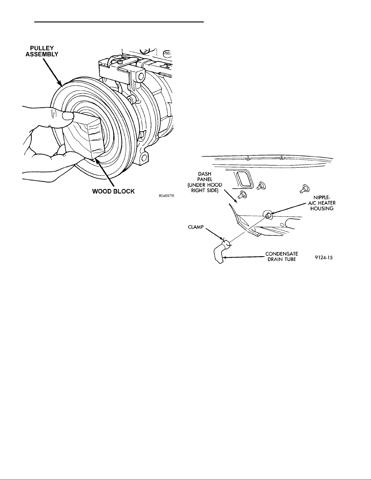
(3) Install pulley assembly to compressor. If necessary, tap gently with a block of wood on the friction
surface (Fig. 27).
(4) Install pulley assembly retaining snap ring
(bevel side outward) with Snap Ring Pliers. Press the
Page 21
PULLEY ASSEMBLYWOOD BLOCK
PL HEATING AND AIR CONDITIONING 24 - 21
REMOVAL AND INSTALLATION (Continued)
friction surfaces and provide a higher clutch torque
capability.
CONDENSATION DRAIN TUBE
REMOVAL
(1) Raise vehicle.
(2) Locate rubber drain tube on right side of dash
panel (Fig. 28).
(3) Squeeze clamp and remove drain tube.
DASH PANEL (UNDERHOOD RIGHT SIDE)CLAMP CONDENSATE DRAINTUBE NIPPLE-A/CHEATER HOUS-ING
INSTALLATION
To install, reverse the preceding operation. Check
the drain tube nipple on the heater-A/C housing for
any obstructions.
Fig. 27 Installing Pulley Assembly
snap ring to make sure it is properly seated in the
groove.
(5) If the original front plate assembly and pulley
assembly are to be reused, the old shim(s) can be
used. If not, place a trial stack of shims, 2.54 mm
(0.10 in.) thick, on the shaft against the shoulder.
(6) Install front plate assembly onto shaft.
(7) If installing a new front plate and/or pulley
assembly, the gap between front plate and pulley face
must be checked. Use the following procedure:
(a) Attach a dial indicator to front plate so that
movement of the plate can be measured.
(b) With the dial indicator zeroed on the front
plate, energize the clutch and record the amount of
movement.
(c) The readings should be 0.35 to 0.65 mm
(0.014 to 0.026 in.). If proper reading is not
obtained, add or subtract shims until desired reading is obtained.
(8) Install compressor shaft bolt. Tighten to 17.5
6 2 N·m (155 6 20 in. lbs.) torque.
NOTE: Shims may compress after tightening shaft
nut. Check air gap in four or more places to verify if
air gap is still correct. Spin pulley for final check.
CLUTCH BREAK-IN
After new clutch installation, cycle the A/C clutch
20 times (5 seconds on and 5 seconds off). During
this procedure, set the system to the A/C mode,
engine rpm at 1500 - 2000, and high blower speed.
This procedure (burnishing) will seat the opposing
Fig. 28 Condensate Water Drain Tube – Typical
CONDENSER
The condenser is located in front of the engine
radiator. It has no serviceable parts. If damaged or
leaking, the condenser assembly must be replaced.
WARNING: THE REFRIGERANT MUST BE
REMOVED FROM THE SYSTEM BEFORE REMOVING THE CONDENSER.
REMOVAL
(1) Using a R-134a refrigerant recovery machine,
remove the refrigerant from the A/C system.
(2) Remove battery support strut.
(3) Remove refrigerant lines from condenser.
(4) Remove upper radiator mounts.
(5) Remove condenser to radiator mounting
screws.
(6) Tilt radiator back and remove condenser.
INSTALLATION
For installation, reverse the above procedures.
Page 22
SUCTION LINE DISCHARGELINECOMPRESSOR MANIFOLD
FOAMSEAL EVAPORATORCONNECTION
CASEHALVES EVAPORATOR BLOWERWHEEL
24 - 22 HEATING AND AIR CONDITIONING PL
REMOVAL AND INSTALLATION (Continued)
DISCHARGE LINE
WARNING: THE REFRIGERANT SYSTEM MUST BE
RECOVERED BEFORE SERVICING ANY PART OF
THE REFRIGERANT SYSTEM.
REMOVAL
(1) Using a R-134a refrigerant recovery machine,
remove the refrigerant from A/C system.
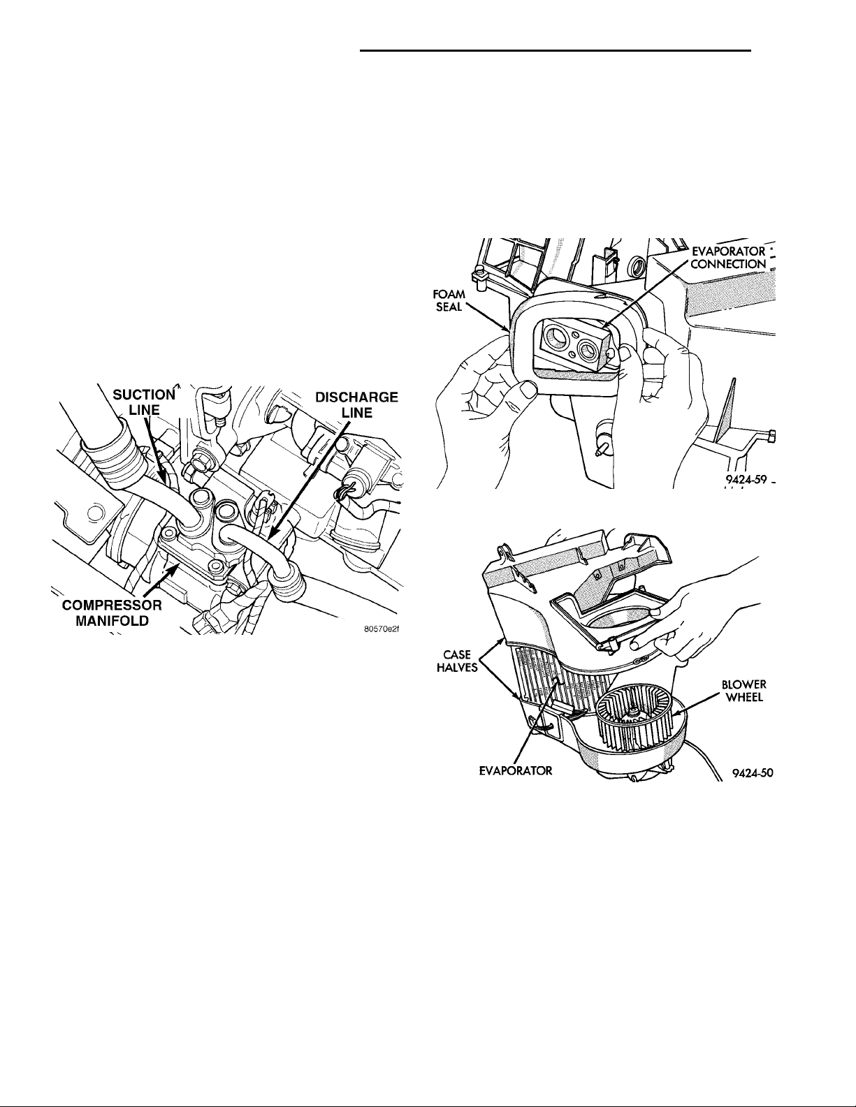
(2) From the top side of the vehicle, remove line at
compressor (Fig. 29).
(3) From the bottom side of the vehicle, remove
line at condenser.
INSTALLATION
For installation, reverse the above procedures.
(3) Disconnect fin sensing switch from harness.
(4) Remove upper to lower case retaining clips and
screws.
(5) Separate the case halves (Fig. 31).
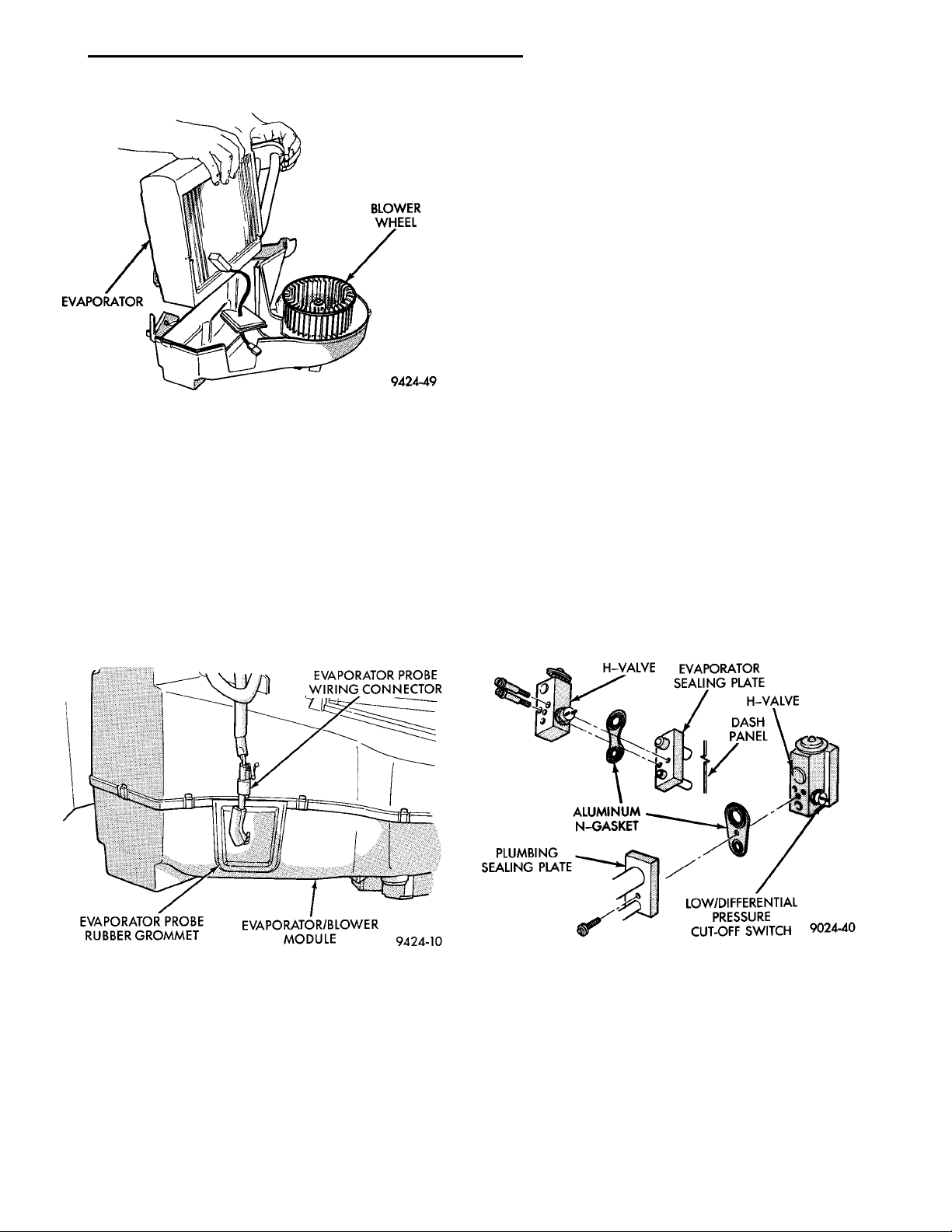
(6) Lift the evaporator out of the module (Fig. 32).
ASSEMBLE
To reassemble, reverse the above procedures.
Fig. 30 Foam Seal Removal
Fig. 29 Discharge Line
EVAPORATOR
This vehicle uses an aluminum plate and fin style
evaporator. It is located in the Evaporator/Blower
module.
The unit housing must be removed from the vehicle before beginning with this procedure. Refer to
Unit Housing in this section for removal procedure.
Use this procedure if any or all of the following
items require service:
• Evaporator
• Air inlet duct
• Recirculation door
• Evaporator/Blower module case
DISASSEMBLE
The RHD vehicle Unit Housing does not separate,
and is only one unit.
(1) Remove the clips and screws that hold the Unit
Housing to the Evaporator/Blower Module. Then separate the two units.
(2) Remove the evaporator to dash panel foam seal
(Fig. 30).
Fig. 31 Case Separation
EVAPORATOR PROBE
The evaporator probe can be removed without
removing the Unit Housing from the vehicle.
REMOVAL
(1) Disconnect probe wiring connector from behind
the glove box.
(2) Remove rubber grommet from evaporator/
blower module (Fig. 33).
(3) Note which of the three pilot holes the evapo-
rator probe is located in.
(4) Pull probe out of evaporator fins.
Page 23
EVAPORATOR BLOWERWHEEL
EVAPORATOR PROBE WIRINGCONNECTOREVAPORATOR PROBERUBBER GROMMET EVAPORATOR/BLOWERMODULE
PL HEATING AND AIR CONDITIONING 24 - 23
REMOVAL AND INSTALLATION (Continued)
(2) Remove the center bolt of refrigerant line
plumbing sealing plate (Fig. 34).
(3) Carefully pull the refrigerant line-sealing plate
assembly from the expansion valve towards front of
vehicle. Do not scratch the expansion valve sealing
surfaces with pilot tubes.
(4) Cover the openings on A/C line-sealing plate
assembly to prevent contamination.
(5) Remove two screws securing the expansion
valve to the evaporator sealing plate.
(6) Carefully remove valve.
INSTALLATION
(1) Remove and replace the aluminum gasket on
the evaporator sealing plate.
(2) Carefully hold the expansion valve to the evap-
Fig. 32 Evaporator Removal
INSTALLATION
(1) There are three pilot holes available for the
probe. The top hole is for service. If top hole was not
used by previous probe, install probe in top hole.
(2) If previous probe was removed from top hole,
use a small plastic stick and make a new hole. Make
the hole 1/4 inch above or below the original hole in
the evaporator core.
(3) Insert new probe into hole between evaporator
fins.
(4) Reinstall rubber grommet into evaporator
probe access hole.
orator sealing plate so not to scratch the sealing surface. Install two screws and tighten to 11 6 3 N·m
(100 6 30 in. lbs.).
(3) Remove and replace the aluminum gasket on
the refrigerant line- sealing plate assembly.
(4) Carefully hold the refrigerant line-sealing plate
assembly to the expansion valve. Install bolt and
tighten to 23 6 3 N·m (200 6 30 in. lbs.).
(5) Connect wires to low pressure cut-off switch.
ALUMINUMN-GASKETPLUMBING SEAL-ING PLATE LOW/DIFFERENTIALPRESSURE CUT-OFF SWITCHDASH PANEL H-VALVEEVAPORATOR SEALINGPLATEH-VALVE
(6) Evacuate and recharge system.
(7) After expansion valve is installed, system is
charged, and leaks have been checked, repeat A/C
performance check.
Fig. 33 Evaporator Probe Location
EXPANSION VALVE
WARNING: THE REFRIGERATION SYSTEM MUST
BE COMPLETELY EMPTY BEFORE PROCEEDING
WITH THIS OPERATION.
REMOVAL
(1) Remove the boot-type wire connector from the
pressure cut-off switch.
Fig. 34 Expansion Valve
A/C FILTER/DRIER
The filter/drier is mounted in a rubber grommet on
the right side of the engine compartment. The refrigerant must be recovered from the A/C system before
replacing the filter/drier assembly.
WARNING: THE REFRIGERATION SYSTEM MUST
BE COMPLETELY RECOVERED BEFORE PROCEEDING WITH THIS OPERATION.
Page 24
24 - 24 HEATING AND AIR CONDITIONING PL
REMOVAL AND INSTALLATION (Continued)
REMOVAL
(1) Disconnect liquid line from filter/drier.
(2) Disconnect liquid line on suction line assembly
from filter/drier.
(3) Pull filter/drier out of rubber grommet.
INSTALLATION
For installation, reverse the above procedures.
HIGH PRESSURE CUT OUT SWITCH
WARNING: THE REFRIGERANT MUST BE
REMOVED FROM THE SYSTEM BEFORE REMOVING THE HIGH PRESSURE CUT OUT SWITCH.
REMOVAL
(1) Disconnect wiring connector at the switch (Fig.
35).
HIGH PRESSURE RELIEFVALVEHIGH PRESSURE CUT-OUTSWITCHCOMPRESSOR MANIFOLD
(2) Remove internal snap ring.
(3) Pull switch out of manifold.
INSTALLATION
For installation, reverse the above procedures.
POTENTIALLY DANGEROUS AND MAY RESULT IN
FIRE OR EXPLOSION CAUSING INJURY OR PROPERTY DAMAGE.
REMOVAL
(1) Using a R-134a refrigerant recovery machine,
remove the refrigerant from A/C system.
(2) Rotate the high pressure relief valve counterclockwise and separate relief valve from the vehicle
(Fig. 35).
INSTALLATION
For installation, reverse the above procedures
using a new O-ring seal. Evacuate and charge the
refrigerant system.
HEATER CORE
Refer to Air Distribution Recondition of this section
for heater core removal procedure.
HEATER HOSES
CAUTION: When removing hoses from heater core
inlet or outlet nipples DO NOT exert excess pressure. The heater core may become damaged and
leak engine coolant.
Fig. 35 High Pressure Relief Valve Location
HIGH PRESSURE RELIEF VALVE
WARNING: AVOID BREATHING A/C REFRIGERANT
AND LUBRICANT VAPOR OR MIST. EXPOSURE MAY
IRRITATE EYES, NOSE AND THROAT. USE ONLY
APPROVED SERVICE EQUIPMENT MEETING SAE
REQUIREMENTS TO DISCHARGE R-134a SYSTEM.
IF ACCIDENTAL SYSTEM DISCHARGE OCCURS,
VENTILATE WORK AREA BEFORE RESUMING SERVICE.
R-134a SERVICE EQUIPMENT OR VEHICLE A/C
SYSTEM SHOULD NOT BE PRESSURE TESTED OR
LEAK TESTED WITH COMPRESSED AIR. MIXTURE
OF AIR and R-134a CAN BE COMBUSTIBLE AT ELEVATED PRESSURES. THESE MIXTURES ARE
NOTE: Review Cooling System Precautions before
proceeding with this operation.
REMOVAL
(1) Drain engine cooling system. Refer to Group 7,
Cooling System.
(2) Remove clamp at end of heater hose to be
removed.
(3) RHD vehicles, heater hoses at the heater core
connection have quick connects (Fig. 36). The quick
connect consist of two pieces; a quick connect and
insert. The quick connect is removed by compressing
the insert with a pliers, pull quick connect free of
insert/nipple. Carefully compressed insert pulling the
quick connect from connector nipple. The insert will
remain on the connector nipple as the quick connect
is removed.
(4) Remove the heater hose clamp from the heater
hose at the block and remove hose.
INSTALLATION
NOTE: The insert should be remove from the connector nipple and place it in side of the quick connect.
For installation, reverse the above procedures.
Page 25
INSERTQUICK CONNECTCOMPRESS INSERT FORREMOVAL
EXPANSION VALVELOW PRESSURE CUT OFFSWITCHSUCTION LINECONTROL HEAD
PL HEATING AND AIR CONDITIONING 24 - 25
REMOVAL AND INSTALLATION (Continued)
Fig. 36 Heater Hose Quick Connect
LIQUID LINE
WARNING: THE REFRIGERATION SYSTEM MUST
BE COMPLETELY EMPTY BEFORE PROCEEDING
WITH THIS OPERATION.
REMOVAL
(1) Using a R-134a refrigerant recovery machine,
remove the refrigerant from A/C system.
(2) Disconnect liquid line at drier.
(3) Disconnect liquid line at condenser.
INSTALLATION
For installation, reverse the above procedures.
LOW PRESSURE CUT OFF SWITCH
WARNING: THE REFRIGERATION SYSTEM MUST
BE COMPLETELY RECOVERED BEFORE PROCEEDING WITH THIS OPERATION. REFER TO
REFRIGERANT RECOVERY SECTION.
REMOVAL
(1) Disconnect the boot like wire connector at the
cut off switch.
(2) Using a sender unit removal socket, remove the
switch from the expansion valve (Fig. 37).
Fig. 37 Low Pressure Cut-Off Switch and Expansion
Valve – Typical
REMOVAL
(1) Remove instrument panel upper cowl panel.
(2) Remove right side upper instrument panel
bezel (Fig. 38).
(3) Remove center vent duct (Fig. 39).
(4) Remove upper defrost duct (Fig. 40).
(5) Remove inner defrost duct (Fig. 41).
(6) Disconnect cable at heater unit.
(7) Disconnect cable at control panel.
(8) Remove cable from vehicle.
UPPER INSTRUMENT PANELBEZEL
INSTALLATION
For installation, reverse the above procedures,
adjust cable and test. Refer to Mode Control Cable
Adjustment at the end of this section.
INSTALLATION
NOTE: Verify the O-ring condition on the replacement switch.
For installation, reverse the above procedures.
Evacuate and charge the system.
MODE CONTROL CABLE
The Mode Control Cable can be removed and
installed without having to remove the instrument
panel from the vehicle.
Fig. 38 Bezel Removal
Page 26
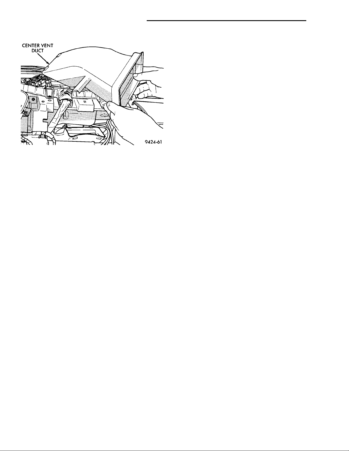
CENTER VENTDUCT
24 - 26 HEATING AND AIR CONDITIONING PL
REMOVAL AND INSTALLATION (Continued)
(2) Disconnect vacuum line from actuator (Fig. 42).
(3) Remove two nuts retaining vacuum actuator to
recirculation door housing.
(4) Disconnect actuator from recirc. door link.
(5) Remove recirculation door actuator from vehicle.
INSTALLATION
For installation, reverse the above procedures.
SUCTION LINE
WARNING: THE REFRIGERANT MUST BE RECOVERED BEFORE SERVICING ANY PART OF THE
REFRIGERANT SYSTEMS.
REMOVAL
Fig. 39 Instrument Panel Center Vent
RECIRCULATION CONTROL CABLE (RHD)
The instrument panel and unit housing must be
removed from the vehicle to gain access to the recirculation cable. Refer to Group 8E, Instrument Panel
for removal procedure.
REMOVAL
(1) Remove instrument panel from vehicle. Refer
to group 8E for procedure.
(2) Remove cable at control end.
(3) Remove cable at recirculation door end.
(1) Using a R-134a refrigerant recovery machine,
remove the refrigerant from A/C system.
(2) Remove retaining bolt at expansion valve (Fig. 43).
(3) Remove line at drier.
(4) Remove line at compressor.
INSTALLATION
For installation, reverse the above procedures.
TEMPERATURE CONTROL CABLE
The Control Cable can be removed and installed
without having to remove the instrument panel from
the vehicle.
INSTALLATION
For installation, reverse the above procedures,
adjust cable and test. See Recirculation Control
Cable Adjustment toward the end of this section.
RECIRCULATION DOOR ACTUATOR
The recirculation door actuator is a vacuum controlled actuator used to control movement of the recirculation door in air conditioned equipped vehicles.
The instrument panel must be removed from the
vehicle to gain access to the recirculation door actuator. Refer to
REMOVAL
(1) Remove instrument panel from vehicle. Refer
to Group 8E, Instrument Panel And Systems for
removal procedures.
REMOVAL
(1) Remove instrument panel upper cowl panel.
(2) Remove right side upper instrument panel
bezel (Fig. 38).
(3) Remove center vent duct (Fig. 39).
(4) Remove upper defrost duct (Fig. 40).
(5) Remove inner defrost duct (Fig. 41).
(6) Disconnect cable at heater unit.
(7) Disconnect cable at control panel. Remove con-
trol from instrument panel.
(8) Remove cable from vehicle.
INSTALLATION
For installation, reverse the above procedures,
adjust cable and test. See Temperature Control Cable
Adjustment in this section.
Page 27
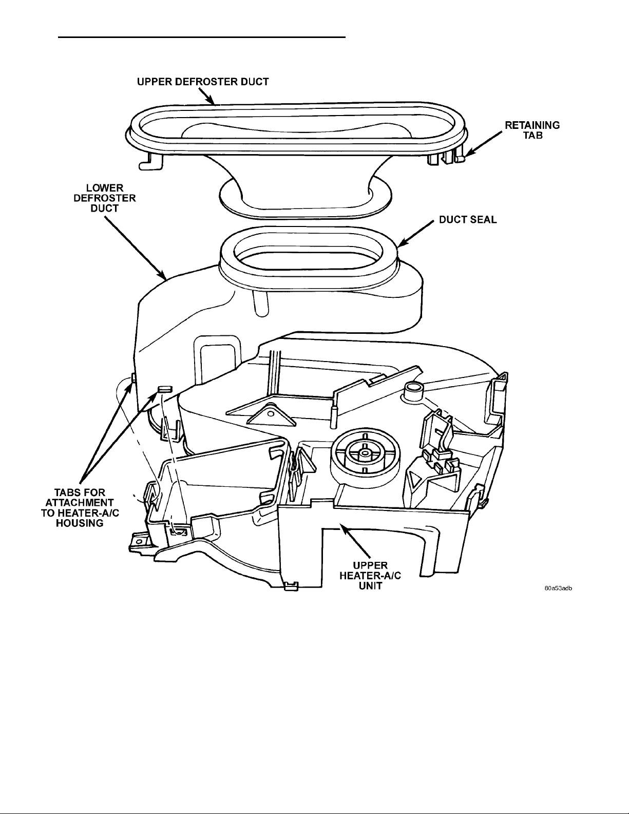
UPPER DEFROSTER DUCTRETAINING TABLOWER DEFROSTER DUCTDUCT SEALTABS FOR ATTACHMENT TOHEATER-A/C HOUSINGUPPER HEATER-A/C UNIT
PL HEATING AND AIR CONDITIONING 24 - 27
REMOVAL AND INSTALLATION (Continued)
Fig. 40 Instrument Panel Defrost Duct
Page 28
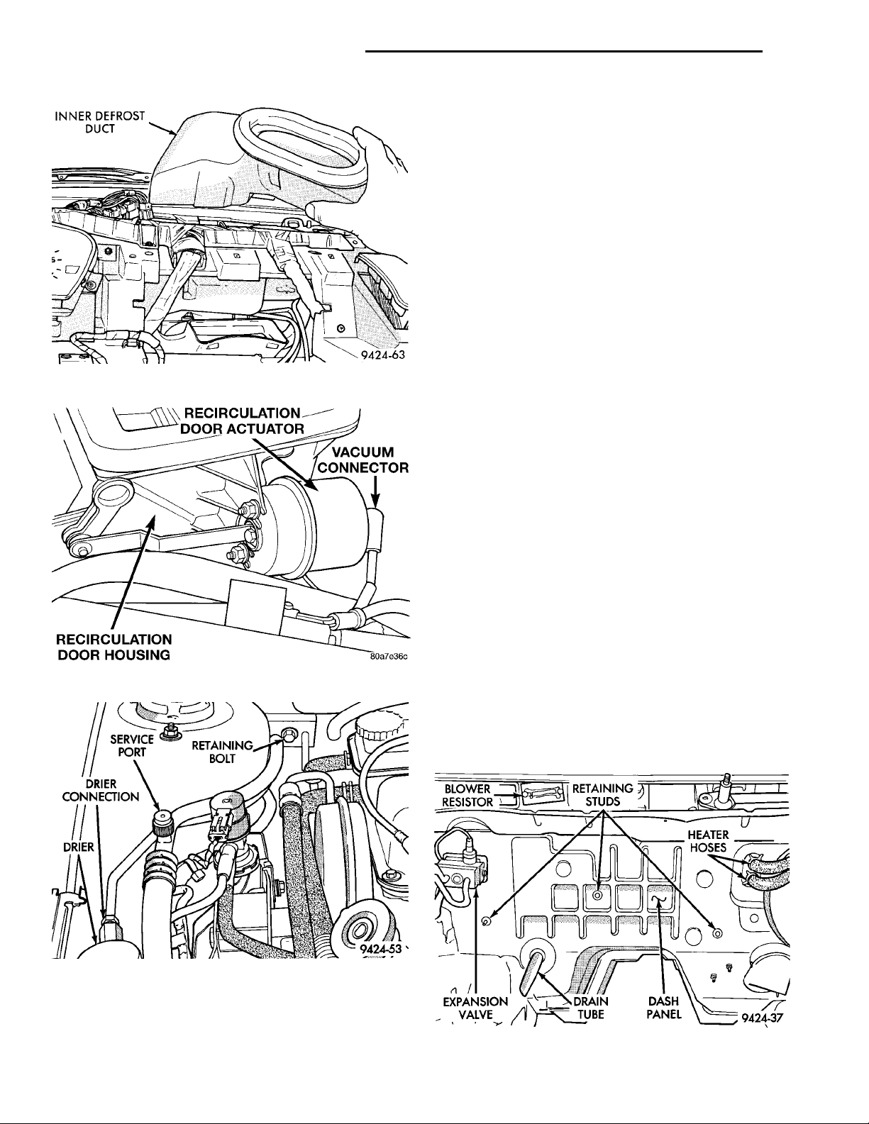
INNER DEFROSTDUCT
RECIRCULATION DOORACTUATORVACUUM CONNECTORRECIRCULATION DOORHOUSING
DRIER
RETAININGBOLTSERVICEPORTDRIER CONNECTION
24 - 28 HEATING AND AIR CONDITIONING PL
REMOVAL AND INSTALLATION (Continued)
UNIT HOUSING
The instrument panel must be removed in order to
remove the Unit Housing. Refer to group 8E Instrument Panel and Gauges for detailed procedure.
WARNING: THE R-134a REFRIGERANT SYSTEM
MUST BE RECOVERED BEFORE SERVICING ANY
PART OF THE REFRIGERANT SYSTEM.
REMOVAL
(1) Remove instrument panel from vehicle. Refer
to group 8E Instrument Panel and Gauges for
detailed procedure.
(2) Drain cooling system and remove heater hoses
at the dash panel. Place plugs in the heater core outlets to prevent coolant spillage during unit housing
removal.
Fig. 41 Instrument Panel Inner Defrost Duct
Fig. 42 Recirculation Door Actuator
(3) Using a refrigerant recovery machine, remove
the refrigerant from the A/C system, if equipped.
(4) Remove suction line at expansion valve. Place a
piece of tape over open refrigerant line to prevent
moisture and/or dirt from entering the line.
(5) Remove expansion valve from evaporator. Place
a piece of tape over open evaporator fitting to prevent moisture and/or dirt from entering the evaporator.
(6) Remove rubber drain tube extension from condensation drain tube.
(7) Remove three retaining nuts located in the
engine compartment, on the dash panel (Fig. 44).
(8) Remove the right side retaining screw (Fig. 45).
(9) Remove remaining nut located on dash panel
stud.
(10) Disconnect the blue five way connector from
the plenum. Module wiring harness must be removed
EXPANSIONVALVE DRAIN TUBE DASHPANEL
BLOWER
with module.
RESISTOR
(11) Remove assembly from the vehicle.
RETAININGSTUDS
HEATER
HOSES
Fig. 43 Bolt Removal
INSTALLATION
For installation, reverse the above procedures.
Fig. 44 Dash Panel Studs
Page 29
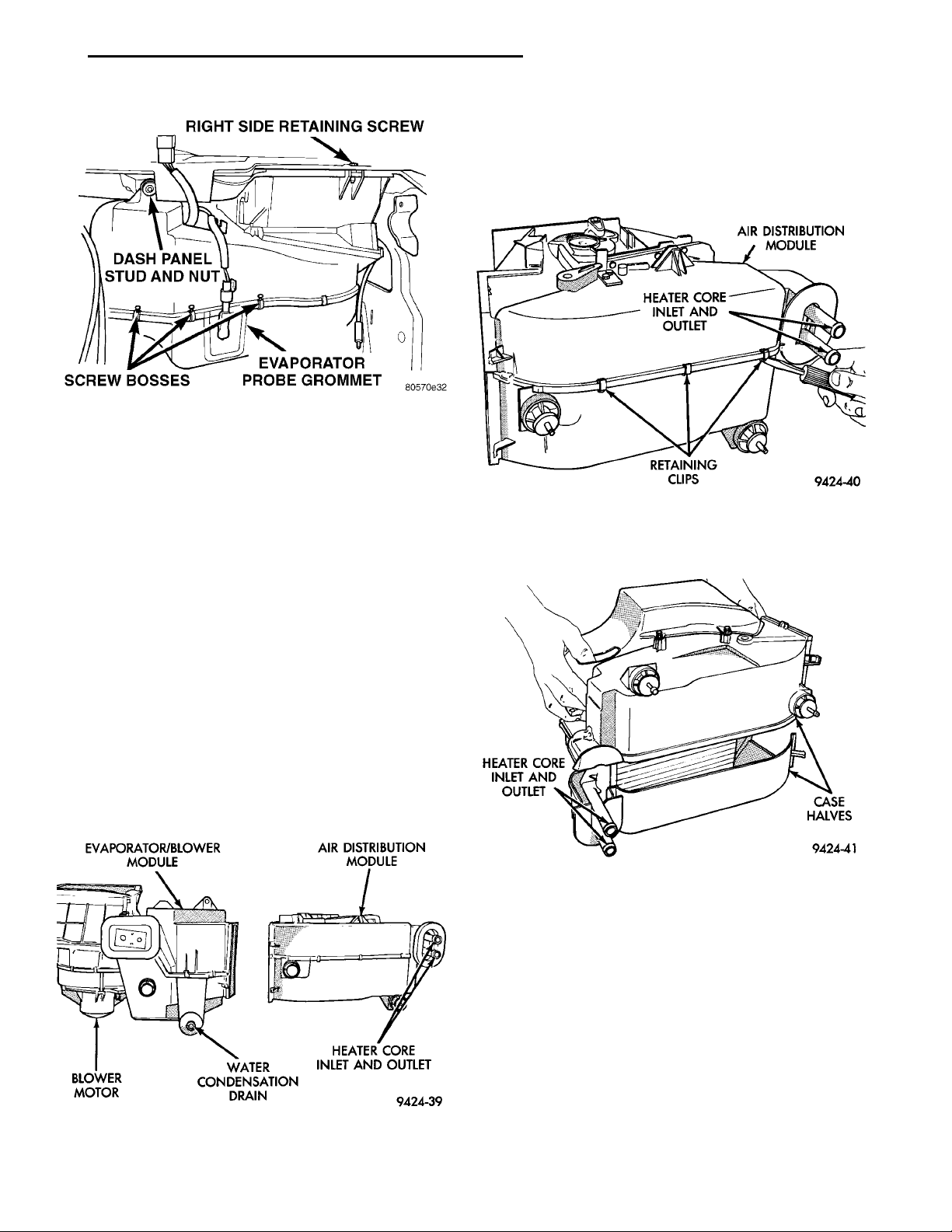
EVAPORATOR/BLOWERMODULEBLOWERMOTOR WATER CONDENSA-TION DRAIN HEATER COREINLET AND OUTLETAIR DISTRIBUTIONMODULE
RIGHT SIDE RETAININGSCREWEVAPORATOR PROBEGROMMETSCREW BOSSESDASH PANEL STUDAND NUT
HEATER COREINLET AND OUT-LET CASEHALVES
AIR DISTRIBUTIONMODULEHEATER COREINLET AND OUT-LETRETAININGCLIPS
PL HEATING AND AIR CONDITIONING 24 - 29
(2) Remove the panel opening foam seal, demister
opening foam seal, and heater core tube foam seals
from unit.
(3) Remove the retaining clips and screws that
hold the upper and lower housings together (Fig. 47).
Fig. 45 Retaining Screws
DISASSEMBLY AND ASSEMBLY
AIR DISTRIBUTION MODULE – RECONDITION
Use this procedure if any or all of the following
items require service:
• Heater core
• Temperature door
• Mode door
• Heat/Defrost door
• Assembly housing
The unit housing must be removed from the vehicle before beginning with this procedure. Refer to
Unit Housing in this section for removal procedure.
DISASSEMBLE
For RHD vehicles, the Unit Housing does not separate. It is a one piece unit and must be replaced as
a whole.
(1) Remove the clips and screws that hold the Air
Distribution Module to the Evaporator/Blower Module. Then separate the two units (Fig. 46).
Fig. 47 Retaining Clip Removal
(4) Place the unit in the upside down position.
Then separate the two halves of the module (Fig. 48).
Fig. 48 Case Separation
Fig. 46 Air Distribution and Evaporator/Blower
Module Separation
Page 30
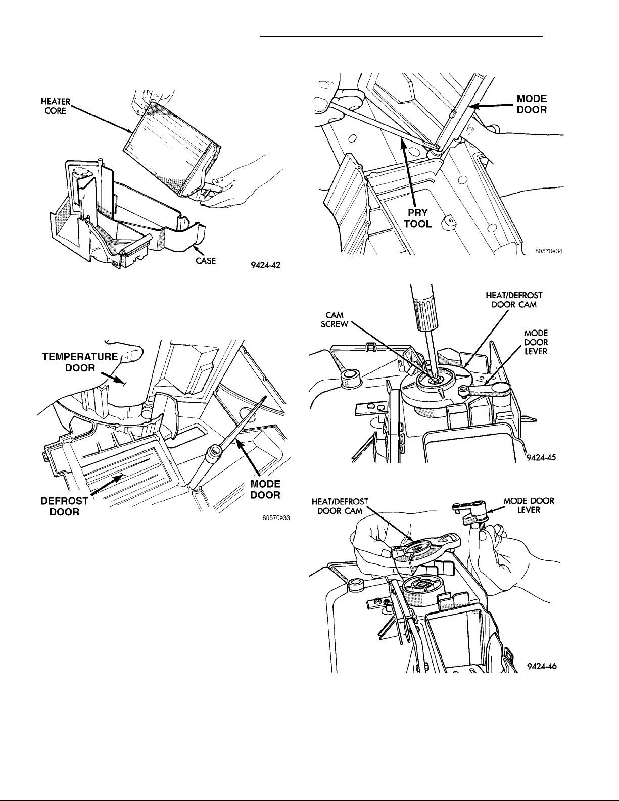
HEATER CORE CASE
24 - 30 HEATING AND AIR CONDITIONING PL
DISASSEMBLY AND ASSEMBLY (Continued)
TEMPERATURE DOOR MODE DOORDEFROST DOOR
(5) Lift the heater core out of the case (Fig. 49).
Fig. 49 Heater Core Removal
(6) Press tab in at base of temperature door and
release door from lever (Fig. 50). Then remove the
door.
HEAT/DEFROSTDOOR CAM MODE DOORLEVER
CAM SCREW HEAT/DEFROST DOOR CAMMODE DOORLEVER
Fig. 51 Mode Door Removal
Fig. 52 Cam Screw Removal
Fig. 50 Temperature Door Removal
(7) Press tab in at base of mode door and release
door from lever (Fig. 51).
(8) Remove Heat/Defrost door cam screw (Fig. 52).
(9) Lift the cam and mode door lever off of the
housing (Fig. 53).
(10) Remove the Heat/Defrost link pivot screw
(Fig. 54).
(11) Lift the Heat/Defrost link and the door as an
assembly. Then separate the link from the door.
ASSEMBLE
To reassemble, reverse the above procedures.
Fig. 53 Cam and Lever Removal
Page 31
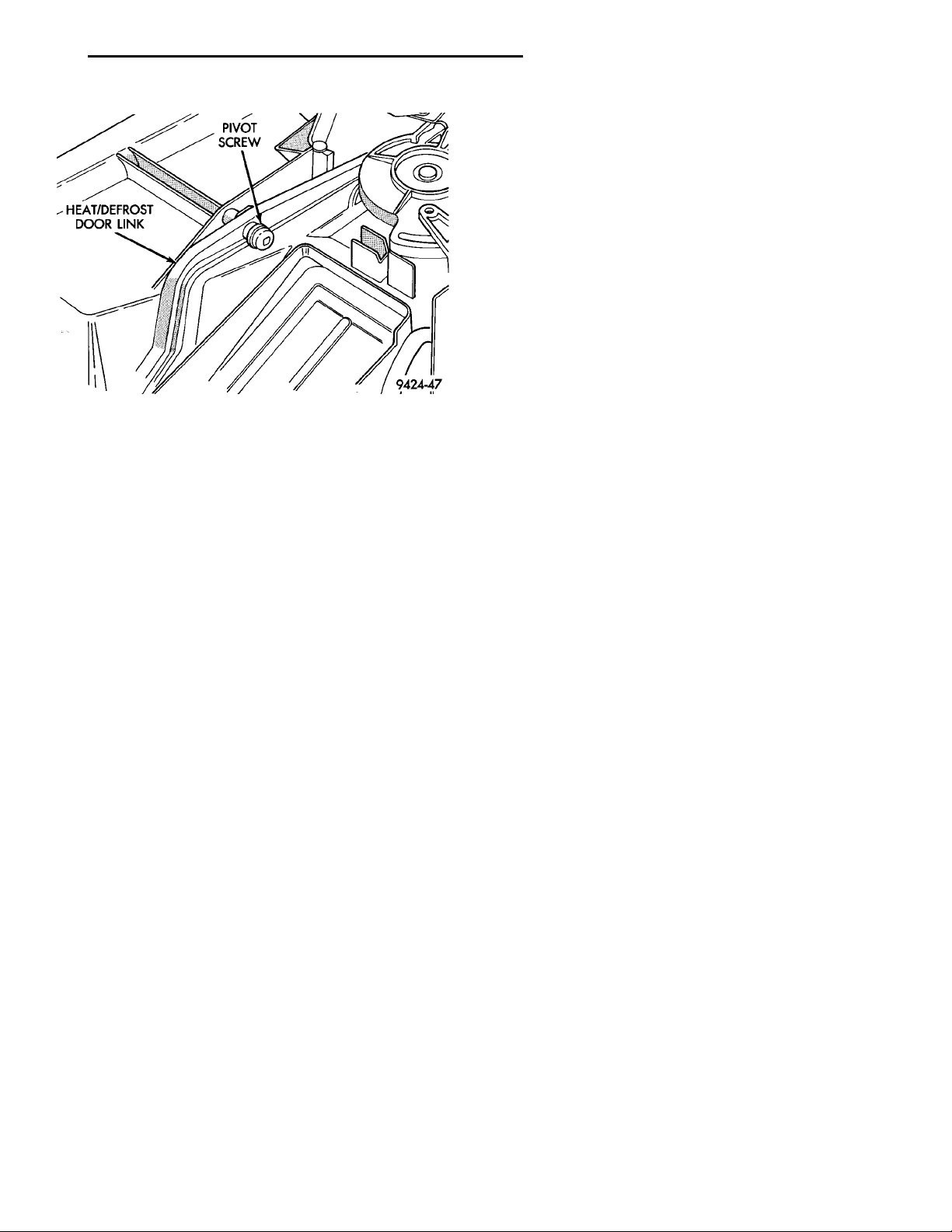
HEAT/DEFROST DOOR
LINK
PIVOTSCREW
PL HEATING AND AIR CONDITIONING 24 - 31
(5) Then snap the cable hold down clip into posi-
tion.
RECIRCULATION CONTROL CABLE (RHD)
(1) Attach cable to actuator arm on recirc. door
and clip black casing against the stop.
(2) Attach other end of cable to instrument panel
control.
(3) Turn the recirc. knob completely counterclock-
wise.
(4) While holding the knob in the counterclockwise
position, pull on the black casing of the recirc. cable.
This will take up any free play in the cable and index
the recirc. door to the recirc. knob.
TEMPERATURE CONTROL CABLE
Fig. 54 Pivot Screw Removal
ADJUSTMENTS
MODE CONTROL CABLE
(1) Attach cable to actuator arm on mode door and
clip black casing against the stop.
(2) Attach other end of cable to instrument panel
control.
(3) Turn the mode knob completely counterclock-
wise.
(4) While holding the knob in the counterclockwise
position, pull on the black casing of the mode cable.
This will take up any free play in the cable and index
the mode door to the mode knob.
(1) Attach cable to actuator arm on temperature
door and clip black casing against the stop.
(2) Attach other end of cable to instrument panel
control.
(3) Turn the temperature knob completely counter-
clockwise.
(4) While holding the knob in the counterclockwise
position, pull on the black casing of the temperature
cable. This will take up any free play in the cable
and index the temperature door to the temperature
knob.
(5) Then snap the cable hold down clip into position.
(6) Remount control.
Page 32

 Loading...