

Page 1

PL BODY 23 - 1
BODY
CONTENTS
page page
BODY COMPONENTS .................... 16
GENERAL SERVICE INFORMATION .......... 1
PAINT ................................. 2
GENERAL SERVICE INFORMATION
INDEX
page
GENERAL INFORMATION
SAFETY PRECAUTIONS AND WARNINGS .... 1
GENERAL INFORMATION
SAFETY PRECAUTIONS AND WARNINGS
WARNING: EYE PROTECTION SHOULD BE USED
WHEN SERVICING GLASS COMPONENTS. PERSONAL INJURY CAN RESULT.
USE A OSHA APPROVED BREATHING FILTER
WHEN SPRAYING PAINT OR SOLVENTS IN A CONFINED AREA. PERSONAL INJURY CAN RESULT.
AVOID PROLONGED SKIN CONTACT WITH
PETROLEUM OR ALCOHOL– BASED CLEANING
SOLVENTS. PERSONAL INJURY CAN RESULT.
DO NOT STAND UNDER A HOISTED VEHICLE
THAT IS NOT PROPERLY SUPPORTED ON SAFETY
STANDS. PERSONAL INJURY CAN RESULT.
CAUTION: When holes must be drilled or punched
in an inner body panel, verify depth of space to the
outer body panel, electrical wiring, or other components. Damage to vehicle can result.
Do not weld exterior panels unless combustible
material on the interior of vehicle is removed from
the repair area. Fire or hazardous conditions, can
result.
Always have a fire extinguisher ready for use
when welding.
Disconnect the negative (-) cable clamp from the
battery when servicing electrical components that
are live when the ignition is OFF. Damage to electrical system can result.
SEATS ................................. 8
STATIONARY GLASS ..................... 4
SUNROOF ............................. 11
Do not use abrasive chemicals or compounds on
painted surfaces. Damage to finish can result.
Do not use harsh alkaline based cleaning solvents on painted or upholstered surfaces. Damage
to finish or color can result.
Do not hammer or pound on plastic trim panel
when servicing interior trim. Plastic panels can
break.
Chrysler Corporation uses many different types of
push-in fasteners to secure the interior and exterior
trim to the body. Most of these fasteners can be
reused to assemble the trim during various repair
procedures. At times, a push-in fastener cannot be
removed without damaging the fastener or the component it is holding. If it is not possible to remove a
fastener without damaging a component or body, cut
or break the fastener and use a new one when
installing the component. Never pry or pound on a
plastic or pressed-board trim component. Using a
suitable fork-type prying device, pry the fastener
from the retaining hole behind the component being
removed. When installing, verify fastener alignment
with the retaining hole by hand. Push directly on or
over the fastener until it seats. Apply a low-force pull
to the panel to verify that it is secure.
When it is necessary to remove components to service another, it should not be necessary to apply
excessive force or bend a component to remove it.
Before damaging a trim component, verify hidden
fasteners or captured edges holding the component in
place.
Page 2

23 - 2 BODY PL
PAINT
INDEX
page page
GENERAL INFORMATION
AFTERMARKET PAINT REPAIR PRODUCTS . . . 3
BASE COAT/CLEAR COAT FINISH ........... 2
GENERAL INFORMATION
PAINT CODE
A paint code is provided on the body code plate
located in the engine compartment. Refer to the
Introduction section at the front of this manual for
body code plate description. The paint and trim codes
are also included on the Vehicle Safety Label located
on the driver’s door end frame.
BASE COAT/CLEAR COAT FINISH
On most vehicles a two-part paint application (base
coat/clear coat) is used. Color paint that is applied to
primer is called base coat. The clear coat protects the
base coat from ultraviolet light and provides a durable high-gloss finish.
WET SANDING, BUFFING, AND POLISHING
Minor acid etching, orange peel, or smudging in
clear coat or single-stage finishes can be reduced
with light wet sanding, hand buffing, and polishing.
If the finish has been wet sanded in the past, it
cannot be repeated. Wet sanding operation
should be performed by a trained automotive
paint technician.
CAUTION: Do not remove clear coat finish, if
equipped. Base coat paint must retain clear coat for
durability.
PAINT CODE ........................... 2
PAINTED SURFACE TOUCHUP ............. 2
WET SANDING, BUFFING, AND POLISHING . . . 2
PAINTED SURFACE TOUCHUP
When a painted metal surface has been scratched
or chipped, it should be touched-up as soon as possible to avoid corrosion. For best results, use Mopart
Scratch Filler/Primer, Touch-Up Paints and Clear Top
Coat. Refer to Introduction group of this manual for
Body Code Plate information.
TOUCHUP PROCEDURE
(1) Scrape loose paint and corrosion from inside
scratch or chip.
(2) Clean affected area with Mopart Tar/Road Oil
Remover, and allow to dry.
(3) Fill the inside of the scratch or chip with a coat
of filler/primer. Do not overlap primer onto good surface finish. The applicator brush should be wet
enough to puddle-fill the defect without running. Do
not stroke brush applicator on body surface. Allow
the filler/primer to dry hard.
(4) Cover the filler/primer with color touch-up
paint. Do not overlap touchup color onto the original
color coat around the scratch or chip. Butt the new
color to the original color, if possible. Do not stroke
applicator brush on body surface. Allow touchup
paint to dry hard.
(5) On vehicles without clear coat, the touchup
color can be lightly wet sanded (1500 grit) and polished with rubbing compound.
(6) On vehicles with clear coat, apply clear top coat
to touchup paint with the same technique as
described in Step 4. Allow clear top coat to dry hard.
If desired, Step 5 can be performed on clear top coat.
Page 3
PL BODY 23 - 3
GENERAL INFORMATION (Continued)
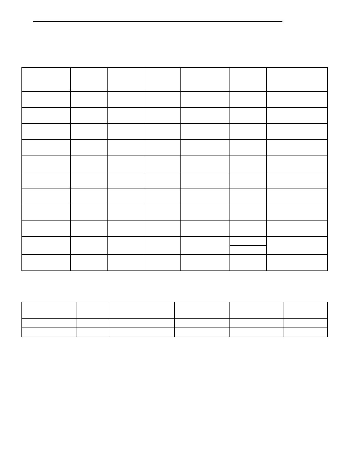
AFTERMARKET PAINT REPAIR PRODUCTS
1997 EXTERIOR COLORS
EXTERIOR
COLOR
Magenta Clear
Coat
Flame Red
Clear Coat
Strawberry
Pearl Coat
Deep Amethyst
Pearl Coat
Emerald Green
Pearl Coat
Bright Jade
Satin Glow
Lapis Blue
Clear Coat
Brilliant Blue
Pearl Coat
Light Iris Pearl
Coat
Black Clear
Coat
Bright White
Clear Coat
CHRY
CODE*
SH1 74171 26079 B9615 51522 CHA96:SH1
PR4 4679 23043 B9326 4691 CHA93:PR4
PRE 4791 24074 B9454 48542 CHA94:PRE
TCN 5246 27038 B9736 52566 CHA97:TCN
PGS 4785 24075 B9460 48539 CHA94:PGS
SQM 18885 26094 B9620 51534 CHA96:SQM
RC4 4935 24098 B9531 50218 CHA95:RC4
PCH 4784 24073 B9452 48538 CHA94:PCH
PC5 4788 24078 B9455 48782 CHA94:PC5
DX8 9700 15214 99 35858 CHA85:DX8
GW7 4037 18238 B8833 37298 CHA88:GW
PPG BASF DUPONT
S-W
ACME
M-S
90-5950
AKZO NOBEL
SIKKENS
*Herberts Standox and Spies Hecker use the Chrysler paint code as listed on the Body Code Plate.
1997 INTERIOR COLORS
INTERIOR
COLOR
Agate AZ 9856/2-1461 22135 C9208 45994
Camel K5 27731 26120 C9603 51541
CHRY
CODE
PPG BASF DUPONT
S-W ACME
M-S
Page 4

23 - 4 BODY PL
STATIONARY GLASS
INDEX
page page
DESCRIPTION AND OPERATION
SAFETY PRECAUTIONS .................. 4
REMOVAL AND INSTALLATION
QUARTER GLASS ....................... 6
DESCRIPTION AND OPERATION
SAFETY PRECAUTIONS
WARNING: DO NOT OPERATE THE VEHICLE
WITHIN 24 HOURS OF WINDSHIELD INSTALLATION.
IT TAKES AT LEAST 24 HOURS FOR URETHANE
ADHESIVE TO CURE. IF IT IS NOT CURED, THE
WINDSHIELD MAY NOT PERFORM PROPERLY IN
AN ACCIDENT.
URETHANE ADHESIVES ARE APPLIED AS A SYSTEM. USE GLASS CLEANER, GLASS PREP SOLVENT, GLASS PRIMER, PVC (VINYL) PRIMER AND
PINCHWELD (FENCE) PRIMER PROVIDED BY THE
ADHESIVE MANUFACTURER. IF NOT, STRUCTURAL
INTEGRITY COULD BE COMPROMISED.
BE SURE TO REFER TO THE URETHANE MANUFACTURER’S DIRECTIONS FOR CURING TIME
SPECIFICATIONS, AND DO NOT USE ADHESIVE
AFTER ITS EXPIRATION DATE.
VAPORS THAT ARE EMITTED FROM THE URETHANE ADHESIVE OR PRIMER COULD CAUSE
PERSONAL INJURY. USE THEM IN A WELL-VENTILATED AREA.
SKIN CONTACT WITH URETHANE ADHESIVE
SHOULD BE AVOIDED. PERSONAL INJURY MAY
RESULT.
ALWAYS WEAR EYE AND HAND PROTECTION
WHEN WORKING WITH GLASS.
REAR WINDOW ......................... 7
WINDSHIELD ........................... 4
REMOVAL AND INSTALLATION
WINDSHIELD
The urethane adhesive holding the windshield to
the opening pinch weld (fence) can be cut using a
sharp cold knife from the exterior of the vehicle.
Using the cold knife method is effective if the windshield is already broken. If the glass must be salvaged, cutting the urethane adhesive from the
interior of the vehicle using a reciprocating or oscillating power knife is recommended.
RECOMMENDED TOOLS AND ADHESIVE
POWER KNIFE
• Feint Power Cut-out Knife
• Equalizert Magnum, Interior Auto Glass Cut
Out Knife
ADHESIVE, PRIMER AND CLEANER
The following urethane adhesive systems are OEM
certified and conform to the FMVSS 212 windshield
retention standard and the FMVSS 216 roof crush
standard.
• Essexy U-400 HV High Viscosity Adhesive
• Essexy U-400 Adhesive
• Essexy U-401 Glass Prep
• Essexy U-402 Glass Primer
• Essexy U-413 Pinchweld Primer
CAUTION: Protect all painted and trimmed surfaces
from coming in contact with urethane or primers.
Be careful not to damage painted surfaces when
removing moldings or cutting urethane around
windshield.
It is difficult to salvage a windshield during the
removal operation. The windshield is part of the
structural support for the roof. The urethane bonding
used to secure the windshield to the fence is difficult
to cut or clean from any surface. If the moldings are
set in urethane, it would also be unlikely they could
be salvaged. Before removing the windshield, check
the availability of the windshield and moldings from
the parts supplier.
WINDSHIELD REMOVAL—EXTERIOR METHOD
(1) Remove inside rear view mirror.
(2) Remove windshield wiper arms.
(3) Remove cowl cover.
(4) Place protective covers over instrument panel
and hood.
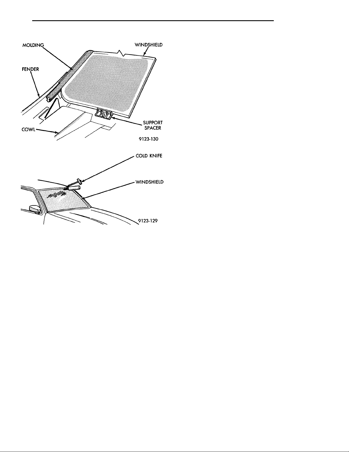
(5) Remove windshield moldings (Fig. 1) using a
suitable hook tool and trim stick.
(6) Using a sharp cold knife, cut urethane adhesive holding the windshield to the A-pillars, roof
header and cowl pinch weld fences (Fig. 2). A power
cutting device can be used if available.
(7) Separate windshield from vehicle.
Page 5
MOLDINGFENDERCOWL WINDSHIELDSUPPORTSPACER
COLD KNIFEWINDSHIELD
PL BODY 23 - 5
REMOVAL AND INSTALLATION (Continued)
(1) Place replacement windshield into windshield
opening and position glass in the center of the opening against the support spacers.
(2) Verify the glass lays evenly against the pinch
weld fence at the sides, top and bottom of the
replacement windshield. If not, the pinch weld fence
must be formed to the shape of the new glass.
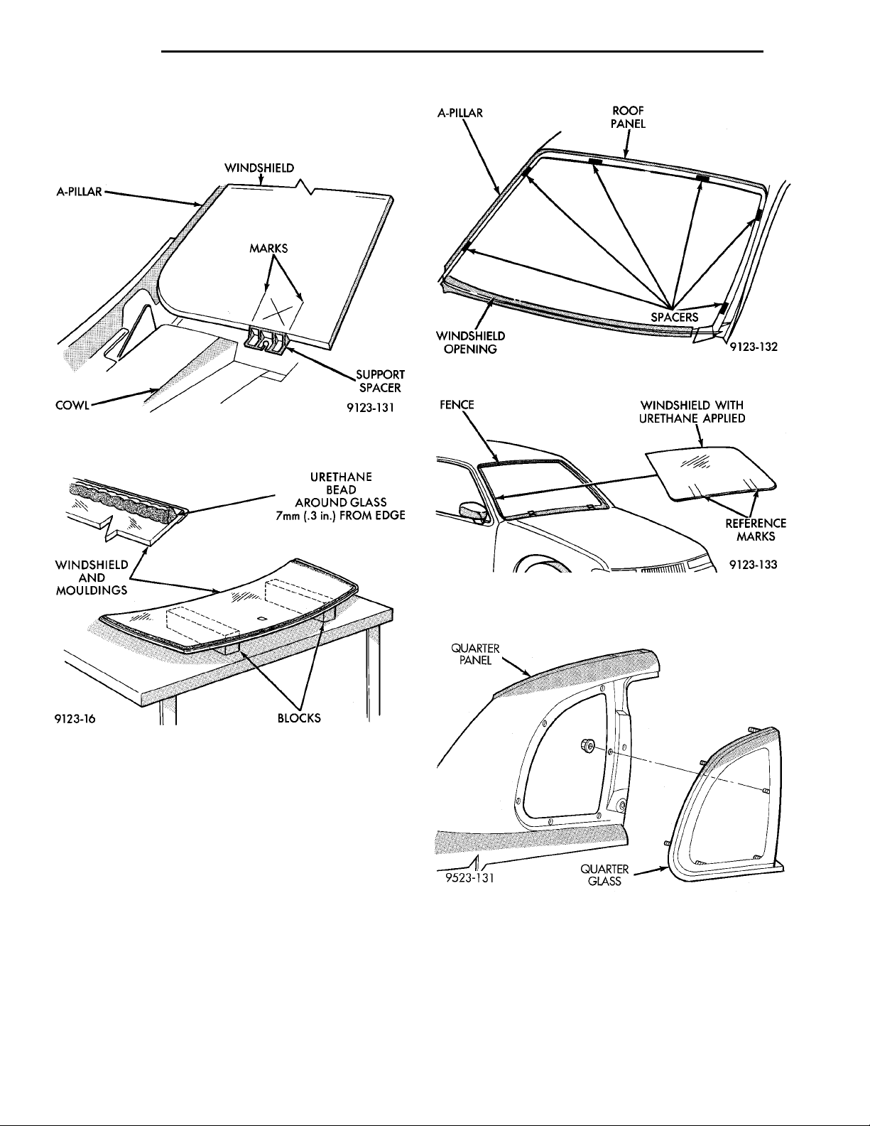
(3) Mark the glass at the support spacers with a
grease pencil or pieces of masking tape and ink pen
to use as a reference for installation (Fig. 3).
(4) Remove replacement windshield from windshield opening.
(5) Position the windshield inside up on a suitable
work surface with two padded, wood 10 cm by 10 cm
by 50 cm (4 in. by 4 in. by 20 in.) blocks, placed par-
Fig. 1 Windshield Molding
allel 75 cm (2.5 ft.) apart (Fig. 4).
WARNING: DO NOT USE SOLVENT BASED GLASS
CLEANER TO CLEAN WINDSHIELD BEFORE
APPLYING GLASS PREP AND PRIMER. POOR
ADHESION CAN RESULT.
Fig. 2 Cut Urethane Around Windshield
WINDSHIELD REMOVAL—INTERIOR METHOD
(1) Remove inside rear view mirror.
(2) Remove instrument panel top cover, refer to
Group 8E, Instrument Panel.
(3) Remove A-pillar trim covers.
(4) Place protective covers over instrument panel
and hood.
(5) Using a reciprocating or oscillating power
knife, cut urethane adhesive holding the windshield
to the A-pillars, roof header and cowl pinch weld
fences. Refer to instructions provided with the equipment being used.
(6) Separate windshield from vehicle.
WINDSHIELD INSTALLATION
CAUTION: Open the left front door glass before
installing windshield to avoid pressurizing the passenger compartment. If a door is slammed before
urethane bonding is cured, water leaks can result.
Allow the urethane at least 24 hours to cure
before returning the vehicle to use.
To avoid stressing the replacement windshield,
the urethane bonding material on the windshield
fence should be smooth and consistent to the
shape of the replacement windshield. The support
spacers should be cleaned and properly installed
on weld studs or repair screws at bottom of windshield opening.
(6) Clean inside of windshield with ammonia based
glass cleaner and lint-free cloth.
(7) Apply molding to perimeter of windshield.
(8) Apply Glass Prep adhesion promoter 25 mm (1
in.) wide around perimeter of windshield and wipe
with clean/dry lint-free cloth until no streaks are visible.
(9) Apply Glass Primer 25 mm (1 in.) wide around
perimeter of windshield. Allow at least three minutes
drying time.
(10) Using a razor knife, remove as much original
urethane as possible. Do not damage paint on windshield fence.
(11) Apply pinch weld primer 15 mm (.75 in.) wide
around the windshield fence. Allow at least three
minutes drying time.
(12) If a low viscosity urethane adhesive is used,
install compression spacers on the fence around the
windshield opening (Fig. 5).
(13) Apply a 10 mm (0.4 in.) bead of urethane on
centerline of windshield fence.
(14) With the aid of a helper, position the windshield over the windshield opening. Align the reference marks at the bottom of the windshield to the
support spacers.
(15) Slowly lower windshield glass to windshield
opening fence. Guide the molding into proper position
as necessary. Push windshield inward molding is
flush to roof line and A-pillars (Fig. 6).
(16) Clean access urethane from exterior with
Mopart, Super Clean or equivalent.
(17) Apply 150 mm (6 in.) lengths of 50 mm (2 in.)
masking tape spaced 250 mm (10 in.) apart to hold
molding in place until urethane cures.
(18) Install cowl cover and wipers.
Page 6
A-PILLAR WINDSHIELDMARKS SUPPORTSPACERCOWL
WINDSHIELDAND MOULD-INGS URETHANE BEAD AROUNDGLASS 7mm (.3 in.) FROMEDGEBLOCKS
A-PILLAR ROOF PANEL SPACERSWINDSHIELD OPEN-ING
FENCE WINDSHIELD WITH URE-THANE APPLIEDREFERENCEMARKS
QUARTER PANEL QUARTER GLASS
23 - 6 BODY PL
REMOVAL AND INSTALLATION (Continued)
(19) Install inside rear view mirror.
(20) After urethane has cured, remove tape strips
and water test windshield to verify repair.
Fig. 5 Position Urethane Compression Spacers
Fig. 3 Center Windshield and Mark at Support
Spacers
Fig. 4 Work Surface Set up and Molding Installation
QUARTER GLASS
REMOVAL
(1) Remove quarter trim panel.
(2) Remove nuts holding quarter glass to quarter
panel opening.
(3) Remove B-pillar applique.
(4) Using a razor knife from inside of vehicle, cut
butyl tape adhesive around quarter glass while pushing outward on glass.
Fig. 6 Lower Windshield Into Position
(5) Separate quarter glass from vehicle (Fig. 7).
Fig. 7 Quarter Glass
INSTALLATION
(1) Clean old butyl tape adhesive from around
quarter glass opening in quarter panel.
(2) If original quarter glass is reused, clean old
butyl from around glass.
(3) Prime perimeter of quarter glass fence in quar-
ter panel opening with black-out primer.
Page 7
PL BODY 23 - 7
REMOVAL AND INSTALLATION (Continued)
(4) Prime perimeter of quarter glass with black-out
primer.
(5) Install a 5/16 bead of round butyl tape around
perimeter of quarter glass.
(6) Place quarter glass into opening in quarter
panel.
(7) Install nuts to hold quarter glass to quarter
panel opening.
(8) Install B-pillar applique.
(9) Install quarter trim panel.
REAR WINDOW
Refer to the windshield paragraph of this section
for a description of tools and adhesive systems that
are recommended for use in this procedure.
WARNING: DO NOT OPERATE THE VEHICLE
WITHIN 24 HOURS OF WINDSHIELD INSTALLATION.
IT TAKES AT LEAST 24 HOURS FOR URETHANE
ADHESIVE TO CURE. IF IT IS NOT CURED, THE
WINDSHIELD MAY NOT PERFORM PROPERLY IN
AN ACCIDENT. BE SURE TO REFER TO THE URETHANE MANUFACTURER’S DIRECTIONS FOR CURING TIME SPECIFICATIONS, AND DO NOT USE
ADHESIVE AFTER ITS EXPIRATION DATE.
CAUTION: Open the left front door glass before
installing the rear window to avoid pressurizing the
passenger compartment if a door is slammed
before the urethane bonding is fully cured. Water
leaks can result
CAUTION: Do not damage body or trim finish
when cutting out glass or applying fence primer.
(4) Cut the urethane around the perimeter of the
rear window glass. Refer to Windshield section of
this group for proper procedures.
(5) Separate the rear window from the vehicle.
REAR WINDOW INSTALLATION
(1) Prepare the work area, window fence, and
REAR WIN-DOW GLASS SHIM SPACERSURETHANEMOLDING
glass the same way as described in the Windshield
section of this group.
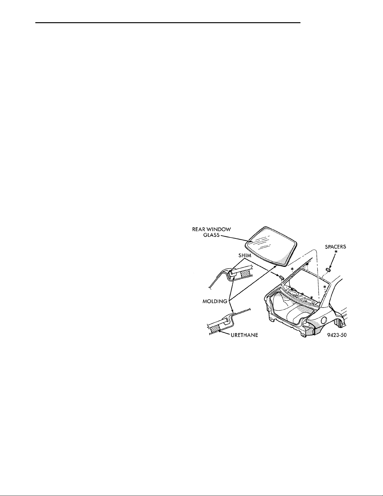
(2) Place fence spacers at the locations shown (Fig.
8).
(3) Install the rear window molding on glass.
(4) Apply a 10 mm (0.4 in.) bead of urethane
around the perimeter of the glass.
(5) Install the glass in the same manner described
in the Windshield section of this group (Fig. 8).
(6) Connect rear window defogger wiring and interior trim.
(7) After urethane has cured, water test rear window to verify repair. Verify rear window defogger
operation, see Group 8N, Rear Window Defogger.
REAR WINDOW REMOVAL
(1) Remove rear window moldings.
(2) Remove upper quarter trim panel.
(3) Disengage wire connectors from rear window
defogger.
WARNING: WEAR EYE AND HAND PROTECTION
WHEN HANDLING SAFETY GLASS. PERSONAL
INJURY CAN RESULT.
Fig. 8 Rear Window Glass
Page 8
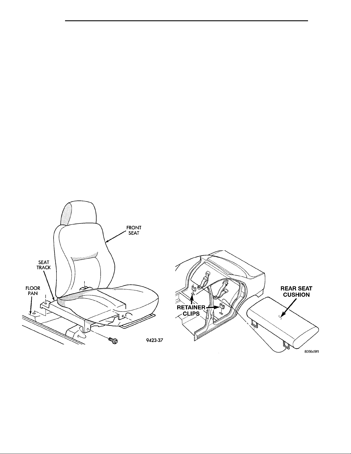
FLOOR PANSEAT TRACK FRONT SEAT
REAR SEAT CUSHIONRETAINERCLIPS
23 - 8 BODY PL
SEATS
INDEX
page page
REMOVAL AND INSTALLATION
CHILD RESTRAINT SEAT BACK ............ 9
CHILD SEAT MODULE ................... 10
REMOVAL AND INSTALLATION
FRONT SEAT
REMOVAL
(1) Move seat to forward position.
(2) Remove bolts holding rear of seat track to floor.
(3) Move seat to rearward position.
(4) Remove bolts holding front of seat track to floor
crossmember (Fig. 1).
(5) Separate seat from vehicle.
FRONT SEAT ........................... 8
REAR SEAT BACK ....................... 9
REAR SEAT CUSHION ................... 8
(4) Install and tighten front inboard bolt holding
seat track to floor crossmember.
(5) Install and tighten front outboard bolt holding
seat track to floor crossmember.
(6) Move seat to forward position.
(7) Install and tighten bolts holding rear of seat
track to floor.
NOTE: The torque specification for all front seat
retaining bolts is 55 N·M (40 ft. lbs.).
REAR SEAT CUSHION
REMOVAL
(1) Pull upward at each end of the rear seat cushion to disengage retainer loops from cups in floor.
(2) Separate rear seat cushion from vehicle (Fig.
2).
Fig. 1 Front Seat
INSTALLATION
(1) Move seat to full rearward position and verify
that both seat tracks are locked into position.
(2) Move seat into position in vehicle. Do not use
the head restraint, side shield, recliner handle, or the
adjuster lift bar to move the seat.
(3) Ensure that the locating tabs on the front
mounting feet are installed through the slits in the
carpet and into the openings in the floor pan crossmember.
Fig. 2 Rear Seat Cushion
INSTALLATION
(1) Place rear seat cushion in position under bot-
tom of seat back.
(2) Position inboard seat belts on top of seat cush-
ion.
(3) Guide seat cushion loops into retainer cups in
floor pan.
(4) Push downward on the front corners of the seat
cushion to engage retainers.
Page 9
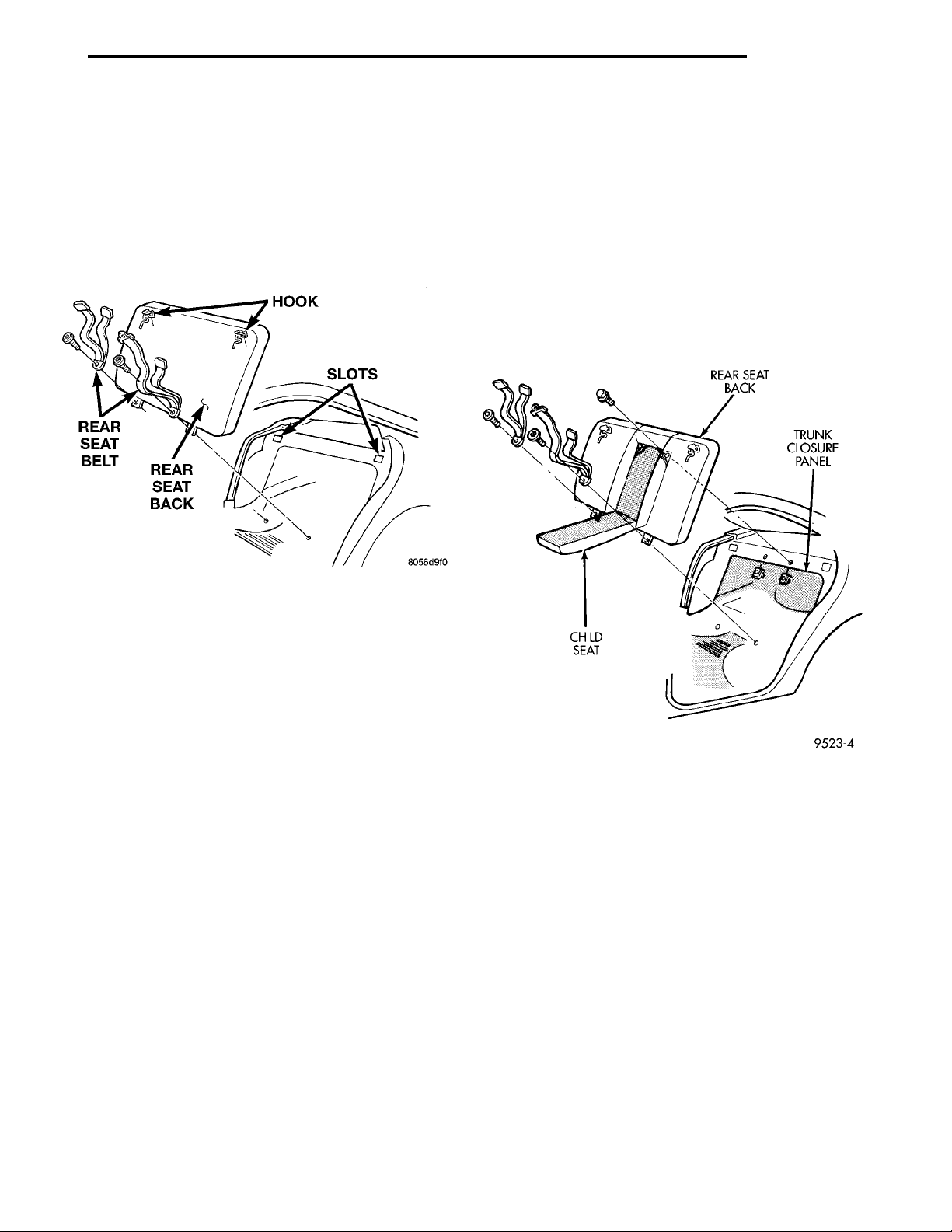
HOOK SLOTSREAR SEAT BACKREAR SEAT BELT
REAR SEAT BACKTRUNK CLOSURE PANELCHILD SEAT
PL BODY 23 - 9
REMOVAL AND INSTALLATION (Continued)
REAR SEAT BACK
REMOVAL
(1) Remove rear seat cushion.
(2) Remove bolts holding rear seat back and seat
belts to floor.
(3) Push rear seat back upward to disengage hooks
at top of seat back (Fig. 3).
(4) Separate rear seat from vehicle.
CHILD RESTRAINT SEAT BACK
REMOVAL
(1) Remove rear seat cushion.
(2) Open child seat and remove lining.
(3) Remove bolts holding seat back frame to trunk
closure panel through access holes in child seat module (Fig. 4).
(4) Remove bolts holding bottom of rear seat back
and seat belts to floor.
(5) Lift seat back upward to disengage retainer
hooks from trunk closure panel.
(6) Separate rear seat back from vehicle.
Fig. 3 Rear Seat Back
INSTALLATION
(1) Move rear seat back into position in vehicle.
(2) Push seat back downward to engage hooks at
top of seat back.
(3) Install bolts holding rear seat back and seat
belts to floor.
NOTE: The torque specification for the inner seat
belt/rear seat back retaining bolts is 57 N·M (42 ft.
lbs.).
(4) Install rear seat cushion.
Fig. 4 Child Restraint Seat Back
INSTALLATION
(1) Move child restraint seat back into position in
vehicle.
(2) Push seat back downward to engage hooks into
trunk closure panel.
(3) Install bolts holding bottom of rear seat back
and seat belts to floor.
(4) Install bolts holding seat back frame to trunk
closure panel through access holes in child seat module.
(5) Install child seat lining and close child seat.
(6) Install rear seat cushion.
Page 10

23 - 10 BODY PL
REMOVAL AND INSTALLATION (Continued)
CHILD SEAT MODULE
REMOVAL
(1) Remove rear seat back from vehicle.
(2) Slide lower bolster cushion retainer from chan-
nel on child seat cushion.
(3) Separate lower bolster from seat child seat.
(4) Remove liner from child seat module.
(5) Disengage push-in fasteners holding upper bol-
ster to child seat module above shoulder belts.
(6) Remove screws holding top of child seat module
to seat back frame from behind shoulder belts.
(7) Remove screws holding bottom of child seat
module to seat back frame (Fig. 5).
(8) Separate child seat module from seat back.
INSTALLATION
(1) Place child seat module in position on seat
back.
(2) Install screws to hold bottom of child seat mod-
ule to seat back frame.
CAUTION: Do not capture seat belt webbing
between module and seat back frame when installing upper screws.
(3) Install screws to hold top of child seat module
to seat back frame from behind shoulder belts.
(4) Engage push-in fasteners to hold upper bolster
to child seat module above shoulder belts.
(5) Install liner in child seat module.
(6) Place lower bolster in position on seat child
seat.
Fig. 5 Child Seat Module
(7) Slide lower bolster cushion retainer into channel on child seat cushion.
(8) Install rear seat back in vehicle.
Page 11

PL BODY 23 - 11
SUNROOF
INDEX
page page
DIAGNOSIS AND TESTING
DIAGNOSTIC PROCEDURES .............. 11
SUNROOF DIAGNOSIS .................. 11
REMOVAL AND INSTALLATION
SUNROOF CABLES ..................... 13
SUNROOF COMPONENTS ............... 14
SUNROOF DRIVE MOTOR ................ 11
SUNROOF GLASS PANEL ................ 11
DIAGNOSIS AND TESTING
DIAGNOSTIC PROCEDURES
Before beginning sunroof diagnostics verify that all
other power accessories are in proper operating condition. If not, a common electrical problem may exist.
Refer to the Wiring Diagrams section of this publication for circuit, splice and component descriptions.
Check the condition of the circuit protection (fuses,
circuit breakers or fuse links). Inspect all wiring connector pins for proper engagement and continuity.
Check for battery voltage at the power sunroof control switches. If battery voltage is detected at the
control switches, proceed with the following tests.
SUNROOF DIAGNOSIS
SUNROOF GUIDE AND MECHANISM
ASSEMBLY .......................... 13
SUNROOF MODULE .................... 11
SUNROOF PROCEDURE INFORMATION ..... 11
SUNROOF SUNSHADE .................. 13
SUNROOF WIND DEFLECTOR ............ 12
ADJUSTMENTS
SUNROOF GLASS HEIGHT ADJUSTMENT . . . 15
(3) Tighten all fasteners, starting from the front
and working rearward and then the motor bracket.
(4) Adjust glass panel for flushness to roof. Refer
to glass adjustment procedure in this section.
(5) Install headlining.
(6) Verify correct operation.
SUNROOF GLASS PANEL
REMOVAL
(1) Position sunroof sunshade (4) in full rearward
position.
(2) Remove six glass attachment screws.
(3) Push glass panel upward from underside until
glass panel clears the roof panel.
(4) Lift glass panel from vehicle.
REMOVAL AND INSTALLATION
SUNROOF PROCEDURE INFORMATION
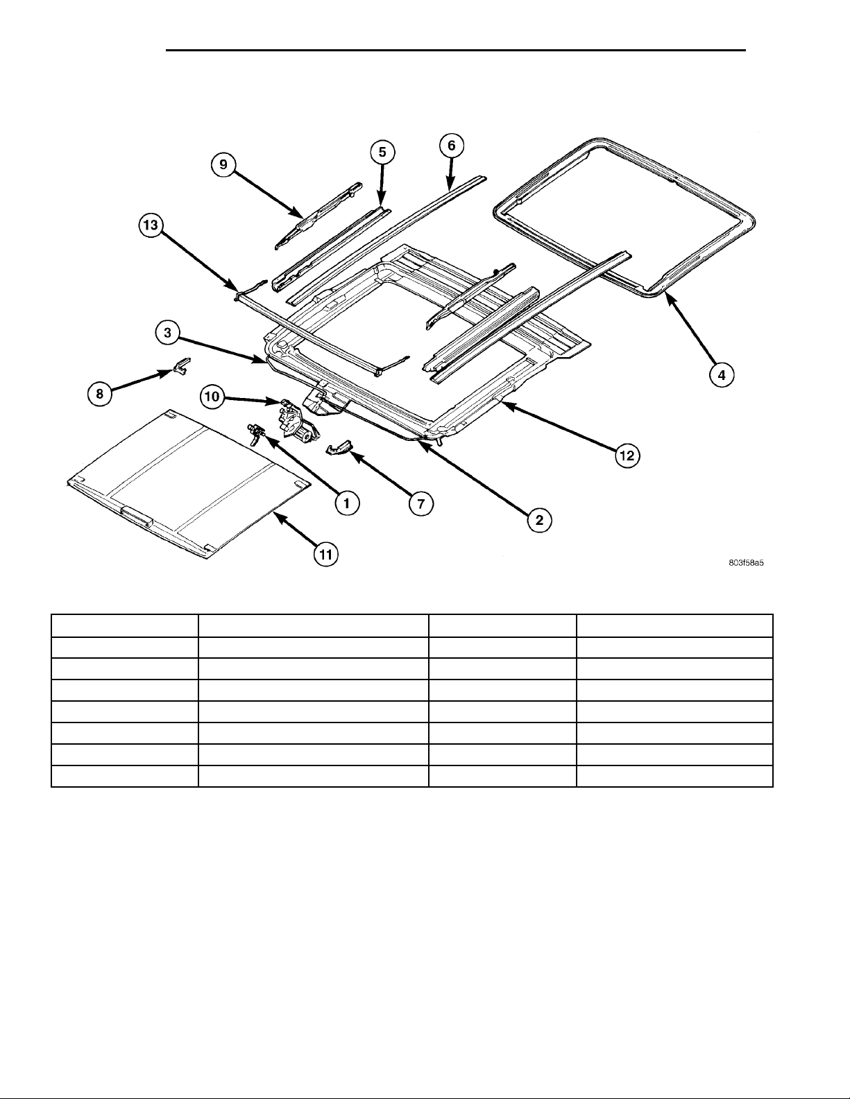
The numbered call-outs in the following service procedures refer the numbered parts
found in the figure at the end of this section.
SUNROOF MODULE
REMOVAL
(1) Remove headlining.
(2) Remove fasteners attaching sunroof module to
vehicle roof and support braces.
(3) With the aid of a helper, separate sunroof module from roof.
(4) Remove sunroof module from vehicle.
INSTALLATION
(1) With the aid of a helper, position sunroof module in vehicle.
(2) Install fasteners holding sunroof module to
vehicle roof.
INSTALLATION
(1) Position glass panel (4) in opening in vehicle
roof.
(2) Install, but do not tighten, glass attachment
screws.
(3) With the aid of a helper, hold the glass panel in
position and tighten glass attachment screws.
(4) Verify the correct glass height. Refer to Glass
Height Adjustment procedure in this section.
SUNROOF DRIVE MOTOR
CAUTION: Do not cycle the sunroof drive motor
prior to installation. The drive motor is shipped in
the closed position. The sunroof vent position is
programmed into the drive motor and is dependent
upon the drive motor closed position. If the drive
motor and the sunroof mechanism are not both in
the closed position, the sunroof vent height will not
be correct.
Page 12
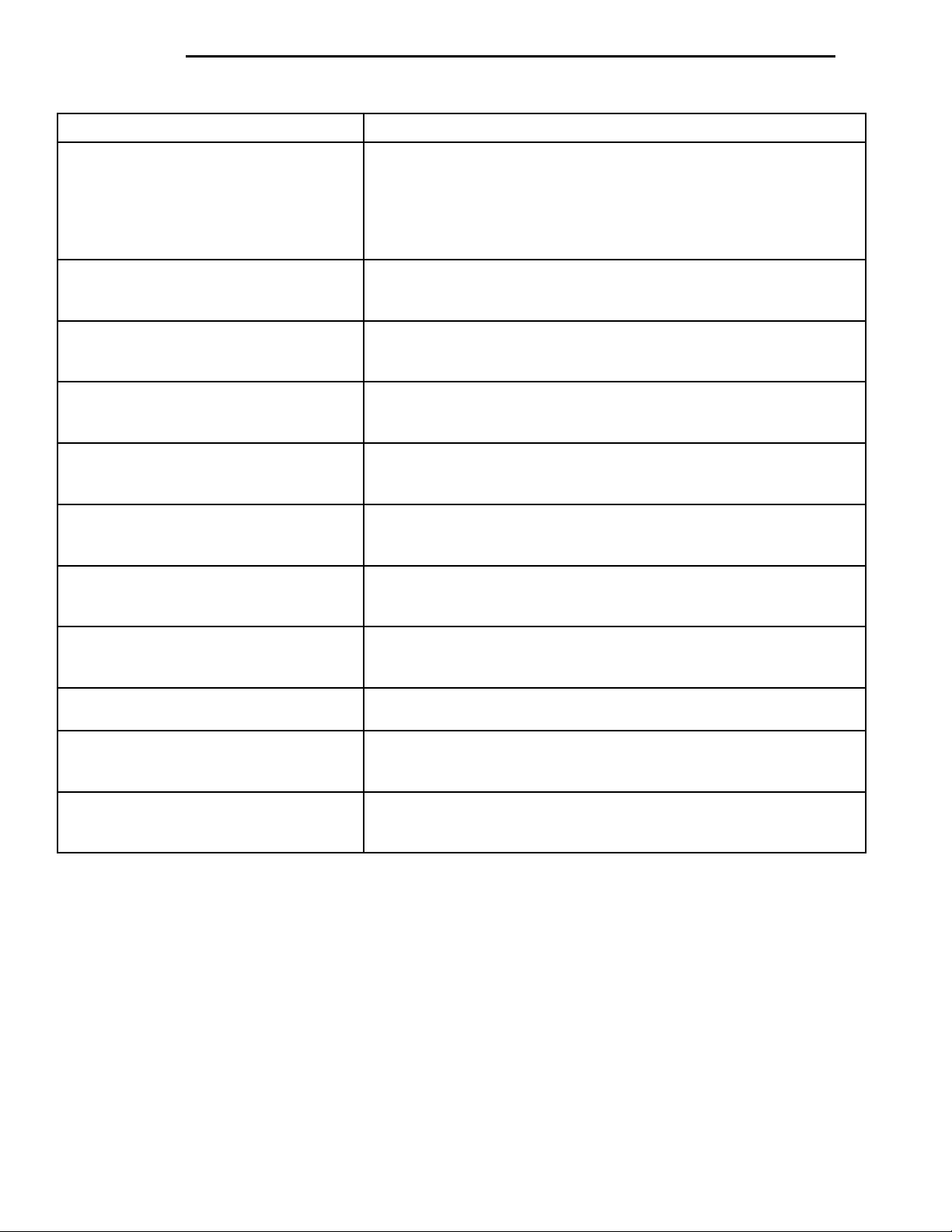
23 - 12 BODY PL
REMOVAL AND INSTALLATION (Continued)
SYMPTOM POSSIBLE CAUSE
Sunroof motor inoperative. • Contaminated or corroded slides and channels.
• Binding cable or linkage.
• Faulty circuit ground.
• Faulty power circuit to sunroof drive motor.
• Faulty sunroof drive motor.
• Faulty sunroof motor connector.
Audible whine when switch is depressed,
sunroof does not operate.
Sunroof opens, but does not close. • Binding linkage.
Sunroof vents, but does not open. • Binding linkage.
Sunroof does not vent • Binding cable.
Sunroof vents and opens but does not
close
Sunroof water leak. • Drain tubes clogged or kinked.
Wind noise from sunroof. • Front of glass panel too high or rear too low.
Glass panel hangs up or snaps between
vent and open.
Rattles from open sunroof while driving • Loose attaching hardware.
Rattles from closed sunroof while driving • Loose attaching hardware.
• Faulty motor drive clutch.
• Binding linkage.
• Faulty sunroof motor connections.
• Faulty circuit.
• Faulty switch.
• Faulty circuit.
• Faulty switch.
• Faulty circuit.
• Faulty switch.
• Binding linkage.
• Faulty circuit.
• Faulty switch.
• Glass panel improperly adjusted.
• Faulty glass panel seal.
• Glass panel not centered in opening.
• Faulty glass panel seal.
• Glass panel improperly adjusted.
• Glass panel seal has inconsistent compression.
• Weak springs on wind deflector.
• Sunshade out of the track.
• Wind deflector contacting glass panel or drain trough.
• Sunshade out of the track.
REMOVAL
(1) Remove headlining until the sunroof drive
motor (10) can be accessed.
(2) If the drive motor is to be reused, cycle the
sunroof to the full forward position.
(3) Disconnect wire harness connector from motor.
(4) Remove the three screws attaching drive motor
to sunroof module bracket.
(5) Separate drive motor (10) from bracket.
INSTALLATION
(1) With the aid of a helper, hold the sunroof glass
panel in the closed position and engage the drive
motor (10) into the sunroof drive cables.
(2) Install screws holding drive motor to bracket.
(3) Connect wire harness to drive motor.
(4) Install headlining.
SUNROOF WIND DEFLECTOR
REMOVAL
(1) Open sunroof to full open position.
(2) Pull one end of wind deflector flap out of the
wind deflector beam (13).
(3) Release corner piece locking tab and separate
corner piece from wind deflector beam.
(4) Rotate corner piece outboard to release tab
from roof flange.
(5) Rotate corner piece to a vertical position and
pull it up through hole in guide (5).
(6) Repeat for other corner piece.
Page 13
PL BODY 23 - 13
REMOVAL AND INSTALLATION (Continued)
INSTALLATION
(1) Hold corner piece vertically and push tab down
through hole in guide (5).
(2) Rotate corner piece inward and place tab under
roof flange.
(3) Connect corner piece to wind deflector beam
(13).
(4) Install wind deflector flap into wind deflector
beam.
(5) Repeat for other corner piece.
SUNROOF SUNSHADE
REMOVAL
(1) Remove sunroof glass panel (4). Refer to procedure found in this section.
(2) Slide sunshade (11) to full forward position.
(3) Disengage slide blocks on one side of sunshade
from sunshade guide (6).
(4) Lift and pull sunshade out of opposite sunshade guide.
INSTALLATION
(1) Place sunshade with cloth side down and
install one side’s slide blocks into the track on the
sunshade guide (6).
(2) Slide the other side’s slide blocks to fully
inward position and insert them into the sunshade
guide (6).
(3) Verify that all four slide blocks are fully
engaged in the sunshade guide (6).
(4) Slide sunshade (11) fully rearward.
(5) Install sunroof glass panel (4). Refer to procedure found in this section.
SUNROOF GUIDE AND MECHANISM ASSEMBLY
(5) Install sunroof glass panel. Refer to procedure
found in this section.
SUNROOF CABLES
REMOVAL
(1) Remove sunroof glass panel (4). Refer to proce-
dure found in this section.
(2) Cycle the sunroof mechanism to the full for-
ward position.
CAUTION: Do not remove sunroof drive motor
unless sunroof mechanism is in the full forward
position.
(3) Remove sunroof drive motor (10). Refer to pro-
cedure found in this section.
(4) Remove front locator (7 or 8) for appropriate
sunroof cable.
(5) Disengage sunroof cable from sunroof mecha-
nism (9).
(6) Pull sunroof cable from drive tube (2 or 3).
INSTALLATION
(1) Push sunroof cable through drive tube (2 or 3).
(2) Engage sunroof cable into sunroof mechanism
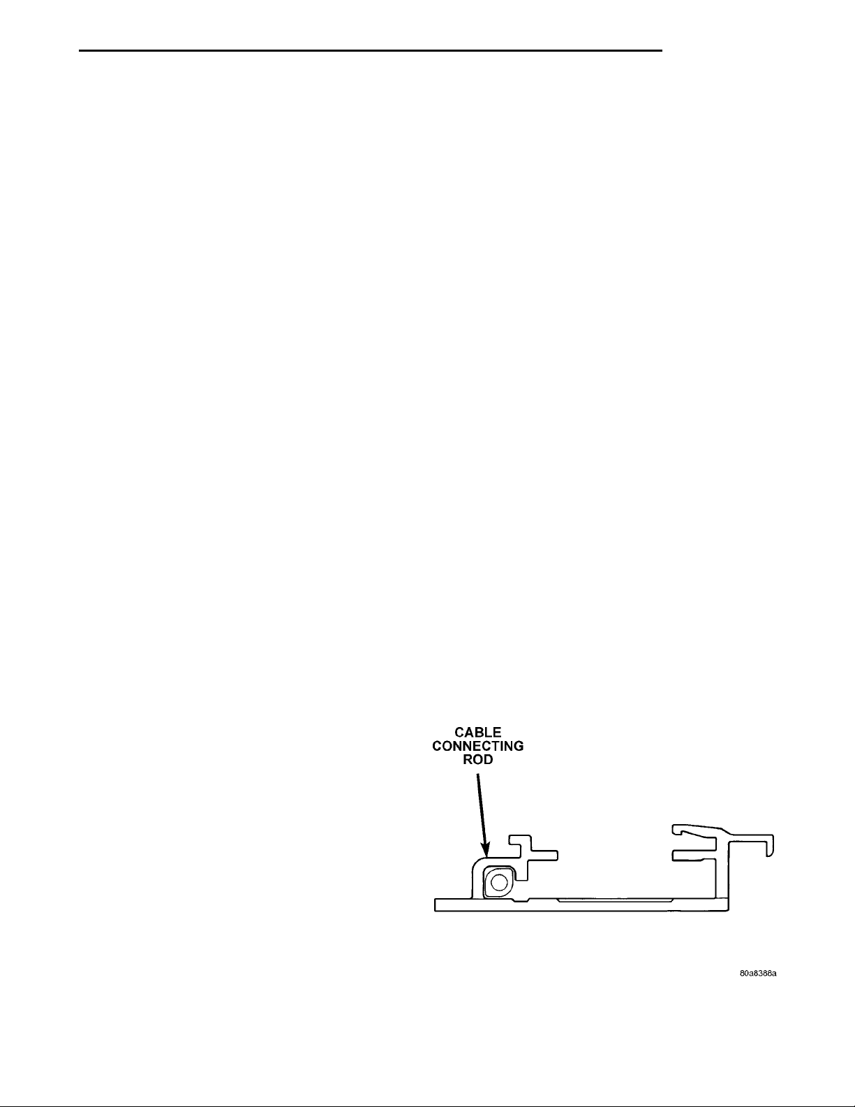
(9) making sure cable connecting rod is rotated at a
45 degree angle towards inside of vehicle (Fig. 1).
(3) Install front locator (7 or 8) over sunroof cable.
Moving the sunroof mechanism rearward slightly will
CABLE CONNECTING ROD
ease locator installation.
(4) Move sunroof to full forward position.
(5) Install sunroof drive motor (10).
(6) Install sunroof glass panel (5). Refer to procedure found in this section.
REMOVAL
(1) Remove sunroof glass panel (4). Refer to proce-
dure in this section.
(2) Remove front locator (7 or 8).
(3) Disengage cable from mechanism (9).
(4) Remove screws holding sunroof guide (5) and
mechanism (9) assembly to sunroof module.
(5) Lift assembly from module.
(6) Rotate assembly to disengage wind deflector
(13) from assembly.
INSTALLATION
(1) Engage wind deflector (13) into guide (5) and
mechanism (9) assembly.
(2) Position assembly onto module and install
screws holding assembly to sunroof module.
(3) Engage drive cable to mechanism.
(4) Install front locator (7 or 8 ). It may ease
installation to move sunroof mechanism slightly rearward.
Fig. 1 Front View of Guide
Page 14
23 - 14 BODY PL
REMOVAL AND INSTALLATION (Continued)
SUNROOF COMPONENTS
Fig. 2 Sunroof Components
Item Number Component Name Item Number Component Name
1 Drive Tube Locator 8 Locator R.H.
2 Drive Tube L.H. 9 Mechanism
3 Drive Tube R.H. 10 Drive Motor
4 Glass Reinforcment Panel 11 Sunshade
5 Guide 12 Tray Assembly
6 Sunshade Guide 13 Wind Deflector
7 Locator L.H.
Page 15

PL BODY 23 - 15
ADJUSTMENTS
SUNROOF GLASS HEIGHT ADJUSTMENT
FLUSHNESS
(1) Position sunshade in full rearward position.
(2) To adjust front of glass;
(a) Loosen front and middle glass attachment
screws
(b) Adjust front of sunroof glass panel so that
the corners are flush to 1.0 mm below the top surface of the roof panel.
(c) Tighten all glass attachment screws.
(3) To adjust rear of glass;
(a) Loosen rear and middle glass attachment
screws
(b) Adjust rear of sunroof glass panel so that the
corners are flush to 6 1.0 mm off the top surface of
the roof panel.
(c) Tighten all glass attachment screws.
VENT HEIGHT
(1) Cycle the sunroof module to vent position using
the drive motor.
(2) Check glass height in tilt using the appropriate
measuring tool.
(3) If the vent height is greater than 35 mm, using
switch slowly set to correct height.
(4) After setting correct height, remove drive
motor.
(5) With the motor removed, use the switch to set
tilt by operating the gear to the full closed position.
(6) Using tilt switch only, operate the motor until
it comes to a full stop at tilt position.
(7) Install drive motor and verify correct operation.
Page 16

23 - 16 BODY PL
BODY COMPONENTS
INDEX
page page
DIAGNOSIS AND TESTING
WATER LEAKS ........................ 17
WIND NOISE .......................... 18
REMOVAL AND INSTALLATION
WINDOW REGULATOR—4 DOOR .......... 25
A-PILLAR TRIM ........................ 37
B-PILLAR APPLIQUE—2 DOOR ............ 32
B-PILLAR APPLIQUE—4 DOOR ............ 32
B-PILLAR TRIM—4 DOOR ................ 38
B-PILLAR WEATHERSTRIP CHANNEL ....... 33
BODY VENT ........................... 43
CARPET ............................. 41
COWL COVER ......................... 20
DOOR HINGE ......................... 30
DOOR LOCK CYLINDER ................. 27
DOOR OPENING TRIM WELT ............. 37
DOOR SILL TRIM ....................... 36
DOOR ............................... 30
FLOOR CONSOLE ...................... 36
FRONT DOOR CHECK STOP .............. 28
FRONT DOOR GLASS—2 DOOR ........... 23
FRONT DOOR GLASS—4 DOOR ........... 24
FRONT DOOR INNER BELT
WEATHERSTRIP ...................... 22
FRONT DOOR LATCH STRIKER ........... 31
FRONT DOOR LATCH ................... 26
FRONT DOOR OUTER BELT
WEATHERSTRIP ...................... 29
FRONT DOOR OUTSIDE HANDLE .......... 27
FRONT DOOR TRIM—2 DOOR ............ 20
FRONT DOOR TRIM—4 DOOR ............ 21
FRONT DOOR WATER SHIELD ............ 22
FRONT DOOR WEATHERSTRIP ........... 31
FRONT OUTBOARD SEAT BELT ........... 40
FRONT SEAT BELT BUCKLE .............. 40
FRONT SEAT BELT RETRACTOR .......... 40
FRONT SHOULDER BELTADJUSTER ....... 41
FRONT VERTICAL GUIDE BAR ............ 26
GRILLE .............................. 18
HEADLINING .......................... 42
HOOD HINGE ......................... 19
HOOD LATCH ......................... 18
HOOD RELEASE CABLE ................. 19
HOOD ............................... 19
LOCK BUTTON BELL-CRANK ............. 22
LOWER QUARTER TRIM—4 DOOR ......... 39
PARCEL SHELF TRIM ................... 39
QUARTER TRIM PANEL—2 DOOR ......... 38
REAR DOOR GLASS .................... 34
REAR DOOR INNER BELT WEATHERSTRIP . . 34
REAR DOOR INTERLOCK LATCH STRIKER . . 36
REAR DOOR LATCH STRIKER ............ 35
REAR DOOR LATCH .................... 35
REAR DOOR LOCK BELL CRANK .......... 35
REAR DOOR OUTER BELT
WEATHERSTRIP ...................... 35
REAR DOOR TRIM ..................... 33
REAR DOOR WINDOW REGULATOR ....... 34
REAR SEAT BELT BUCKLE ............... 41
REAR SEAT BELT RETRACTOR ........... 41
REAR SPOILER ........................ 45
REAR VERTICAL GUIDE BAR ............. 26
ROOF APERTURE (RAP) MOLDING ........ 46
ROOF RACK CROSS RAILS .............. 47
ROOF RACK .......................... 46
ROOF RAIL WEATHERSTRIP .............. 31
ROOF RAIL WEATHERSTRIP .............. 32
SIDE COWL TRIM ...................... 37
SIDE VIEW MIRROR STANCHION .......... 29
SIDE VIEW MIRROR TRIM COVER ......... 28
SIDE VIEW MIRROR .................... 28
TRUNK CARPET ....................... 45
TRUNK LATCH STRIKER ................. 44
TRUNK LATCH ......................... 44
TRUNK LID LIFT SPRINGS ............... 43
TRUNK LID ........................... 43
TRUNK LOCK CYLINDER ................ 44
TRUNK TRIM PANEL .................... 45
TRUNK WEATHERSTRIP ................. 44
UPPER QUARTER TRIM—4 DOOR ......... 39
WINDOW INNERBELT STABILIZER ......... 22
WINDOW REGULATOR—2 DOOR .......... 24
ADJUSTMENTS
FRONT DOOR GLASS ADJUSTMENT ....... 47
FRONT DOOR LATCH ADJUSTMENT ....... 48
REAR DOOR GLASS ADJUSTMENT ........ 48
REAR DOOR LATCH ADJUSTMENT ........ 49
SPECIFICATIONS
BODY LUBRICATION SPECIFICATIONS ...... 49
SPECIAL TOOLS
BODY ............................... 50
Page 17

PL BODY 23 - 17
DIAGNOSIS AND TESTING
WATER LEAKS
Water leaks can be caused by poor sealing,
improper body component alignment, body seam
porosity, missing plugs, or blocked drain holes. Centrifugal and gravitational force can cause water to
drip from a location away from the actual leak point,
making leak detection difficult. All body sealing
points should be water tight in normal wet-driving
conditions. Water flowing downward from the front of
the vehicle should not enter the passenger or luggage
compartment. Moving sealing surfaces will not
always seal water tight under all conditions. At
times, side glass or door seals will allow water to
enter the passenger compartment during high pressure washing or hard driving rain (severe) conditions. Overcompensating on door or glass
adjustments to stop a water leak that occurs under
severe conditions can cause premature seal wear and
excessive closing or latching effort. After completing
a repair, water-test vehicle to verify leak has stopped
before returning vehicle to use.
VISUAL INSPECTION BEFORE WATER LEAK TESTS
Verify that floor and body plugs are in place, body
drains are clear, and body components are properly
aligned and sealed. If component alignment or sealing is necessary, refer to the appropriate section of
this group for proper procedures.
WATER LEAK TESTS
WARNING: DO NOT USE ELECTRIC SHOP LIGHTS
OR TOOLS IN WATER TEST AREA. PERSONAL
INJURY CAN RESULT.
When the conditions causing a water leak have
been determined, simulate the conditions as closely
as possible.
• If a leak occurs with the vehicle parked in a
steady light rain, flood the leak area with an openended garden hose.
• If a leak occurs while driving at highway speeds
in a steady rain, test the leak area with a reasonable
velocity stream or fan spray of water. Direct the
spray in a direction comparable to actual conditions.
• If a leak occurs when the vehicle is parked on an
incline, hoist the end or side of the vehicle to simulate this condition. This method can be used when
the leak occurs when the vehicle accelerates, stops or
turns. If the leak occurs on acceleration, hoist the
front of the vehicle. If the leak occurs when braking,
hoist the back of the vehicle. If the leak occurs on left
turns, hoist the left side of the vehicle. If the leak
occurs on right turns, hoist the right side of the vehi-
cle. For hoisting recommendations refer to Group 0,
Lubrication and Maintenance, General Information
section.
WATER LEAK DETECTION
To detect a water leak point-of-entry, do a water
test and watch for water tracks or droplets forming
on the inside of the vehicle. If necessary, remove interior trim covers or panels to gain visual access to the
leak area. If the hose cannot be positioned without
being held, have someone help do the water test.
Some water leaks must be tested for a considerable
length of time to become apparent. When a leak
appears, find the highest point of the water track or
drop. The highest point usually will show the point of
entry. After leak point has been found, repair the
leak and water test to verify that the leak has
stopped.
Locating the entry point of water that is leaking
into a cavity between panels can be difficult. The
trapped water may splash or run from the cavity,
often at a distance from the entry point. Most water
leaks of this type become apparent after accelerating,
stopping, turning, or when on an incline.
MIRROR INSPECTION METHOD
When a leak point area is visually obstructed, use
a suitable mirror to gain visual access. A mirror can
also be used to deflect light to a limited-access area
to assist in locating a leak point.
BRIGHT LIGHT LEAK TEST METHOD
Some water leaks in the luggage compartment can
be detected without water testing. Position the vehicle in a brightly lit area. From inside the darkened
luggage compartment inspect around seals and body
seams. If necessary, have a helper direct a drop light
over the suspected leak areas around the luggage
compartment. If light is visible through a normally
sealed location, water could enter through the opening.
PRESSURIZED LEAK TEST METHOD
When a water leak into the passenger compartment cannot be detected by water testing, pressurize
the passenger compartment and soap test exterior of
the vehicle. To pressurize the passenger compartment, close all doors and windows, start engine, and
set heater control to high blower in HEAT position. If
engine can not be started, connect a charger to the
battery to ensure adequate voltage to the blower.
With interior pressurized, apply dish detergent solution to suspected leak area on the exterior of the
vehicle. Apply detergent solution with spray device or
soft bristle brush. If soap bubbles occur at a body
seam, joint, seal or gasket, the leak entry point could
be at that location.
Page 18
HOODLATCH GRILLERADIATOR CLOSURE PANEL
RADIATOR CLOSURE PANELPARK AND TURN SIGNALLAMPSCREWSGRILLE
23 - 18 BODY PL
DIAGNOSIS AND TESTING (Continued)
WIND NOISE
Wind noise is the result of most air leaks. Air leaks
can be caused by poor sealing, improper body component alignment, body seam porosity, or missing plugs
in the engine compartment or door hinge pillar areas.
All body sealing points should be airtight in normal
driving conditions. Moving sealing surfaces will not
always seal airtight under all conditions. At times,
side glass or door seals will allow wind noise to be
noticed in the passenger compartment during high
crosswinds. Over compensating on door or glass
adjustments to stop wind noise that occurs under
severe conditions can cause premature seal wear and
excessive closing or latching effort. After a repair procedure has been performed, test vehicle to verify
noise has stopped before returning vehicle to use.
Wind noise can also be caused by improperly fitted
exterior moldings or body ornamentation. Loose
moldings can flutter, creating a buzzing or chattering
noise. An open cavity or protruding edge can create a
whistling or howling noise. Inspect the exterior of the
vehicle to verify that these conditions do not exist.
VISUAL INSPECTION BEFORE TESTS
Verify that floor and body plugs are in place and
body components are aligned and sealed. If component alignment or sealing is necessary, refer to the
appropriate section of this group for proper procedures.
ROAD TESTING WIND NOISE
(1) Drive the vehicle to verify the general location
of the wind noise.
(2) Apply 50 mm (2 in.) masking tape in 150 mm
(6 in.) lengths along weatherstrips, weld seams or
moldings. After each length is applied, drive the vehicle. If noise goes away after a piece of tape is applied,
remove tape, locate, and repair defect.
POSSIBLE CAUSE OF WIND NOISE
• Moldings standing away from body surface can
catch wind and whistle.
• Gaps in sealed areas behind overhanging body
flanges can cause wind-rushing sounds.
• Misaligned movable components.
• Missing or improperly installed plugs in pillars.
• Weld burn through holes.
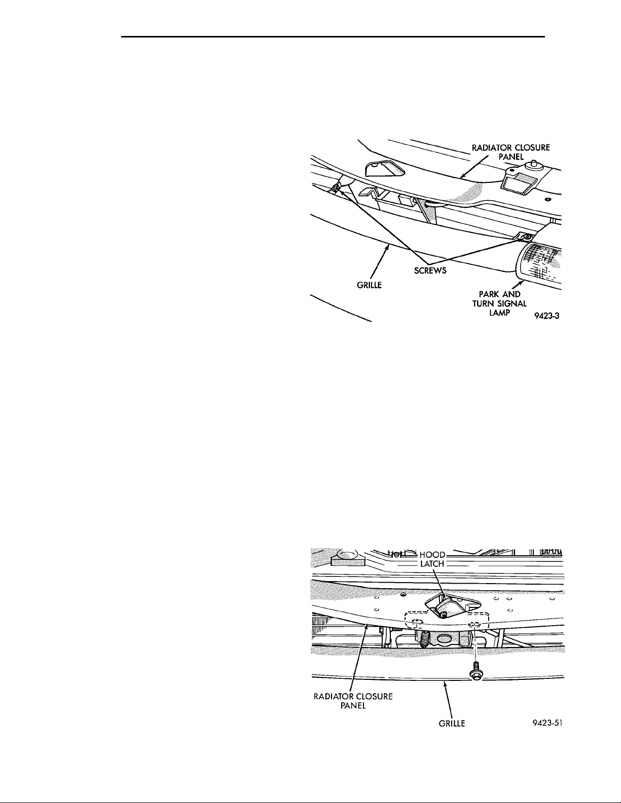
(2) Remove screws holding grille to parking lamps
(Fig. 1).
(3) Remove screw holding grille to radiator closure
panel.
(4) Separate grille from vehicle.
Fig. 1 Grille
INSTALLATION
(1) Place grille into position on vehicle.
(2) Install screw holding grille to radiator closure
panel.
(3) Install screws holding grille to parking lamps.
HOOD LATCH
REMOVAL
(1) Release hood latch and open hood.
(2) Support hood on prop rod.
(3) Remove grille.
(4) Remove screws holding hood latch to radiator
closure panel (Fig. 2).
(5) Separate hood latch from closure panel.
(6) Disengage remote release cable from latch.
REMOVAL AND INSTALLATION
GRILLE
REMOVAL
(1) Release hood latch, open and support hood on
prop rod.
Fig. 2 Hood Latch
Page 19
HOODRELEASEHANDLE
LEFT
COWL
PL BODY 23 - 19
REMOVAL AND INSTALLATION (Continued)
INSTALLATION
(1) Engage remote release cable into latch.
(2) Place hood latch onto radiator closure panel.
(3) Install bolts holding latch to closure panel.
(4) Install grille.
(5) Close hood and verify alignment of hood and
that latch is securely engaged.
HOOD RELEASE CABLE
REMOVAL
(1) Disconnect remote hood release cable from
hood latch.
(2) Remove left front cowl trim panel.
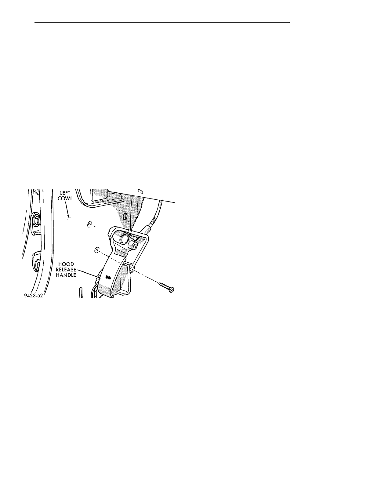
(3) Remove screws holding hood release handle to
cowl panel (Fig. 3).
(4) Disengage rubber grommet from dash panel
behind instrument panel.
(5) Pull release cable through hole in dash panel.
(6) Separate cable and handle from vehicle.
hood, align all marks and secure bolts. The hood
should be aligned to 4 mm (0.160 in.) gap to the front
fenders and flush across the top surfaces along fenders.
(4) Remove the top bolts holding hood to hinge and
loosen the bottom bolts until they can be removed by
hand.
(5) With assistance from a helper at the opposite
side of the vehicle to support the hood, remove bottom bolts holding hood to hinge.
(6) Separate the hood from the vehicle.
INSTALLATION
(1) Place hood in position on vehicle. With assistance from a helper at the opposite side of the vehicle
to support the hood, install bottom bolts to hold hood
to hinge finger tight.
(2) Install top bolts to hold hood to hinge finger
tight.
(3) Position bolts at marks and tighten bolts. The
hood should be aligned to 4 mm (0.160 in.) gap to the
front fenders and flush across the top surfaces along
fenders.
(4) Engage under hood lamp wire connector to
engine compartment wire harness.
(5) Verify hood operation and alignment.
Fig. 3 Hood Release Cable
INSTALLATION
(1) Assemble cable and handle onto vehicle.
(2) Push release cable through hole in dash panel.
(3) Engage rubber grommet into dash panel.
(4) Install screws holding hood release handle to
cowl panel.
(5) Install left front cowl trim panel.
(6) Connect remote hood release cable to hood
latch.
(7) Close hood and verify operation.
HOOD
REMOVAL
(1) Raise hood to full up position.
(2) Disengage under hood lamp wire connector
from engine compartment wire harness.
(3) Mark all bolt and hinge attachment locations
with a grease pencil or other suitable device to provide reference marks for installation. When installing
HOOD HINGE
REMOVAL
(1) Support hood on the side that requires hinge
replacement.
(2) Mark all bolt and hinge attachment locations
with a grease pencil or other suitable device to provide reference marks for installation. When installing
hood hinge, align all marks and secure bolts. The
hood should be aligned to 4 mm (0.160 in.) gap to the
front fenders and flush across the top surfaces along
fenders. Shims can be added or removed under hood
hinge to achieve proper hood height.
(3) Remove bolts holding hood to hinge.
(4) Remove bolts holding hood hinge to front
fender flange and separate hinge from vehicle. If necessary, paint new hinge before installation.
INSTALLATION
(1) If necessary, paint new hinge before installation.
(2) Place hinge in position on vehicle.
(3) Install bolts to hold hood hinge to front fender
flange.
(4) Install bolts to hold hood to hinge.
(5) Align all marks and secure bolts. The hood
should be aligned to 4 mm (0.160 in.) gap to the front
fenders and flush across the top surfaces along fenders. Shims can be added or removed under hood
hinge to achieve proper hood height.
(6) Remove support from under hood and verify
hood operation.
Page 20
COWLCOVER PUSH-IN FASTENERCOWL
23 - 20 BODY PL
REMOVAL AND INSTALLATION (Continued)
COWL COVER
REMOVAL
(1) Release hood latch and open hood.
(2) Remove windshield wiper arms, refer to Group
8K, Windshield Wiper and Washer Systems for
proper procedures.
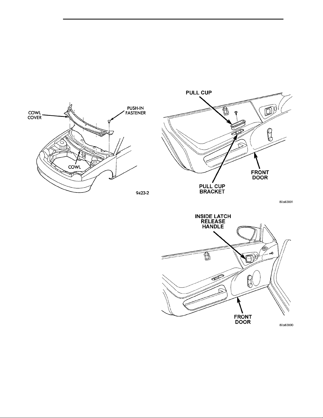
(3) Remove push-in fasteners holding cowl cover to
cowl at base of windshield opening (Fig. 4).
(4) Separate cowl cover from vehicle.
(11) Separate latch rod from handle.
CAUTION: Do not allow door trim panel to hang by
the wire connector or wiring.
(12) Disengage wire connector from power door
lock switch, mirror switch, and power window switch,
if so equipped.
(13) Separate trim panel from vehicle.
Fig. 4 Cowl Cover
INSTALLATION
(1) Place cowl panel in place on vehicle.
(2) Install push-in fasteners holding cowl panel to
cowl at base of windshield opening.
(3) Install windshield wiper arms, refer to Group
8K, Windshield Wiper and Washer Systems, for
proper procedures.
FRONT DOOR TRIM—2 DOOR
REMOVAL
(1) Release door latch and open door.
(2) Lower door glass.
(3) Remove screw inside pull cup holding door trim
panel to bracket (Fig. 5).
(4) Pull and hold inside latch release handle away
from door trim.
(5) Remove screw holding trim panel to door from
behind inside door handle (Fig. 6).
(6) Remove window regulator crank, if so
equipped.
(7) Disengage hidden clips holding trim panel to
door from around perimeter of trim panel (Fig. 7).
(8) Tilt trim panel outward to clear locator pins on
backside of trim panel.
(9) Disengage trim panel from retainer channel on
inner belt weatherstrip at the top of the door by lifting and gently jiggling.
(10) Move trim panel away from door and disengage clip holding door latch linkage to back of inside
door handle.
Fig. 5 Front Door Pull Cup
Fig. 6 Inside Door Handle Screw
INSTALLATION
(1) Replace any damaged or missing push–in fas-
teners from around perimeter of door trim panel.
(2) Place trim panel near door.
(3) Engage wire connector to power lock switch,
mirror switch, and power window switch, if so
equipped.
(4) Insert latch rod into inside latch release.
Page 21
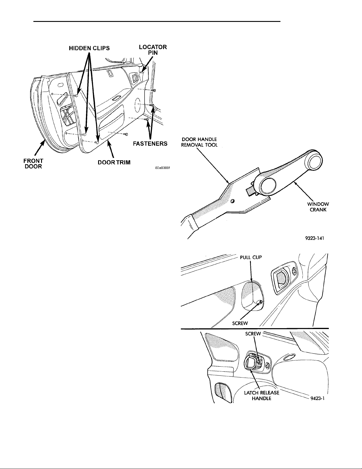
HIDDEN CLIPSLOCATOR PINFASTENERSDOOR TRIMFRONT DOOR
PL BODY 23 - 21
REMOVAL AND INSTALLATION (Continued)
(9) Disengage trim panel from retainer channel in
inner belt weatherstrip at top of door by lifting while
gently jiggling.
(10) Move trim panel away from door and disengage clip holding latch rod to handle.
(11) Separate latch rod from handle.
CAUTION: Do not allow door trim panel to hang by
the wire connector or wiring.
(12) Disengage wire connector from power door
lock switch, mirror switch, and power window switch
if so equipped.
(13) Separate trim panel from door.
Fig. 7 Door Trim Panel
(5) Engage clip holding door latch linkage to back
of inside door handle.
(6) Engage trim panel into retainer channel at top
of door and push down to seat.
(7) Locate door trim panel to inner door panel by
aligning locating pins on backside of trim panel to
mating holes in inner door panel. Gently shift panel
forward or rearward if necessary.
(8) Engage hidden clips holding trim panel to door
from around perimeter of trim panel.
(9) With the window in the down position, orientate the window regulator crank handle appropriately. Install the right handle at the 10 o’clock
position and the left handle at the 2 o’clock position,
if so equipped.
(10) Install screw holding trim panel to door from
behind inside door handle.
(11) Install screw inside pull cup holding door trim
panel to bracket.
Fig. 8 Window Crank
PULL CUPSCREWSCREWLATCH RELEASE HANDLE
FRONT DOOR TRIM—4 DOOR
REMOVAL
(1) Release door latch and open door.
(2) Lower door glass.
(3) Remove window regulator crank, if so equipped
(Fig. 8).
(4) Remove screw from inside arm rest pull cup
(Fig. 9).
(5) Pull and hold inside latch release handle away
from door trim.
(6) Remove screw from behind inside latch release
handle (Fig. 9).
(7) Disengage push-in fasteners holding trim to
door panel around perimeter of trim panel.
(8) Tilt trim panel outward to clear locator pins on
backside of trim panel.
Fig. 9 Front Door Trim
Page 22
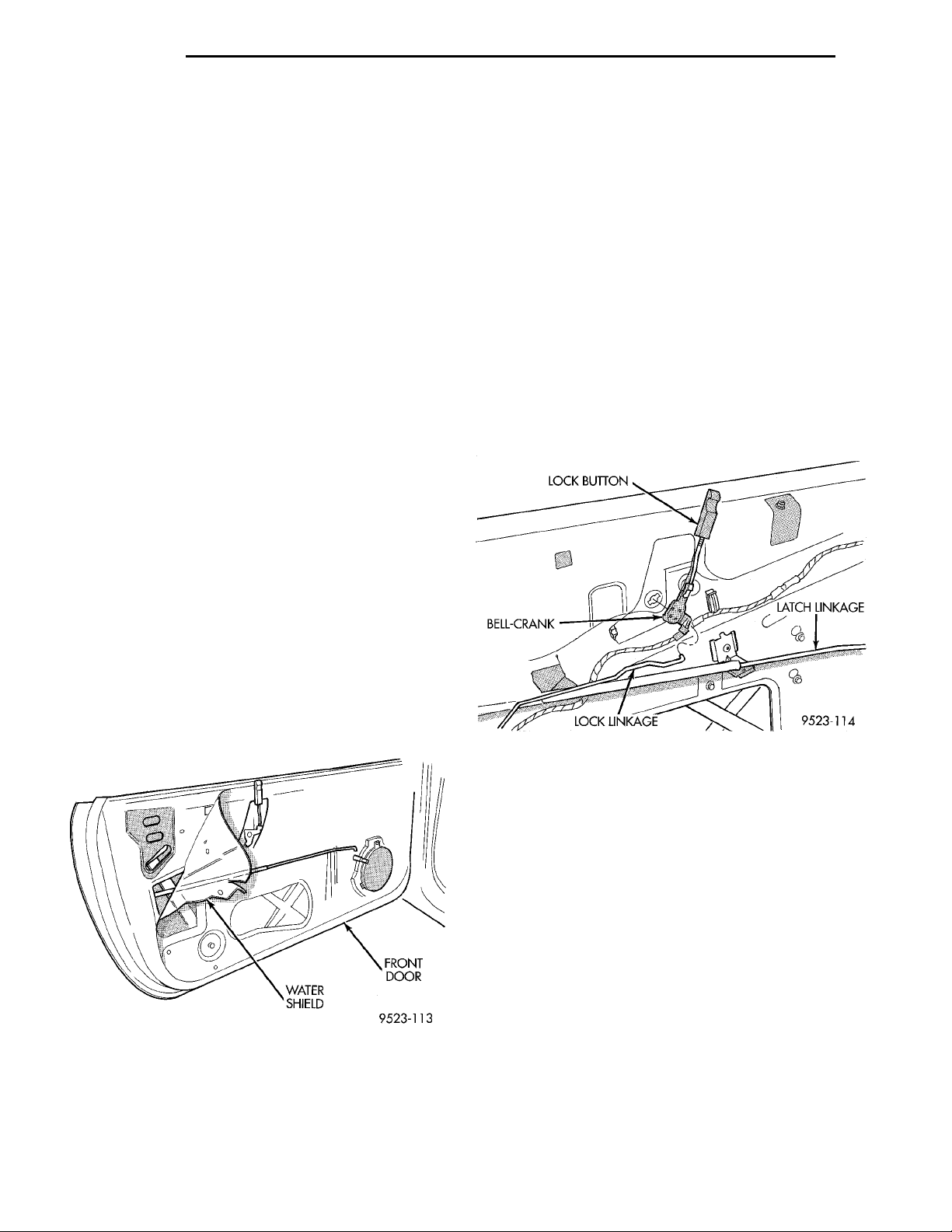
FRONT DOORWATER SHIELD
23 - 22 BODY PL
REMOVAL AND INSTALLATION (Continued)
INSTALLATION
(1) Replace any damaged or missing push–in fasteners from around perimeter of door trim panel.
(2) Place trim panel near door.
(3) Engage wire connector into power door lock
switch, mirror switch, and power window switch, if
so equipped.
(4) Insert latch rod into handle and engage clip.
(5) Engage trim panel into retainer channel at top
of door and push down to seat.
(6) Locate door trim panel to inner door panel by
aligning locating pins on backside of trim panel to
mating holes in inner door panel.
(7) Engage push-in fasteners to hold trim to door
panel around perimeter of trim panel.
(8) Install screw behind inside latch release handle.
(9) Install screw inside arm rest pull cup.
(10) With the window in the down position, orientate the window regulator crank handle appropriately. Install the right handle at the 10 o’clock
position and the left handle at the 2 o’clock position,
if so equipped.
FRONT DOOR WATER SHIELD
(2) Place the watershield into position and press
securely to adhesive making sure to properly route
wiring and linkages.
(3) Engage clip holding lock linkage to lock button
bell-crank.
(4) Install door trim pull cup mount bracket.
(5) Install door speaker, if equipped.
(6) Install door trim panel.
LOCK BUTTON BELL-CRANK
REMOVAL
(1) Remove door trim panel.
(2) Disengage clip holding lock linkage to bellcrank
(3) Rotate bell-crank until retaining ears align
with slots in door panel.
(4) Separate bell-crank from door (Fig. 11).
LOCK BUTTON LATCH LINKAGELOCK LINKAGEBELL-CRANK
REMOVAL
(1) Remove door trim panel.
(2) Remove Door speaker, if equipped.
(3) Remove door trim pull cup mount bracket.
(4) Disengage clip holding lock linkage to lock but-
ton bell crank.
(5) Peel water shield away from adhesive around
perimeter of inner door panel (Fig. 10).
Fig. 10 Water Shield
INSTALLATION
(1) Insure that enough adhesive remains to
securely retain the watershield. Replace as necessary.
Fig. 11 Lock Button Bell-crank
INSTALLATION
Reverse the preceding operation.
FRONT DOOR INNER BELT WEATHERSTRIP
REMOVAL
(1) Remove door trim panel.
(2) Separate weatherstrip from door.
INSTALLATION
(1) Push down on weatherstrip to engage channel
to door panel.
(2) Install door trim panel.
WINDOW INNERBELT STABILIZER
REMOVAL
(1) Remove door trim panel.
(2) Remove nut holding inner belt stabilizer to
door panel.
Page 23
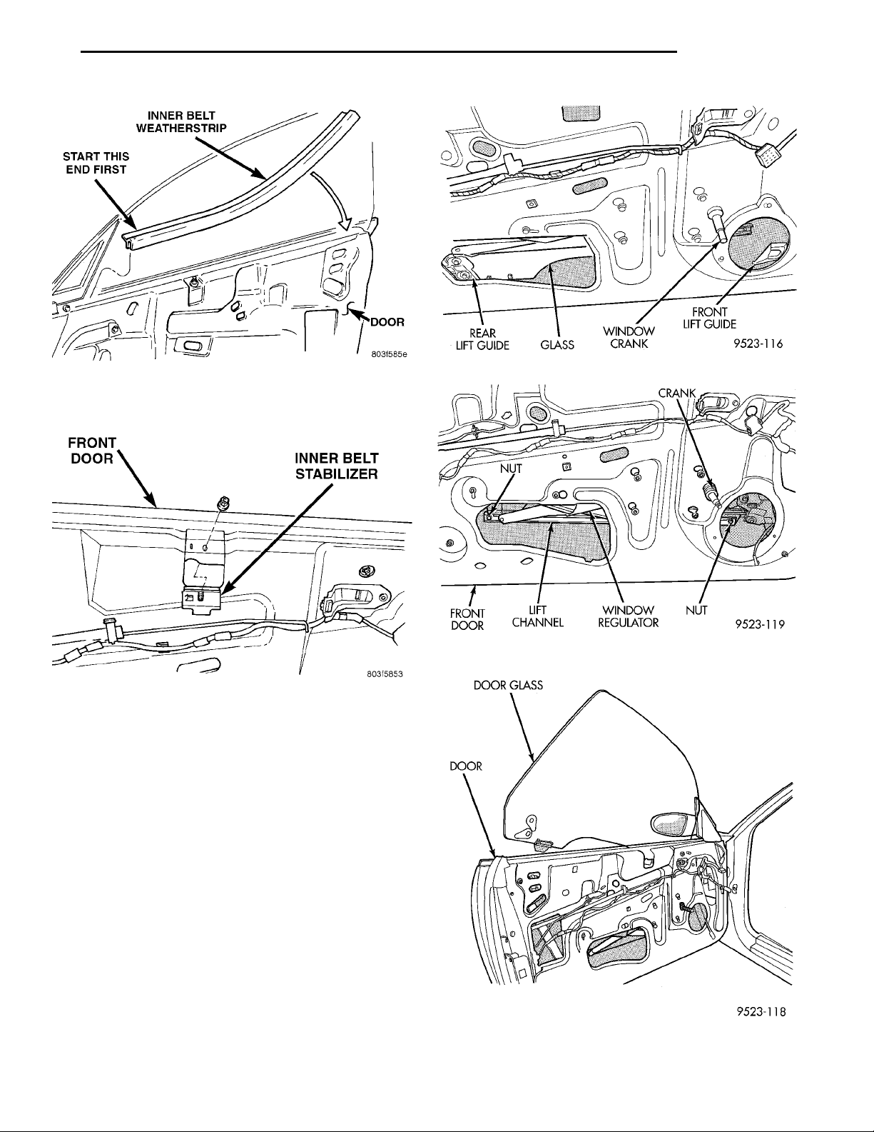
DOOR GLASSDOOR
START THIS ENDFIRSTINNER BELTWEATHERSTRIP DOOR
FRONT DOOR INNER BELT STABILIZER
PL BODY 23 - 23
REMOVAL AND INSTALLATION (Continued)
Fig. 12 Front Door Inner Belt Weatherstrip
(3) Separate inner belt stabilizer from door. (Fig.
13)
Fig. 13
INSTALLATION
Reverse the preceding operation. Adjust inner belt
stabilizer against glass with enough tension to allow
free up and down movement.
Fig. 14 Guide Bolts
Fig. 15 Regulator Lift Channel
FRONT DOOR GLASS—2 DOOR
REMOVAL
(1) Remove door trim panel and water shield.
(2) Remove inner and outer door belt weatherstrips.
(3) Loosen inner belt stabilizer.
(4) Lower door glass to bottom of travel to access
glass attachment bolts.
(5) Remove bolts holding regulator lift channel to
door glass (Fig. 15).
(6) Remove bolts holding rear guide plate to door
glass (Fig. 14).
(7) Separate rear guide plate from door glass.
(8) Lift door glass upward and out of opening at
top of door (Fig. 16).
(9) Remove front guide plate from door glass.
Fig. 16 Door Glass
Page 24
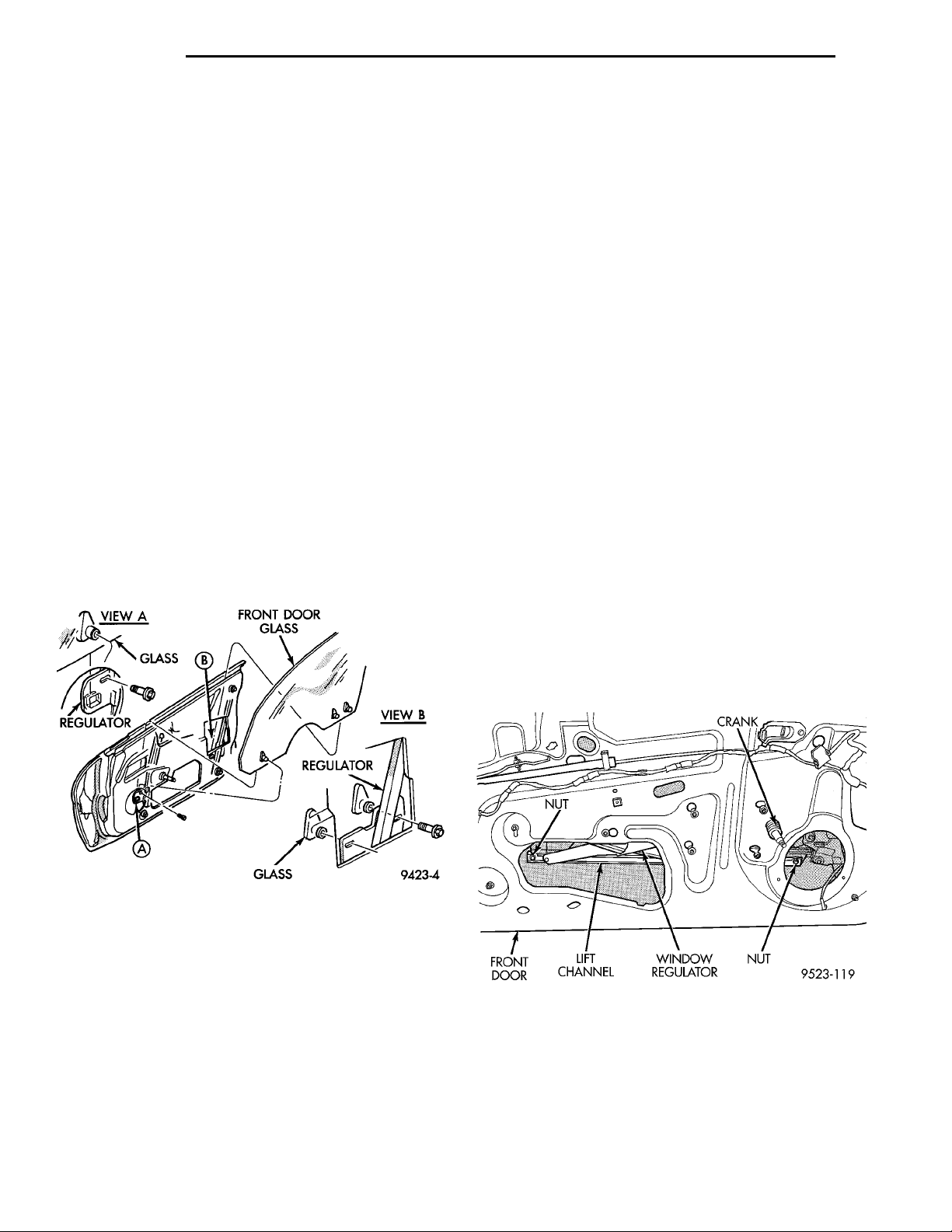
VIEW AGLASSREGULATOR FRONT DOOR GLASS VIEW BREGULATORGLASS
CRANKNUTWINDOW REGU-LATORLIFT CHANNELFRONT DOOR NUT
23 - 24 BODY PL
REMOVAL AND INSTALLATION (Continued)
INSTALLATION
(1) Install front guide plate to door glass.
(2) Carefully lower door glass through opening in
top of door.
(3) Position rear guide plate onto door glass and
install bolts.
(4) Install nuts holding regulator lift channel to
door glass.
(5) Tighten all door glass fasteners.
(6) Tighten window inner belt stabilizer.
(7) Install inner and outer door belt weatherstrips.
(8) Install door trim panel and water shield.
FRONT DOOR GLASS—4 DOOR
REMOVAL
(1) Remove door trim panel and water shield.
(2) Remove inner door belt weatherstrip.
(3) Loosen window inner belt stabilizer.
(4) Lower door glass to bottom of door to gain
access to attaching bolts.
(5) Remove bolts holding door glass to window regulator lift plates (Fig. 17).
(6) Disengage door glass from regulator.
(7) Lift door glass upward out of the opening at
the top of door.
WINDOW REGULATOR—2 DOOR
NOTE: Power and manual door glass regulators are
serviced using the same procedures. For power
window motor service procedures, refer to Group
8S, Power Windows.
REMOVAL
(1) Remove door trim panel and water shield.
(2) Disconnect wire connector to power window
motor, if so equipped.
(3) Remove nuts holding regulator lift channel to
door glass (Fig. 18).
(4) Secure door glass in upward position.
(5) Mark position of rear bolt of roller channel to
inner door panel to aid in installation.
(6) Remove bolt holding rear of roller channel to
door panel.
(7) Loosen bolt holding front of roller channel to
door panel.
(8) Separate roller channel from door panel (Fig.
19).
(9) Loosen bolts holding window regulator to inner
door panel.
(10) Separate bolt heads from key-hole slots in
inner door panel.
(11) Remove window regulator through large hole
in inner door panel (Fig. 20) and (Fig. 21).
(12) Remove power window motor from regulator,
if so equipped. Refer to Group 8S for Power Window
Motor procedure.
Fig. 17 Front Door Glass
INSTALLATION
(1) Carefully lower door glass through opening in
top of door.
(2) Position door glass into window regulator lift
plates.
(3) Install bolts securing door glass to lift plates.
(4) Tighten window inner belt stabilizer.
(5) Install inner door belt weatherstrip.
(6) Install door trim panel and water shield.
Fig. 18 Regulator Lift Channel
Page 25
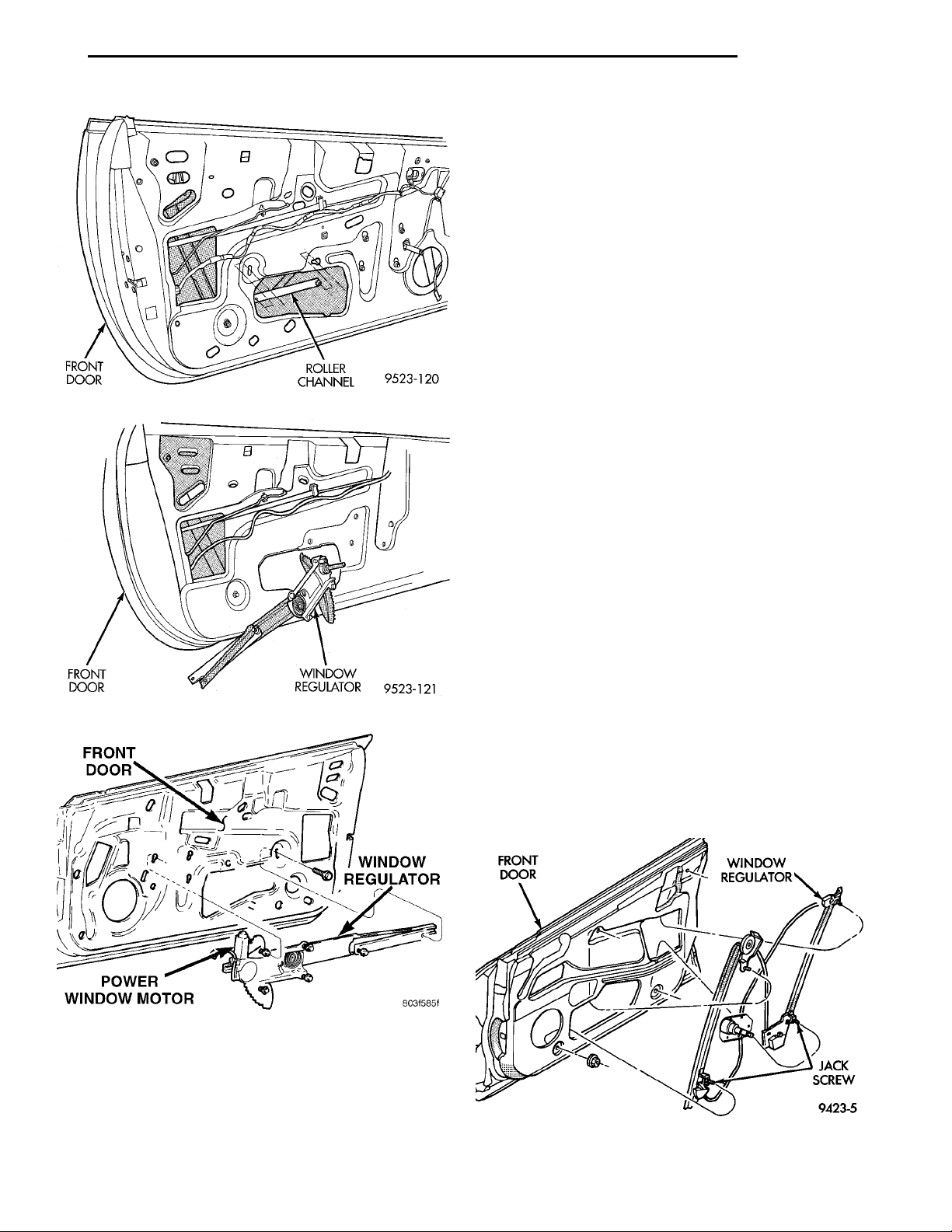
ROLLER CHANNELFRONT DOOR
FRONT DOOR WINDOW REGULA-TORPOWER WINDOW MOTOR
WINDOW REGULATORFRONT DOOR
PL BODY 23 - 25
REMOVAL AND INSTALLATION (Continued)
(2) Move window regulator into position in door
and engage bolt heads into key-hole slots in inner
door panel and tighten bolts.
(3) Install roller channel to door panel.
(4) Install bolt at rear of roller channel. Make sure
that bolt is aligned to mark on inner door panel
made previously.
(5) Tighten front and rear bolts of roller channel.
(6) Install nuts holding regulator lift channel to
door glass.
(7) Adjust door glass as described in this section.
(8) Connect wire connector to power window motor,
if so equipped.
(9) Install door speaker, if so equipped.
(10) Install door trim panel and water shield.
Fig. 19 Roller Channel
WINDOW REGULATOR—4 DOOR
NOTE: Power and manual door glass regulators are
serviced using the same procedures. For power
window motor service procedures, refer to Group
8S, Power Windows.
Fig. 20 Manual Window Regulator
REMOVAL
(1) Remove door trim panel and water shield.
(2) Remove door glass.
(3) Disconnect wire connector to power window
motor, if so equipped.
(4) Remove nuts holding top of regulator to inner
door panel.
(5) Remove nuts holding bottom of regulator to
door panel (Fig. 22) and (Fig. 23).
(6) Loosen bolts holding regulator crank/motor to
door panel.
(7) Disengage bolts from key hole slots in door panel.
FRONT DOOR WINDOW REGULATORJACK SCREW
(8) Remove window regulator from access hole in
door panel.
(9) Remove power window motor from regulator, if
so equipped. Refer to Group 8S for Power Window
Motor procedures.
Fig. 21 Power Window Regulator
INSTALLATION
(1) Install power window motor on regulator, if so
equipped. Refer to group 8S for Power Window Motor
procedures.
Fig. 22 Front Door Manual Window Regulator
Page 26
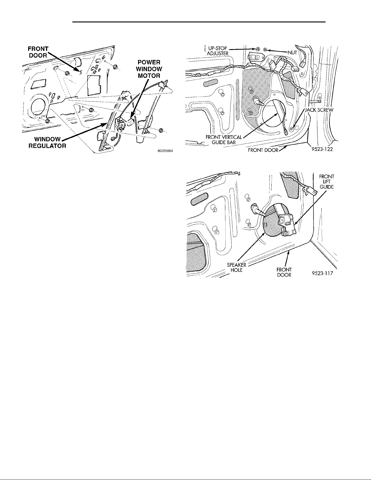
FRONT DOOR POWER WINDOW MOTORWINDOW REGULATOR
UP-STOP
ADJUSTER
NUT JACK SCREWFRONT DOORFRONT VERTICALGUIDE BAR
FRONT LIFTGUIDEFRONT DOORSPEAKER HOLE
23 - 26 BODY PL
REMOVAL AND INSTALLATION (Continued)
Fig. 23 Front Door Power Window Regulator
INSTALLATION
(1) Install power window motor on regulator, if so
equipped. Refer to Group 8S for Power Window
Motor procedures.
(2) Move window regulator into position in door
and engage bolt heads in key-slots in inner door
panel.
(3) Tighten bolts attaching regulator crank/motor
to door panel.
(4) Install nuts holding top and bottom of window
regulator to door panel.
(5) Install door glass. Refer to procedures in this
section to verify and adjust glass alignment.
(6) Connect wire connector to power window motor,
if so equipped.
(7) Install door speaker, if so equipped.
(8) Install door trim panel and water shield.
FRONT VERTICAL GUIDE BAR
REMOVAL
(1) Remove door trim panel and water shield.
(2) Remove door speaker, if equipped.
(3) Remove front lift guide.
(4) Remove bolt holding top of front guide bar to
inner door panel.
(5) Using a Snap-ont flare-nut socket (FRXM10)
and a hex wrench, remove nut holding bottom of
guide bar to door panel while holding jack screws.
(Fig. 24)
(6) Remove front vertical guide bar through
speaker hole in inner door panel (Fig. 25).
Fig. 24 Front Vertical Guide Bar
Fig. 25 Front Guide
REAR VERTICAL GUIDE BAR
REMOVAL
(1) Remove door trim panel and water shield.
(2) Remove nut holding top of rear guide bar to
inner door panel.
(3) Using a Snap-ont flare-nut socket (FRXM10)
and a hex wrench, remove nut holding bottom of
guide bar to door panel while holding jack screws.
(4) Remove rear vertical guide bar through large
access hole in inner door panel (Fig. 26).
INSTALLATION
Reverse the preceding operations and verify glass
alignment.
INSTALLATION
Reverse the preceding operation. Verify door glass
alignment, adjust if necessary.
FRONT DOOR LATCH
REMOVAL
(1) Remove door trim panel and water shield.
(2) Close door glass.
Page 27
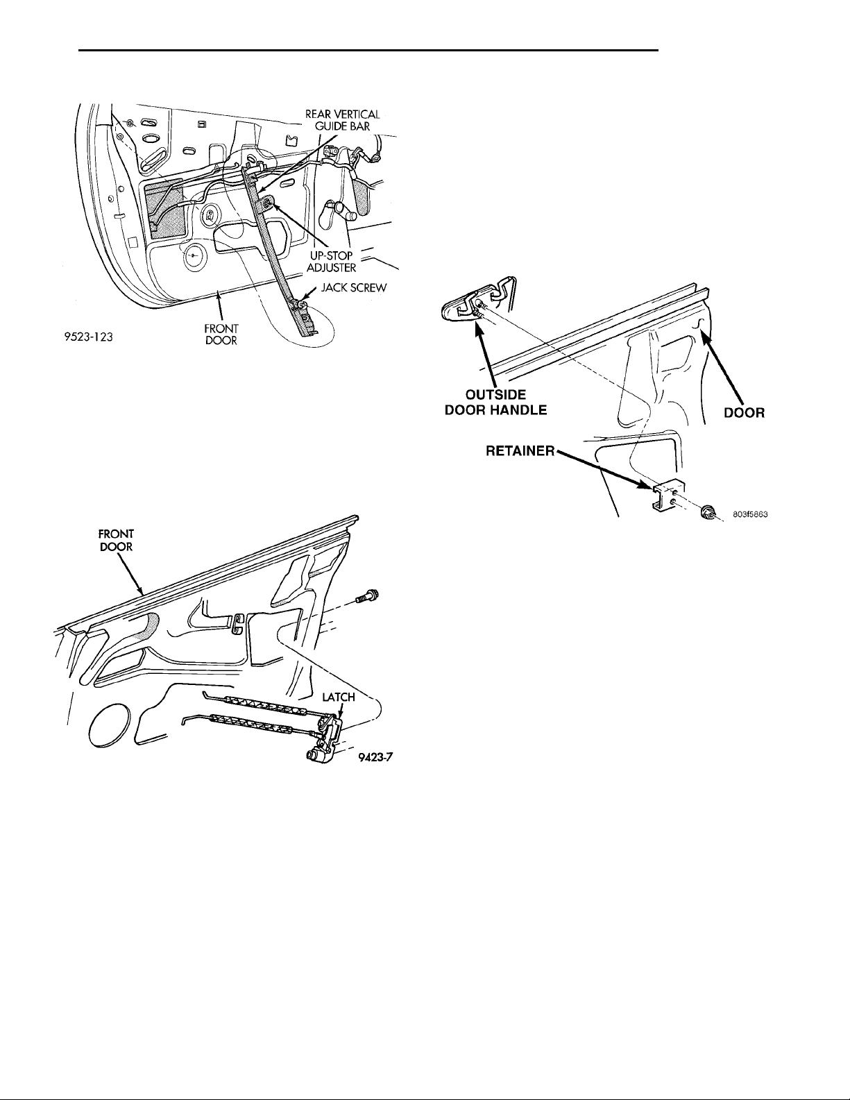
REAR VERTICALGUIDE BARUP-STOPADJUSTERJACK SCREWFRONT DOOR
PL BODY 23 - 27
REMOVAL AND INSTALLATION (Continued)
FRONT DOOR OUTSIDE HANDLE
REMOVAL
(1) Remove door trim panel and water shield.
(2) Close door glass.
(3) Disconnect lock and latch rods from door latch.
(4) Remove nut holding door handle retainer to
outer door panel (Fig. 28).
(5) Separate retainer from back of door handle.
(6) Separate door handle from vehicle.
Fig. 26 Rear Vertical Guide Bar
(3) Disconnect lock and latch rods from door latch
(Fig. 27).
(4) Disengage wire connector from power door lock
motor, if equipped.
(5) Remove screws holding latch to door end
frame.
(6) Separate door latch from vehicle.
Fig. 27 Front Door Latch
INSTALLATION
CAUTION: Do not close door before adjusting the
door latch. Door may fail to re-open.
(1) Position door latch inside door and install
screws holding latch to door end frame.
(2) Engage wire connector into power door lock
motor, if so equipped.
(3) Connect latch and lock rods to door latch.
(4) Install door trim panel and water shield.
(5) Adjust door latch using procedure in this sec-
tion.
Fig. 28 Front Door Outside Handle
INSTALLATION
(1) Position door handle into door and install
retainer at back of handle.
(2) Install nut holding door handle retainer to
outer door panel.
(3) Connect lock and latch rods to door latch.
(4) Install door trim panel and water shield.
DOOR LOCK CYLINDER
REMOVAL
(1) Remove door trim panel and water shield.
(2) Close door glass.
(3) Disconnect door lock rod from latch.
(4) Remove clip holding lock cylinder to door handle.
(5) Pull lock cylinder from door handle (Fig. 29).
INSTALLATION
(1) Push lock cylinder into door handle.
(2) Install clip holding lock cylinder to door handle.
(3) Connect door lock rod from latch.
(4) Install door trim panel and water shield.
Page 28
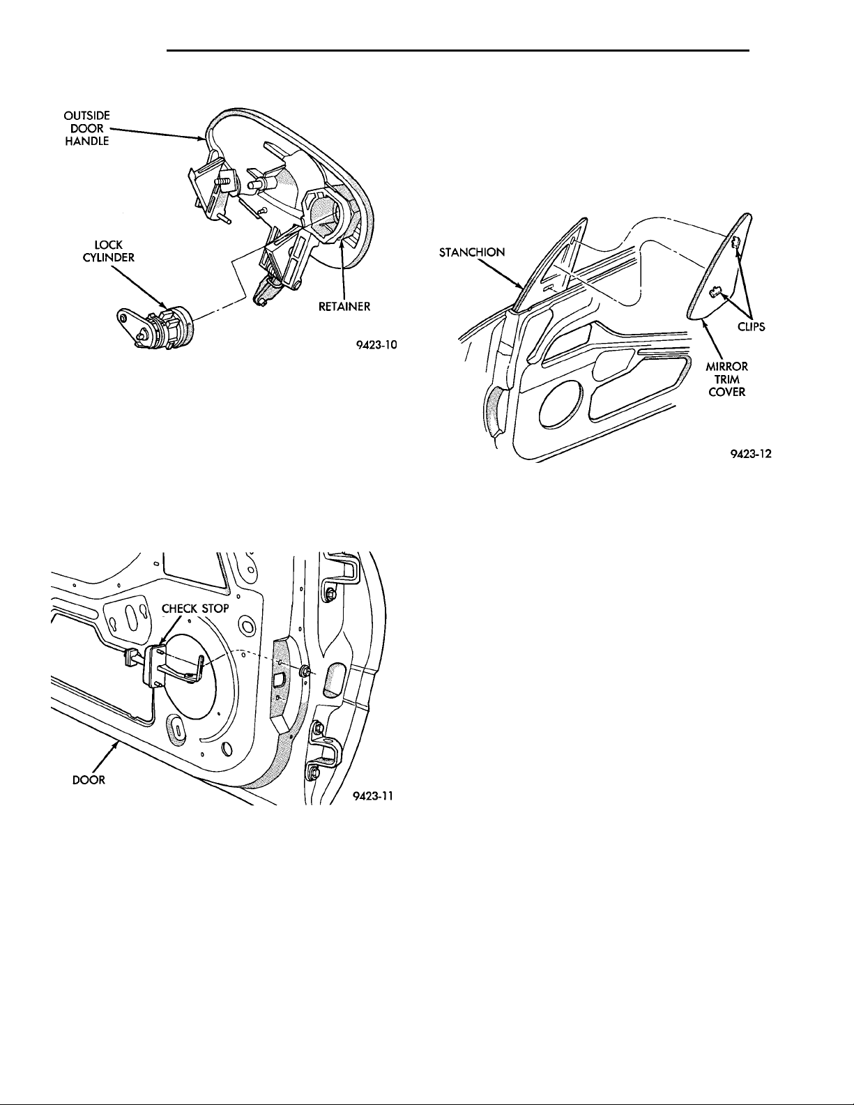
OUTSIDEDOOR HAN-DLELOCK CYLINDER RETAINER
CHECK STOPDOOR
STANCHION CLIPSMIRROR TRIMCOVER
23 - 28 BODY PL
REMOVAL AND INSTALLATION (Continued)
SIDE VIEW MIRROR TRIM COVER
REMOVAL
(1) Disengage clips holding side view mirror cover
to stanchion (Fig. 31).
(2) Separate mirror cover from vehicle.
Fig. 29 Door Lock Cylinder
FRONT DOOR CHECK STOP
REMOVAL
(1) Remove door trim panel and water shield.
(2) Remove bolt holding check stop to hinge pillar.
(3) Remove door speaker.
(4) Remove bolts holding check stop to door end
frame (Fig. 30).
(5) Separate check stop from vehicle.
Fig. 30 Front Door Check Stop
INSTALLATION
(1) Position door check on vehicle and install bolts
attaching stop to door end frame.
(2) Install door speaker, if so equipped.
(3) Install bolt holding door check stop to hinge
pillar.
(4) Install door trim panel and water shield.
Fig. 31 Side View Mirror Trim Cover
INSTALLATION
Reverse the preceding operation.
SIDE VIEW MIRROR
REMOVAL
(1) Remove side view mirror cover.
(2) Remove door trim panel.
(3) Remove water shield if equipped with power
mirror.
(4) Disengage wire connector from power mirror
motor, if equipped.
(5) Remove bolts holding mirror to stanchion (Fig.
32).
(6) Separate mirror from vehicle.
INSTALLATION
(1) Position side view mirror on vehicle and install
nuts attaching mirror to stanchion.
(2) Engage wire connector from power window
motor, if so equipped.
(3) Install water shield if equipped with power
mirror.
(4) Install door trim panel.
(5) Install side view mirror trim cover.
Page 29
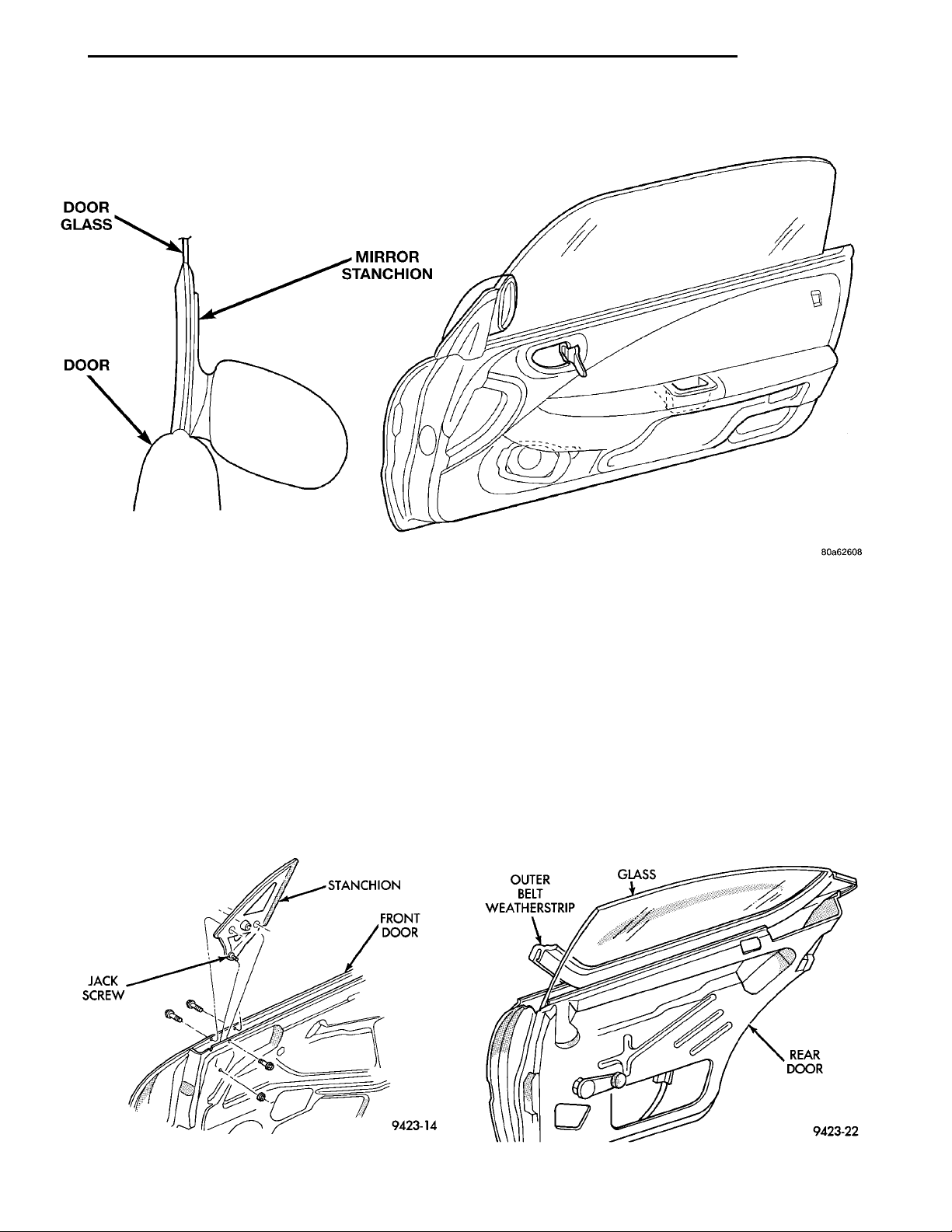
JACK SCREW STANCHIONFRONT DOOR
DOOR GLASSMIRROR STANCHIONDOOR
OUTER BELTWEATHERSTRIP GLASS REAR DOOR
PL BODY 23 - 29
REMOVAL AND INSTALLATION (Continued)
Fig. 32 Side View Mirror
SIDE VIEW MIRROR STANCHION
REMOVAL
(1) Remove side view mirror.
(2) Remove bolt holding top of side view mirror
stanchion to inner door panel.
(3) Remove bolts holding stanchion to outer door
panel (Fig. 33).
(4) Remove nut holding stanchion jack-screw to
inner door panel.
(5) Disengage push-in fastener holding door open-
ing weatherstrip to stanchion.
(6) Separate stanchion from vehicle.
INSTALLATION
Reverse the preceding operation. Using a Snap-on
flare-nut socket (FRXM10) and hex-wrench adjust
the jack-screw at bottom of stanchion to achieve
proper alignment.
FRONT DOOR OUTER BELT WEATHERSTRIP
REMOVAL
(1) Open door glass.
(2) Pull upward at rear end of outer belt weatherstrip.
(3) Separate outer belt weatherstrip from vehicle
(Fig. 34).
Fig. 33 Side View Mirror Stanchion
Fig. 34 Outer Belt Weatherstrip—Typical
Page 30
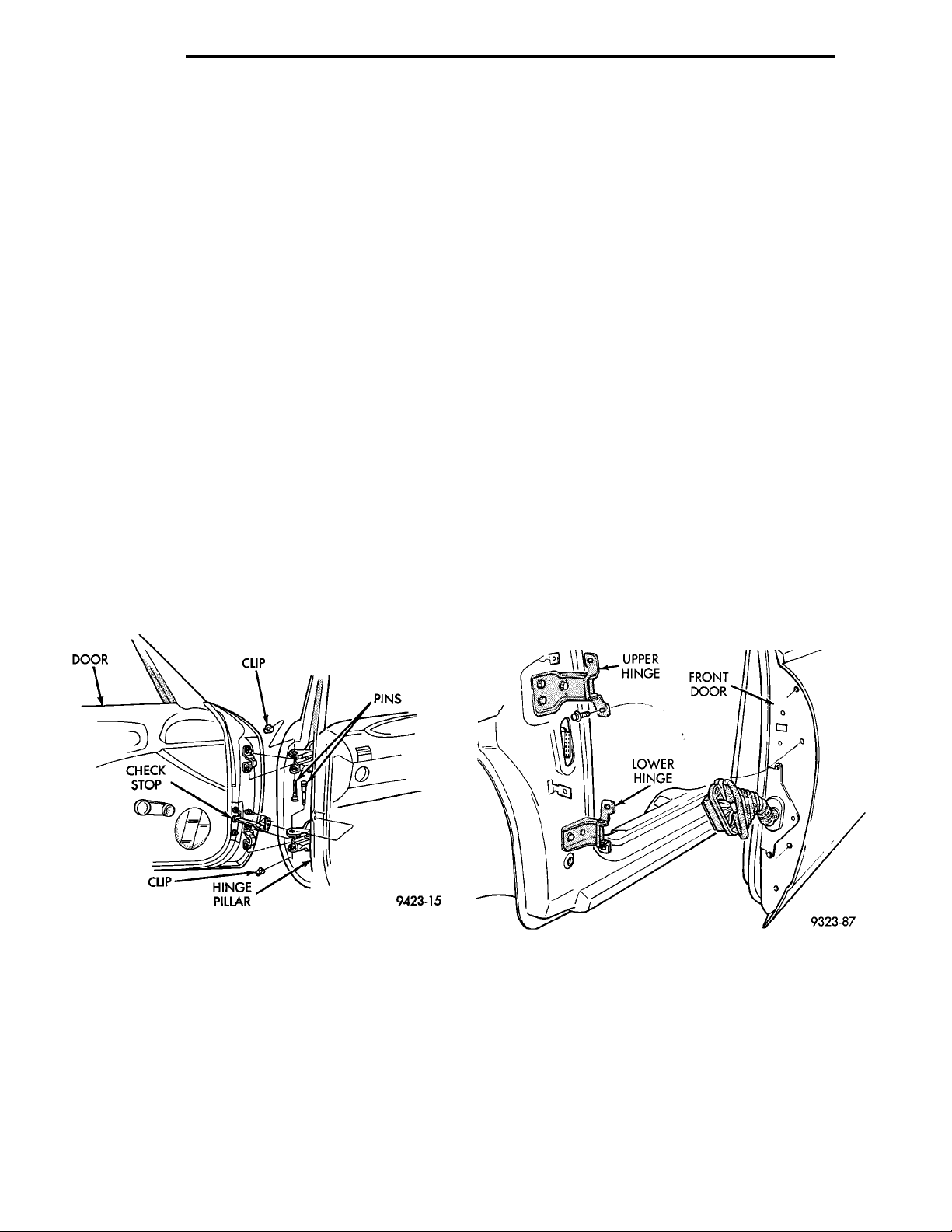
23 - 30 BODY PL
REMOVAL AND INSTALLATION (Continued)
INSTALLATION
(1) Starting at leading edge of door, press weather-
strip onto door.
(2) Operate window and check for interference
DOOR
The procedure for servicing the front and rear
doors are the same. Refer to the following procedure
when servicing either door.
REMOVAL
NOTE: The retaining clips used on the door hinge
pins are not to be re-used. Verify availability prior to
proceeding.
(1) Open and support door on a suitable lifting
device.
(2) Disengage wire connector at hinge pillar, if necessary.
(3) Remove bolts holding door check strap to hinge
pillar.
(4) Remove clip holding hinge pin in lower door
hinge.
(5) Remove pin from lower hinge (Fig. 35).
(6) Remove clip holding hinge pin in upper hinge.
(7) Remove pin from upper hinge (Fig. 35).
(8) Separate door from vehicle.
(4) Install new clip holding hinge pin in upper
hinge.
(5) Install new clip holding pin in lower hinge.
(6) Install bolts holding door check strap to hinge
pillar.
(7) Engage wire connector at hinge pillar, if neces-
sary.
DOOR HINGE
The procedure for replacing the front and rear door
hinges are the same. Refer to the following procedure
when servicing either hinge.
NOTE: If both hinges on one door are to be
replaced, remove and install one hinge completely
prior to beginning the second hinge.
REMOVAL
(1) Open and support door on a suitable lifting
device.
(2) Remove bolts holding door check strap to lower
A–pillar for greater access, if necessary.
(3) Mark position of hinge on both the door end
frame and lower A–pillar to ease installation.
(4) Remove bolts holding hinge to door end frame
(Fig. 36).
(5) Remove bolts holding hinge to lower A–pillar.
(6) Separate door hinge from vehicle.
Fig. 35 Door
INSTALLATION
(1) Apply Mopart Multimileage Grease to inside of
door hinge bushings.
(2) Position door on vehicle and install pin in
upper hinge. Align knurling on hinge pin with the
grooves in the door hinge prior to driving in the
hinge pin.
(3) Install pin in lower hinge.
NOTE: Verify that head of each hinge pin is fully
seated into door hinge.
Fig. 36 Door and Hinge—Typical
INSTALLATION
CAUTION: When installing a new hinge, make sure
that the head of each hinge pin is fully seated into
the door hinge. Also, remove the plastic shipping
clip and replace it with the correct metal retaining
clip once the hinge pin is seated.
(1) If necessary, paint new door hinge prior to
installation.
Page 31
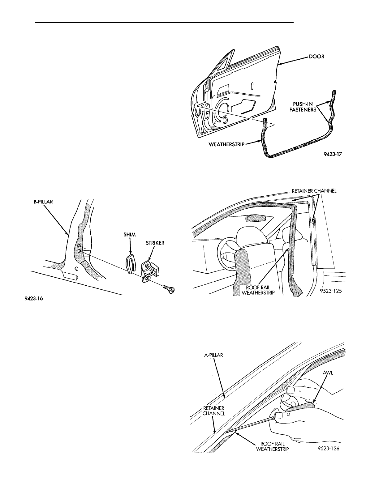
B-PILLAR SHIM STRIKER
DOORPUSH-IN FASTEN-ERSWEATHERSTRIP
PL BODY 23 - 31
REMOVAL AND INSTALLATION (Continued)
(2) Position door hinge on vehicle.
(3) Loosely install bolts holding hinge to lower
A–pillar.
(4) Loosely install bolts holding hinge to door end
frame.
(5) Align hinge to marks made previously and
tighten all bolts.
(6) Install bolts holding door check strap to lower
A–pillar, if removed previously.
(7) Verify door fit and operation. Adjust door hinge
for proper door alignment, if necessary.
FRONT DOOR LATCH STRIKER
REMOVAL
(1) Mark outline of door latch striker on B-pillar to
aid installation.
(2) Remove screws holding door latch striker to
B-pillar (Fig. 37).
(3) Separate door latch striker from vehicle.
(3) Pull roof rail weatherstrip from retainer chan-
nel.
Fig. 38 Front Door Weatherstrip
Fig. 37 Front Door Latch Striker
INSTALLATION
Reverse the preceding operation.
FRONT DOOR WEATHERSTRIP
REMOVAL
(1) Using a fork-type prying tool, disengage push-in
fasteners holding weatherstrip to door (Fig. 38).
(2) Separate weatherstrip from door.
INSTALLATION
Reverse the preceding operation.
ROOF RAIL WEATHERSTRIP
REMOVAL
(1) Using a fork tool C-4829, Disengage push-in
fasteners holding bottom of weatherstrip to B-pillar.
(2) Disengage push-in fasteners holding bottom of
weatherstrip to A-pillar (Fig. 39).
Fig. 39 Roof Rail Weatherstrip
A-PILLAR AWLROOF RAIL WEATHERSTRIPRETAINERCHANNEL
INSTALLATION
Reverse the preceding operation. Zip roof rail
weatherstrip into retainer channel using a suitable
awl (Fig. 40).
Fig. 40 Install Roof Rail Weatherstrip
Page 32
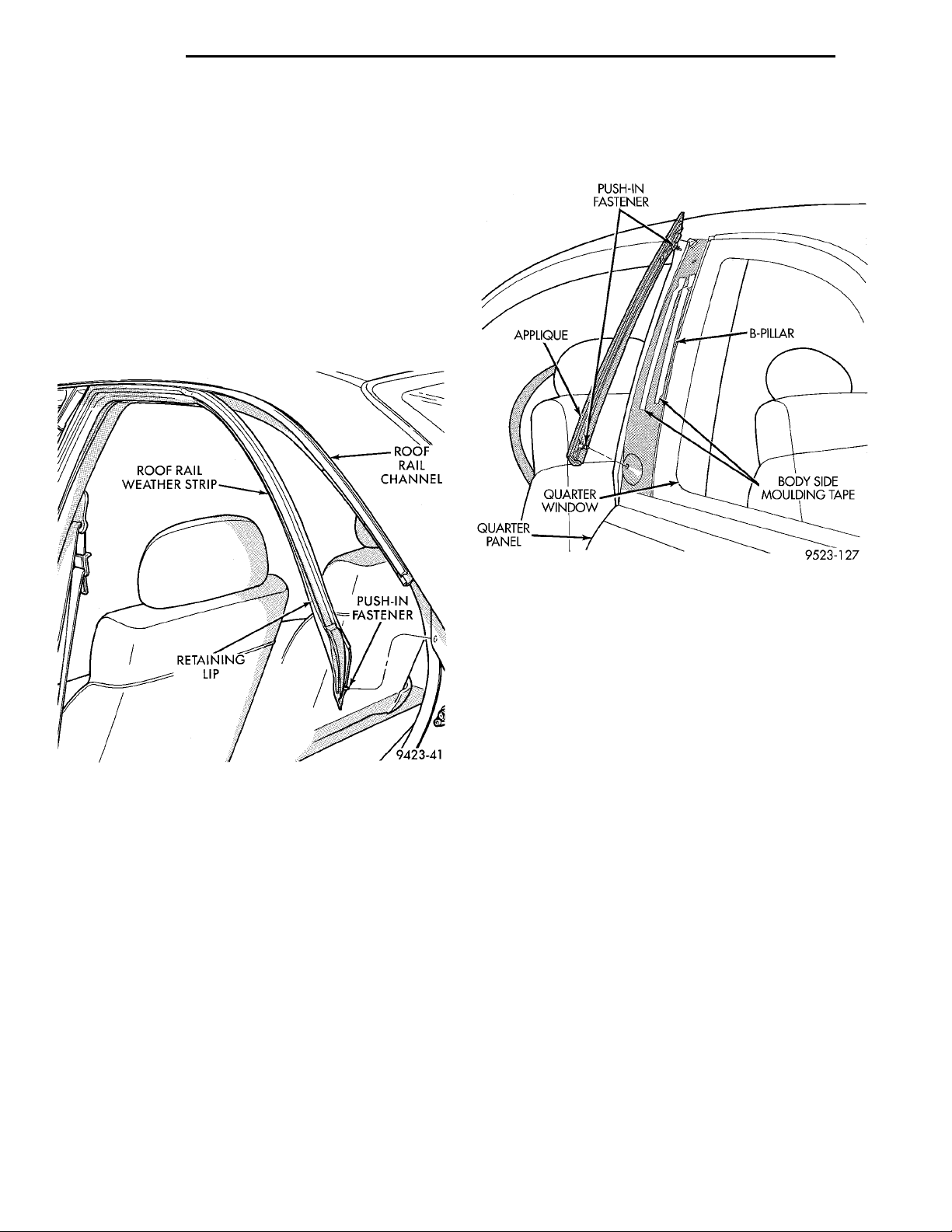
23 - 32 BODY PL
REMOVAL AND INSTALLATION (Continued)
ROOF RAIL WEATHERSTRIP
REMOVAL
(1) Remove B-pillar applique.
(2) Remove push-in fasteners holding bottom of
roof rail weatherstrip to B-pillar.
(3) Remove push-in fastener holding rearward end
of weatherstrip to quarter panel.
(4) Remove push-in fasteners holding weatherstrip
to front door hinge pillar.
(5) Pull weatherstrip from retainer channel under
drip rail (Fig. 41).
(6) Pull weatherstrip from B-pillar channels.
(7) Separate roof rail weatherstrip from vehicle.
(4) Disengage push-in fastener holding top of
applique to B- pillar.
(5) Separate applique from vehicle.
Fig. 41 Roof Rail Weatherstrip
INSTALLATION
(1) Place weatherstrip in position on B-pillar
retainer channels.
(2) Insert weatherstrip into channels.
(3) Using a suitable awl, zip retaining lip on back
of weatherstrip into B-pillar and roof rail channels.
(4) Install push-in fasteners to hold weatherstrip
to B-pillar, hinge pillar and quarter panel.
B-PILLAR APPLIQUE—2 DOOR
REMOVAL
(1) Using a trim stick C-4755, pry bottom of appli-
que away from B-pillar.
(2) Disengage push-in fastener holding bottom of
applique to B-pillar.
(3) Separate applique from body side molding tape
on back of applique (Fig. 42).
Fig. 42 B-pillar Applique
INSTALLATION
Reverse the preceding operation. Carefully remove
adhesive residue from back of applique and B-pillar.
Install new body side molding adhesive tape on back
of applique.
B-PILLAR APPLIQUE—4 DOOR
REMOVAL
(1) Open doors to gain access to bottom of B-pillar
applique.
(2) Disengage push-in fastener holding bottom of
applique to B-pillar.
(3) If temperature in work area is below 21°C
(70°F), heat applique to aid adhesive separation from
fastening tape.
(4) Pull outward at bottom of applique to separate
tape from B-pillar.
(5) Disengage push-in fastener holding top of
applique to B-pillar.
(6) Separate applique from vehicle (Fig. 43).
INSTALLATION
Reverse the preceding operation. Carefully remove
adhesive residue from applique and car body. Apply
new body side molding adhesive tape on back side of
applique.
Page 33
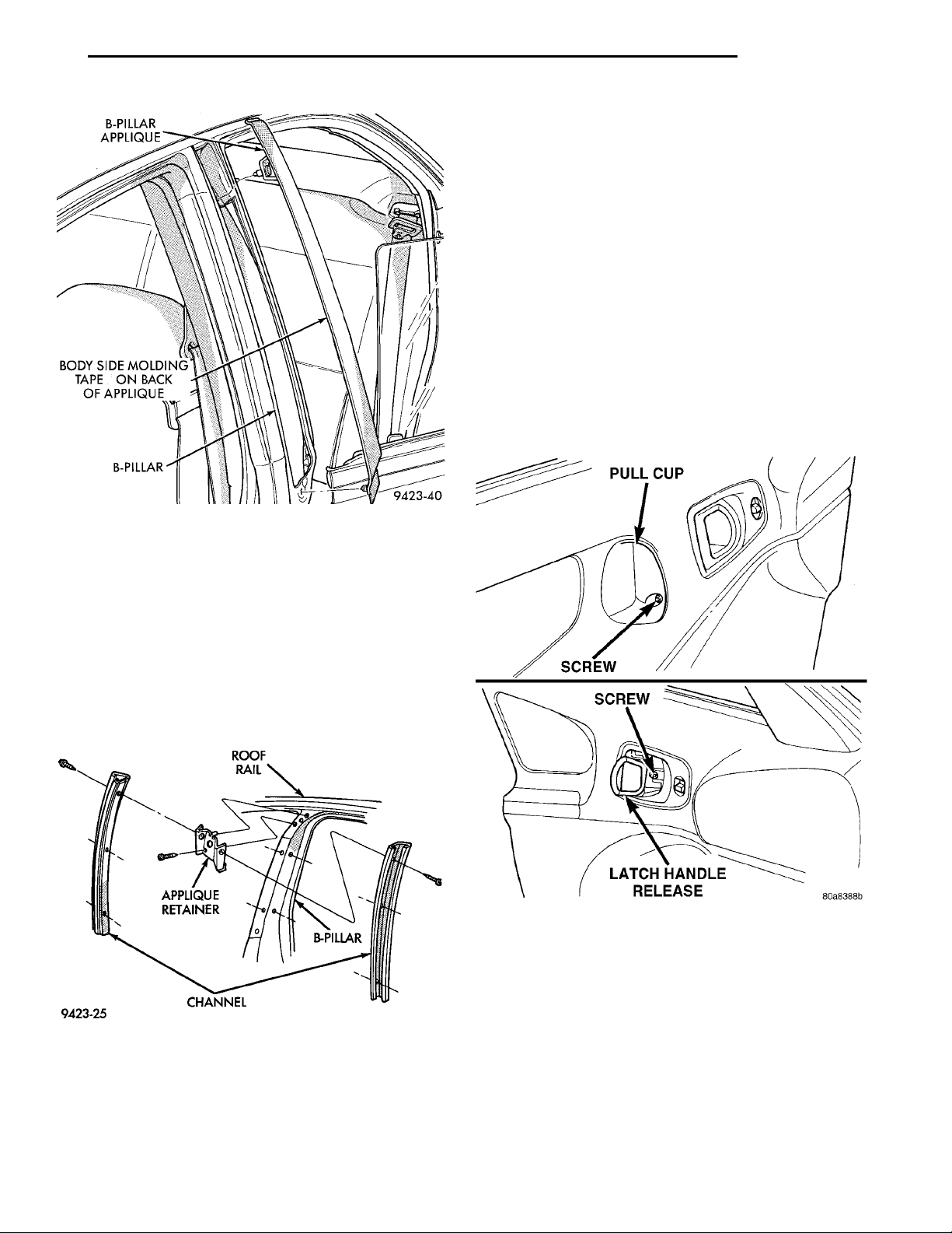
B-PILLAR APPLIQUEBODY SIDE MOLDING TAPEON BACK OF APPLIQUEB-PILLAR
ROOF RAIL B-PILLARCHANNELAPPLIQUE RETAINER
PULL CUPSCREWSCREWLATCH HANDLE RELEASE
PL BODY 23 - 33
REMOVAL AND INSTALLATION (Continued)
REAR DOOR TRIM
REMOVAL
(1) Release door latch and open door.
(2) Lower window glass.
(3) Remove window regulator crank.
(4) Remove screw from inside arm rest pull cup.
(5) Remove screw from behind inside latch release
handle (Fig. 45).
(6) Disengage push-in fasteners holding trim to
door panel around perimeter of trim panel.
(7) Disengage trim panel from retainer channel in
inner belt weatherstrip at top of door by lifting while
jiggling.
(8) Tilt top of trim panel away from door and disengage clip holding latch rod to handle.
(9) Separate latch rod from handle.
(10) Separate trim panel from door.
Fig. 43 B-pillar Applique
B-PILLAR WEATHERSTRIP CHANNEL
REMOVAL
(1) Remove B-pillar applique.
(2) Remove push-in fasteners holding weatherstrip
to B-pillar.
(3) Pull weatherstrip from B-pillar channels.
(4) Remove screws holding channels to B-pillar
(Fig. 44).
(5) Separate channels from B-pillar.
Fig. 44 B-pillar Weatherstrip Channel
INSTALLATION
Reverse the preceding operation.
Fig. 45 Rear Door Trim
INSTALLATION
(1) Replace any damaged or missing push–in fasteners from around perimeter of door trim panel.
(2) Place trim panel in position on door.
(3) Insert latch rod into handle and engage clip.
(4) Engage trim panel into retainer channel at top
of door.
(5) Locate door trim panel to inner door panel by
aligning locating pins on backside of trim panel to
mating holes in inner door panel.
(6) Engage push-in fasteners to hold trim to door
panel around perimeter of trim panel.
Page 34
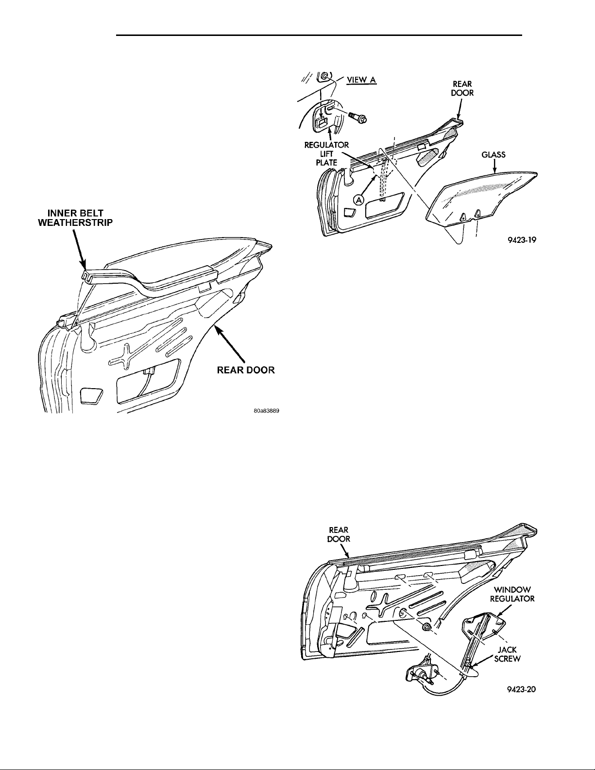
INNER BELT WEATHER-STRIPREAR DOOR
REGULATOR LIFT PLATE
VIEW A REAR DOOR GLASS
23 - 34 BODY PL
REMOVAL AND INSTALLATION (Continued)
(7) Install screw behind inside latch release han-
dle.
(8) Install screw inside arm rest pull cup.
(9) Install window regulator crank.
REAR DOOR INNER BELT WEATHERSTRIP
REMOVAL
(1) Remove door trim panel.
(2) Pull weatherstrip from top of door panel (Fig.
46).
(3) Separate weatherstrip from door.
Fig. 47 Rear Door Glass
(3) Raise glass and tighten window inner belt sta-
bilizer.
(4) Install inner door belt weatherstrip, water-
shield, and door trim panel.
(5) Operate window and check for interference.
Adjust glass as necessary.
Fig. 46 Rear Door Inner Belt Weatherstrip
INSTALLATION
(1) Place inner belt weatherstrip in position on
door.
(2) Push down on weatherstrip to engage channel
to door panel.
(3) Install door trim panel.
REAR DOOR GLASS
REMOVAL
(1) Remove door trim panel and water shield.
(2) Remove inner door belt weatherstrip.
(3) Loosen door glass jounce bumper.
(4) Lower door glass to bottom of door.
(5) Remove nuts holding door glass to window reg-
ulator lift plate (Fig. 47).
(6) Disengage door glass from regulator.
(7) Lift door glass upward out of the opening at
the top of door.
INSTALLATION
(1) Lower door glass through opening in top of
door and into position in the window regulator.
(2) Install nuts holding door glass to window reg-
ulator lift plate.
REAR DOOR WINDOW REGULATOR
REMOVAL
(1) Remove door trim panel and watershield.
(2) Remove door glass.
(3) Loosen bolts holding window regulator crank/
motor to door panel.
(4) Disengage bolt heads from keyhole slots in door
panel.
(5) Loosen bolts holding window regulator lift bar
to door panel.
(6) Disengage bolt heads from keyhole slots in door
panel (Fig. 48).
(7) Remove window regulator from door through
access hole in inner panel.
REAR DOOR WINDOW REGULA-TORJACK SCREW
Fig. 48 Rear Door Window Regulator
Page 35
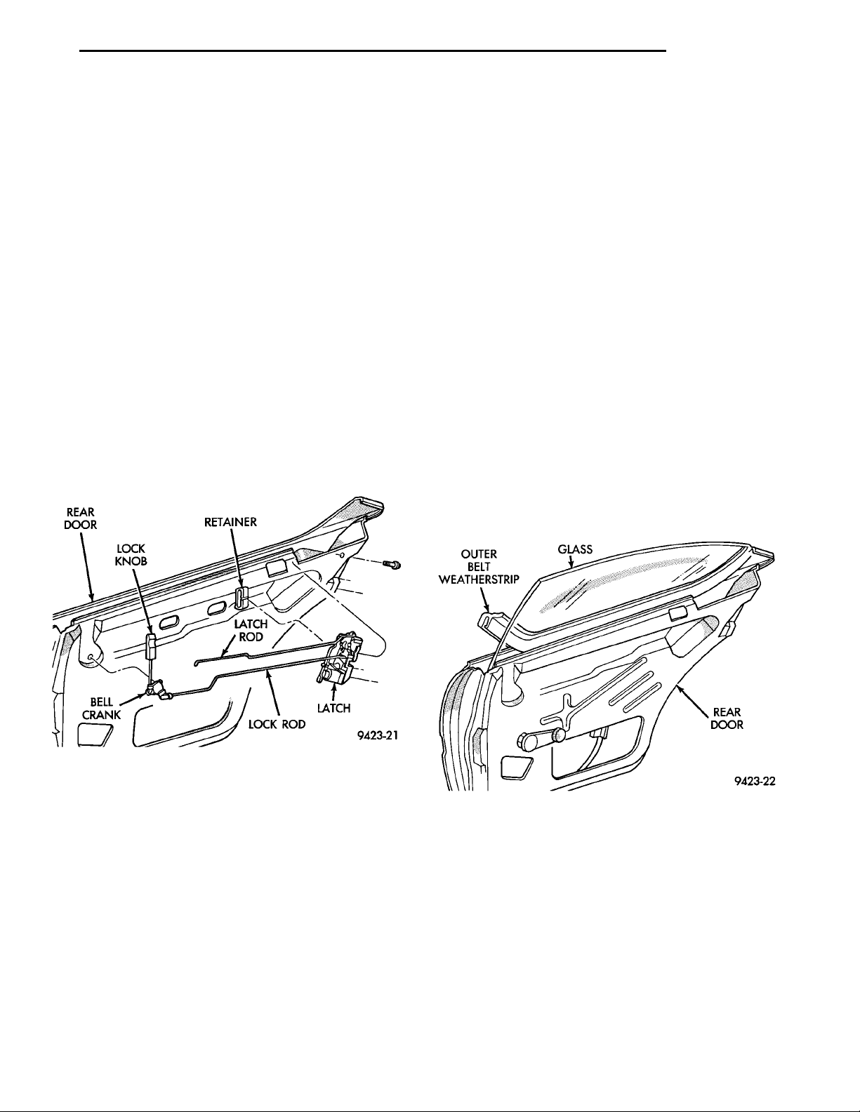
REAR DOORLOCK KNOB RETAINERLATCH ROD LATCHLOCK RODBELLCRANK
PL BODY 23 - 35
REMOVAL AND INSTALLATION (Continued)
INSTALLATION
(1) Move window regulator into position and
engage bolt heads into key-hole slots in inner door
panel.
(2) Tighten bolts holding window regulator lift bar
to inner door panel.
(3) Engage window regulator crank/motor bolts
into key-hole slots in door panel.
(4) Tighten window regulator crank/motor bolts.
(5) Install door glass, watershield, and door trim
panel.
REAR DOOR LATCH
REMOVAL
(1) Remove door trim panel and water shield.
(2) Close door glass.
(3) Disconnect lock and latch rods from door latch.
(4) Disengage wire connector from power door lock
motor, if equipped.
(5) Remove screws holding latch to door end frame
(Fig. 49).
(6) Separate door latch from vehicle.
OUTER BELTWEATHERSTRIP GLASS REAR DOOR
(2) Engage wire connector to power door lock
motor, if so equipped.
(3) Connect lock and latch rods to door latch.
(4) Install watershield and door trim panel.
REAR DOOR LOCK BELL CRANK
REMOVAL
(1) Remove door trim panel and water shield.
(2) Disengage clips holding lock rods to bell crank.
(3) Separate lock rods from bell crank.
(4) Rotate bell crank to align retaining tabs to
slots in door panel.
(5) Separate bell crank from door.
INSTALLATION
Reverse the preceding operation.
REAR DOOR OUTER BELT WEATHERSTRIP
REMOVAL
(1) Open door glass.
(2) Pull upward at rear end of outer belt weather-
strip.
(3) Separate outer belt weatherstrip from vehicle
(Fig. 50).
Fig. 49 Rear Door Latch
INSTALLATION
CAUTION: Do not close door before adjusting the
door latch. Door may fail to open.
(1) Position door latch on vehicle and install
screws holding latch to door end frame.
Fig. 50 Rear Door Outer Belt Weatherstrip
INSTALLATION
Reverse the preceding operation.
REAR DOOR LATCH STRIKER
REMOVAL
(1) Mark outline of door latch striker on B-pillar to
aid installation.
Page 36
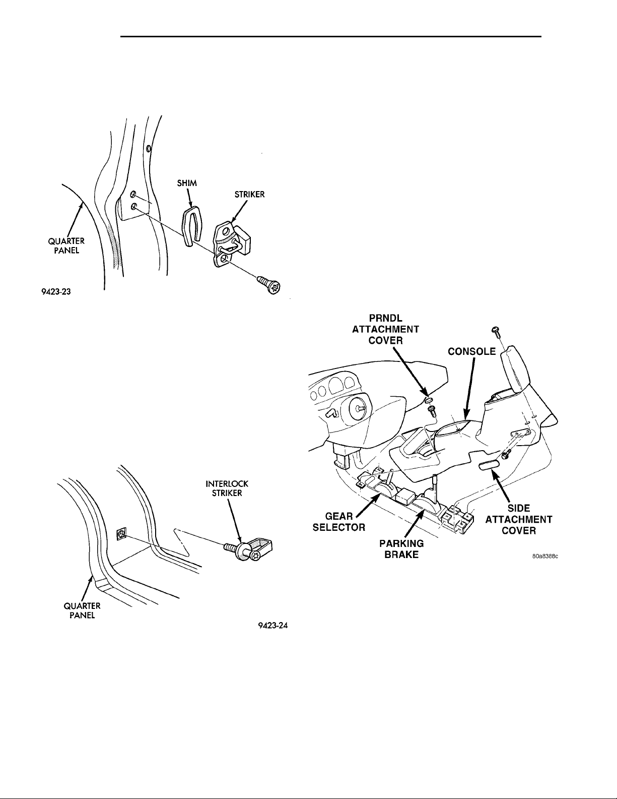
23 - 36 BODY PL
QUARTERPANEL SHIM STRIKER
REMOVAL AND INSTALLATION (Continued)
(2) Remove screws holding door latch striker to
QUARTERPANEL INTERLOCKSTRIKER
B-pillar (Fig. 51).
(3) Separate door latch striker from vehicle.
Fig. 51 Rear Door Latch Striker
INSTALLATION
Reverse the preceding operation.
REAR DOOR INTERLOCK LATCH STRIKER
(2) Remove screw cover plugs over screws just
PRNDL ATTACHMENTCOVERCONSOLESIDE ATTACHMENT COVERPARKING BRAKEGEAR SELECTOR
rearward of cupholders.
(3) Remove screws holding console to floor bracket
just rearward of cupholders (Fig. 53).
(4) Open console storage compartment lid, if so
equipped.
(5) Remove screw cover plugs over screws near
rear of console, if vehicle is equipped with a non–armrest console.
(6) Remove screws holding console to floor bracket.
(7) Snap out side attachment covers, if equipped
(Fig. 53).
(8) Remove side attachment bolts holding rear of
console to floor bracket, if equipped.
(9) Remove shift lever knob, if vehicle is equipped
with a manual transmission.
(10) Lift console upward over gear selector and
park brake handle.
(11) Separate console from vehicle.
REMOVAL
(1) Release door latch and open rear door.
(2) Mark outline of interlock striker on C-pillar to
aid installation.
(3) Remove interlock striker from vehicle (Fig. 52).
Fig. 52 Rear Door Interlock Latch Striker
INSTALLATION
Reverse the preceding operation.
FLOOR CONSOLE
REMOVAL
(1) Fully apply parking brake.
Fig. 53 Floor Console
INSTALLATION
(1) Move floor console into position in vehicle.
(2) Install screws holding console to floor brackets.
(3) Install screw cover plugs.
(4) Install side attachment covers, if equipped.
(5) Install shift lever knob, if vehicle is equipped
with a manual transmission.
(6) Release parking brake and close console storage compartment lid, if so equipped.
DOOR SILL TRIM
REMOVAL
(1) Open door to gain access to sill trim.
Page 37
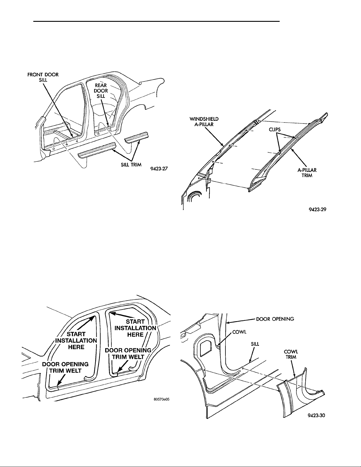
FRONT DOOR SILL REAR DOORSILL SILL TRIM
START INSTALLA-TION HEREDOOR OPENINGTRIM WELTDOOR OPENING TRIMWELTSTART INSTALLATIONHERE
WINDSHIELD A-PILLAR CLIPSA-PILLAR TRIM
PL BODY 23 - 37
REMOVAL AND INSTALLATION (Continued)
(2) Disengage clips holding sill trim to door sill
and door opening flange.
(3) Separate door sill trim from vehicle (Fig. 54).
Fig. 54 Door Sill Trim
INSTALLATION
(1) Position door sill trim on door sill.
(2) Align locating pins on backside of trim panel to
holes in door sill.
(3) Engage clips on trim panel into slots in door sill.
(4) Engage clips on trim panel onto door opening
flange.
(5) Press downward on trim panel to fully engage
all clips.
DOOR OPENING TRIM WELT
REMOVAL
(1) Open door to gain access to trim welt.
(2) Remove door sill trim panel.
(3) Pull trim welt from door opening flange (Fig. 55).
(3) Press trim welt onto door opening flange starting at the paint dot position.
(4) Install door sill trim panel
A-PILLAR TRIM
REMOVAL
(1) Remove instrument panel top cover.
(2) Disengage clips holding trim to A-pillar.
(3) Separate A-pillar trim from vehicle (Fig. 56).
Fig. 56 A-pillar Trim
INSTALLATION
(1) Position A–pillar trim panel to A–pillar.
(2) Align locating pins on backside of trim panel to
mating holes in A–pillar.
(3) Push clips on trim panel into slots in A–pillar.
(4) Install instrument panel top cover.
SIDE COWL TRIM
REMOVAL
(1) Disengage clips holding cowl trim to cowl side
panel.
(2) Separate cowl trim from vehicle (Fig. 57).
DOOR OPENINGCOWL SILL COWL TRIM
Fig. 55 Door Opening Trim Welt
INSTALLATION
(1) Locate paint dot on backside of trim welt.
(2) Position trim welt to vehicle with paint dot in
the appropriate position.
Fig. 57 Side Cowl Trim
INSTALLATION
(1) Position cowl trim panel to inner cowl panel.
Page 38
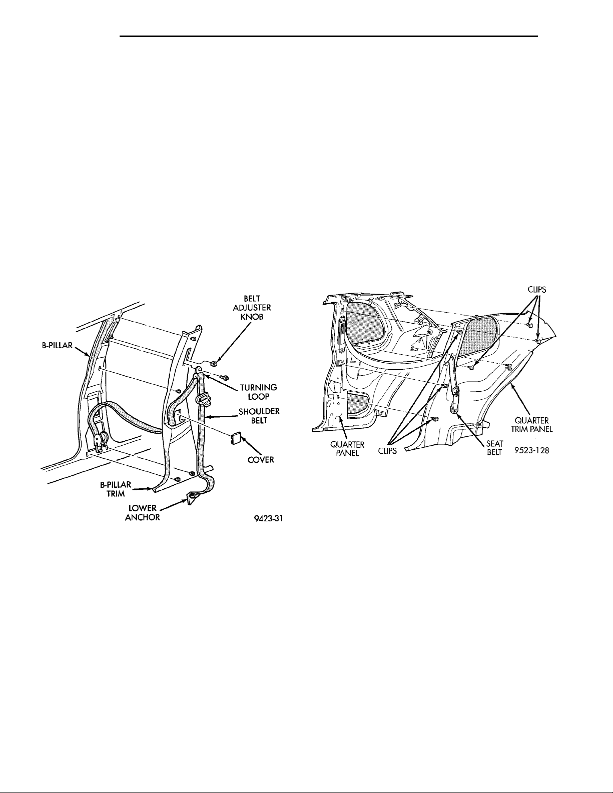
B-PILLAR BELT ADJUSTER KNOBTURNING LOOPSHOULDERBELTCOVERLOWER ANCHORB-PILLAR TRIM
CLIPSQUARTER TRIMPANELSEAT BELTCLIPSQUARTER PANEL
23 - 38 BODY PL
REMOVAL AND INSTALLATION (Continued)
(2) Align locating pins on backside of cowl trim
panel to mating holes in inner cowl panel.
(3) Push clips on trim panel into slots in inner
cowl panel.
B-PILLAR TRIM—4 DOOR
REMOVAL
(1) Remove bolt holding lower seat belt anchor to
floor pan kick-up.
(2) Remove shoulder belt height control knob.
(3) Remove bolt holding turning loop to belt
adjuster (Fig. 58).
(4) Remove access cover from B-pillar trim.
(5) Disengage clips holding trim to B-pillar.
(6) Feed seat belt turning loop and seat belt
through trim panel.
(7) Separate B-pillar trim from vehicle.
QUARTER TRIM PANEL—2 DOOR
REMOVAL
(1) Remove rear seat cushion and back.
(2) Slide lower seat belt anchor cover up the webbing to expose the belt.
(3) Remove bolt holding lower seat belt anchor to
floor.
(4) Separate seat belt from floor.
(5) Remove screw holding coat hook to top of quarter trim panel.
(6) Disengage hidden clips holding quarter trim
panel to inner quarter panel. (Fig. 59)
(7) Separate trim from quarter panel.
(8) Feed seat belt webbing through access hole in
trim panel.
(9) Separate quarter trim panel from vehicle.
Fig. 58 B-pillar Trim
INSTALLATION
(1) Position B–pillar trim panel near B–pillar.
(2) Feed seat belt turning loop and seat belt
through trim panel.
(3) Align locating pins on backside of trim panel to
mating holes in B–pillar.
(4) Push clips on trim panel into slots in B–pillar.
(5) Install access cover to B-pillar trim.
(6) Install bolt holding turning loop to belt
adjuster.
(7) Install shoulder belt height control knob.
(8) Install bolt holding lower seat belt anchor to
floor pan kick-up.
Fig. 59 Quarter Trim Panel
INSTALLATION
(1) Feed seat belt webbing through access hole in
trim panel.
(2) Position trim panel near inner quarter panel.
(3) Align locating pins on backside of trim panel to
mating holes in inner quarter panel.
(4) Push clips on trim panel into slots in inner
quarter panel starting with the clips located near
locating pins.
(5) Install screw holding coat hook to top of quarter trim panel.
(6) Install bolt securing seat belt anchor to floor.
(7) Slide lower seat belt anchor cover down to
cover anchor bolt.
(8) Install rear seat cushion and seat back.
Page 39
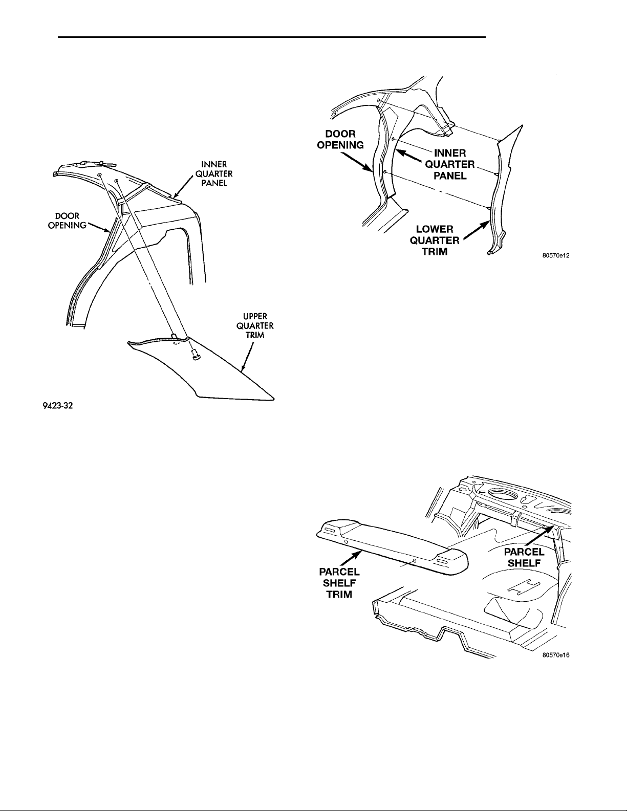
DOOR OPENING INNER QUARTERPANELLOWER QUARTER TRIM
PL BODY 23 - 39
REMOVAL AND INSTALLATION (Continued)
PARCEL SHELFTRIM PARCEL SHELF
UPPER QUARTER TRIM—4 DOOR
DOOR OPENING INNER QUARTER PANELUPPER QUARTER TRIM
REMOVAL
(1) Disengage clips holding trim to upper quarter
panel (Fig. 60).
(2) Separate upper trim panel from vehicle.
Fig. 61 Lower Quarter Trim—4 Door
(4) Press clips on trim panel into slots in inner
quarter panel.
(5) Install rear seat back and cushion.
(6) Install upper quarter trim panel.
Fig. 60 Upper Quarter Trim
INSTALLATION
(1) Check to ensure that electric rear window wiring is positioned correctly in the roof channel provided.
(2) Position trim panel in vehicle.
(3) Align locating pins on backside of trim panel to
mating holes in upper quarter panel.
(4) Push clips on trim panel into slots in upper
quarter panel.
LOWER QUARTER TRIM—4 DOOR
REMOVAL
(1) Remove upper quarter trim panel.
(2) Remove rear seat cushion and back.
(3) Disengage clips holding trim to lower quarter
panel.
(4) Remove seat belt from slot in trim panel.
(5) Separate lower quarter trim from vehicle (Fig.
61).
INSTALLATION
(1) Position lower quarter trim panel to vehicle.
(2) Install seat belt to slot in trim panel.
(3) Align locating pins on backside of trim panel to
mating holes in inner quarter panel.
PARCEL SHELF TRIM
REMOVAL
(1) Remove upper quarter trim from one side of
vehicle.
(2) Remove rear seat cushion and back.
(3) Remove bolts holding rear seat shoulder belt
lower anchors to floor pan.
(4) Disengage seat belt bezel from parcel shelf.
(5) Separate parcel shelf trim from vehicle.
Fig. 62 Parcel Shelf Trim
INSTALLATION
Reverse the preceding operation.
Page 40
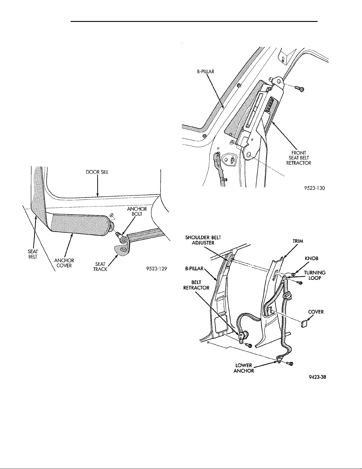
DOOR SILL ANCHOR BOLTSEAT TRACKANCHOR COVERSEAT BELT
B-PILLAR FRONT SEAT BELT RETRAC-TOR
23 - 40 BODY PL
REMOVAL AND INSTALLATION (Continued)
SHOULDER BELT ADJUSTERB-PILLAR BELT RETRACTORLOWER ANCHOR TRIMKNOBTURNINGLOOPCOVER
FRONT OUTBOARD SEAT BELT
REMOVAL
(1) Slide lower seat belt anchor cover upward to
expose bolt.
(2) Remove bolt holding lower anchor bolt to floor
below door sill (Fig. 63).
(3) Separate lower anchor from floor.
(4) Remove rear seat cushion and back.
(5) Remove quarter trim panel.
(6) Guide seat belt webbing through slot in quarter
trim panel.
(7) Disengage wire connector from seat belt retractor.
(8) Remove bolts holding seat belt retractor to
B-pillar (Fig. 64).
(9) Separate seat belt retractor from vehicle.
Fig. 63 Front Outboard Seat Belt Anchor
INSTALLATION
Reverse the preceding operation. Tighten seat belt
anchor bolt to 39 N·m (29 ft. lbs.).
FRONT SEAT BELT BUCKLE
REMOVAL
(1) Move front seat to the forward position.
(2) Remove bolt holding seat belt buckle to seat.
(3) Separate seat belt buckle from seat.
INSTALLATION
Reverse the preceding operation.
Fig. 64 Front Outboard Seat Belt Retractor
(2) Remove bolt holding seat belt retractor to
B-pillar (Fig. 65).
(3) Separate seat belt retractor from vehicle.
FRONT SEAT BELT RETRACTOR
REMOVAL
(1) Remove B-pillar trim.
Fig. 65 Front Seat Belt Retractor
INSTALLATION
Reverse the preceding operation.
Page 41
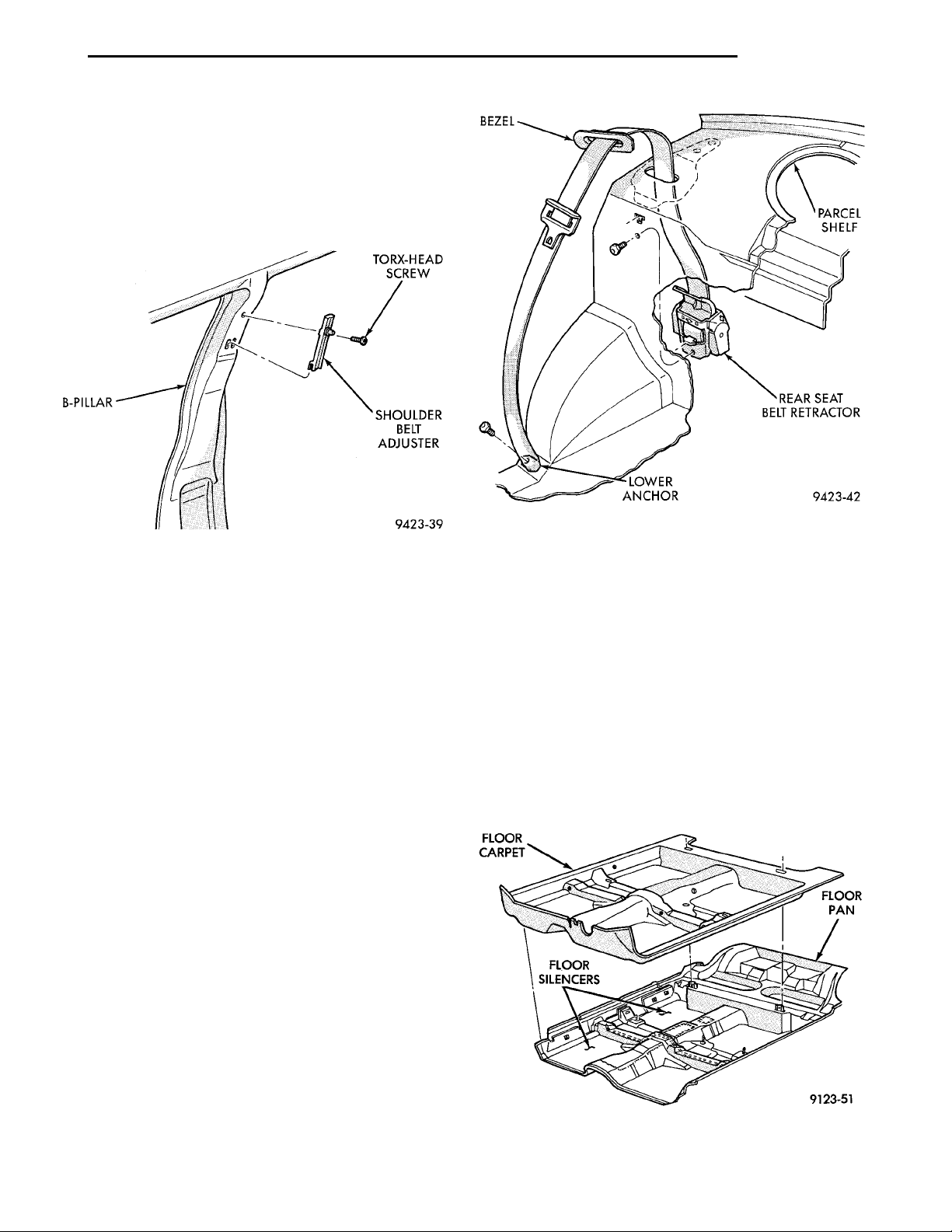
B-PILLAR TORX-HEAD SCREWSHOULDER BELT ADJUSTER
BEZEL PARCEL SHELFREAR SEAT BELT RETRAC-TORLOWER ANCHOR
PL BODY 23 - 41
REMOVAL AND INSTALLATION (Continued)
FRONT SHOULDER BELT ADJUSTER
REMOVAL
(1) Remove B-pillar trim.
(2) Remove bolt holding shoulder belt adjuster to
B-pillar (Fig. 66).
(3) Separate shoulder belt adjuster from vehicle.
Fig. 66 Front Shoulder Belt Adjuster
INSTALLATION
Reverse the preceding operation.
REAR SEAT BELT BUCKLE
REMOVAL
(1) Remove rear seat cushion.
(2) Remove rear seat back.
(3) Separate rear seat belt buckle from vehicle.
INSTALLATION
Reverse the preceding operation.
REAR SEAT BELT RETRACTOR
REMOVAL
(1) Remove rear seat cushion and back.
(2) Remove seat belt bezel from parcel shelf cover.
(3) Remove rear seat closure panel silencer pad as
necessary to gain access to retractor.
(4) Remove bolt holding seat belt lower anchor to
floor.
(5) Remove bolt holding retractor to rear seat closure panel (Fig. 67).
(6) Push seat belt bezel and buckle stab through
access hole in parcel shelf.
(7) From in luggage compartment, separate rear
seat belt retractor from vehicle.
Fig. 67 Rear Seat Belt Retractor
CARPET
REMOVAL
(1) Remove front seats.
(2) Remove rear seat cushion.
(3) Remove bolts holding front seat belt lower
anchors to floor (Fig. 68).
(4) Remove door sill trim covers.
(5) Remove cowl trim covers.
(6) Remove center floor console.
(7) Remove trunk release assist handle.
FLOOR CARPET FLOOR PAN
(8) Remove lower fasteners from B–pillar trim
FLOOR SILENCERS
panel.
(9) Pull carpet from behind trim panel.
(10) Fold carpet in half toward rear seat.
(11) Remove carpet through rear door opening.
INSTALLATION
Reverse the preceding operation.
Fig. 68 Carpet
Page 42
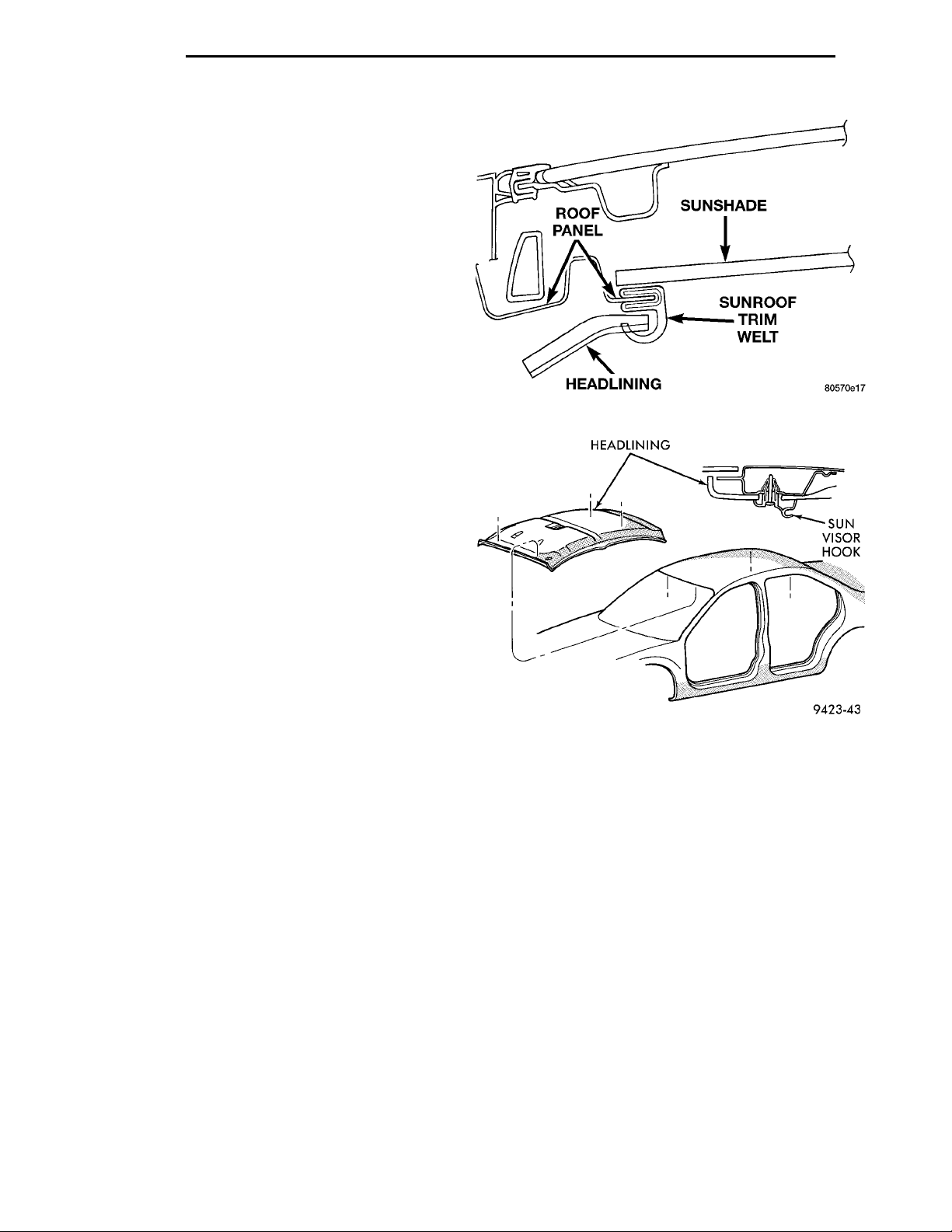
HEADLINING SUN VISORHOOK
SUNSHADESUNROOF TRIM WELTHEADLININGROOF PANEL
23 - 42 BODY PL
REMOVAL AND INSTALLATION (Continued)
INSTALLATION
(1) Install carpet through rear door opening.
(2) Unfold carpet.
(3) Tuck carpet behind trim panel.
(4) Install lower fasteners holding B–pillar trim
panel.
(5) Install trunk release assist handle.
(6) Install center floor console.
(7) Install cowl trim covers.
(8) Install door sill trim covers.
(9) Install bolts holding front seat belt lower
anchors to floor.
(10) Install rear seat cushion.
(11) Install front seats.
HEADLINING
REMOVAL
(1) Remove screws holding sun visors to roof
header panel.
(2) Disengage wire connector from lighted vanity
mirror, if so equipped.
(3) Separate sun visors from vehicle.
(4) Remove A-pillar trim covers.
(5) Remove B-pillar trim panels, if vehicle is a 4
door.
(6) Remove (upper) quarter panel trim panels.
(7) Remove assist handles, if so equipped.
(8) Remove sun visor hooks.
(9) Remove coat hooks, if vehicle is a 4 door.
(10) If vehicle is equipped with a sunroof;
(a) Open sunroof.
(b) Remove trim welt around sunroof opening
(Fig. 69).
(c) Remove sunroof switch pod.
(d) Disconnect sunroof switch pod wire connec-
tors.
(e) Remove screw holding switch pod retainer to
roof.
(11) Remove push–in fastener at rear of headlin-
ing.
(12) Disengage dome lamp wire connector, at rear
of headlining.
(13) Remove push–in fastener holding wiring to
C–pillar.
(14) Remove headlining through door opening (Fig.
70).
INSTALLATION
(1) Position headlining in vehicle.
(2) Install sun visor hooks.
(3) Install coat hooks, if vehicle is a 4 door.
(4) Install push–in fastener at rear of headlining.
(5) Install assist handles, if so equipped.
(6) Install push–in fastener holding headliner wir-
ing to C–pillar.
(7) Engage dome lamp wire connector, at rear of
headlining.
(8) If vehicle is equipped with a sunroof;
roof.
(Fig. 69).
(9) Install (upper) quarter panel trim panel.
(10) Install B-pillar trim panels, if vehicle is a 4
door.
(11) Install A-pillar trim covers.
(12) Install sun visors, lighted vanity mirror wire
connector, if so equipped, and screws holding sun
visors to roof header panel.
Fig. 69 Sunroof Opening Trim Welt
Fig. 70 Headlining
(a) Install screw holding switch pod retainer to
(b) Connect sunroof switch pod wire connectors.
(c) Install sunroof switch pod.
(d) Install trim welt around sunroof opening
(e) Close sunroof.
Page 43
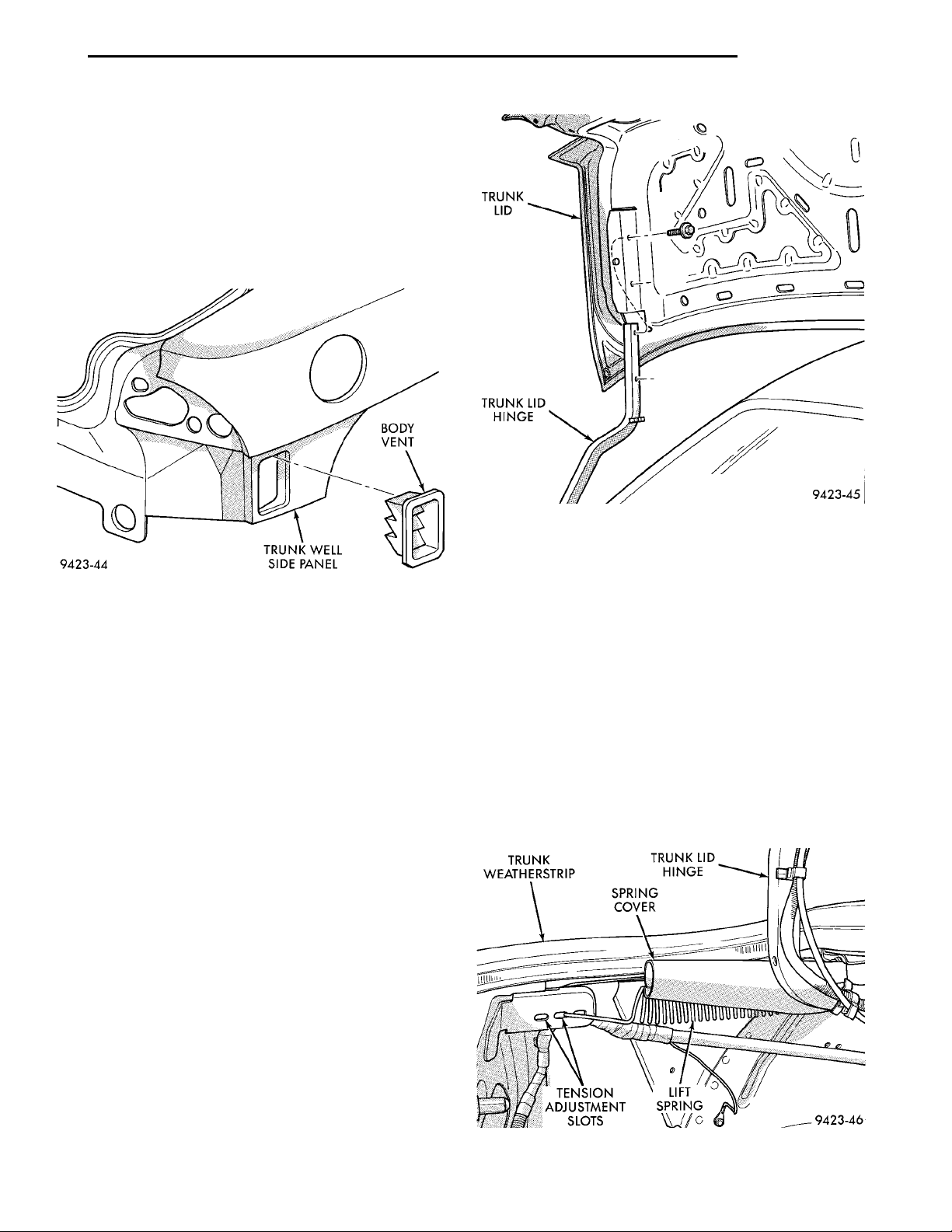
BODY VENTTRUNK WELL SIDE PANEL
TRUNK LIDTRUNK LID HINGE
PL BODY 23 - 43
TRUNK WEATHER-STRIP TRUNK LID HINGESPRING COVERLIFT SPRINGTENSION ADJUST-MENT SLOTS
REMOVAL AND INSTALLATION (Continued)
BODY VENT
REMOVAL
(1) Hoist rear end of vehicle and support on safety
stands.
(2) From behind rear bumper fascia below quarter
panel, disengage clips holding body vent to trunk
well.
(3) Separate body vent from vehicle (Fig. 71).
Fig. 71 Body Vent
INSTALLATION
Reverse the preceding operation.
TRUNK LID
REMOVAL
(1) Release trunk latch and open trunk lid.
(2) Mark bolt locations on inside of trunk lid to aid
installation.
(3) Disengage clips holding wire harness and
trunk lid release cable to trunk lid.
(4) Disengage wire connector and release cable
from trunk latch.
(5) Remove bolts holding top of hinge to trunk lid
(Fig. 72).
(6) With aid from a helper, remove bolts holding
bottom of hinge to trunk lid.
(7) Separate trunk lid from vehicle.
Fig. 72 Trunk Lid
(7) Install clips to hold wire harness and cable to
trunk lid.
TRUNK LID LIFT SPRINGS
REMOVAL
WARNING: USE EYE AND HAND PROTECTION
WHEN REMOVING SPRINGS, PERSONAL CAN
RESULT.
(1) Release trunk and open trunk lid.
(2) Support trunk lid on a suitable prop device.
(3) Pull split cover from lift spring (Fig. 73).
(4) Using a common plier, disengage spring from
adjustment slot under trunk opening side trough.
(5) Disengage spring from trunk lid hinge.
INSTALLATION
(1) Place trunk lid in position on vehicle.
(2) With aid from a helper, install bolts to hold bottom of hinge to trunk lid.
(3) Install bolts to hold top of hinge to trunk lid.
(4) Align trunk lid to achieve equal spacing on all
sides and flush across gaps.
(5) Verify trunk lid operation and sealing.
(6) Connect wire connector and release cable on
latch.
Fig. 73 Trunk Lid Lift Springs
Page 44
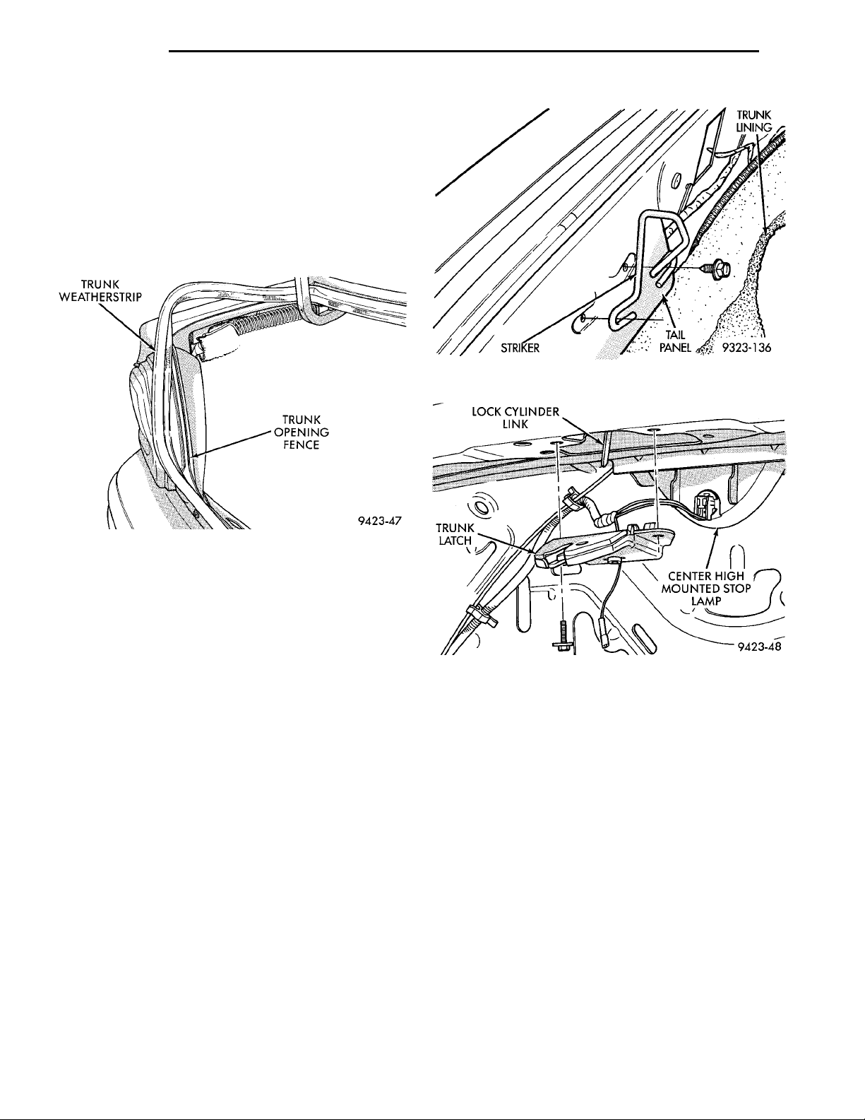
23 - 44 BODY PL
TRUNK WEATHER-STRIP TRUNK OPENING FENCE
TRUNKLATCHLOCK CYLINDER LINK CENTER HIGHMOUNTED STOPLAMP
REMOVAL AND INSTALLATION (Continued)
INSTALLATION
Reverse the preceding operation.
TRUNK WEATHERSTRIP
REMOVAL
(1) Release trunk lid latch and open trunk lid.
(2) Pull trunk lid weatherstrip form trunk opening
fence (Fig. 74).
(3) Separate weatherstrip from vehicle.
Fig. 75 Trunk Latch Striker
Fig. 74 Trunk Weatherstrip
INSTALLATION
Reverse the preceding operation.
TRUNK LATCH STRIKER
REMOVAL
(1) Release trunk lid latch and open trunk lid.
(2) Remove push-in fasteners holding trunk lining
to tail panel.
(3) Separate trunk lining from tail panel.
(4) Remove bolts holding trunk latch striker to tail
panel (Fig. 75).
(5) Separate striker from vehicle.
INSTALLATION
Reverse the preceding operation.
TRUNK LATCH
REMOVAL
(1) Release trunk lid latch and open trunk lid.
(2) Remove bolts holding trunk latch to trunk lid
(Fig. 76).
(3) Separate trunk latch from trunk lid.
(4) Disconnect remote trunk latch release cable
form trunk latch.
(5) Disengage trunk ajar switch connector from
latch.
(6) Separate latch from vehicle.
Fig. 76 Trunk Latch
INSTALLATION
(1) Position latch in vehicle and engage trunk ajar
switch connector to latch.
(2) Connect remote trunk latch release cable to
trunk latch.
(3) Install bolts holding trunk latch to trunk lid.
TRUNK LOCK CYLINDER
REMOVAL
(1) Remove trunk latch.
(2) Remove clip holding trunk lock cylinder to
trunk lid.
(3) Pull lock cylinder from trunk lid (Fig. 77).
INSTALLATION
Reverse the preceding operation.
Page 45
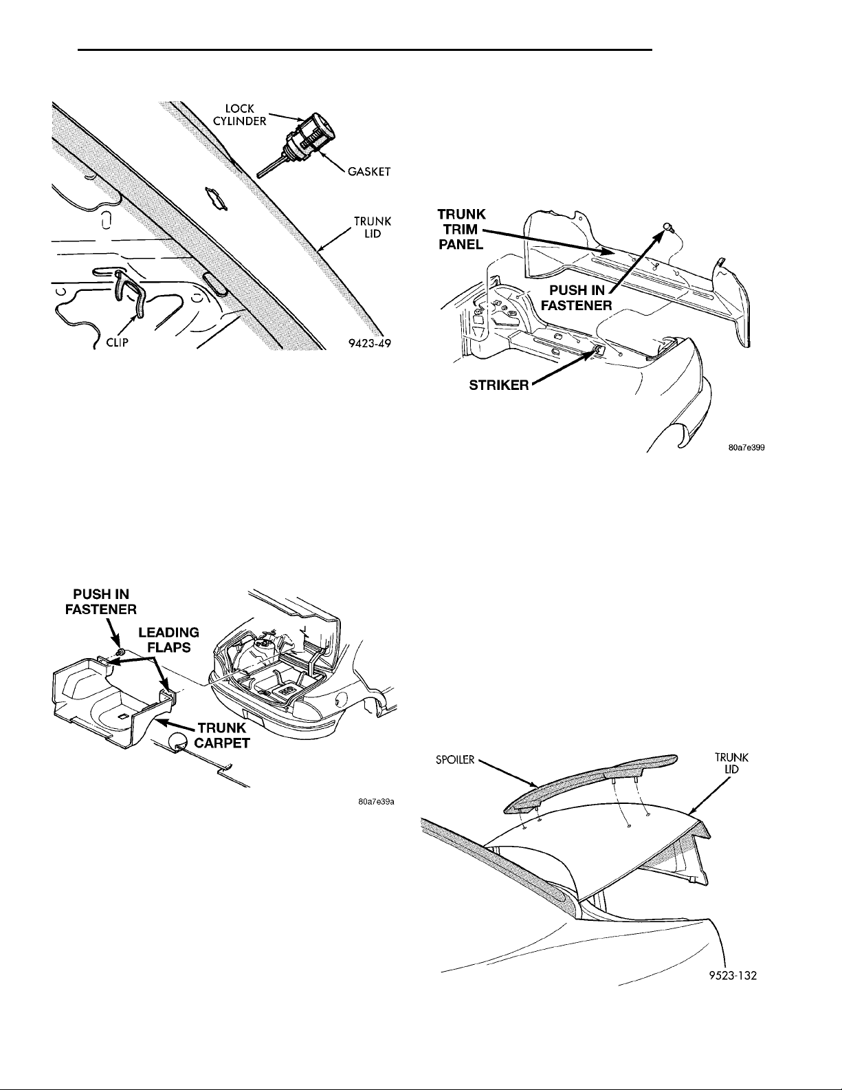
LOCK CYLIN-DER GASKETTRUNK LID
PL BODY 23 - 45
REMOVAL AND INSTALLATION (Continued)
PUSH IN FASTENERLEADING FLAPSTRUNK CARPET
Fig. 77 Trunk Lock Cylinder
TRUNK CARPET
REMOVAL
(1) Remove push in fasteners holding carpet to
shelf panel. Fasteners are accessed from inside the
vehicle (Fig. 78).
(2) Pull out leading flaps of the carpet through the
opening from the shelf panel.
(3) Pull carpet from under the springs.
(4) Remove trunk carpet from vehicle.
TRUNK TRIM PANEL
TRUNK TRIM PANELPUSH IN FASTENERSTRIKER
SPOILER TRUNK LID
Removal
(1) Remove fasteners holding trunk trim panel to
vehicle (Fig. 79).
(2) Remove trunk trim panel from vehicle.
Fig. 79 Trunk Trim Panel
Installation
(1) Position panel to deck lid over the stricker.
(2) Install push in fasteners.
(3) Position and tuck the upper flange into existing
trim panel on both sides.
(4) Push the corners in place under seal.
(5) Seat the lower edges of the carpet and smooth
out.
Fig. 78 Trunk Carpet
INSTALLATION
(1) Place carpet in truck and smooth out.
(2) Tuck both sides of the carpet ends under
springs.
(3) Position the leading flaps of the carpet through
the opening onto the shelf panel.
(4) Install push in fasteners to secure the carpet to
shelf panel (install fasteners from inside the vehicle).
(5) Overlap the slits in the back of the carpet so
the center section lays over the outer sections.
REAR SPOILER
REMOVAL
(1) Release trunk latch and open trunk lid.
(2) Remove nuts holding spoiler to trunk lid.
(3) Separate spoiler from trunk lid (Fig. 80).
Fig. 80 Rear Spoiler
Page 46
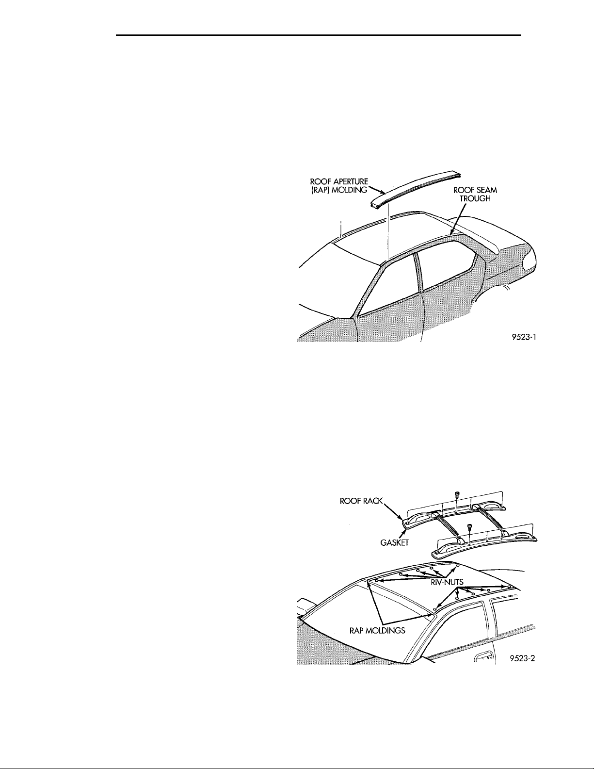
23 - 46 BODY PL
REMOVAL AND INSTALLATION (Continued)
INSTALLATION
Apply water sealing putty around spoiler mounting
studs and reverse the preceding operation.
ROOF APERTURE (RAP) MOLDING
The RAP molding is set in urethane adhesive. The
RAP molding is difficult to salvage during removal.
Verify part availability before proceeding with
removal procedure. The temperature in the work
area and the vehicle should be at least 21°C (70°F) to
avoid damaging the rear window and windshield
moldings. Apply masking tape to surrounding area of
the RAP molding to protect the finish.
REMOVAL
(1) Using a trim stick, gently lift rear window
molding upward to gain access to end of RAP molding.
(2) Using a sharp hook tool, pierce the rear end of
the molding.
(3) Lift the rear of the RAP molding upward until
it clears the rear window molding.
(4) Using a common plier, pull the RAP molding
forward to separate molding from urethane bonding.
(5) Separate RAP molding from vehicle.
INSTALLATION
(1) Using a sharpened trim stick, scrape urethane
bonding material from the roof seam trough.
(2) Using touch-up paint, repair scratches in roof
seam trough to prevent corrosion.
(3) Inspect the bottom of the roof seam trough for
gaps in caulking. Repair gaps with suitable seam
sealer following manufacturers instructions.
(4) Apply black-out primer to bottom of roof seam
trough. Allow at lease three minutes before bonding
is applied.
(5) Install RAP molding into the roof seam trough
and position molding so both ends are covered by the
glass moldings. If the molding will not lay flat on the
bottom of the trough, trim the ends of the molding
until proper fit achieved.
(6) Using a suitable marking pencil, mark an
index line across the RAP molding and the adjacent
surfaces.
(7) Remove the RAP molding from the roof seam
trough.
(8) Applya5mm(0.2 in.) bead of urethane adhesive on the bottom/center of the trough along the
entire length.
(9) Place RAP molding in position in roof seam
trough (Fig. 81).
(10) Insert both ends of RAP molding under glass
moldings.
(11) Align index marks across trough and molding.
(12) Gently press RAP molding into urethane
adhesive until molding lays smooth and flat.
ROOF APERTURE (RAP)MOLDING ROOF SEAM TROUGH
ROOF RACK GASKET RIV-NUTSRAP MOLDINGS
(13) Remove protective tape from around the RAP
molding.
(14) Clean excess urethane from exterior with
Mopar, Super Clean or equivalent.
(15) Apply a length of 50 mm (2 in.) masking tape
over the RAP molding to retain the molding until the
urethane adhesive is cured. Curing time for most
urethane adhesive is at least 24 hours.
Fig. 81 RAP Molding
ROOF RACK
The roof rack insulator gasket is bonded to the
base of the side rail. If the gasket comes loose during
servicing, secure the gasket to the side rail with
Mopar, Bond-all Gel Adhesive or equivalent.
REMOVAL
(1) Remove screws holding roof rack side rails to
the roof panel (Fig. 82).
(2) Separate roof rack from vehicle.
Fig. 82 Roof Rack
INSTALLATION
Reverse the preceding operation.
Page 47
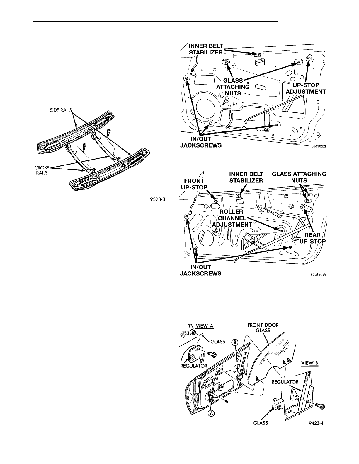
SIDE RAILS CROSS RAILS
PL BODY 23 - 47
INNER BELT STABI-LIZER GLASSATTACHINGNUTS UP-STOP ADJUST-MENTIN/OUT JACKSCREWS
FRONT UP-STOPROLLER CHANNEL ADJUST-MENT INNER BELT STABI-LIZER
REAR UP-STOPIN/OUT JACK-SCREWS
VIEW AGLASSREGULATOR FRONT DOOR GLASS VIEW BREGULATORGLASS
GLASS
ATTACHING
NUTS
REMOVAL AND INSTALLATION (Continued)
ROOF RACK CROSS RAILS
The roof rack side rail do not have to be removed
to replace the cross rails.
REMOVAL
(1) Remove screws holding cross rail to the side
rails.
(2) Separate the cross rail from the roof rack.
Fig. 84 Glass Adjustment—4 Door
(7) Tighten all fasteners.
Fig. 83 Roof Rack Cross Rails
INSTALLATION
Reverse the preceding operation.
ADJUSTMENTS
FRONT DOOR GLASS ADJUSTMENT
UP-STOP ADJUSTMENTS
(1) Remove door trim panel.
(2) Remove water shield as necessary to gain
access to adjuster.
(3) Loosen up-stop nut.
(4) Close door and raise door glass.
(5) Adjust up-stop to achieve proper glass height.
(6) Adjust glass so that a piece of paper can be pulled
between the glass and weatherstrip with some tension.
NOTE: The top edge of the door glass should be
beneath the lip of the weatherstrip
(7) Tighten fasteners.
TOP OF GLASS—INBOARD/OUTBOARD ADJUSTMENTS
(1) Remove door trim panel.
(2) Remove water shield as necessary to gain
access to adjusters.
(3) Using a Snap-ont flare-nut socket (FRXM10),
loosen the lower jack-screw jamb-nuts.
(4) Close door and raise glass.
(5) Using a suitable allen-wrench, rotate jackscrews to achieve proper in/out positioning at the top
edge of the glass.
(6) Adjust glass so that a piece of paper can be pulled
between the glass and weatherstrip with some tension.
Fig. 85 Glass Adjustment—2 Door
GLASS—FRONT/REAR ADJUSTMENT
(1) Remove door trim panel and water shield.
(2) Lower door glass to bottom of travel to gain
access to glass attachments. (Fig. 86)
Fig. 86 Front door glass
Page 48
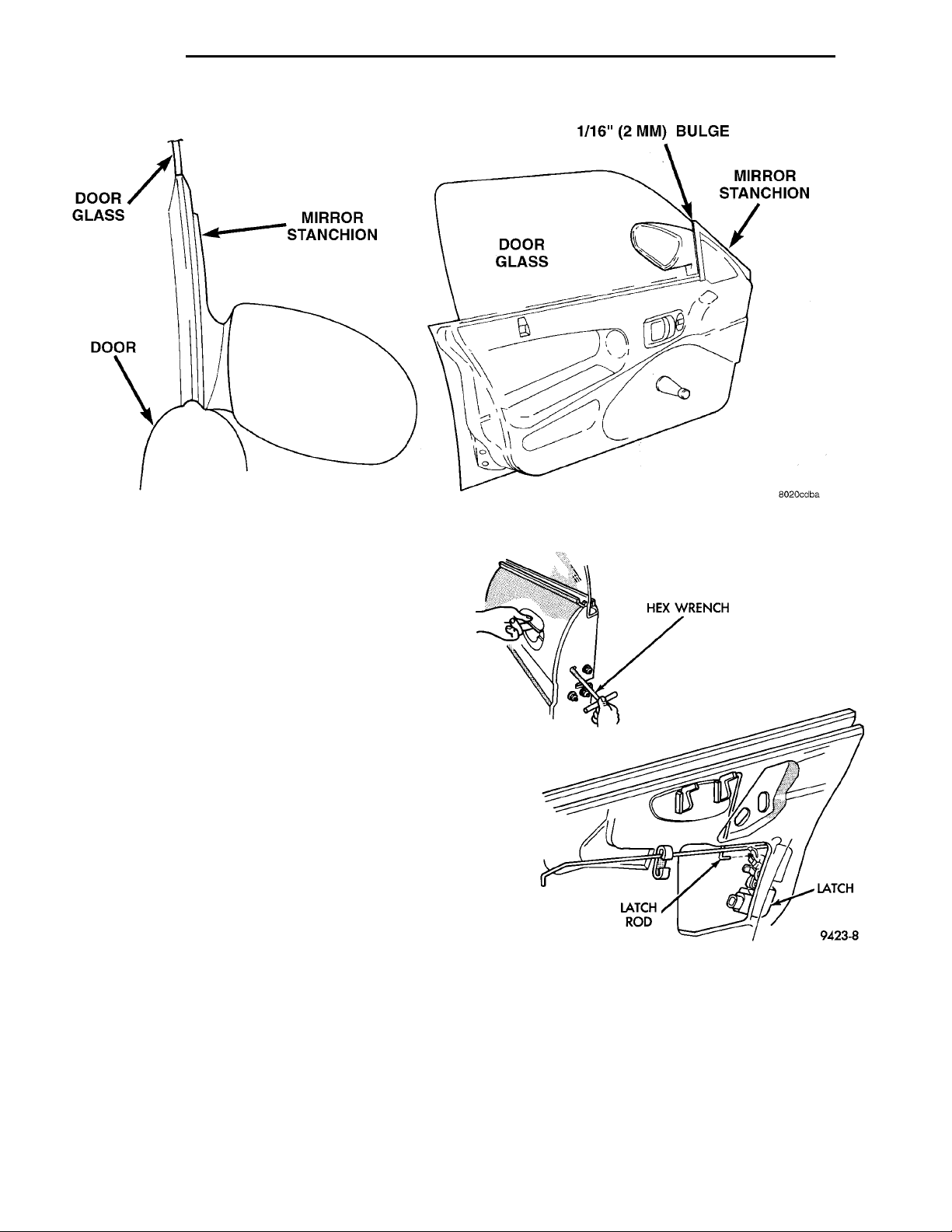
23 - 48 BODY PL
ADJUSTMENTS (Continued)
HEX WRENCH LATCHLATCH ROD
Fig. 87 Front/Rear Glass Position
(3) Loosen three glass attachment bolts.
(4) Raise glass to top of travel and adjust glass to
fit the B-pillar seal. Glass to B-pillar applique gap
should be approximately 13mm (1/2 inch).
(5) Tighten the two accessible glass fasteners in
the full up position.
(6) Lower door glass to the full down position and
tighten the remaining glass fastener.
(7) Raise glass to top of travel and verify positioning. (Fig. 87)
FRONT DOOR LATCH ADJUSTMENT
(1) Insert a hex-wrench through the elongated hole
in the door end frame near the latch striker opening
(Fig. 88).
(2) Loosen socket head screw on the side of the
latch linkage.
(3) Lift upward on outside door handle and release
it.
(4) Tighten socket head screw on latch.
(5) Verify latch operation.
REAR DOOR GLASS ADJUSTMENT
UP-STOP ADJUSTMENTS
(1) Remove door trim panel.
(2) Remove water shield as necessary to gain
access to adjusters.
(3) Using a Snap-ont flare-nut socket (FRXM10),
loosen up- stop eccentric jamb-nut (Fig. 89).
(4) Using a suitable hex-wrench, rotate up-stop
eccentric to achieve proper glass height.
Fig. 88 Door Latch Adjustment
(5) Adjust glass so that a piece of paper can be
pulled between the glass and weatherstrip with some
tension.
TOP OF GLASS—INBOARD/OUTBOARD ADJUSTMENTS
(1) Remove door trim panel.
(2) Remove water shield as necessary to gain
access to adjusters.
Page 49
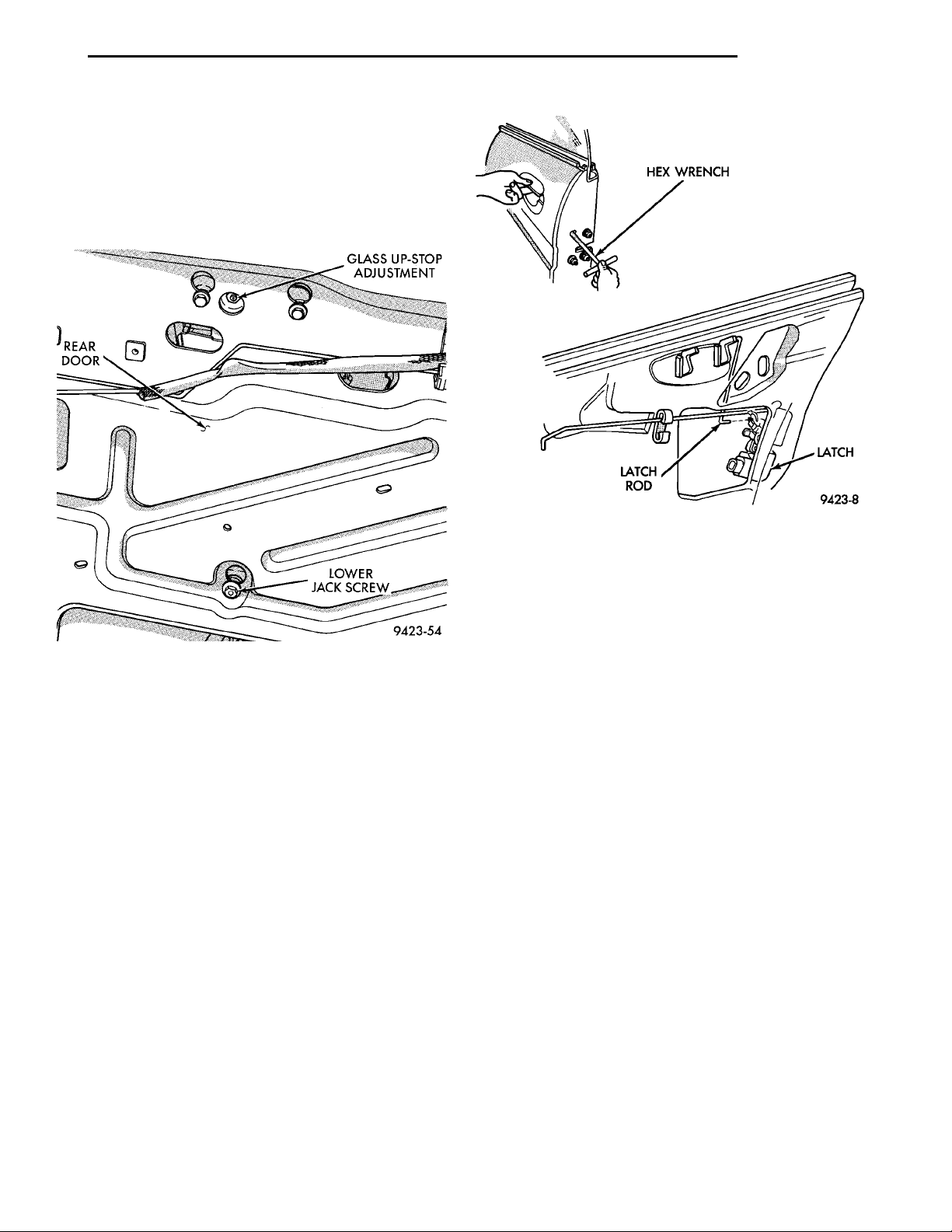
HEX WRENCH LATCHLATCH ROD
PL BODY 23 - 49
ADJUSTMENTS (Continued)
(3) Using a Snap-ont flare-nut socket (FRXM10),
loosen the lower jack-screw jamb-nuts (Fig. 89).
(4) Using a suitable hex-wrench, rotate jack-screws
to achieve proper tension at the top of the glass.
(5) Adjust glass so that a piece of paper can be
pulled between the glass and weatherstrip with some
tension.
Fig. 89 Rear Door Glass Adjustment—Typical
REAR DOOR LATCH ADJUSTMENT
(1) Insert a hex-wrench through the elongated hole
in the door end frame near the latch striker opening
(Fig. 90).
(2) Loosen socket head screw on the side of the
latch linkage.
(3) Lift upward on outside door handle and release
it.
(4) Tighten socket head screw on latch.
(5) Verify latch operation.
SPECIFICATIONS
BODY LUBRICATION SPECIFICATIONS
LUBRICATION REQUIREMENTS
Body mechanisms and linkages should be
inspected, cleaned, and lubricated, as required, to
maintain ease of operation and to provide protection
against rust and wear. When performing other
underhood services, the hood latch release mechanism and safety catch should be inspected, cleaned,
and lubricated. During the winter season, external
door lock cylinders should be lubricated to assure
proper operation when exposed to water and ice.
Fig. 90 Door Latch Adjustment
Prior to the application of any lubricant, the parts
concerned should be wiped clean to remove dust and
grit. If necessary, a suitable solvent can be used to
clean the item to be lubricated. After lubricating a
component, any excess oil or grease should be
removed.
LUBRICANT APPLICATION
DOOR LOCK CYLINDERS
(1) Apply a small amount of lubricant directly into
the lock cylinder.
(2) Apply a small amount of lubricant to the key.
(3) Insert key into lock cylinder and cycle the
mechanism from the locked to the unlocked position.
NOTE: Do not add more lubricant.
(4) Cycle the lock cylinder mechanism several
times to allow the lubricant to flow throughout the
cylinder.
(5) Wipe all lubricant from exterior of lock cylinder
and key.
ALL OTHER BODY MECHANISMS
(1) Clean component as described above.
(2) Apply specified lubricant to all pivoting and
sliding contact areas of component.
Page 50
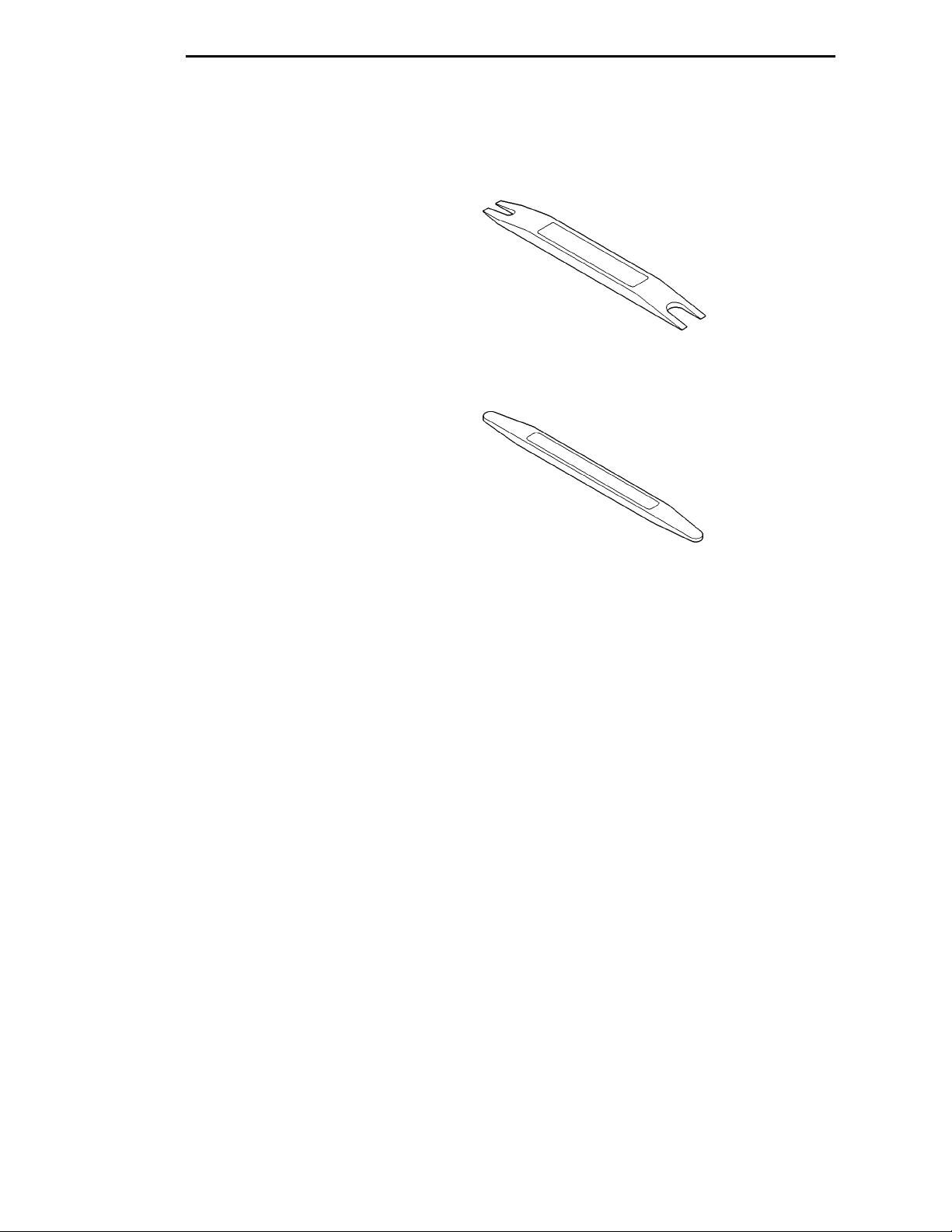
23 - 50 BODY PL
SPECIFICATIONS (Continued)
LUBRICANT USAGE
ENGINE OIL
• Door Hinges—Hinge Pin and Pivot Contact
Areas
• Hood Hinges—Pivot Points
• Liftgate Hinges
• Trunk Lid Hinges
MOPARTSPRAY WHITE LUBE OR EQUIVALENT
• Door Check Straps
• Liftgate Latches
• Liftgate Prop Pivots
• Ash Receiver
• Fuel Filler Door Remote Control Latch Mecha-
nism
• Parking Brake Mechanism
• Sliding Seat Tracks
• Trunk Latch
MOPARTMULTI–PURPOSE GREASE OR
EQUIVALENT
• All Other Hood Mechanisms
MOPARTLOCK CYLINDER LUBRICANT OR
EQUIVALENT
• Door Lock Cylinders
• Trunk Lock Cylinder
SPECIAL TOOLS
BODY
REMOVER, MOLDINGS C 4829
STICK, TRIM C4755
 Loading...