

Page 1

PL TIRES AND WHEELS 22 - 1
TIRES AND WHEELS
CONTENTS
page page
TIRES ................................. 1 WHEELS ............................... 9
TIRES
INDEX
page page
DESCRIPTION AND OPERATION
RADIAL-PLY TIRES ...................... 2
REPLACEMENT TIRES ................... 3
SPARE TIRE (TEMPORARY) ............... 2
TIRE INFLATION PRESSURES ............. 2
TIRE INFORMATION ..................... 1
TIRE PRESSURE FOR HIGH—SPEED
OPERATION .......................... 3
DIAGNOSIS AND TESTING
LEAD CORRECTION CHART ............... 4
PRESSURE GAUGES .................... 3
DESCRIPTION AND OPERATION
TIRE INFORMATION
Tires are designed and engineered for each specific
vehicle. They provide the best overall performance
for normal operation. The ride and handling characteristics match the vehicle’s requirements. With
proper care they will give excellent reliability, traction, skid resistance, and tread life.
Driving habits have more effect on tire life than
any other factor. Careful drivers will obtain, in most
cases, much greater mileage than severe use or careless drivers. A few of the driving habits which will
shorten the life of any tire are:
• Rapid acceleration
• Severe application of brakes
• High-speed driving
• Taking turns at excessive speeds
• Striking curbs and other obstacles
Radial ply tires are more prone to irregular tread
wear. It is important to follow the tire rotation interval shown in the section on Tire Rotation. This will
help to achieve a greater tread-life potential.
TIRE NOISE OR VIBRATION ............... 4
TIRE WEAR PATTERNS ................... 3
TREAD WEAR INDICATORS ............... 3
SERVICE PROCEDURES
REPAIRING TIRE LEAKS .................. 6
TIRE AND WHEEL MATCH MOUNTING ....... 6
TIRE AND WHEEL ROTATION .............. 6
CLEANING AND INSPECTION
CLEANING OF TIRES .................... 7
SPECIFICATIONS
TIRE SPECIFICATIONS ................... 8
TIRE IDENTIFICATION
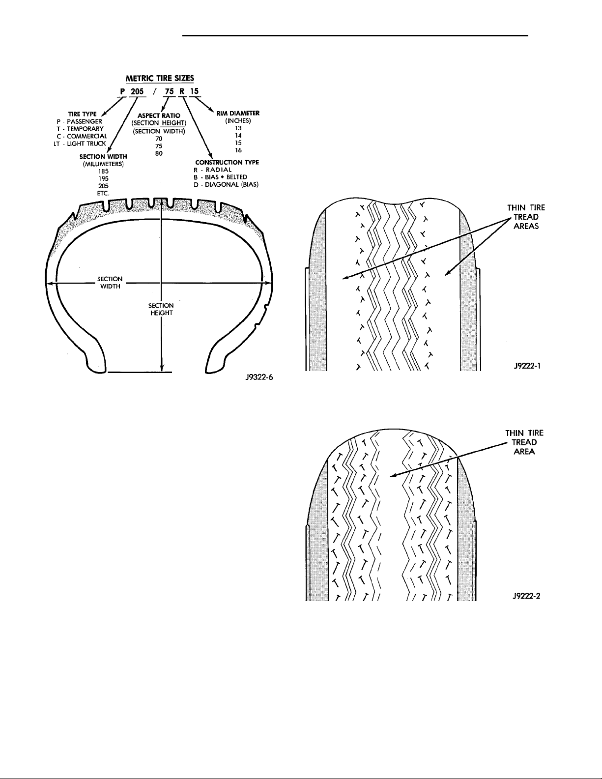
Tire type, size, aspect ratio and speed rating are
encoded in the letters and numbers imprinted on the
side wall of the tire. Refer to the chart to decipher
the tire identification code (Fig. 1).
Performance tires will have a speed rating letter
after the aspect ratio number. The speed rating is not
always printed on the tire sidewall. The letter S indicates that the tire is speed rated up to 112 mph.
• Q up to 100 mph
• T up to 118 mph
• U up to 124 mph
• H up to 130 mph
• V up to 149 mph
• Z more than 149 mph (consult the tire manu-
facturer for the specific speed rating)
An All Season type tire will have either M+S,M
&SorM-S(indicating mud and snow traction)
imprinted on the side wall.
TIRE CHAINS
This vehicle was not designed to allow the use of
snow chains on the tires. If snow chains are installed
on the tires, there may not be sufficient clearance
under all driving conditions. This may cause damage
Page 2
METRIC TIRE SIZESP 205 /75 R15TIRE TYPEP - PASSENGERT - TEMPORARYC - COMMERCIALLT - LIGHT TRUCKSECTION WIDTH(MILLIMETERS)185195205ETC. ASPECT RATIO(SECTION HEIGHT)(SECTION WIDTH)707580 CONSTRUCTION TYPER - RADIALB - BIAS • BELTEDD - DIAGONAL (BIAS)RIM DIAMETER(INCHES)13141516SECTIONWIDTH SECTIONHEIGHT
THIN TIRE THREADAREAS
THIN TIRE THREAD AREA
22 - 2 TIRES AND WHEELS PL
DESCRIPTION AND OPERATION (Continued)
SPARE TIRE (TEMPORARY)
The temporary spare tire is designed for emergency use only. The original tire should be repaired
and reinstalled at the first opportunity, or a new tire
purchased. Do not exceed speeds of 50 MPH. Refer to
Owner’s Manual for complete details.
TIRE INFLATION PRESSURES
Under inflation causes rapid shoulder wear, tire
flexing, and can result in tire failure (Fig. 2).
Fig. 1 Tire Identification
to the body and/or suspension components of the
vehicle.
RADIAL-PLY TIRES
Radial-ply tires improve handling, tread life, ride
quality and decrease rolling resistance.
Radial-ply tires must always be used in sets of four
and under no circumstances should they be used on
the front only. They may be mixed with temporary
spare tires when necessary. A maximum speed of 50
MPH is recommended while a temporary spare is in
use.
Radial-ply tires have the same load-carrying capacity as other types of tires of the same size. They also
use the same recommended inflation pressures.
The use of oversized tires, either in the front or
rear of the vehicle, can cause vehicle drive train failure. This could also cause inaccurate wheel speed
signals when the vehicle is equipped with Anti-Lock
Brakes.
It is recommended that tires from different manufactures NOT be mixed. The proper tire pressure
should be maintained on all four tires. For proper
tire pressure refer to the Tire Inflation Pressure
Chart provided with the vehicle.
Fig. 2 Under Inflation Wear
Over inflation causes rapid center wear and loss of
the tire’s ability to cushion shocks (Fig. 3).
Fig. 3 Over Inflation Wear
Improper inflation can cause:
• Uneven wear patterns
• Reduced tread life
• Reduced fuel economy
• Unsatisfactory ride
• The vehicle to drift.
For proper tire pressure specification refer to the
Tire Inflation Pressure Chart Placard provided with
the vehicle.
Page 3
THREAD ACCEPTABLE THREAD UNACCEPTABLEWEAR INDICATOR
PL TIRES AND WHEELS 22 - 3
DESCRIPTION AND OPERATION (Continued)
Tire pressures have been chosen to provide safe
operation, vehicle stability, and a smooth ride. Tire
pressure should be checked cold once per month.
Check tire pressure more frequently when the
weather temperature varies widely. Tire pressure will
decrease when the outdoor temperature drops.
Inflation pressures specified on the placard are
always the cold inflation pressure of the tire. Cold
inflation pressure is obtained after the vehicle has
not been operated for at least 3 hours, or the vehicle
is driven less than one mile after being inoperative
for 3 hours. Tire inflation pressures may increase
from 2 to 6 pounds per square inch (psi) during operation. Do not reduce this normal pressure build-up.
WARNING: OVER OR UNDER INFLATED TIRES
CAN AFFECT VEHICLE HANDLING. THE TIRE CAN
FAIL SUDDENLY, RESULTING IN LOSS OF VEHICLE
CONTROL.
TIRE PRESSURE FOR HIGH—SPEED OPERATION
Chrysler Corporation advocates driving at safe
speeds within posted speed limits. Where speed limits allow the vehicle to be driven at high speeds, correct tire inflation pressure is very important. For
speeds up to and including 75 mph (120 km/h), tires
must be inflated to the pressures shown on the tire
placard. For continuous speeds in excess of 75 mph
(120 km/h), tires must be inflated to the maximum
pressure specified on the tire sidewall.
Vehicles loaded to the maximum capacity should
not be driven at continuous speeds above 75 mph
(120 km/h).
For emergency vehicles that are driven at speeds
over 90 mph (144 km/h), special high-speed tires
must be used. Consult tire manufacturer for correct
inflation pressure recommendations.
The use of oversize tires not listed in the specification charts may cause interference with vehicle components. Under extremes of suspension and steering
travel, interference with vehicle components may
cause tire damage.
WARNING: FAILURE TO EQUIP THE VEHICLE WITH
TIRES HAVING ADEQUATE SPEED CAPABILITY
CAN RESULT IN SUDDEN TIRE FAILURE.
DIAGNOSIS AND TESTING
PRESSURE GAUGES
A high-quality air-pressure gauge is recommended
to check tire pressure. After checking with the gauge,
replace valve caps and finger tighten.
TREAD WEAR INDICATORS
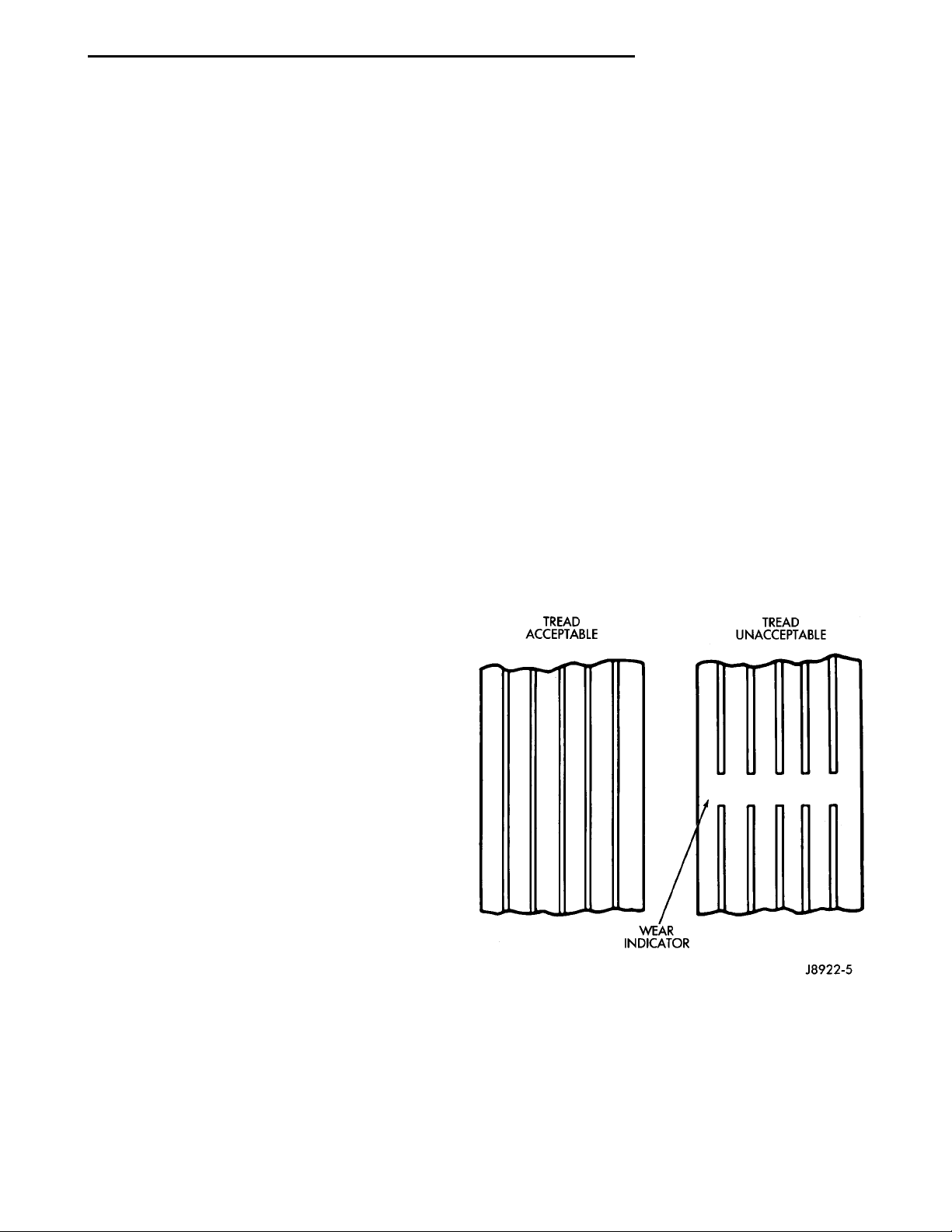
Tread wear indicators are molded into the bottom
of the tread grooves. When tread depth is 1.6 mm
(1/16 in.), the tread wear indicators will appear as a
13 mm (1/2 in.) band.
Tire replacement is necessary when indicators
appear in two or more grooves or if localized balding
occurs (Fig. 4).
REPLACEMENT TIRES
The original equipment tires provide a proper bal-
ance of many characteristics such as:
• Ride
• Noise
• Handling
• Durability
• Tread life
• Traction
• Rolling resistance
• Speed capability
It is recommend that tires equivalent to the original equipment tires be used when replacement is
needed.
Failure to use equivalent replacement tires may
adversely affect the safety and handling of the vehicle.
Fig. 4 Tread Wear Indicators
TIRE WEAR PATTERNS
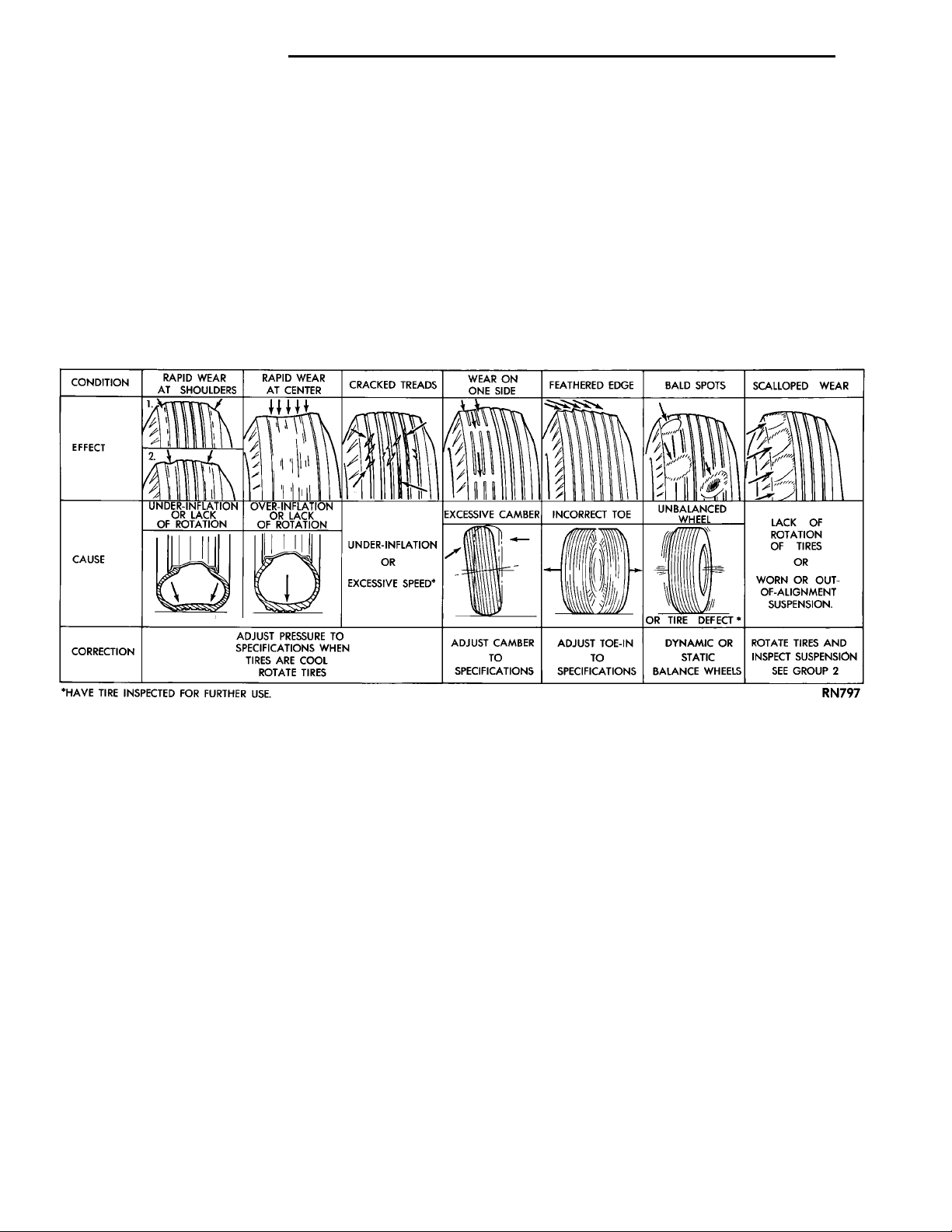
Under inflation results in faster wear on shoulders
of tire. Over inflation causes faster wear at center of
tread.
Excessive camber causes the tire to run at an
angle to the road. One side of tread is worn more
than the other.
Page 4
22 - 4 TIRES AND WHEELS PL
DIAGNOSIS AND TESTING (Continued)
Excessive toe-in or toe-out causes wear on the
tread edges of the tire, from dragging of tire. There is
a feathered effect across the tread (Fig. 5).
TIRE NOISE OR VIBRATION
Radial-ply tires are sensitive to force impulses
caused by improper mounting, vibration, wheel
defects, or possibly tire imbalance.
To find out if tires are causing the noise or vibration, drive the vehicle over a smooth road at varying
speeds. Note the effect of acceleration and decelera-
tion on noise level. Differential and exhaust noises
will change in intensity as speed varies, while tire
noise will usually remain constant.
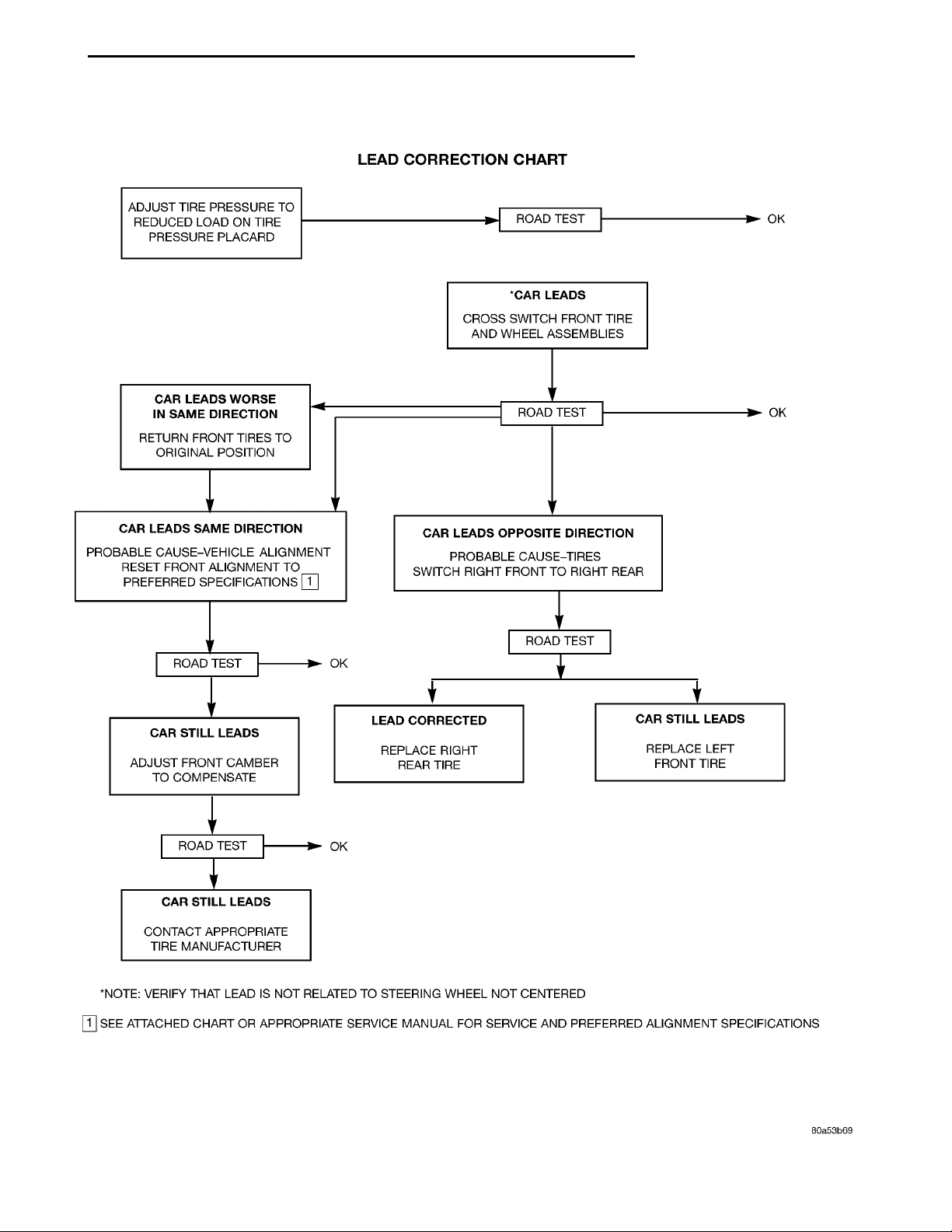
LEAD CORRECTION CHART
Use the following chart to diagnose a vehicle that
has a complaint of a drift or lead condition. The use
of the chart will held to determine if the lead condition is the result of a bad tire or is caused by the
front wheel alignment.
Fig. 5 Tire Wear Patterns
Page 5
LEAD CORRECTION CHARTADJUST TIRE PRESSURE TOREDUCED LOAD ON TIREPRESSURE PLACARDROAD TESTOK*CAR LEADSCROSS SWITCH FRONTTIRE AND WHEEL ASSEM-BLIESCAR LEADS WORSE INSAME DIRECTIONRETURN FRONT TIRES TOORIGINAL POSITIONROAD TESTOKCAR LEADS SAME DIREC-TIONPROBABLE CAUSE-VEHICLEALIGNMENT RESET FRONTALIGNMENT TO PREFERREDSPECIFICATIONSCAR LEADS OPPOSITEDIRECTIONPROBABLE CAUSE-TIRESSWITCH RIGHT FRONT TORIGHT REARROAD TESTROAD TESTOKCAR STILL LEADSADJUST FRONT CAMBER TOCOMPENSATELEAD CORRECTEDREPLACE RIGHT REAR TIRECAR STILL LEADSREPLACE LEFT FRONT TIREROAD TESTOKCAR STILL LEADSCONTACT APPROPRIATETIRE MANUFACTURER*NOTE: VERIFY THAT LEADIS NOT RELATED TO STEER-ING WHEEL NOT CENTEREDSEE ATTACHED CHART ORAPPROPRIATE SERVICEMANUAL FOR SERVICE ANDPREFERRED ALIGNMENTSPECIFICATIONS
PL TIRES AND WHEELS 22 - 5
Page 6
22 - 6 TIRES AND WHEELS PL
SERVICE PROCEDURES
TIRE AND WHEEL ROTATION
NON-DIRECTIONAL TREAD PATTERN TIRES
Tires on the front and rear axles operate at different loads and perform different functions. For these
reasons, they wear at unequal rates, and tend to
develop irregular wear patterns. These effects can be
reduced by timely rotation of tires. The benefits of
rotation are especially worthwhile. Rotation will
increase tread life, help to maintain mud, snow, and
wet traction levels, and contribute to a smooth, quiet
ride.
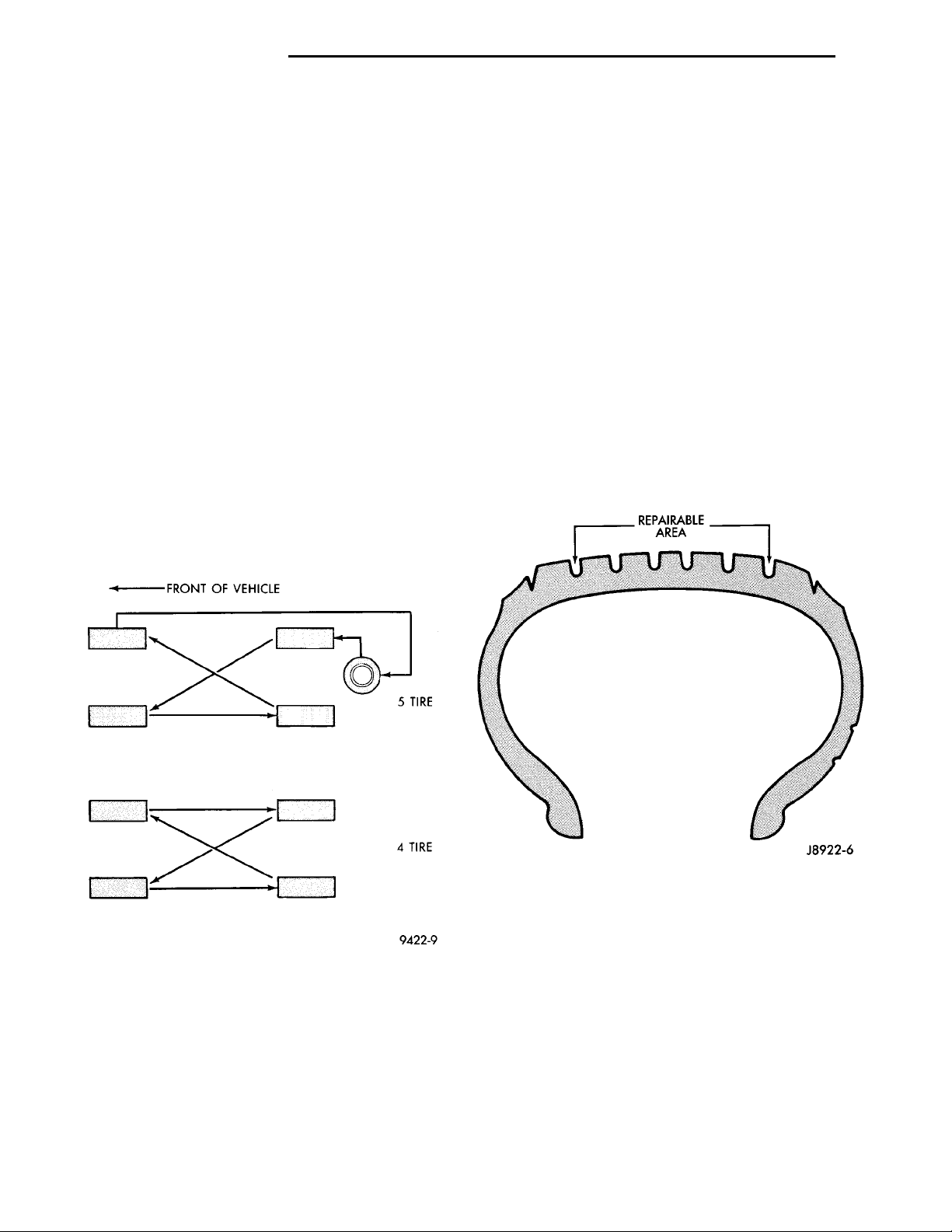
The suggested rotation method is the forward-cross
tire rotation method (Fig. 6). This method takes
advantage of current tire industry practice which
allows rotation of radial-ply tires. Other rotation
methods may be used, but may not have all the benefits of the recommended method.
NOTE: Only the 4 tire rotation method may be used
if the vehicle is equipped with a low mileage or temporary spare tire.
FRONT OF VEHICLE 5 TIRE4 TIRE
When wheels and tires are being installed, extra
care is needed to ensure that this direction of rotation is maintained.
Refer to Owner’s Manual for rotation schedule.
REPAIRING TIRE LEAKS
For proper repairing, a radial tire must be removed
from the wheel. Repairs should only be made if the
defect, or puncture, is in the tread area (Fig. 7). The
tire should be replaced if the puncture is located in
the sidewall.
Deflate tire completely before dismounting tire
from the wheel. Use lubrication such as a mild soap
solution when dismounting or mounting tire. Use
tools free of burrs or sharp edges which could damage the tire or wheel rim.
Before mounting tire on wheel, make sure all rust
is removed from the rim bead and repaint if necessary.
Install wheel on vehicle, and progressively tighten
the 5 wheel nuts to a torque of 135 N·m (100 ft. lbs.).
Fig. 6 Forward-Cross Tire Rotation Method
DIRECTIONAL TREAD PATTERN TIRES
Some vehicles are fitted with special high-performance tires having a directional tread pattern. These
tires are designed to improve traction on wet pavement. To obtain the full benefits of this design, the
tires must be installed so that they rotate in the correct direction. This is indicated by arrows on the tire
sidewalls.
Fig. 7 Tire Repair Area
TIRE AND WHEEL MATCH MOUNTING
Wheels and tires are match mounted at the factory.
This means that the high spot of the tire is matched
to the low spot on the wheel rim. This technique is
used to reduce run-out in the wheel/tire assembly.
The high spot on the tire is marked with a paint
mark or a bright colored adhesive label on the outboard sidewall. The low spot on the rim is identified
with a label on the outside of the rim and a dot or
line on the inside of the rim. If the outside label has
been removed the tire will have to be removed to
locate the dot or line on the inside of the rim.
Before dismounting a tire from its wheel, a reference mark should be placed on the tire at the valve
Page 7
2ND HIGH SPOT ONTIRE1ST HIGH SPOTON TIRE
PL TIRES AND WHEELS 22 - 7
SERVICE PROCEDURES (Continued)
stem location. This reference will ensure that it is
remounted in the original position on the wheel.
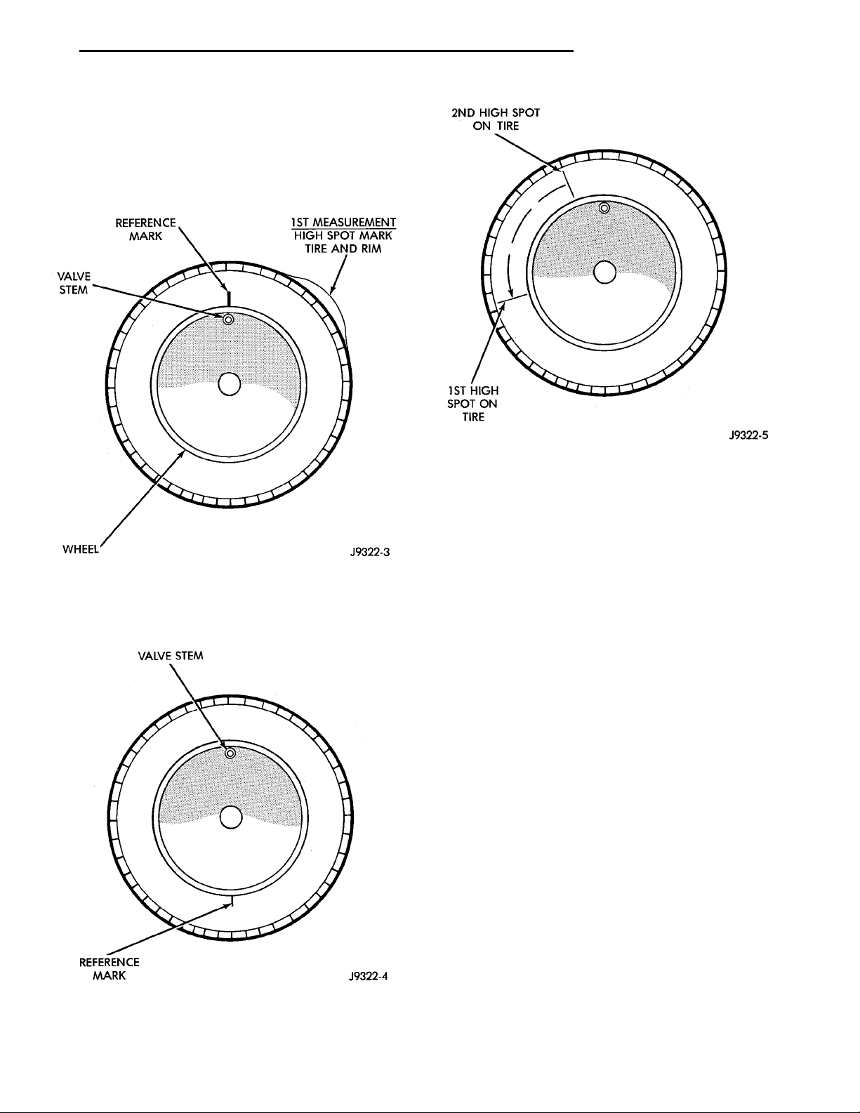
(1) Measure the total indicator runout on the center of the tire tread rib. Record the indicator reading.
Mark the tire to indicate the high spot. Place a mark
on the tire at the valve stem location (Fig. 8).
VALVESTEMREFERENCEMARK
Fig. 8 First Measurement On Tire
(2) Break down the tire and remount it 180
degrees on the rim (Fig. 9).
Fig. 9 Remount Tire 180 Degrees
Fig. 10 Remount Tire 90 Degrees In Direction of
Arrow
(3) Measure the total indicator runout again. Mark
the tire to indicate the high spot.
(4) If runout is still excessive, the following proce-
dures must be done.
• If the high spot is within 102 mm (4.0 in.) of the
first spot and is still excessive, replace the tire.
• If the high spot is within 102 mm (4.0 in.) of the
first spot on the wheel, the wheel may be out of specifications. Refer to Wheel and Tire Runout.
• If the high spot is NOT within 102 mm (4.0 in.)
of either high spot, draw an arrow on the tread from
second high spot to first. Break down the tire and
remount it 90 degrees on rim in that direction (Fig.
10). This procedure will normally reduce the runout
to an acceptable amount.
CLEANING AND INSPECTION
CLEANING OF TIRES
Remove protective coating on tires before delivery
of vehicle. The coating could cause deterioration of
tires.
Remove protective coating by:
• Applying warm water
• Letting it soak one minute
• Scrubbing the coating away with a soft bristle
brush.
• Steam cleaning may also be used for cleaning.
• DO NOT use gasoline or wire brush for cleaning.
• DO NOT use mineral oil or an oil-based solvent.
Page 8

22 - 8 TIRES AND WHEELS PL
SPECIFICATIONS
TIRE SPECIFICATIONS
The following guide should help you understand the tire designations:
P Passenger car tire (or “T” for temporary-use tire).
185 Nominal width of tire in millimeters.
70 Tire height-to-width ratio.
R Radial-ply tire (or “D” for bias-ply tire).
14 Nominal rim diameter in inches.
Do not install smaller than minimum size tires shown on the tire inflation placard on the vehicle.
Page 9
TIREWELLSAFETY HUMPSFLANGE
PL TIRES AND WHEELS 22 - 9
WHEELS
INDEX
page page
DESCRIPTION AND OPERATION
WHEEL COVER (LOCK-ON) ................ 9
WHEEL INFORMATION ................... 9
DIAGNOSIS AND TESTING
TIRE AND WHEEL RUNOUT ............... 9
WHEEL INSPECTION ..................... 9
SERVICE PROCEDURES
TIRE AND WHEEL BALANCE .............. 10
DESCRIPTION AND OPERATION
WHEEL INFORMATION
Original equipment wheels are designed for proper
operation at all loads up to the specified maximum
vehicle capacity.
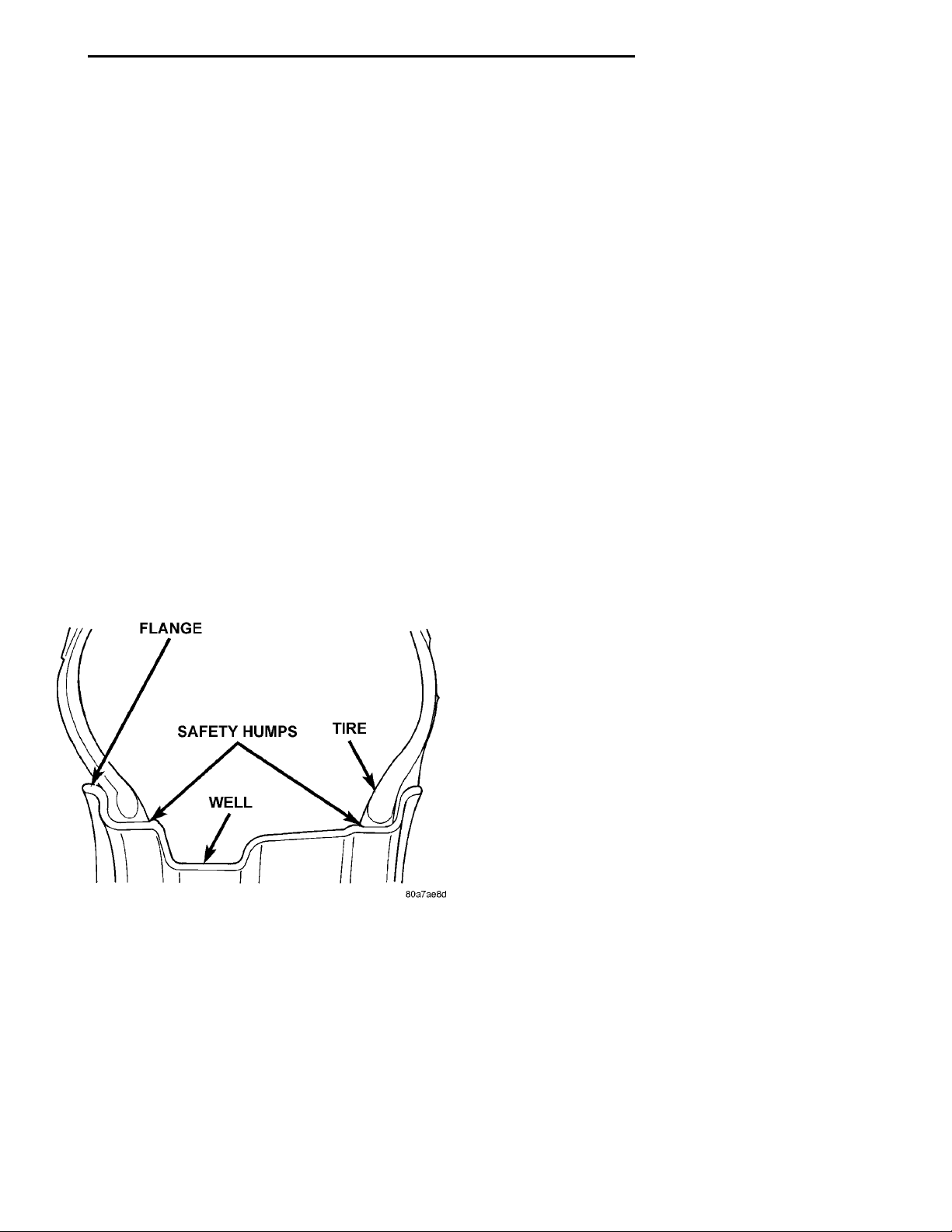
All models use steel or cast aluminum drop center
wheels. Every wheel has raised sections between the
rim flanges and rim drop well called safety humps
(Fig. 1).
REMOVAL AND INSTALLATION
WHEEL AND TIRE ...................... 12
WHEEL COVER (LOCK-ON) ............... 11
WHEEL COVER RETAINING NUT .......... 13
SPECIFICATIONS
WHEEL SPECIFICATIONS ................ 14
The wheel studs and nuts are designed for specific
wheel applications and must be replaced with equivalent parts. Do not use replacement parts of lesser
quality or of a substitute design. All aluminum
wheels use wheel nuts with an enlarged nose. This
enlarged nose is necessary to ensure proper retention
of the wheels.
Vehicles that are equipped with bolt-on wheel covers use large nose wheel nuts. The wheel nuts used
on a vehicle equipped with bolt-on wheel covers are
externally threaded so that the wheel covers can be
attached to the wheel nuts.
Before installing a wheel, remove any buildup of
corrosion on the wheel mounting surface.
WARNING: INSTALLING WHEELS WITHOUT GOOD
METAL-TO-METAL CONTACT COULD CAUSE LOOSENING OF WHEEL LUG NUTS. THIS COULD
ADVERSELY AFFECT THE SAFETY AND HANDLING
OF YOUR VEHICLE.
Fig. 1 Safety Rim
Initial inflation of the tires forces the bead over
these raised sections. In case of air loss the raised
sections help hold the tire in position on the wheel
until the vehicle can be brought to a safe stop.
Cast aluminum wheels require special balance
weights to fit on the thicker flange of the rim and
special wheel clamps for the alignment equipment.
WHEEL COVER (LOCK-ON)
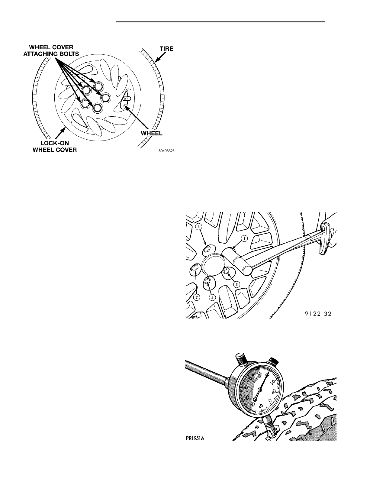
For the 1997 model year, a lock-on type wheel
cover (Fig. 2) is used on certain models of this vehicle.
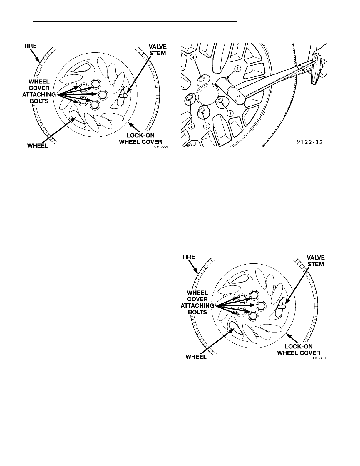
The wheel cover is locked to the wheel using the 5
nuts located in the wheel cover (Fig. 2). The nuts in
the wheel cover thread onto a special externally
threaded wheel nut (Fig. 2). This is the method used
to retain the wheel cover to the wheel.
The wheel cover retaining nut (Fig. 2) is retained
in the wheel cover and will stay on the wheel cover
when un-threaded from the wheel nut. If required,
the retaining nut for the lock-on wheel cover can be
removed from the wheel cover and replaced as a separate part of the lock-on wheel cover.
Page 10
WHEEL COVER ATTACHINGBOLTSTIREWHEELLOCK-ON WHEEL COVER
22 - 10 TIRES AND WHEELS PL
DESCRIPTION AND OPERATION (Continued)
Radial run out is the difference between the high
and low points on the outer edge of the tire or wheel.
Lateral run out is the total side–to–side wobble of
the tire or wheel.
Radial run out of more than 1.5 mm (.060 inch)
measured at the center line of the tread may cause
the vehicle to shake.
Lateral run out of more than 2.0 mm (.080 inch)
measured at the side of the tire as close to the tread
as possible may cause the vehicle to shake.
Sometimes radial run out can be reduced by relocating the wheel and tire on the wheel studs (See
Method 1). If this does not reduce run out to an
acceptable level, the tire can be rotated on the wheel.
(See Method 2).
Fig. 2 Wheel Nut And Wheel Cover Retaining Nut
The lock-on wheel cover can not be removed from
the wheel until all 5 of wheel cover retaining nuts
are un-threaded from the wheel nuts. Then the
lock-on wheel cover can be removed by hand from the
wheel.
DIAGNOSIS AND TESTING
WHEEL INSPECTION
WARNING: FAILURE TO USE EQUIVALENT
REPLACEMENT WHEELS MAY ADVERSELY AFFECT
THE SAFETY AND HANDLING OF THE VEHICLE.
WARNING: REPLACEMENT WITH USED WHEELS
IS NOT RECOMMENDED. THE SERVICE HISTORY
OF THE RIM MAY HAVE INCLUDED SEVERE TREATMENT OR VERY HIGH MILEAGE. THE RIM COULD
FAIL WITHOUT WARNING.
Wheels must be replaced if they:
• Have excessive run out
• Are bent or dented
• Leak air from any area or surface of the rim
• Have damaged wheel lug/ nut holes
Wheel repairs employing hammering, heating,
welding or repairing leaks are not allowed.
Original equipment replacement wheels should be
used. When obtaining replacement wheels, they
should be equivalent in load carrying capacity. The
physical dimensions (diameter, width, offset, pilot
hole and bolt circle) of the wheel should be the same
as the original wheel.
METHOD 1 (RELOCATE WHEEL ON HUB)
Check accuracy of the wheel mounting surface;
adjust wheel bearings.
Drive vehicle a short distance to eliminate tire flat
spotting from a parked position.
Verify all wheel nuts are tightened and properly
torqued in the correct sequence (Fig. 3).
Fig. 3 Tightening Wheel Nuts
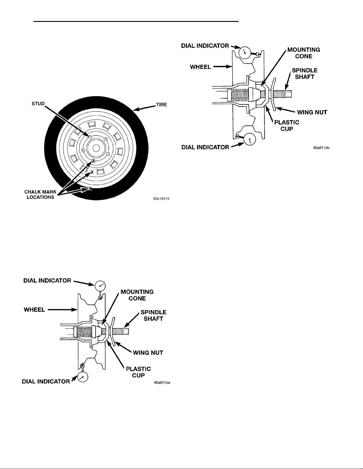
Use run out gauge D-128-TR to determine run out
(Fig. 4).
TIRE AND WHEEL RUNOUT
NOTE: Runout should always be measured off the
vehicle and on a suitable balance machine.
Fig. 4 Run Out Gauge
Page 11
MOUNTING CONESPINDLE SHAFTWING NUTPLASTIC CUPDIAL INDICATORWHEELDIAL INDICATOR
PL TIRES AND WHEELS 22 - 11
MOUNTING CONESPINDLE SHAFTWING NUTPLASTIC CUPDIAL INDICATORWHEELDIAL INDICATOR
STUDTIRECHALK MARK LOCATIONS
DIAGNOSIS AND TESTING (Continued)
Relocate the wheel on the mounting studs, two
studs over from the original position.
Retighten wheel nuts until all are properly
torqued. This will prevent brake distortion.
Check radial run out. If still excessive, mark tire
sidewall, wheel, and stud at point of maximum run
out (Fig. 5) and proceed to Method 2.
Fig. 7 Checking Wheel Lateral Run Out
run out. If this does not reduce the run out to an
acceptable level, replace the wheel and/or the tire.
Fig. 5 Chalk Marking On Wheel, Tire And Stud
METHOD 2 (RELOCATE TIRE ON WHEEL)
Rotating tire on wheel is particularly effective
when there is run out in both tire and wheel.
Remove tire from wheel and remount wheel on hub
in former position.
Check the radial run out of the wheel (Fig. 6). The
radial runout should be no more than 0.762 mm
(0.030 inch).
Fig. 6 Checking Wheel Radial Run Out
Check the lateral run out of the wheel (Fig. 7). The
lateral run out should be no more than 0.762 mm
(0.030 inch).
If the point of greatest wheel radial run out is near
the original chalk mark, remount the tire on the rim
180 degrees from its original position. Recheck the
SERVICE PROCEDURES
TIRE AND WHEEL BALANCE
Balancing need is indicated by vibration of seats,
floor pan, or steering wheel. The vibration will be
noticed mostly when driving over 90 km/h (55 mph)
on a smooth road.
It is recommended that a two plane dynamic balancer be used when a wheel and tire assembly
require balancing. Static should be used only when a
two plane balancer is not available.
Off-vehicle tire and wheel balancing is recommended to be used on this vehicle.
NOTE: If on vehicle equipment is being used to balance the tire /wheel assemblies, remove the opposite tire/wheel from the vehicle.
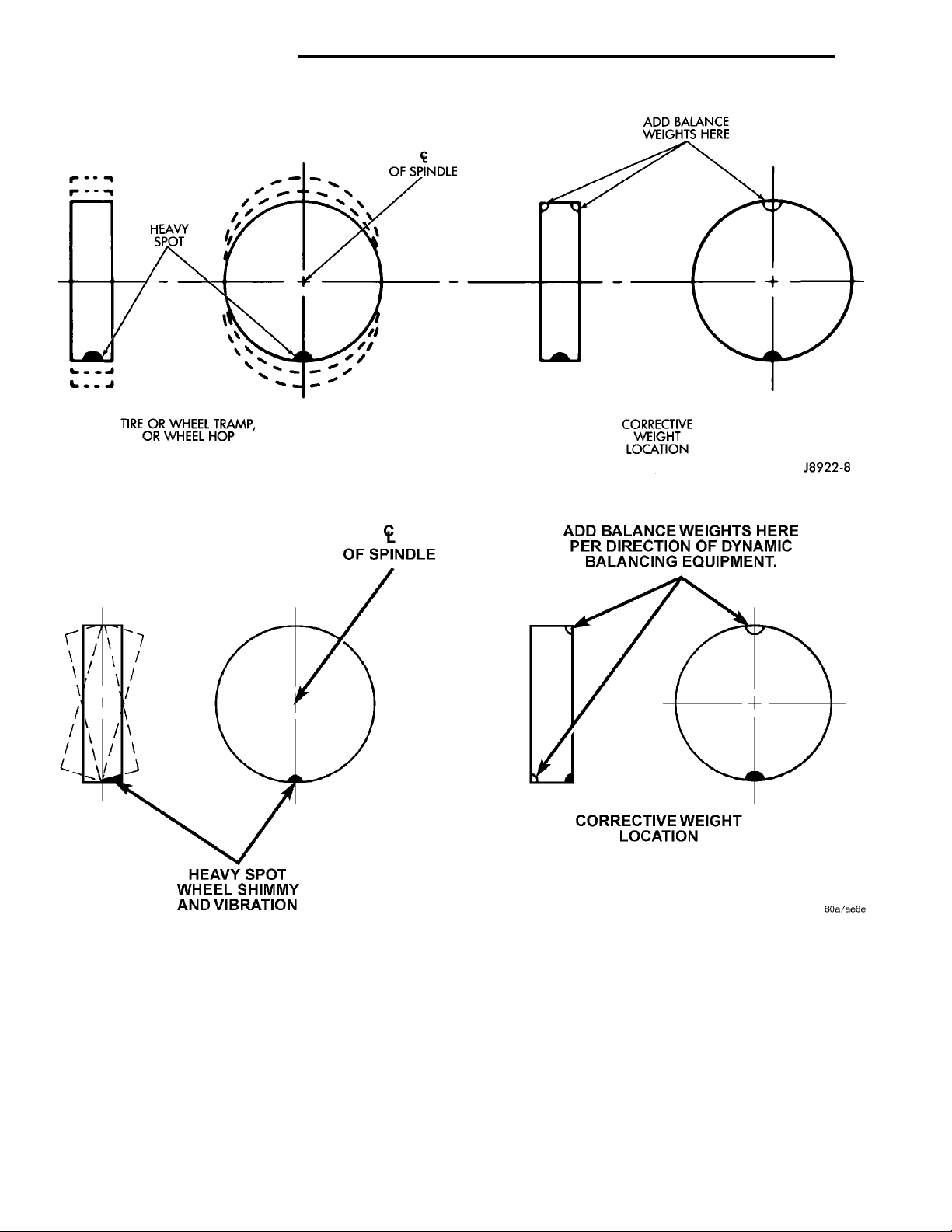
For static balancing, find the location of heavy spot
on tire/wheel causing the imbalance. Counter balance
wheel directly opposite the heavy spot. Determine
weight required to counterbalance the area of imbalance. Place half of this weight on the inner rim
flange and the other half on the outer rim flange
(Fig. 8).
For dynamic balancing, the balancing equipment is
designed to indicate the location and amount of
weight to be applied to both the inner and outer rim
flanges (Fig. 9)
Page 12
HEAVYSPOT OF SPINDLE ADD BALANCEWEIGHTS HERECORRECTIVE WEIGHTLOCATIONTIRE OR WHEEL TRAMP, ORWHEEL HOP
OF SPINDLEADD BALANCE WEIGHTSHERE PER DIRECTION OFDYNAMIC BALANCINGEQUIPMENT.CORRECTIVE WEIGHTLOCATIONHEAVY SPOT WHEELSHIMMY AND VIBRATION
22 - 12 TIRES AND WHEELS PL
Fig. 8 Static Unbalance & Balance
Fig. 9 Dynamic Unbalance & Balance
REMOVAL AND INSTALLATION
WHEEL COVER (LOCK-ON)
REMOVE
NOTE: When unthreading the wheel cover retaining
nuts (Fig. 10) from the wheel nuts it is recommended that a hand wrench be used and not an
impact wrench. Use of an impact wrench could
result in damage to the lock-on wheel cover retaining nuts.
(1) Un-thread the 5 nuts (Fig. 10) attaching the
wheel cover to the wheel nuts.
(2) Grasp the wheel cover and pull straight outward from the wheel. This will remove the wheel
cover from the wheel.
Page 13
TIREVALVE STEMLOCK-ON WHEEL COVERWHEELWHEEL COVER ATTACHINGBOLTS
TIREVALVE STEMLOCK-ON WHEEL COVERWHEELWHEEL COVER ATTACHINGBOLTS
PL TIRES AND WHEELS 22 - 13
REMOVAL AND INSTALLATION (Continued)
Fig. 10 Wheel Cover Attaching Nuts
INSTALL
(1) Align the valve notch in the wheel cover with
the valve stem on the wheel (Fig. 10). Align the
wheel cover retaining nuts with the externally
threaded wheel nuts.
(2) By hand, start to thread all 5 of the wheel
cover retaining nuts onto the externally threaded
wheel nuts.
NOTE: When tightening the wheel cover retaining
nuts it is recommended that a hand wrench be used
and not an impact wrench. Use of an impact wrench
could result in damage to the lock-on wheel cover
retaining nuts.
(3) Tighten each of the wheel cover retaining nuts.
If the retaining nut “jumps” a thread (slips), which is
an override feature of the retaining nut, retighten
the retaining nut to a point just prior to this occurring. To avoid rattling of the wheel cover be sure all
five retaining nuts are correctly tightened.
WHEEL AND TIRE
Fig. 11 Tightening Wheel Nuts
cover is removed by un-threading the wheel cover
retaining nuts and pulling it off the wheel by hand.
NOTE: When unthreading the wheel cover retaining
nuts (Fig. 12) from the wheel nuts it is recommended that a hand wrench be used and not an
impact wrench. Use of an impact wrench could
result in damage to the lock-on wheel cover retaining nuts.
(1) Un-thread the 5 nuts (Fig. 12) attaching the
wheel cover to the wheel nuts.
CAST ALUMINUM WHEEL
To install the wheel, first position it properly on
the mounting surface using the hub pilot as a guide.
All wheel nuts should be lightly tightened before progressively tightening them in the proper sequence
(Fig. 11). Then tighten wheel nuts in the proper
sequence to a torque of 135 N·m (100 ft. lbs.). Never
use oil or grease on studs or nuts.
STEEL WHEEL
REMOVE
CAUTION: When removing the wheel cover, do not
attempt pry the wheel cover off the wheel. This can
result in damage to the wheel cover. The wheel
Fig. 12 Wheel Cover Locking Nuts
(2) Grasp the wheel cover and pull straight outward. This will remove the wheel cover from the
wheel.
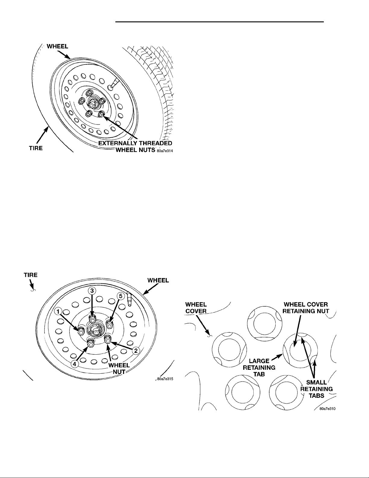
(3) Remove the wheel nuts (Fig. 13) from the
studs.
(4) Remove the wheel and tire from the hub.
Page 14
WHEELEXTERNALLY THREADEDWHEEL NUTSTIRE
TIREWHEELWHEEL NUT
WHEEL COVERWHEEL COVER RETAININGNUTSMALL RETAINING TABSLARGE RETAINING TAB
22 - 14 TIRES AND WHEELS PL
REMOVAL AND INSTALLATION (Continued)
NOTE: When tightening the wheel cover retaining
nuts it is recommended that a hand wrench be used
and not an impact wrench. Use of an impact wrench
could result in damage to the lock-on wheel cover
retaining nuts.
(5) Tighten each of the wheel cover retaining nuts.
If the retaining nut “jumps” a thread (slips), which is
an override feature of the retaining nut, retighten
the retaining nut to a point just prior to this occurring. To avoid rattling of the wheel cover be sure all
five retaining nuts are correctly tightened.
WHEEL COVER RETAINING NUT
If a retaining nut for the lock-on wheel is damaged,
it can be replaced as a separate part of the wheel
Fig. 13 Wheel Nuts
INSTALL
(1) To install the wheel, first position it properly
on the studs and hub mounting surface using the
hub pilot as a guide. Install and lightly tighten the
wheel nuts in the proper sequence (Fig. 14).
CAUTION: When installing the wheel/tire never use
oil or grease on studs or nuts.
(2) Progressively tighten the 5 wheel nuts in the
proper sequence (Fig. 14) until tightened to half of
the specified torque. Then tighten the wheel nuts in
the proper sequence to a torque of 135 N·m (100 ft.
lbs.).
cover. Use the following procedure for replacing a
wheel cover retaining nut.
REMOVE
(1) If required, remove the wheel cover from the
wheel. Refer to Wheel Cover Lock-On in the Removal
And Installation Section in this group of the service
manual for the procedure.
NOTE: The retaining nut flange can not be forced
past the large retaining tab. When removing retaining nut from wheel cover, the flange on the retaining nut must be forced past the 2 small retaining
tabs on wheel cover.
(2) From the back side of the wheel cover, push
outward and tilt the retaining nut sideways forcing
the flange on the retaining nut past the 2 small
retaining tabs in the retaining nut hole of the wheel
cover (Fig. 15).
Fig. 14 Wheel Nut Tightening Sequence
(3) Align the valve notch in the wheel cover with
the valve stem on the wheel (Fig. 12). Align the
wheel cover retaining nuts with the externally
threaded wheel nuts.
(4) By hand, start to thread all 5 of the wheel
cover retaining nuts onto the externally threaded
wheel nuts.
Fig. 15 Wheel Cover Retaining Nut Retention
(3) When flange on retaining nut is past the 2
retaining tabs on the wheel cover, remove retaining
Page 15

PL TIRES AND WHEELS 22 - 15
REMOVAL AND INSTALLATION (Continued)
nut from wheel cover by pushing or pulling from hole
in wheel cover.
INSTALL
(1) Install retaining nut in hole of wheel cover
with retaining nut flange positioned under the large
retaining flange (Fig. 15).
(2) Push on hex of retaining nut forcing the retaining nut flange past the 2 small retaining tabs in
wheel cover.
SPECIFICATIONS
WHEEL SPECIFICATIONS
Wheel:
Mounting Stud Size ..............M12x1.5mm
Mounting Stud Lug Nut Hex Size .........19mm
Mounting Lug Nut Tightening
Torque (4 and 5 Stud Wheels) .....109–150 N·m
(80 to 110 ft. lbs.)
Page 16

 Loading...