

Page 1
PL TRANSAXLE 21 - 1
TRANSAXLE
CONTENTS
page page
DESCRIPTION AND OPERATION
BRAKE TRANSMISSION SHIFT INTERLOCK
(BTSI) SYSTEM ........................ 1
DIAGNOSIS AND TESTING
BRAKE TRANSMISSION SHIFT INTERLOCK
(BTSI) SYSTEM ........................ 1
DESCRIPTION AND OPERATION
BRAKE TRANSMISSION SHIFT INTERLOCK (BTSI) SYSTEM
The Brake Transmission Shift Interlock (BTSI)
System, is a cable and solenoid operated system. It
interconnects the automatic transmission floor
mounted shifter to the steering column ignition
switch. The BTSI system locks the shifter into the
PARK position. The BTSI system is engaged whenever the ignition switch is in the LOCK or ACCESSORY position.
An additional electrically activated feature will
prevent shifting out of the PARK position unless the
brake pedal is depressed at least one-half an inch. A
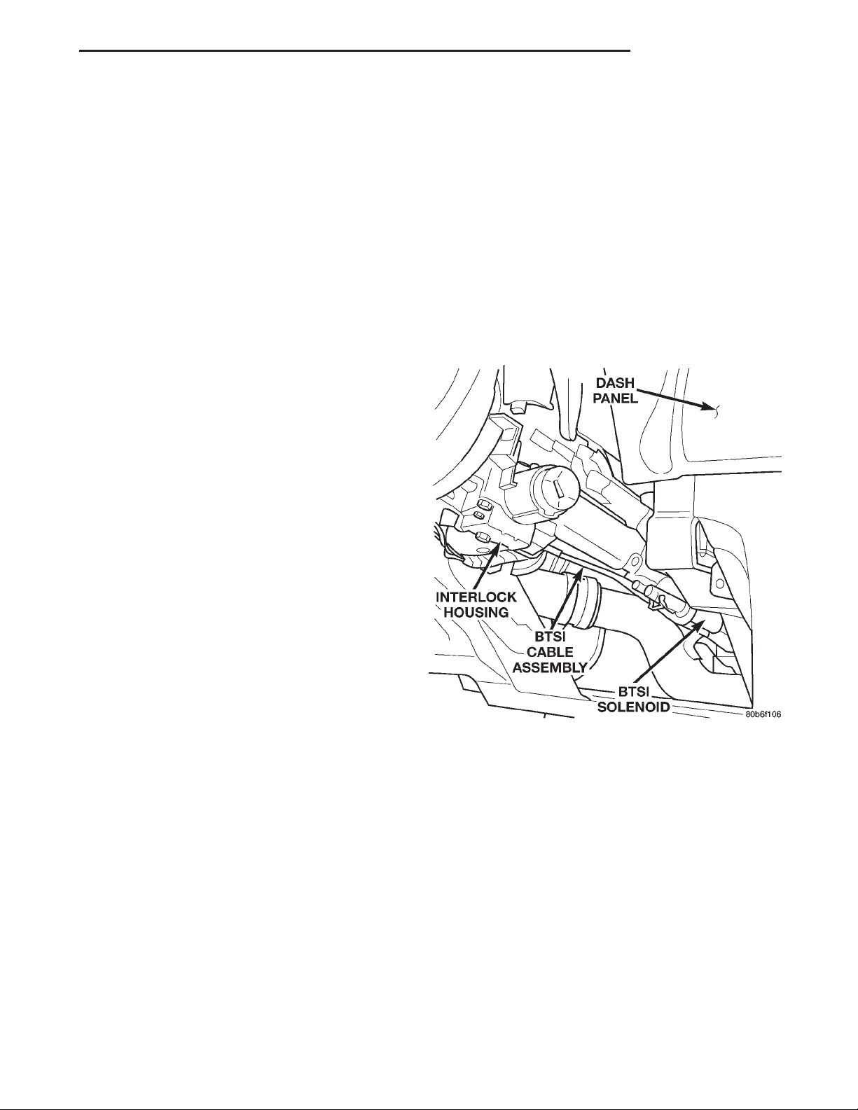
solenoid integrated with the BTSI cable assembly
(Fig. 1) is energized when the ignition switch is in
the RUN position. When the key is in the RUN position and the brake pedal is depressed, the shifter is
unlocked and will move into any position. The BTSI
system also prevents the ignition switch from being
turned to the LOCK or ACCESSORY position, unless
the shifter is fully locked into the PARK position.
REMOVAL AND INSTALLATION
BRAKE TRANSMISSION SHIFT INTERLOCK
(BTSI) CABLE ASSEMBLY ................ 2
ADJUSTMENTS
BRAKE TRANSMISSION SHIFT INTERLOCK
(BTSI) SYSTEM ADJUSTMENT ............ 4
Fig. 1 BTSI Cable Assembly
DIAGNOSIS AND TESTING
BRAKE TRANSMISSION SHIFT INTERLOCK (BTSI) SYSTEM
If the ignition switch cannot be turned to the
LOCK position, with the shifter in PARK and the
brake pedal depressed, an adjustment of the Brake
Transmission Shift Interlock (BTSI) System may be
required. To adjust the Brake Transmission Shift
Interlock (BTSI) System, follow the procedure in the
Adjustment section of this group.
Page 2
21 - 2 TRANSAXLE PL
REMOVAL AND INSTALLATION
BRAKE TRANSMISSION SHIFT INTERLOCK (BTSI) CABLE ASSEMBLY
REMOVAL
(1) Disconnect and isolate, the battery negative (-)
cable from the vehicle battery.
(2) Remove console assembly. Refer to Group 23,
Body.
(3) Remove the gearshift knob set screw and knob.
(4) Remove the screws retaining the gearshift indi-
cator bezel and remove bezel and indicator lamp.
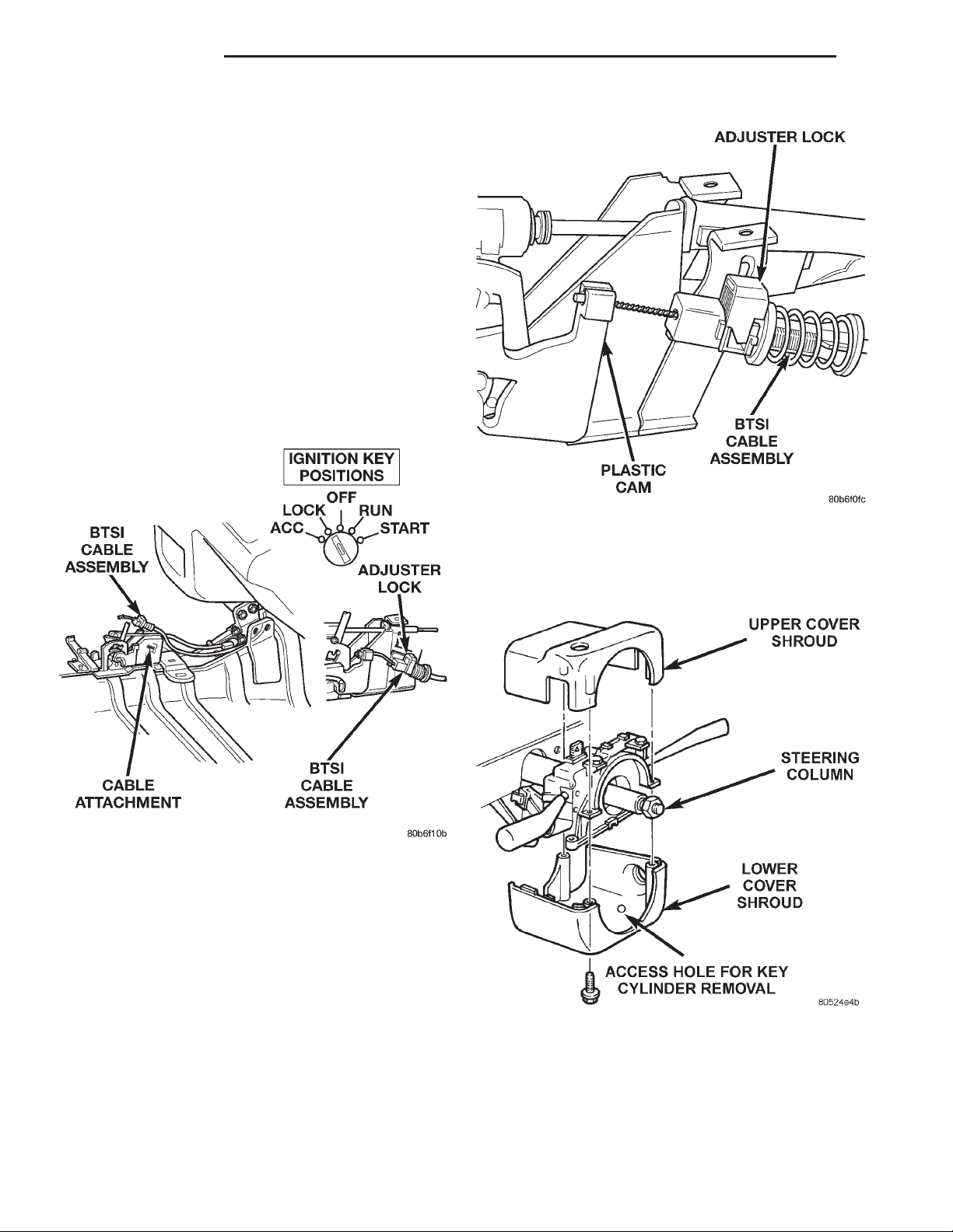
(5) Pry up the adjuster lock on the BTSI cable
assembly. Unsnap the BTSI cable assembly end fitting from the groove in the gearshift mechanism (Fig.
2).
Fig. 2 Brake Transmission Shift Interlock (BTSI)
Cable Assembly
(6) Remove the cable core end from the plastic cam
of the shifter mechanism (Fig. 3) and pull the BTSI
cable out of the gear shift mechanism.
(7) Remove the steering column cover. Refer to
Group 8E, Instrument Panels and Systems for
Removal and Installation procedures.
(8) Remove the steering column cover liner. Refer
to Group 8E, Instrument Panel and Systems for
Removal and Installation Procedures.
Fig. 3 Gearshift Mechanism Plastic Cam
(9) Remove the three lower–to–upper shroud
attaching screws through the bottom of the lower
shroud and remove the lower shroud (Fig. 4).
Fig. 4 Upper/Lower Shroud
(10) Turn the ignition to the RUN position.
Page 3
PL TRANSAXLE 21 - 3
REMOVAL AND INSTALLATION (Continued)
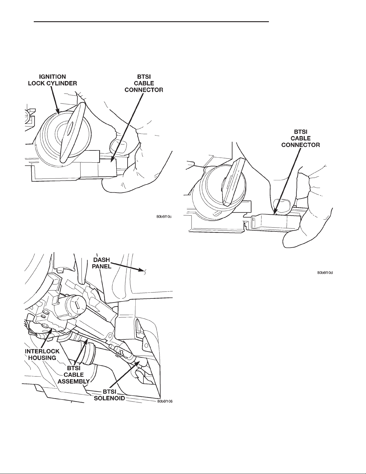
(11) Grasp the BTSI cable assembly clip and connector. Remove the connector from the interlock
housing (Fig. 5).
INSTALLATION
CAUTION: When installing BTSI cable assembly,
care must be taken not to bend exposed cable wire
and slug at shifter end of cable.
(1) Route BTSI cable assembly into lower dash
panel.
(2) Install the BTSI cable assembly connector into
the interlock housing at the steering column (Fig. 7).
Verify the cable snaps into the housing.
Fig. 5 BTSI Cable Assembly Connector
(12) Disconnect the BTSI solenoid electrical con-
nector (Fig. 6).
Fig. 6 BTSI Solenoid
(13) Unclip the BTSI cable assembly from the
retaining clip located within the wiring harness.
(14) Remove BTSI cable assembly from the dash
panel.
Fig. 7 BTSI Cable at Interlock Housing
(3) Install BTSI cable assembly into routing clip
located within the wiring harness.
(4) Route BTSI cable assembly to the console.
(5) Install the cable core end to the plastic cam of
the shifter mechanism. Snap the BTSI cable assembly end fitting into the groove in the gearshift mechanism.
(6) Adjust the Brake Transmission Shift Interlock
(BTSI) System. See Brake Transmission Shift Interlock (BTSI) System Adjustment, in this section.
(7) Check operation of the Brake Transmission
Shift Interlock (BTSI) System, as described in the
beginning of this section.
(8) Install console assembly. Refer to Group 23,
Body.
(9) Install screws retaining the gearshift indicator
bezel and install bezel and indicator lamp.
(10) Install the gearshift knob set screw and knob.
(11) Install two screws at the upper area of the
column liner and lower left corner.
Page 4
21 - 4 TRANSAXLE PL
REMOVAL AND INSTALLATION (Continued)
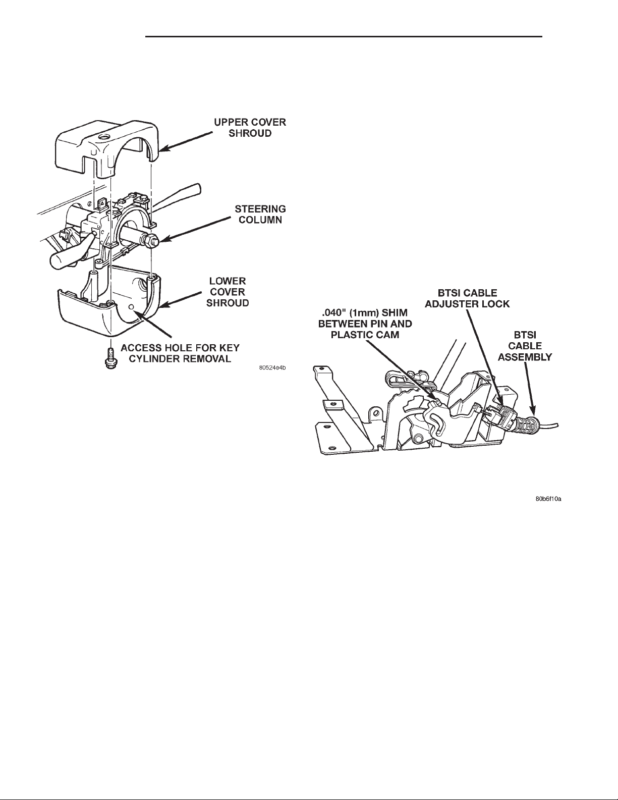
(12) Position the lower shroud in place. Install the
three lower–to–upper shroud attaching screws
through the bottom of the lower shroud (Fig. 8).
(6) Place shifter in PARK.
(7) Turn ignition switch to the LOCK or ACCESSORY position. If cable has lost its adjustment, manually position cable to get key into LOCK or
ACCESSORY position. Grasp slug on interlock cable
with needle nose pliers and pull back on cable. This
will allow the ignition switch to be turned to the
LOCK or ACCESSORY position.
(8) Check that the interlock cable slug is completely seated into the shifter interlock lever.
(9) Check that the ignition switch is still in the
LOCK or ACCESSORY position.
(10) Pry up the adjuster lock on the BTSI cable
(Fig. 9).
Fig. 8 Upper/Lower Shroud
(13) Reconnect the battery negative (-) cable to the
vehicle battery.
ADJUSTMENTS
BRAKE TRANSMISSION SHIFT INTERLOCK (BTSI) SYSTEM ADJUSTMENT
If ignition switch cannot be turned to the LOCK
position, with shifter in PARK, an adjustment of the
Interlock System may be required. To adjust the
Brake Transmission Shift Interlock (BTSI) System,
follow procedure listed below.
(1) Disconnect and isolate, the battery negative (-)
cable from the vehicle battery.
(2) Remove console assembly. Refer to Group 23,
Body.
(3) Remove the gearshift knob set screw and knob.
(4) Remove the screws retaining the gearshift indicator bezel and remove bezel and indicator lamp.
(5) Reinstall the gearshift knob.
Fig. 9 BTSI Cable Adjuster Lock
(11) Place a 1mm (0.040) shim between the larger
diameter portion of the shifter gate pin and the plastic cam (Fig. 9).
(12) The spring on the BTSI cable should automatically compensate for the slack in the adjuster.
(13) Snap down the interlock adjuster lock onto
the cable and remove the shim.
(14) After adjusting the BTSI system, check operation of the Brake Transmission Shift Interlock
(BTSI) System, as described in the beginning of this
section.
 Loading...