

Page 1

PL SUSPENSION 2 - 1
SUSPENSION
CONTENTS
page page
FRONT SUSPENSION ..................... 9
REAR SUSPENSION ..................... 36
WHEEL ALIGNMENT
INDEX
page page
DESCRIPTION AND OPERATION
WHEEL ALIGNMENT GENERAL INFORMATION
....................................... 1
DIAGNOSIS AND TESTING
PRE-ALIGNMENT VEHICLE INSPECTION ..... 4
SUSPENSION AND STEERING DIAGNOSIS . . . 3
DESCRIPTION AND OPERATION
WHEEL ALIGNMENT GENERAL INFORMATION
Proper vehicle wheel alignment is the proper
adjustment of all interrelated front and rear suspension angles (Fig. 1). These angles are what affects
the handling and steering of the vehicle when it is in
motion.
The method of checking a vehicle’s front and rear
wheel alignment will vary depending on the type and
manufacturer of the equipment being used. Instructions furnished by the manufacturer of the equipment being used should always be followed to ensure
accuracy of the alignment, except alignment specifi-
WHEEL ALIGNMENT ..................... 1
SERVICE PROCEDURES
WHEEL ALIGNMENT CHECK AND
ADJUSTMENT PROCEDURE ............. 5
SPECIFICATIONS
VEHICLE ALIGNMENT SPECIFICATIONS AT
CURB HEIGHT ........................ 8
cations recommended by Chrysler Corporation
MUST ALWAYS be used.
CAUTION: Do not attempt to modify any suspension or steering components by heating or bending
of the component.
Wheel alignment adjustments should be made in
the following sequence, to ensure that an accurate
alignment is performed.
(1) Rear Wheel Toe Adjustment within specifications for both total toe and thrust angle.
(2) Front Wheel Toe Adjustment within specifications for total toe.
Page 2
2 - 2 SUSPENSION PL
DESCRIPTION AND OPERATION (Continued)
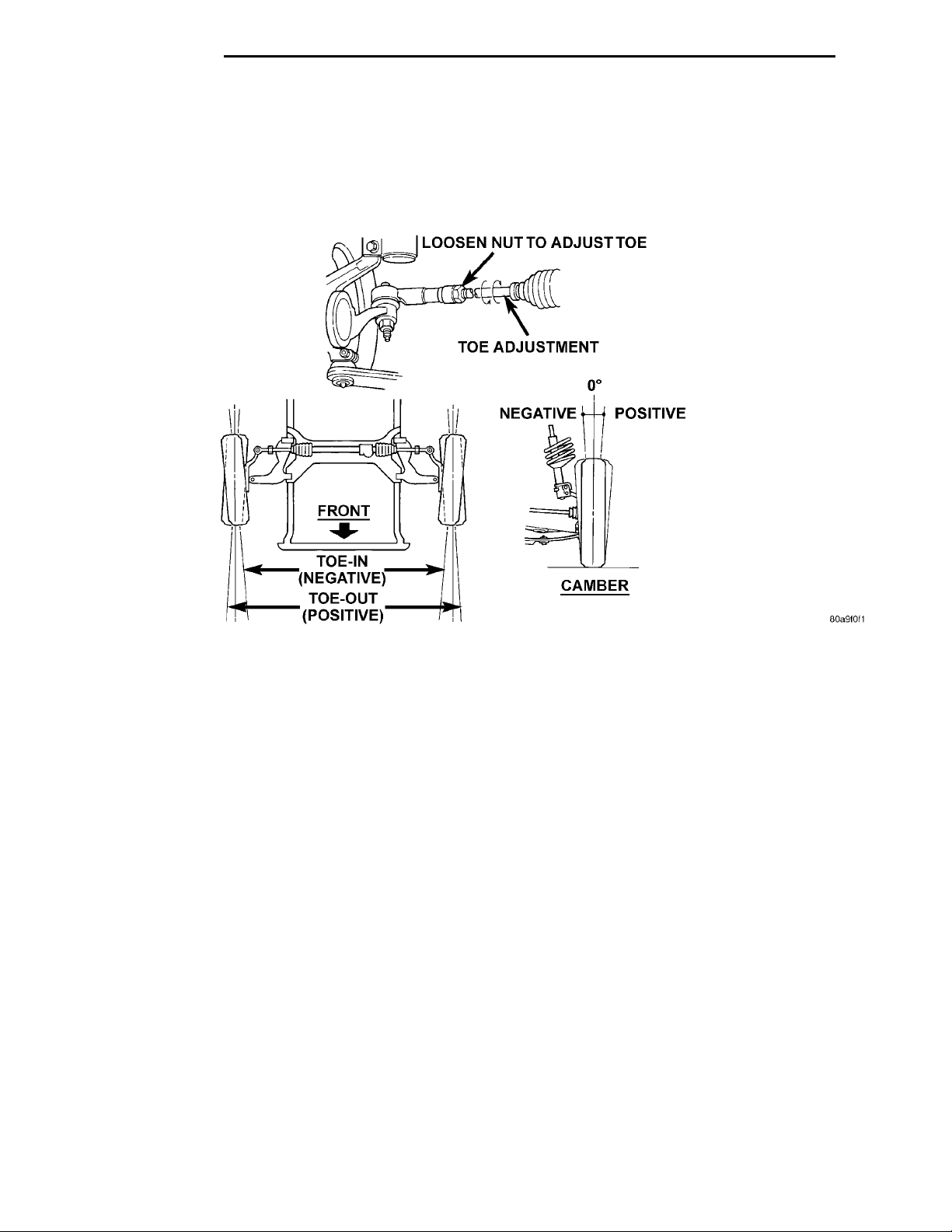
(3) Toe is measured in degrees or inches and is
the distance that the front edges of the tires are
closer (or farther apart) than the rear edges (Fig. 1).
See Front Wheel Drive Specifications for correct front
and rear wheel Toe specifications.
(4) Thrust Angle is defined as the average of the
Toe settings on each rear wheel. If this measurement
is out of specification, re-adjust rear wheel Toe so
that each wheel has 1/2 of the total Toe measurement. When re-adjusting, do not exceed the total Toe
specification.
Fig. 1 Alignment Camber/Toe
Page 3
PL SUSPENSION 2 - 3
DIAGNOSIS AND TESTING
SUSPENSION AND STEERING DIAGNOSIS
CONDITION POSSIBLE CAUSES POTENTIAL CORRECTIONS
Front End Whine On Turns 1. Defective Wheel Bearing 1. Replace Wheel Bearing
2. Incorrect Wheel Alignment 2. Check And Reset Wheel
Alignment
3. Worn Tires 3. Replace Tires
Front End Growl Or Grinding On
Turns
Front End Clunk Or Snap On
Turns
Front End Whine With Vehicle
Going Straight At A Constant
Speed
1. Defective Wheel Bearing 1. Replace Wheel Bearing
2. Engine Mount Grounding
Against Frame Or Body Of Vehicle.
3. Worn Or Broken C/V Joint 3. Replace C/V Joint
4. Loose Wheel Lug Nuts 4. Verify Wheel Lug Nut Torque
5. Incorrect Wheel Alignment 5. Check And Reset Wheel
6. Worn Tires 6. Replace Tires
1. Loose Wheel Lug Nuts 1. Verify Wheel Lug Nut Torque
2. Worn Or Broken C/V Joint 2. Replace C/V Joint
3. Worn Or Loose Tie Rod Or Ball
Joint
4. Worn Control Arm Bushing 4. Replace Control Arm Bushing
5. Loose Sway Bar Or Upper Strut
Attachment
1. Defective Wheel Bearing 1. Replace Wheel Bearing
2. Incorrect Wheel Alignment 2. Check And Reset Wheel
3. Worn Tires 3. Replace Tires
2. Check For Motor Mount Hitting
Frame Rail And Reposition Engine
As Required
Alignment
3. Tighten Or Replace Tie Rod End
Or Ball Joint
5. Tighten Sway Bar Or Upper Strut
Attachment To Specified Torque
Alignment
Front End Growl Or Grinding With
Vehicle Going Straight At A
Constant Speed
Front End Whine When
Accelerating Or Decelerating
Front End Clunk When
Accelerating Or Decelerating
1. Engine Mount Grounding 1. Reposition Engine As Required
2. Worn Or Broken C/V Joint 2. Replace C/V Joint
1. Worn Or Defective Transaxle
Gears Or Bearings
1. Worn Or Broken Engine Mount 1. Replace Engine Mount
2. Worn Or Defective Transaxle
Gears Or Bearings
3. Loose Wheel Lug Nuts 3. Verify Wheel Lug Nut Torque
4. Worn Or Broken C/V Joint 4. Replace C/V Joint
5. Worn Or Loose Ball Joint 5. Tighten Or Replace Ball Joint
6. Worn Or Loose Control Arm
Bushing
7. Loose Crossmember Bolts 7. Tighten Crossmember Bolts To
1. Replace Transaxle Gears Or
Bearings
2. Replace Transaxle Gears Or
Bearings
6. Tighten To Specified Torque Or
Replace Control Arm Bushing
Specified Torque
Page 4
2 - 4 SUSPENSION PL
DIAGNOSIS AND TESTING (Continued)
CONDITION POSSIBLE CAUSES POTENTIAL CORRECTIONS
Road Wander 1. Incorrect Tire Pressure 1. Inflate Tires To Rcommended
Pressure
2. Incorrect Front Or Rear Wheel
Toe
3. Worn Wheel Bearings 3. Replace Wheel Bearing
4. Worn Control Arm Bushings 4. Replace Control Arm Bushing
5. Excessive Friction In Steering
Gear
6. Excessive Friction In Steering
Shaft Coupling
7. Excessive Friction In Strut Upper
Bearing
Lateral Pull 1. Unequal Tire Pressure 1. Inflate All Tires To Recommended
2. Radial Tire Lead 2. Perform Lead Correction
3. Incorrect Front Wheel Camber 3. Check And Reset Front Wheel
4. Power Steering Gear Imbalance 4. Replace Power Steering Gear
5. Wheel Braking 5. Correct Braking Condition
2. Check And Reset Front Wheel
Toe
5. Replace Steering Gear
6. Replace Steering Coupler
7. Replace Strut Bearing
Pressure
Procedure
Camber
Causing Lateral Pull
Excessive Steering Free Play 1. Incorrect Steering Gear
Adjustment
2. Worn Or Loose Tie Rod Ends 2. Replace Or Tighten Tie Rod Ends
3. Loose Steering Gear Mounting
Bolts
4. Loose Or Worn Steering Shaft
Coupler
Excessive Steering Effort 1. Low Tire Pressure 1. Inflate All Tires To Recommended
2. Lack Of Lubricant In Steering
Gear
3. Low Power Steering Fluid Level 3. Fill Power Steering Fluid
4. Loose Power Steering Pump Belt 4. Correctly Adjust Power Steering
5. Lack Of Lubricant In Steering Ball
Joints
6. Steering Gear Malfunction 6. Replace Steering Gear
7. Lack Of Lubricant In Steering
Coupler
PRE-ALIGNMENT VEHICLE INSPECTION
CAUTION: If the front suspension crossmember
shows any sign of impact damage, the steering column to steering gear coupling must be inspected.
Refer to Group 19 Steering in this service manual
for the inspection procedure.
Before any attempt is made to change or correct
the wheel alignment factors, the following inspection
and necessary corrections must be made on those
parts which influence the steering of the vehicle.
(1) Be sure the fuel tank is full when the wheel
alignment specifications are checked and or adjusted.
A full tank of fuel weighs approximately 75 pounds,
if the fuel tank is not full this reduction in weight
will affect the curb height of the vehicle and the
alignment specifications.
(2) Alignment specifications of a vehicle can be the
most accurately checked and set when the passenger
1. Adjust Or Replace Steering Gear
3. Tighten Steering Gear Bolts To
The Specified Torque
5. Replace Steering Shaft Coupler
Pressure
2. Replace Steering Gear
Reservoir To Correct Level
Pump Drive Belt
5. Lubricate Or Replace Steering
Ball Joints
7. Replace Steering Coupler
Page 5

PL SUSPENSION 2 - 5
DIAGNOSIS AND TESTING (Continued)
compartment and trunk of the vehicle are vacant
with the exception of the spare tire. People, luggage,
and any other appreciable weight will adversely
affect the checking and setting of the camber specification.
(3) Check and if required, inflate all of the tires to
the recommended air pressure. All tires must be of
the same size and in good condition and have approximately the same tread wear. Note the type of
tread wear on the tire, this will aid in diagnosing problems. Refer to Group 22 Tires And
Wheels in this service manual for the tire wear
diagnosis.
(4) Check the front tire and wheel assemblies for
radial runout.
(5) Before beginning the alignment process,
inspect all suspension component fasteners for looseness and/or loss of specified torque.
(6) Inspect the lower front ball joints and all steering linkage for looseness and any signs of wear and
or damage.
(7) Inspect the tie rod ends for looseness and any
signs of wear and or damage.
(8) Inspect the rubber bushings on all suspension
components for signs of wear or deterioration. If any
bushings show signs of wear or deterioration they
should be replaced prior to aligning the vehicle.
SERVICE PROCEDURES
WHEEL ALIGNMENT CHECK AND ADJUSTMENT PROCEDURE
CASTER CAMBER
Front and rear Caster and Camber settings on this
vehicle are determined at the time the vehicle is
designed, by the location of the vehicle’s suspension
components. This is called a Net Build vehicle and
results in no required adjustment of Caster and
Camber after vehicle is built or when servicing the
suspension components. Thus Caster and Camber are
not normally considered an adjustable specification
when performing an alignment on this vehicle.
Though Caster and Camber are not adjustable they
must be checked to ensure they meet vehicle specifications.
If front and or rear camber is found not to meet
the vehicle alignment specifications, it can be
adjusted using a Mopar Service Kit developed to
allow for camber adjustment. If a vehicle’s front or
rear camber is found to be outside the specifications,
the vehicles suspension components should be
inspected for any signs of damage on bending. This
must be done before using the Mopar Service
Kit for setting camber to meet required specification.
If a vehicles caster is not within manufacturers
alignment specifications, check for damaged suspension components or body parts. This type of damage
can cause component locations to move affecting
vehicle alignment. No adjustment can be made
for the Caster setting on this vehicle.
CAUTION: Do not attempt to adjust the vehicles
Caster or Camber by heating, bending or any other
modification of the suspension components.
(1) Correctly position vehicle on alignment rack
and install all required equipment on vehicle, per the
alignment equipment manufacturers specifications.
(2) Center the steering wheel and lock in place
using a steering wheel clamp.
NOTE: Prior to reading each alignment specification, jounce the front and rear of the vehicle an
equal number of times. Induce jounce (rear first
then front) by grasping center of bumper and jouncing each end of vehicle an equal number of times.
Bumper should always be released when vehicle is
at the bottom of the jounce cycle.
(3) Correctly jounce vehicle and read front and
rear alignment settings and compare to vehicle specifications for Camber, Caster and Toe. See Alignment
Specifications in this group of the service manual for
required specifications. If front and rear camber
readings are within required specifications proceed to step Step 3 in the Front And Rear Toe
Setting procedure. If Camber readings are not
within specifications refer to step Step 1 in the
following camber adjustment bolt package
installation procedure, for the front and rear
Camber adjustment procedure.
CAMBER ADJUSTMENT BOLT PACKAGE INSTALLATION
PROCEDURE
(1) If front and or rear camber readings obtained
are not within the required specification range, a
Mopar Service Kit is available to provide the
required adjustment. The kit contains new bolts and
nuts for the strut clevis bracket to steering knuckle
attachment. The bolts contained in the service kit,
are slightly undersize allowing for movement
between the strut clevis bracket and steering
knuckle. The movement allowed by the undersize
bolts will provide approximately 2 degrees of camber
adjustment per side of vehicle. To install new bolts in
service kit follow the procedure below.
Page 6
KNUCKLESTRUT ASSEMBLY CLEVISBRACKET CLEVIS BRACKET TOKNUCKLE ATTACHINGBOLTS
STRUT CLEVISBRACKET STRUT CLEVIS BRACKET TOSTEERING KNUCKLEATTACHING BOLTSSTEERINGKNUCKLELOOSEN THISBOLTREMOVE AND REPLACETHIS BOLT
2 - 6 SUSPENSION PL
SERVICE PROCEDURES (Continued)
CAUTION: The Mopar Service Kit for allowing
adjustment of front and rear camber are different
for the front and rear of the vehicle. When using the
service kits be sure that the front and rear strut
attaching bolts are always used in the right location
on the vehicle.
(2) Raise front and or rear of vehicle until tires are
not supporting the weight of the vehicle.
CAUTION: The steering knuckle and rear knuckle
to strut assembly attaching bolts are serrated and
must not be turned during removal. Remove nuts
while holding bolts stationary in the steering knuckles.
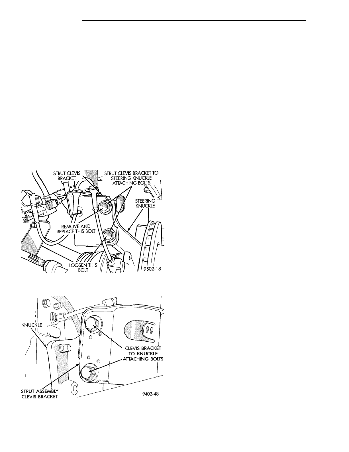
(3) Remove original upper bolt attaching the front
or rear strut clevis bracket to the steering knuckle or
rear knuckle (Fig. 2) or (Fig. 3).
Fig. 2 Front Strut Clevis Bracket To Steering
Knuckle Attaching Bolts
(4) Loosen lower bolt attaching strut clevis bracket
to steering knuckle or rear knuckle ONLY enough to
allow knuckle to move in clevis bracket.
(5) Install bolt from service kit into the upper
strut clevis bracket to steering knuckle or rear
knuckle mounting hole.
CAUTION: Only the nuts supplied in the service
kits MUST be used with the service kit replacement
bolts. The original nuts will not properly secure the
strut clevis bracket to steering knuckle or rear
knuckle.
(6) Install nut provided in service kit on the
replacement bolt.
(7) Tighten upper bolt and nut from service kit
until snug, but still allowing movement between
strut clevis bracket and knuckle.
(8) Remove original lower bolt. Install bolt from
service kit into the bottom hole of the strut clevis
bracket. Install nut and snug.
(9) Lower vehicle until full weight of vehicle is
supported by the suspension and then jounce front
and rear of vehicle an equal amount of times.
(10) Adjust front and or rear camber to the preferred setting by pushing or pulling on the top of the
front or rear tire. When camber is correctly set
tighten upper and lower strut clevis bracket bolts.
Again jounce front and rear of vehicle an equal
amount of times and verify front and rear camber
setting. See Alignment Specifications in this group of
the service manual for required specifications.
(11) When vehicle is at correct camber setting
torque both front strut clevis bracket to steering
knuckle attaching bolts to 53 N·m (40 ft. lbs.) plus an
additional 1/4 turn after required torque is met.
Torque rear strut clevis bracket to rear knuckle
attaching bolts to 95 N·m (70 ft. lbs.).
(12) If Toe readings obtained are not within the
required specification range, adjust Toe to meet the
preferred specification setting. Toe is adjustable
using the following Toe setting procedure.
Fig. 3 Rear Strut Clevis Bracket Attaching Bolts
FRONT AND REAR TOE SETTING PROCEDURE
(1) Prepare vehicle as described in the Pre-Alignment Vehicle Inspection procedure.
(2) Center steering wheel and lock in place using a
steering wheel clamp.
(3) When performing the Toe setting procedure, set
rear wheel Toe to preferred specification first, then
set front wheel Toe to the preferred specification.
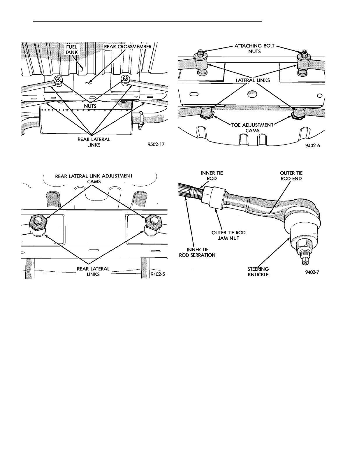
(4) Loosen nuts on attaching bolts, for the left and
right rear lateral links to rear crossmember (Fig. 4).
(5) Rotate lateral link adjustment cams (Fig. 5)
until the preferred rear Toe specification is obtained.
See Alignment Specifications in this group of the service manual for preferred specification.
Page 7
REAR LATERAL LINKADJUSTMENT CAMSREAR LATERAL LINKS
FUEL TANK
REAR CROSSMEMBERREAR LATERAL LINKSNUTS
ATTACHING BOLT NUTSLATERAL LINKSTOE ADJUSTMENTCAMS
PL SUSPENSION 2 - 7
SERVICE PROCEDURES (Continued)
Fig. 4 Rear Lateral Link To Crossmember Attaching
Bolts
Fig. 5 Rear Wheel Toe Adjustment Cams
(6) While holding Toe adjustment cams from turning, tighten left and right lateral links to rear crossmember attaching bolt nuts. This will securely hold
adjustment cams in position. Then while holding lateral link attaching bolt and adjustment cam from
turning, torque nut of lateral link attaching bolt to
95 N·m (70 ft. lbs.) (Fig. 6).
Fig. 6 Torquing Rear Lateral Link Attaching Bolts
Fig. 7 Front Wheel Toe Adjustment
(9) Adjust steering gear to tie rod boots at tie rod.
(10) Remove steering wheel clamp.
CAUTION: Do not twist front inner tie rod to steering gear rubber boots during front wheel Toe
adjustment.
(7) Loosen inner to outer tie rod end jam nuts (Fig.
7). Grasp inner tie rods at serrations and rotate tie
rods (Fig. 7) to set the front wheel Toe to the preferred specification. See Alignment Specifications in
this group of the service manual for preferred specification.
(8) Tighten tie rod locknuts to 54 N·m (40 ft.lbs.)
torque.
Page 8
2 - 8 SUSPENSION PL
SPECIFICATIONS
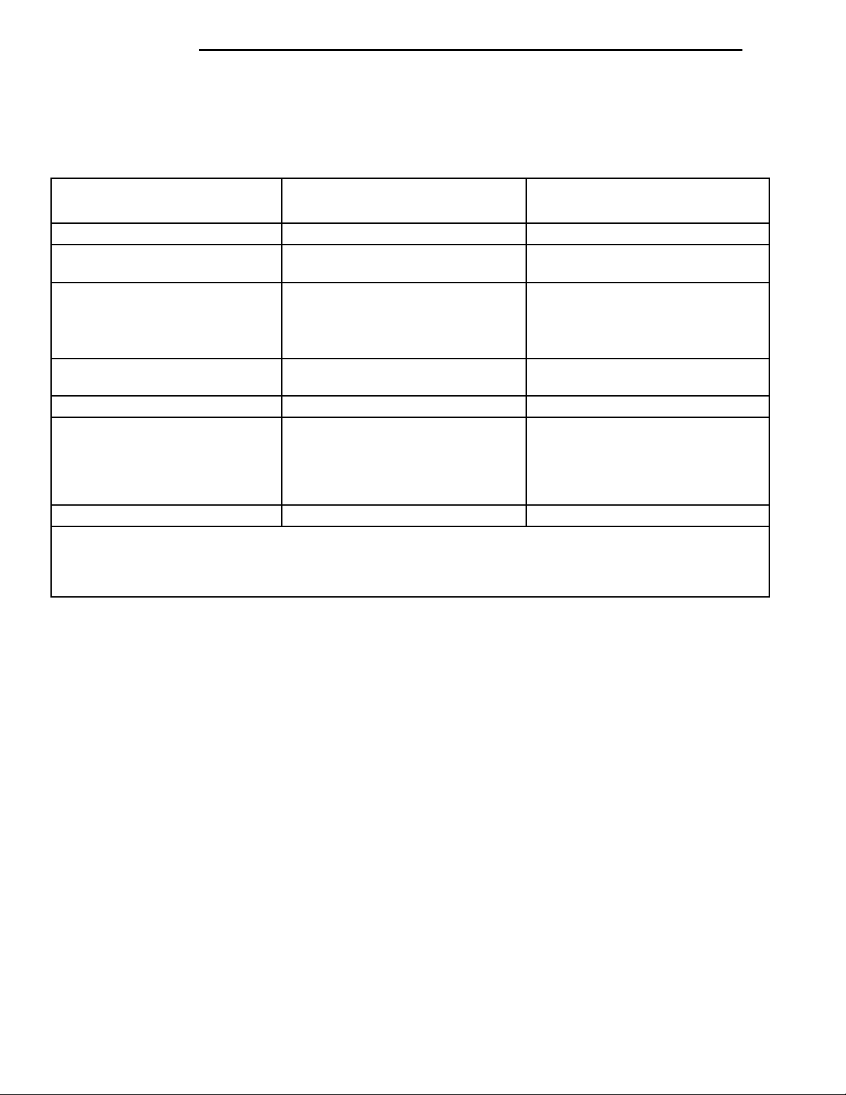
VEHICLE ALIGNMENT SPECIFICATIONS AT CURB HEIGHT
FRONT WHEEL ALIGNMENT
CAMBER ................... -0.4° to +0.4° +0.0°
TOTALTOE.................
Specified In Degrees (See Note)
CASTER* .................. +1.8° to +3.8°
*Side To Side Caster Difference
Not To Exceed ...............
REAR WHEEL ALIGNMENT ACCEPTABLE ALIGNMENT
CAMBER ................... -.75° to +0.25° -0.25°
TOTALTOE.................
Specified In Degrees (See Note)
TOE OUT: When Backed On
Alignment Rack Is TOE In When
Driving
THRUST ANGLE ............. -0.10° to +0.10°
Note: Total Toe is the arithmetic sum of the left and right wheel Toe settings. Positive is Toe-in, negative is
Toe-out. Total Toe must be equally split between each front wheel to ensure the steering wheel is centered after
setting Toe. Left and Right Toe
must be equal to within 0.02 degrees.
ACCEPTABLE ALIGNMENT
RANGE AT CURB HEIGHT
0.3°in to 0.1°out 0.1° in
+2.8°
1.0° or less
PREFERRE SETTING
RANGE AT CURB HEIGHT
0.3° in to 0.1° out 0.1° in
PREFERRE SETTING
Page 9
SHOCKTOWERNO SHEET METAL SCREWS,BOLTS, OR ANY OTHERMETAL FASTENERS ARE TOBE INSTALLED INTO SHOCKTOWER IN THIS AREA.ALSO, NO HOLES ARE TOBE DRILLED INTO SHOCKTOWER IN THIS SAMEAREA. COILSPRING
PL SUSPENSION 2 - 9
FRONT SUSPENSION
INDEX
page page
GENERAL INFORMATION
GENERAL INFORMATION ................. 9
DESCRIPTION AND OPERATION
BALL JOINT ........................... 13
COIL SPRING ......................... 13
FRONT SUSPENSION .................... 9
FRONT WHEEL HUB BEARING ............ 13
LOWER CONTROL ARM ................. 12
McPHERSON STRUT ASSEMBLY .......... 12
STABILIZER BAR ....................... 12
STEERING KNUCKLE ................... 12
WHEEL MOUNTING STUDS .............. 13
DIAGNOSIS AND TESTING
BALL JOINT ASSEMBLY .................. 14
HUB/BEARING ......................... 14
LOWER CONTROL ARM ................. 14
MCPHERSON STRUT ASSEMBLY .......... 13
STABILIZER BAR ....................... 14
STEERING KNUCKLE ................... 13
GENERAL INFORMATION
GENERAL INFORMATION
CAUTION: ONLY FRAME CONTACT HOISTING
EQUIPMENT CAN BE USED ON THIS VEHICLE. All
vehicles have a fully independent rear suspension.
The vehicles can not be hoisted using equipment
designed to lift a vehicle by the rear axle. If this
type of hoisting equipment is used, damage to rear
suspension components will occur.
REMOVAL AND INSTALLATION
FRONT WHEEL MOUNTING STUDS ........ 25
HUB BEARING ......................... 23
LOWER CONTROL ARM ................. 20
MCPHERSON STRUT ................... 15
STABILIZER BAR ....................... 22
STEERING KNUCKLE ................... 16
DISASSEMBLY AND ASSEMBLY
BALL JOINT ........................... 29
LOWER CONTROL ARM FRONT ISOLATOR
BUSHING ........................... 31
LOWER CONTROL ARM REAR ISOLATOR
BUSHING ........................... 32
McPHERSON STRUT .................... 27
SPECIFICATIONS
FRONT SUSPENSION FASTENER
TORQUES .......................... 33
SPECIAL TOOLS
FRONT SUSPENSION ................... 34
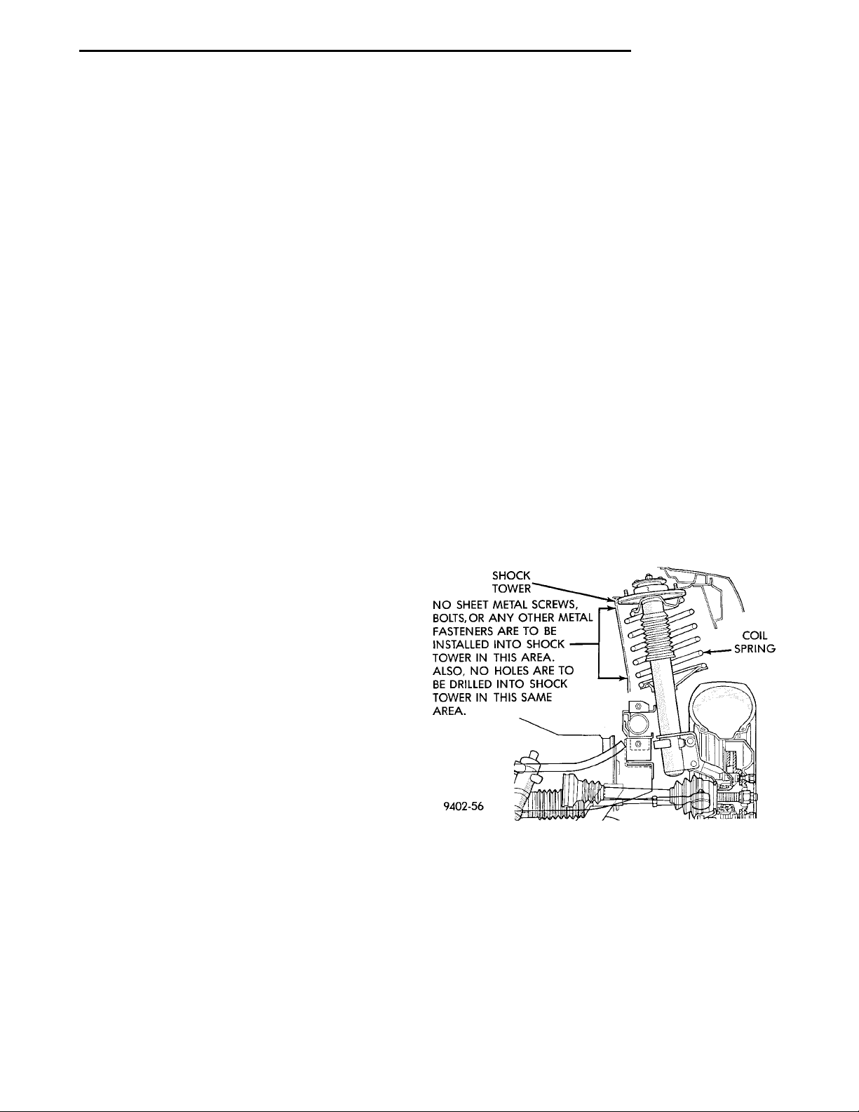
CAUTION: At no time when servicing a vehicle,
can a sheet metal screw, bolt or other metal fastener be installed in the shock tower to take the
place of an original plastic clip. Also, NO holes can
be drilled into the front shock tower in the area
shown in (Fig. 1), for the installation of any metal
fasteners into the shock tower.
Because of the minimum clearance in this area
(Fig. 1) installation of metal fasteners could damage
the coil spring coating and lead to a corrosion failure
of the spring. If a plastic clip is missing, or is lost or
broken during servicing a vehicle, replace only with
the equivalent part listed in the Mopar parts catalog.
DESCRIPTION AND OPERATION
FRONT SUSPENSION
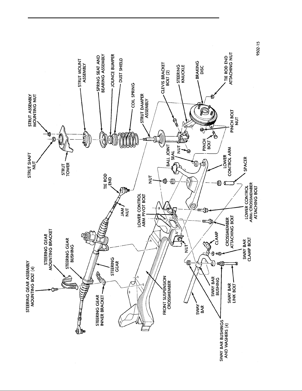
This vehicle has a gas pressurized MacPherson
strut front suspension design (Fig. 2).
Fig. 1 Shock Tower To Spring Minimum Clearance
Area
A MacPherson strut assembly is used in place of
the front suspension upper control arm and upper
ball joint. The bottom of the MacPherson strut,
mounts directly to the steering knuckle using 2
attaching bolts and nuts going through the clevis
Page 10

2 - 10 SUSPENSION PL
DESCRIPTION AND OPERATION (Continued)
bracket and steering knuckle (Fig. 2). The top of the
strut is mounted directly to the strut tower of the
vehicle by the strut mount assembly’s 3 studs and
attaching nuts (Fig. 2). During steering maneuvers,
the strut assembly (through a pivot bearing in the
upper strut mount assembly) and steering knuckle
(through the lower ball joint) turn as an assembly
(Fig. 2).
The MacPherson strut assembly includes the following components: A rubber isolated top mount, an
upper spring seat/bearing assembly, jounce bumper,
dust shield, coil spring with plastic noise insulator
and the strut dampener.
A cast lower control arm assembly (Fig. 2) is
attached to the front suspension crossmember using
2 rubber isolator bushings and to the steering
knuckle by means of a ball joint.
A sealed for life front hub and bearing assembly is
attached to the front steering knuckle. The outer C/V
joint assembly is splined to the front hub and bearing assembly and is retained by a prevailing torque
nut.
Page 11
PL SUSPENSION 2 - 11
DESCRIPTION AND OPERATION (Continued)
Fig. 2 Front Suspension (Typical)
Page 12
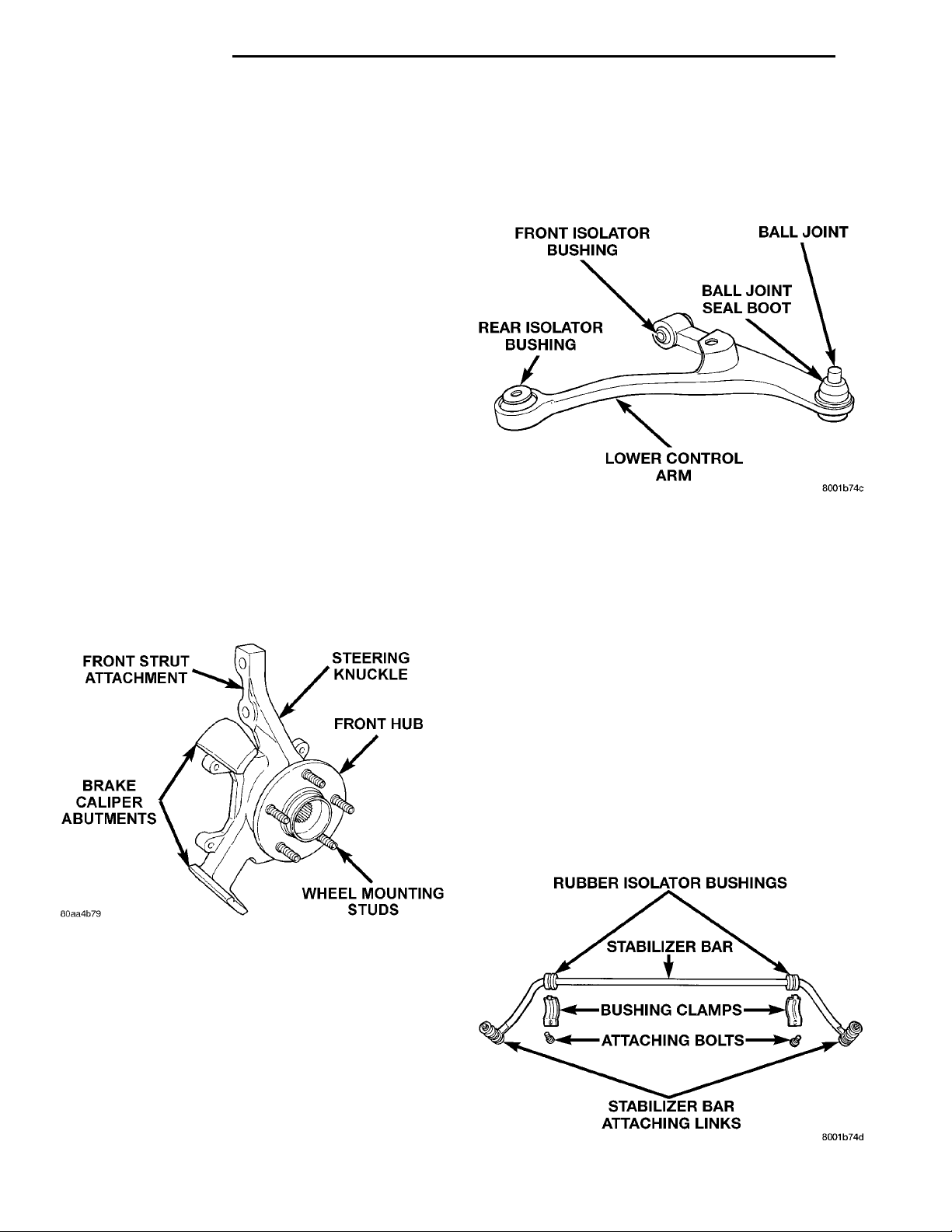
FRONT STRUT ATTACH-MENTSTEERING KNUCKLEFRONT HUBWHEEL MOUNTING STUDSBRAKE CALIPER ABUT-MENTS
FRONT ISOLATOR BUSHING BALL JOINTBALL JOINT SEALBOOTLOWER CONTROL ARMREAR ISOLATOR BUSHING
2 - 12 SUSPENSION PL
DESCRIPTION AND OPERATION (Continued)
McPHERSON STRUT ASSEMBLY
The front strut and suspension of the vehicle is
supported by coil springs positioned around the
struts. The springs are contained between an upper
seat, located just below the top strut mount assembly
and a lower spring seat on the strut lower housing.
The top of each strut assembly is bolted to the
upper fender reinforcement (shock tower) through a
rubber isolated mount.
The bottom of the strut assembly attaches to the
top of the steering knuckle using 2 thru-bolts and
prevailing torque nuts. Caster and camber is a fixed
setting (net build) on all vehicles and is not required
to be adjusted.
STEERING KNUCKLE
The steering knuckle (Fig. 3) is a single casting
with legs machined for attachment to the front strut
assembly and lower control arm ball joint. The steering knuckle also has machined abutments on the
casting to support and align the front brake caliper
assembly. The knuckle also holds the front drive
shaft outer C/V joint hub and bearing assembly. The
hub is positioned through the bearing and knuckle,
with the constant velocity stub shaft splined through
the hub. The outer C/V joint is retained to the hub/
bearing using a hub nut. The hub nut is held on the
stub shaft using a nut retainer and cotter pin.
through both the crossmember and rear lower control
arm bushing, threading directly into the frame rail of
the vehicle. The lower control arms are inter-connected through a linked rubber isolated stabilizer
bar.
Fig. 4 Lower Control Arm Assembly
STABILIZER BAR
The stabilizer bar (Fig. 5) interconnects both front
lower control arms of the vehicle and is attached to
the front suspension cradle.
Jounce and rebound movements affecting one
wheel are partially transmitted to the opposite wheel
of the vehicle to stabilize body roll.
Attachment of the stabilizer bar to the front suspension cradle is through 2 rubber-isolator bushings
and bushing retainers (Fig. 5). The stabilizer bar to
lower control arm attachment is done utilizing a rubber isolated stabilizer bar attaching link (Fig. 5). All
parts of the stabilizer bar are serviceable, and the
stabilizer bar to crossmember bushings are split for
easy removal and installation. The split in the stabilizer bar to crossmember bushing must be positioned
toward the front of the vehicle, when the stabilizer
bar is installed on the vehicle.
RUBBER ISOLATOR BUSHINGSSTABILIZER BARBUSHING CLAMPSATTACHING BOLTSSTABILIZER BAR ATTACHINGLINKS
Fig. 3 Steering Knuckle Assembly
LOWER CONTROL ARM
The lower control arm (Fig. 4) is a ductile iron
casting using 2 rubber bushings to isolate it from the
front suspension crossmember and frame of the vehicle. The isolator bushings consist of 2 metal encased
rubber isolated pivot bushings. The front of the lower
control arm is bolted to the front crossmember using
a bolt through the center of the rubber pivot bushing
(Fig. 4). The rear of the lower control arm is mounted
to both the front crossmember and the frame rail of
the vehicle using a thru-bolt. The thru-bolt goes
Fig. 5 Stabilizer Bar And Components
Page 13
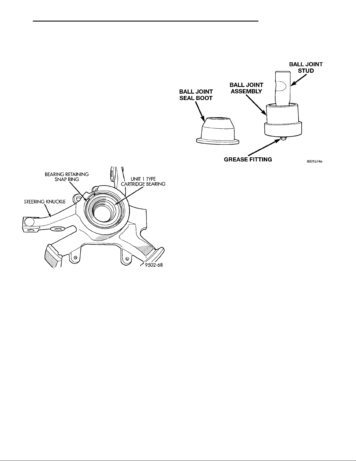
STEERING KNUCKLEBEARING RETAINING SNAPRING UNIT 1 TYPE CAR-TRIDGE BEARING
BALL JOINTSEAL BOOT BALL JOINT ASSEMBLY BALL JOINT STUDGREASE FITTING
PL SUSPENSION 2 - 13
DESCRIPTION AND OPERATION (Continued)
FRONT WHEEL HUB BEARING
The front wheel hub bearing used on the Neon is a
Unit 1 type cartridge bearing (Fig. 6).
The wheel bearing is serviced separately from the
front steering knuckle and front hub assembly.
Installation and retention of the front wheel bearing
into the steering knuckle, is by means of an interference press fit using a retaining compound and a
retaining snap ring (Fig. 6). Installation of the front
hub into the front wheel bearing, must be done after
wheel bearing and retaining snap ring is installed in
steering knuckle.
The unit 1 wheel bearing is serviced only as a complete assembly less the wheel hub. If the front wheel
bearing requires replacement, the hub must be
removed from the original wheel bearing and transferred to the replacement bearing.
Fig. 6 Front Wheel Hub Bearing
serviced as a separate component of the lower control
arm assembly.
Fig. 7 Ball Joint Assembly
WHEEL MOUNTING STUDS
If wheel attaching studs need to be replaced in the
hub and bearing assembly the studs CAN NOT be
hammered out of the hub flange. If a stud is removed
by hammering it out of the bearing flange, damage to
the hub and bearing assembly will occur leading to
premature bearing failure.
Use the procedure and special tools shown in the
service procedures section for the wheel mounting
studs when replacing the wheel attaching studs.
The hub and bearing assembly does not require
removal from the steering knuckle or the rear
knuckle to replace the wheel attaching studs in the
hub and bearing assembly.
COIL SPRING
Coil springs are rated separately for each corner or
side of the vehicle depending on optional equipment
and type of vehicle service. During service procedures
when both springs are removed, mark springs to
ensure installation in original position. Each coil
spring comes with a plastic sleeve on the second coil
of the spring. This plastic sleeve is a noise insulator
for the coil spring. If coil springs require replace-
ment, be sure that the springs needing replacement, are replaced with springs meeting the
correct load rating for the vehicle and its specific options.
BALL JOINT
The ball joint (Fig. 7) is pressed into the lower control arm and has a non-tapered stud with a notch for
steering knuckle clamp bolt clearance. The ball joint
stud is clamped and locked into the steering knuckle
leg using a pinch bolt. The ball joint used on this
vehicle is replaceable and if found defective can be
DIAGNOSIS AND TESTING
MCPHERSON STRUT ASSEMBLY
(1) Inspect for damaged or broken coil springs
(Fig. 8).
(2) Inspect for torn or damaged strut assembly
dust boots (Fig. 8).
(3) Lift dust boot (Fig. 9) and inspect strut assembly for evidence of fluid running from the upper end
of fluid reservoir. (Actual leakage will be a stream of
fluid running down the side and dripping off lower
end of unit). A slight amount of seepage between the
strut rod and strut shaft seal is not unusual and does
not affect performance of the strut assembly. Also
inspect jounce bumpers for signs of damage or deterioration.
STEERING KNUCKLE
The front suspension steering knuckle is not a
repairable component of the front suspension. IT
MUST BE REPLACED IF FOUND TO BE DAM-
Page 14
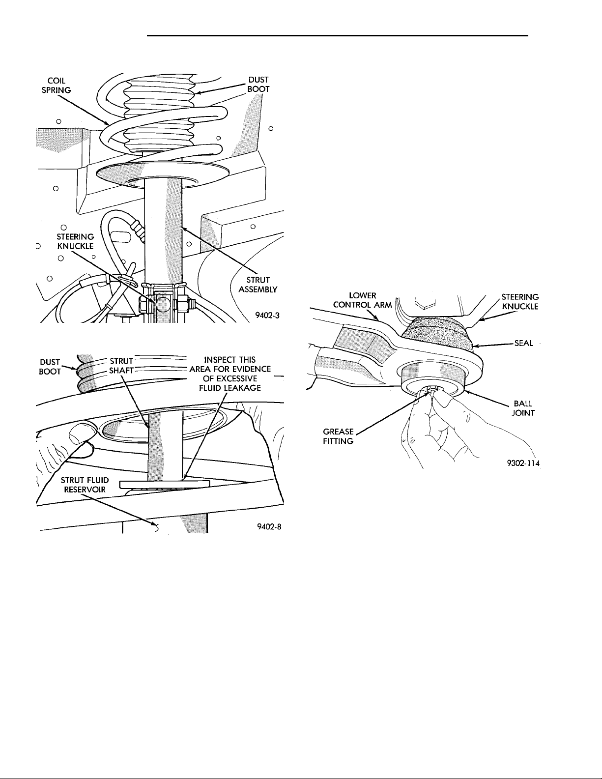
COIL SPRING DUST BOOTSTEERINGKNUCKLE STRUTASSEMBLY
2 - 14 SUSPENSION PL
DIAGNOSIS AND TESTING (Continued)
distortion. Do not attempt to repair or straighten
a broken or bent lower control arm.
The serviceable components of the lower control
arm are: the ball joint assembly, ball joint assembly
grease seal and control arm bushings. Inspect both
control arm bushings for severe deterioration, and
replace if required. Inspect ball joint per inspection
procedure in this section of the service manual and
replace if required. Service procedures to replace
these components are detailed in the specific component removal and installation sections in this group
of the service manual.
BALL JOINT ASSEMBLY
With the weight of the vehicle resting on the road
wheels. Grasp the grease fitting as shown in (Fig. 10)
and with no mechanical assistance or added force
attempt to move the grease fitting.
Fig. 8 McPherson Strut Assembly Inspection
Fig. 9 Strut Assembly Leakage Inspection
AGED IN ANY WAY. If it is determined that the
steering knuckle is bent when servicing the vehicle,
no attempt is to be made to straighten the steering
knuckle.
On this vehicle the steering knuckle must be
removed from the vehicle when servicing the front
hub bearing.
LOWER CONTROL ARM
If damaged, the lower control arm casting is serviced only as a complete component. Inspect lower
control arm for signs of damage from contact with
the ground or road debris. If lower control arm shows
any sign of damage, inspect lower control arm for
Fig. 10 Checking Ball Joint Wear
If the ball joint is worn the grease fitting will move
easily. If movement is noted, replacement of the ball
joint is recommended.
STABILIZER BAR
Inspect for broken or distorted sway bar bushings,
bushing retainers, and worn or damaged sway bar to
strut attaching links. If sway bar to front suspension
cradle bushing replacement is required, bushing can
be removed from sway bar by opening slit and peeling bushing off sway bar.
HUB/BEARING
The hub bearing is designed for the life of the vehicle and requires no type of periodic maintenance. The
following procedure may be used for diagnosing the
condition of the hub bearing.
With the wheel, disc brake caliper, and brake rotor
removed, rotate the wheel hub. Any roughness or
resistance to rotation may indicate dirt intrusion or a
Page 15
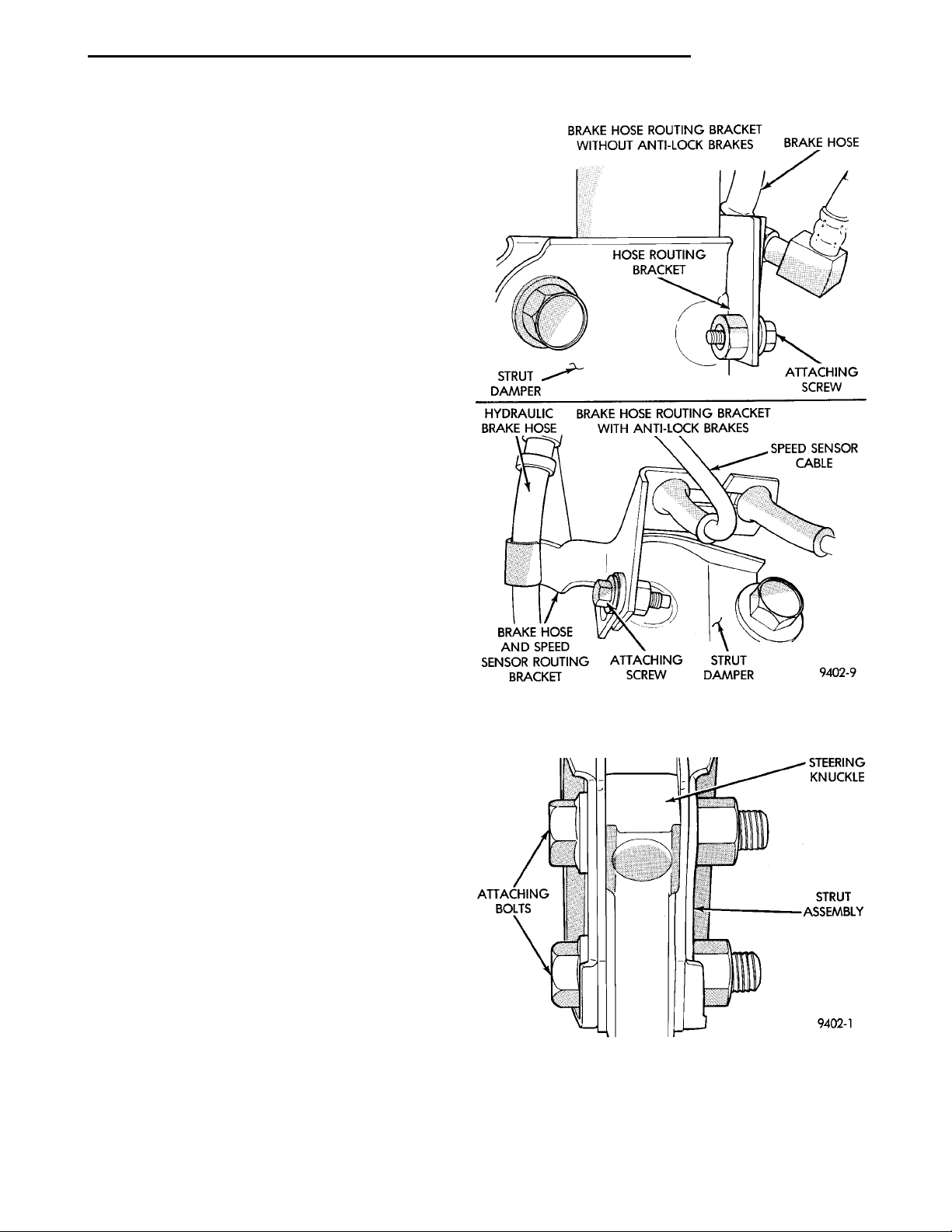
STRUTDAMPER BRAKE HOSE ROUTINGBRACKET WITHOUT ANTI-LOCK BRAKESHOSE ROUTING BRACKET BRAKE HOSEATTACHINGSCREWHYDRAULIC BRAKEHOSEBRAKE HOSE ANDSPEED SENSORROUTING BRACKET BRAKE HOSE ROUTINGBRACKET WITH ANTI-LOCKBRAKESATTACHINGSCREWSPEED SENSOR CABLESTRUT DAMPER
STEERINGKNUCKLESTRUTASSEMBLYATTACHINGBOLTS
PL SUSPENSION 2 - 15
DIAGNOSIS AND TESTING (Continued)
failed hub bearing. If the hub bearing exhibits any of
these conditions during diagnosis, the hub bearing
will require replacement, the bearing is not serviceable.
Damaged bearing seals and the resulting excessive
grease loss may also require bearing replacement.
Moderate grease weapage from the hub bearing is
considered normal and should not require replacement of the hub bearing.
REMOVAL AND INSTALLATION
MCPHERSON STRUT
REMOVE
WARNING: DO NOT REMOVE STRUT ROD NUT
WHILE STRUT ASSEMBLY IS INSTALLED IN VEHICLE, OR BEFORE STRUT ASSEMBLY SPRING IS
COMPRESSED.
(1) Loosen wheel nuts.
(2) Raise vehicle on jack stands or centered on a
frame contact type hoist. See Hoisting in the Lubrication and Maintenance section of this manual, for
the required lifting procedure to be used for this
vehicle.
(3) Remove wheel and tire assembly from location
on front of vehicle requiring strut removal.
(4) If both strut assemblies are removed, mark the
strut assemblies right or left according to which side
of the vehicle they were removed from.
(5) Remove hydraulic brake hose routing bracket
and attaching screw from strut damper bracket. If
vehicle is equipped with Anti-Lock brakes, hydraulic
hose routing bracket is combined with speed sensor
cable routing bracket (Fig. 11).
CAUTION: The steering knuckle to strut assembly
attaching bolts are serrated and must not be turned
during removal. Remove nuts while holding bolts
stationary in the steering knuckles.
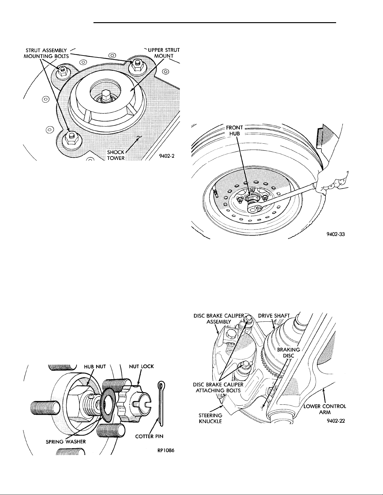
(6) Remove the 2 bolts (Fig. 12) attaching the strut
to the steering knuckle.
(7) Remove the 3 nuts attaching the upper mount
of the strut (Fig. 13) to the strut tower of the vehicle
.
Fig. 11 Brake Hose And Speed Sensor Cable
Routing Brackets
INSTALL
(1) Install strut assembly into strut tower, aligning
the 3 studs on the upper strut mount into the holes
in shock tower. Install the 3 upper strut mount
retaining nut and washer assemblies (Fig. 13).
Torque the 3 nuts to 31 N·m (23 ft. lbs.).
Fig. 12 Strut To Steering Knuckle Attaching Bolts
CAUTION: The steering knuckle to strut assembly
attaching bolts are serrated and must not be turned
during installation. Install nuts while holding bolts
stationary in the steering knuckles.
Page 16
DISC BRAKE CALIPERASSEMBLY DRIVE SHAFTBRAKINGDISC
STEERINGKNUCKLE LOWER CON-TROL ARM
STRUT ASSEMBLYMOUNTING BOLTS UPPERSTRUTMOUNT
HUB NUT
SHOCK
TOWER
NUT LOCKCOTTER PINSPRINGWASHER
DISC BRAKE CALIPER
ATTACHING BOLTS
FRONTHUB
2 - 16 SUSPENSION PL
REMOVAL AND INSTALLATION (Continued)
CAUTION: Wheel bearing damage will result if
after loosening hub nut, vehicle is rolled on the
ground or the weight of the vehicle is allowed to be
supported by the tires.
(2) Loosen hub nut while vehicle is on the floor
with the brakes applied (Fig. 15). The hub and
driveshaft are splined together through the
knuckle (bearing) and retained by the hub nut.
(3) Raise vehicle on jack stands or centered on a
Fig. 13 Strut To Shock Tower Mounting
(2) Align strut assembly with steering knuckle.
Position arm of steering knuckle into strut assembly,
aligning the strut assembly to steering knuckle
mounting holes. Install the 2 strut assembly to steering knuckle attaching bolts (Fig. 12). Attaching bolts
should be installed with the nuts facing the front of
the vehicle. Torque both attaching bolts to 53 N·m
(40 ft. lbs.) plus an additional 1/4 turn after specified
torque is met.
(3) Install hydraulic brake hose routing bracket
and attaching screw onto strut damper bracket. If
vehicle is equipped with Anti-Lock brakes, hydraulic
hose routing bracket is combined with speed sensor
cable routing bracket (Fig. 11). Torque bracket
attaching bolts (Fig. 11) to 13 N·m (10 ft. lbs.).
(4) Tighten the wheel mounting stud nuts in
proper sequence until all nuts are torqued to half
specification. Then repeat the tightening sequence to
the full specified torque of 135 N·m (100 ft. lbs.).
Fig. 15 Loosening Front Hub Retaining Nut
frame contact type hoist. See Hoisting in the Lubrication and Maintenance section of this manual, for
the required lifting procedure to be used for this
vehicle.
(4) Remove the front tire and wheel.
(5) Remove front disc brake caliper to steering
knuckle attaching bolts (Fig. 16).
STEERING KNUCKLE
REMOVE
(1) Remove cotter pin, nut lock, and spring washer
(Fig. 14).
Fig. 14 Cotter Pin, Nut Lock, And Spring Washer
Fig. 16 Disc Brake Caliper Attaching Bolts
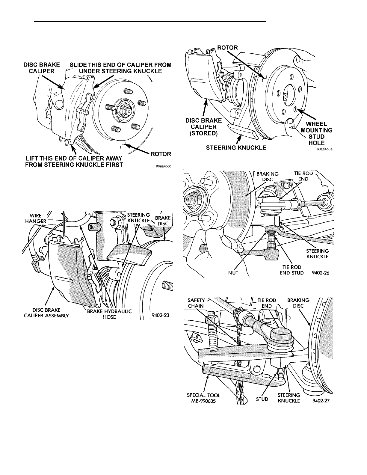
(6) Remove the disc brake caliper from the steering knuckle. Caliper is removed by first lifting bottom of caliper away from steering knuckle, and then
Page 17
DISC BRAKE CALIPERSLIDE THIS END OF CALI-PER FROM UNDER STEER-ING KNUCKLEROTORLIFT THIS END OF CALIPERAWAY FROM STEERINGKNUCKLE FIRST
WIREHANGER STEERINGKNUCKLE BRAKEDISCDISC BRAKE CALIPERASSEMBLY BRAKE HYDRAULICHOSE
SAFETYCHAIN
ROTORWHEEL MOUNTING STUDHOLESTEERING KNUCKLEDISC BRAKE CALIPER(STORED)
BRAKINGDISC
NUT TIE ROD END STUDSTEERINGKNUCKLE
TIE ROD
END
BRAKINGDISCSPECIAL TOOLMB-990635 STUD STEERINGKNUCKLE
TIE ROD END
PL SUSPENSION 2 - 17
REMOVAL AND INSTALLATION (Continued)
removing top of caliper out from under steering
knuckle (Fig. 17).
Fig. 19 Remove /Install Rotor
Fig. 17 Brake Caliper Removal
(7) Support brake disc brake caliper assembly
using a wire hook and not by hydraulic hose (Fig.
18).
Fig. 18 Supporting Brake Caliper
(8) Remove the rotor from the front hub/bearing
(Fig. 19).
(9) Remove the nut attaching outer tie rod end to
the steering knuckle (Fig. 20). Nut is to be
removed from tie rod end using the following
procedure, hold tie rod end stud with a 11/32
socket while loosening and removing nut with
wrench.
(10) Remove the tie rod end stud from steering
knuckle arm, using Remover, Special Tool
MB-990635 (Fig. 21).
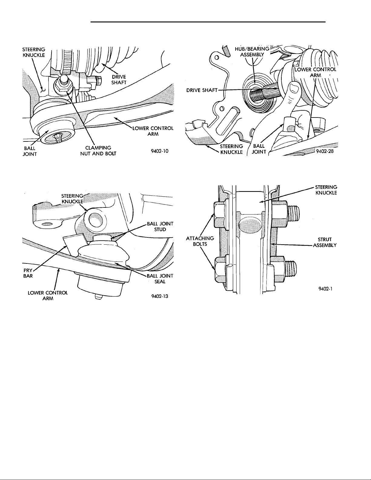
(11) Remove nut and bolt (Fig. 22), clamping ball
joint stud, from steering knuckle.
Fig. 20 Tie Rod End Attaching Nut
Fig. 21 Tie Rod End Removal From Steering
Knuckle
(12) Separate ball joint stud from steering knuckle
by prying down on lower control arm (Fig. 23). Note:
Use caution when separating ball joint stud
Page 18
STEERINGKNUCKLEBALLJOINT DRIVESHAFTCLAMPING NUT AND BOLTLOWER CONTROL ARM
STEERINGKNUCKLEPRY BARLOWER CONTROLARM BALL JOINTSTUDBALL JOINTSEAL
HUB/BEARINGASSEMBLYDRIVESHAFT LOWER CONTROLARMSTEERINGKNUCKLE BALLJOINT
STEERINGKNUCKLESTRUTASSEMBLYATTACHINGBOLTS
2 - 18 SUSPENSION PL
REMOVAL AND INSTALLATION (Continued)
Fig. 22 Steering Knuckle To Ball Joint Clamp Bolt
from steering knuckle, so ball joint seal does
not get cut.
Fig. 23 Separate Ball Joint Stud from Knuckle
Assembly
NOTE: Care must be taken not to separate the
inner C/V joint during this operation. Do not allow
driveshaft to hang by inner C/V joint, driveshaft
must be supported.
(13) Pull steering knuckle assembly out and away
from outer C/V joint of the driveshaft assembly (Fig.
24).
CAUTION: The steering knuckle to strut assembly
attaching bolts are serrated and must not be turned
during removal. Remove nuts while holding bolts
stationary in the steering knuckles.
(14) Remove the 2 steering knuckle to strut
damper clevis bracket attaching bolts (Fig. 25).
Fig. 24 Steering Knuckle Separation From
Driveshaft
Fig. 25 Remove Steering Knuckle To Strut Attaching
Bolts
(15) The cartridge type front wheel bearing
used on this vehicle is not transferable to the
replacement steering knuckle. If the replacement steering knuckle does not come with a
hub and bearing assembly, a new bearing must
be installed in the steering knuckle. Installation of the new wheel bearing must be done
before installing steering knuckle on vehicle.
Refer to Hub and Bearing Service in this section of
the service manual for proper wheel bearing removal
and installation procedure.
INSTALL
(1) Install a new cartridge hub and bearing assembly into the steering knuckle. Refer to Hub And Bearing Service in this section of the service manual for
proper wheel bearing removal and installation procedure.
Page 19
SLIDE TOP OF BRAKE CALI-PER UNDER TOP ABUT-MENT OF STEERINGKNUCKLE AS SHOWNBRAKING DISCDISC BRAKE CALIPERSTEERING KNUCKLE BRAKEABUTMENT
PL SUSPENSION 2 - 19
REMOVAL AND INSTALLATION (Continued)
CAUTION: The steering knuckle to strut assembly
attaching bolts are serrated and must not be turned
during installation. Install nuts while holding bolts
stationary in the steering knuckles.
(2) Install steering knuckle back in clevis bracket
of strut damper assembly (Fig. 25). Install the strut
damper to steering knuckle attaching bolts. Note:
The steering knuckle to strut assembly attaching bolts are serrated and must not be turned
in steering knuckle during installation. Torque
attaching nuts to 54 N·m (40 ft. lbs.) plus an additional 1/4 turn after specified torque is met.
(3) Slide drive shaft back into front hub and bearing assembly. Then install steering knuckle onto the
ball joint stud (Fig. 24).
(4) Install a NEW steering knuckle to ball joint
stud, clamp bolt and nut (Fig. 22). Torque the clamp
bolt to 100 N·m (75 ft. lbs.).
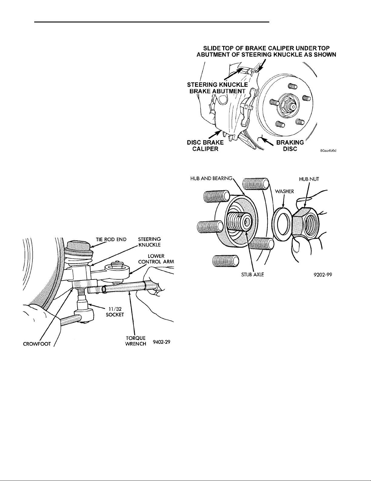
(5) Install tie rod end into the steering knuckle.
Start tie rod end to steering knuckle attaching nut
onto stud of tie rod end. While holding stud of tie rod
end stationary, tighten tie rod end to steering
knuckle attaching nut (Fig. 20). Then using a crowfoot and 11/32 socket (Fig. 26), torque tie rod end
attaching nut to 55 N·m (40 ft. lbs.).
Fig. 27 Brake Caliper Installation
Fig. 26 Torquing Tie Rod End Attaching Nut
(6) Install the rotor on the hub/bearing (Fig. 19).
(7) Install the disc brake caliper on the steering
knuckle. Caliper is installed by first sliding top of
caliper under top abutment on steering knuckle.
Then installing bottom of caliper against bottom
abutment of steering knuckle (Fig. 27).
(8) Install the disc brake caliper to steering
knuckle attaching bolts (Fig. 16). Tighten the caliper
attaching bolts to a torque of 31 N·m (23 ft. lbs.).
(9) Clean all foreign matter from the threads of
the outer C/V joint stub axle (Fig. 28). Install hub
nut onto threads of stub axle and tighten nut.
Fig. 28 Front Hub To Stub Shaft Nut
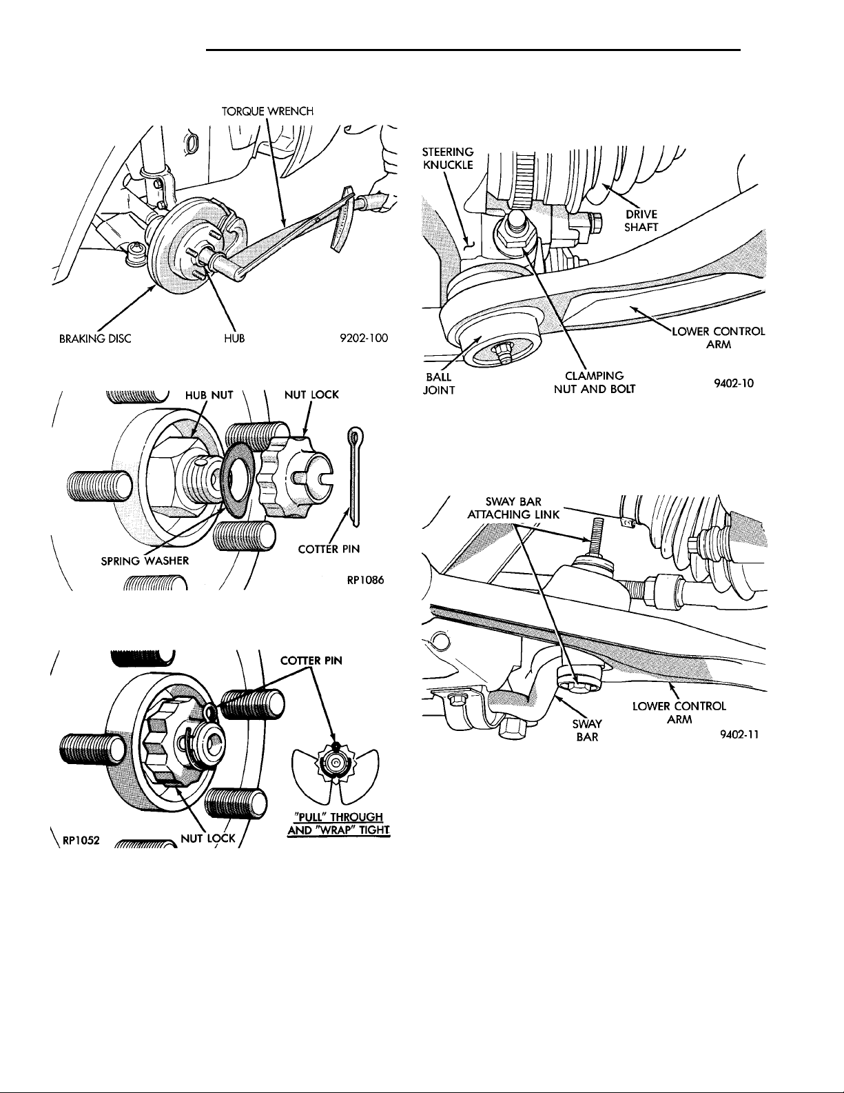
(10) With vehicle brakes applied to keep braking
disc from turning, tighten hub nut to a torque of 183
N·m (135 ft. lbs.) (Fig. 29).
(11) Install front wheel and tire assembly. Install
front wheel lug nuts and torque to 135 N·m (100 ft.
lbs.).
(12) Lower vehicle.
(13) Install the spring washer, hub nut lock, and
new cotter pin (Fig. 30). Wrap cotter pin prongs
tightly around the hub nut lock (Fig. 31).
(14) Set front Toe on vehicle to required specification. Use procedure listed under Wheel Alignment, in
the Front Suspension Service Procedures section of
this service manual.
Page 20
HUB NUT
TORQUE WRENCHHUBBRAKING DISC
NUT LOCKCOTTER PINSPRINGWASHER
COTTER PIN“PULL” THROUGH AND“WRAP” TIGHTNUT LOCK
2 - 20 SUSPENSION PL
REMOVAL AND INSTALLATION (Continued)
(2) Remove the steering knuckle to ball joint ball
stud, clamping nut and bolt (Fig. 32).
Fig. 29 Torquing Front Hub Nut
Fig. 30 Spring Washer, Nut Lock, And New Cotter
Pin
Fig. 31 Cotter Pin Correctly Installed
LOWER CONTROL ARM
REMOVE
(1) Raise vehicle on jack stands or centered on a
frame contact type hoist. See Hoisting in the Lubrication and Maintenance section of this manual for
the required lifting procedure to be used. Remove
wheel and tire assembly from side of vehicle requiring service to lower control arm.
Fig. 32 Control Arm To Steering Knuckle
Attachment
(3) Remove the 2 attaching links connecting the
stabilizer bar to the lower control arms (Fig. 33).
Fig. 33 Stabilizer Bar Link To Lower Control Arm
Attachment
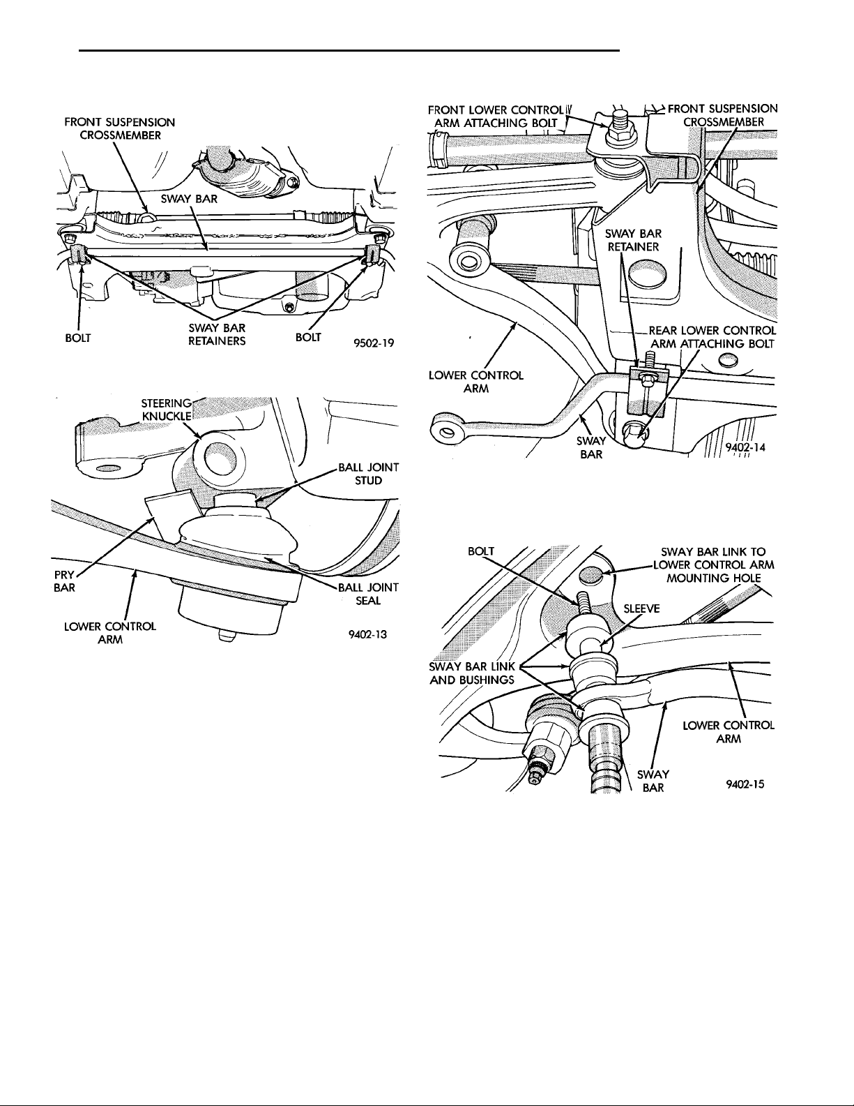
(4) Loosen but do not remove bolts attaching stabilizer bar retainers to front suspension crossmember
(Fig. 34). Then rotate stabilizer bar and attaching
links away from lower control arms
CAUTION: Pulling steering knuckle out from vehicle after releasing from ball joint can separate inner
C/V joint. See Driveshafts.
(5) Using a pry bar, separate steering knuckle
from ball joint stud (Fig. 35). Use caution when
separating ball joint stud from steering
knuckle, so ball joint seal does not get cut.
Page 21
FRONT SUSPENSIONCROSSMEMBER
SWAY BAR
BOLTSWAY BAR RETAINERSBOLT
FRONT LOWER CONTROL ARMATTACHING BOLT
SWAY BARRETAINERLOWER CONTROL ARM REAR LOWER CONTROLARM ATTACHING BOLTSWAY BAR
FRONT SUSPENSION
CROSSMEMBER
PL SUSPENSION 2 - 21
REMOVAL AND INSTALLATION (Continued)
Fig. 34 Stabilizer Bar To Crossmember Retainers
Fig. 35 Ball Joint Separation From Steering Knuckle
(6) Remove front lower control arm bushing to
crossmember attaching nut and bolt (Fig. 36).
Remove rear lower control arm to crossmember and
frame rail attaching bolt (Fig. 36). Then remove
lower control arm from crossmember.
INSTALL
(1) Position lower control arm into front crossmember. Then install rear lower control arm to crossmember and frame rail attaching bolt (Fig. 36). Do not
tighten rear attaching bolt at this time . Then
install front lower control arm to crossmember nut
and bolt (Fig. 36).
(2) Torque front lower control arm nut and bolt to
163 N·m (120 ft. lbs.), first and then torque rear
lower control arm attaching bolt to same torque specification.
(3) Install ball joint stud into steering knuckle.
Then install steering knuckle to ball joint stud
clamping bolt and nut (Fig. 32). Torque clamping bolt
to 95 N·m (70 ft. lbs.).
Fig. 36 Lower Control Arm Attaching Bolts
(4) Assemble stabilizer bar to lower control arm
link assemblies and bushings as shown in (Fig. 37).
Fig. 37 Assembled Stabilizer Bar Link And Bushings
(5) Rotate stabilizer bar into position, installing
the stabilizer bar link assemblies into the lower control arms. Then install the top stabilizer bar link
bushings and nuts (Fig. 38). DO NOT TIGHTEN
LINK ASSEMBLIES AT THIS TIME
(6) Lower vehicle so suspension is supporting the
total weight of the vehicle.
(7) Torque the stabilizer bar to lower control arm
link assemblies (Fig. 38) to 28 N·m (21 ft. lbs.).
Page 22
2 - 22 SUSPENSION PL
REMOVAL AND INSTALLATION (Continued)
retainers, stabilizer bar, and bushings from front
crossmember.
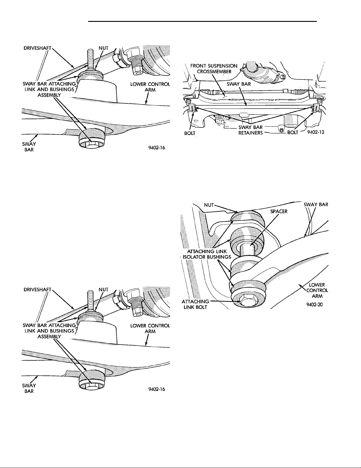
Fig. 40 Front Stabilizer Bar Bushing Retainers
INSTALL
Fig. 38 Installed Stabilizer Bar To Lower Control
Arm Attaching Link
(8) Torque the 2 stabilizer bar bushing retainer, to
crossmember attaching bolts (Fig. 34) to 28 N·m (21
ft. lbs.).
(1) If inspection determines replacement of stabilizer bar to lower control arm attachment link bushings is required, replace bushings before installing
stabilizer bar. Refer to (Fig. 41) for proper orientation
of attaching link bushing components.
STABILIZER BAR
REMOVE
(1) Raise vehicle on jack stands or centered on a
frame contact type hoist. See Hoisting in the Lubrication and Maintenance section of this manual, for
the required lifting procedure to be used for this
vehicle.
(2) Remove nuts and stabilizer bar attaching link
assemblies from the front lower control arms (Fig.
39).
(3) Remove bolts at front crossmember to stabilizer
bar bushing retainers (Fig. 40). Then remove bushing
DRIVESHAFT NUTSWAY BAR ATTACHING LINKAND BUSHINGS ASSEMBLY LOWER CONTROLARMSWAY BAR
Fig. 39 Sabilizer Bar To Lower Control Arm
Attaching Links
Fig. 41 Stabilizer Bar Attaching Link Assembly
Bushing Orientation
(2) If stabilizer bar to front crossmember bushings
require replacement at time of inspection, install new
bushings before installing stabilizer bar. Bushings
are replaced by opening slit on bushings and peeling
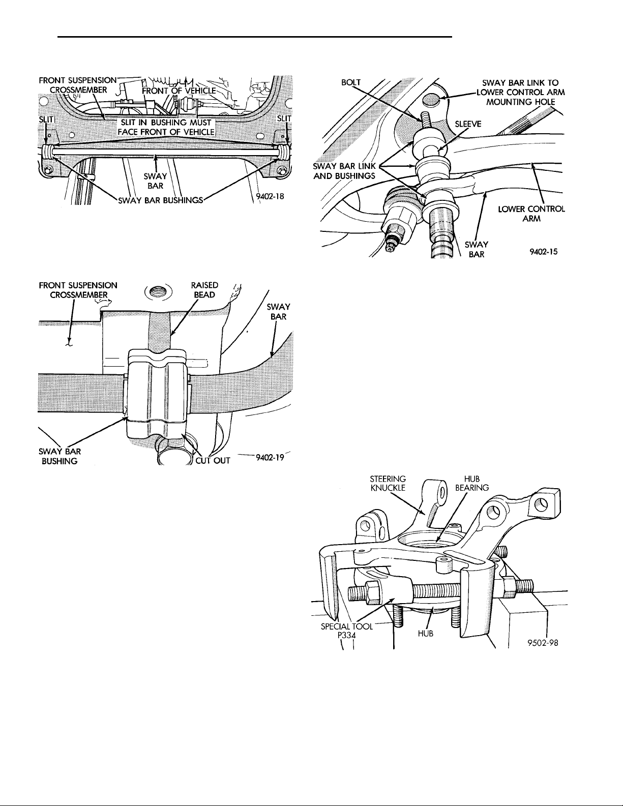
them off stabilizer bar. Install new bushings on stabilizer bar, by spreading bushing at slit and forcing
them on stabilizer bar. Bushings must be installed
on stabilizer bar with slit in bushing facing
front of vehicle when stabilizer bar is installed
(Fig. 42).
(3) Position stabilizer bar into front crossmember,
so cutouts in stabilizer bar bushings are aligned with
raised bead in crossmember. Install stabilizer bar
bushing retainers onto crossmember aligning raised
bead on retainer with cutouts in bushings (Fig. 43).
Page 23
FRONT SUSPENSION
CROSSMEMBER
SWAY BAR BUSHINGS
FRONT OF VEHICLESLIT IN BUSHING MUST FACE FRONT OF
SWAY BAR
VEHICLE
SLITSLIT
BOLT
SWAY BAR LINK AND
BUSHINGS
SLEEVESWAY BAR
LOWER CONTROLARM
SWAY BAR LINK TO LOWER CON-
TROL ARM MOUNTING HOLE
PL SUSPENSION 2 - 23
REMOVAL AND INSTALLATION (Continued)
Fig. 42 Correct Stabilizer Bar To Crossmember
Bushing Installation
Do not tighten stabilizer bar bushing retainers
at this time.
Fig. 44 Stabilizer Bar Link To Control Arm
Attachment
The removal and installation of the steering
knuckle hub bearing is to ONLY be done with
the steering knuckle removed from the vehicle.
Removal of the hub bearing from the steering
knuckle MUST be done using an arbor press
and the following procedure.
(2) Install Bearing Splitter, Special Tool P334 on
the steering knuckle and hub/bearing assembly as
shown in (Fig. 45) to support steering knuckle when
pressing out hub.
(3) Position steering knuckle and hub and bearing
in an arbor press supported by Bearing Splitter, Special Tool P334 as shown in (Fig. 45).
STEERING KNUCKLE HUB BEARINGHUBSPECIAL TOOLP334
Fig. 43 Stabilizer Bar To Crossmember Bushing
Position
(4) Align stabilizer bar attaching link and bushing
assemblies with attaching link mounting holes in the
lower control arms (Fig. 44). Install stabilizer bar
attaching links into both lower control arms. Install
the attaching link to stabilizer bar bushing and
retaining nut. Torque the stabilizer bar attaching
link nut (Fig. 44) to 28 N·m (21 ft. lbs.).
(5) Lower vehicle so the suspension is supporting
the total weight of the vehicle.
(6) With lower control arms of the vehicle at curb
height, tighten stabilizer bar bushing to crossmember
retainer attaching bolts to 28 N·m (21 ft. lbs.) torque.
HUB BEARING
REMOVE
(1) Remove the steering knuckle, hub and the hub
bearing as an assembly from the vehicle. Refer to
Steering Knuckle in the Removal And Installation
section in this group of the service manual for the
required steering knuckle removal procedure.
Fig. 45 Supporting Steering Knuckle For Hub
Removal
(4) Position Driver, Special Tool 6644-2 on the
small end of the hub to drive hub out of bearing.
Using arbor press remove hub from bearing. The one
bearing race will come out with hub when hub is
removed from bearing.
Page 24
SCREWDRIVER SNAPRING STEERINGKNUCKLEHUB BEAR-ING
ARBOR PRESSSPECIAL TOOL MB-990799 STEERINGKNUCKLEPRESS BLOCKS
ARBOR PRESSSPECIAL TOOL 6644–2 HUBSPECIAL TOOLP334BEARING RACEPRESS BLOCKS(2)
2 - 24 SUSPENSION PL
REMOVAL AND INSTALLATION (Continued)
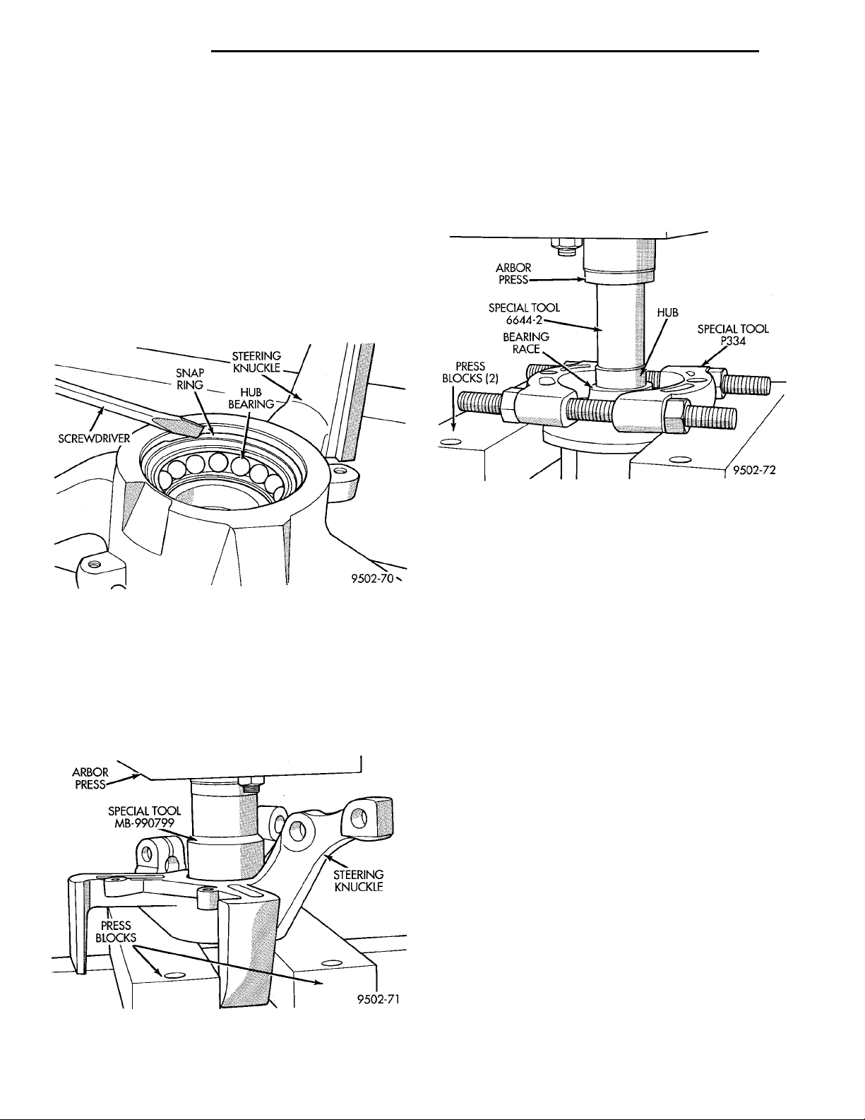
(5) Remove Bearing Splitter, Special Tool P334
from the steering knuckle.
CAUTION: Safety goggles and or face protection
should always be worn when removing the snap
ring (Fig. 46) retaining the hub/bearing in the steering knuckle. When the snap ring is removed from
the steering knuckle it could fly out of the steering
knuckle with great force possibly causing personal
injury.
(6) Using a screw driver, (Fig. 46) remove the snap
ring retaining the hub bearing in the steering
knuckle.
(8) Install Bearing Splitter, Special Tool P334 on
hub so it is between the flange of the hub and the
bearing race remaining on the hub (Fig. 48). Place
hub, bearing race and the bearing splitter in an
arbor press as shown in (Fig. 48). Place Driver, Special Tool 6644-2 on end of hub (Fig. 48). Press the
hub out of the bearing race.
Fig. 48 Removing Bearing Race From Hub
INSTALL
(1) Wipe bore of steering knuckle clean of any
grease or dirt with a clean dry shop towel.
Fig. 46 Hub Bearing Retaining Snap Ring Removal
(7) Place steering knuckle in an arbor press (Fig.
47) supported by press blocks as shown. Press blocks
must not obstruct hub bearing bore in steering
knuckle so bearing can be pressed out of knuckle.
Place Bearing Driver, Special Tool MB-990799 on
outer race of hub bearing (Fig. 47). Press hub bearing
completely out of the steering knuckle.
Fig. 47 Hub Bearing Removal From Steering
Knuckle
CAUTION: Do not use any type of solvent on the
hub bearing when cleaning it.
CAUTION: The hub bearing must be wiped as clean
as possible. Any remaining rust preventative on the
bearing can effect the bonding action of the adhesive to the bearing.
(2) Clean the rust preventative from the replacement hub bearing using a clean dry shop towel.
CAUTION: When applying adhesive to bore of
steering knuckle, do not allow adhesive to get into
the snap ring in bore or on the seal of the hub bearing
(3) Apply Loctite Adhesive # 640 or an equivalent,
to the bore of the steering knuckle. The adhesive is
to be applied to the entire bore wall suface, from the
shoulder at the bottom to just below the snap ring
groove.
(4) Place new hub bearing into bore of steering
knuckle. Be sure the bearing is square with the bore.
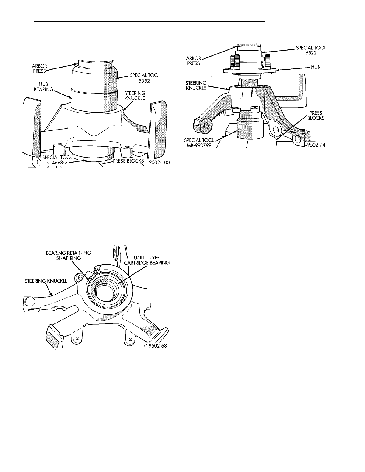
Place the steering knuckle in an arbor press with
Receiver, Special Tool C-4698-2 supporting steering
knuckle (Fig. 49). Place Diver, Special Tool 5052 (Fig.
49) on the outer race of the hub bearing. Press the
Page 25
PL SUSPENSION 2 - 25
REMOVAL AND INSTALLATION (Continued)
hub bearing into the steering knuckle until it is fully
bottomed in the bore of the steering knuckle.
Fig. 51 Pressing Hub Into Hub Bearing
section in this group of the service manual for the
Fig. 49 Pressing Hub Bearing Into Steering Knuckle
CAUTION: When installing the retaining snap ring
for the hub bearing care must be taken not to damage seal on new hub bearing.
(5) Install hub bearing retaining snap ring into
snap ring groove in hub bearing bore of steering
knuckle (Fig. 50). Be sure snap ring is fully seated in
snap ring groove.
required steering knuckle installation procedure.
(8) Install the wheel and tire on the vehicle.
(9) Lower the vehicle.
(10) Set the front wheel Toe to the required specification. Refer to Wheel Alignment Check And
Adjustment Procedure in the Service Procedures Section in this group of the service manual.
CAUTION: After the vehicle is aligned it can only
be moved a short distance and then parked. Do not
move the vehicle any further until the adhesive has
cured for a minimum of two hours. Driving the vehicle before the adhesive is allowed to cure properly,
will affect the retention of the bearing in the bore of
the steering knuckle.
Fig. 50 Hub Bearing Retaining Snap Ring Installed
(6) Place steering knuckle with hub bearing
installed in an arbor press with Receiver, Special
Tool MB-990799 supporting inner race of the hub
bearing (Fig. 51). Place hub in nub bearing making
sure it is square with bearing. Place Driver, Special
Tool 6522 on front face of hub (Fig. 51). Press the
hub into the hub bearing until hub is fully bottomed
in hub bearing.
(7) Install the steering knuckle, hub and the hub
bearing as an assembly on the vehicle. Refer to
Steering Knuckle in the Removal And Installation
FRONT WHEEL MOUNTING STUDS
CAUTION: If a wheel attaching stud needs to be
replaced in the front hub/bearing, the stud CAN
NOT be hammered out of the hub flange. If the stud
is removed by hammering it out of the bearing
flange, damage to the hub bearing will occur leading to premature bearing failure.
The following procedure and special tools shown
MUST be used when replacing wheel attaching
studs.
The hub and bearing assembly does not require
removal from the steering knuckle to replace wheel
attaching studs in the hub and bearing assembly.
REMOVE
(1) Raise vehicle on jackstands or centered on a
frame contact type hoist. See Hoisting in the Lubrication and Maintenance section of this manual, for
the required lifting procedure to be used for this
vehicle.
Page 26
DISC BRAKE CALIPERASSEMBLY DRIVE SHAFTBRAKINGDISC
STEERINGKNUCKLE LOWER CON-TROL ARM
DISC BRAKE CALI-PER ASSEMBLYBRAKINGDISC SLIDE THIS END OF CALIPER FROMUNDER STEERING KNUCKLE
DISC BRAKE CALIPER
LIFT THIS END OF
ATTACHING BOLTS
CALIPER AWAY
FROM STEERING
KNUCKLE FIRST
2 - 26 SUSPENSION PL
WIREHANGER STEERINGKNUCKLE BRAKEDISCDISC BRAKE CALIPERASSEMBLY BRAKE HYDRAULICHOSE
SPECIAL TOOL C-4150ALUG NUTHUB/BEARINGSTEERING KNUCKLEWHEEL STUD
ROTORWHEEL MOUNTING STUDHOLESTEERING KNUCKLEDISC BRAKE CALIPER(STORED)
REMOVAL AND INSTALLATION (Continued)
(2) Remove the front wheel and tire.
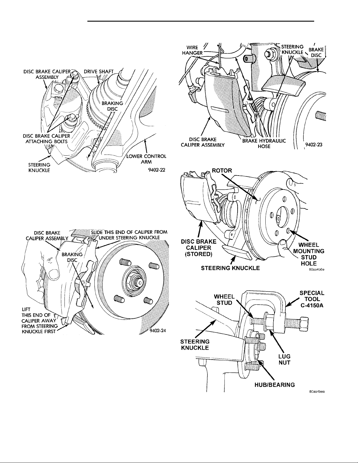
(3) Remove the 2 bolts (Fig. 52) attaching the disc
brake caliper to the steering knuckle .
Fig. 54 Correctly Supported Brake Caliper
Fig. 52 Caliper Attaching Bolts
(4) Remove the disc brake caliper from the steering knuckle. Caliper is removed by first lifting bottom of caliper away from steering knuckle, and then
removing top of caliper out from under steering
knuckle (Fig. 53).
Fig. 53 Brake Caliper Removal
(5) Support the disc brake caliper using a wire
hook, (Fig. 54) not by the hydraulic flex hose.
(6) Remove the rotor from the front hub (Fig. 55).
(7) Install a lug nut on the wheel stud being
removed from the hub/bearing, so threads on stud
are even with end of lug nut (Fig. 56). Rotate hub so
stud requiring removal is aligned with notch cast
into front of steering knuckle. Install Remover, Special Tool C-4150 on hub/bearing flange and wheel
stud (Fig. 56).
Fig. 55 Remove/Install Rotor
Fig. 56 Removing Wheel Stud From Hub/Bearing
Page 27
STEERINGKNUCKLE BRAKEABUTMENT BRAKINGDISCDISC BRAKE CALIPERASSEMBLY
STEERING KNUCKLEWHEEL LUG NUTWASHERSHUB/BEARING
SLIDE TOP OF BRAKE CALIPER UNDER TOP ABUTMENT OF STEERING
KNUCKLE AS SHOWN
STRUT ASSEMBLYVISESTRUT CLEVISBRACKET
PL SUSPENSION 2 - 27
REMOVAL AND INSTALLATION (Continued)
(8) Tighten Special Tool C-4150, pushing the wheel
stud out of the hub and bearing flange. When shoulder of wheel stud is past flange remove special tool
from hub/bearing. Remove lug nut from stud and
remove stud from flange.
INSTALL
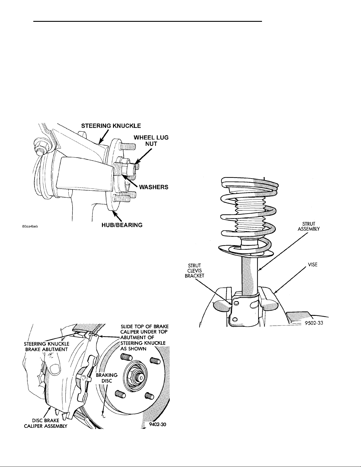
(1) Install replacement stud in flange of hub/bearing. Install washers and wheel lug nut on stud (Fig.
57). Lug nut MUST be installed with the flat side of
the lug nut against the washers (Fig. 57).
(5) Install the disc brake caliper to steering
knuckle attaching bolts (Fig. 53). Tighten the attaching bolts to a torque of 31 N·m (23 ft. lbs.).
(6) Install front wheel and tire. Install front wheel
lug nuts and torque to 135 N·m
(7) (100 ft. lbs.).
(8) Lower vehicle.
DISASSEMBLY AND ASSEMBLY
McPHERSON STRUT
DISASSEMBLY
(1) Clamp the strut assembly in a vise, with the
strut in a vertical position. When clamping the
strut assembly in the vise, do not clamp strut
using the body of the strut only by strut clevis
bracket (Fig. 59).
Fig. 57 Installing Wheel Stud
(2) Tighten the wheel lug nut. This will pull the
wheel stud into the flange of the hub/bearing. When
the head of the stud is fully seated against the bearing flange, remove the lug nut and washers from the
stud.
(3) Install rotor on front hub (Fig. 55).
(4) Install disc brake caliper on steering knuckle.
Caliper is installed by first sliding top of caliper
under top abutment on steering knuckle. Then install
bottom of caliper against bottom abutment on steering knuckle (Fig. 58).
Fig. 59 Strut Assembly Correctly Clamped In Vise
(2) Mark coil spring and strut assembly right or
left, according to which side of the vehicle the strut
was removed from, and which strut coil spring was
removed from.
WARNING: DO NOT REMOVE STRUT ROD NUT,
BEFORE STRUT ASSEMBLY COIL SPRING IS COMPRESSED, REMOVING SPRING TENSION FROM
UPPER SPRING SEAT AND BEARING ASSEMBLY.
Fig. 58 Disc Brake Caliper Installation
Page 28
SPECIAL TOOL C-483810 MM SOCKETSTRUT MOUNTSPECIALTOOL L-4558A
SPECIAL TOOL C-4838STRUT ASSEMBLYCOIL SPRINGSTRUT ASSEMBLY
2 - 28 SUSPENSION PL
SPECIAL TOOL C-4838UPPER STRUT MOUNTUPPERSPRING SEAT
PIVOT BEARINGUPPER SPRING SEATDUST BOOTCOILSPRING
DISASSEMBLY AND ASSEMBLY (Continued)
WARNING: WHEN COMPRESSING COIL SPRING
FOR REMOVAL FROM STRUT ASSEMBLY, THE
FIRST FULL TOP AND BOTTOM COIL OF THE COIL
SPRING MUST BE CAPTURED BY THE JAWS OF
THE COIL SPRING COMPRESSOR (Fig. 60).
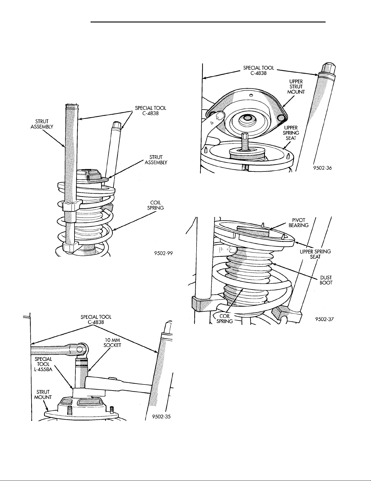
(3) Compress the strut assembly coil spring, using
Spring Compressor, Special Tool C-4838 (Fig. 60).
(5) Remove the strut assembly mount/isolator (Fig.
62) from the strut.
Fig. 62 Strut Mount
(6) Remove the upper spring seat, pivot bearing
and dust shield as an assembly (Fig. 63) from the
strut.
Fig. 60 Compressing Strut Assembly Coil Spring
(4) Install Socket, Strut Nut, Special Tool L-4558A
(or L-4558) on the strut shaft retaining nut (Fig. 61).
Then install a 10 mm socket on the hex of the strut
damper shaft (Fig. 61). While holding strut shaft
from turning, remove the strut shaft retaining nut.
Fig. 61 Strut Shaft Retaining Nut Removal Tools
Fig. 63 Upper Spring Seat Assembly
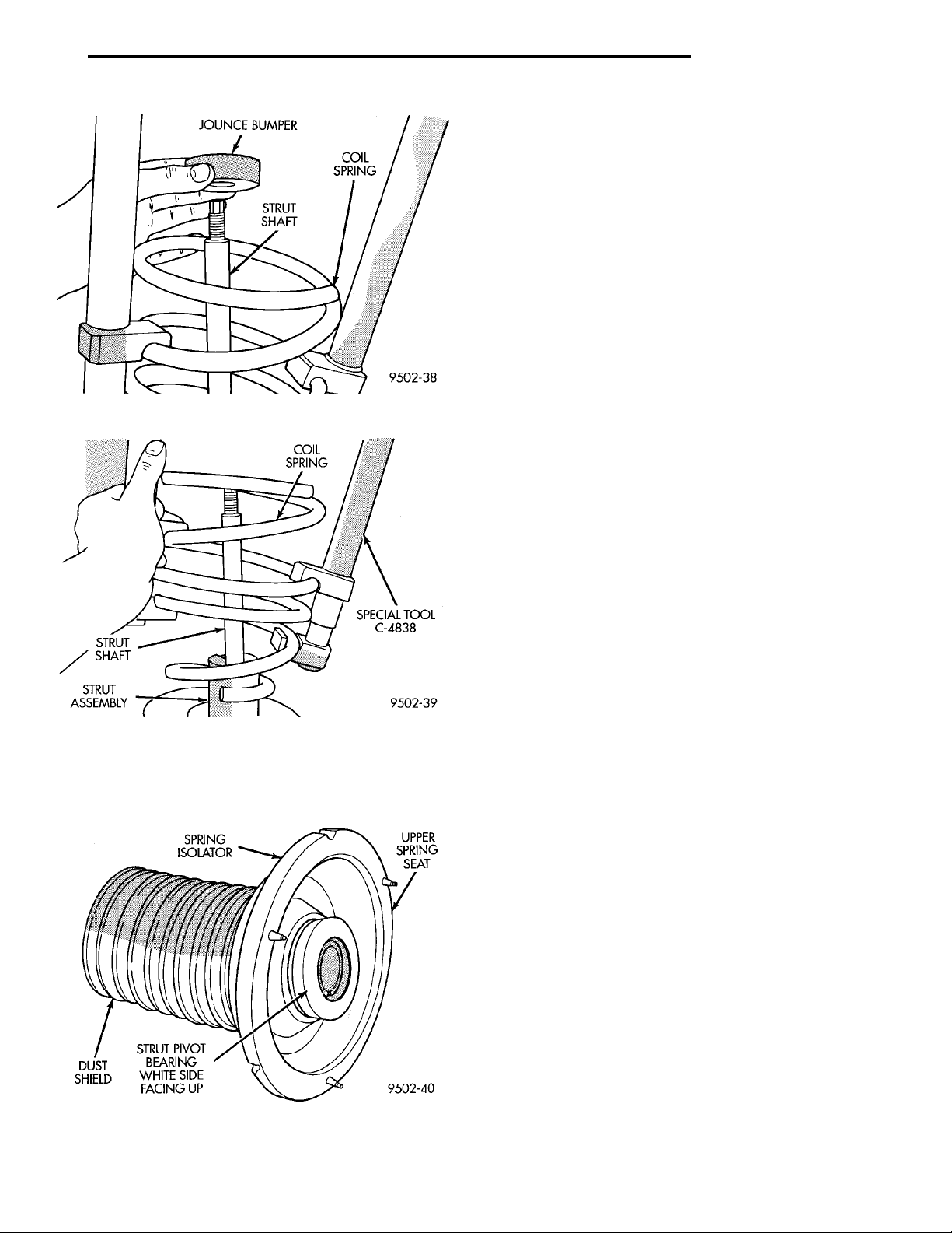
(7) Remove the jounce bumper (Fig. 64) from the
shaft of the strut assembly.
(8) Remove the coil spring from the strut assembly
(Fig. 65). Mark left and right on the coil springs
for their installation back on the correct side of
the vehicle.
WARNING: IF A REPLACEMENT COIL SPRING IS
TO BE INSTALLED ON THE STRUT ASSEMBLY, THE
FIRST FULL TOP AND BOTTOM COIL OF THE
SPRING MUST BE CAPTURED BY THE JAWS OF
THE COIL SPRING COMPRESSOR.
(9) Inspect the strut for any binding of the strut
shaft over the full stroke of the shaft.
Page 29
JOUNCE BUMPER COIL SPRINGSTRUT SHAFT
PL SUSPENSION 2 - 29
DISASSEMBLY AND ASSEMBLY (Continued)
• Mount for cracks and distortion and retaining
studs for any sign of damage.
• Severe deterioration of rubber isolator,
• Binding strut assembly pivot bearing. If pivot
SPRING ISOLATOR UPPERSPRINGSEATSTRUT PIVOTBEARING WHITESIDE FACING UPDUSTSHIELD
COIL SPRINGSPECIAL TOOLC-4838STRUT ASSEM-BLYSTRUT SHAFT
Fig. 64 Jounce Bumper Removal
bearing is replaced it is to be installed with the white
side of bearing facing up (Fig. 66).
• Inspect dust shield for rips and/or deterioration.
• Inspect jounce bumper for cracks and signs of
deterioration.
(11) Replace any components of the strut assembly
found to be worn or defective during the inspection,
before assembling the strut.
ASSEMBLE
(1) Clamp the strut assembly in a vise, with the
strut in a vertical position. When clamping the
strut assembly in the vise, do not clamp strut
using the body of the strut only by strut clevis
bracket (Fig. 59).
(2) Install the compressed coil spring onto the
strut. Coil spring is to be installed with smaller coil
down, so spring correctly seats on strut assembly
(Fig. 65).
(3) Install jounce bumper on the strut shaft (Fig.
64).
(4) Install dust shield, pivot bearing and upper
spring seat as an assembly on the strut (Fig. 63).
(5) Position upper spring seat alignment notch
with clevis bracket on strut assembly.
(6) Install strut mount on strut assembly (Fig. 62)
and the strut mount retaining nut on the shaft of the
strut assembly.
Fig. 65 Strut Assembly Coil Spring
(10) Inspect the strut mount and the upper spring
seat assembly (Fig. 66) for any of the following conditions:
Fig. 66 Upper Spring Mount And Isolator Assembly
Components
WARNING: THE FOLLOWING 2 STEPS MUST BE
COMPLETELY DONE BEFORE SPRING COMPRESSOR, SPECIAL TOOL C-4838 IS RELEASED FROM
THE COIL SPRING.
(7) Install Socket, Strut Nut, Special Tool L-4558A
(or L-4558) on the strut shaft retaining nut (Fig. 61).
Then install a 10 mm socket through the center of
the socket and on the hex of the strut shaft (Fig. 61).
While holding strut shaft from turning, torque strut
shaft retaining nut to 75 N·m (55 ft. lbs.).
(8) Equally loosen both Spring Compressors, Special Tool C-4838 until top coil of spring is fully seated
against upper spring seat and strut mount. Then
relieve all tension from spring compressors and
remove spring compressors from strut assembly
spring.
BALL JOINT
DISASSEMBLE
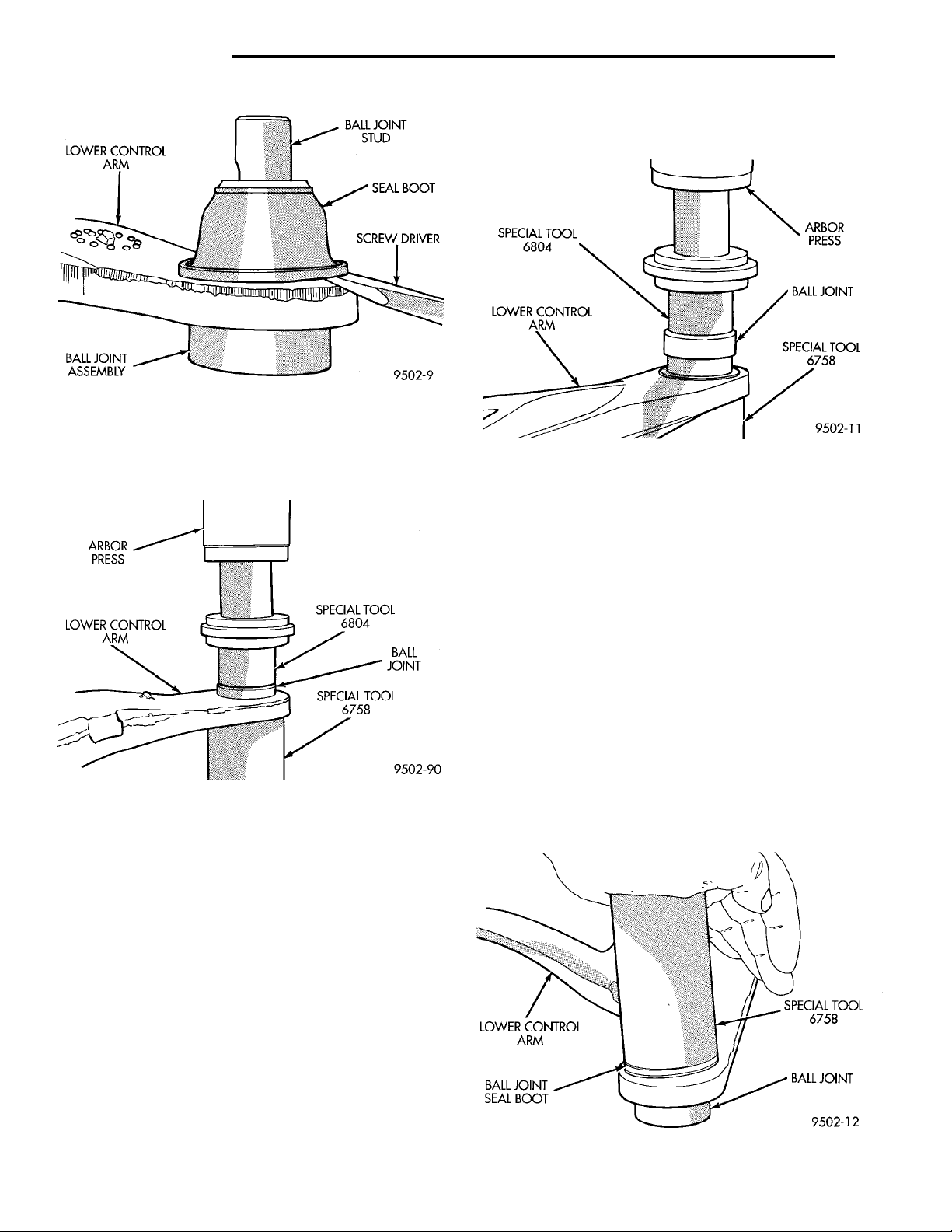
(1) Using a screw driver or other suitable tool, pry
seal boot off of ball joint assembly (Fig. 67).
Page 30
SPECIAL TOOL 6804BALL JOINTSPECIAL TOOL 6758LOWER CONTROL ARMARBOR PRESS
BALL JOINT STUDSEAL BOOTSCREWDRIVERBALL JOINTASSEMBLYLOWER CONTROL ARM
ARBOR PRESSBALL JOINTSPECIAL TOOL 6758LOWER CONTROL ARMSPECIAL TOOL 6804
2 - 30 SUSPENSION PL
DISASSEMBLY AND ASSEMBLY (Continued)
Special Tool 6804 on the bottom of the ball joint
assembly (Fig. 69).
Fig. 67 Ball Joint Seal Boot Removal
(2) Position Receiving Cup, Special Tool 6758 to
support lower control arm while receiving ball joint
assembly (Fig. 68). Install Remover/Installer, Special
Tool 6804 in top of ball joint assembly (Fig. 68).
Fig. 68 Removing Ball Joint From Lower Control Arm
(3) Using arbor press, press ball joint assembly
completely out of lower control arm.
ASSEMBLE
CAUTION: When installing ball joint in its mounting hole in lower control arm, position ball joint so
notch in ball joint stud is facing the front lower control arm bushing. This will ease assembly of ball
joint to steering knuckle when attempting to install
pinch bolt.
(1) By hand, position ball joint assembly into ball
joint bore of lower control arm. Be sure ball joint
assembly is not cocked in the bore of the control arm,
this will cause binding of the ball joint assembly,
when being pressed into lower control arm.
(2) Position assembly in an arbor press with
Receiving Cup, Special Tool 6758 supporting lower
control arm (Fig. 69). Then install Remover/Installer,
Fig. 69 Installing Ball Joint In Lower Control Arm
(3) Carefully align all pieces. Using the arbor
press apply pressure against ball joint assembly (Fig.
69), until ball joint is fully seated against bottom surface of lower control arm. Do not apply excessive
pressure against ball joint and lower control arm.
(4) Install a NEW ball joint assembly sealing boot
on ball joint assembly. Install sealing boot as far as
possible on ball joint assembly.
CAUTION: Do not use an arbor press to install the
sealing boot on the lower control arm ball joint
assembly. Damage to the sealing boot can occur do
to excessive pressure applied to sealing boot when
being installed.
(5) Position Receiving Cup, Special Tool 6758 over
sealing boot so it is aligned properly with bottom
SPECIAL TOOL 6758BALL JOINTBALL JOINT SEAL BOOTLOWER CONTROL ARM
edge of sealing boot (Fig. 70). Apply pressure BY
HAND to special tool 6758, until sealing boot is
pressed squarely against top surface of lower control
arm.
Fig. 70 Ball Joint Seal Boot Installation
Page 31
SPECIAL TOOL 6758 SPECIAL TOOL 6804VISESPECIAL TOOLC-4212–F
BUSHING IS TO BE INSTALLED IN CON-TROL ARM WITH FLANGE ON BUSHINGINSTALLED AGAINST THE RAISEDMACHINED SURFACE ON CONTROLARM AS SHOWN LOWER CONTROL ARMCONTROL ARM BUSHINGBUSHING FLANGE
LOWER CONTROL ARM SPECIAL TOOL6804BUSHINGSPECIAL TOOL C-4212–FSPECIAL TOOL 6758
SPECIAL TOOL 6810 SPECIAL TOOL C-4212–3SPECIAL TOOLC-4212–F
PL SUSPENSION 2 - 31
DISASSEMBLY AND ASSEMBLY (Continued)
LOWER CONTROL ARM FRONT ISOLATOR BUSHING
DISASSEMBLY
To perform the removal and replacement of the
lower control arm front isolator bushing, the lower
control arm must be removed from the vehicle.
(1) Remove the lower control arm assembly from
the vehicle. See Lower Control Arm in the Removal
And Installation Section in this group of the service
manual for the required removal procedure.
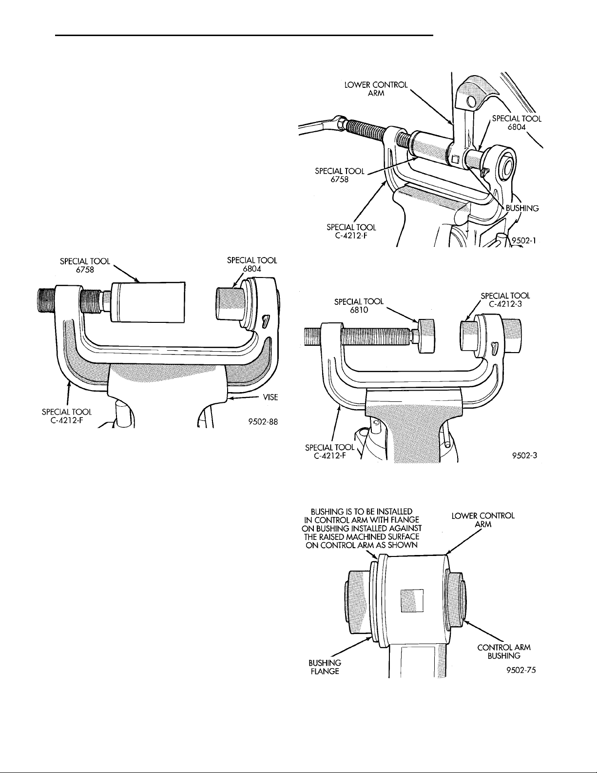
(2) Mount Remover/Installer, Special Tool
C-4212-F in a vise (Fig. 71). Install Bushing
Remover, Special Tool 6804 and Bushing Receiver,
Special Tool 6758 on Special Tool C-4212-F (Fig. 71).
Fig. 72 Removing Front Bushing From Lower
Control Arm
Fig. 71 Special Tools Assembled For Removing
Front Bushing
(3) Install lower control arm on Special Tools
assembled for removal of the front isolator bushing
as shown in (Fig. 72). Be sure Special Tool 6758 is
square on lower control arm and Special Tool 6804 is
positioned correctly on isolator bushing.
(4) Tighten screw on Remover/Installer Special
Tool C-4212-F to press front bushing out of lower
control arm.
ASSEMBLY
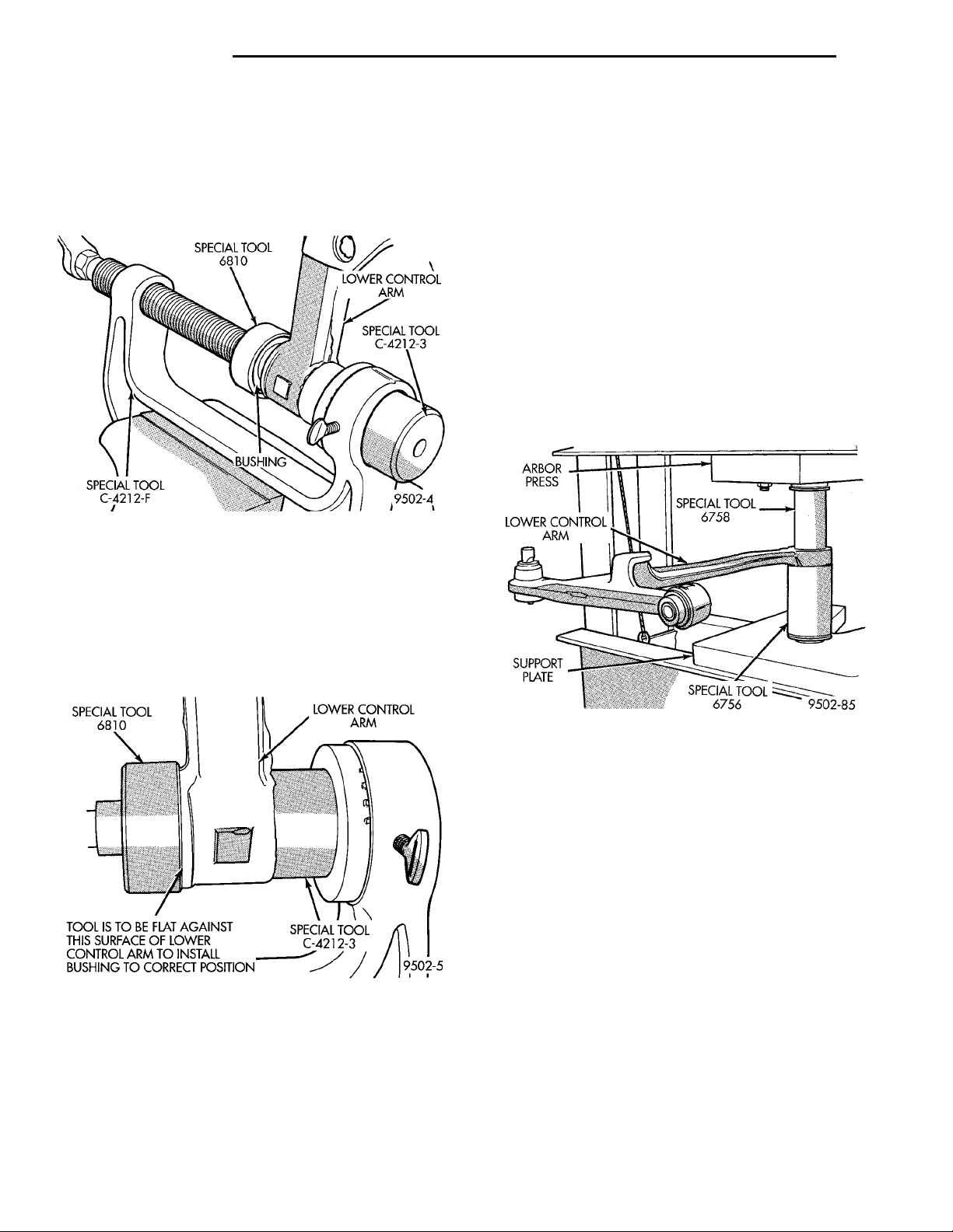
(1) Mount Installer Cup, Special Tool C-4212-F on
Remover/Installer, Special Tool C-4212-F (Fig. 73).
Then mount Bushing Installer, Special Tool 6810 on
screw portion of Remover/Installer Special Tool
C-4212-F (Fig. 73).
(2) Start front bushing into lower control arm by
hand, making sure it is square with its mounting hole in the lower control arm. Bushing is to
be installed in lower control arm from the machined
surface side of lower control arm bushing hole (Fig.
74).
Fig. 73 Special Tools Assembled For Installing
Front Bushing
Fig. 74 Installation Direction Of Lower Control Arm
Front Bushing
Page 32
SPECIAL TOOL 6810 LOWER CONTROL ARMSPECIAL TOOL C-4212–3TOOL IS TO BE FLAT AGAINST THISSURFACE OF LOWER CONTROL ARMTO INSTALL BUSHING TO CORRECTPOSITION
SPECIAL TOOL 6810 LOWER CONTROL ARMSPECIAL TOOLC-4212–3BUSHINGSPECIAL TOOL C-4212–F
ARBOR PRESS SPECIAL TOOL6758SPECIAL TOOL 6756SUPPORTPLATELOWER CONTROL ARM
2 - 32 SUSPENSION PL
DISASSEMBLY AND ASSEMBLY (Continued)
(3) Install lower control arm as shown in (Fig. 75)
on Special Tools assembled for installing front isolator bushing into lower control arm. Be sure Special
Tool C-4212-F is square on lower control arm and
Special Tool 6810 is positioned correctly on isolator
bushing.
Fig. 75 Front Bushing Installation
(4) Tighten screw on Remover/Installer Special
Tool C-4212-F pressing front bushing into lower control arm. Continue pressing front bushing into lower
control arm until special tool 6810 is sitting flush on
the machined surface of the lower control arm (Fig.
76). This will correctly position front bushing in
lower control arm.
LOWER CONTROL ARM REAR ISOLATOR BUSHING
DISASSEMBLY
Removal and installation of the lower control arm
rear isolator bushing is done using an arbor press.
Do not attempt to use a different procedure from that
below for the removal and replacement of rear lower
control arm bushing.
(1) Remove the lower control arm assembly from
the vehicle. See Lower Control Arm in the Removal
And Installation Section in this group of the service
manual for the required removal procedure.
(2) Position lower control arm in an arbor press
supported at rear bushing using Receiver Cup, Special Tool 6556 (Fig. 77). Position Remover/Installer,
Special Tool 6758 on top of rear control arm bushing
(Fig. 77).
Fig. 76 Installation Position Of Front Lower Control
Arm Bushing
(5) Install the lower control arm assembly back on
the vehicle. See Lower Control Arm in the Removal
And Installation Section in this group of the service
manual for the required installation procedure.
Fig. 77 Special Tools Assembled For Removing
Rear Bushing
(3) Press isolator bushing out of the lower control
arm.
Page 33
ARROW ON REAR BUSHINGIS TO BE POSITIONED ASINDICATED WHEN INSTALL-ING BUSHING IN LOWERCONTROL ARMCONTROL ARM BUSHINGLOWER CONTROL ARMSINGLE VOIDLOWER CONTROL ARMCOMPRESSION STRUT
ARBOR PRESS RAM REAR BUSHINGSPECIAL TOOL 6756SPECIAL TOOL6760
ARBOR PRESS SPECIAL TOOL 6760LOWER CONTROL ARMSPECIAL TOOL 6756REAR CONTROL ARM BUSHINGMUST BE FLUSH WITH CONTROLARM AT THIS LOCATION FORFULL CIRCUMFERENCE OFBUSHING
PL SUSPENSION 2 - 33
DISASSEMBLY AND ASSEMBLY (Continued)
ASSEMBLY
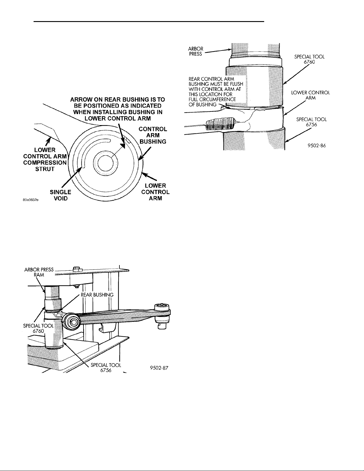
(1) Install the rear bushing into the lower control
arm in the direction indicated in (Fig. 78). Rear
bushing must be positioned in lower control
arm with the void in the bushing pointing
toward the compression strut of the lower control arm as shown in (Fig. 78).
Fig. 80 Correctly Installed Rear Bushing
SPECIFICATIONS
Fig. 78 Correct Installation Of Bushing In Lower
Control Arm
(2) Place lower control arm in an arbor press supported at rear bushing hole using Receiver Cup, Special Tool 6556 (Fig. 79). Correctly position Remover/
Installer, Special Tool 6760 on top of rear control arm
bushing (Fig. 79).
Fig. 79 Rear Bushing Installation
(3) Press rear bushing into lower control arm,
until flange on bushing is flush with machined surface of lower control arm (Fig. 80).
(4) Install the lower control arm assembly back on
the vehicle. See Lower Control Arm in the Removal
And Installation Section in this group of the service
manual for the required installation procedure.
FRONT SUSPENSION FASTENER TORQUES
DESCRIPTION TORQUE
McPHERSON STRUT:
To Shock Tower
Attaching Nuts ...........34N·m(300 in. lbs.)
Clevis Bracket To
Steering Knuckle . 54 N·m (40 ft. lbs.) + 90° Turn
Strut Shaft Nut .............74N·m(55ft.lbs.)
STEERING KNUCKLE:
Ball Joint Stud To Steering
Knuckle Nut/Bolt ..........95N·m(70ft.lbs.)
Disc Brake Caliper Bolts ......22N·m(16ft.lbs.)
STEERING GEAR:
To Crossmember Attaching
Bolts ....................68N·m(50ft.lbs.)
Tie Rod End Adjusting
Sleeve Nut ...............75N·m(55ft.lbs.)
Tie Rod End To Steering
Knuckle Nut ..............54N·m(40ft.lbs.)
FRONT SUSPENSION CROSSMEMBER:
To Body Attaching Bolts .....163N·m(120 ft. lbs.)
Lower Control Arm Pivot
Bolt ...................163N·m(120 ft. lbs.)
STABILIZER BAR:
Bushing Retainer To Crossmember
Bolts ....................28N·m(21ft.lbs.)
To Control Arm Attaching
Link Nut .................28N·m(21ft.lbs.)
HUB AND BEARING:
Front Stub Axle To Hub
Bearing Nut ............183N·m(135 ft. lbs.)
Wheel Mounting
LugNut..........109-150 N·m (80-110 ft. lbs.)
Page 34
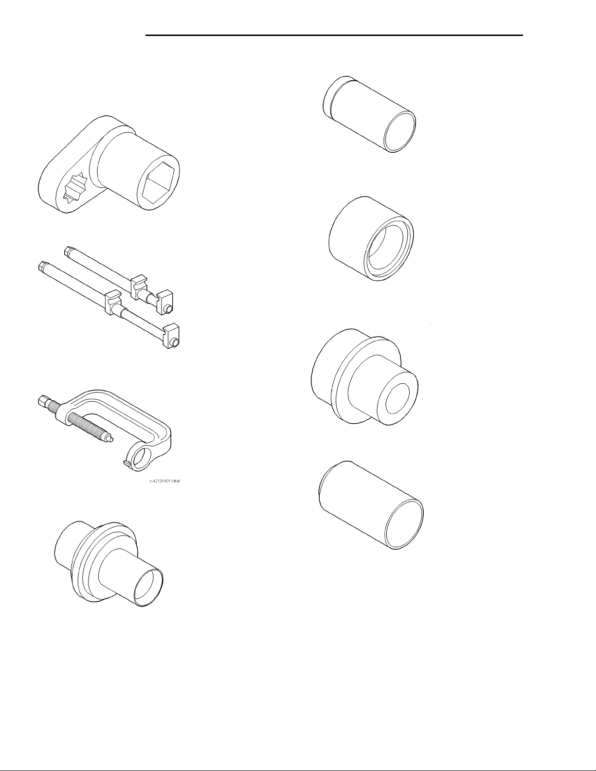
2 - 34 SUSPENSION PL
SPECIAL TOOLS
FRONT SUSPENSION
Installer Ball Joint 6758
Socket/Holder Front Strut Nut L-4558A
Installer Lower Control Arm Small Bushing 6810
Compressor Strut Coil Spring C-4838
Press Remover/Installer C-4212-F
Remover Lower Control Arm Small Bushing And
Ball Joint 6804
Adapter Ball Joint Remover/Installer C-4212-3
Receiver Ball Joint 6756
Page 35
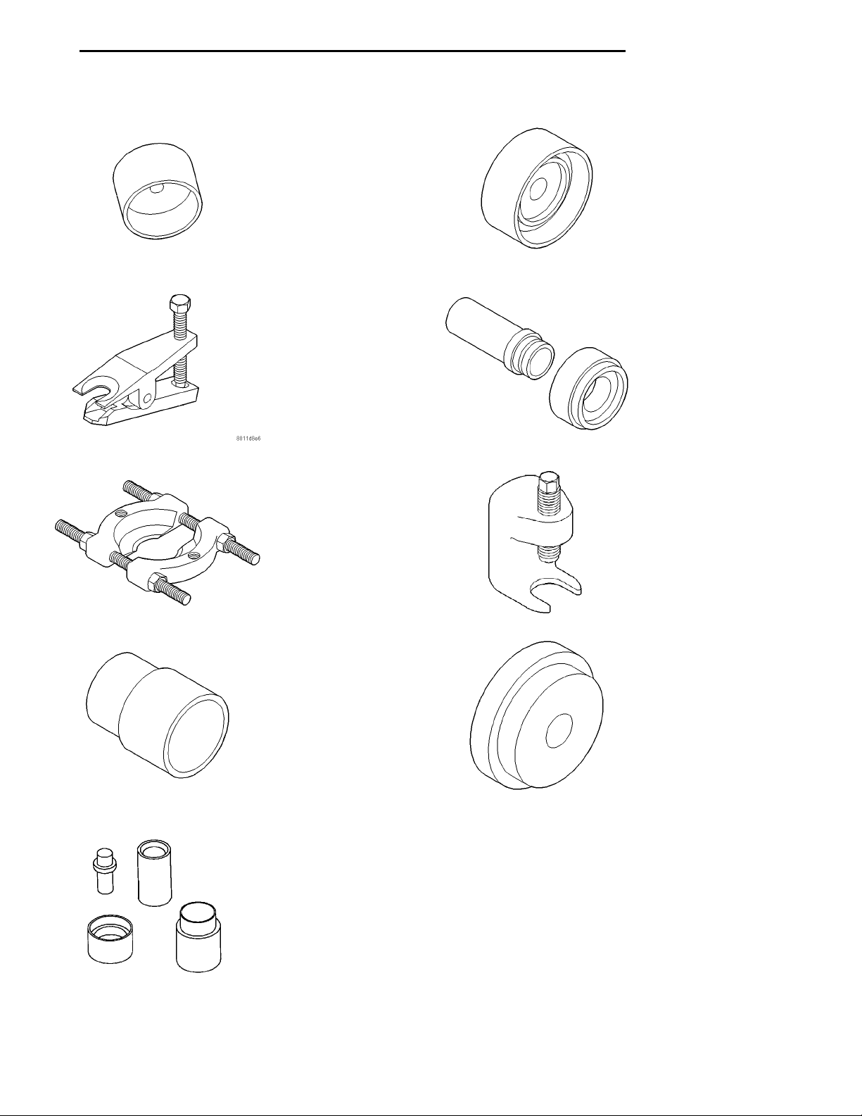
PL SUSPENSION 2 - 35
SPECIAL TOOLS (Continued)
Installer Ball Joint 6760
Remover Tie Rod End MB-990635
Puller Bearing P-334
Installer Bearing 5052
Installer Adapter C-4698-2
Remover Lower Ball Joint C-4150A
Remover Ball Joint MB-990799
Remover/Installer Lower Control Arm Bushing 6644-2
Fig. 81 Installer Bearing Cup 6522
Page 36

2 - 36 SUSPENSION PL
REAR SUSPENSION
INDEX
page page
GENERAL INFORMATION
GENERAL INFORMATION ................ 36
DESCRIPTION AND OPERATION
COIL SPRING ......................... 38
KNUCKLE ............................ 38
LATERAL LINKS AND TENSION STRUTS .... 38
REAR SUSPENSION .................... 36
STABILIZER BAR ....................... 38
STRUT ASSEMBLY ..................... 38
DIAGNOSIS AND TESTING
LATERAL LINKS ........................ 39
STABILIZER BAR AND BUSHINGS .......... 39
STABILIZER BAR ATTACHING LINKS ........ 39
STRUT INSPECTION (ON VEHICLE) ........ 38
SUSPENSION KNUCKLE ................. 39
TENSION STRUT ....................... 39
GENERAL INFORMATION
GENERAL INFORMATION
CAUTION: Only frame contact or wheel lift hoisting
equipment can be used on vehicles having a fully
independent rear suspension. Vehicles with independent rear suspension can not be hoisted using
equipment designed to lift a vehicle by the rear
axle. If this type of hoisting equipment is used damage to rear suspension components will occur.
SERVICE PROCEDURES
REAR WHEEL ALIGNMENT ............... 39
REMOVAL AND INSTALLATION
COIL SPRING ......................... 41
KNUCKLE ............................ 42
LATERAL LINKS ........................ 45
STABILIZER BAR ....................... 41
STRUT ASSEMBLY ..................... 39
DISASSEMBLY AND ASSEMBLY
STABILIZER BAR BUSHINGS .............. 49
STRUT ASSEMBLY ..................... 47
SPECIFICATIONS
REAR SUSPENSION FASTENER TORQUE
SPECIFICATIONS ..................... 50
SPECIAL TOOLS
REAR SUSPENSION .................... 50
to straighten or repair it. Always replace with a new
component.
DESCRIPTION AND OPERATION
REAR SUSPENSION
The rear suspension system used on this vehicle is
a fully independent type rear suspension system (Fig.
1).
NOTE: If a rear suspension component becomes
bent, damaged or fails, no attempt should be made
Page 37
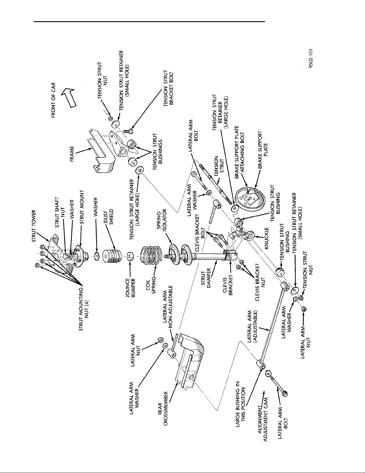
PL SUSPENSION 2 - 37
DESCRIPTION AND OPERATION (Continued)
Fig. 1 Neon Fully Independent Rear Suspension
Page 38
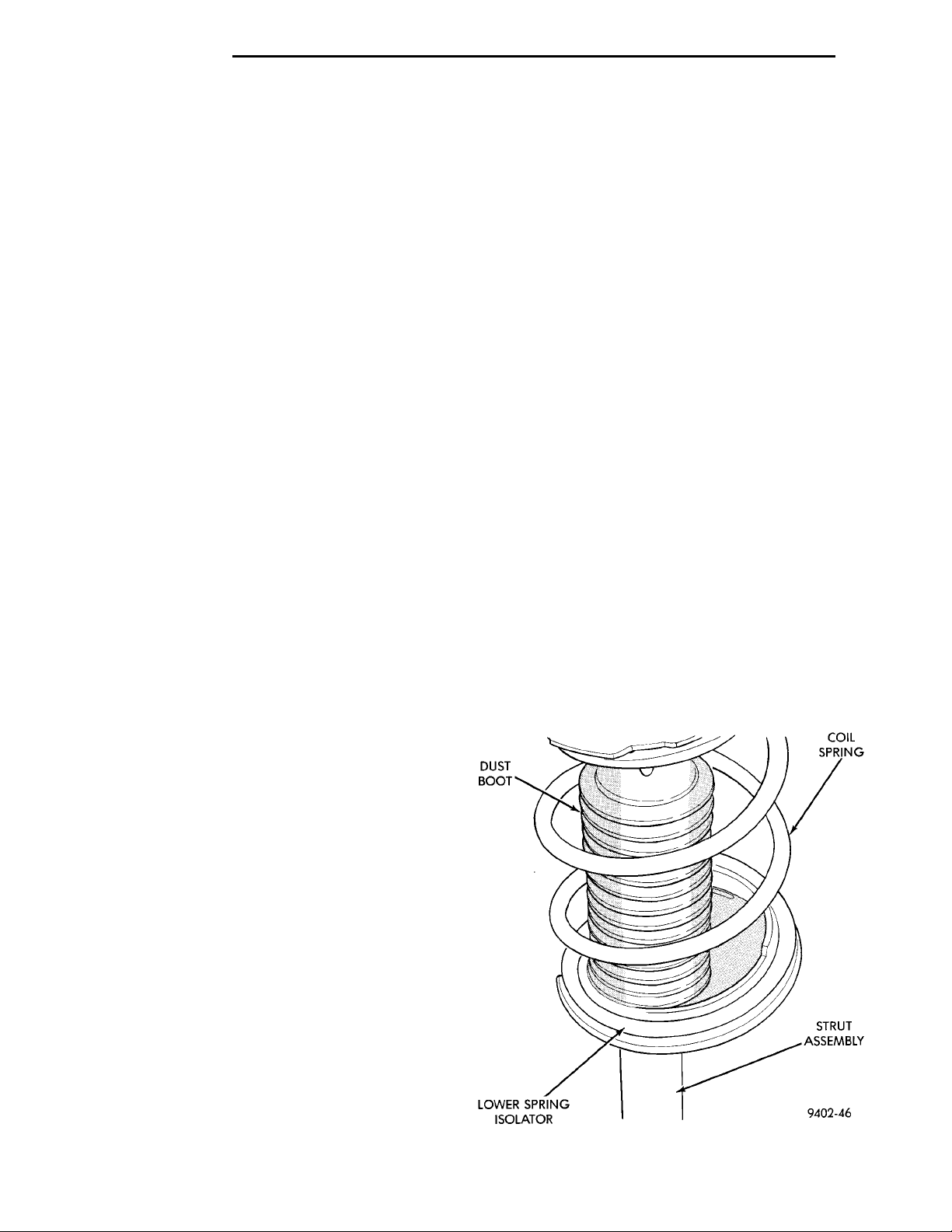
DUST BOOT COIL SPRINGLOWER SPRING ISOLATOR STRUT ASSEMBLY
2 - 38 SUSPENSION PL
DESCRIPTION AND OPERATION (Continued)
STRUT ASSEMBLY
The rear strut assemblies support the weight of
the vehicle using coil springs positioned around the
struts. The coil springs are contained between the
upper mount of the strut assembly and a lower
spring seat on the body of the strut assembly.
The top of each strut assembly is bolted to the top
of the inner fender through a rubber isolated mount.
The bottom of the strut assembly attaches to the
rear knuckle using 2 thru-bolts and prevailing torque
nuts. Rear Caster and camber on this vehicle is a
fixed setting (net build) and is not required to be
adjusfted as a normal procedure when performing an
alignment on this vehicle.
COIL SPRING
Rear coil springs are rated separately for each corner or side of the vehicle depending on optional
equipment and type of vehicle service. During service
procedures when both rear coil springs are removed,
mark the coil springs to ensure installation of the
springs in their original position. If coil springs
require replacement, be sure the springs needing replacement, are replaced with springs
meeting the correct load rating for the vehicle
and its specific options.
STABILIZER BAR
The stabilizer bar interconnects both rear strut
assemblies and is attached to the rear frame rails of
the vehicle.
Jounce and rebound movements affecting one
wheel are partially transmitted to the opposite wheel
of the vehicle to stabilize body roll.
Attachment of the stabilizer bar to the rear frame
rails of the vehicle is through 2 rubber-isolator bushings and bushing retainers. The stabilizer bar to
strut assembly attachment is done utilizing a rubber
isolated stabilizer bar attaching link. All parts of the
stabilizer bar are serviceable, and the stabilizer bar
to frame rail isolator bushings are split for easy
removal and installation. The split in the stabilizer
bar to crossmember bushing must be positioned
toward the rear of the vehicle, when the stabilizer
bar is installed on the vehicle.
LATERAL LINKS AND TENSION STRUTS
The lateral arms and tension strut have rubber
isolator bushings at each end. The lateral arms are
attached to the rear crossmember and knuckle, using
a unique bolt and nut assembly at each end. The lateral arm to rear crossmember attaching bolts are
longer than the lateral arm to knuckle attaching
bolts. Each lateral arm to knuckle attaching bolt and
nut assembly uses 2 flat washers. Each lateral arm
to rear crossmember attaching bolt uses 1 flat
washer and 1 adjustment cam to provide a means for
rear wheel Toe adjustment. The tension strut assembly attaches to a bracket on the frame rail and to the
bottom of the knuckle.
Lateral arms, tension struts and knuckles are normally replaced only when the part has been damaged
or when the vehicle has been involved in an accident.
If a suspension part has been damaged, be sure to
check the underbody dimensions of the car. If underbody dimensions of the vehicle are not correct, the
frame must be straightened before replacement suspension components are installed.
DIAGNOSIS AND TESTING
STRUT INSPECTION (ON VEHICLE)
(1) Inspect for damaged or broken coil springs
(Fig. 2).
(2) Inspect for torn or damaged strut assembly
dust boots (Fig. 2).
(3) Inspect for damaged lower spring isolator (Fig.
2).
KNUCKLE
A forged rear knuckle bolts to each rear strut
assembly. The movement of the rear knuckle is controlled laterally using two lateral arms attached to
the knuckle. The outboard ends of the two lateral
arms are mounted forward and rearward of the spindle centerline, and inboard ends are mounted to the
rear crossmember. Fore and aft movement of the
knuckle is controlled by using a tension strut.
Fig. 2 On Vehicle Strut Assembly Inspection
Page 39
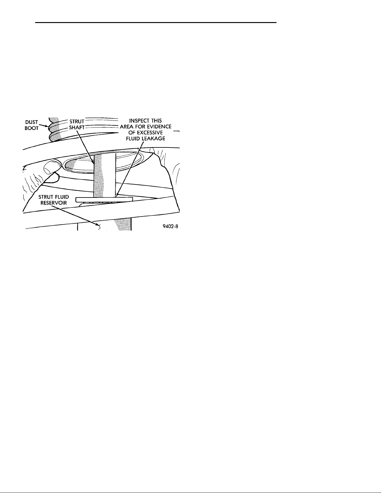
DUSTBOOT STRUTSHAFTSTRUT FLUIDRESERVOIR INSPECT THIS AREA FOREVIDENCE OF EXCESSIVEFLUID LEAKAGE
PL SUSPENSION 2 - 39
DIAGNOSIS AND TESTING (Continued)
(4) Lift dust boot and inspect strut assembly for
evidence of fluid running from the upper end of fluid
reservoir. (Actual leakage will be a stream of fluid
running down the side and dripping off lower end of
unit). A slight amount of seepage between the strut
rod and strut shaft seal is not unusual and does not
affect performance of the strut assembly (Fig. 3). Also
inspect jounce bumpers for signs of damage or deterioration.
Fig. 3 Strut Assembly Leakage Inspection
and or the retainers will be required. The bushings
and retainers are serviceable as separate components
of the tension strut.
Inspect the tension strut for signs of contact with
the ground or road debris which has bent or caused
other damage to the tension strut. If the tension
strut is bent or damaged the tension strut will
require replacement. Do not attempt to repair or
straighten a tension strut.
STABILIZER BAR AND BUSHINGS
Inspect the stabilizer bar for damage or bending.
Inspect for broken or distorted stabilizer bar bushings, bushing retainers, and worn or damaged stabilizer bar to strut attaching links. If stabiizer bar to
rear frame rail bushing replacement is required,
bushings can be removed from sway bar by opening
slit and peeling bushing off sway bar.
STABILIZER BAR ATTACHING LINKS
Inspect the bushings and sleeves in the stabilizer
bar attaching links for damage or deterioration.
Inspect the stabilizer bar attaching link to ensure it
is not bent or broken. If any of these conditions are
present when inspecting the attaching links, replacement of the attaching link is required.
SUSPENSION KNUCKLE
The rear suspension knuckle is not a repairable
component of the rear suspension. If it is determined
that the knuckle is broken or bent when servicing
the vehicle, no attempt is to be made to repair or to
straighten the knuckle. THE KNUCKLE MUST BE
REPLACED IF FOUND TO BE DAMAGED IN
ANY WAY.
LATERAL LINKS
Inspect the lateral link isolator bushings and
sleeves for signs of damage or deterioration. If the
lateral link isolator bushings or sleeves are damaged
or are deteriorated, replacement of the lateral link
assembly will be required. The isolator bushings are
not serviceable as a separate component of the lateral link assembly.
Inspect the lateral links for signs of contact with
the ground or road debris which has bent or caused
other damage to the lateral link assembly. If the lateral link is bent or damaged, the lateral link will
require replacement. Do not attempt to repair or
straighten a lateral link.
TENSION STRUT
Inspect the tension strut bushings and retainers
for signs of deterioration or damage. If the tension
strut bushings are deteriorated or the retainers are
damaged, replacement of the tension strut bushings
SERVICE PROCEDURES
REAR WHEEL ALIGNMENT
Refer to Front And Rear Wheel Toe Setting Procedures in the Wheel Alignment Check And Adjustment
section in this group of the service manual for the
required rear wheel Toe setting procedure.
REMOVAL AND INSTALLATION
STRUT ASSEMBLY
REMOVE
(1) Raise vehicle on jackstands or centered on a
frame contact type hoist. See Hoisting in the Lubrication and Maintenance section of this manual, for
the required lifting procedure to be used for this
vehicle.
(2) Remove the rear wheel and tire assembly from
the vehicle.
(3) Remove hydraulic flex hose bracket, from
bracket on rear strut assembly (Fig. 4). If vehicle is
equipped with Anti-Lock brakes, the wheel speed
sensor cable routing clip is also attached to the strut
assembly bracket.
(4) Support rear knuckle, suspension and brake
components of vehicle before removing clevis bracket
to knuckle attaching bolts. Do not let weight of
Page 40
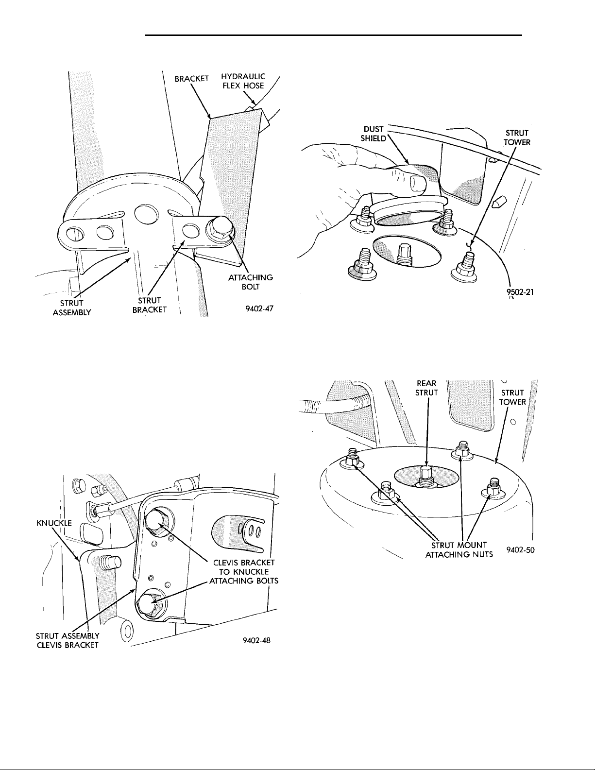
KNUCKLESTRUT ASSEMBLY CLEVISBRACKET CLEVIS BRACKET TOKNUCKLE ATTACHINGBOLTS
BRACKET HYDRAULICFLEX HOSESTRUT ASSEM-BLY STRUT BRACKET ATTACHING BOLT
DUST SHIELD STRUT TOWER
REAR STRUT
STRUTTOWERSTRUT MOUNT ATTACHINGNUTS
2 - 40 SUSPENSION PL
REMOVAL AND INSTALLATION (Continued)
(7) Remove carpet (if required) from top of strut
tower. Then remove rubber dust shield (Fig. 6) from
top of strut tower, this will allow easier access to
upper strut mount attaching nuts.
Fig. 4 Hydraulic Flex Hose Bracket Attachment To
Strut
rear knuckle and assembled components hang
unsupported when strut is removed.
CAUTION: The knuckle to strut assembly attaching
bolts are serrated and must not be turned during
removal. Remove nuts while holding bolts stationary in knuckle.
(5) Remove the 2 clevis bracket bolts (Fig. 5)
attaching strut assembly to rear knuckle.
Fig. 6 Dust Shield Removal From Strut Tower
(8) Loosen but do not remove the 4 upper strut
mount to strut tower attaching nuts (Fig. 7). Then
while supporting the strut assembly fully remove the
4 strut mount attaching nuts.
Fig. 7 Strut Mount Attaching Nuts
(9) Remove strut assembly from knuckle, by sliding knuckle out of clevis bracket on strut assembly.
Then remove strut assembly from vehicle.
Fig. 5 Knuckle To Clevis Bracket Bolts
(6) Lower vehicle. Access to rear upper strut
mount to strut tower attaching bolts, is through the
trunk of the vehicle.
INSTALL
(1) Position strut assembly back into vehicle with
the 4 studs on strut mount assembly through holes
in strut tower of vehicle. Install the 4 strut mount to
body attaching nuts (Fig. 7) onto mount studs.
Torque the 4 strut mount to body attaching nuts to
34 N·m (300 in. lbs).
Page 41
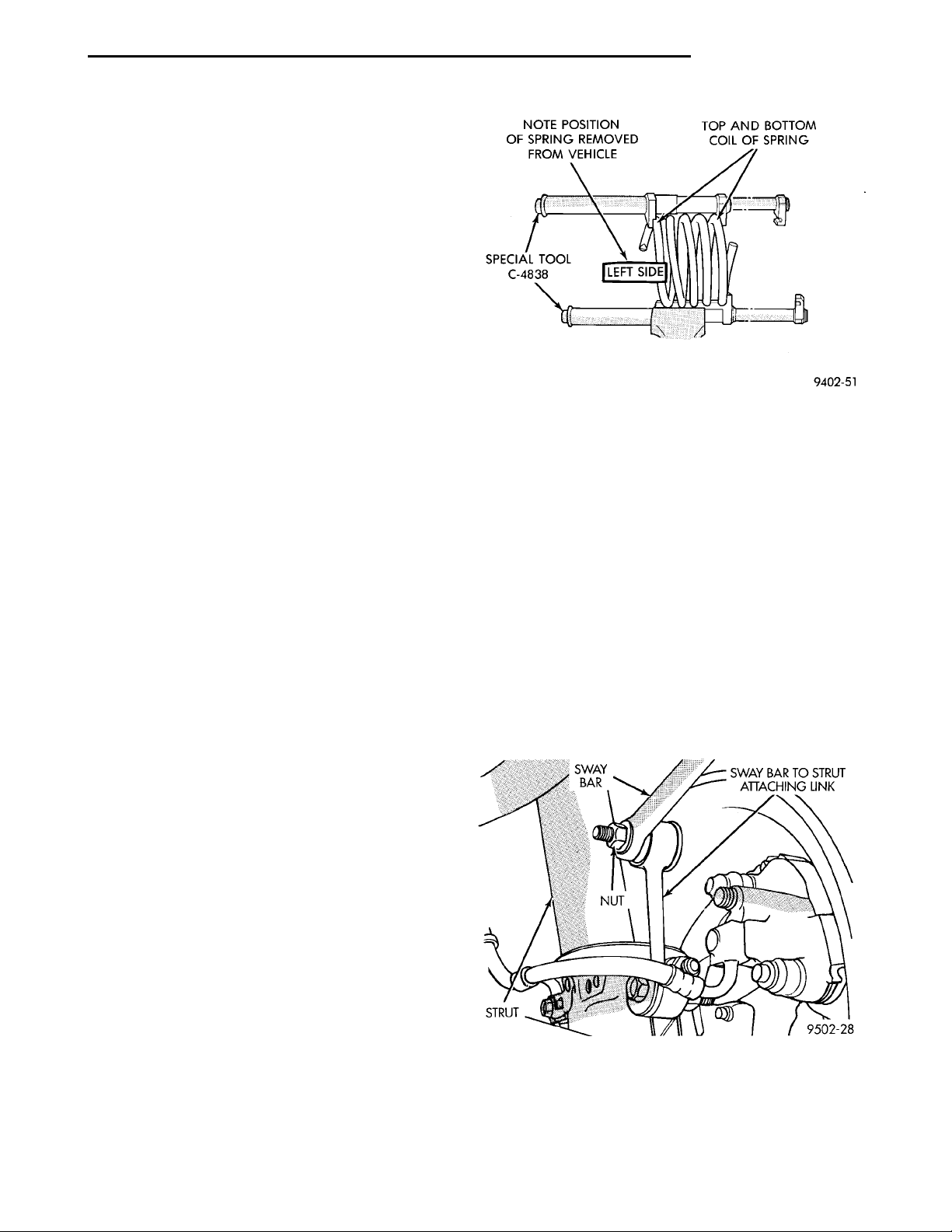
NOTE POSITION OF SPRINGREMOVED FROM VEHICLESPECIAL TOOL C-4838
SWAY BAR SWAY BAR TO STRUTATTACHING LINKNUTSTRUT
LEFT SIDE
TOP AND BOTTOM COIL OFSPRING
PL SUSPENSION 2 - 41
REMOVAL AND INSTALLATION (Continued)
(2) Install dust shield into hole on top of strut
tower (Fig. 6). Install carpeting back on top of rear
strut tower.
(3) Raise vehicle.
CAUTION: The knuckle to strut assembly attaching
bolts are serrated and must not be turned during
installation. Install and torque nuts while holding
bolts stationary in knuckle.
(4) Install knuckle assembly into clevis bracket on
strut assembly. Install the 2 clevis bracket to knuckle
assembly attaching bolts and nuts (Fig. 5). Torque
both clevis bracket to knuckle assembly attaching
nuts to 95 N·m (70 ft. lbs.).
(5) Install hydraulic flex hose bracket, on strut
assembly bracket (Fig. 4). Install and securely
tighten bolt attaching hose bracket to strut bracket.
If vehicle is equipped with Anti-Lock brakes, the
wheel speed sensor cable routing clip is also attached
to the strut assembly bracket.
(6) Install wheel and tire assembly on vehicle.
Tighten the wheel mounting stud nuts in proper
sequence until all nuts are torqued to half specification. Then repeat tightening sequence to full specified torque of 135 N·m (100 ft. lbs.).
(7) Lower vehicle to the ground.
(8) Check and reset rear wheel TOE to specifications if required. Refer to Front And Rear Toe Setting
Procedure in the Wheel Alignment Check And
Adjustment section in this group of the service manual for the required Toe setting procedure.
COIL SPRING
Coil springs are rated separately for each side of
vehicle depending on optional equipment and type of
service. During service procedures where both
springs are removed, mark springs (Chalk, Tape,
etc.) (Fig. 8) to ensure installation in original position. If the coils springs require replacement. Be
sure that the springs needing replacement, are
replaced with springs meeting the correct load
and spring rate for the vehicle.
strut assembly in the disassembly and assembly section in this group of the service manual for the
required procedure to disassemble and assemble the
strut assembly for the removal of the coil spring.
STABILIZER BAR
REMOVE
(1) Raise vehicle on jackstands or centered on a
frame contact type hoist. See Hoisting in the Lubrication and Maintenance section of this manual, for
the required lifting procedure to be used for this
vehicle.
(2) Remove both rear wheel and tire assemblies
from the vehicle.
(3) Remove rear stabilizer bar from the 2 stabilizer
bar to strut attaching links (Fig. 9).
Fig. 8 Identifying Coil Springs
NOTE: During service procedures requiring
removal or installation of a coil spring with Spring
Compressor, Special Tool C-4838. It is required that
the first full top and bottom coil of the coil spring
be captured by the jaws of spring compressor (Fig.
8).
Replacement of the coil spring requires removal of
the strut assembly from the vehicle, and the disassembly of the strut. Refer to strut assembly in the
removal and installation section in this group of the
service manual for the required removal and replacement procedure for the strut assembly. Then refer to
Fig. 9 Sway Bar To Strut Attaching Link
(4) Rotate stabilizer bar down slightly to clear
attaching links.
(5) Remove the 2 stabilizer bar to rear frame rail
retainers (Fig. 10).
Page 42
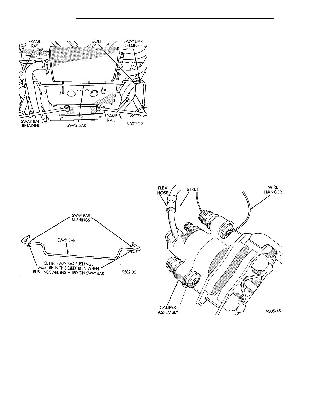
FRAME RAIL BOLT SWAY BARRETAINERFRAMERAILSWAY BARSWAY BARRETAINER
SWAY BARBUSHINGSSWAY BARSLIT IN SWAY BAR BUSHINGS MUST BEIN THIS DIRECTION WHEN BUSHINGSARE INSTALLED ON SWAY BAR
FLEXHOSE STRUT WIRE HANGERCALIPERASSEMBLY
2 - 42 SUSPENSION PL
REMOVAL AND INSTALLATION (Continued)
sequence until all nuts are torqued to half specification. Then repeat the tightening sequence to the full
specified torque of 129 N·m (95 ft. lbs.).
(5) Lower the vehicle to the ground.
(6) With suspension supporting the full weight of
the vehicle, securely tighten the stabilizer bar
retainer to frame rail attaching bolts (Fig. 9).
KNUCKLE
REMOVE
(1) Raise vehicle on jackstands or centered on a
frame contact type hoist. See Hoisting in the Lubrication and Maintenance section of this manual, for
the required lifting procedure to be used for this
vehicle.
Fig. 10 Sway Bar To Frame Rail Retainers
(6) Remove stabilizer bar from vehicle.
STABILIZER BAR AND BUSHING INSPECTION
Inspect for broken or distorted retainers and bushings. If bushing replacement is required, bushing can
be removed by opening slit in bushing and removing
bushing from around stabilizer bar. When bushings
are installed on stabilizer bar, bushings must be
installed with slit positioned on stabilizer bar so slit
will face rear of vehicle when stabilizer bar is
installed (Fig. 11).
(2) Remove the rear wheel and tire.
(3) If vehicle is equipped with rear disc brakes,
remove the rear caliper from the adapter. Refer to
Rear Disk Brakes in Group 5 Brakes of this Service
manual for required caliper removal procedure. After
removing the caliper, store the caliper by hanging it
from frame of the vehicle (Fig. 12). Do not let weight
of rear caliper hang from flexible brake hose.
Fig. 11 Bushings Correctly Installed On Stabilizer
Bar
INSTALL
(1) Install stabilizer bar and isolator bushings
back into the vehicle as an assembly. Position stabilizer bar so it is centered in the vehicle and does not
contact other suspension components or vehicle body.
(2) Install the 2 stabilizer bar to frame rail retainers into frame rail and loosely install both retainer
attaching bolts (Fig. 10).
(3) Position both stabilizer bar to strut assembly
attaching links on stabilizer bar. Install and securely
tighten the stabilizer bar attaching link to stabilizer
bar attaching nuts (Fig. 9).
(4) Install wheel and tire assembly on vehicle.
Tighten the wheel mounting stud nuts in proper
Fig. 12 Storing Rear Caliper
(4) If vehicle is equipped with rear disc brakes,
remove rotor from hub. If vehicle is equipped with
rear drum brakes, remove brake drum from hub.
(5) If vehicle is equipped with ABS brakes, remove
the speed sensor head from the rear disc brake
adapter (Fig. 13).
Page 43
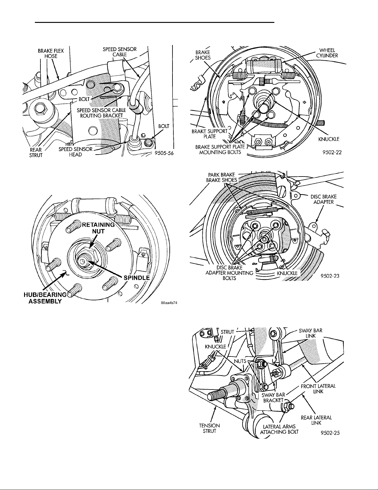
BRACKET
BRAKE SHOES WHEEL CYL-INDERKNUCKLEBRAKE SUPPORT PLATEMOUNTING BOLTSBRAKE SUPPORTPLATE
PARK BRAKE BRAKESHOES DISC BRAKEADAPTERKNUCKLEDISC BRAKE ADAPTERMOUNTING BOLTS
PL SUSPENSION 2 - 43
REMOVAL AND INSTALLATION (Continued)
Fig. 13 Speed Sensor Head Attachment To Disc
Brake Adapter
(6) Remove rear hub/bearing retaining nut (Fig.
14). Then remove the hub/bearing from the knuckle.
Fig. 14 Hub/ Bearing Retaining Nut
(7) If vehicle is equipped with rear drum brakes
remove the 4 bolts (Fig. 15) attaching rear brake support plate to knuckle. Then remove brake support
plate, brake shoes and wheel cylinder as an assembly
from rear knuckle (Fig. 15). It is not necessary to
remove brake flex hose from wheel cylinder
when removing support plate. Brake support
plate when removed, must be supported in same
manner as caliper assembly.
(8) On vehicles equipped with rear disc brakes,
remove the 4 bolts attaching disc brake adapter to
rear knuckle (Fig. 16). Then remove the adapter,
rotor shield, park brake shoes and park brake cable
as an assembly from knuckle.
CAUTION: The knuckle to strut assembly attaching
bolts are serrated and must not be turned during
removal. Loosen and remove nuts while holding
bolts stationary in knuckle.
Fig. 15 Drum Brake Support Plate Mounting Bolts
Fig. 16 Disc Brake Adapter Mounting
(9) Loosen but do not remove at this time, the 2
strut assembly to knuckle attaching bolts (Fig. 17).
Then remove the lateral links to knuckle attaching
bolt (Fig. 17).
Fig. 17 Knuckle To Strut And Lateral Arm Mounting
Bolts
Page 44
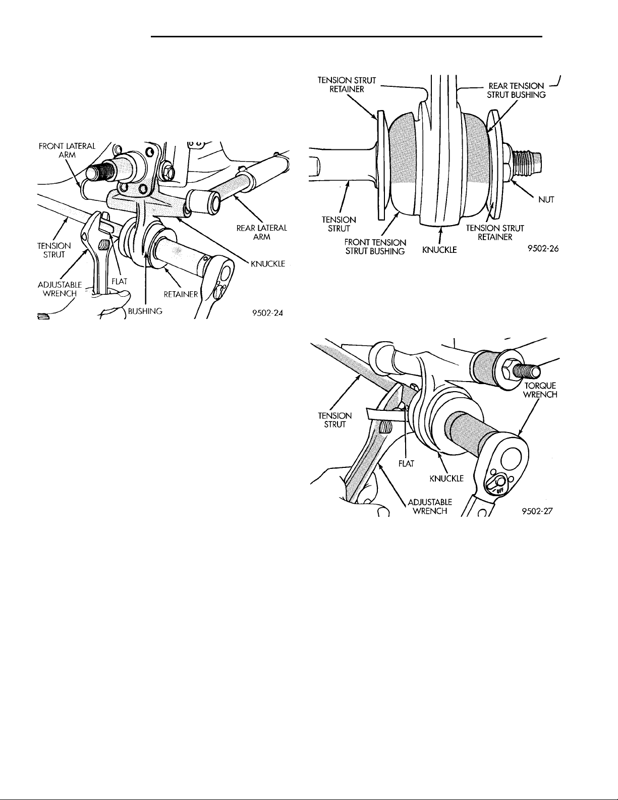
FRONT LATERAL ARM REAR LATERAL ARMKNUCKLERETAINERBUSHINGFLATADJUSTABLEWRENCHTENSIONSTRUT
TENSION STRUTRETAINER REAR TENSIONSTRUT BUSHING NUTTENSION STRUTRETAINERKNUCKLEFRONT TENSION STRUTBUSHINGTENSION STRUT
KNUCKLEFLATADJUSTABLEWRENCHTENSION STRUT
TORQUE
WRENCH
2 - 44 SUSPENSION PL
REMOVAL AND INSTALLATION (Continued)
(10) Hold tension strut from turning by using a
large adjustable wrench on flat of tension strut (Fig.
18) and remove tension strut nut. Then remove nut,
tension strut retainer and rear tension strut bushing
from tension strut at rear knuckle (Fig. 18).
Fig. 19 Tension Strut Bushings Installed On Tension
Strut
(5) Position a large adjustable wrench on flat of
tension strut to keep it from turning, (Fig. 20) and
then torque tension strut nut to 95 N·m (70 ft. lbs.).
Fig. 18 Tension Strut To Rear Knuckle Attachment
(11) Remove both rear knuckle to strut assembly
clevis bracket attaching bolts (Fig. 17). If vehicle is
equipped with a rear sway bar also remove the sway
bar link to strut mounting bracket (Fig. 17).
(12) Remove knuckle assembly from strut, by sliding knuckle straight out of clevis bracket on strut
assembly. Then remove knuckle from tension strut.
INSTALL
(1) Insert tension strut, tension strut bushing and
tension strut retainer into knuckle. Then install
knuckle into clevis bracket on rear strut assembly.
Be sure stepped area of bushing is squarely
seated into hole in knuckle.
CAUTION: The knuckle to strut assembly attaching
bolts are serrated and must not be turned during
installation. Tighten and torque nuts while holding
bolts stationary in knuckle.
(2) Install the 2 strut assembly clevis bracket to
knuckle attaching bolts and nuts (Fig. 17). Torque
the attaching bolts to 95 N·m (70 ft. lbs.).
(3) Install the lateral arms to knuckle attaching
bolt, washers and nut as shown in (Fig. 17). Do not
tighten the lateral link bolt at this time. The
vehicle must be at curb height when tightening
the lateral link bolts.
(4) Install tension strut bushing, tension strut
retainer and nut on tension strut (Fig. 19). When
installing tension strut retainers, the retainers
must be installed on tension strut, with cupped
side of retainer facing away from bushing and
knuckle (Fig. 19).
Fig. 20 Torquing Tension Strut Nut
(6) On vehicles equipped with rear drum brakes,
install rear brake support plate assembly onto the
knuckle (Fig. 15). Install the 4 bolts (Fig. 15) attaching rear brake support plate to rear knuckle. Torque
attaching bolts to 68 N·m (50 ft. lbs.).
(7) On vehicles equipped with rear disc brakes,
install the disc brake adapter on knuckle (Fig. 16)
Install the 4 bolts attaching the disc brake adapter to
knuckle (Fig. 16). Torque attaching bolts to 68 N·m
(50 ft. lbs.).
(8) If vehicle is equipped with ABS brakes, install
speed sensor head into rear brake support plate or
disc brake adapter or (Fig. 13). Torque speed sensor
head mounting bolt to 7 N·m (60 in. lbs.).
Page 45
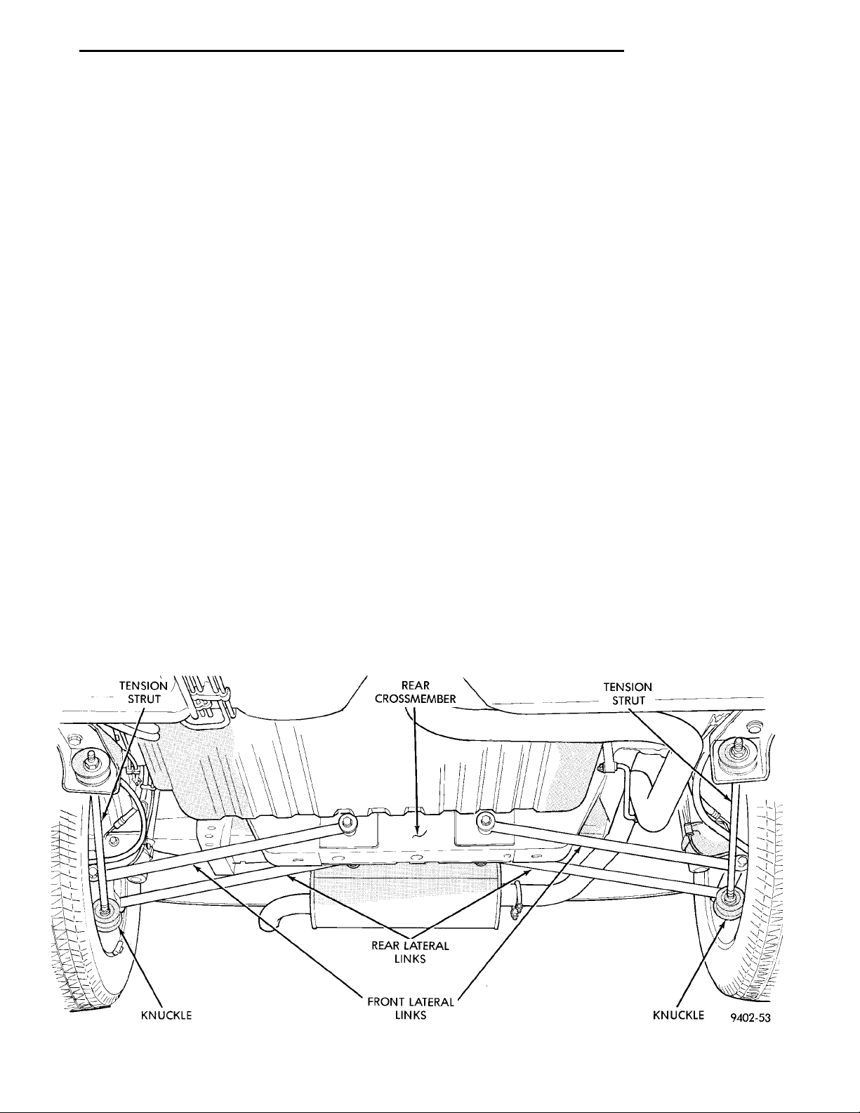
TENSION STRUT REAR CROSSMEMBER TENSIONSTRUTREAR LATERAL LINKSFRONT LATERAL LINKS KNUCKLEKNUCKLE
PL SUSPENSION 2 - 45
REMOVAL AND INSTALLATION (Continued)
CAUTION: The hub/bearing retaining nut must be
tightened to but must not exceed its required
torque specification. The proper torque specification of the retaining nut is critical to the life of the
hub bearing.
(9) Install rear hub and bearing assembly on
knuckle. Install hub and bearing assembly retaining
nut (Fig. 14), and torque to 217 N·m (160 ft. lbs).
(10) If vehicle is equipped with rear disc brakes,
install rear braking disc on hub. If vehicle is
equipped with rear drum brakes, install the brake
drum on hub.
(11) If vehicle is equipped with rear disc brakes,
install rear braking disc on hub. Carefully install
rear brake caliper over braking disc and install on
adapter. Tighten the caliper assembly to adapter
mounting bolts to 22 N·m (192 in. lbs.). Refer to Rear
Disc Brakes in Group 5 Brakes in this service manual for required caliper installation procedure.
(12) Install wheel and tire assembly on vehicle.
Tighten the wheel mounting stud nuts in proper
sequence until all nuts are torqued to half specification. Then repeat the tightening sequence to the full
specified torque of 135 N·m (100 ft. lbs.).
(13) Lower vehicle.
(14) With suspension supporting total weight of
vehicle, and lateral links at correct curb height,
torque both lateral link attaching bolts to 95 N·m (70
ft. lbs.).
(15) Check and reset rear wheel TOE to specifications if required. Refer to Front And Rear Toe Setting
Procedure in the Wheel Alignment Check And
Adjustment section in this group of the service manual for the required Toe setting procedure.
LATERAL LINKS
The rear suspension lateral links (Fig. 21) are only
serviced as complete assemblies. The isolator bushings used in the lateral links are not serviced as separate components. The rear lateral link assemblies
are unique, having different size bushings to accommodate the rear Toe adjustment cams. The rearward
lateral links, must be installed with small bushing
sleeve at knuckle and large bushing sleeve at rear
crossmember. This is required to accommodate the
rear Toe adjustment cam.
REMOVE
(1) Raise vehicle on jackstands or centered on a
frame contact type hoist. See Hoisting in the Lubrication and Maintenance section of this manual, for
the required lifting procedure to be used for this
vehicle.
(2) Remove the rear wheel and tire assembly from
the side of the vehicle requiring lateral link removal.
(3) Remove the nut, bolt and washers attaching
the lateral links to the knuckle (Fig. 22).
(4) Remove nut, bolt, washer and Toe adjustment
cam, attaching lateral links requiring removal, from
rear crossmember (Fig. 23). Then remove lateral
links from vehicle.
INSTALL
Rear lateral links when being installed, must be
specifically positioned and orientated on the vehicle.
Fig. 21 Rear Suspension Lateral Links
Page 46
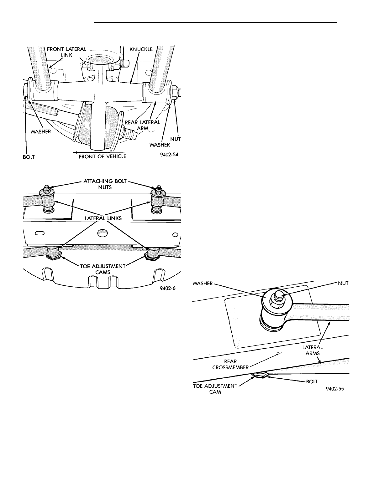
2 - 46 SUSPENSION PL
REMOVAL AND INSTALLATION (Continued)
(1) Install washer on short lateral link attaching
bolt. Then install short lateral link attaching bolt,
into lateral link having the same size bushing
sleeves. Then install lateral link, bolt and washer
onto knuckle as an assembly, with head of bolt facing
to front of vehicle (Fig. 22).
(2) Install lateral link with small and large bushing sleeve, on lateral link attaching bolt in rear
knuckle (Fig. 22). Small bushing sleeve must be
installed on bolt in rear knuckle with large
bushing sleeve at crossmember of vehicle.
(3) Install washer and nut onto lateral link attaching bolt at rear knuckle (Fig. 22). Do not tighten
the lateral link to rear knuckle attaching bolt
at this time.
(4) Install Toe adjustment cam on long lateral link
Fig. 22 Lateral Link Attachment To Knuckle
attaching bolt. Install long lateral link attaching bolt
and adjustment cam, into lateral link toward rear of
vehicle, having the large bushing sleeve. Then pass
lateral link attaching bolt into rear crossmember
(Fig. 24). Head of long lateral link to crossmem-
ber attaching bolt must face to rear of vehicle
when installed.
(5) Position forward rear lateral link against rear
crossmember (Fig. 24). Then pass the lateral link
attaching bolt through front lateral link bushing
WASHER
sleeve.
LATERAL ARMSBOLTTOE ADJUSTMENT CAMREAR CROSS-MEMBER
NUT
(6) Install washer and nut onto lateral link attaching bolt at rear crossmember (Fig. 24). Do not
tighten the lateral link to rear crossmember
attaching bolt at this time.
Fig. 23 Lateral Link Attachment To Crossmember
The lateral link having same size bushing sleeves,
must be mounted to the crossmember and knuckle
toward front of vehicle. The lateral link with different size bushing sleeves, must be mounted to the
crossmember and knuckle toward rear of vehicle. The
lateral link with small and large bushing sleeves,
must be installed with small bushing sleeve at
knuckle and large bushing sleeve at rear crossmember. This is required to accommodate the rear Toe
adjustment cam at rear crossmember.
The lateral link mounting bolts are different
lengths, and need to be installed in specific locations
and direction on vehicle. The lateral link mount-
ing bolt at knuckle MUST be installed, with
head of bolt facing front of vehicle. The lateral
link mounting bolt at crossmember MUST be
installed, with head of bolt facing rear of vehicle. The long attaching bolt must be used at
rear crossmember and short bolt used at
knuckle.
Fig. 24 Lateral Link Attachment To Crossmember
(7) Install wheel and tire assembly on vehicle.
Tighten the wheel mounting stud nuts in proper
sequence until all nuts are torqued to half specification. Then repeat the tightening sequence to the full
specified torque of 135 N·m (100 ft. lbs.).
(8) Lower vehicle to the ground.
Page 47
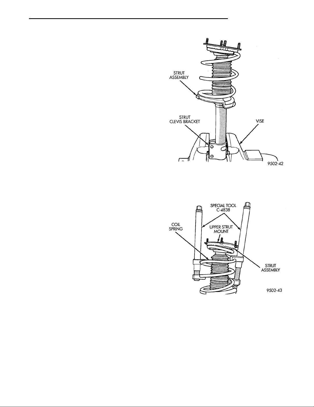
STRUT ASSEM-BLY VISESTRUT CLEVIS BRACKET
SPECIAL TOOL C-4838 STRUT ASSEM-BLYCOIL SPRING UPPER STRUTMOUNT
PL SUSPENSION 2 - 47
REMOVAL AND INSTALLATION (Continued)
(9) With suspension supporting total weight of
vehicle, and lateral links at correct curb height,
torque both lateral link attaching bolts to 95 N·m (70
ft. lbs.).
(10) Check and reset rear wheel TOE to specifications if required. Refer to Front And Rear Toe Setting
Procedure in the Wheel Alignment Check And
Adjustment section in this group of the service manual for the required Toe setting procedure.
DISASSEMBLY AND ASSEMBLY
STRUT ASSEMBLY
DISASSEMBLY
The rear strut unit is not serviced and must be
replaced as an assembly if found to be defective. The
strut is available with 2 calibrations, be sure strut is
replaced with an assembly of the same calibration.
The components of the strut assembly listed below
are replaceable if found to be defective.
• Coil spring (Coil springs come in a standard rate
of 120 lb./in. be sure spring is replaced with a spring
of the same rate.)
• Dust shield
• Mount assembly
• Jounce Bumper
• Lower Spring Isolator
• Shaft Nut
(1) Remove strut assembly requiring service from
the vehicle. Refer to Strut Assembly Removal in Servicing Rear Struts, in this section of the service manual.
(2) Position strut assembly in a vise (Fig. 25).
Using paint or equivalent, mark the strut unit, lower
spring isolator, spring and upper strut mount for
indexing of the parts at assembly.
C-4838 on the strut assembly spring (Fig. 26). Compress coil spring until all load is removed from upper
strut mount assembly.
Fig. 25 Strut Assembly Mounted In Vise
(3) Position Spring Compressors, Special Tool
Fig. 26 Compressing Strut Assembly Coil Spring
Page 48
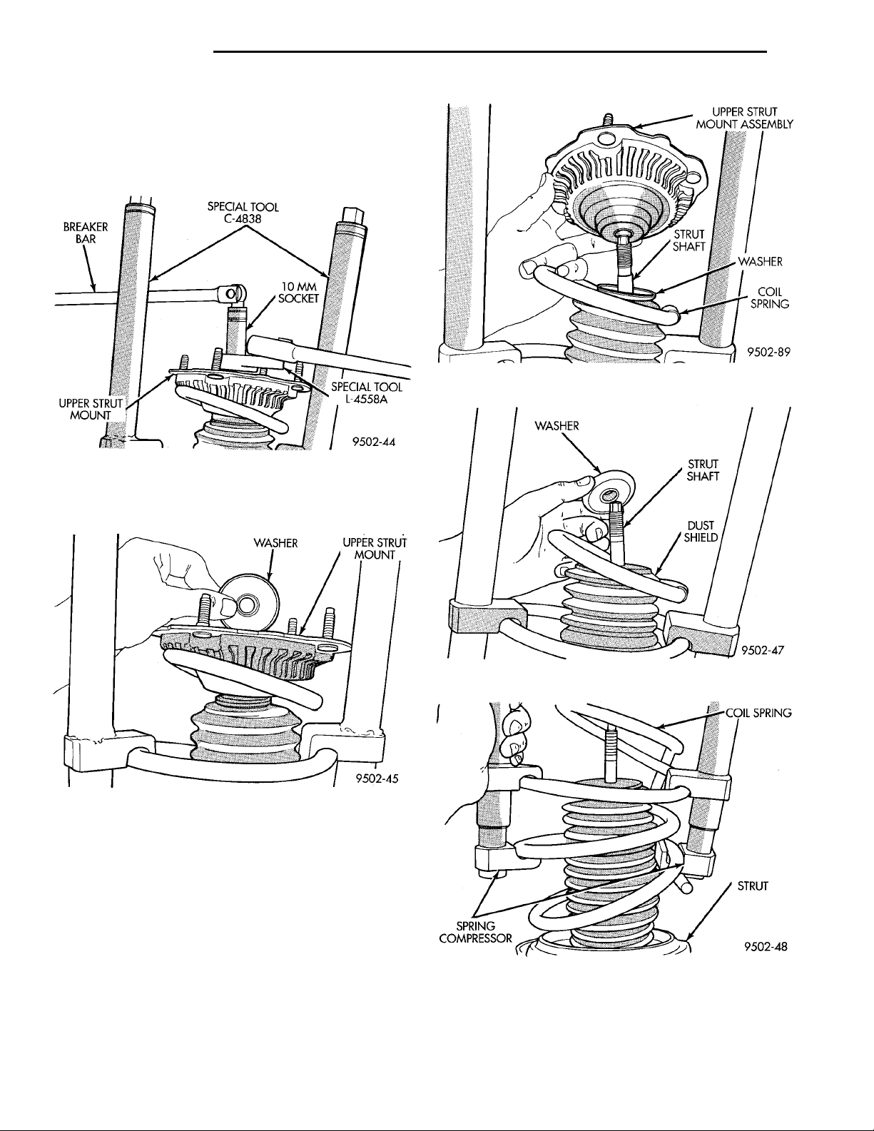
2 - 48 SUSPENSION PL
DISASSEMBLY AND ASSEMBLY (Continued)
BREAKERBAR
(4) Install Strut Rod Socket, Special Tool, L-4558A
UPPER STRUT
MOUNT
or L-4558 on strut shaft nut (Fig. 27). Inserted a 10
mm socket through special tool and onto end of strut
SPECIAL TOOL C-483810 MMSOCKET SPECIAL TOOLL-4558A
WASHER UPPER STRUT MOUNT
shaft (Fig. 27) to keep strut shaft from turning.
Remove strut shaft nut from strut shaft.
Fig. 27 Removing/Installing Strut Shaft Nut
(5) Remove washer (Fig. 28) between strut shaft
nut and upper strut mount and isolator.
WASHER STRUT SHAFTDUST SHIELD
Fig. 29 Upper Strut Mount
COIL SPRINGSTRUTSPRING COM-PRESSOR
Fig. 28 Strut Mount Washer
(6) Remove upper strut mount assembly from strut
shaft and spring (Fig. 29).
(7) Remove the washer from strut shaft, that is
between the strut upper mount assembly and dust
shield (Fig. 30).
(8) Remove the coil spring and spring compressor
as an assembly from the strut (Fig. 31).
(9) Remove the dust shield from the strut assembly (Fig. 32).
(10) Remove the jounce bumper (Fig. 33) from the
shaft of the strut assembly.
(11) Remove the coil spring lower isolator from the
strut assembly spring seat (Fig. 34).
Fig. 30 Washer
Fig. 31 Coil Spring And Compressor
(12) Inspect all disassembled components for signs
of abnormal wear or failure replacing any components as required. Inspect strut unit for signs of
abnormal oil leakage and for loss of gas charge. To
Page 49
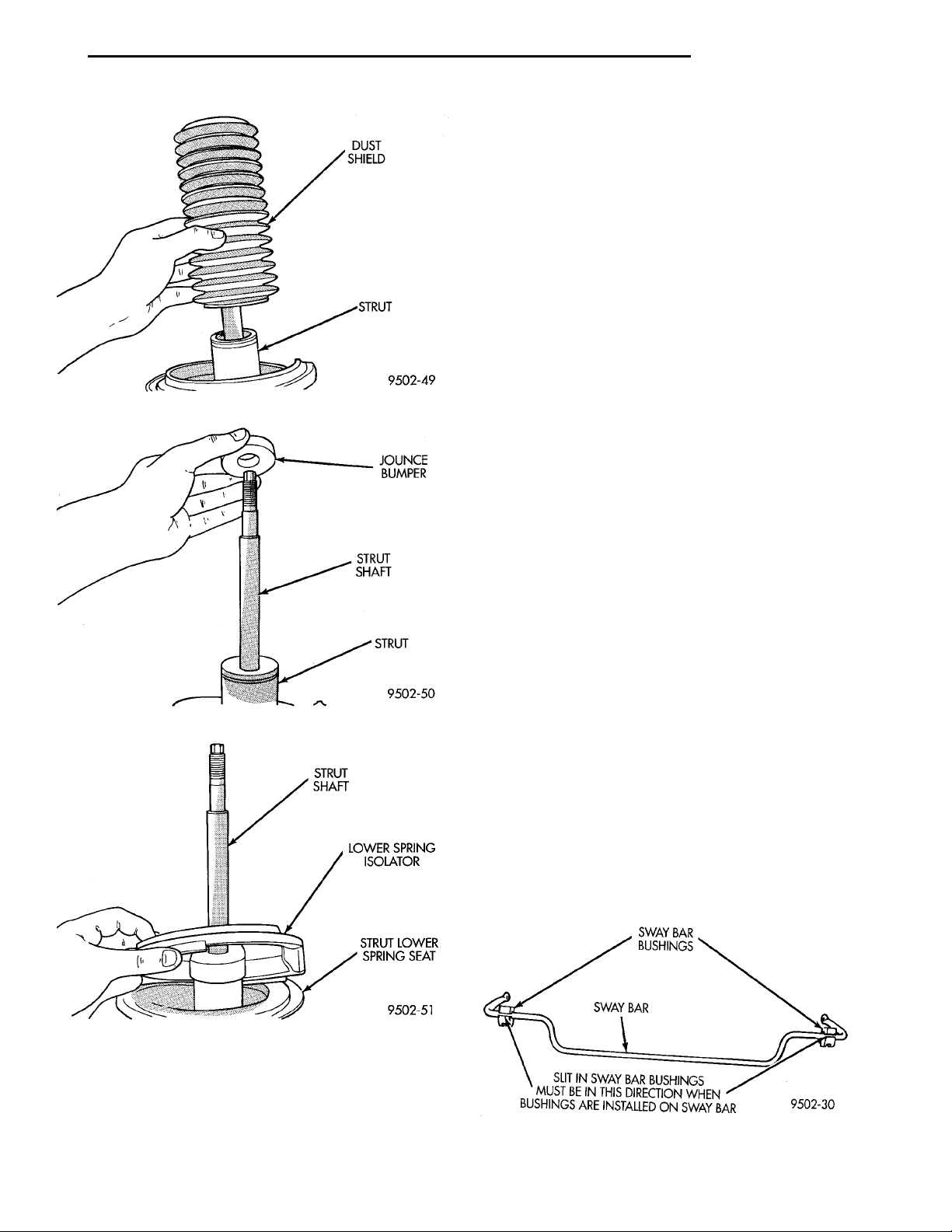
DUST SHIELDSTRUT
STRUT SHAFTLOWER SPRING ISOLATORSTRUT LOWER SPRINGSEAT
JOUNCEBUMPERSTRUT SHAFTSTRUT
SWAY BARBUSHINGSSWAY BARSLIT IN SWAY BAR BUSHINGS MUST BEIN THIS DIRECTION WHEN BUSHINGSARE INSTALLED ON SWAY BAR
PL SUSPENSION 2 - 49
DISASSEMBLY AND ASSEMBLY (Continued)
ASSEMBLY
(1) Install the original or a new isolator on lower
spring seat of strut (Fig. 34).
(2) Install jounce bumper on strut shaft (Fig. 33).
(3) Install the dust shield on the strut assembly
(Fig. 32).
(4) Lower the coil spring onto the strut unit (Fig.
31). Position end of coil spring against edge of spring
isolator on lower spring seat of strut assembly.
(5) Install washer on strut shaft with raised edge
of washer facing upward (Fig. 30).
(6) Install the strut assembly upper mount onto
the strut shaft (Fig. 29).
(7) Install the washer on the strut assembly upper
mount (Fig. 28). Washer must be installed with the
Fig. 32 Dust Shield
raised edge of the washer facing down.
(8) Install the upper strut mount to strut shaft
retaining nut.
(9) Using Strut Rod Socket, Special Tool, L-4558A
and a 10 mm socket (Fig. 27) to keep strut shaft from
turning, torque the strut shaft nut to 61 N·m (45 ft.
lbs.).
(10) Equally loosen the Spring Compressors, Special Tool C-4838 until spring is seated on upper strut
mount and all tension is relieved from the spring
compressors.
(11) Install the strut assembly back into the vehicle. Refer to Strut Assembly Removal in Servicing
Rear Struts in this section of the service manual.
(12) Check and reset rear wheel TOE to specifications if required.
Fig. 33 Jounce Bumper
Fig. 34 Coil Spring Lower Isolator
check for loss of gas charge in strut unit. Push strut
shaft into body of strut and release, strut shaft
should return to its fully extended position. If strut
shaft does not return to its fully extended position
replace strut unit.
STABILIZER BAR BUSHINGS
(1) If stabilizer bar to frame rail bushings require
replacement at time of inspection, install new bushings before installing stabilizer bar. Bushings are
replaced by opening slit on bushings and peeling
them off stabilizer bar. Install new bushings on stabilizer bar, by spreading bushing at slit and forcing
them on stabilizer bar. Bushings must be installed
on stabilizer bar with slit in bushing facing
rear of vehicle when stabilizer bar is installed
(Fig. 35).
Fig. 35 Correct Stabilizer Bushing Installation
Page 50
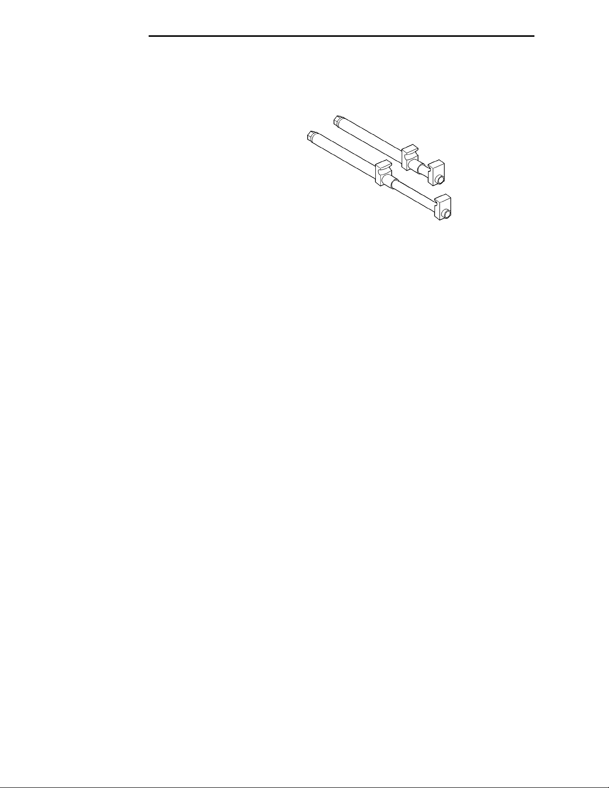
2 - 50 SUSPENSION PL
SPECIFICATIONS
REAR SUSPENSION FASTENER TORQUE
SPECIFICATIONS
DESCRIPTION TORQUE
STRUT ASSEMBLY:
To Body Attaching Nuts ......34N·m(300 in. lbs.)
Clevis Bracket To Knuckle
Nut/Bolt .................95N·m(70ft.lbs.)
Strut Assembly Shaft Nut .....75N·m(55ft.lbs.)
BRAKE SUPPORT PLATE:
To Knuckle Bolts ............68N·m(50ft.lbs.)
STABILIZER BAR:
Bushing Retainer To
Frame Bolt ..............34N·m(300 in. lbs.)
To Strut Attaching Link Nut . . 34 N·m (300 in. lbs.)
TENSION STRUT:
Shaft Nut ..................95N·m(70ft.lbs.)
Bracket To Body
Attaching Bolts ............95N·m(70ft.lbs.)
LATERAL LINK:
Attaching Nut ...............95N·m(70ft.lbs.)
DISC BRAKE CALIPER:
To Adapter Mounting Bolt .....22N·m(16ft.lbs.)
Brake Hose To Caliper
Mounting Bolt ............45N·m(35ft.lbs.)
Adapter To Knuckle
Mounting Bolt ............68N·m(50ft.lbs.)
BRAKE HOSE:
Bracket Mounting Bolt ........23N·m(17ft.lbs.)
HUB AND BEARING:
To Knuckle Retaining Nut . . . 216 N·m (160 ft. lbs.)
Wheel Stud Lug Nuts
(All Wheel Types) ...............109-150 N·m
(80-110 ft. lbs.)
SPECIAL TOOLS
REAR SUSPENSION
Compressor Strut Coil Spring C-4838
 Loading...