

Page 1

PL STEERING 19 - 1
STEERING
CONTENTS
page page
GENERAL INFORMATION .................. 1
POWER STEERING PUMP ................ 10
GENERAL INFORMATION
INDEX
page page
GENERAL INFORMATION
STEERING SYSTEM AND COMPONENT
DESCRIPTION ........................ 1
GENERAL INFORMATION
STEERING SYSTEM AND COMPONENT
DESCRIPTION
This vehicle comes with power steering as standard equipment and is the only steering system
available.
The power steering system consists of these six
major components. Power Steering Pump, Power
Steering Gear, Power Steering Reservoir, Power
Steering Supply and Pressure Hoses, and Power
Steering Fluid Return Hose. Turning of the steering
wheel is converted into linear travel through the
meshing of the helical pinion teeth with the rack
teeth. Power assist steering is provided by an open
center, rotary type control valve. It is used to direct
oil from the power steering pump to either side of the
integral steering rack piston.
Road feel is controlled by the diameter of a torsion
bar which initially steers the vehicle. As steering
effort increases as in a turn, the torsion bar twists,
causing relative rotary motion between the rotary
valve body and valve spool. This movement directs
oil behind the integral rack piston, which in turn,
builds up hydraulic pressure and assists in the turning effort.
STEERING COLUMN ..................... 35
STEERING GEAR ....................... 27
DIAGNOSIS AND TESTING
STEERING SYSTEM DIAGNOSIS CHARTS .... 1
DIAGNOSIS AND TESTING
STEERING SYSTEM DIAGNOSIS CHARTS
STEERING NOISE
There is some noise in all power steering systems.
One of the most common is a hissing sound evident
at standstill parking. Hiss is a very high frequency
noise similar to that experienced while slowly closing
a water tap. The noise is present in every valve and
results in high velocity fluid passing valve orifice
edges. There is no relationship between this noise
and performance of the steering. Hiss may be
expected when steering wheel at end of travel or
slowly turning at standstill.
Page 2
19 - 2 STEERING PL
DIAGNOSIS AND TESTING (Continued)
CONDITION POSSIBLE CAUSES CORRECTION
Objectionable Hiss Or Whistle 1. Damaged or mispositioned
steering column coupler to dash
panel seal.
2. Noisy valve in power steering
gear.
Rattle Or Clunk 1. Steering gear loose on front
suspension crossmember.
2. Front suspension crossmember to
frame bolts or studs loose.
3. Loose tie rod (outer or inner). 3. Check tie rod pivot points for
4. Loose lower control arm to front
suspension crossmember bolts.
5. Loose strut assembly to body
attaching bolts or nuts.
6. Power steering fluid pressure
hose touching the body of the
vehicle.
7. Noise internal to power steering
gear.
8. Damaged front suspension
crossmember.
1. Check for proper seal between
steering column coupler and dash
seal.
2. Replace steering gear assembly.
1. Check steering gear to front
suspension crossmember mounting
bolts. Tighten to the specified torque
if found to be loose.
2. Tighten the front suspension
crossmember attaching bolts or
studs to the specified torque.
wear. Replace worn/loose parts as
required.
4. Tighten control arm mounting
bolts to the specified torques.
5. Check upper strut mount to body
attaching bolts or nuts for looseness.
If required, tighten to the specified
torques.
6. Adjust hose to proper position by
loosening, repositioning, and
tightening fitting to specified torque.
Do not bend tubing.
7. Replace steering gear assembly.
8. Replace front suspension
crossmember.
Chirp or squeal (in the area of the
power steering pump). Particularly
noticeable at full wheel travel and
during standstill parking.
1. Loose power steering pump drive
belt.
1. Adjust power steering pump drive
belt to specified tension.
Page 3

PL STEERING 19 - 3
DIAGNOSIS AND TESTING (Continued)
CONDITION POSSIBLE CAUSES CORRECTION
Power steering pump growl results from the development of high pressure fluid flow. Normally this noise should
not be high enough to be objectionable. Abnormal situations, such as a low oil level causing aeration or hose
touching the vehicle body, can create a noise level that could bring complaints.
Whine Or Growl (Pump Noise) 1. Low fluid level. 1. Fill power steering fluid reservoir
to proper level and perform leakage
diagnosis. (Recheck fluid level after
power steering fluid is free of air.)
2. Power steering hose touching
vehicle body or frame.
3. Extreme wear of power steering
pump internal parts.
2. Reposition power steering hose.
Replace hose if tube ends are bent.
3. Replace power steering pump and
flush system.
Sucking Air Sound 1. Loose clamp on power steering
fluid low pressure hose.
2. Missing O-Ring on power steering
hose connection.
3. Low power steering fluid level 3. Fill power steering fluid reservoir
4. Air leak between power steering
fluid reservoir and power steering
pump.
SQUEAK OR RUBBING SOUND 1. Sound coming from steering
column.
2. Sound internal to steering gear. 1. Replace steering gear assembly.
SCRUBBING OR KNOCKING
SOUND
1. Incorrect tire size. 1. Verify that tire size on vehicle is
2. Check clearance between tires
and other vehicle components,
through the full travel of the
suspension.
3. Check for interference between
steering gear and other
components.
4.Incorrect steering gear supplied. 4. Replace steering gear with correct
1. Tighten or replace hose clamp.
2. Inspect connection and replace
O-Ring as required.
to proper level and perform leakage
diagnosis.
4. Inspect and or replace power
steering fluid reservoir as required.
1.Check for squeak in steering
column. Inspect for contact between
shroud, intermediate shaft, column,
and steering wheel. Realign if
necessary.
2. Check for lack or grease on
steering column dash panel to lower
coupler seal.
the same as originally supplied.
2. Correct as necessary.
3.Correct as necessary.
steering gear for specific vehicle.
Page 4
19 - 4 STEERING PL
DIAGNOSIS AND TESTING (Continued)
BINDING STICKING SEIZED
CONDITION POSSIBLE CAUSES CORRECTION
CATCHES, STICKS IN CERTAIN
POSITIONS OR IS DIFFICULT TO
TURN.
1. Low power steering fluid level. 1. Fill power steering fluid reservoir
to specified level and perform
leakage diagnosis.
2. Tires not inflated to specified
pressure.
3. Lack of lubrication in front
suspension control arm ball joints.
4. Lack of lubrication in front
suspension outer tie rod ends.
5. Loose power steering pump drive
belt.
6. Faulty power steering pump flow
control. (Verify cause using Power
Steering Pump Test Procedure.)
7. Excessive friction in steering
column or intermediate shaft.
8. Steering column coupler binding. 8. Realign the steering column to
9. Binding upper strut bearing. 9. Correct binding condition in strut
10 Excessive friction in steering
gear.
2. Inflate tires to the specified
pressure.
3. Lubricate ball joints if ball joints
are not a lubricated for life type ball
joint. If ball joint is a lubricated for
life ball joint, replace ball joint or
control arm.
4. Lubricate tie rod ends if they are
not a lubricated for life type. If tie rod
end is a lubricated for life type,
replace tie rod end.
5. Tighten the power steering pump
drive belt to the specified tension.
See accessory drive in service
manual.
6. Replace power steering pump.
7. Correct condition. (See Steering
Column Service Procedure)
eliminate the binding condition.
bearing.
10 Replace steering gear assembly.
Page 5
PL STEERING 19 - 5
DIAGNOSIS AND TESTING (Continued)
SHAKE SHUDDER VIBRATION
CONDITION POSSIBLE CAUSES CORRECTION
VIBRATION OF THE STEERING
WHEEL AND/OR DASH DURING
DRY PARK OR LOW SPEED
STEERING MANEUVERS.
1. Air in the fluid of the power
steering system.
2. Tires not properly inflated. 2. Inflate tires to the specified
3. Excessive engine vibration. 3. Ensure that the engine is running
4. Loose tie rod end. 4. Check that the inner to outer tie
5.Overcharged air conditioning
system.
LOW ASSIST, NO ASSIST, HARD STEERING
CONDITION POSSIBLE CAUSES CORRECTION
STIFF, HARD TO TURN,
SURGES, MOMENTARY
INCREASE IN EFFORT WHEN
TURNING.
1. Tires not properly inflated. 1. Inflate tires to specified pressure.
2. Low power steering fluid level. 2. Add power steering fluid as
3. Loose power steering pump drive
belt.
4. Lack of lubrication in control arm
ball joints.
5. Low power steering pump
pressure. (Verify using Power
Steering System Test Procedure)
6. High internal leak in steering gear
assembly.
1. Steering shudder can be expected
in new vehicles and vehicles with
recent steering system repairs.
Shudder should improve after the
vehicle has been driven several
weeks.
pressure.
properly.
rod jam nut for is tight. If required,
tighten the jam nut to the specified
torque.
5.Check air conditioning pump head
pressure. (See Air Conditioning
Refrigerant System Diagnosis)
required to power steering fluid
reservoir to obtain proper level.
Perform leakage diagnosis on power
steering system.
3. Adjust the power steering pump
drive belt to the specified tension. If
drive belt is defective replace and
correctly tension.
4. Lubricate ball joints if ball joints
are not a lubricated for life type ball
joint. If ball joint is a lubricated for
life ball joint, replace ball joint or
control arm.
5. Verify cause using the Power
Steering System Test Procedure.
Replace the power steering pump if
necessary.
6. Check steering system using the
Power Steering System Test
Procedure. If steering gear is
defective replace steering gear.
Page 6
19 - 6 STEERING PL
DIAGNOSIS AND TESTING (Continued)
POOR RETURN TO CENTER
CONDITION POSSIBLE CAUSES CORRECTION
STEERING WHEEL DOES NOT
WANT TO RETURN TO CENTER
POSITION.
1. Tires not
inflated to specified pressure.
2. Improper front wheel alignment. 2. Check and adjust as necessary.
3. Lack of lubrication in front
suspension control arm ball joints.
4. Steering column U-joints
misaligned.
5.
Mispositioned dash cover.
6. Steering wheel rubbing. 6. Adjust steering column shrouds to
7. Damaged, mis-positioned or
un-lubricated steering column
coupler to dash seal.
8. Binding upper strut bearing. 8. Correct
9. Tight shaft bearing
in steering column assembly.
10. Excessive friction in steering
column coupler.
11. Excessive friction in steering
gear.
1. Inflate tires to specified pressure.
3. Lubricate ball joints if ball joints
are not a lubricated for life type of
ball joint. If ball joint is a lubricated
for life ball joint, replace ball joint or
control arm.
4. Realign steering column U-joints.
5. Reposition dash cover.
To
evaluate items 6 and 7, disconnect
the intermediate shaft. Turn the
steering wheel and feel or listen for
internal rubbing in steering column.
eliminate rubbing condition.
7. Determine condition which exists
and correct.
binding condition in strut bearing.
9. Replace the steering column
assembly.
10. Replace steering column coupler.
11. Replace steering gear.
Page 7
PL STEERING 19 - 7
DIAGNOSIS AND TESTING (Continued)
LOOSE STEERING
CONDITION POSSIBLE CAUSES CORRECTION
EXCESSIVE STEERING WHEEL
KICKBACK OR TO MUCH
STEERING WHEEL FREE PLAY.
1. Air in the fluid of the power
steering system.
2. Steering gear loose on front
suspension crossmember.
3. Worn, broken or loose steering
column to steering gear coupler.
4. Free play in steering column. 4.Check components of the steering
5. Loose front suspension control
arm ball joints.
6. Loose steering knuckle to ball
joint stud pinch bolt.
7. Front wheel bearings loose or
worn.
8. Loose outer tie rod ends. 8. Check free play of outer tie rod
9. Loose inner tie rod ends. 9. Replace steering gear assembly.
10 Defective steering gear rotary
valve.
1. Fill power steering fluid reservoir
to the specified level. Perform
procedure to bleed the air out of the
power steering system. Perform
leakage diagnosis.
2. Check steering rear to front
suspension crossmember mounting
bolts. Tighten to specified torque if
found to be loose.
3. Check for worn universal joint,
broken isolator or loose fasteners.
system and repair or replace as
required.
5. Check and or replace the ball joint
or control arm as required.
6. Check pinch bolts and tighten if
required to specified torque.
7. Tighten hub nut to specified
torque or replace with new parts as
necessary.
ends and replace if required.
10. Replace steering gear assembly.
Page 8
19 - 8 STEERING PL
DIAGNOSIS AND TESTING (Continued)
VEHICLE LEADS TO THE SIDE
CONDITION POSSIBLE CAUSES CORRECTION
STEERING WHEEL DOES NOT
WANT RETURN TO CENTER
POSITION.
STEERING WHEEL HAS FORE
AND AFT LOOSENESS.
1. Radial tire lead. 1.Rotate tires as recommended in
the Tire And Wheel Group of this
service manual.
2. Front suspension misaligned. 2. Align the front suspension as
required. Refer to the Wheel
Alignment Procedure in the
Suspension Group of this service
manual for the required wheel
alignment procedure.
3. Wheel braking. 3. Check for dragging brakes. Refer
to the procedures in the Brake
Group of this service manual.
4. Unbalanced steering gear valve.
(If this is the cause, the steering
efforts will be very light in direction
of lead and heavier in the opposite
direction.
1. Steering wheel to steering column
shaft retaining nut not properly
tightened and torqued.
2. Steering column lower bearing
spring retainer slipped on steering
column shaft.
4. Replace steering gear.
1. Tighten the retaining nut to its
specified torque specification.
2. Replace steering column.
Page 9
PL STEERING 19 - 9
DIAGNOSIS AND TESTING (Continued)
POWER STEERING FLUID LEAK
CONDITION POSSIBLE CAUSES CORRECTION
LOW FLUID LEVEL WITH: NO
VISIBLE SIGNS OF A LEAK ON
THE STEERING GEAR, POWER
STEERING PUMP, FLOOR OR
ANYWHERE ELSE.
LOW FLUID LEVEL WITH:
VISIBLE LEAK ON STEERING
GEAR, POWER STEERING
PUMP, FLOOR OR ANYWHERE
ELSE.
1. Overfilled power steering pump
fluid reservoir.
2. Power steering hose connections
at the power steering pump or
steering gear.
3. Power steering pump or power
steering gear leaking.
FOAMY OR MILKY POWER STEERING FLUID
CONDITION POSSIBLE CAUSES CORRECTION
AERATION AND OVERFLOW OF
FLUID.
1. Air leaks. 1. Check for an air leak into the
2. Low fluid level. 2. Extremely cold temperatures may
3. Cracked power steering pump
housing.
4. Water contamination. 4. Drain the power steering fluid
1. Adjust the power steering fluid fill
to the correct level.
2. Check for loose fittings and if
found, tighten the fitting to its
specified torque. If fittings are tight
examine the fittings for damaged or
missing O-ring seals and replace as
required.
3. Identify the location of the leak
and repair or replace the component
as required. Refer to Power Steering
Pump and/or Power Steering Gear in
this group of the service manual for
required procedures.
power steering system as described
under Sucking Air Diagnosis and
correct condition.
cause power steering fluid aeration if
the power steering fluid is low. Add
power steering fluid as required to
bring level up to specification.
3. Remove power steering pump
from vehicle and inspect the power
steering pump housing for cracks. If
a defect in the housing is found,
replace the power steering pump.
from the system if there is evidence
of contamination. Then refill the
system with fresh clean power
steering fluid.
Page 10
POWER STEERING PUMP FLUID SUP-
POWER STEERING
PUMP DISCHARGE
FITTING
PLY FITTING
POWER STEERING PUMPHOUSINGPOWER STEERINGPUMP SHAFT
19 - 10 STEERING PL
POWER STEERING PUMP
INDEX
page page
DESCRIPTION AND OPERATION
POWER STEERING PUMP ............... 10
DIAGNOSIS AND TESTING
POWER STEERING SYSTEM TEST
PROCEDURE ........................ 11
SERVICE PROCEDURES
POWER STEERING PUMP FLOW CONTROL
VALVE SEAL ......................... 12
POWER STEERING PUMP INITIAL OPERATION
...................................... 12
POWER STEERING PUMP SUCTION PORT
SEAL .............................. 13
POWER STEERING SYSTEM FLUID LEVEL
CHECK ............................. 12
REMOVAL AND INSTALLATION
POWER STEERING FLUID PRESSURE
HOSE .............................. 14
DESCRIPTION AND OPERATION
POWER STEERING PUMP
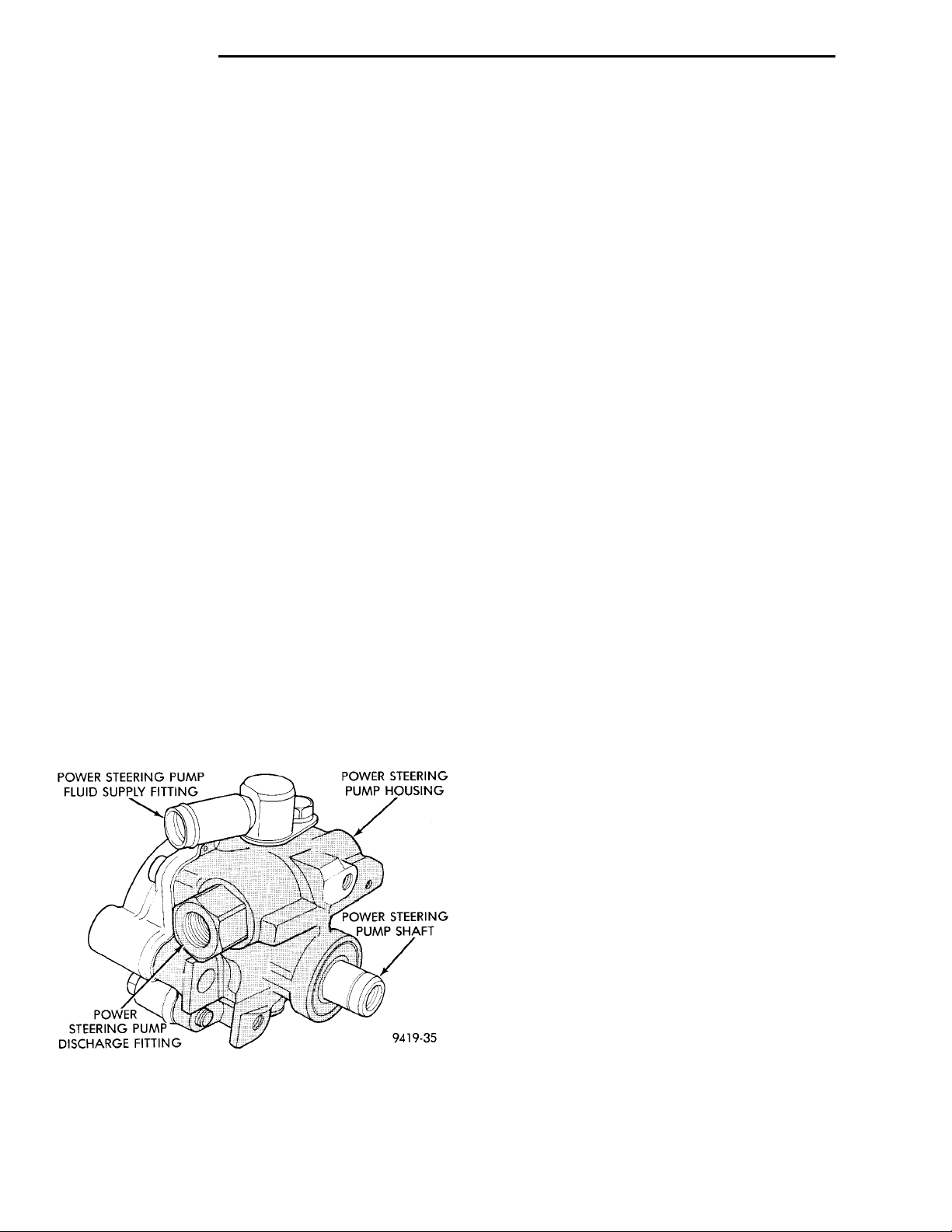
On all vehicles equipped with power steering, the
hydraulic pressure for operation of the power steering gear is provided by a belt driven power steering
pump (Fig. 1). The TTA power steering pump is a
constant flow rate and displacement, vane type
pump.
Fig. 1 TTA Power Steering Pump Assembly
In the event of a power steering pump drive belt
failure, manual steering control of the vehicle can
still be maintained. However, under these conditions,
steering effort will be significantly increased.
POWER STEERING FLUID RESERVOIR ..... 22
POWER STEERING FLUID RETURN HOSE . . . 16
POWER STEERING FLUID SUPPLY HOSE
RESERVOIR TO POWER STEERING PUMP . 18
POWER STEERING PRESSURE SWITCH .... 13
POWER STEERING PUMP (ALL ENGINES) . . . 19
DISASSEMBLY AND ASSEMBLY
POWER STEERING PUMP DRIVE PULLEY . . . 23
POWER STEERING PUMP MOUNTING
BRACKET ........................... 24
SPECIFICATIONS
POWER STEERING PUMP FASTENER
TORQUE SPECIFICATIONS ............. 26
POWER STEERING PUMP FLOW
SPECIFICATIONS ..................... 25
SPECIAL TOOLS
POWER STEERING PUMP ............... 26
All vehicles equipped with power steering use a
remote mounted reservoir for the power steering
fluid. The power steering fluid remote reservoir is
mounted to the rear of the cylinder head on the passenger side of the vehicle.
The service procedures for the TTA power steering
pump are limited to the areas and components listed
below. No repair procedures are to be done on
internal components of the TTA power steering
pumps.
• Repair of power steering fluid leaks from areas
of the power steering pump sealed by O-rings is
allowed (See Pump Leak Diagnosis). However power
steering pump shaft seal leakage will require
replacement of the pump.
• Power steering fluid reservoirs, related components and attaching hardware.
• Power steering fluid reservoir filler cap/dipstick
assemblies.
Because of unique shaft bearings, flow control levels or pump displacements, power steering pumps
may be used only on specific vehicle applications. Be
sure that all power steering pumps are only replaced
with a pump that is the correct replacement for that
specific application.
Hydraulic pressure is provided for operation of the
power steering gear by the belt driven power steering
pump id (Fig. 1). It is a constant displacement, vane
type pump. The power steering pump is connected to
the steering gear by a power steering fluid pressure
hose and return hose.
Page 11
PRESSURE HOSETO POWERSTEERING GEAR SPECIALTOOL 6815POWER STEER-ING PUMPTO POWERSTEERINGPUMP
SPECIAL TOOL6815 ADAPTER FIT-TINGS
PL STEERING 19 - 11
DESCRIPTION AND OPERATION (Continued)
Rectangular pumping vanes in the shaft driven
rotor, move power steering fluid from the intake to
the cam ring pressure cavities of the power steering
pump. As the rotor begins to turn, centrifugal force
throws the vanes against the inside surface of the
cam ring to pickup residual oil. This oil is then forced
into the high pressure area. As more oil is picked up
by the vanes, the additional oil is forced into the cavities of the thrust plate through two crossover holes
in the cam ring and pressure plate. The crossover
holes empty into the high pressure area between the
pressure plate and the housing end cover.
As the high pressure area is filled, oil flows under
the vanes in the rotor slots, forcing the vanes to follow the inside surface of the cam ring. As the vanes
reach the restricted area of the cam ring, oil is forced
out from between the vanes. When excess oil flow is
generated during high-speed operation, a regulated
amount of oil returns to the pump intake side
through a flow control valve. The flow control valve
reduces the power required to drive the pump and
holds down temperature build-up.
When steering conditions exceed maximum pressure requirements, such as when the wheels are
turned against the stops. The pressure built up in
the steering gear exerts pressure on the spring end of
the flow control valve. The high pressure lifts the
relief valve ball from its seat and allows oil to flow
through a trigger orifice located in the outlet fitting.
This reduces pressure on the spring end of the flow
control valve which then opens and allows the oil to
return to the intake side of the pump. This action
limits maximum pressure output of the pump to a
safe level.
Under normal power steering pump operating conditions, pressure requirements of the pump are below
maximum, causing the pressure relief valve to
remain closed.
Fig. 2 Power Steering Pump Flow/Pressure Tester
POWER STEERING PUMP FLOW AND PRESSURE TEST PROCEDURE
(1) Check power steering pump drive belt tension
and adjust as necessary.
(2) Disconnect power steering fluid pressure hose,
at power steering pump. Use a container for dripping
fluid.
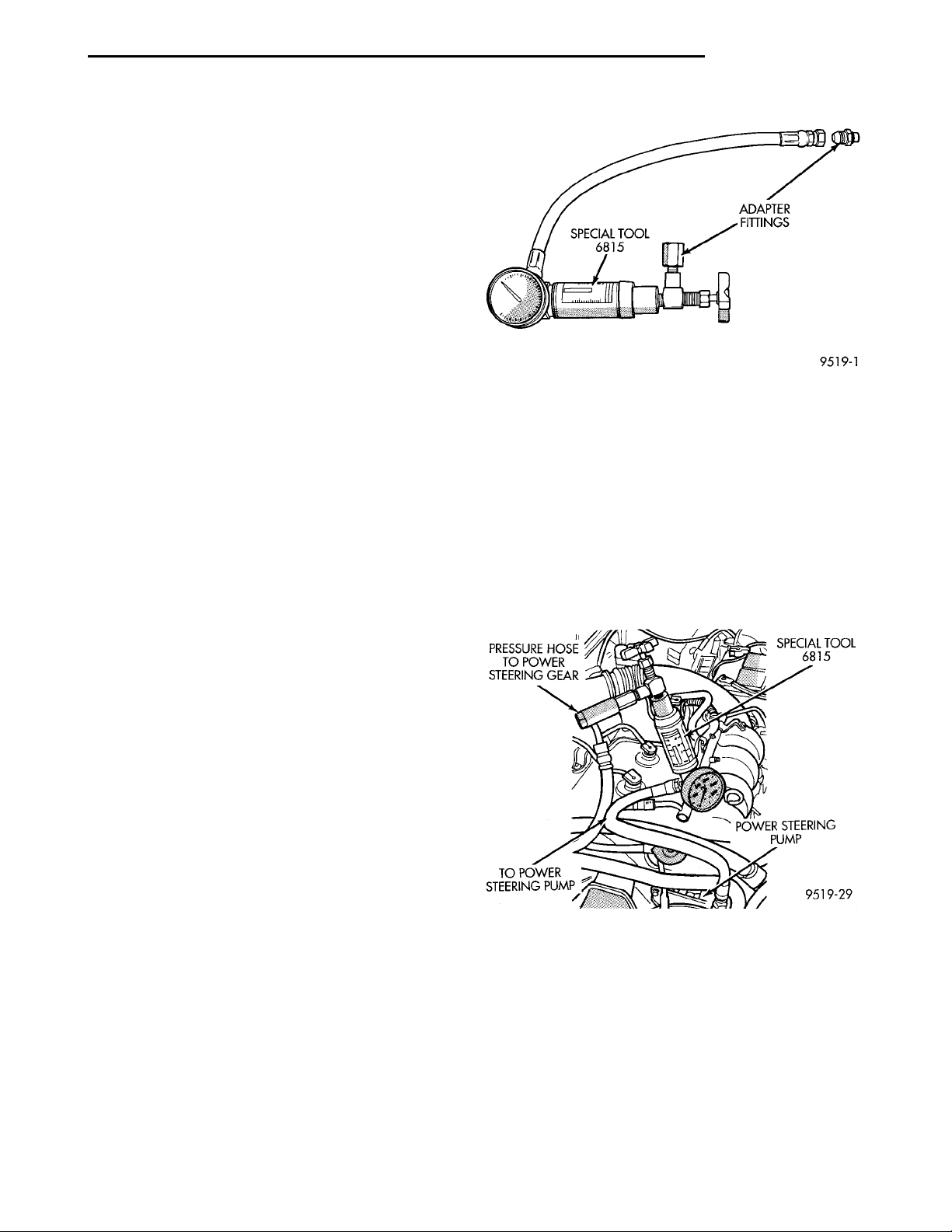
(3) Connect Pressure Gauge, Special Tool from kit
6815 (Fig. 3) to both hoses using adapter fittings.
Connect spare pressure hose, to power steering pump
pressure hose banjo fitting.
DIAGNOSIS AND TESTING
POWER STEERING SYSTEM TEST PROCEDURE
The following procedure can be used to test the
operation of the power steering system on the vehicle. This test will provide the flow rate of the power
steering pump along with the maximum relief pressure. This test is to be performed any time a power
steering system problem is present to determine if
the power steering pump or power steering gear is
not functioning properly. The following pressure and
flow test is performed using Pressure/Flow Tester,
Special Tool 6815 (Fig. 2).
Fig. 3 Power Steering Pump Flow/Pressure Tester
Connected To Power Steering Pump
(4) Completely open valve on Special Tool 6815
(Fig. 3).
(5) Start engine and let idle long enough to circulate power steering fluid through flow/pressure test
and get air out of fluid. Then shut off engine.
(6) Check power steering fluid level, and add fluid
as necessary. Start engine again and let idle.
(7) Pressure gauge should read below 862 kPa
(125 psi), if above, inspect the hoses for restrictions
and repair as necessary. The initial pressure reading
Page 12

19 - 12 STEERING PL
DIAGNOSIS AND TESTING (Continued)
should be in the range of 345-552 kPa (50-80 psi).
The flow meter should read between 1.3 and 1.4
GPM
CAUTION: The following test procedure involves
testing power steering pump maximum pressure
output and flow control valve operation. Do not
leave valve closed for more than 5 seconds as the
pump could be damaged.
(8) Close valve fully three times and record high-
est pressure indicated each time. All three read-
ings must be above specifications and within
345 kPa (50 psi) of each other.
NOTE: Power steering pump maximum relief pressure is 8240 to 8920 kPa (1195 to 1293 psi.).
• If power steering pump pressures above specifications but not within 345 kPa (50 psi) of each other,
then replace power steering pump.
• If pressures within 345 kPa (50 psi) of each
other but below specifications, then replace power
steering pump.
CAUTION: Do not force the pump to operate
against the stops for more than 5 seconds at a time
because, pump damage will result.
(9) Open test valve. Turn steering wheel to the
extreme left and right positions until against the
stops, recording the highest indicated pressure at
each position. Compare pressure gauge readings to
power steering pump specifications. If highest output
pressures are not the same against either stop, the
steering gear is leaking internally and must be
replaced.
POWER STEERING PUMP INITIAL OPERATION
CAUTION: The fluid level should be checked with
engine off to prevent injury from moving components. Use only MoparT Power Steering Fluid. Do
not use automatic transmission fluid. Do not overfill.
Wipe filler cap clean, then check the fluid level.
The dipstick should indicate FULL COLD when the
fluid is at normal temperature of approximately 21°C
to 27°C (70°F to 80°F).
(1) Fill the pump fluid reservoir to the proper level
and let the fluid settle for at least two (2) minutes.
(2) Start the engine and let run for a few seconds.
Then turn the engine off.
(3) Add fluid if necessary. Repeat the above procedure until the fluid level remains constant after running the engine.
(4) Raise the front wheels off the ground.
(5) Start the engine. Slowly turn the steering
wheel right and left, lightly contacting the wheel
stops.
(6) Add power steering fluid if necessary.
(7) Lower the vehicle and turn the steering wheel
slowly from lock to lock.
(8) Stop the engine. Check the fluid level and refill
as required.
(9) If the fluid is extremely foamy, allow the vehicle to stand a few minutes and repeat the above procedure.
POWER STEERING PUMP FLOW CONTROL VALVE SEAL
The power steering pump does not require removal
from the engine for removal and replacement of the
flow control valve fitting O-Ring.
SERVICE PROCEDURES
POWER STEERING SYSTEM FLUID LEVEL CHECK
WARNING: FLUID LEVEL SHOULD BE CHECKED
WITH ENGINE OFF TO PREVENT INJURY FROM
MOVING PARTS. DO NOT USE AUTOMATIC TRANSMISSION FLUID IN THE POWER STEERING SYSTEM. DO NOT OVERFILL THE POWER STEERING
SYSTEM.
Wipe reservoir filler cap free of dirt. Then check
fluid level. The dipstick should indicate COLD when
fluid is at normal ambient temperature, approximately 21°C to 27°C (70°F to 80°F). In all pumps add
fluid as necessary, use only Mopar Power Steering
Fluid, or equivalent. DO NOT USE ANY TYPE
OF AUTOMATIC TRANSMISSION FLUID.
REMOVE
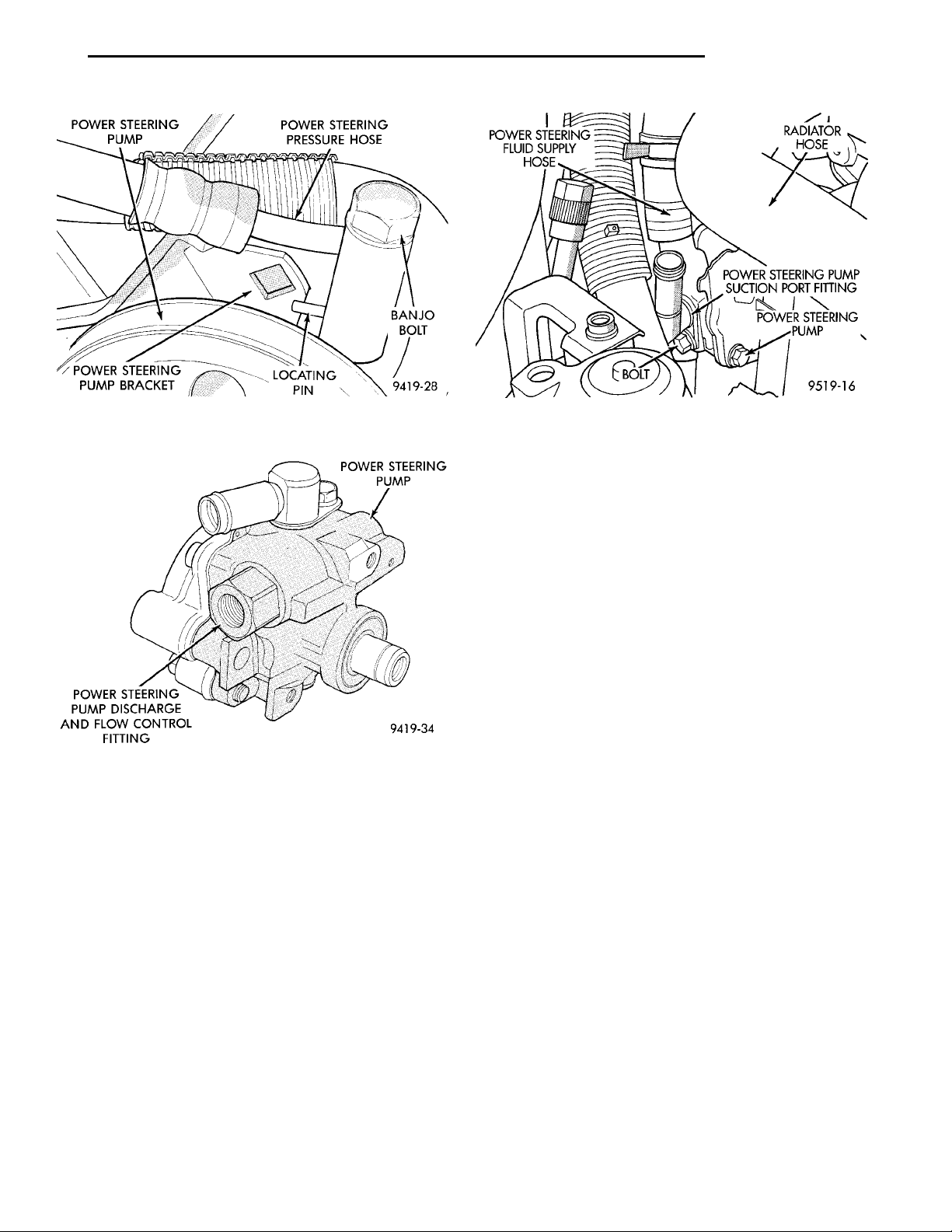
(1) Remove the power steering fluid pressure hose
from the power steering pump pressure fitting (Fig.
4).
(2) Remove the flow control valve fitting from the
power steering pump housing (Fig. 5). Prevent flow
control valve and spring from sliding out of
housing bore.
(3) Remove and discard O-ring seal from fitting.
INSTALL
(1) If necessary, clean and install flow control
valve and spring in pump housing bore.
(2) Install new O-ring seal on fitting.
(3) Install fitting in pump housing and tighten to
75 N·m (55 ft. lbs.)
(4) Install power steering fluid pressure hose on
flow control valve fitting.
Page 13
POWER STEER-ING PUMP POWER STEERING PRES-SURE HOSEPOWER STEER-ING PUMPBRACKET LOCATING PIN BANJO BOLT
POWER STEERINGPUMPPOWER STEERING PUMPDISCHARGE AND FLOWCONTROL FITTING
POWER STEERING FLUIDSUPPLY HOSE RADIATOR HOSE
POWER STEERING PUMPBOLT
POWER STEERING PUMP SUCTION
PORT FITTING
PL STEERING 19 - 13
SERVICE PROCEDURES (Continued)
Fig. 4 Pressure Hose Attachment To Power Steering
Pump
Fig. 5 Pump Discharge And Flow Control Valve
Fitting
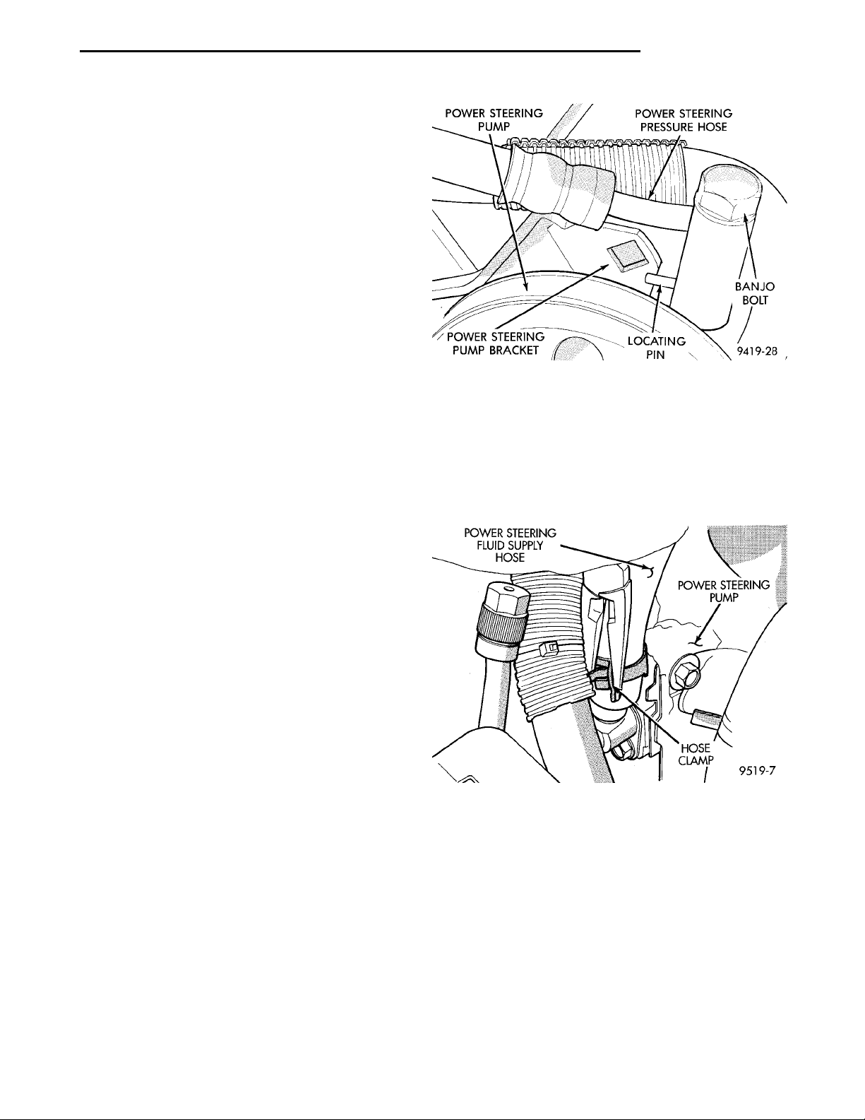
(5) Position locating pin on power steering pressure hose banjo fitting so it is against power steering
pump mounting bracket (Fig. 4). While holding locating pin against power steering pump bracket, torque
banjo bolt to 34 N·m (25 ft. lbs.).
POWER STEERING PUMP SUCTION PORT SEAL
The power steering pump does not require removal
from the engine for removal and replacement of the
suction port O-Ring seal.
REMOVE
(1) Remove power steering fluid supply hose from
power steering pump suction port fitting (Fig. 6).
(2) Remove bolt (Fig. 6) attaching power steering
pump suction port fitting to the power steering
pump.
(3) Remove the suction port fitting (Fig. 6) from
the power steering pump.
Fig. 6 Power Steering Pump Suction Port Fitting
(4) Remove and discard O-ring seal from suction
port fitting.
INSTALL
(1) Install new O-ring seal on suction fitting.
(2) Install suction port fitting in power steering
pump. Install and securely tighten the suction port
fitting attaching bolt.
(3) Install power steering fluid supply hose on suction port fitting, being sure hose clamp is installed on
hose past upset bead on suction port fitting.
REMOVAL AND INSTALLATION
POWER STEERING PRESSURE SWITCH
On vehicles equipped with power steering, a power
steering pressure switch is used to improve the vehicle’s idle quality. The pressure switch improves vehicle idle quality, by controlling engine idle speed when
required.
The pressure switch functions by signaling the
power train control module, that the power steering
system is putting additional load on the engine. This
type of condition exists when turning the front tires
of the vehicle, when the vehicle is stationary and the
engine is at idle speed. When this condition is sensed
by the power train control module, through a signal
from the power steering pressure switch, engine idle
speed is increased. This increase in engine idle speed
compensates for the additional load, thus maintaining the require engine idle speed and idle quality.
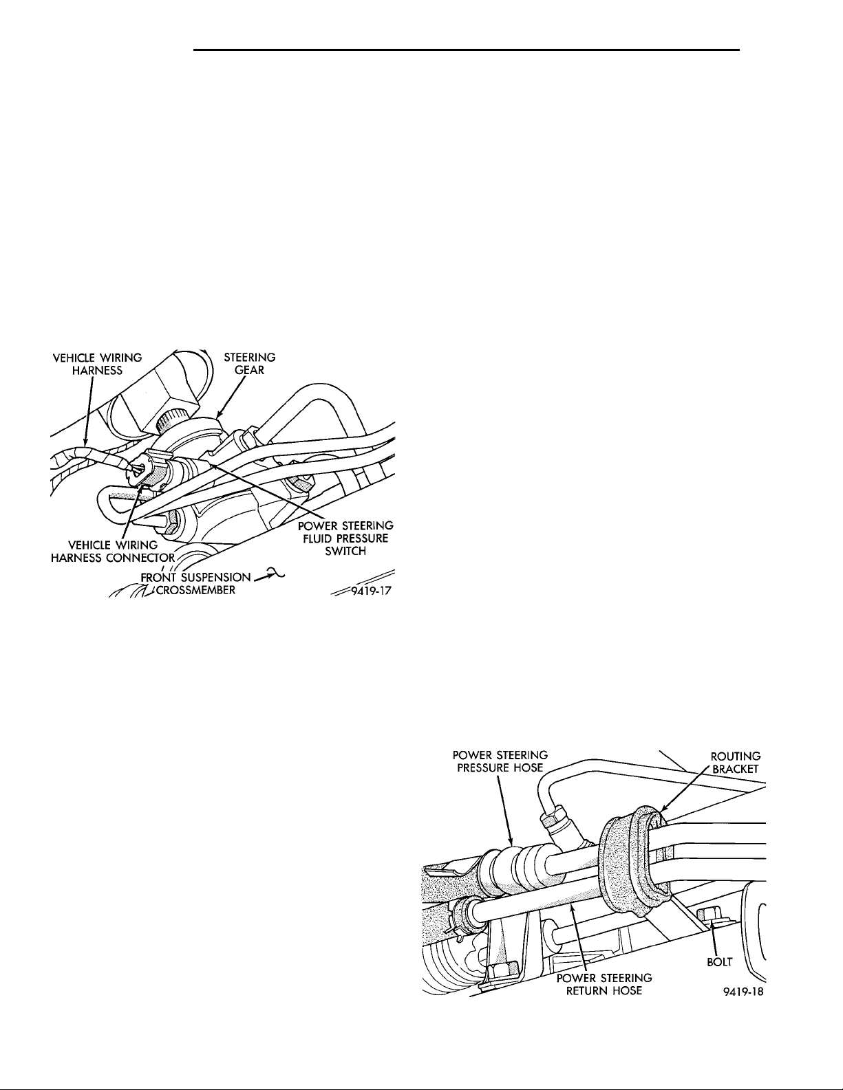
The power steering pressure switch (Fig. 7) is
mounted directly to the power steering gear on vehicle’s requiring its usage.
Page 14
VEHICLE WIR-ING HARNESS STEERING GEARVEHICLE WIRING HAR-NESS CONNECTOR FRONT SUSPENSIONCROSSMEMBER POWER STEERINGFLUID PRESSURESWITCH
POWER STEERING PRES-SURE HOSE ROUTING BRACKETPOWER STEERING RETURNHOSE BOLT
19 - 14 STEERING PL
REMOVAL AND INSTALLATION (Continued)
REMOVE
CAUTION: When removing and installing the
power steering pressure switch, the use of a 7/8
inch deep well socket is required. The deep well
socket will prevent damage to the plastic, electrical
connector area, of the power steering pressure
switch.
(1) Disconnect negative battery cable from the negative post of the battery. Be sure cable is isolated
from negative post on battery.
(2) Raise vehicle.
(3) Locate power steering pressure switch (Fig. 7)
on back side of power steering gear.
CAUTION: Do not use automatic transmission fluid
in power steering system. Only use MoparT, Power
Steering Fluid, or equivalent.
(3) Fill power steering reservoir to correct fluid
level.
(4) Connect negative cable back on negative post of
battery.
(5) Start engine and turn steering wheel several
times from stop to stop to bleed air from fluid in system. Stop engine, check fluid level, and inspect system for leaks. See Checking Fluid Level.
POWER STEERING FLUID PRESSURE HOSE
CAUTION: Cap all open ends of hoses, power
steering pump fittings and steering gear ports to
prevent entry of foreign material into the components.
WARNING: POWER STEERING OIL, ENGINE
PARTS AND EXHAUST SYSTEM MAY BE
EXTREMELY HOT IF ENGINE HAS BEEN RUNNING.
DO NOT START ENGINE WITH ANY LOOSE OR DISCONNECTED HOSES. DO NOT ALLOW HOSES TO
TOUCH HOT EXHAUST MANIFOLD OR CATALYST.
Fig. 7 Power Steering Pressure Switch Location On
Steering Gear
(4) Remove vehicle wiring harness connector (Fig.
7), from power steering pressure switch.
(5) Remove power steering pressure switch, from
power steering gear.
INSTALL
CAUTION: When installing the power steering
pressure switch in the steering gear, do not exceed
the torque specification shown in step 1 below.
Over-torquing will result in stripping the threads out
of the power steering pressure switch port on the
steering gear.
(1) By hand, install the power steering pressure
switch into the power steering gear until fully seated.
Then tighten the power steering pressure switch to a
maximum torque of 8 N·m (70 in. lbs.).
(2) Install vehicle wiring harness connector (Fig. 7)
onto power steering pressure switch. Be sure latch on
wiring harness connector is fully engaged with locking tab on power steering pressure switch.
For part reference and part location on the vehicle
being serviced, refer to the following figure numbers.
These figures show the hose bracket locations, hose
routings and fitting locations. Use these figure numbers when referring to the removal or installation
procedures for the power steering hoses listed below.
REMOVE
(1) Raise vehicle.
(2) Remove bolt attaching power steering hose
routing bracket to front suspension crossmember
(Fig. 8).
Fig. 8 Power Steering Hose Routing Bracket
Page 15
STEERINGGEAR POWER STEERINGPRESSURE SWITCHPOWER STEERING FLUIDRETURN HOSEPOWER STEERINGFLUID PRESSUREHOSE
POWER STEERING PRES-SURE HOSETUBE CLIPPOWER STEERINGRETURN HOSEROUTING CLIPGENERATORSHIELDPOWER STEERING FLUIDRESERVOIR BOLT HOSECLAMP
ALTERNATORSHIELD ROUTING CLIP
POWER STEER-ING PUMP POWER STEERING PRES-SURE HOSEPOWER STEER-ING PUMPBRACKET LOCATING PIN BANJO BOLT
POWER STEERING PRES-SURE HOSEPOWER STEERING FLUIDRESERVOIR BOLT
TUBE CLIP
PL STEERING 19 - 15
REMOVAL AND INSTALLATION (Continued)
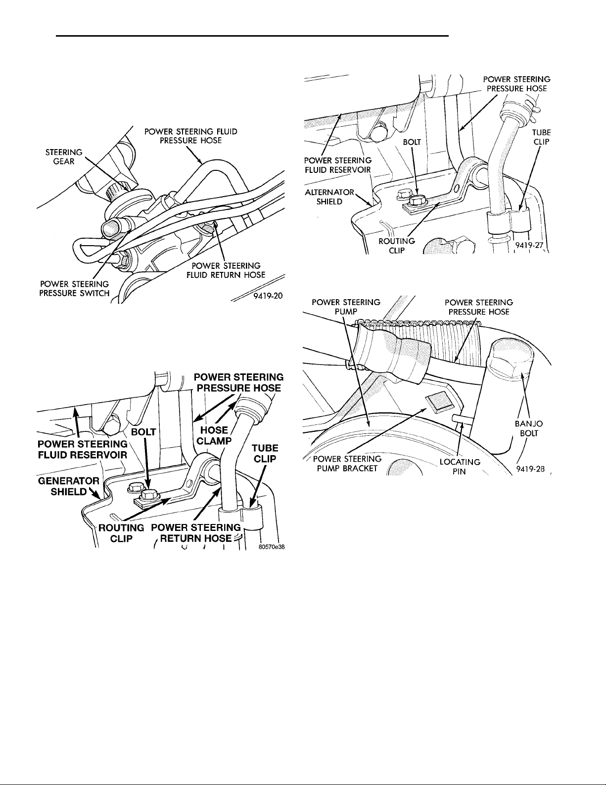
(3) Disconnect power steering pressure hose (Fig.
9) at power steering gear. Drain power steering fluid
from power steering pump and hose through open
end of hose.
Fig. 11 Power Steering Hose Attachment To
Generator Shield
Fig. 9 Power Steering Pressure Hose At Steering
Gear
(4) Remove power steering pressure hose from
routing clip on generator shield (Fig. 10).
Fig. 10 Power Steering Pressure Hose Routing Clip
At Generator Shield
(5) Lower vehicle.
(6) Remove bolt, attaching power steering pressure
hose routing clip, to generator shield (Fig. 11).
(7) Loosen and remove Banjo bolt, and power
steering pressure hose from pressure fitting on power
steering pump (Fig. 12).
(8) Power steering fluid pressure hose is removed
from the vehicle from the top of the engine compartment.
(9) Discard all used O-rings located at ends of
power steering pressure hose and Banjo bolt.
Fig. 12 Power Steering Hose Attachment To Power
Steering Pump
INSTALL
(1) Install power steering pressure hose in vehicle
from top of engine compartment.
(2) Using a lint free towel, wipe clean all open
power steering hose ends, and the power steering
pump and steering gear ports.
(3) Install new O-ring on end of power steering
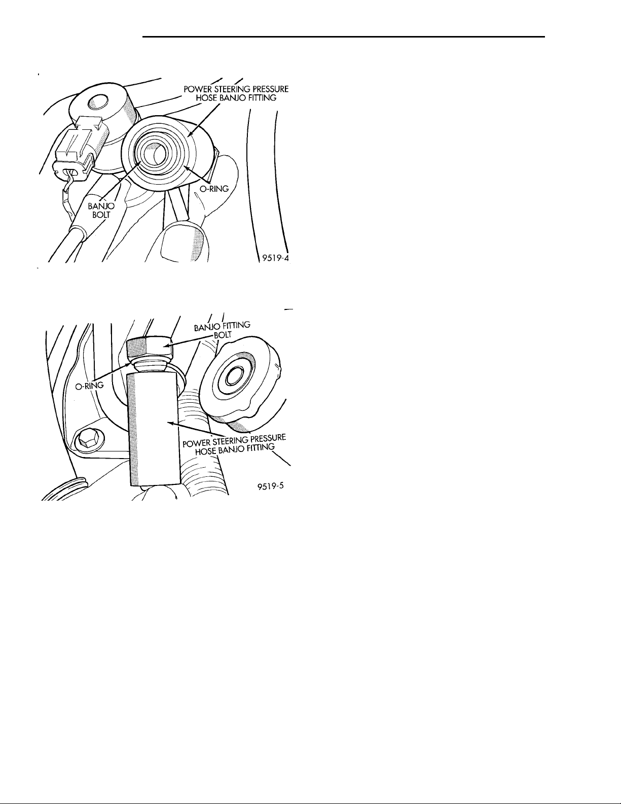
pressure hose banjo fitting (Fig. 13).
(4) Install a new O-ring (Fig. 14) on power steering
pressure hose banjo fitting bolt.
(5) Lubricate both O-rings using fresh clean power
steering fluid.
(6) Install banjo bolt into the power steering pressure hose banjo fitting (Fig. 14).
(7) Attach power steering pressure hose to outlet
fitting on power steering pump (Fig. 12). Do not
tighten or torque pressure fitting Banjo bolt at
this time.
Page 16
POWER STEERING PRESSUREHOSE BANJO FITTINGO-RING
BANJO BOLT
O-RING
BANJO FITTINGBOLT
POWER STEERING PRESSURE
HOSE BANJO FITTING
19 - 16 STEERING PL
REMOVAL AND INSTALLATION (Continued)
(11) Install the power steering pressure and return
hose routing clip on hoses (Fig. 8). Install bolt attaching routing clip to front suspension crossmember.
Torque routing clip to front suspension crossmember
attaching bolt to 23 N·m (17 ft. lbs.)
(12) Torque power steering pressure hose to steering gear tube nut to 34 N·m (25 ft. lbs.).
(13) Install power steering pressure hose in routing clip on generator shield (Fig. 10).
(14) Lower Vehicle.
(15) Position locating pin on power steering pressure hose banjo fitting so it is against power steering
pump mounting bracket (Fig. 12). While holding
locating pin against power steering pump bracket,
torque pump end Banjo bolt to 34 N·m (25 ft. lbs.).
(16) Securely tighten bolt attaching power steering
pressure hose bracket to generator shield.
Fig. 13 O-ring Installed On Power Steering Hose
Banjo Fitting
Fig. 14 O-ring Installed On Banjo Fitting Bolt
(8) Correctly route power steering pressure hose
avoiding tight bends or kinking of the hose. Install
power steering pressure hose to generator shield
routing clip attaching screw (Fig. 11) but do not
tighten at this time.
(9) Raise vehicle.
(17) Start the engine and let run for a few seconds.
Then turn the engine off.
(18) Add fluid if necessary. Repeat the above procedure until the fluid level remains constant after
running the engine.
(19) Raise front wheels of vehicle off the ground.
(20) Start the engine. Slowly turn the steering
wheel right and left, lightly contacting the wheel
stops. Then turn the engine off.
(21) Add power steering fluid if necessary.
(22) Lower the vehicle and turn the steering wheel
slowly from lock to lock.
(23) Stop the engine. Check the fluid level and
refill as required.
(24) If the fluid is extremely foamy, allow the vehicle to stand a few minutes and repeat the above procedure.
(25) After hose is installed, check for leaks at all
hose connections.
POWER STEERING FLUID RETURN HOSE
CAUTION: Cap all open ends of hoses, power
steering pump fittings and steering gear ports to
prevent entry of foreign material into the components.
CAUTION: Hoses must remain away from exhaust
system, vehicle components and unfriendly surfaces causing possible damage to power steering
hoses.
(10) Route power steering pressure hose to pressure port on power steering gear. Install power steering pressure hose, on steering gear and loosely
install tube nut into steering gear (Fig. 9). Tighten
and torque tube nut after routing bracket is
installed, correctly positioning hoses in vehicle.
WARNING: POWER STEERING OIL, ENGINE
PARTS AND EXHAUST SYSTEM MAY BE
EXTREMELY HOT IF ENGINE HAS BEEN RUNNING.
DO NOT START ENGINE WITH ANY LOOSE OR DISCONNECTED HOSES. DO NOT ALLOW HOSES TO
TOUCH HOT EXHAUST MANIFOLD OR CATALYST.
REMOVE
(1) Raise vehicle.
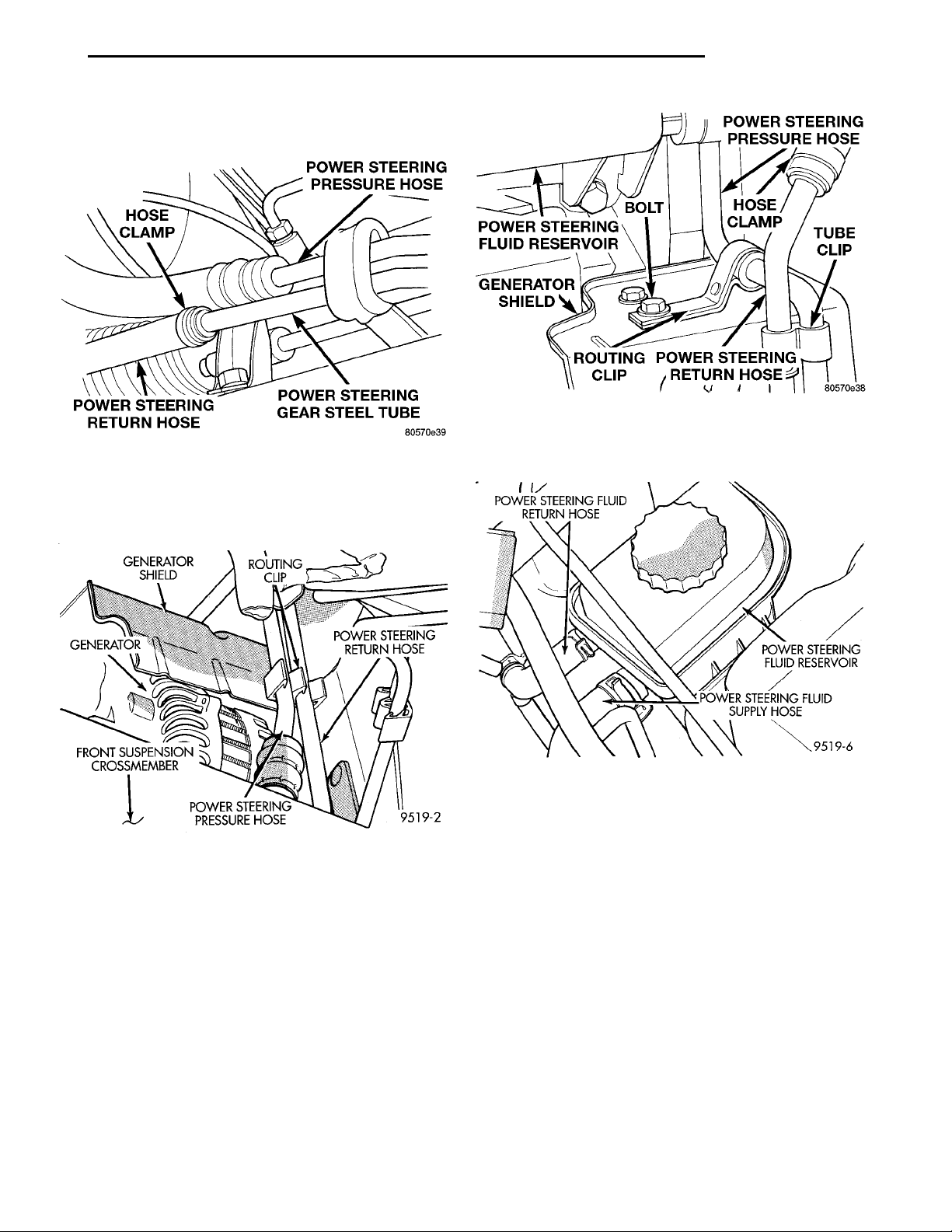
(2) Remove hose clamp, attaching return hose to
steel tube at power steering gear (Fig. 15). Let power
Page 17
GENERATOR SHIELD ROUTINGCLIP POWER STEERING RETURNHOSEPOWER STEERING PRES-SURE HOSEFRONT SUSPENSIONCROSSMEMBERGENERATOR
POWER STEERING PRES-SURE HOSEPOWER STEERING GEARSTEEL TUBEPOWER STEERING RETURNHOSEHOSECLAMP
POWER STEERING FLUID RETURNHOSE
POWER STEERING PRES-SURE HOSETUBE CLIPPOWER STEERINGRETURN HOSEROUTING CLIPGENERATORSHIELDPOWER STEERING FLUIDRESERVOIR BOLT HOSECLAMP
POWER STEERING FLUID SUPPLYHOSE
POWER STEERING FLUID
RESERVOIR
PL STEERING 19 - 17
REMOVAL AND INSTALLATION (Continued)
steering fluid, drain from return hose and power
steering fluid reservoir, until reservoir is empty.
Fig. 17 Tube Clip At Generator Shield
18). Then remove power steering return hose from
Fig. 15 Power Steering Return Hose At Steering
Gear
(3) Remove power steering return hose from routing clip on generator shield (Fig. 16).
power steering fluid reservoir.
Fig. 16 Power Steering Hose Routing Clip At
Generator Shield
(4) Lower vehicle.
(5) Remove tube clip at generator shield (Fig. 17)
attaching power steering fluid return hose to power
steering fluid pressure hose.
CAUTION: Care must be used when removing
power steering fluid return hose from power steering fluid reservoir. If excessive force is used when
trying to remove hose from nipple on power steering fluid reservoir, nipple can break off of the reservoir.
(6) Remove hose clamp, attaching power steering
return hose to power steering fluid reservoir (Fig.
Fig. 18 Power Steering Return Hose At Reservoir
(7) Remove the power steering return hose from
the vehicle. The power steering return hose is
removed from the top of the engine compartment.
INSTALL
(1) Install power steering return hose on vehicle.
Power steering return hose is installed from the top
of the vehicles engine compartment.
CAUTION: Care must be used when installing
power steering fluid return hose on power steering
fluid reservoir. If excessive force is used when trying to install hose on nipple of power steering fluid
reservoir, nipple can be broken off the reservoir.
(2) Install power steering return hose on power
steering fluid reservoir fitting. Install hose clamp on
power steering return hose at power steering fluid
reservoir (Fig. 18). Be sure hose clamp is
Page 18
POWER STEERING FLUID RETURNHOSE
POWER STEERING FLUIDSUPPLY HOSE POWER STEERINGPUMPHOSECLAMP
POWER STEERING FLUID SUPPLYHOSE
POWER STEERING FLUID
RESERVOIR
19 - 18 STEERING PL
REMOVAL AND INSTALLATION (Continued)
installed on return hose past upset bead on
power steering fluid reservoir.
(3) Raise vehicle.
(4) Clip power steering return hose and pressure
hose together (Fig. 17).
(5) Install power steering return hose on steel tube
at power steering gear (Fig. 15). Install hose clamp
on power steering return hose at power steering gear
(Fig. 15). Be sure hose clamp is installed on
return hose past upset bead on steel tube at
power gear.
(6) Install power steering return hose on routing
clip at generator shield (Fig. 16).
(7) Lower vehicle.
(8) Start the engine and let run for a few seconds.
Then turn the engine off.
(9) Add fluid if necessary. Repeat the above procedure until the fluid level remains constant after running the engine.
(10) Raise front wheels of vehicle off the ground.
(11) Start the engine. Slowly turn the steering
wheel right and left, lightly contacting the wheel
stops. Then turn the engine off.
(12) Add power steering fluid if necessary.
(13) Lower the vehicle and turn the steering wheel
slowly from lock to lock.
(14) Stop the engine. Check the fluid level and
refill as required.
(15) If the fluid is extremely foamy, allow the vehicle to stand a few minutes and repeat the above procedure.
(16) After hose is installed, check for leaks at all
hose connections.
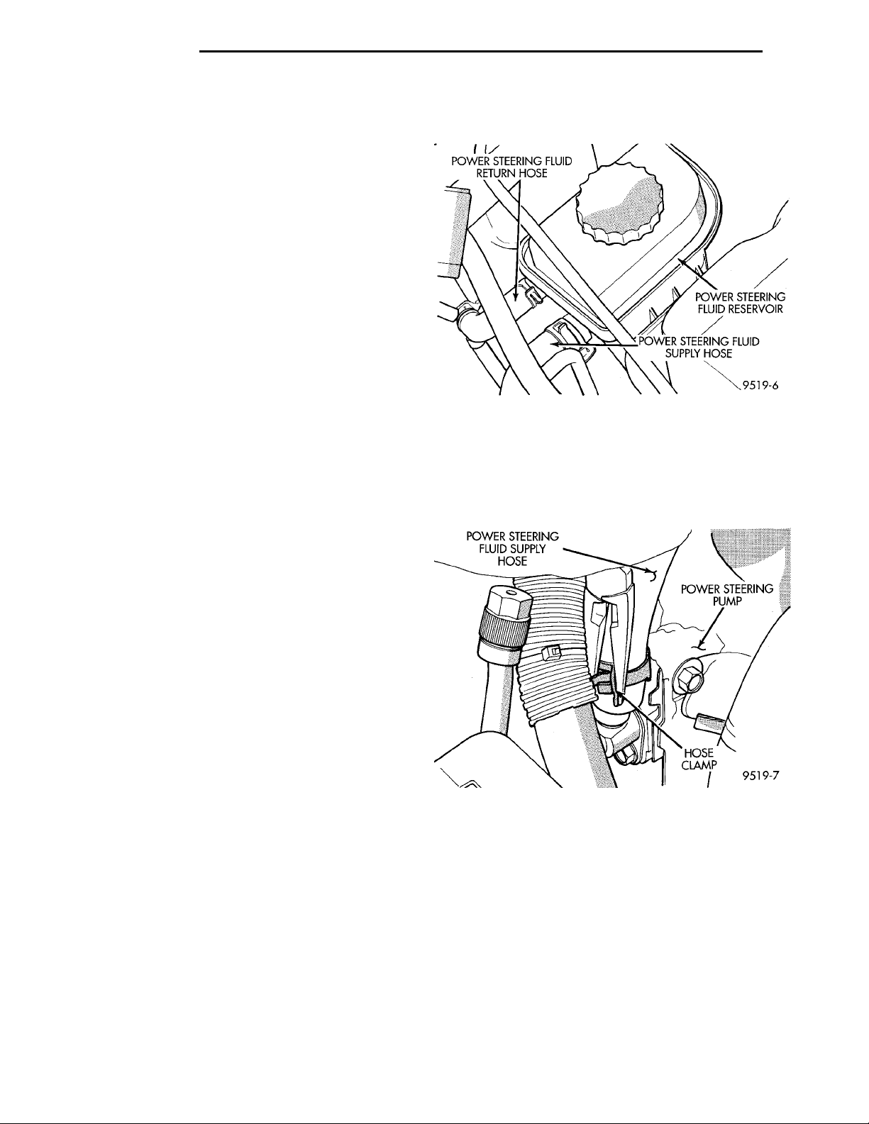
(Fig. 19). Then remove power steering fluid supply
hose from power steering fluid reservoir.
Fig. 19 Power Steering Fluid Supply Hose At
Reservoir
(2) Remove hose clamp, attaching power steering
fluid supply hose to the power steering pump (Fig.
20). Then remove power steering fluid supply hose
from power steering pump fitting.
POWER STEERING FLUID SUPPLY HOSE RESERVOIR TO POWER STEERING PUMP
WARNING: POWER STEERING OIL, ENGINE
PARTS AND EXHAUST SYSTEM MAY BE
EXTREMELY HOT IF ENGINE HAS BEEN RUNNING.
DO NOT START ENGINE WITH ANY LOOSE OR DISCONNECTED HOSES. DO NOT ALLOW HOSES TO
TOUCH HOT EXHAUST MANIFOLD OR CATALYST.
REMOVE
CAUTION: Care must be used when removing the
power steering fluid supply hose from power steering fluid reservoir. If excessive force is used when
trying to remove hose from nipple on power steering fluid reservoir, nipple can break off of the reservoir.
(1) Remove hose clamp, attaching power steering
fluid supply hose to power steering fluid reservoir
Fig. 20 Power Steering Fluid Supply Hose At Power
Steering Pump
(3) Remove power steering fluid supply hose from
engine.
INSTALL
(1) Install power steering fluid supply hose back
on engine making sure it is correctly routed.
CAUTION: Care must be used when installing
power steering fluid supply hose on power steering
fluid reservoir. If excessive force is used when trying to install hose on nipple of power steering fluid
reservoir, nipple can be broken off the reservoir.
Page 19
POWER STEER-ING PUMP POWER STEERING PRES-SURE HOSEPOWER STEER-ING PUMPBRACKET LOCATING PIN BANJO BOLT
POWER STEERING FLUIDSUPPLY HOSE POWER STEERINGPUMPHOSECLAMP
PL STEERING 19 - 19
REMOVAL AND INSTALLATION (Continued)
(2) Install power steering fluid supply hose on
power steering fluid reservoir fitting. Install hose
clamp on power steering fluid supply hose at power
steering fluid reservoir (Fig. 19). Be sure hose
clamp is installed on return hose past upset
bead on power steering fluid reservoir.
(3) Install power steering fluid supply hose on
power steering pump fitting. Install hose clamp on
power steering fluid supply hose at power steering
pump fitting (Fig. 20). Be sure hose clamp is
installed on power steering fluid supply hose
past upset bead on power steering pump fitting.
(4) Start the engine and let run for a few seconds.
Then turn the engine off.
(5) Add fluid if necessary. Repeat the above procedure until the fluid level remains constant after running the engine.
(6) Raise front wheels of vehicle off the ground.
(7) Start the engine. Slowly turn the steering
wheel right and left, lightly contacting the wheel
stops. Then turn the engine off.
(8) Add power steering fluid if necessary.
(9) Lower the vehicle and turn the steering wheel
slowly from lock to lock.
(10) Stop the engine. Check the fluid level and
refill as required.
(11) If the fluid is extremely foamy, allow the vehicle to stand a few minutes and repeat the above procedure.
(12) After hose is installed, check for leaks at all
hose connections.
Fig. 21 Power Steering Hose Attachment To Power
Steering Pump
(3) Discard all used O-rings on the power steering
pressure hose Banjo fitting and Banjo bolt.
(4) Remove hose clamp attaching power steering
fluid supply hose to the power steering pump suction
fitting (Fig. 22). Remove power steering fluid supply
hose from power steering pump fitting.
POWER STEERING PUMP (ALL ENGINES)
WARNING: POWER STEERING OIL, ENGINE COMPONENTS AND EXHAUST SYSTEM MAY BE
EXTREMELY HOT IF ENGINE HAS BEEN RUNNING.
DO NOT START ENGINE WITH ANY LOOSE OR DISCONNECTED HOSES, OR ALLOW HOSES TO
TOUCH HOT EXHAUST MANIFOLD OR CATALYST.
The power steering pump removal procedure and
pump and bracket fastener locations are the same for
both engine applications used for this vehicle. The
front power steering pump bracket must be removed
as an assembly with the power steering pump and
removed from the pump after removing the pulley
from the power steering pump.
REMOVE
(1) Remove battery cable from (-) negative post on
battery.
(2) Remove Banjo Bolt and power steering fluid
pressure hose from pressure fitting on power steering
pump (Fig. 21).
Fig. 22 Power Steering Fluid Supply Hose At Power
Steering Pump
(5) Raise vehicle on jackstands or centered on a
frame contact type hoist. See hoisting in the Lubrication And Maintenance Section of this service manual
for the required lifting procedure to be used for this
vehicle.
NOTE: If the vehicle is equipped with a dual overhead cam engine, the bolt attaching the coolant
tube to the intake manifold needs to be removed.
Refer to following step for required procedure.
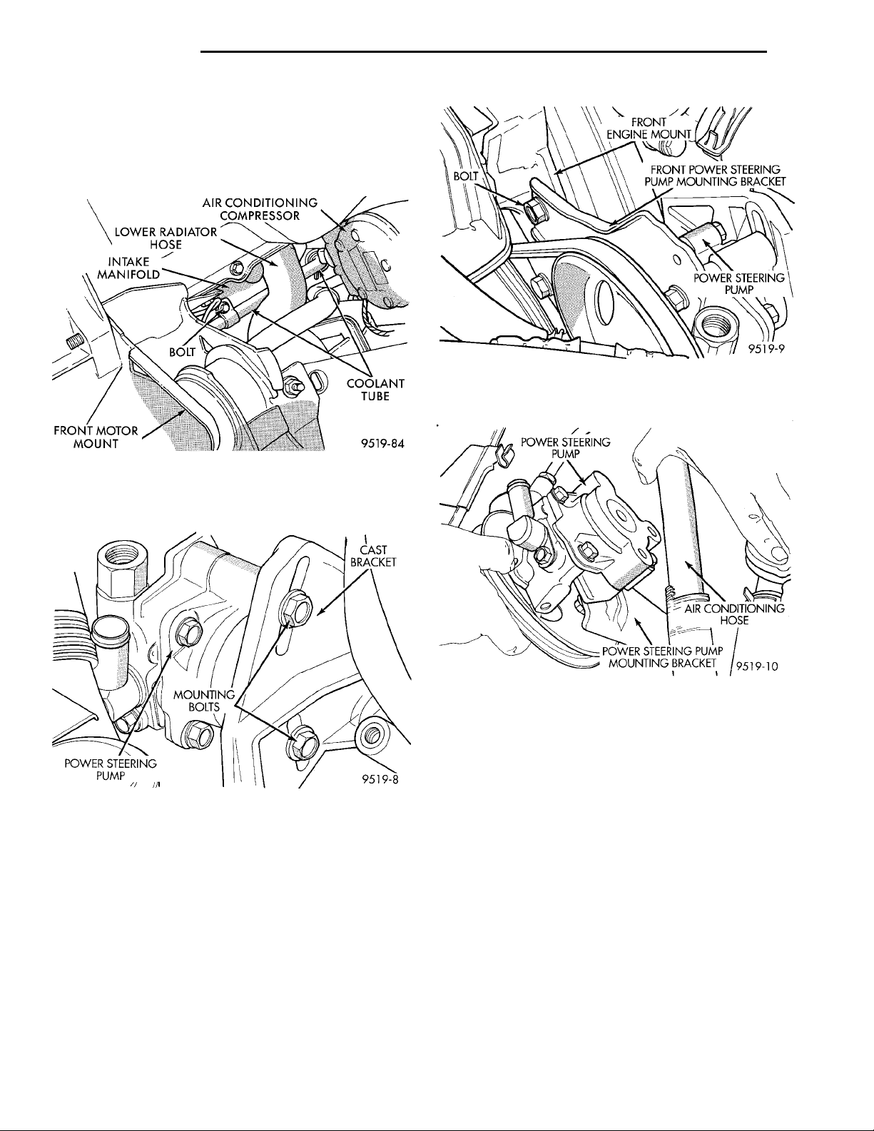
(6) Remove the bolt attaching the coolant tube
(Fig. 23) to the bottom of the intake manifold. The
Page 20
INTAKE MANIFOLDLOWER RADIATOR HOSEAIR CONDITIONING COM-PRESSOR COOLANT TUBEFRONT MOTOR MOUNT BOLT
CASTBRACKETMOUNTINGBOLTSPOWER STEER-ING PUMP
BOLT
POWER STEERING PUMP AIR CONDITIONING HOSEPOWER STEERING PUMPMOUNTING BRACKET
FRONT ENGINEMOUNT
FRONT POWER STEERING PUMP
POWER STEERING PUMP
MOUNTING BRACKET
19 - 20 STEERING PL
REMOVAL AND INSTALLATION (Continued)
bolt requires removal to allow the coolant tube
to be moved out of the way for access to the
power steering pump mounting bolt. The coolant tube does not need to be removed or the
cooling system drained.
Fig. 25 Power Steering Pump Front Mounting
Bracket Bolt
Fig. 23 Coolant Tube To Intake Manifold Attachment
(7) Remove the 2 power steering pump to cast
bracket mounting and adjustment bolts (Fig. 24).
Fig. 24 Power Steering Pump Mounting Bolts (Rear)
NOTE: The power steering pump front mounting
bracket is slotted at the bolt attaching it to the front
engine mount (Fig. 25). This bolt only needs to be
loosened to remove mounting bracket from engine.
(8) Loosen bolt (Fig. 25) attaching the power steering pump front mounting to the front engine mount
only far enough to slide the bracket out from under
the bolt.
(9) Remove power steering pump drive belt from
power steering pump pulley.
(10) Remove power steering pump and front
mounting bracket as an assembly from the engine
(Fig. 26).
Fig. 26 Power Steering Pump And Bracket
(11) Transfer required parts from removed power
steering pump to replacement power steering pump.
INSTALL
(1) Install power steering pump and mounting
bracket as an assembly (Fig. 26) back on the engine
using reverse of removal procedure.
(2) Slide front power steering pump bracket
between bracket mounting bolt and front engine
mount (Fig. 25). Be sure washer on bolt is
between the head of the bolt and bracket and
does not get trapped between bracket and
engine mount.
(3) Install the 2 power steering pump to cast
mounting bracket attaching bolts (Fig. 24). Do not
tighten bolts at this time.
(4) Install power steering pump drive belt on
power steering pump pulley.
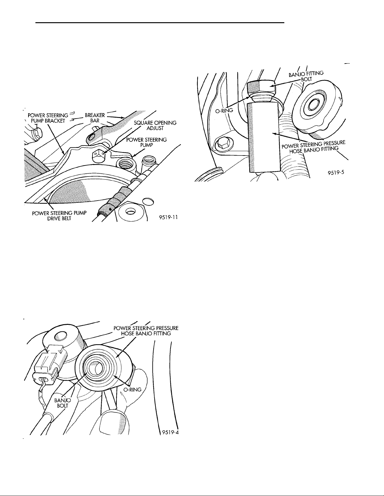
(5) Install a 1/2 in. breaker bar in the square hole
in the front power steering pump mounting bracket
(Fig. 27). Then rotate pump in to obtain the correct
Page 21
POWER STEERINGPUMP BRACKET BREAKERBAR SQUARE OPENING ADJUSTPOWER STEERING PUMPPOWER STEERING PUMPDRIVE BELT
BANJO BOLT
POWER STEERING PRESSUREHOSE BANJO FITTINGO-RING
O-RING
BANJO FITTINGBOLT
POWER STEERING PRESSURE
HOSE BANJO FITTING
PL STEERING 19 - 21
REMOVAL AND INSTALLATION (Continued)
drive belt tension. See Accessory Drive Belts in
Group 7 Cooling System of this service manual for
the correct drive belt tension specification. When correct drive belt tension is obtained torque the 2 bolts
at the power steering pump cast mounting bracket
(Fig. 24) to 54 N·m (40 ft. lbs.). Then torque the front
power steering pump mounting bracket bolt (Fig. 25)
to 54 N·m (40 ft. lbs.).
Fig. 27 Setting Power Steering Pump Drive Belt
Tension
(6) Install power steering supply hose on power
steering pump suction fitting (Fig. 22). Install hose
clamp on hose, being sure hose clamp is installed on
hose past upset bead on power steering pump tube.
(7) Using a lint free towel, wipe clean all open
power steering hose ends, and power steering pump
fittings.
(8) Install a new O-ring on the end of the power
steering pressure hose banjo fitting (Fig. 28).
Fig. 28 O-Ring Installed On Power Steering Hose
Banjo Fitting
(9) Install a new O-ring (Fig. 29) on power steering
fluid pressure hose banjo fitting bolt.
Fig. 29 O-Ring Installed On Banjo Fitting Bolt
(10) Lubricate both O-rings using fresh clean
power steering fluid.
(11) Install banjo bolt into the power steering pres-
sure hose banjo fitting.
(12) Attach power steering pressure hose on outlet
fitting of the power steering pump (Fig. 21).
(13) Position locating pin on power steering pressure hose banjo fitting so it is against power steering
pump mounting bracket (Fig. 21). While holding
locating pin against power steering pump bracket,
torque pump end Banjo bolt to 34 N·m (25 ft. lbs.).
CAUTION: Do not use automatic transmission fluid
in power steering system. Only use MoparT, Power
Steering Fluid, or equivalent.
(14) Fill power steering reservoir to correct fluid
level.
(15) Connect negative cable back on negative post
of battery.
(16) Start the engine and let run for a few seconds.
Then turn the engine off.
(17) Add fluid if necessary. Repeat the above procedure until the fluid level remains constant after
running the engine.
(18) Raise front wheels of vehicle off the ground.
(19) Start engine, then slowly turn steering wheel
right and left several times until lightly contacting
the wheel stops. Then turn the engine off.
(20) Add power steering fluid if necessary.
(21) Lower the vehicle. Start engine again and
turn the steering wheel slowly from lock to lock.
(22) Stop the engine. Check the fluid level and
refill as required.
Page 22
COOLANT RECOVERY SYS-TEM TANK
OVERFLOW HOSE FROMTHERMOSTAT HOUSING
HOSE CLAMP
POWER STEERING FLUID
POWER STEERING PRES-SURE HOSEPOWER STEERING GEARSTEEL TUBEPOWER STEERING RETURNHOSEHOSECLAMP
RIGHT FRONT STRUT
RESERVOIR
TOWER
COWLPANEL MOUNTINGSCREW
POWER STEERING FLUID RETURNHOSE
CRS
TANK
POWER STEERINGFLUID RESERVOIRMOUNTING NUT ANDSTUD
POWER STEERING FLUID SUPPLYHOSE
AIR CLEANER
POWER STEERING FLUID
ASSEMBLY
RESERVOIR
19 - 22 STEERING PL
REMOVAL AND INSTALLATION (Continued)
(23) If the fluid is extremely foamy, allow the vehicle to stand a few minutes and repeat the above procedure.
(24) After power steering pump is installed, check
for leaks at all hose connections and power steering
pump fittings.
POWER STEERING FLUID RESERVOIR
REMOVE
(1) Raise vehicle on jack stands or on a frame contact type hoist. See Hoisting in the Lubrication And
Maintenance Section of this service manual for the
required lifting procedure to be used for this vehicle.
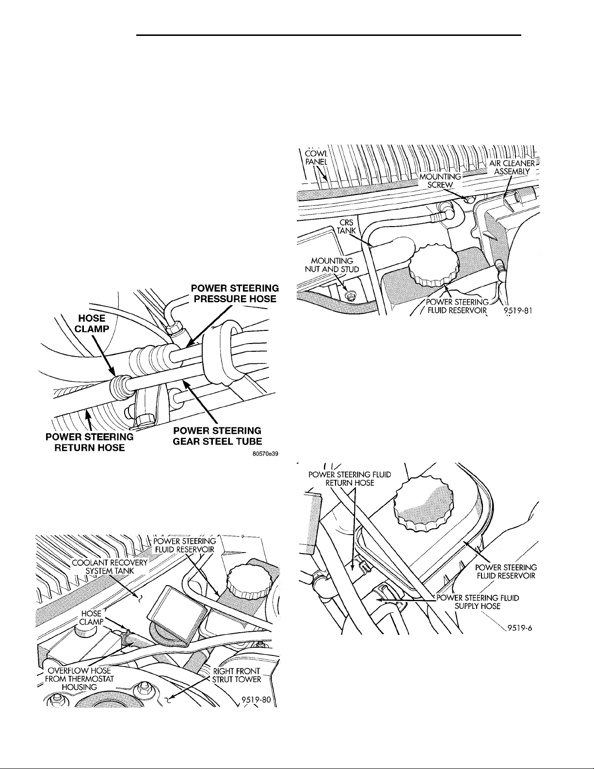
(2) Remove hose clamp, attaching return hose to
steel tube at power steering gear (Fig. 30). Let power
steering fluid drain from return hose and power
steering fluid reservoir, until reservoir is empty.
NOTE: Removal of the CRS tank improves access
to the power steering fluid reservoir attaching bolts.
(5) Remove the nut and screw attaching the CRS
tank to the dash panel (Fig. 32). Remove the CRS
tank from the dash panel and lower it down on top of
the steering gear toward the center of the vehicle.
Fig. 32 CRS Tank Mounting Bolt And Screw
CAUTION: Care must be used when removing and
installing power steering fluid hoses on the power
steering fluid reservoir. If excessive force is used
when trying to remove or install hoses on nipples
of power steering fluid reservoir, nipples can be
broken off the reservoir.
Fig. 30 Power Steering Return Hose At Steering
Gear
(3) Lower vehicle.
(4) Remove the coolant overflow hose from the
coolant recovery system (CRS) tank (Fig. 31).
(6) Remove the power steering fluid return and
supply hose from the power steering fluid reservoir
(Fig. 33).
Fig. 33 Power Steering Fluid Hoses At Reservoir
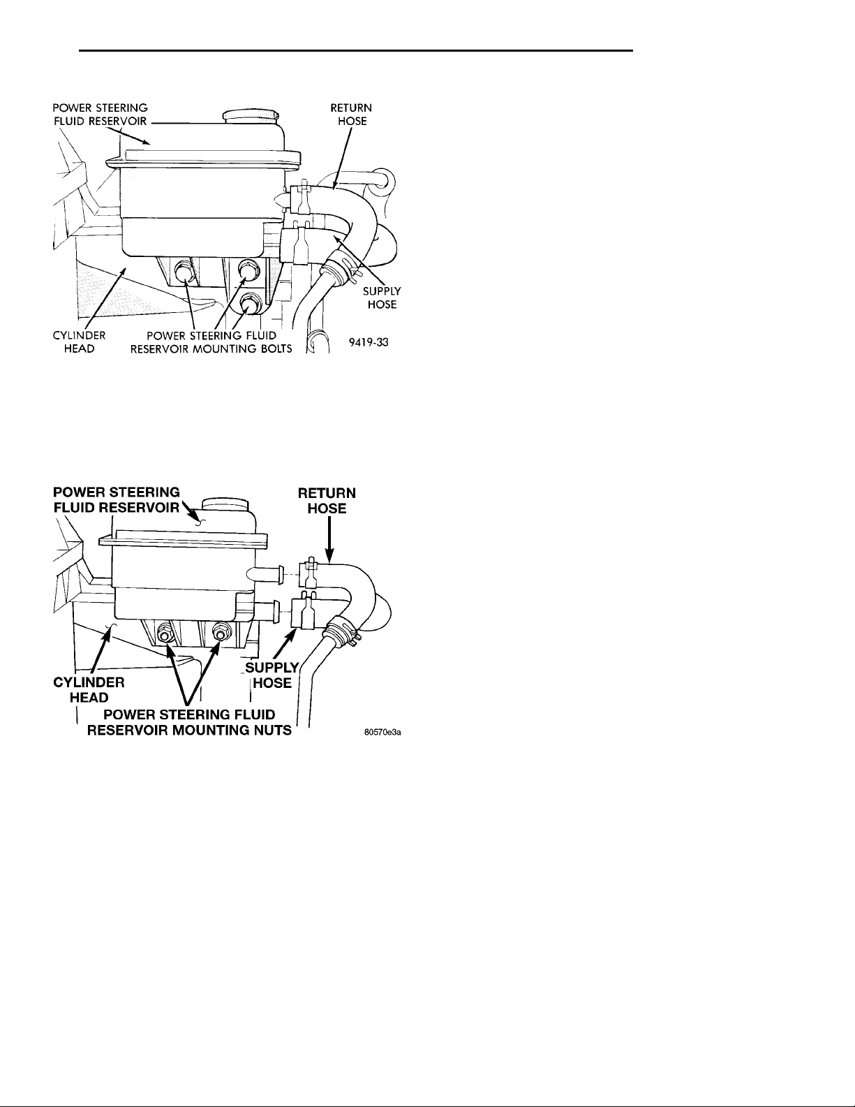
(7) If vehicle is equipped with the single
overhead cam engine, remove the 3 bolts (Fig. 34)
attaching the power steering fluid reservoir to the
cylinder head.
Fig. 31 Overflow Hose Connection At CRS Tank
Page 23
POWER STEERING FLUIDRESERVOIR RETURN HOSESUPPLY HOSEPOWER STEERING FLUID RESER-VOIR MOUNTING BOLTSCYLINDERHEAD
POWER STEERING FLUIDRESERVOIR RETURN HOSE
POWER STEERING FLUID RESER-VOIR MOUNTING NUTSCYLINDER HEAD
SUPPLY HOSE
PL STEERING 19 - 23
REMOVAL AND INSTALLATION (Continued)
(4) Install the coolant overflow hose from the coolant recovery system (CRS) tank (Fig. 31)
(5) Raise vehicle.
(6) Install power steering return hose, on the steel
tube at the power steering gear (Fig. 30). Be sure
hose clamp is installed on hose past upset bead
on power steering gear steel tube.
(7) Fill power steering pump fluid reservoir to the
proper level.
(8) Start the engine and let run for a few seconds.
Then turn the engine off.
(9) Add fluid if necessary. Repeat the above procedure until the fluid level remains constant after running the engine.
(10) Raise front wheels of vehicle off the ground.
(11) Start the engine. Slowly turn the steering
Fig. 34 Power Steering Fluid Reservoir Hoses And
Mounting
(8) If vehicle is equipped with the dual over-
head cam engine, remove the 2 nuts (Fig. 35)
attaching the power steering fluid reservoir to the
cylinder head.
wheel right and left, lightly contacting the wheel
stops. Then turn the engine off.
(12) Add power steering fluid if necessary.
(13) Lower the vehicle and turn the steering wheel
slowly from lock to lock.
(14) Stop the engine. Check the fluid level and
refill as required.
(15) If the fluid is extremely foamy, allow the vehicle to stand a few minutes and repeat the above procedure.
Fig. 35 Power Steering Fluid Reservoir Mounting
(9) Remove power steering fluid reservoir from
vehicle.
INSTALL
(1) Install power steering fluid reservoir on cylinder head. Install and securely tighten the power
steering fluid reservoir to cylinder head attaching
bolts (Fig. 34) or. (Fig. 35)
(2) Install the power steering fluid return and supply hose, on the power steering fluid reservoir fittings (Fig. 33). Be sure both hose clamps are
installed on hose past upset bead on power
steering reservoir fittings.
(3) Install engine coolant recovery system tank on
dash panel of vehicle. Install and securely tighten
attaching bolts (Fig. 32).
DISASSEMBLY AND ASSEMBLY
POWER STEERING PUMP DRIVE PULLEY
The power steering pump must be removed from
the vehicle for removal of the power steering pump
pulley. Refer to Power Steering Pump Removal in the
Power Steering Pump Service Procedures section in
this group of the service manual.
REMOVE
(1) Remove power steering pump from engine.
Refer to Power Steering Pump Removal in the Power
Steering Pump Service Procedures section in this
group of the service manual for required procedure.
CAUTION: Do not hammer on power steering
pump pulley or shaft to remove power steering
pump pulley. This will damage the pulley and the
power steering pump.
(2) Mount power steering pump in a vise using the
power steering pump mounting bracket (Fig. 36).
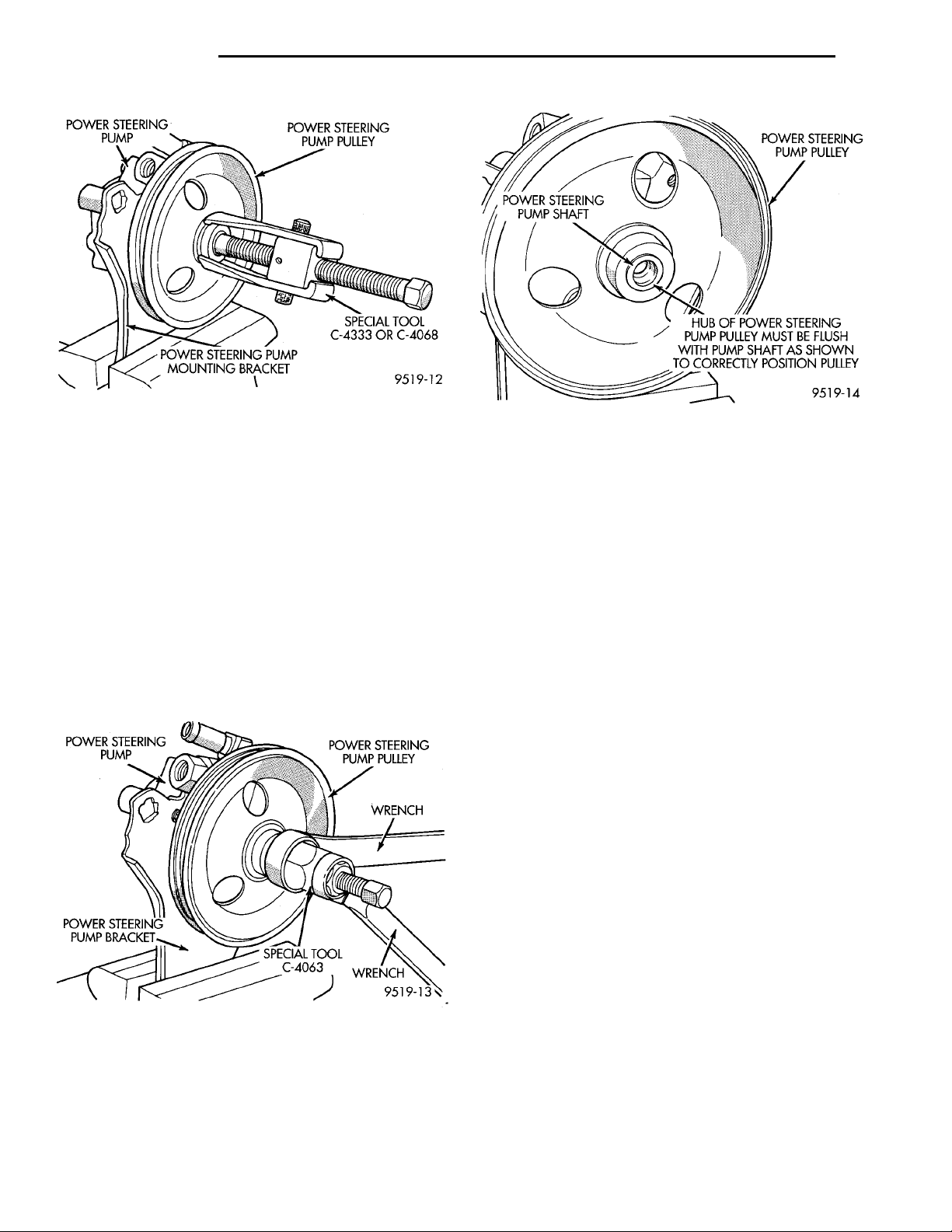
Install Puller, Special Tool C-4333 or C- 4068 on
power steering pump pulley (Fig. 36). Remove the
power steering pump pulley from the power steering
pump shaft.
(3) Replace power steering pump pulley if bent,
cracked, or loose.
Page 24
POWERSTEERINGPUMP POWER STEERING PUMP PULLEYSPECIAL TOOL C-4333 ORC-4068POWER STEERING PUMPMOUNTING BRACKET
POWER STEER-ING PUMP POWER STEER-ING PUMP PUL-LEYWRENCHWRENCHSPECIAL TOOLC-4063POWER STEERINGPUMP BRACKET
POWER STEERINGPUMP PULLEYHUB OF POWER STEERING PUMP PUL-LEY MUST BE FLUSH WITH PUMPSHAFT AS SHOWN TO CORRECTLYPOSITION PULLEYPOWER STEERING PUMPSHAFT
19 - 24 STEERING PL
DISASSEMBLY AND ASSEMBLY (Continued)
Fig. 36 Pulley Removal From Power Steering Pump
Shaft
INSTALL
CAUTION: Do not hammer on power steering
pump pulley or shaft to remove power steering
pump pulley. This will damage the pulley and the
power steering pump.
(1) Mount power steering pump in a vise using the
power steering pump mounting bracket (Fig. 37).
Then place power steering pump pulley squarely on
end of power steering pump shaft. Mount Installer,
Special Tool C-4063 in internal threads of the power
steering pump shaft and against power steering
pump pulley (Fig. 37).
Fig. 37 Pulley Installation On Power Steering Pump
Shaft
(2) Ensuring that special tool and pulley remain
aligned with pump shaft, force pulley onto power
steering pump shaft until flush with the end of the
shaft (Fig. 38). When pulley is flush with shaft
tool will no longer be able to be turned.
Fig. 38 Correctly Installed Power Steering Pump
Pulley
(3) Remove Installer, Special Tool C-4063 from
power steering pump.
(4) Install power steering pump and mounting
bracket back on engine. Refer to Power Steering
Pump Installation in the Power Steering Pump Service Procedures section in this group of the service
manual for required procedure.
POWER STEERING PUMP MOUNTING BRACKET
DISASSEMBLE
(1) Remove power steering pump from engine.
Refer to Power Steering Pump Removal And Installation in the Power Steering Pump section in this
group of the service manual for required procedure.
CAUTION: Do not hammer on power steering
pump pulley or shaft to remove power steering
pump pulley. This will damage the pulley and the
power steering pump.
(2) Mount the power steering pump in a vise using
the power steering pump mounting bracket (Fig. 39).
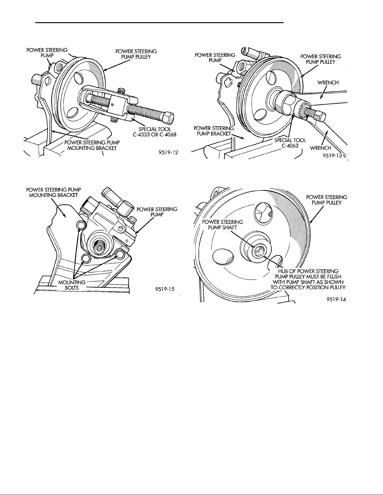
Mount Puller, Special Tool C-4333 or C- 4068 on
power steering pump pulley (Fig. 39). Remove the
power steering pump pulley from the power steering
pump shaft.
(3) Remove the 3 bolts attaching the power steering pump to the mounting bracket (Fig. 40).
(4) Remove power steering pump from mounting
bracket.
ASSEMBLE
(1) Install power steering pump on mounting
bracket. Install the 3 power steering pump mounting
bolts (Fig. 40). Torque the 3 mounting bolts to 54
N·m (40 ft. lbs.).
Page 25
POWERSTEERINGPUMP POWER STEERING PUMP PULLEYSPECIAL TOOL C-4333 ORC-4068POWER STEERING PUMPMOUNTING BRACKET
POWER STEERING PUMPMOUNTING BRACKET POWER STEER-ING PUMPMOUNTINGBOLTS
POWER STEER-ING PUMP POWER STEER-ING PUMP PUL-LEYWRENCHWRENCHSPECIAL TOOLC-4063POWER STEERINGPUMP BRACKET
POWER STEERINGPUMP PULLEYHUB OF POWER STEERING PUMP PUL-LEY MUST BE FLUSH WITH PUMPSHAFT AS SHOWN TO CORRECTLYPOSITION PULLEYPOWER STEERING PUMPSHAFT
PL STEERING 19 - 25
DISASSEMBLY AND ASSEMBLY (Continued)
Fig. 39 Pulley Removal From Power Steering Pump
Shaft
Fig. 40 Power Steering Pump Mounting Bolts
CAUTION: Do not hammer on power steering
pump pulley or shaft to remove power steering
pump pulley. This will damage the pulley and the
power steering pump.
Fig. 41 Installing Pulley On Power Steering Pump
Shaft
Fig. 42 Correctly Installed Power Steering Pump
Pulley
vice Procedures section in this group of the service
manual for required procedure.
(2) Place power steering pump pulley squarely on
end of power steering pump shaft. Mount Installer,
Special Tool C-4063 in internal threads of the power
steering pump shaft and against power steering
pump pulley (Fig. 41).
(3) Ensuring that special tool and pulley remain
aligned with pump shaft, force pulley onto power
steering pump shaft until flush with the end of the
shaft (Fig. 42). When pulley is flush with shaft
tool will no longer be able to be turned.
(4) Remove Installer, Special Tool C-4063 from
power steering pump.
(5) Install power steering pump and bracket
assembly back on engine. Refer to Power Steering
Pump Installation in the Power Steering Pump Ser-
SPECIFICATIONS
POWER STEERING PUMP FLOW SPECIFICATIONS
Power Steering Pump Flow:
At 1500 RPM And Minimum
Pressure ................4.9to5.3Liters/Min
(1.3 to 1.9 GPM)
Control Valve Pressure
Relief ....................8240 to 8920 kPa
(1195 to 1293 psi)
Page 26
19 - 26 STEERING PL
SPECIFICATIONS (Continued)
POWER STEERING PUMP FASTENER TORQUE
SPECIFICATIONS
DESCRIPTION TORQUE
Power Steering Hose:
Tube Nuts Pressure And
Return ...........................31N·m
(275 in. lbs.)
Bracket To Front Crossmember
Attaching Bolt .....................23N·m
(17 ft. lbs.).
Power Steering Pump:
Pressure Hose Banjo Bolt .....34N·m(25ft.lbs.).
Discharge Fitting ............75N·m(55ft.lbs.)
To Bracket Mounting Bolts ....54N·m(40. ft. lbs.)
Brackets To Engine Mounting
Bolts .............................54N·m
(40 ft. lbs.)
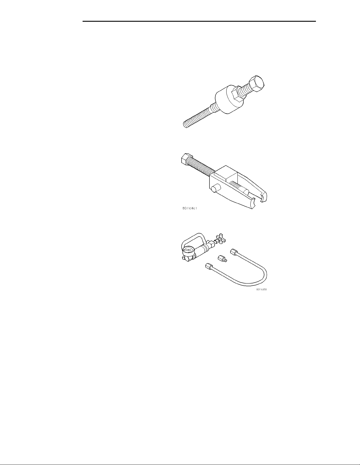
SPECIAL TOOLS
POWER STEERING PUMP
Installer C-4063B
Puller C-4333
P/S System Analyzer 6815
Page 27
TIE RODEND INNER TIE RODSTEERING GEAR BOOTSTEERING GEAR MOUNT-ING BRACKETPOWER STEERING GEARSTEERING GEAR FLUIDLINES STEERING GEAR COUPLERSTEERING GEAR BOOTINNER TIE RODTIE ROD ENDJAM NUTLOWER CONTROL ARMPOWER STEERING FLUIDHOSESFRONT SUSPENSIONCROSSMEMBERPOWER STEERING FLUIDRETURN HOSETO FLUID RESERVOIRTO POWER STEERINGPUMPPOWER STEERING FLUIDPRESSURE HOSE
PL STEERING 19 - 27
STEERING GEAR
INDEX
page page
DESCRIPTION AND OPERATION
STEERING GEAR ...................... 27
DIAGNOSIS AND TESTING
POWER STEERING SYSTEM TEST
PROCEDURE ........................ 28
REMOVAL AND INSTALLATION
MANUAL AND POWER STEERING GEAR .... 29
DESCRIPTION AND OPERATION
STEERING GEAR
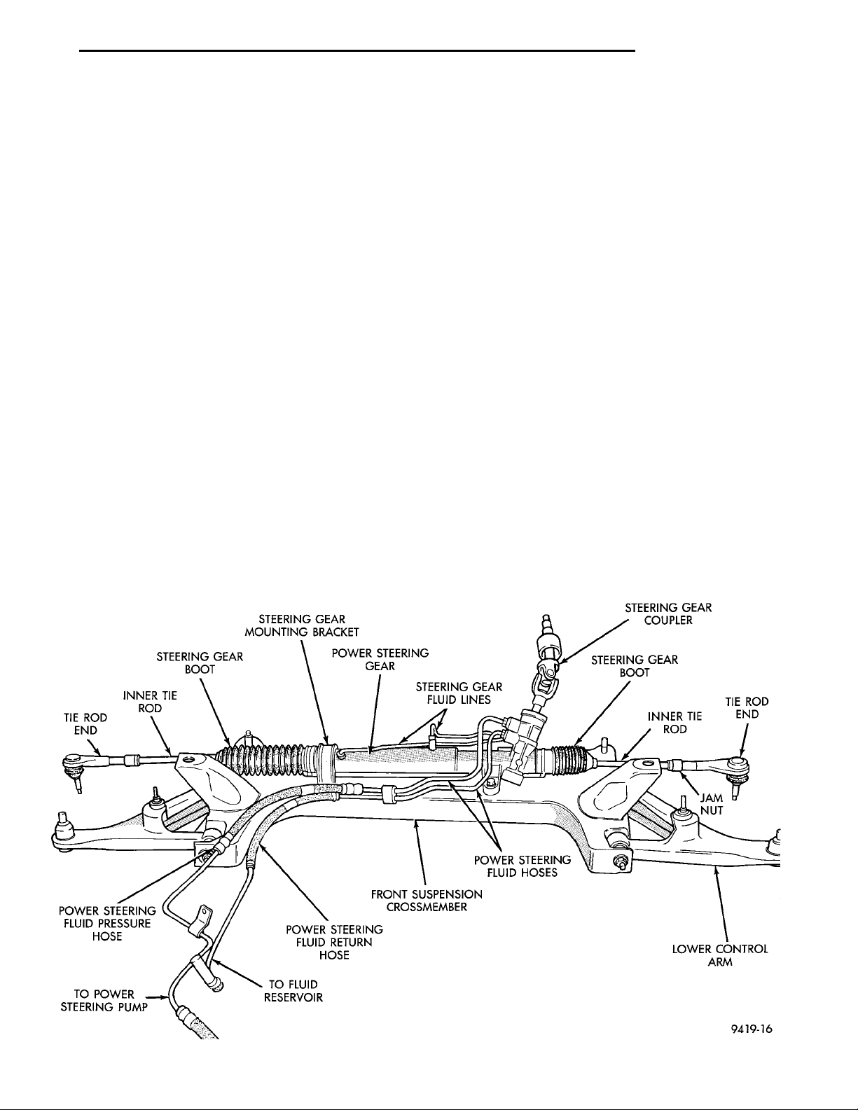
The power steering system consists of these four
major components. Power Steering Gear (Fig. 1),
Power Steering Pump, Pressure Hose, and Return
Line. Turning of the steering wheel is converted into
linear travel through the meshing of the helical pinion teeth with the rack teeth. Power assist steering is
provided by an open center, rotary type control valve
which directs oil from the pump to either side of the
integral rack piston.
DISASSEMBLY AND ASSEMBLY
OUTER TIE ROD END ................... 33
SPECIFICATIONS
STEERING GEAR FASTENER TORQUE
SPECIFICATIONS ..................... 34
SPECIAL TOOLS
POWER STEERING GEAR ................ 34
Road feel is controlled by the diameter of a torsion
bar which initially steers the vehicle. This movement
directs oil behind the integral rack piston, which, in
turn, builds up hydraulic pressure and assists in the
turning effort.
The drive tangs on the pinion of the power steering
pump mate loosely with a stub shaft. This is to permit manual steering control to be maintained if the
drive belt on the power steering pump should break.
However, under these conditions, steering effort will
be increased.
Fig. 1 Power Steering Gear Assembly
Page 28
SPECIAL TOOL6815 ADAPTER FIT-TINGS
PRESSURE HOSETO POWERSTEERING GEAR SPECIALTOOL 6815POWER STEER-ING PUMPTO POWERSTEERINGPUMP
19 - 28 STEERING PL
DESCRIPTION AND OPERATION (Continued)
NOTE: The power steering gear (Fig. 1) should NOT
be serviced or adjusted. If a malfunction or oil leak
occurs with the steering gear, the complete steering
gear needs to be replaced.
DIAGNOSIS AND TESTING
POWER STEERING SYSTEM TEST PROCEDURE
The following procedure can be used to test the
operation of the power steering system on the vehicle. This test will provide the flow rate of the power
steering pump along with the maximum relief pressure. This test is to be performed any time a power
steering system problem is present to determine if
the power steering pump or power steering gear is
not functioning properly. The following pressure and
flow test is performed using Pressure/Flow Tester,
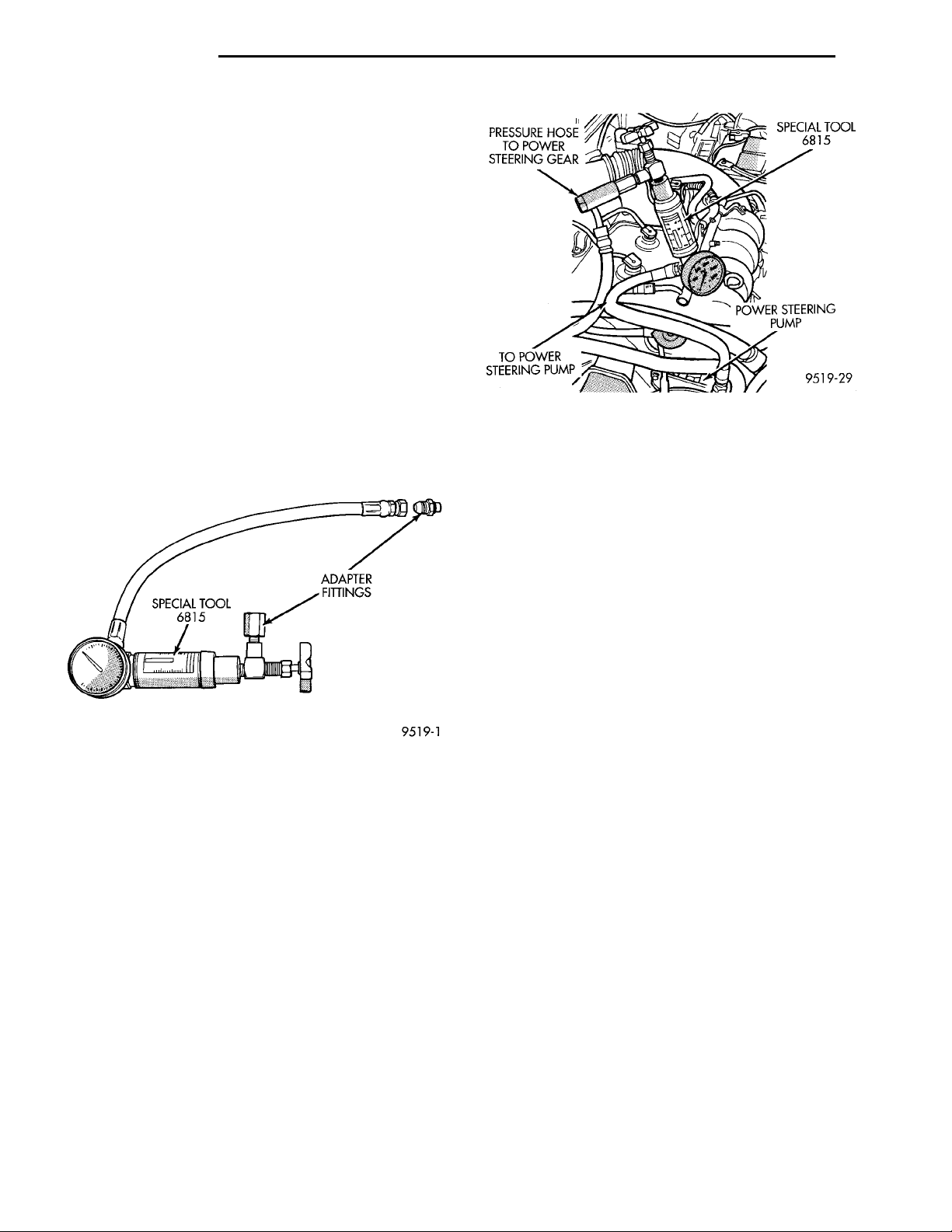
Special Tool 6815 (Fig. 2).
Fig. 3 Power Steering Pump Flow/Pressure Tester
Connected To Power Steering Pump
and repair as necessary. The initial pressure reading
should be in the range of 345-552 kPa (50-80 psi).
The flow meter should read between 1.3 and 1.4
GPM
Fig. 2 Power Steering Pump Flow/Pressure Tester
POWER STEERING PUMP FLOW AND PRESSURE TEST PROCEDURE
(1) Check power steering pump drive belt tension
and adjust as necessary.
(2) Disconnect power steering fluid pressure hose,
at power steering pump. Use a container for dripping
fluid.
(3) Connect Pressure Gauge, Special Tool from kit
6815 (Fig. 3) to both hoses using adapter fittings.
Connect spare pressure hose, to power steering pump
pressure hose banjo fitting.
(4) Completely open valve on Special Tool 6815
(Fig. 3).
(5) Start engine and let idle long enough to circulate power steering fluid through flow/pressure test
and get air out of fluid. Then shut off engine.
(6) Check power steering fluid level, and add fluid
as necessary. Start engine again and let idle.
(7) Pressure gauge should read below 862 kPa
(125 psi), if above, inspect the hoses for restrictions
CAUTION: The following test procedure involves
testing power steering pump maximum pressure
output and flow control valve operation. Do not
leave valve closed for more than 5 seconds as the
pump could be damaged.
(8) Close valve fully three times and record high-
est pressure indicated each time. All three read-
ings must be above specifications and within
345 kPa (50 psi) of each other.
NOTE: Power steering pump maximum relief pressure is 8240 to 8920 kPa (1195 to 1293 psi.).
• If power steering pump pressures above specifications but not within 345 kPa (50 psi) of each other,
then replace power steering pump.
• If pressures within 345 kPa (50 psi) of each
other but below specifications, then replace power
steering pump.
CAUTION: Do not force the pump to operate
against the stops for more than 5 seconds at a time
because, pump damage will result.
(9) Open test valve. Turn steering wheel to the
extreme left and right positions until against the
stops, recording the highest indicated pressure at
each position. Compare pressure gauge readings to
power steering pump specifications. If highest output
pressures are not the same against either stop, the
steering gear is leaking internally and must be
replaced.
Page 29
PINCH BOLTBRAKEPEDAL RETAINING PIN LOWER STEERINGCOLUMN COUPLERSTEERING COUPLERPINCH BOLT NUTSTEERING COLUMNSHAFT COUPLER
SAFETYCHAIN
TRANSAXLEBOBBLE DAMP-ENER FRONT SUSPENSIONCROSSMEMBER
STEERINGKNUCKLE TIE ROD END STUD NUT
BRAKINGDISC
TIE ROD
END
BRAKINGDISCSTEERINGKNUCKLE STUD SPECIALTOOLMB-990635
TIE ROD END
PL STEERING 19 - 29
REMOVAL AND INSTALLATION
MANUAL AND POWER STEERING GEAR
The removal and replacement procedure for both
the manual and power steering gears is the same.
The only additional steps of the procedure for the
power steering gear, is the removal and replacement
of the power steering fluid lines at the steering gear.
REMOVE
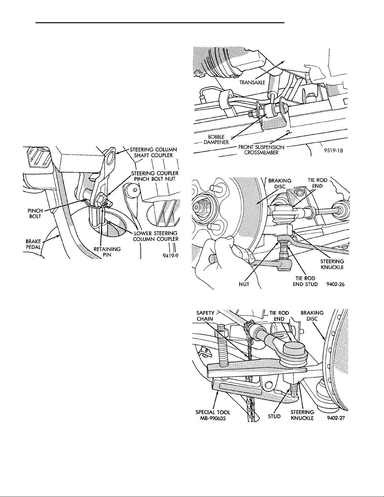
(1) From interior of vehicle, disconnect the steering gear coupler, from the steering column shaft coupler (Fig. 4).
Fig. 5 Engine/Transaxle Bobble Dampener
Fig. 4 Steering Column To Steering Gear Coupler
(2) Raise vehicle on jack stands or centered on a
frame contact type hoist. See Hoisting in the Lubrication and Maintenance section of this manual, for
the required lifting procedure to be used for this
vehicle.
(3) Remove both front wheel and tire assemblies
from the vehicle.
(4) Remove engine/transaxle bobble dampener, on
vehicles so equipped, from front suspension crossmember (Fig. 5). Bobble strut does not need to be
removed from transaxle assembly.
(5) Remove nuts attaching both outer tie rod ends
to the steering knuckles (Fig. 6). Nuts are to be
removed from tie rod ends using the following
procedure, hold tie rod end stud with an 11/32
socket, while loosening and removing nut with
wrench.
(6) Remove both tie rod end studs, from the steering knuckles, using Remover, Special Tool
MB-990635 (Fig. 7).
Fig. 6 Removing Tie Rod End Attaching Nut
Fig. 7 Tie Rod End Removal From Steering Knuckle
Page 30
STEERINGGEAR POWER STEERINGPRESSURE SWITCHPOWER STEERING FLUIDRETURN HOSEPOWER STEERINGFLUID PRESSUREHOSE
19 - 30 STEERING PL
VEHICLE WIR-ING HARNESS STEERING GEARVEHICLE WIRING HAR-NESS CONNECTOR FRONT SUSPENSIONCROSSMEMBER POWER STEERINGFLUID PRESSURESWITCH
REMOVAL AND INSTALLATION (Continued)
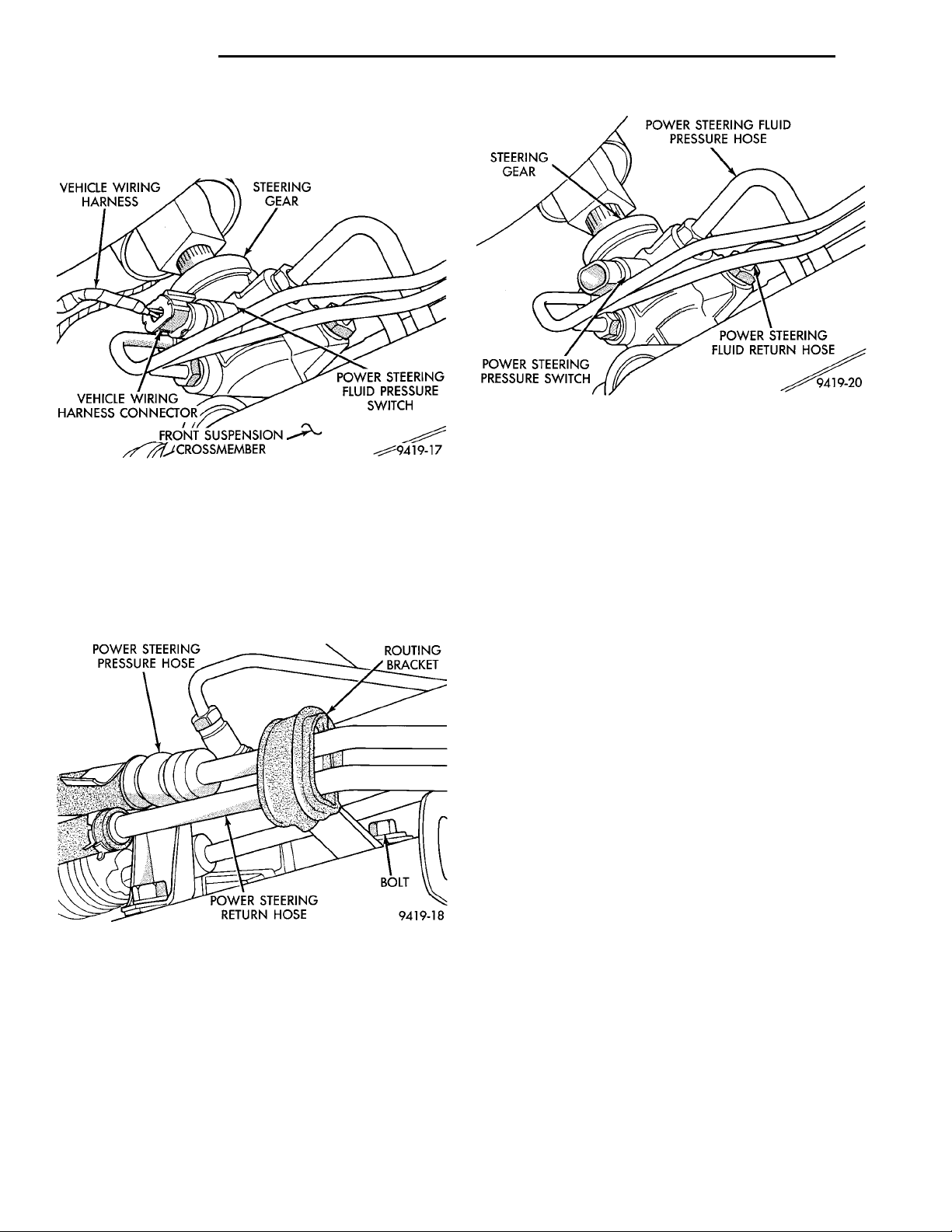
(7) If equipped, remove vehicle wiring harness connector from the power steering fluid pressure switch
(Fig. 8).
POWER STEERING PRES-SURE HOSE ROUTING BRACKETPOWER STEERING RETURNHOSE BOLT
Fig. 10 Power Steering Fluid Pressure And Return
Hoses
relation to the vehicle body. This process is carried
Fig. 8 Power Steering Fluid Pressure Switch
Electrical Connector
(8) If vehicle is equipped with power steering,
remove power steering pressure and return hose
routing bracket from front suspension crossmember
(Fig. 9). The hose routing bracket does not have
to be removed from the power steering pressure and return hoses.
out when building the vehicle, by accurately locating the front suspension crossmember, to master
gage holes located in the underbody of the vehicle.
With this method of designing and building a vehicle, it is no longer possible to adjust a vehicles
front suspension alignment settings to the required
specifications. Due to this, whenever the front suspension crossmember is removed from a vehicle, it
MUST be replaced in the same location on the body
of the vehicle it was removed from. Front suspension Toe settings though are still adjustable by the
outer tie rod ends.
Fig. 9 Power Steering Pressure And Return Hose
Routing Bracket
(9) If vehicle is equipped with power steering,
remove power steering fluid, pressure and return
hoses (Fig. 10) from the power steering gear assembly.
NOTE: This vehicle is designed and assembled
using NET BUILD front suspension alignment settings. This means that front suspension alignment
settings are determined as the vehicle is designed
by the location of front suspension components in
CAUTION: Before removing front suspension
crossmember from the vehicle, the location of the
front suspension crossmember MUST be scribbed
on body of vehicle per (Fig. 9). This must be done
so crossmember can be relocated against body of
vehicle in the same location when it is reinstalled. If
location of front suspension crossmember to body
of vehicle is not maintained when vehicle is assembled, NET BUILD front suspension alignment settings will not be obtained. This may lead to
handling and or tire wear problems.
(10) Using an awl, scribe a line (Fig. 11) marking
the location of where front suspension crossmember
is mounted against the body of the vehicle.
(11) Position a transmission jack under the center
of the front suspension crossmember (Fig. 12). Transmission jack is used to lower, support and raise front
suspension crossmember when removing steering
gear assembly.
(12) Loosen and fully remove the front 2 bolts (Fig.
13) attaching front suspension crossmember to frame
rails of vehicle. Then loosen the 2 rear bolts (Fig. 13)
Page 31
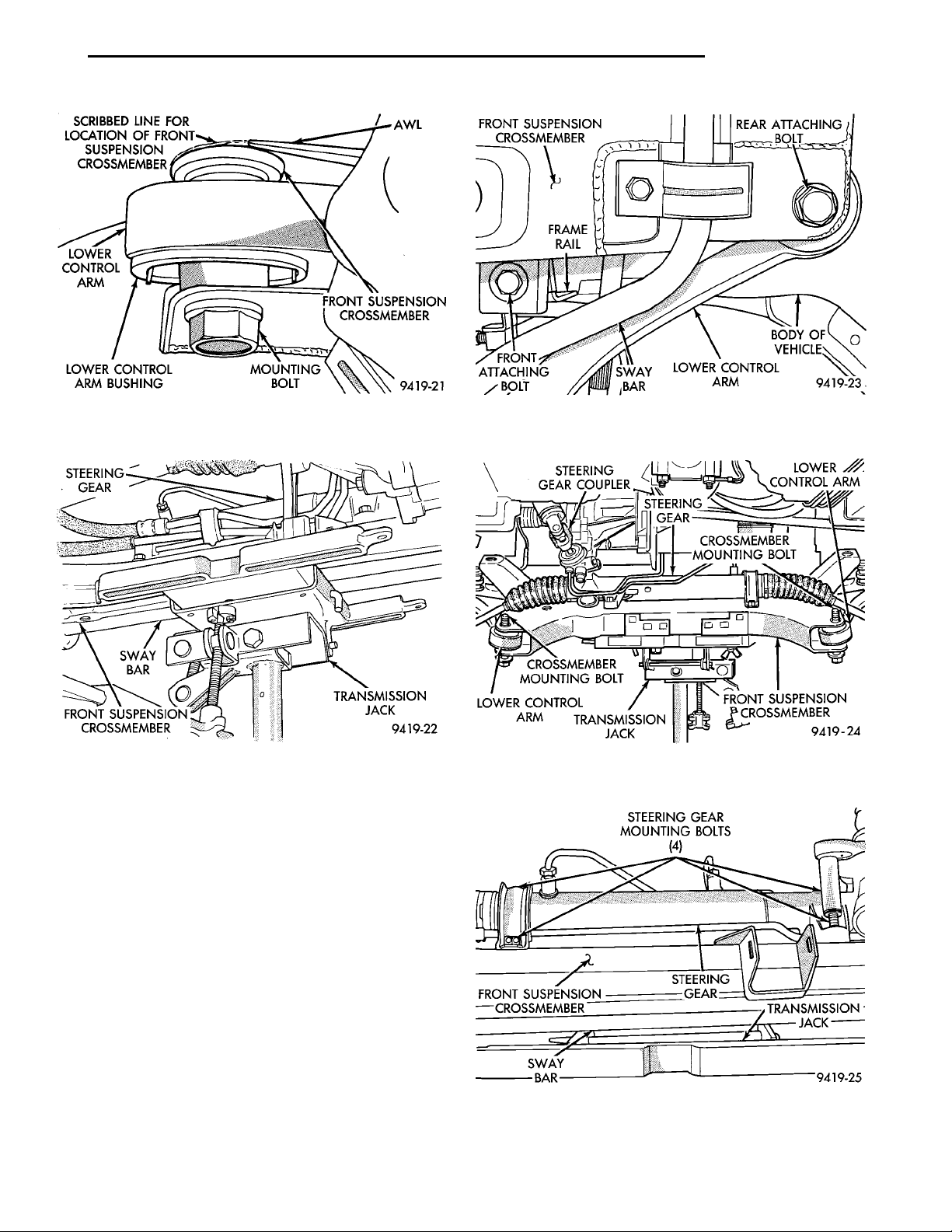
SCRIBBED LINE FOR LOCATION OFFRONT SUSPENSION CROSSMEMBERLOWER CON-TROL ARMLOWER CONTROL ARMBUSHING MOUNTINGBOLT FRONT SUSPENSIONCROSSMEMBERAWL
STEERINGGEARSWAYBARFRONT SUSPENSIONCROSSMEMBER TRANSMISSION JACK
PL STEERING 19 - 31
REMOVAL AND INSTALLATION (Continued)
Fig. 11 Marking Front Suspension Crossmember
Location
FRONT SUSPENSION
CROSSMEMBER
STEERING GEAR COUPLER
STEERING GEAR MOUNTINGBOLTS (4)
STEERING GEARSWAY BAR TRANSMISSIONJACK
STEERING
CROSSMEMBERMOUNTING BOLTCROSSMEMBERMOUNTING BOLTLOWER CONTROLARM TRANSMISSIONJACK FRONT SUSPENSIONCROSSMEMBER
GEAR
LOWER CONTROL ARM
Fig. 13 Front Suspension Crossmember Mounting
Bolts
Fig. 12 Supporting Front Suspension Crossmember
attaching front suspension crossmember and lower
control arm to body of vehicle. Lower front suspen-
sion crossmember while loosening rear bolts,
but do not remove rear bolts from crossmember.
(13) Using transmission jack, lower front suspension crossmember enough to allow steering gear to be
removed from crossmember (Fig. 14). When lower-
ing front suspension crossmember, do not let
crossmember hang from lower control arms
weight of crossmember should be supported by
transmission jack.
(14) Loosen and remove the 4 bolts (Fig. 15),
attaching steering assembly to front suspension
crossmember. Then remove the steering gear assembly from the front suspension crossmember.
(15) Transfer required parts from removed steering
gear assembly to the replacement steering gear, if a
new steering gear is being installed.
Fig. 14 Crossmember Lowered For Removal Of
Steering Gear
Fig. 15 Steering Gear Assembly Mounting Bolts
Page 32
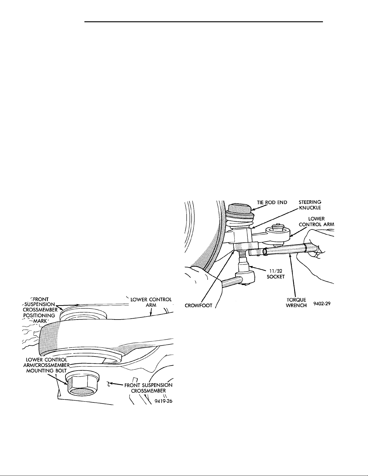
19 - 32 STEERING PL
TIE RODEND STEERINGKNUCKLELOWER CONTROLARM11/32SOCKETTORQUEWRENCH CROWFOOT
REMOVAL AND INSTALLATION (Continued)
FRONT SUSPEN-SION CROSS-MEMBERPOSITIONINGMARK LOWER CONTROLARM
LOWER CONTROL ARM/
CROSSMEMBER MOUNTING
INSTALL
BOLT
(1) Install steering gear assembly on front suspension crossmember. Install the 4 steering gear assembly to front crossmember mounting bolts (Fig. 15).
Torque the 4 steering gear mounting bolts to 68 N·m
(50 ft. lbs.).
(2) Using the transmission jack, raise front suspension crossmember and steering gear against body
and frame rails of vehicle. Start the 2 rear bolts into
tapping plates, attaching front suspension crossmember to body of vehicle (Fig. 13). Then install the 2
front bolts, attaching front suspension crossmember
to frame rails of vehicle (Fig. 13). Tighten the 4
mounting bolts, until front suspension crossmember
is against body of vehicle at the 4 mounting points.
Then torque the 4 mounting bolts to 2 N·m (20 in.
lbs.) to hold front suspension crossmember in position.
CAUTION: When front suspension crossmember is
installed back in vehicle, crossmember MUST be
aligned with positioning marks previously scribbed
into body of vehicle (Fig. 16). This MUST be done to
maintain NET BUILD front suspension alignment
settings.
FRONT SUSPENSIONCROSSMEMBER
assembly (Fig. 10). Torque power steering fluid pressure and return lines to steering gear tube nuts (Fig.
10) to 31 N·m (275 in. lbs.).
(5) If vehicle is equipped with power steering,
install power steering pressure and return hose routing bracket and attaching screw on front suspension
crossmember (Fig. 9). Torque hose routing bracket to
crossmember attaching bolt (Fig. 9) to 23 N·m (17 ft,
lbs.).
(6) If the vehicle is equipped with power steering,
install vehicle wiring harness connector onto power
steering fluid pressure switch on steering gear
assembly (Fig. 8). Be sure locking tab on wiring harness connector is securely latched to pressure switch.
(7) Install tie rod end into the steering knuckle.
Start tie rod end to steering knuckle attaching nut
onto stud of tie rod end. While holding stud of tie rod
end stationary, tighten tie rod end to steering
knuckle attaching nut (Fig. 6). Then using a crowfoot
and 11/32 socket (Fig. 17), torque tie rod end attaching nut to 55 N·m (40 ft. lbs.).
(3) Using a soft face hammer, tap front suspension
crossmember into position, until it is aligned with
the 2 previously scribbed positioning marks on body
of vehicle (Fig. 16). When front suspension crossmember is correctly positioned, torque the 2 rear
crossmember/lower control arm mounting bolts to
163 N·m (120 ft. lbs.). Then torque the 2 front crossmember to frame rail attaching bolts to 163 N·m (120
ft. lbs.) (Fig. 13).
Fig. 16 Crossmember Aligned With Positioning
Marks
(4) If vehicle is equipped with power steering,
install power steering fluid pressure and return
hoses into correct fluid ports on power steering gear
Fig. 17 Torquing Tie Rod End Attaching Nut
(8) Install engine/transaxle bobble strut (Fig. 5)
back on front suspension crossmember bracket.
Install and securely tighten the dampener to crossmember attaching bolt.
(9) Install the wheel and tire assemblies back on
vehicle. Tighten the wheel nuts to 135 N·m (100 ft.
lbs.) torque.
(10) Lower vehicle.
(11) From interior of vehicle, reconnect the steering gear coupler with the steering column shaft coupler. Install steering gear coupler retaining pinch bolt
and torque to 28 N·m (250 in. lbs.). Be sure to
install the upper to lower steering coupler
retaining bolt, retention pin (Fig. 4).
CAUTION: Do not use automatic transmission
fluid.
Page 33
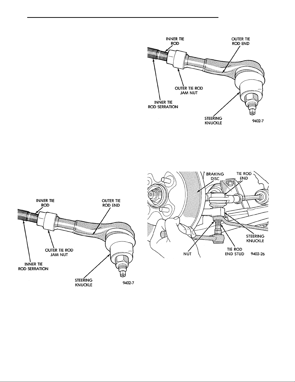
INNER TIE ROD OUTER TIE ROD ENDOUTER TIE ROD JAM NUTINNER TIE ROD SERRA-TION STEERINGKNUCKLE
PL STEERING 19 - 33
INNER TIE ROD OUTER TIE ROD ENDOUTER TIE ROD JAM NUTINNER TIE ROD SERRA-TION STEERINGKNUCKLE
BRAKINGDISC
NUT TIE ROD END STUDSTEERINGKNUCKLE
TIE ROD END
REMOVAL AND INSTALLATION (Continued)
(12) Fill power steering pump fluid reservoir to the
(Full-Cold) proper level.
(13) Start the engine and let run for a few seconds.
Then turn the engine off.
(14) Add fluid if necessary.
(15) Raise front wheels of vehicle off the ground.
(16) Start engine and turn steering wheel several
times from stop to stop to bleed air from fluid in system. Stop engine, check fluid level, and inspect system for leaks. Fill pump reservoir to correct
level with Mopart, Power Steering Fluid, or
equivalent. See Checking Fluid Level.
(17) Lower front wheels of vehicle back on the
ground.
CAUTION: During this procedure do not allow the
steering gear inner tie rod boots to become twisted.
(See Wheel Alignment in the suspension section of
this service manual).
(18) Adjust the front Toe setting on the vehicle.
Refer to the Toe Setting Procedure in Front Suspension Service Procedures in this group of the service
manual. Refer to the Specifications Section at the
end of this group for the desired front Toe specification.
(19) Tighten tie rod jam nut (Fig. 18) to 61 N·m
(45 ft.lbs.) torque.
(2) Remove the nut attaching the outer tie rod end
to steering knuckle (Fig. 20). Nut is to be removed
from tie rod end using the following procedure,
hold tie rod end stud with a 11/32 socket while
loosening and removing nut with wrench.
Fig. 19 Outer Tie Rod
Fig. 18 Outer Tie Rod End Jam Nut
(20) Adjust steering gear to tie rod boots at tie
rods.
DISASSEMBLY AND ASSEMBLY
OUTER TIE ROD END
DISASSEMBLE
(1) Loosen the inner tie rod to outer tie rod jam
nut (Fig. 19).
Fig. 20 Removing /Installing Tie Rod End Attaching
Nut
(3) Remove the tie rod end stud from steering
knuckle arm, using Remover, Special Tool
MB-990635 (Fig. 21).
(4) Remove the outer tie rod end from the inner tie
rod by un-threading it from the inner tie rod.
ASSEMBLE
(1) Install outer tie rod onto inner tie rod. Make
sure jam nut is on inner tie rod (Fig. 19).
(2) Do not tighten jam nut.
(3) Install the tie rod end into the steering
knuckle. Start tie rod end to steering knuckle attaching nut onto stud of tie rod end. While holding stud
of tie rod end stationary, tighten tie rod end to steer-
Page 34
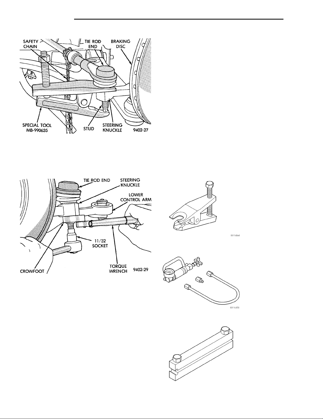
SAFETYCHAIN
TIE RODEND STEERINGKNUCKLELOWER CONTROLARM11/32SOCKETCROWFOOT TORQUEWRENCH
TIE ROD
END
BRAKINGDISCSPECIAL TOOLMB-990635 STUD STEERINGKNUCKLE
19 - 34 STEERING PL
DISASSEMBLY AND ASSEMBLY (Continued)
SPECIFICATIONS
STEERING GEAR FASTENER TORQUE SPECIFICATIONS
DESCRIPTION TORQUE
FRONT SUSPENSION CROSSMEMBER:
To Body Mounting Bolts .....163N·m(120 ft. lbs.)
STEERING GEAR:
To Crossmember Mounting Bolts . 68 N·m (50 ft. lbs.)
OUTER TIE ROD:
To Steering Knuckle Nut ......55N·m(40ft.lbs.)
To Inner Tie Rod Jam Nut .....61N·m(45ft.lbs.)
POWER STEERING HOSE:
Tube Nuts ................31N·m(275 in. lbs.)
Fig. 21 Tie Rod End Removal From Steering
Knuckle
ing knuckle attaching nut (Fig. 20). Then using a
crowfoot and 11/32 socket (Fig. 22), torque the tie rod
end attaching nut to 61 N·m (45 ft. lbs.).
Routing Bracket At
Crossmember .............23N·m(17ft.lbs.)
SPECIAL TOOLS
POWER STEERING GEAR
Fig. 22 Torquing Tie Rod End Attaching Nut
CAUTION: During this procedure do not allow the
steering gear boot to become twisted. (See Wheel
Alignment in the suspension section of this service
manual).
(4) Adjust the front Toe setting on the vehicle.
Refer to the Toe Setting Procedure in Front Suspension Service Procedures in this group of the service
manual. Refer to the Specifications Section at the
end of this group for the desired front Toe specification.
(5) Torque the tie rod jam nut (Fig. 19) to a torque
of 55 N·m (40 ft. lbs.) torque.
(6) Adjust the steering gear to inner tie rod boots
at inner tie rod if they became twisted during Toe
adjustment.
Remover Tie Rod End MB–990635
P/S System Analyzer 6815
Installer Boot Clamp C-4975A
Page 35

PL STEERING 19 - 35
STEERING COLUMN
INDEX
page page
DESCRIPTION AND OPERATION
STEERING COLUMN ASSEMBLY ........... 35
STEERING GEAR TO STEERING COLUMN
COUPLING .......................... 37
DIAGNOSIS AND TESTING
STEERING COLUMN TO STEERING GEAR
COUPLING .......................... 37
STEERING COLUMN .................... 37
DESCRIPTION AND OPERATION
STEERING COLUMN ASSEMBLY
Both the standard non-tilt and tilt steering columns (Fig. 1) have been designed to be serviced only
as complete assemblies, if a component of the steering column is defective. The only replaceable components of the steering column assembly, are the key
REMOVAL AND INSTALLATION
STEERING COLUMN SERVICE PROCEDURE
WARNINGS .......................... 38
STEERING COLUMN .................... 38
SPECIFICATIONS
STEERING COLUMN FASTENER TORQUE
SPECIFICATIONS ..................... 43
cylinder, ignition switch, multi- function switch, clock
spring, trim shrouds and steering wheel. These
replaceable components of the steering column can be
serviced without requiring removal of the steering
column from the vehicle.
Page 36
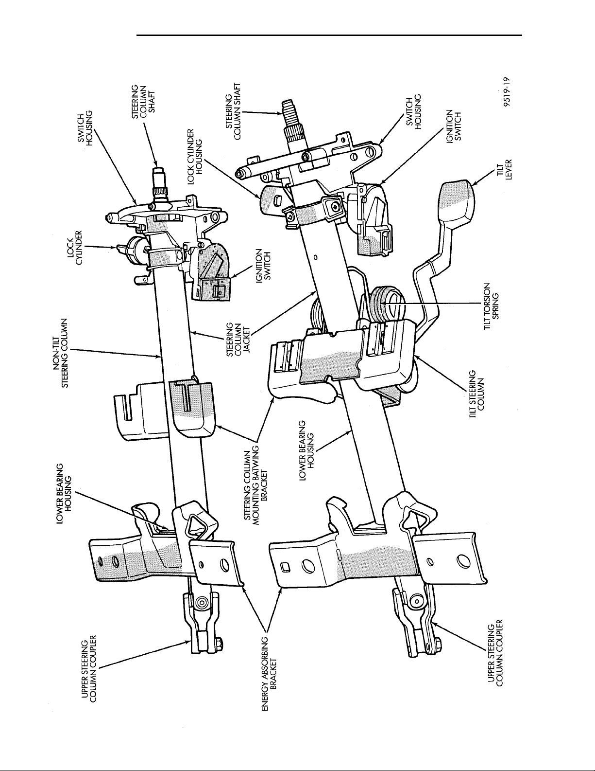
19 - 36 STEERING PL
DESCRIPTION AND OPERATION (Continued)
Fig. 1 Non-Tilt And Tilt Steering Column Assemblies
Page 37
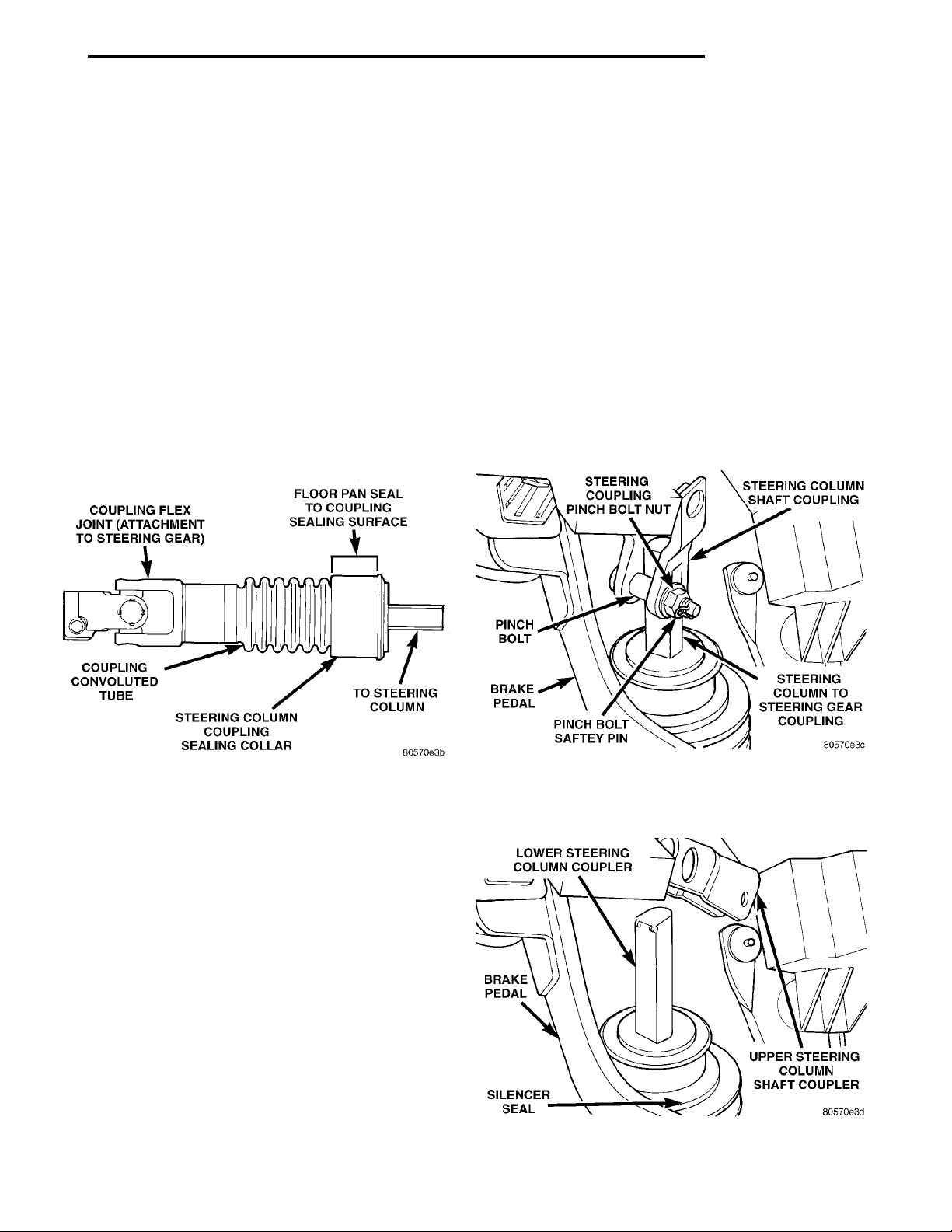
COUPLING FLEX JOINT(ATTACHMENT TO STEER-ING GEAR) FLOOR PAN SEAL TO COU-PLING SEALING SURFACETO STEERINGCOLUMNSTEERING COLUMN COU-PLING SEALING COLLARCOUPLING CONVO-LUTED TUBE
LOWER STEERING COLUMNCOUPLER UPPER STEERING COL-UMN SHAFT COUPLERSILENCER SEALBRAKEPEDAL
STEERING COUPLINGPINCH BOLT NUT STEERING COLUMNSHAFT COUPLINGSTEERING COL-UMN TO STEER-ING GEARCOUPLINGPINCH BOLT SAFETY PINBRAKEPEDALPINCHBOLT
PL STEERING 19 - 37
DESCRIPTION AND OPERATION (Continued)
STEERING GEAR TO STEERING COLUMN COUPLING
This vehicle uses a differently designed coupling
for connecting the steering column to the steering
gear (Fig. 2).
This coupling (Fig. 2) is different in its appearance
and in the way it functions than the previous coupling used on this vehicle and couplings used on
other Chrysler vehicles. This coupling functions by
bending at the bellows section (Fig. 2) of the coupling
on impact, where as the previous coupling separated
at its detachable joint on an impact.
This coupling incorporates a hollow convoluted
tube (Fig. 2) which allows the coupling to bend as
required when a vehicle is involved in a collision. The
previous coupling used on this vehicle incorporated 2
release washers which allowed the coupling to separate into 2 pieces, if necessary, when a vehicle was
involved in a collision.
(2) If a vehicle is involved in an impact of the vehicles front suspension or under carriage, which results
in any type of damage to the front suspension crossmember.
(3) Under any conditions which result in the steering column assembly or steering column shaft receiving a force great enough to move the steering column
or shaft forward or rearward in a vehicle.
STEERING COUPLING INSPECTION PROCEDURE
(1) Remove the pinch bolt safety pin from the
steering column shaft coupling pinch bolt (Fig. 3).
(2) Loosen the coupling pinch bolt retaining nut
and remove pinch bolt (Fig. 3) from steering coupler.
(Pinch bolt nut is caged to coupler and is not
removable.) Then separate the steering column
shaft coupling from the steering column to steering
gear coupling.
Fig. 2 Steering Column Coupler
DIAGNOSIS AND TESTING
STEERING COLUMN
For diagnosis of conditions relating to the steering
column, refer to the steering system diagnosis charts,
in the diagnosis and testing section at the beginning
of this group.
STEERING COLUMN TO STEERING GEAR COUPLING
STEERING COLUMN COUPLING INSPECTION
The steering column coupling MUST be inspected
whenever a vehicle is involved in an impact or whenever any of the following conditions exist.
(1) The steering column coupling must be
inspected whenever a vehicle is involved in a collision which deploys the air bag, regardless of the
extent of damage done to the vehicle.
Fig. 3 Steering Column To Coupling Attachment
(3) Remove the silencer seal (Fig. 4) enclosing the
steering column coupling.
Fig. 4 Steering Column Coupling Seal
Page 38
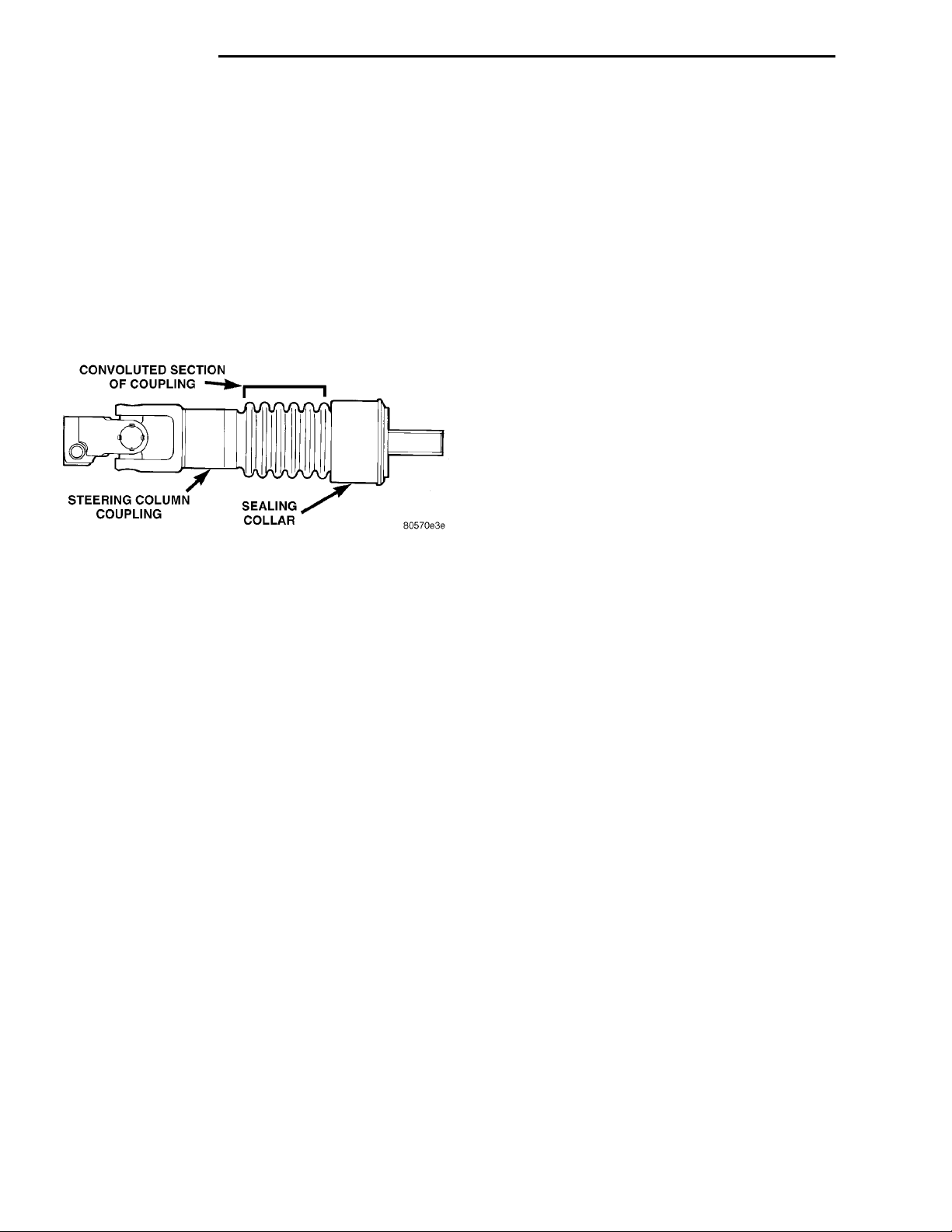
CONVOLUTED SECTION OFCOUPLING SEALING COLLARSTEERING COLUMN COU-PLING
19 - 38 STEERING PL
DIAGNOSIS AND TESTING (Continued)
(4) Inspect steering column coupling in the following areas for signs of damage:
Inspect the sealing collar on the steering column
•
coupling (Fig. 5) to ensure the it is not cracked, broken,
or otherwise damaged requiring coupling replacement.
• Inspect the convoluted section (Fig. 5) of the
steering column coupling for the following conditions
or any other visible signs of damage.
• Uneven spacing between the convolutes on the
coupling.
• Dings or dents in the convolutes of the cou-
pling or anywhere else on the coupling wall.
A bend in the convoluted section of the coupling.
•
Fig. 5 Steering Column Coupling Inspection
If any of the preceding conditions exist the steering
coupling MUST be replaced.
The steering gear must be removed from the vehicle to allow access for replacement of the steering
coupling. Refer to Steering Gear Service Procedures
in this group of the service manual for the required
steering gear removal procedure.
(5) If steering coupling does not require replacement, install steering column coupling silencer seal
(Fig. 4) back on vehicle.
(6) Ensure front wheels of vehicle are positioned
straight-ahead and then align and attach steering
column to steering coupling (Fig. 3). Install the coupling pinch bolt (Fig. 3). Tighten the pinch bolt nut
to a torque of 28 N·m (250 in. lbs.). Be sure to
install upper to lower steering coupling pinch
bolt safety pin (Fig. 3).
REMOVAL AND INSTALLATION
STEERING COLUMN SERVICE PROCEDURE WARNINGS
WARNING: BEFORE BEGINNING ANY SERVICE PROCEDURES THAT INVOLVES REMOVING THE AIR BAG.
REMOVE AND ISOLATE THE NEGATIVE (-) BATTERY
CABLE (GROUND) FROM THE VEHICLE BATTERY.
THIS IS THE ONLY SURE WAY TO DISABLE THE AIR
BAG SYSTEM. FAILURE TO DO THIS COULD RESULT
IN ACCIDENTAL AIR BAG DEPLOYMENT AND POSSIBLE PERSONAL INJURY.
WARNING: THE AIR BAG SYSTEM IS A SENSITIVE,
COMPLEX ELECTRO-MECHANICAL UNIT. BEFORE
ATTEMPTING TO DIAGNOSE, REMOVE OR INSTALL
THE AIR BAG SYSTEM COMPONENTS YOU MUST
FIRST DISCONNECT AND ISOLATE THE BATTERY
NEGATIVE (GROUND) CABLE. FAILURE TO DO SO
COULD RESULT IN ACCIDENTAL DEPLOYMENT OF
THE AIR BAG AND POSSIBLE PERSONAL INJURY.
THE FASTENERS, SCREWS, AND BOLTS, ORIGINALLY USED FOR THE AIR BAG COMPONENTS,
HAVE SPECIAL COATINGS AND ARE SPECIFICALLY DESIGNED FOR THE AIR BAG SYSTEM.
THEY MUST NEVER BE REPLACED WITH ANY SUBSTITUTES. ANYTIME A NEW FASTENER IS
NEEDED, REPLACE WITH THE CORRECT FASTENERS PROVIDED IN THE SERVICE PACKAGE OR
FASTENERS LISTED IN THE PARTS BOOKS.
BEFORE SERVICING A STEERING COLUMN
EQUIPPED WITH AN AIR BAG, REFER TO GROUP
8M, ELECTRICAL FOR PROPER AND SAFE SERVICE PROCEDURES.
NOTE: Safety goggles should be worn at all times
when working on steering columns.
CAUTION: Disconnect negative (ground) cable
from the battery, before servicing any column component.
CAUTION: Do not attempt to remove the pivot pins
to disassemble the tilting mechanism. Damage will
occur.
STEERING COLUMN
REMOVE
(1) Disconnect the negative (ground) cable from
the battery and isolate cable.
(2) Before beginning removal of steering column
assembly from vehicle, be sure front wheels of vehicle
are in the straight ahead position.
(3) Remove the 4 screws attaching steering column
cover, to lower instrument panel. Then remove the
trim panel from the instrument panel (Fig. 6).
(4) Remove 3 screws (Fig. 7) attaching the steering
column cover liner to the instrument panel. Remove
the liner from the lower instrument panel.
(5) If vehicle is equipped with speed control,
remove the speed control switches from the steering
wheel (Fig. 8). If vehicle is not equipped with speed
control, remove the trim covers from the sides of the
steering wheel.
Page 39
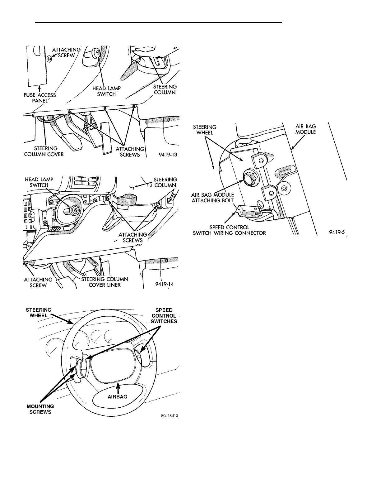
HEAD LAMPSWITCH ATTACHINGSCREWSSTEERING COLUMN COVERLINERATTACHINGSCREW STEERINGCOLUMN
ATTACHINGSCREWFUSE ACCESSPANEL HEAD LAMPSWITCH STEERINGCOLUMNSTEERING COLUMNCOVER ATTACHINGSCREWS
STEERING WHEELSPEED CONTROLSWITCHESAIRBAGMOUNTING SCREWS
PL STEERING 19 - 39
REMOVAL AND INSTALLATION (Continued)
Fig. 6 Steering Column Cover
STEERINGWHEEL AIRBAG MOD-ULEAIRBAG MODULEATTACHING BOLTSPEED CONTROL SWITCH WIRINGCONNECTOR
WARNING: WHEN AN UNDEPLOYED AIR BAG
ASSEMBLY IS TO BE REMOVED FROM THE STEERING WHEEL, DISCONNECT BATTERY GROUND CABLE
AND ISOLATE. ALLOW SYSTEM CAPACITOR TO DISCHARGE FOR TWO MINUTES, THEN BEGIN AIR BAG
REMOVAL.
(6) Remove the 2 fasteners, 1 on each side of steering wheel, attaching the air bag module to the steering wheel (Fig. 9).
Fig. 7 Steering Column Cover Liner
Fig. 9 Air Bag Module Mounting Bolts
WARNING: WHEN HANDLING AN UNDEPLOYED
AIR BAG MODULE DURING SERVICING OF THE
STEERING COLUMN THE FOLLOWING PRECAUTIONS SHOULD BE OBSERVED. AT NO TIME
SHOULD ANY SOURCE OF ELECTRICITY BE PERMITTED NEAR THE INFLATOR ON THE BACK OF
THE AIR BAG MODULE. WHEN CARRYING A LIVE
MODULE, THE TRIM COVER SHOULD BE POINTED
AWAY FROM THE BODY TO MINIMIZE INJURY IF
MODULE ACCIDENTLY DEPLOYS. IF AIR BAG MODULE IS PLACED ON A BENCH OR OTHER SURFACE, PLASTIC COVER SHOULD BE FACE UP TO
MINIMIZE MOVEMENT IN CASE OF ACCIDENTAL
DEPLOYMENT.
Fig. 8 Speed Control Switches
Page 40
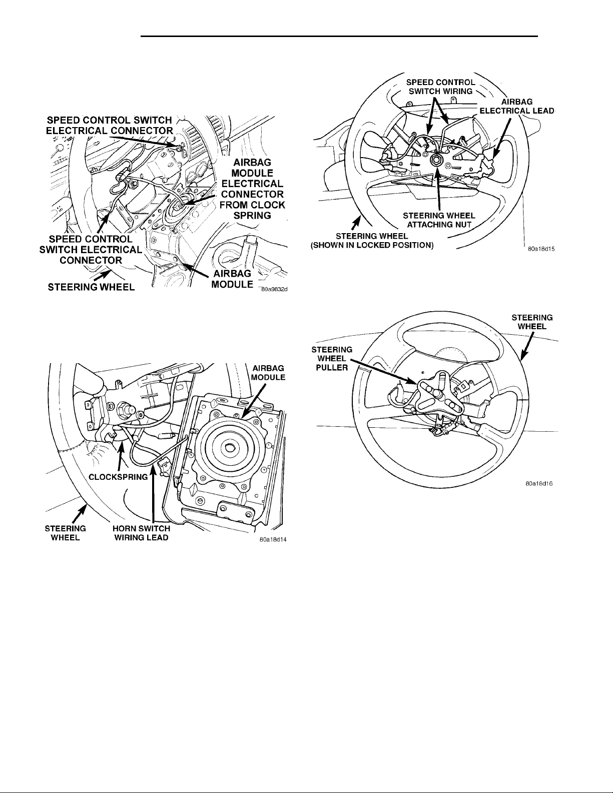
19 - 40 STEERING PL
SPEED CONTROL SWITCHELECTRICAL CONNECTORAIRBAG MODULE ELECTRI-CAL CONNECTOR FROMCLOCK SPRINGAIRBAG MODULESTEERING WHEELSPEED CONTROL SWITCHELECTRICAL CONNECTOR
REMOVAL AND INSTALLATION (Continued)
(7) Remove air bag module from center of steering
wheel. Then disconnect the clock spring electrical
lead from the back of the air bag module (Fig. 10).
in the airbag module from the wiring lead coming
from the clockspring (Fig. 11).
AIRBAG MODULEHORN SWITCH WIRINGLEADSTEERING WHEELCLOCKSPRING
STEERING WHEEL PULLERSTEERING WHEEL
Fig. 12 Steering Wheel Attaching Nut
(12) Install Puller, Snap-On CJ2001P or an equiv-
alent on the steering wheel (Fig. 13).
Fig. 10 Air Bag Module Electrical Connection
(8) Disconnect the wiring lead for the horn switch
Fig. 11 Clock Spring To Horn Switch Wiring
Connection
(9) Turn the lock cylinder to the off position and
remove the key from the lock cylinder
(10) Turn the steering wheel to the left 1/2 a turn
(180°) until the steering column lock is engaged (Fig.
12).
(11) Remove the steering wheel retaining nut,
from the steering column shaft (Fig. 12).
CAUTION: When installing Puller, Special Tool
C-3428-B on steering wheel be sure puller bolts are
fully seated in threaded puller holes on steering
wheel. If bolts are not fully seated in threaded
holes, threads may be stripped out when puller is
tightened to remove steering wheel.
Fig. 13 Steering Wheel Puller Installed
CAUTION: Do not bump or hammer on steering
wheel or steering column shaft when removing
steering wheel from steering column.
(13) Remove steering wheel assembly from steering column shaft using Puller, Special Tool C-3428-B
or equivalent.
(14) Remove key lock cylinder from steering column. Key lock cylinder is removed from steering column using the following procedure. Place the key
lock cylinder in the Run position. Then through the
hole in lower shroud, (Fig. 14) depress lock cylinder
retaining tab and remove key lock cylinder.
(15) Remove the 3 screws attaching the upper and
lower shroud to the steering column (Fig. 15). First
remove lower shroud from steering column, then
release tilt lever and tilt steering column to its lowest point. Then remove upper shroud from steering
column.
Page 41
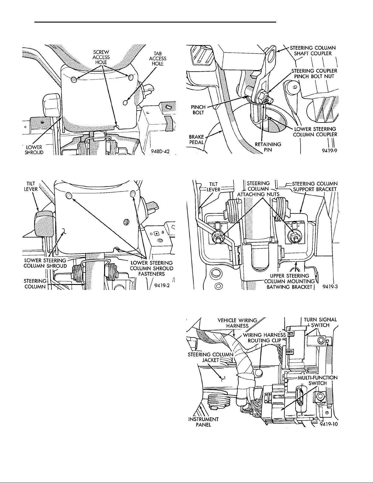
PL STEERING 19 - 41
REMOVAL AND INSTALLATION (Continued)
STEERINGCOLUMN LOWER STEERING COL-UMN SHROUD FASTEN-ERS
TILT
LOWER STEERING COL-
LEVER
UMN SHROUD
Fig. 14 Key Lock Cylinder Access Hole In Steering
Column Shrouds
STEERING COLUMN
JACKET
TILT LEVER STEERING
VEHICLE WIR-ING HARNESS
WIRING HARNESS
ROUTING CLIP
COLUMN
ATTACHING
NUTS
TURN SIGNALSWITCH
MULTI-FUNCTIONSWITCHINSTRUMENT PANEL
STEERING COLUMNSUPPORT BRACKETUPPER STEERING COLUMNMOUNTING BATWINGBRACKET
Fig. 16 Upper To Lower Steering Column Coupler
Disassembly
Fig. 15 Upper And Lower Steering Column Shrouds
(16) Remove retaining pin in the upper to lower
steering column coupler pinch bolt (Fig. 16).
(17) Loosen the upper to lower steering coupler
pinch bolt retaining nut and remove pinch bolt (Fig.
16) from steering coupler. (Pinch bolt nut is caged
to coupler and is not removable.) Then separate
upper steering coupler from lower steering coupler
shaft.
(18) Remove the 4 nuts attaching the lower
mounting bracket of the steering column to the boby
mounting bracket for the steeing column.
(19) Remove the 2 steering column assembly upper
bat wing bracket to support bracket nuts (Fig. 17).
(20) Lower steering column assembly in the steering column access opening of the lower instrument
panel.
(21) Remove routing clip (Fig. 18) holding wiring
harness to jacket of steering column. Then remove
wiring harness connectors from the multi- function
switch and the windshield wiper switch (Fig. 18).
Fig. 17 Steering Column Upper Support Bracket
Attaching Nuts
Fig. 18 Steering Column Wiring Connections
Page 42
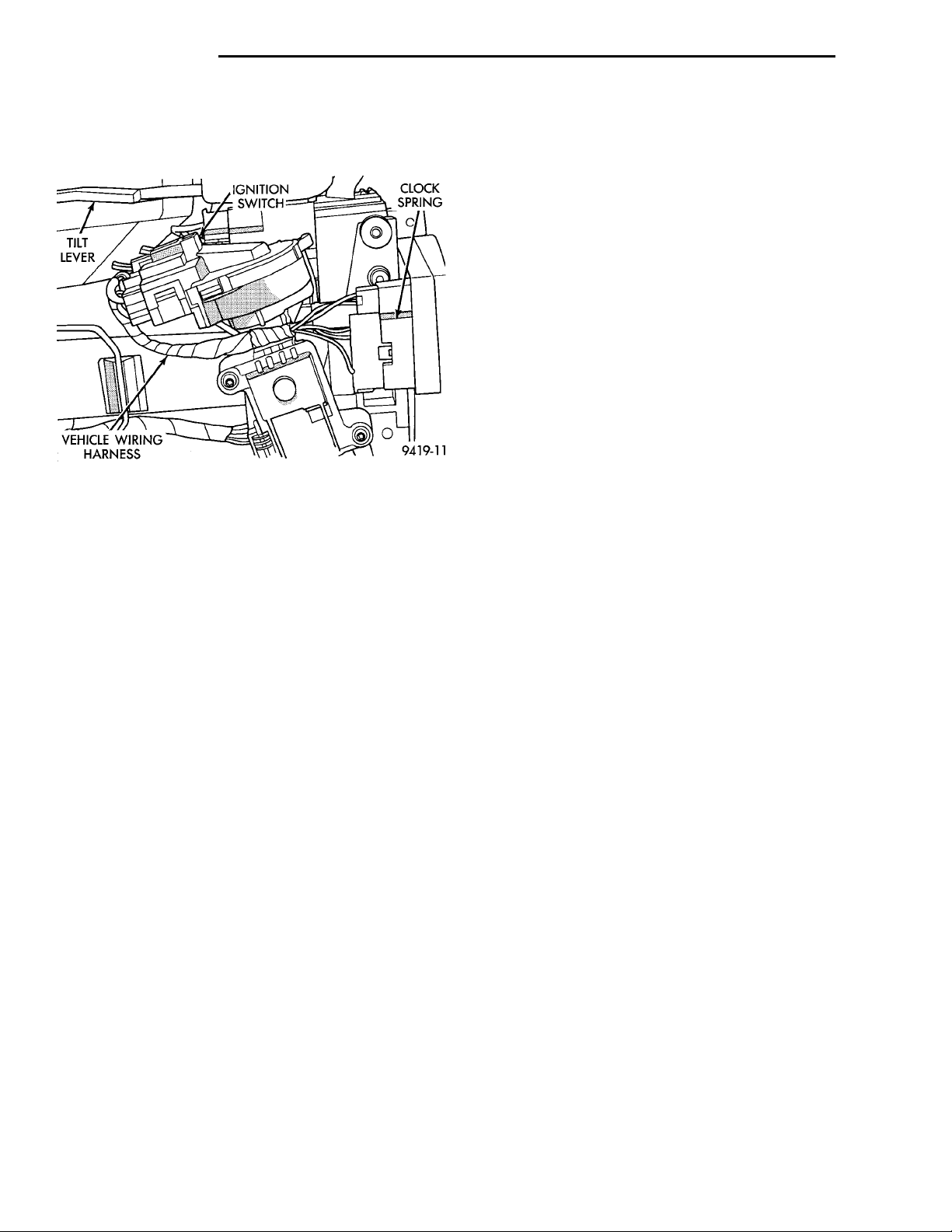
TILT LEVER
IGNITION SWITCH CLOCKSPRINGVEHICLE WIRINGHARNESS
19 - 42 STEERING PL
REMOVAL AND INSTALLATION (Continued)
(22) Remove the vehicle wiring harness connectors from the ignition switch and clock spring (Fig.
19).
Fig. 19 Steering Column Wiring Connections
(23) Remove steering column assembly from vehicle through the drivers door of the passenger compartment. Use care to avoid damaging the paint or
interior trim.
INSTALL
(1) Install steering column into steering column
access opening in lower instrument panel.
(2) Install the vehicle wiring harness connectors,
into the ignition switch and clock spring assembly
(Fig. 19).
(3) Install vehicle wiring harness connectors into
multi-function switch and turn signal switch (Fig. 18)
on steering column assembly. Install routing clip
(Fig. 18) holding wiring harness to jacket of steering
column.
(4) Install the studs in the steering column support bracket, into the slots in the plastic capsules of
the upper mounting bracket of the steering column
(Fig. 17). Partially install the 2 upper steering column assembly mounting bracket to support bracket
attaching nuts (Fig. 17). Do not tighten the 2
mounting nuts at this time.
(5) Align the bolt holes in the steering column
lower mounting bracket with the threaded holes in
the boby mounting bracket for the steeing column.
Install and loosely tighten the steering column lower
mounting bracket bolts.
(6) Install the upper and lower steering column
shrouds onto the lock housing of the steering column
assembly. Install and securely tighten the 3 upper to
lower steering column shroud to lock housing attaching screws (Fig. 15).
(7) Be sure both breakaway capsules are still fully
seated in the slots of the upper steering column
mounting bracket. Equally tighten both steering column mounting nuts, until upper steering column
mounting bracket is seated against support bracket.
Then tighten the 2 steering column upper mounting
bracket nuts to a torque of 17 N·m (150 in. lbs.).
(8) Tighten the steering column lower mounting
bracket nuts (2) to a torque of 17 N·m (150 in. lbs.).
(9) Assemble the steering column flex coupler to
the intermediate steering coupler (Fig. 16). Install
the steering coupler pinch bolt. Torque the pinch bolt
nut to 28 N·m (250 in. lbs.). Be sure to install
upper to lower steering coupler pinch bolt
retaining pin (Fig. 16).
(10) Install the lower instrument panel steering
column cover liner onto lower instrument panel.
Install and securely tighten the 3 liner to instrument
panel attaching screws (Fig. 7).
(11) Install lower instrument panel steering column cover (Fig. 6) on lower instrument panel. Install
and securely tighten the 4 screws (Fig. 6) attaching
steering column cover, to lower instrument panel.
CAUTION: Clock spring centering procedure MUST
be performed prior to installing steering wheel
assembly. If clock spring is not centered it may be
overextended, causing clock spring assembly to
become inoperative.
(12) Center the clock spring using the following
procedure.
• Depress the 2 plastic locking pins to disengage
clockspring locking mechanism.
• Keeping locking mechanism disengaged, rotate
the clockspring rotor in the CLOCKWISE DIRECTION to the end of the travel. Do not apply excessive
torque.
• From the end of travel, rotate the rotor 2 full
turns and an additional half turn in the counterclockwise direction. (The horn wire should end up at
the top and the squib wire at the bottom.) Engage
the clockspring locking mechanism.
CAUTION: Do not install steering wheel onto shaft
of steering column assembly by driving it onto the
shaft. Pull steering wheel down onto steering column shaft using ONLY the steering wheel retaining
nut.
Page 43
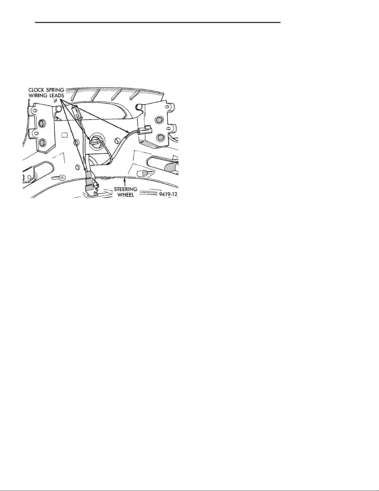
CLOCK SPRING WIR-ING LEADS STEERINGWHEEL
PL STEERING 19 - 43
REMOVAL AND INSTALLATION (Continued)
(13) Feed clock spring wiring leads through hole in
steering wheel (Fig. 20). Position steering wheel on
shaft of steering column assembly, making sure to fit
flats on hub of steering wheel with formations on
inside of clockspring.
Fig. 20 Steering Wheel Installation
(14) Install steering wheel to steering column
shaft retaining nut and tighten until steering wheel
is fully installed on shaft. The tighten steering wheel
retaining nut to a torque of 61 N·m (45 ft. lbs.).
(15) Connect the clockspring electrical leads to
components such as horn switches and speed control
switches located in the steering wheel (Fig. 11).
(16) Install air bag electrical lead from clock
spring, into connector on back of air bag module (Fig.
10). Be sure electrical connector from clock-
spring is securely latched into air bag module
connector.
CAUTION: The fasteners, screws, and bolts, originally used for the air bag components are specifically designed for the air bag system. They must
never be replaced with any substitutes. Anytime a
new fastener is needed, replace only with correct
fasteners provided in service packages or fasteners
listed in the parts book.
(17) Install air bag module into center of steering
wheel. Align air bag module mounting holes with bolt
holes in steering wheel. Install only the 2 original
or correct replacement air bag module attaching
bolts (Fig. 9). Torque the 2 air bag module attaching
bolts to 10 N·m (90 in. lbs.).
(18) Install key lock cylinder into lock housing.
Key lock cylinder is installed by positioning key cyl-
inder in the run position so retaining tab can be
depressed and the pushing key cylinder into lock hosing until retaining tab locks into key lock cylinder.
(19) Reconnect ground cable to Negative post of
the battery. When reconnecting battery on a
vehicle that has had the air bag module
removed, the following procedure should be
used.
• Remove forward console or cover as necessary.
• Connect DRB II to ASDM diagnostic 6-way con-
nector, located at right side of the ASDM module.
• Turn ignition key to ON position. Exit vehicle
with the DRB II. Install the latest version of the
proper diagnostic cartridge into the DRB II.
• Ensuring that their are no occupants in the
vehicle, connect negative cable to negative post of the
battery.
• Using the DRB II read and record active fault
codes. Also read and record any stored fault codes.
Refer to the Passive Restraint Diagnostic Test Manual if any faults are found.
• Erase stored faults if there are no active fault
codes. If problems remain, fault codes will not erase.
• From the passenger side of the vehicle, turn
ignition key to OFF and then ON observing instrument cluster air bag lamp. It should go on for six to
eight seconds, then go out. This will indicate that the
air bag system is functioning normally.
(20) If air bag warning lamp fails to light,
blinks on and off or goes on and stays on, there
is an air bag system malfunction. Refer to the
Passive Restraint Diagnostic Test Manual to diagnose the system malfunction.
(21) Test the operation of the horn, lights and any
other functions that are steering column operated. If
applicable reset the radio and the clock.
(22) Road test vehicle to ensure proper operation
of the steering system and the speed control system.
SPECIFICATIONS
STEERING COLUMN FASTENER TORQUE SPECIFICATIONS
DESCRIPTION TORQUE
Steering Wheel
Retaining Nut ...............61N·m(45ft.lbs.)
Steering Column Assembly
Upper Mounting Bracket
Attaching Nuts ...........17N·m(150 in. lbs.)
Page 44

 Loading...