

Page 1

PL FUEL SYSTEM 14 - 1
FUEL SYSTEM
CONTENTS
page page
FUEL DELIVERY SYSTEM ................. 3
FUEL INJECTION SYSTEM ................ 21
GENERAL INFORMATION
INDEX
page page
GENERAL INFORMATION
FUEL REQUIREMENTS ................... 1
GENERAL INFORMATION
INTRODUCTION
Throughout this group, references may be made to
a particular vehicle by letter or number designation.
A chart showing the breakdown of these designations
is included in the Introduction Section at the front of
this service manual.
The Evaporation Control System, is also considered
part of the fuel system. The system reduces the emission of fuel vapor into the atmosphere.
The description and function of the Evaporation
Control System is found in Group 25 of this manual.
FUEL REQUIREMENTS
Your vehicle was designed to meet all emission regulations and provide excellent fuel economy when
using high quality unleaded gasoline.
Use unleaded gasolines having a minimum posted
octane of 87.
If your vehicle develops occasional light spark
knock (ping) at low engine speeds this is not harmful. However; continued heavy knock at high speeds
can cause damage and should be reported to your
dealer immediately. Engine damage as a result of
heavy knock operation may not be covered by the
new vehicle warranty.
In addition to using unleaded gasoline with the
proper octane rating, those that contain detergents,
corrosion and stability additives are recommended.
Using gasolines that have these additives will help
improve fuel economy, reduce emissions, and maintain vehicle performance.
GENERAL INFORMATION .................. 1
GASOLINE/OXYGENATE BLENDS ........... 1
INTRODUCTION ........................ 1
Poor quality gasoline can cause problems such as
hard starting, stalling, and stumble. If you experience these problems, try another brand of gasoline
before considering service for the vehicle.
GASOLINE/OXYGENATE BLENDS
Some fuel suppliers blend unleaded gasoline with
materials that contain oxygen such as alcohol, MTBE
(Methyl Tertiary Butyl Ether) and ETBE (Ethyl Tertiary Butyl Ether). Oxygenates are required in some
areas of the country during winter months to reduce
carbon monoxide emissions. The type and amount of
oxygenate used in the blend is important.
The following are generally used in gasoline
blends:
Ethanol - (Ethyl or Grain Alcohol) properly
blended, is used as a mixture of 10 percent ethanol
and 90 percent gasoline. Gasoline blended with ethanol may be used in your vehicle.
MTBE/ETBE - Gasoline and MTBE (Methyl Tertiary Butyl Ether) blends are a mixture of unleaded
gasoline and up to 15 percent MTBE. Gasoline and
ETBE (Ethyl Tertiary Butyl Ether) are blends of gasoline and up to 17 percent ETBE. Gasoline blended
with MTBE or ETBE may be used in your vehicle.
Methanol - Methanol (Methyl or Wood Alcohol) is
used in a variety of concentrations blended with
unleaded gasoline. You may encounter fuels containing 3 percent or more methanol along with other
alcohols called cosolvents.
DO NOT USE GASOLINES CONTAINING
METHANOL.
Page 2

14 - 2 FUEL SYSTEM PL
GENERAL INFORMATION (Continued)
Use of methanol/gasoline blends may result in
starting and driveability problems and damage critical fuel system components.
Problems that are the result of using methanol/
gasoline blends are not the responsibility of Chrysler
Corporation and may not be covered by the vehicle
warranty.
Reformulated Gasoline
Many areas of the country are requiring the use of
cleaner-burning fuel referred to as Reformulated
Gasoline . Reformulated gasolines are specially
blended to reduce vehicle emissions and improve air
quality.
Chrysler Corporation strongly supports the use of
reformulated gasolines whenever available. Although
your vehicle was designed to provide optimum performance and lowest emissions operating on high quality unleaded gasoline, it will perform equally well
and produce even lower emissions when operating on
reformulated gasoline.
Materials Added to Fuel
Indiscriminate use of fuel system cleaning agents
should be avoided. Many of these materials intended
for gum and varnish removal may contain active solvents of similar ingredients that can be harmful to
fuel system gasket and diaphragm materials.
Page 3
FUEL FILTER/PRESSUREREGULATOR FUEL LEVEL SENSORFUEL RESERVOIR INLET STRAINER FLOAT
PL FUEL SYSTEM 14 - 3
FUEL DELIVERY SYSTEM
INDEX
page page
DESCRIPTION AND OPERATION
ELECTRIC FUEL PUMP ................... 4
FUEL DELIVERY SYSTEM ................. 3
FUEL FILTER/FUEL PRESSURE REGULATOR . . 4
FUEL GAUGE SENDING UNIT .............. 4
FUEL INJECTORS ....................... 5
FUEL PUMP MODULE .................... 3
FUEL RAIL ............................. 4
FUEL TANK ............................ 4
PRESSURE-VACUUM FILLER CAP .......... 5
QUICK-CONNECT FITTINGS ............... 5
ROLLOVER VALVES ..................... 6
DIAGNOSIS AND TESTING
FUEL INJECTORS ....................... 8
FUEL LEVEL SENSOR .................... 8
FUEL PUMP PRESSURE TEST ............. 6
SERVICE PROCEDURES
DRAINING FUEL TANK .................. 10
FUEL SYSTEM PRESSURE RELEASE
PROCEDURE ........................ 10
DESCRIPTION AND OPERATION
FUEL DELIVERY SYSTEM
The fuel delivery system consists of: the electric
fuel pump, fuel filter/fuel pressure regulator, fuel
tubes/lines/hoses, fuel rail, fuel injectors, fuel tank,
accelerator pedal and throttle cable.
A fuel return system is used on all models (all
engines). Fuel is returned through the fuel pump
module and back into the fuel tank through the fuel
filter/fuel pressure regulator. A separate fuel return
line from the engine to the tank is no longer used
with any engine.
The fuel tank assembly consists of: the fuel tank,
filler tube, fuel gauge sending unit/electric fuel pump
module, a pressure relief/rollover valve and a pressure-vacuum filler cap.
Also to be considered part of the fuel system is the
evaporation control system. This is designed to
reduce the emission of fuel vapors into the atmosphere. The description and function of the Evaporative Control System is found in Group 25, Emission
Control Systems.
HOSES AND CLAMPS ................... 10
QUICK-CONNECT FITTINGS .............. 11
REMOVAL AND INSTALLATION
ACCELERATOR PEDAL .................. 18
AUTOMATIC SHUTDOWN RELAY .......... 12
FUEL FILLER NECK ..................... 17
FUEL FILLER TUBE ROLLOVER VALVE ...... 17
FUEL FILTER / PRESSURE REGULATOR .... 13
FUEL INJECTORS ...................... 15
FUEL LEVEL SENSOR ................... 14
FUEL PUMP INLET STRAINER ............ 14
FUEL PUMP MODULE ................... 12
FUEL PUMP RELAY ..................... 12
FUEL TANK ........................... 16
THROTTLE CABLE—AUTOMATIC
TRANSMISSION ...................... 19
THROTTLE CABLE—MANUAL
TRANSMISSION ...................... 18
SPECIFICATIONS
TORQUE SPECIFICATION ................ 20
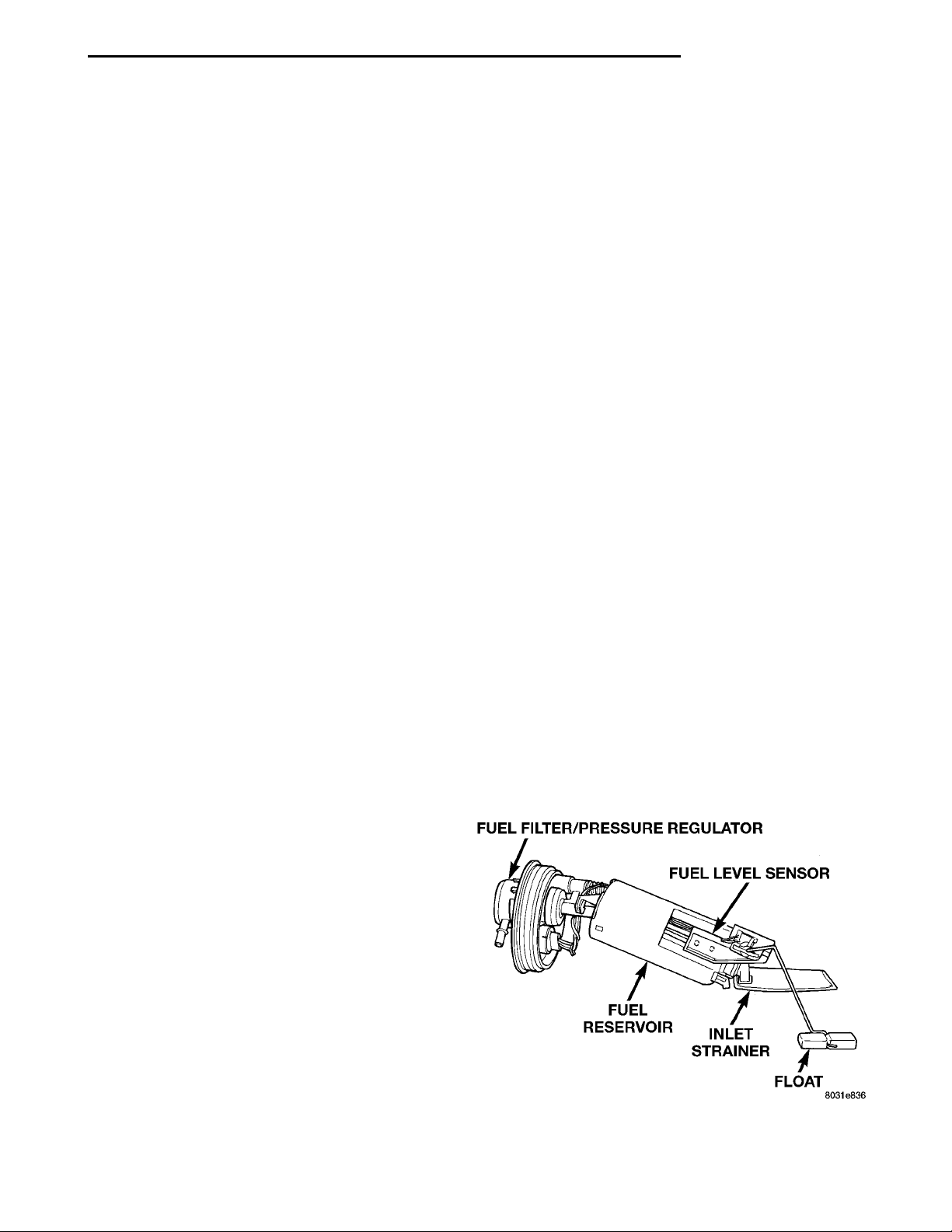
• Electric fuel pump
• Fuel pump reservoir
• Inlet strainer
• Fuel filter/pressure regulator
• Fuel gauge sending unit
• Fuel supply line connection
The inlet strainer, fuel pressure regulator and fuel
level sensor are the only serviceable items. If the fuel
pump requires service, replace the fuel pump module.
FUEL PUMP MODULE
The fuel pump module is installed in the top of the
fuel tank (Fig. 1). The fuel pump module contains the
following:
Fig. 1 Fuel Pump Module
Page 4
INTERNAL FUEL FILTER FUEL FLOW TO FUEL INJEC-TORSFUEL FILTER/FUEL PRES-SURE REGULATORO-RINGSEXCESS FUEL BACK TOTANKFUEL INLETCALIBRATED SPRINGSRUBBER GROM-MET AT PUMPMODULELOCKINGTAB
14 - 4 FUEL SYSTEM PL
DESCRIPTION AND OPERATION (Continued)
ELECTRIC FUEL PUMP
The electric fuel pump is located in and is part of
the fuel pump module. It is a positive displacement,
gerotor type, immersible pump with a permanent
magnet electric motor. The fuel pump module is suspended in fuel in the fuel tank. The pump draws fuel
through a strainer and pushes it through the motor
to the outlet. The pump contains a check valves. The
valve, in the pump outlet, maintains pump pressure
during engine off conditions. The fuel pump relay
provides voltage to the fuel pump.
The fuel pump has a maximum deadheaded pressure output of approximately 880 kPa (130 psi). The
regulator adjusts fuel system pressure to approximately 338 kPa (49 psi).
FUEL GAUGE SENDING UNIT
The fuel gauge sending unit (fuel level sensor) is
attached to the side of the fuel pump module. The
sending unit consists of a float, an arm, and a variable resistor (track). The resistor track is used to
send electrical signals to the Powertrain Control
Module (PCM) for fuel gauge operation and for OBD
II emission requirements.
For fuel gauge operation: As fuel level
increases, the float and arm move up. This decreases
the sending unit resistance, causing the fuel gauge to
read full. As fuel level decreases, the float and arm
move down. This increases the sending unit resistance causing the fuel gauge to read empty.
After this fuel level signal is sent to the PCM, the
PCM will transmit the data across the CCD bus circuits to the instrument panel. Here it is translated
into the appropriate fuel gauge level reading.
For OBD II emission requirements: The voltage
signal is sent from the resistor track to the PCM to
indicate fuel level. The purpose of this feature is to
prevent a false setting of misfire and fuel system
monitor trouble codes. This is if the fuel level in the
tank is less than approximately 15 percent of its
rated capacity.
FUEL FILTER/FUEL PRESSURE REGULATOR
A combination fuel filter and fuel pressure regulator is used on all gas powered engines. It is located
on the top of the fuel pump module. A separate frame
mounted fuel filter is not used.
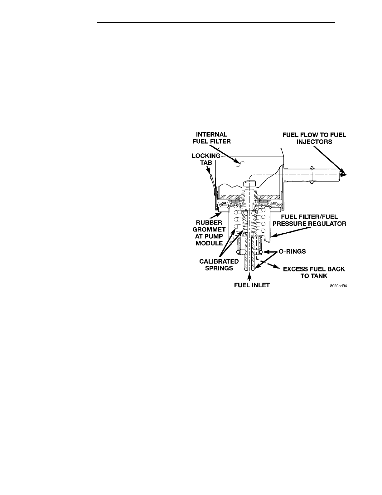
Fuel Pressure Regulator Operation: The pressure regulator is a mechanical device that is calibrated to maintain fuel system operating pressure of
approximately 338 kPa (49 psi) at the fuel injectors.
It contains a diaphragm, calibrated springs and a
fuel return valve. The internal fuel filter (Fig. 2) is
also part of the assembly.
Fuel is supplied to the filter/regulator by the electric fuel pump through an opening tube at the bottom of filter/regulator.
The fuel pump module contains a check valve to
maintain some fuel pressure when the engine is not
operating. This will help to start the engine.
If fuel pressure at the pressure regulator exceeds
approximately 49 psi, an internal diaphragm closes
and excess fuel pressure is routed back into the tank
through the pressure regulator. A separate fuel
return line is not used with any gas powered engine.
Fig. 2 Side View—Filter/Regulator
FUEL TANK
All models pass a full 360 degree rollover test
without fuel leakage. To accomplish this, fuel and
vapor flow controls are required for all fuel tank connections.
All models have a pressure relief/rollover valve
mounted on the top of the fuel pump module.
An evaporative control system is used to reduce
emissions of fuel vapors into atmosphere by evaporation and to reduce unburned hydrocarbons emitted
by vehicle engine. When fuel evaporates from fuel
tank, vapors pass through vent hoses or tubes to a
charcoal canister. The vapors are temporarily held in
the canister. When the engine is running, the vapors
are drawn into intake manifold. Refer to Group 25,
Emission Control System for additional information.
FUEL RAIL
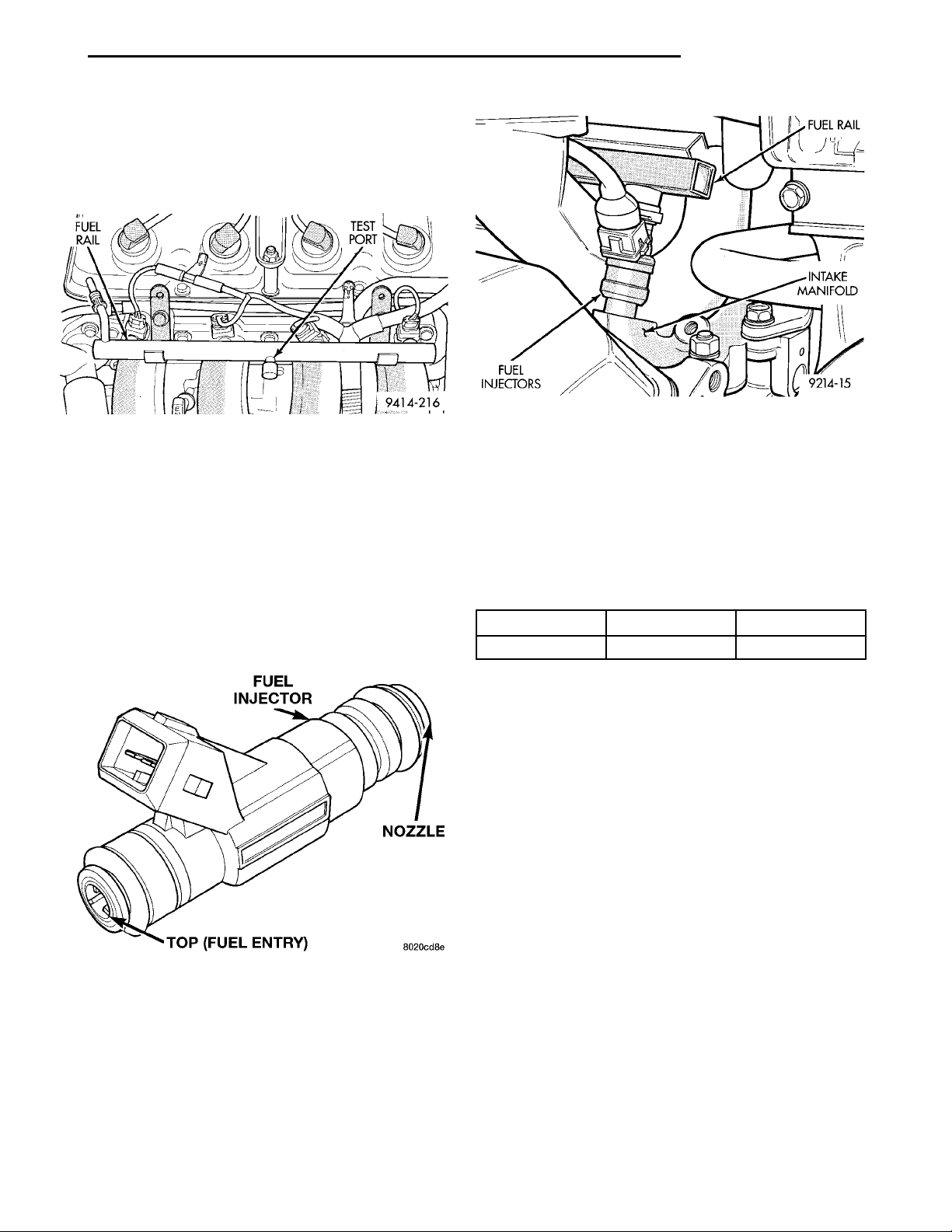
The fuel rail supplies the necessary fuel to each
individual fuel injector and is mounted to the intake
manifold (Fig. 3). The fuel pressure regulator is no
Page 5
FUEL RAIL TEST PORT
FUEL INJECTOR NOZZLETOP (FUEL ENTRY)
FUEL INJEC-TORS
FUEL RAIL
INTAKE MANI-
FOLD
PL FUEL SYSTEM 14 - 5
DESCRIPTION AND OPERATION (Continued)
longer mounted to the fuel rail on any engine. It is
now located on the fuel tank mounted fuel pump
module. Refer to Fuel Filter/Fuel Pressure Regulator
in the Fuel Delivery System section of this group for
information. The fuel rail is not repairable.
Fig. 5 Fuel Injector Location—Typical
Fig. 3 Fuel Rail—Typical
FUEL INJECTORS
The fuel injectors are 12 ohm electrical solenoids
(Fig. 4). The injector contains a pintle that closes off
an orifice at the nozzle end. When electric current is
supplied to the injector, the armature and needle
move a short distance against a spring, allowing fuel
to flow out the orifice. Because the fuel is under high
pressure, a fine spray is developed in the shape of a
hollow cone. The spraying action atomizes the fuel,
adding it to the air entering the combustion chamber.
The injectors are positioned in the intake manifold.
release for all gas caps is between 0.97 and 2.0 kPa
(0.14 and 0.29 psi). The cap must be replaced by a
similar unit if replacement is necessary.
WARNING: REMOVE FILLER CAP TO RELIEVE
TANK PRESSURE BEFORE REMOVING OR REPAIRING FUEL SYSTEM COMPONENTS.
Fuel Tank Capacity
Vehicle Liters U.S.Gallons
PL 47 12.5
Fig. 4 Fuel Injector
The injectors are positioned in the intake manifold
with the nozzle ends directly above the intake valve
port (Fig. 5).
PRESSURE-VACUUM FILLER CAP
The loss of any fuel or vapor out of the filler neck
is prevented by the use of a safety filler cap. The cap
will release pressure only under significant pressure
of 10.9 to 13.45 kPa (1.58 to 1.95 psi). The vacuum
NOTE: Nominal refill capacities are shown. A variation may be observed from vehicle due to manufacturing tolerance and refill procedure.
QUICK-CONNECT FITTINGS
Different types of quick-connect fittings are used to
attach various fuel system components. These are: a
single-tab type, a two-tab type or a plastic retainer
ring type. Some are equipped with safety latch clips.
Refer to the Removal/Installation section for more
information.
CAUTION: The interior components (o-rings, spacers) of quick-connect fitting are not serviced separately. Do not attempt to repair damaged fittings or
fuel lines/tubes. If repair is necessary, replace the
complete fuel tube assembly.
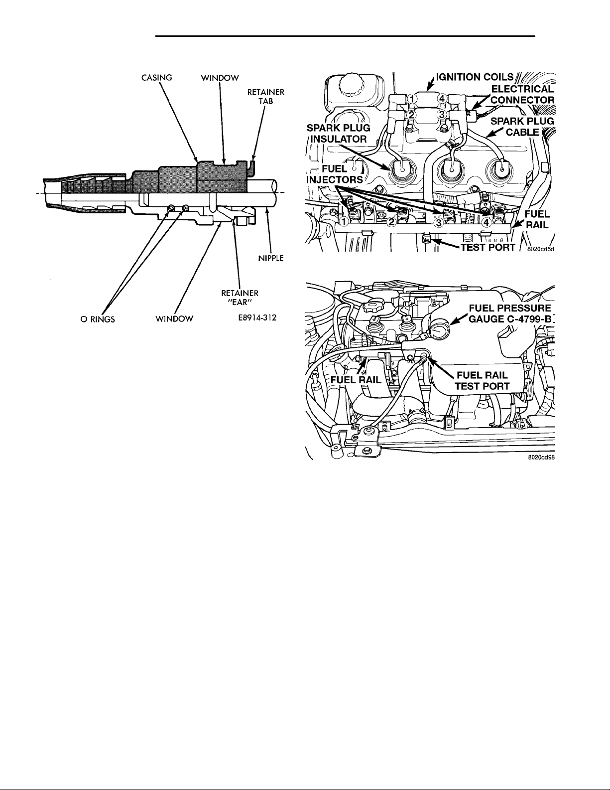
Fuel tubes connect fuel system components with
plastic quick-connect fuel fittings. The fitting contains non-serviceable O-ring seals (Fig. 6).
CAUTION: Quick-connect fittings are not serviced
separately. Do not attempt to repair damaged quickconnect fittings or fuel tubes. Replace the complete
fuel tube/quick-connect fitting assembly.
Page 6
CASING WINDOW RETAINER TABNIPPLEO RINGSWINDOWRETAINER “EAR”
FUEL RAIL
IGNITION COILSELECTRICAL CON-NECTOR
TEST PORTFUEL INJEC-TORSSPARK PLUGINSULATOR
FUEL PRESSURE GAUGEC-4799-B
FUEL RAIL TEST PORT
SPARK PLUG
FUEL RAIL
CABLE
14 - 6 FUEL SYSTEM PL
DESCRIPTION AND OPERATION (Continued)
Fig. 7 Fuel Pressure Test Port—Typical
Fig. 6 Plastic Quick-Connect Fittings
The quick-connect fitting consists of the O-rings,
retainer and casing (Fig. 6). When the fuel tube
enters the fitting, the retainer locks the shoulder of
the nipple in place and the O-rings seal the tube.
ROLLOVER VALVES
All PL vehicles have two rollover valves. One in
the fuel filler tube and the other on the top of the
fuel tank. The valves prevent fuel flow through the
fuel tank vent valve hoses should the vehicle rollover.
DIAGNOSIS AND TESTING
FUEL PUMP PRESSURE TEST
The fuel system operates at approximately 338 kPa
(49 psi). Check fuel system pressure at the test port
on the fuel rail (Fig. 7).
(1) Remove cap from fuel pressure test port on fuel
rail.
(2) Connect Fuel Pressure Gauge C-4799B to test
port (Fig. 8).
CAUTION: When using the ASD Fuel System Test,
the ASD relay and fuel pump relay remain energized
for 7 minutes or until the test is stopped, or until
the ignition switch is turned to the Off position.
Fig. 8 Checking Fuel Pressure at Intake Manifold—
Typical
• If the gauge reading equals 338 kPa (49 PSI)
further testing is not required. If pressure is not correct, record the pressure.
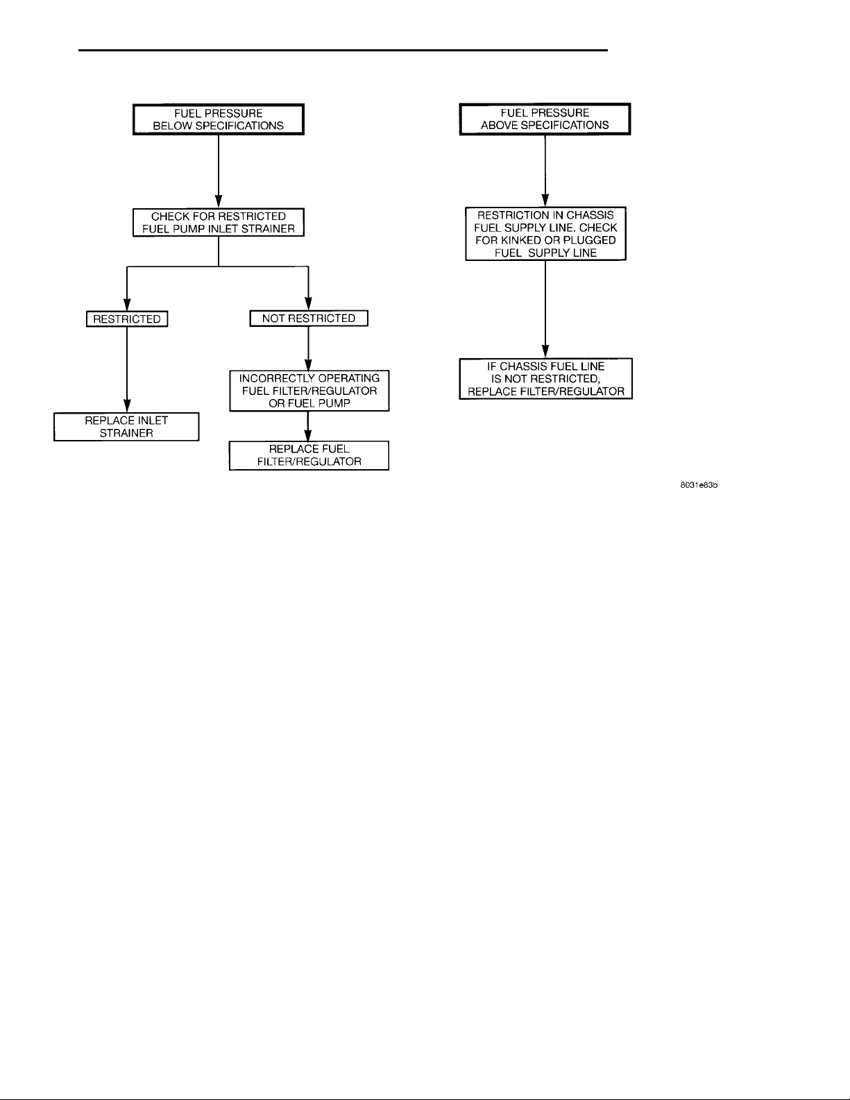
• If fuel pressure is below specifications, refer to
the Fuel Pressure Diagnosis Chart (Fig. 9).
• If fuel pressure is above specifications (54 psi or
higher) check for a kinked or restricted fuel supply
line. If the supply line is not kinked or restricted,
replace the Fuel Filter/Pressure Regulator.
(3) Place the ignition key in the ON position.
Using the DRB scan tool, access ASD Fuel System
Test. The ASD Fuel System Test will activate the fuel
pump and pressurize the system.
Page 7
IF CHASSIS FUEL LINE ISNOT RESTRICTED.REPLACE FILTER/REGULA-TOR
RESTRICTEDREPLACE INLET STRAINER NOT RESTRICTEDINCORRECTLY OPERATING FUELFILTER/REGULATOR OR FUEL PUMPREPLACE FUEL FILTER/REG-ULATOR
FUEL PRESSURE BELOW SPECIFICA-
CHECK FOR RESTRICTED FUEL PUMP
TIONS
INLET STRAINER
FUEL PRESSURE ABOVE SPECIFICATIONSRESTRICTION IN CHASSIS FUEL SUP-
PLY LINE. CHECK FOR KINKED OR
PLUGGED FUEL SUPPLY LINE
PL FUEL SYSTEM 14 - 7
DIAGNOSIS AND TESTING (Continued)
Fig. 9 Fuel Pressure Diagnosis Chart
Page 8
14 - 8 FUEL SYSTEM PL
DIAGNOSIS AND TESTING (Continued)
FUEL LEVEL SENSOR
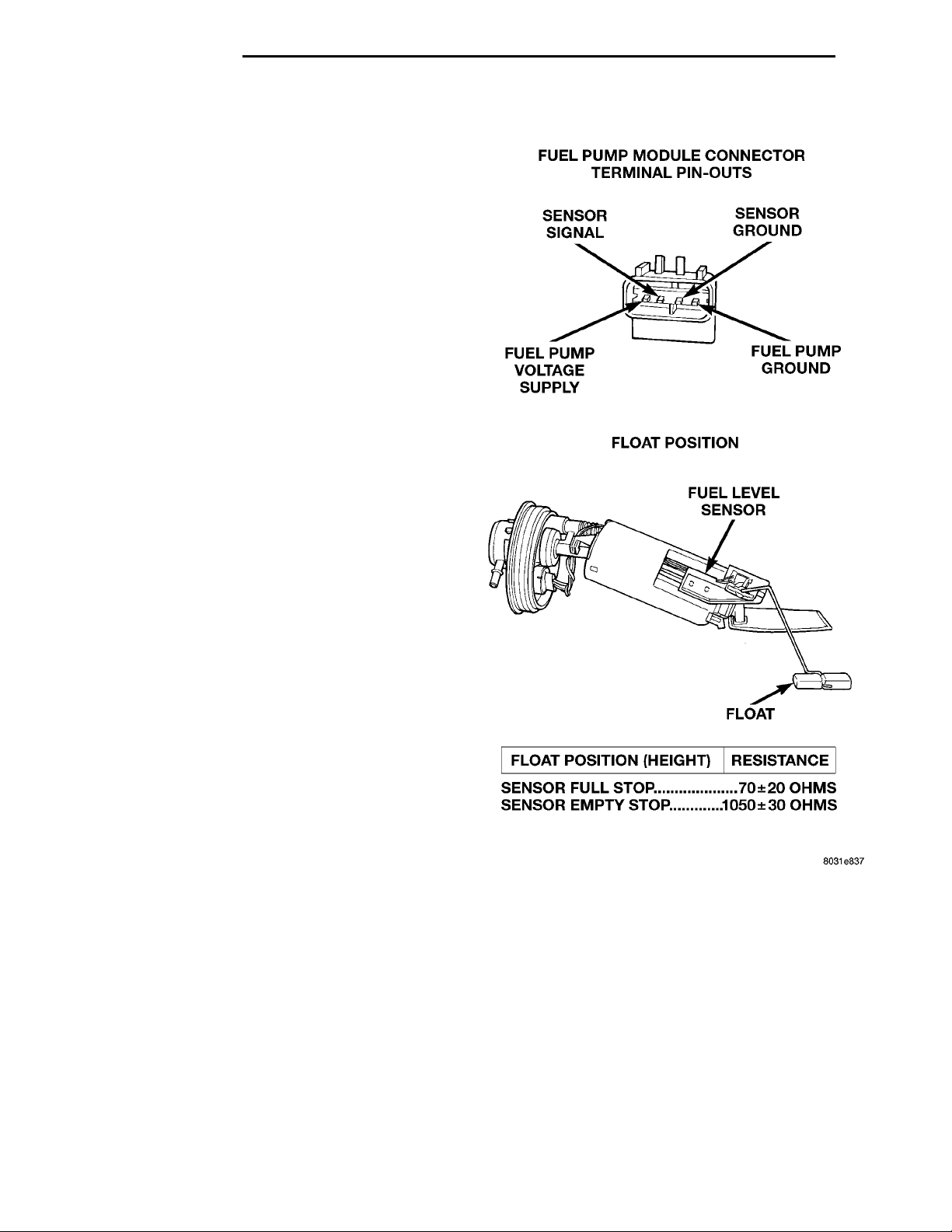
This procedure tests the resistance of the level sensor itself. It does not test the level sensor circuit.
Refer to Group 8W - Wiring Diagrams for circuit
identification.
The level sensor is a variable resistor. Its resistance changes with the amount of fuel in the tank.
The float arm attached to the sensor moves as the
fuel level changes. To test the level sensor, connect
an ohmmeter across the sensor signal and sensor
ground terminals of the fuel pump module connector
(Fig. 10). Move the float lever to the positions shown
in the resistance chart (Fig. 10). Record the resistance at each point. Replace the level sensor if the
resistance is not within specifications.
FUEL INJECTORS
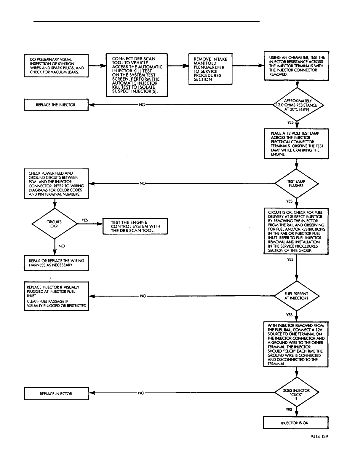
For fuel injector diagnosis, refer to the Fuel Injector Diagnosis charts. For poor fuel economy diagnosis
or engine miss, also refer to Transmission Driveplate
in this section
Fig. 10 Level Sensor Diagnosis
Page 9
DO PRELIMINARY VISUALINSPECTION OF IGNITIONWIRES AND SPARK PLUGS,AND CHECK FOR VACUUMLEAKS. CONNECT DRB SCAN TOOL TOVEHICLE. ACCESS THE AUTO-MATIC INJECTOR KILL TEST ONTHE SYSTEM TEST SCREEN.PERFORM THE AUTOMATICINJECTOR KILL TEST TO ISO-LATE SUSPECT INJECTOR(S). REMOVE INTAKEMANIFOLD PLENUM.REFER TO SERVICEPROCEDURES SEC-TION. USING AN OHMMETER, TEST THEINJECTOR RESISTANCE ACROSSTHE INJECTOR TERMINALS WITHTHE INJECTOR CONNECTORREMOVED.
REPLACE THE INJECTOR. YESPLACE A 12 VOLT TEST LAMPACROSS THE INJECTOR ELECTRI-CAL CONNECTOR TERMINALS.OBSERVE THE TEST LAMP WHILECRANKING THE ENGINE.TEST LAMP FLASHESNOCHECK POWER FEED ANDGROUND CIRCUITSBETWEEN PCM AND THEINJECTOR CONNECTOR.REFER TO WIRING DIA-GRAMS FOR COLOR CODESAND PIN TERMINAL NUM-BERS.CIRCUITS OK?YESTEST THE ENGINE CON-TROL SYSTEM WITH THEDRB SCAN TOOL.NOREPAIR OR REPLACE THEWIRING HARNESS AS NEC-ESSARY.YESCIRCUIT IS OK. CHECK FORFUEL DELIVERY AT SUS-PECT INJECTOR BY REMOV-ING THE INJECTOR FROMTHE RAIL AND OBSERVINGFOR FUEL AND/ORRESTRICTIONS I THE RAILOR INJECTOR FUEL INLET.REFER TO FUEL INJECTORREMOVAL AND INSTALLA-TION IN THE SERVICE PRO-CEDURES SECTION OF THISGROUP.YESNOREPLACE INJECTOR IFVISUALLY PLUGGED ATINJECTOR FUEL INLET.CLEAN FUEL PASSAGE IFVISUALLY PLUGGED ORRESTRICTED.FUEL PRESENT AT INJEC-TOR?YESWITH INJECTOR REMOVEDFROM THE FUEL RAIL, CON-NECT A 12V SOURCE TOONE TERMINAL ON THEINJECTOR CONNECTORAND A GROUND WIRE TOTHE OTHER TERMINAL. THEINJECTOR SHOULD “CLICK”EACH TIME THE GROUNDWIRE IS CONNECTED ANDDISCONNECTED TO THETERMINAL.DOES INJECTOR “CLICK”?NOREPLACE INJECTOR.YESINJECTOR IS OK.
PL FUEL SYSTEM 14 - 9
NO
APPROXIMATELY 12.0
OHMS RESISTANCE
AT 20°C (68°F)
DIAGNOSIS AND TESTING (Continued)
.
FUEL INJECTOR DIAGNOSIS
Page 10
14 - 10 FUEL SYSTEM PL
SERVICE PROCEDURES
FUEL SYSTEM PRESSURE RELEASE PROCEDURE
WARNING: RELEASE FUEL SYSTEM PRESSURE
BEFORE SERVICING FUEL SYSTEM COMPONENTS.
SERVICE VEHICLES IN WELL VENTILATED AREAS
AND AVOID IGNITION SOURCES. NEVER SMOKE
WHILE SERVICING THE VEHICLE.
(1) Disconnect negative cable from battery.
(2) Remove fuel filler cap.
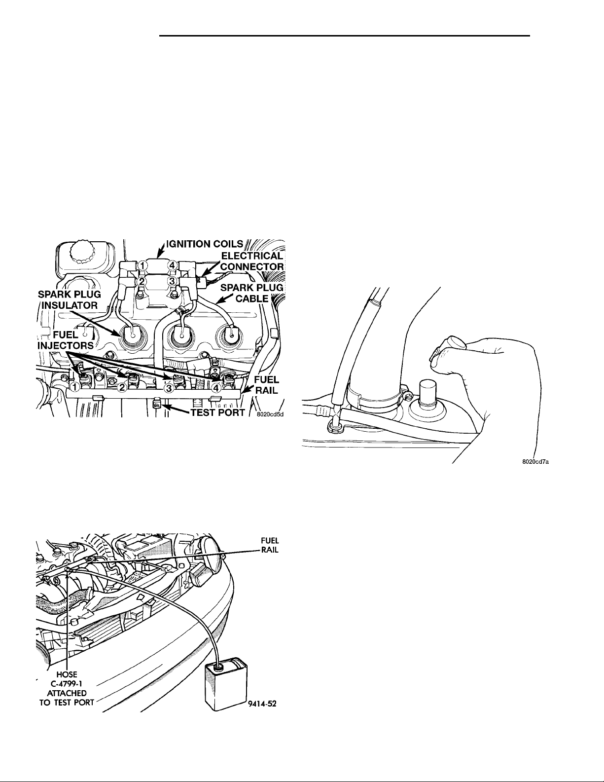
(3) Remove the protective cap from the fuel pressure test port on the fuel rail (Fig. 11).
IGNITION COILSELECTRICAL CON-NECTOR
TEST PORTFUEL INJEC-TORSSPARK PLUGINSULATOR
SPARK PLUG
FUEL RAIL
CABLE
FUEL RAILHOSEC-4799-1ATTACHEDTO TESTPORT
DRAINING FUEL TANK
WARNING: RELEASE FUEL SYSTEM PRESSURE
BEFORE SERVICING FUEL SYSTEM COMPONENTS.
SERVICE VEHICLES IN WELL VENTILATED AREAS
AND AVOID IGNITION SOURCES. NEVER SMOKE
WHILE SERVICING THE VEHICLE.
(1) Remove fuel filler cap.
(2) Perform the Fuel System Pressure Release pro-
cedure.
(3) Disconnect negative cable from battery.
(4) Raise vehicle on hoist.
(5) Remove quick connect cap from drain port. The
drain port is located on rear top of fuel tank. Push a
siphon hose into the drain port (Fig. 13).
(6) Drain fuel tank into holding tank or a properly
labeled Gasoline safety container.
Fig. 11 Fuel Pressure Test Port—Typical
(4) Place the open end of fuel pressure release
hose, tool number C-4799-1, into an approved gasoline container. Connect the other end of hose
C-4799-1 to the fuel pressure test port (Fig. 12). Fuel
pressure will bleed off through the hose into the gasoline container. Fuel gauge C-4799-A contains hose
C-4799-1.
Fig. 12 Releasing Fuel Pressure
Fig. 13 Drain Port Location
HOSES AND CLAMPS
Inspect all hose connections (clamps and quick connect fittings) for completeness and leaks. Replace
cracked, scuffed, or swelled hoses. Replace hoses that
rub against other vehicle components or show sign of
wear.
Fuel injected vehicles use specially constructed
hoses. When replacing hoses, only use hoses marked
EFM/EFI.
When installing hoses, ensure that they are routed
away from contact with other vehicle components
that could rub against them and cause failure. Avoid
contact with clamps or other components that cause
abrasions or scuffing. Ensure that rubber hoses are
properly routed and avoid heat sources.
The hose clamps have rolled edges to prevent the
clamp from cutting into the hose. Only use clamps
that are original equipment or equivalent. Other
types of clamps may cut into the hoses and cause
high pressure fuel leaks. Tighten hose clamps to 1
N·m (10 in. lbs.) torque.
Page 11
PL FUEL SYSTEM 14 - 11
SERVICE PROCEDURES (Continued)
QUICK-CONNECT FITTINGS
REMOVAL
When disconnecting a quick-connect fitting, the
retainer will remain on the fuel tube nipple.
WARNING: RELEASE FUEL SYSTEM PRESSURE
BEFORE DISCONNECTING A QUICK-CONNECT FITTINGS. REFER TO THE FUEL PRESSURE RELEASE
PROCEDURE.
(1) Disconnect negative cable from battery.
(2) Perform Fuel Pressure Release Procedure.
Refer to the Fuel Pressure Release Procedure in this
section.
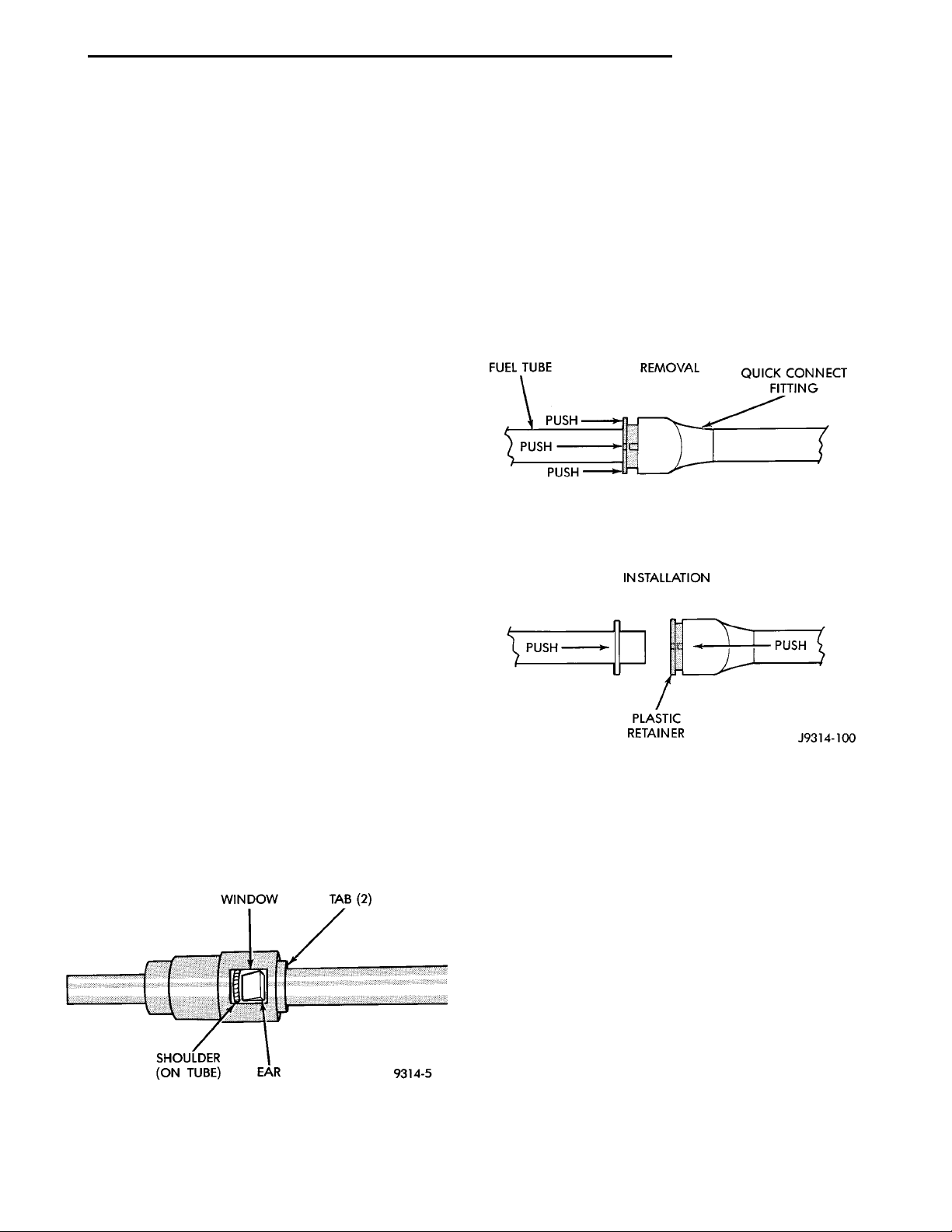
(3) Squeeze retainer tabs together and pull fuel
tube/quick-connect fitting assembly off of fuel tube
nipple. The retainer will remain on fuel tube.
INSTALLATION
CAUTION: Never install a quick-connect fitting
without the retainer being either on the fuel tube or
already in the quick-connect fitting. In either case,
ensure the retainer locks securely into the quickconnect fitting by firmly pulling on fuel tube and fitting to ensure it is secured.
CAUTION: When using the ASD Fuel System Test,
the Auto Shutdown (ASD) Relay remains energized
for either 7 minutes, until the test is stopped, or
until the ignition switch is turned to the Off position.
(5) Use the DRB scan tool ASD Fuel System Test
to pressurize the fuel system. Check for leaks.
PLASTIC RETAINER RING TYPE FITTING
This type of fitting can be identified by the use of a
full-round plastic retainer ring (Fig. 15) usually black
in color.
(1) Using a clean lint free cloth, clean the fuel tube
nipple and retainer.
(2) Prior to connecting the fitting to the fuel tube,
coat the fuel tube nipple with clean 30 weight engine
oil.
(3) Push the quick-connect fitting over the fuel
tube until the retainer seats and a click is heard.
(4) The plastic quick-connect fitting has windows
in the sides of the casing. When the fitting completely attaches to the fuel tube, the retainer locking
ears and the fuel tube shoulder are visible in the
windows. If they are not visible, the retainer was not
properly installed (Fig. 14). Do not rely upon the
audible click to confirm a secure connection.
WINDOW TAB (2)EARSHOULDER (ON TUBE)
Fig. 15 Plastic Retainer Ring Type Fitting
CAUTION: The interior components (o-rings, spacers, retainers) of this type of quick-connect fitting
are not serviced separately. Do not attempt to repair
damaged fittings or fuel lines/tubes. If repair is necessary, replace the complete fuel tube assembly.
WARNING: THE FUEL SYSTEM IS UNDER A CONSTANT PRESSURE (EVEN WITH THE ENGINE OFF).
BEFORE SERVICING ANY FUEL SYSTEM HOSES,
FITTINGS OR LINES, THE FUEL SYSTEM PRESSURE MUST BE RELEASED. REFER TO THE FUEL
SYSTEM PRESSURE RELEASE PROCEDURE IN
THIS GROUP.
Fig. 14 Plastic Quick-Connect Fitting/Fuel Tube
Connection
DISCONNECTION/CONNECTION
(1) Disconnect negative battery cable from the bat-
tery.
Page 12
BATTERY POSITIVEBATTERY GROUNDAIR CLEANERPCMPDCTCM
14 - 12 FUEL SYSTEM PL
SERVICE PROCEDURES (Continued)
(2) Perform the fuel pressure release procedure.
Refer to the Fuel Pressure Release Procedure in this
section.
(3) Clean the fitting of any foreign material before
disassembly.
(4) To release the fuel system component from the
quick-connect fitting, firmly push the fitting towards
the component being serviced while firmly pushing
the plastic retainer ring into the fitting (Fig. 15).
With the plastic ring depressed, pull the fitting from
the component. The plastic retainer ring must be
pressed squarely into the fitting body. If this
retainer is cocked during removal, it may be
difficult to disconnect fitting. Use an open-end
wrench on the shoulder of the plastic retainer
ring to aid in disconnection.
(5) After disconnection, the plastic retainer ring
will remain with the quick-connect fitting connector
body.
(6) Inspect fitting connector body, plastic retainer
ring and fuel system component for damage. Replace
as necessary.
(7) Prior to connecting the quick-connect fitting to
component being serviced, check condition of fitting
and component. Clean the parts with a lint-free
cloth. Lubricate them with clean engine oil.
(8) Insert the quick-connect fitting into the component being serviced until a click is felt.
(9) Verify a locked condition by firmly pulling on
fuel tube and fitting (15-30 lbs.).
(10) Connect negative battery cable to battery.
(11) Start engine and check for leaks.
REMOVAL AND INSTALLATION
AUTOMATIC SHUTDOWN RELAY
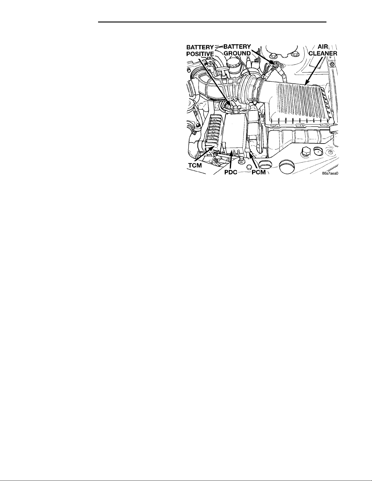
The relay is located in the Power Distribution Center (PDC) (Fig. 16). The PDC is located next to the
battery in the engine compartment. For the location
of the relay within the PDC, refer to the PDC cover
for location. Check electrical terminals for corrosion
and repair as necessary.
FUEL PUMP RELAY
The fuel pump relay is located in the PDC. The
inside top of the PDC cover has a label showing relay
and fuse location.
FUEL PUMP MODULE
REMOVAL
WARNING: RELEASE FUEL SYSTEM PRESSURE
BEFORE SERVICING FUEL SYSTEM COMPONENTS.
SERVICE VEHICLES IN WELL VENTILATED AREAS
AND AVOID IGNITION SOURCES. NEVER SMOKE
WHILE SERVICING THE VEHICLE.
the Fuel Tank section of this group.
WARNING: THE FUEL RESERVOIR OF THE FUEL
PUMP MODULE DOES NOT EMPTY OUT WHEN THE
TANK IS DRAINED. THE FUEL IN THE RESERVOIR
WILL SPILL OUT WHEN THE MODULE IS
REMOVED.
depressing quick connect retainers with thumb and
fore finger.
lock to unlock.
fuel pump module, by pushing down on connector
retainer and pulling connector off of module.
tank. remove bolts from fuel tank straps.
module locknut (Fig. 18).
Discard old seal.
INSTALLATION
seal in position in the tank opening.
aligment tab on the underside of the fuel pump mod-
ule flange sits in the notch on the fuel tank.
ule.
Fig. 16 Power Distribution Center (PDC)
(1) Drain the fuel. Refer to Draining Fuel Tank in
(2) Disconnect fuel line from fuel pump module by
(3) Slide fuel pump module electrical connecter
(4) Disconnect the electrical connection from the
(5) Use a transmission jack to support the fuel
(6) Lower tank slightly.
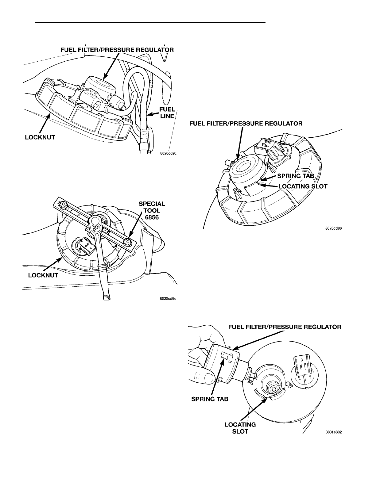
(7) Use Special Tool 6856 to remove fuel pump
(8) Remove fuel pump and O-ring seal from tank.
(1) Wipe seal area of tank clean and place a new
(2) Position fuel pump in the tank. Make sure the
(3) Position the locknut over the fuel pump mod-
Page 13
LOCKNUT
FUEL FILTER/PRESSURE REGULATORFUEL
SPECIAL TOOL 6856LOCKNUT
LINE
FUEL FILTER/PRESSURE REGULATOR
SPRING TABLOCATING SLOT
PL FUEL SYSTEM 14 - 13
REMOVAL AND INSTALLATION (Continued)
(2) Raise vehicle on hoist.
(3) Disconnect fuel supply line at the Filter/Regulator nipple (refer to Quick Connect Fittings in this
section).
(4) Depress locking spring tab on side of Fuel/Regulator (Fig. 19) and rotate 90° counter-clockwise and
pull out.
NOTE: Make sure that the upper and lower O-rings
are on the Filter/Regulator assembly.
Fig. 17 Fuel Pump Module Removal
(4) Tighten the locknut using Special Tool 6856 to
55 N·m (40.5 ft. lbs.) (Fig. 18).
Fig. 18 Fuel Tank Locknut
CAUTION: Over tightening the pump lock ring may
result in a leak.
(5) Fill fuel tank. Check for leaks.
FUEL FILTER / PRESSURE REGULATOR
REMOVAL
WARNING: THE FUEL SYSTEM IS UNDER A CONSTANT PRESSURE, EVEN WITH ENGINE OFF.
BEFORE SERVICING THE FUEL FILTER/FUEL
PRESSURE REGULATOR, THE FUEL SYSTEM
PRESSURE MUST BE RELEASED.
Fig. 19 Locking Spring Tab
INSTALLATION
Lightly lubricate the O-rings with engine oil.
(1) Insert Filter/Regulator into the opening in the
fuel pump module, align the two hold down tabs with
the flange.
(2) While applying downward pressure, rotate the
FUEL FILTER/PRESSURE REGULATORSPRING TABLOCATING SLOT
Filter/Regulator clockwise until the the spring tab
engages the locating slot (Fig. 20).
(3) Connect the fuel line to the Filter/Regulator.
(4) Lower vehicle from hoist.
(1) Refer to Fuel System Pressure Release in the
Fuel Delivery System section of this group.
The fuel filter/fuel pressure regulator is located on
the top of fuel pump module. Fuel pump module
removal is not necessary.
Fig. 20 Spring Tab In Locating Slot
Page 14
TABSINLET STRAINER
RETAINING TAB TANK SEALELECTRICAL CONNECTOR
WIRE TER-MINAL
LOCKINGFINGER
ELECTRICALCONNECTORBLUE LOCKING WEDGE
14 - 14 FUEL SYSTEM PL
REMOVAL AND INSTALLATION (Continued)
FUEL PUMP INLET STRAINER
REMOVAL
(1) Remove fuel pump module. Refer to Fuel Pump
Module Removal in this section.
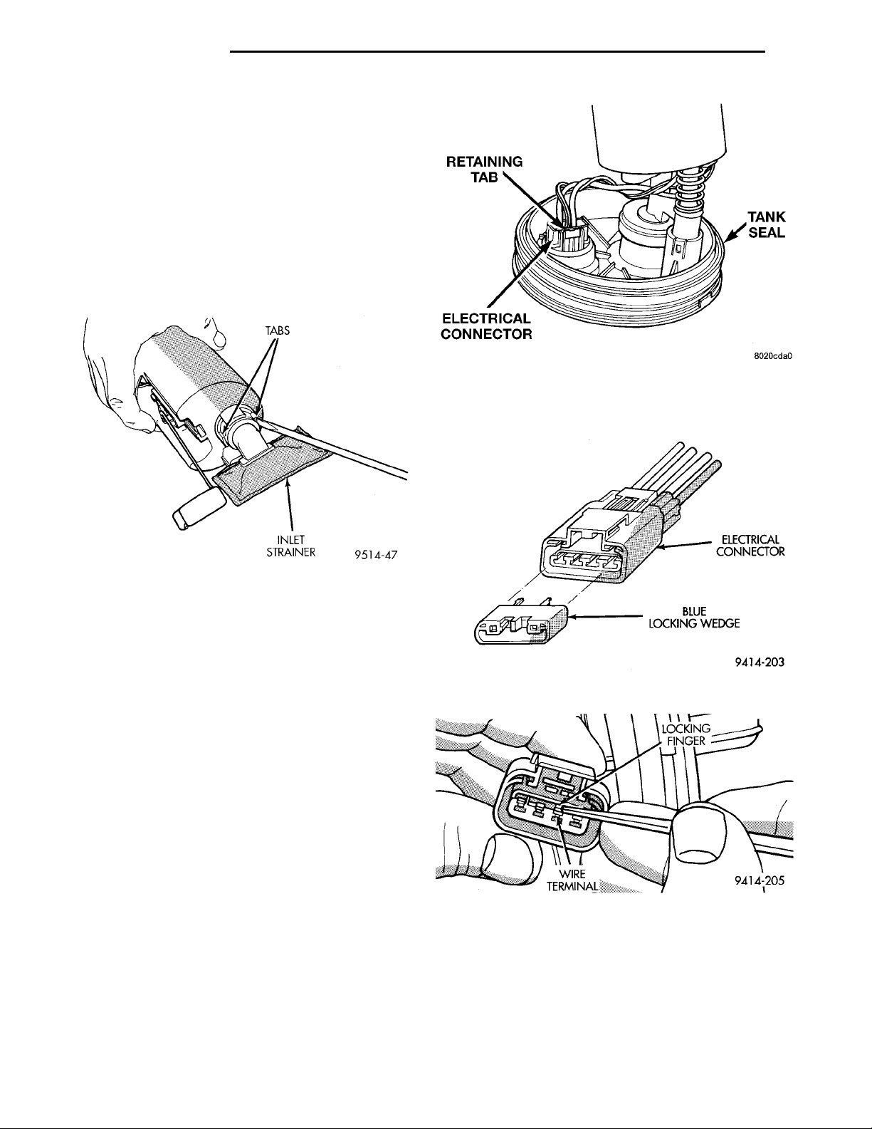
(2) Using a thin straight blade screwdriver, pry
back the locking tabs on fuel pump reservoir and
remove the strainer (Fig. 21).
(3) Remove strainer O-ring from the fuel pump
reservoir body.
(4) Remove any contaminants in the fuel tank by
washing the inside of the fuel tank.
Fig. 22 Fuel Pump/Level Sensor Electrical
Connector
Fig. 21 Inlet Strainer Removal
INSTALLATION
(1) Lubricate the strainer O-ring with clean engine
oil.
(2) Insert strainer O-ring into outlet of strainer so
that it sits evenly on the step inside the outlet.
(3) Push strainer onto the inlet of the fuel pump
reservoir body. Make sure the locking tabs on the
reservoir body lock over the locking tangs on the
strainer.
(4) Install fuel pump module. Refer to Fuel Pump
Module Installation in this section.
FUEL LEVEL SENSOR
REMOVAL
Remove fuel pump module. Refer to Fuel Pump
Module in this section.
(1) Depress retaining tab and remove the fuel
pump/level sensor connector from the bottom of the
fuel pump module electrical connector (Fig. 22).
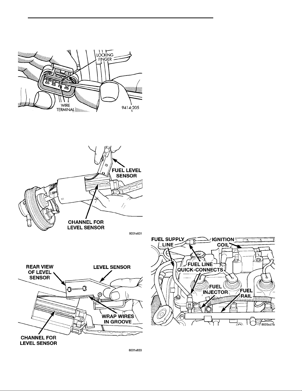
(2) Pull off blue locking wedge (Fig. 23).
(3) Using a small screwdriver lift locking finger
away from terminal and push terminal out of connector (Fig. 24).
Fig. 23 Wire Terminal Locking Wedge
Fig. 24 Wire Terminal Locking Finger
Page 15
REAR VIEW OF LEVEL SEN-SOR LEVEL SENSORWRAP WIRES INGROOVECHANNEL FOR LEVEL SEN-SOR
WIRE TER-MINAL
LOCKINGFINGER
FUEL LEVEL SEN-SORCHANNEL FOR LEVEL SEN-SOR
FUEL SUP-
PLY LINE
IGNITIONCOILFUEL LINE QUICKCONNECTSFUELINJECTOR
FUEL RAIL
PL FUEL SYSTEM 14 - 15
REMOVAL AND INSTALLATION (Continued)
(4) Push level sensor signal and ground terminals
out of the connector (Fig. 25).
Fig. 25 Removing Wires From Connector
(5) Insert a screwdriver between the fuel pump
module and the top of the level sensor housing (Fig.
26). Push level sensor down slightly.
(7) Slide level sensor out of installation channel in
module.
INSTALLATION
(1) Insert level sensor wires into bottom of opening
in module.
(2) Wrap wires into groove in back of level sensor
(Fig. 26).
(3) While feeding wires into guide grooves, slide
level sensor up into channel until it snaps into place
(Fig. 27). Ensure tab at bottom of sensor locks in
place.
(4) Install level sensor wires in connector. Push
the wires up through the connector and then pull
them down until they lock in place. Ensure signal
and ground wires are installed in the correct position.
(5) Install locking wedge on connector.
(6) Push connector up into bottom of fuel pump
module electrical connector.
(7) Install fuel pump module. Refer to Fuel Pump
Module in this section.
FUEL INJECTORS
Fig. 26 Loosening Level Sensor
(6) Slide level sensor wires through opening fuel
pump module (Fig. 27).
REMOVAL
(1) Disconnect negative cable from battery.
(2) Release fuel system pressure. Refer to Fuel
System Pressure Release procedure in this section.
(3) Disconnect fuel supply tube from rail. Refer to
Quick-Connect Fittings in the Fuel Delivery section
of this group.
(4) Disconnect electrical connectors from fuel injectors (Fig. 28).
Fig. 27 Level Sensor Removal/Installation
Fig. 28 Fuel Rail and Injectors
Page 16
14 - 16 FUEL SYSTEM PL
REMOVAL AND INSTALLATION (Continued)
RETAINER
FUEL INJECTOR NOZZLETOP (FUEL ENTRY)
FUEL INJECTOR
FUEL RAIL
(5) Remove fuel rail mounting screws.
(6) Lift rail off of intake manifold. Cover the fuel
injector openings in the intake manifold.
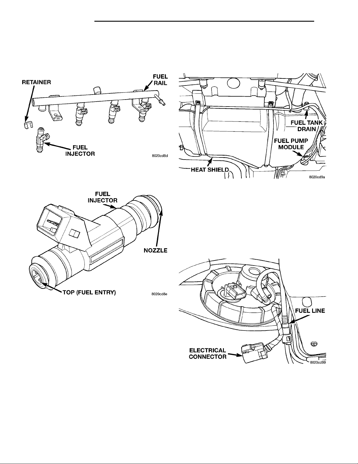
(7) Remove fuel injector retainer (Fig. 29).
Fig. 29 Fuel Injector Retainer
(8) Pull injector out of fuel rail. Replace fuel injec-
tor O-rings (Fig. 30).
FUEL TANKDRAINFUEL PUMP MOD-ULEHEAT SHIELD
FUEL TANK
ELECTRICAL CON-
REMOVAL
NECTOR
FUEL LINE
(1) Perform fuel system pressure release.
Fig. 31 Fuel Tank
(2) Drain fuel tank. Refer to Draining Fuel Tank
in this section (Fig. 31).
(3) Raise vehicle on hoist.
Fig. 30 Fuel Injector O-Rings
INSTALLATION
(1) Apply a light coating of clean engine oil to the
upper O-ring.
(2) Install injector in cup on fuel rail.
(3) Install retaining clip.
(4) Apply a light coating of clean engine oil to the
O-ring on the nozzle end of each injector.
(5) Insert fuel injector nozzles into openings in
intake manifold. Seat the injectors in place. Tighten
fuel rail mounting screws to 22.5 N·m 6 3 N·m
(200630 in. lbs.).
(6) Attach electrical connectors to fuel injectors.
(7) Connect fuel supply tube to fuel rail. Refer to
Quick Connect Fittings in the Fuel Delivery Section
of this Group.
WARNING: WRAP SHOP TOWELS AROUND
HOSES TO CATCH ANY GASOLINE SPILLAGE.
(4) Disconnect fuel pump module electrical connec-
tor (Fig. 32).
Fig. 32 Fuel Pump Module Electrical Connector
(5) Disconnect the fuel tube from Fuel Filter/Regulator. Refer to Quick Connect Fittings in the Fuel
Delivery section of this group.
(6) Support tank with transmission jack. Loosen
tank mounting straps and lower tank slightly.
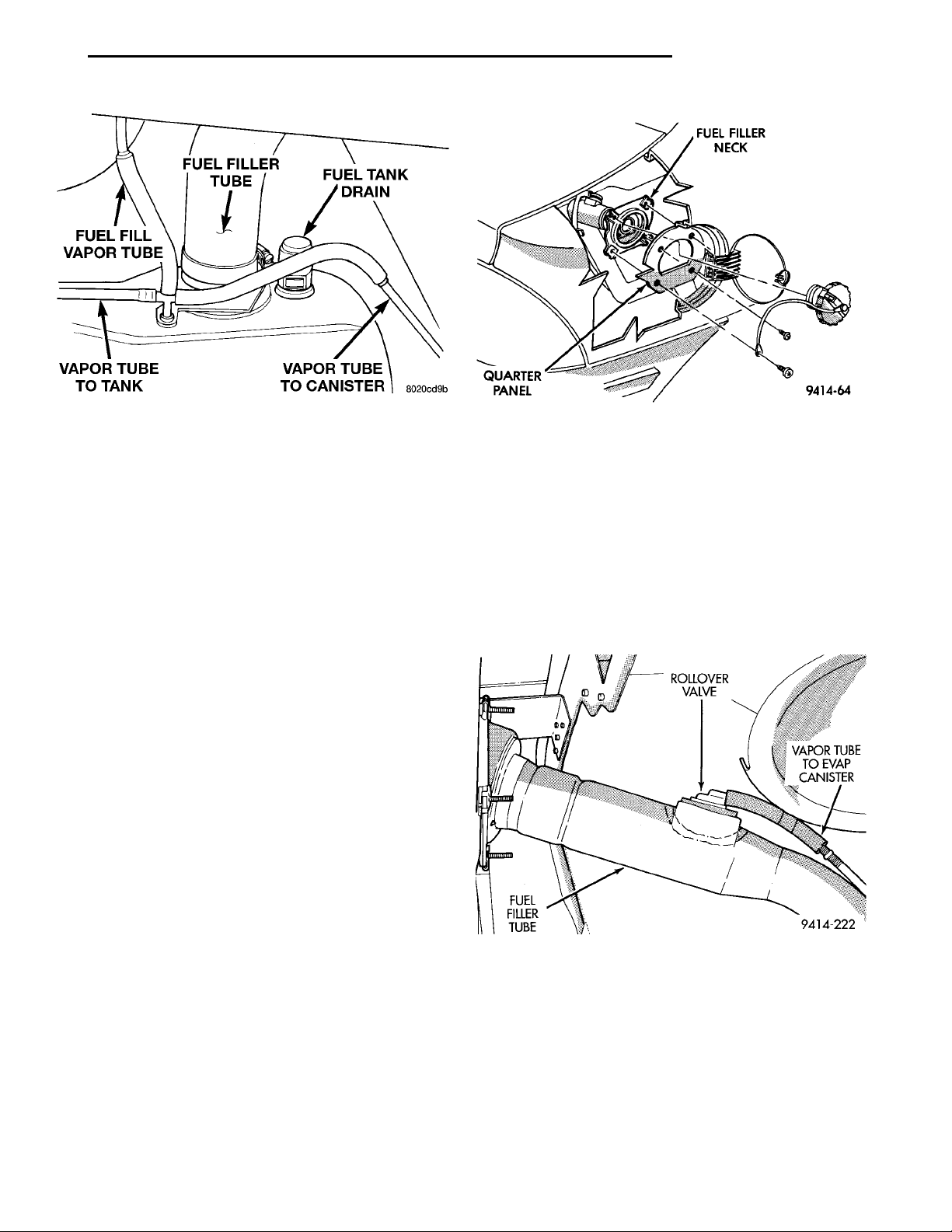
(7) Disconnect fuel filler tube and filler vent tube
from filler hose at fuel tank (Fig. 33).
Page 17
FUEL FILL VAPORTUBE FUEL FILLER TUBE FUEL TANK DRAINVAPOR TUBE TO CANISTERVAPOR TUBE TO TANK
FUEL FILLER NECKQUARTER PANEL
PL FUEL SYSTEM 14 - 17
REMOVAL AND INSTALLATION (Continued)
Fig. 33 Fuel Filler Tube and Vent Tubes
(8) Disconnect fuel filler vapor relief tube from tee
connecting it to the tank vapor relief tube and EVAP
canister tube.
(9) Disconnect vapor line from Evap canister tube.
(10) Remove tank mounting straps and lower tank.
INSTALLATION
(1) Position fuel tank on transmission jack.
(2) Raise tank into position. Connect fuel filler
tube tank inlet nipple.
(3) Tighten fuel tank strap nuts to 23 N·m (250 in.
lbs.) torque. Remove transmission jack. Ensure
straps are not twisted or bent.
(4) Attach fuel tubes to pump module and chassis
fuel tube. Refer to Quick Connect Fittings in the Fuel
Delivery section of this Group.
(5) Connect fuel vapor tube to tee, then to Evap
canister tube.
(6) Attach electrical connector to fuel pump module.
(7) Lower vehicle.
(8) Fill fuel tank, install filler cap, and connect
battery cable.
FUELFILLERTUBE
ROLLOVER VALVE
VAPOR TUBE
TO EVAP CAN-
Fig. 34 Fuel Filler Neck
(4) Disconnect fuel filler tube from fuel tank.
Remove filler neck.
INSTALLATION
(1) Reverse for installation.
FUEL FILLER TUBE ROLLOVER VALVE
REMOVAL
The rollover valve is mounted in the fuel filler tube
(Fig. 35).
ISTER
CAUTION: When using the ASD Fuel System Test,
the Auto Shutdown (ASD) Relay remains energized
for either 7 minutes, until the test is stopped, or
until the ignition switch is turned to the Off position.
(9) Use the DRB scan tool ASD Fuel System Test
to pressurize the fuel system. Check for leaks.
FUEL FILLER NECK
REMOVAL
(1) Loosen fuel filler tube cap.
(2) Remove fuel filler neck screws (Fig. 34).
(3) Disconnect fuel fill vapor tube.
Fig. 35 Fuel Filler Tube Rollover Valve
(1) To release fuel tank pressure, remove the fuel
filler tube cap.
(2) Disconnect vapor tube from rollover valve.
(3) Using a straight screwdriver, pry the valve out
of the grommet in the fuel filler tube.
INSTALLATION
(1) Apply a light coating of power steering fluid to
the grommet.
(2) Install valve in grommet.
Page 18
GROMMET CABLEPEDAL SHAFTAND BRACKETSEALDASHPANELCABLE ASSEM-BLY
RETAINER CLIP GROMMETCABLE ASSEM-BLY CABLERETAINERDASH PANELGROMMET
MOUNTING TABTHROTTLE CONTROLSHIELDMOUNTING SCREW
14 - 18 FUEL SYSTEM PL
REMOVAL AND INSTALLATION (Continued)
(3) Attach vapor tube to valve.
(4) Install fuel filler tube cap.
ACCELERATOR PEDAL
CAUTION: When servicing the accelerator pedal,
throttle cable or speed control cable, do not damage or kink the core wire inside the cable sheathing.
REMOVAL
(1) Working from the engine compartment, remove
the throttle control shield.
(2) Hold the throttle body throttle lever in the
wide open position. Remove the throttle cable from
the throttle body cam.
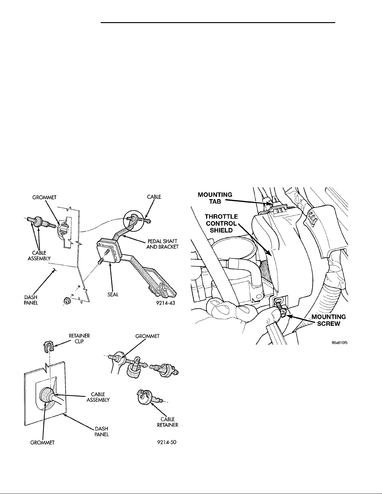
(3) From inside the vehicle, hold up the pedal and
remove the cable retainer and throttle cable from the
upper end of the pedal shaft (Fig. 36) and (Fig. 37).
(4) Working from the engine compartment, remove
nuts from accelerator pedal attaching studs (Fig. 36).
Remove assembly from vehicle.
INSTALLATION
(1) Position accelerator pedal assembly on dash
panel. Install retaining nuts. Tighten retaining nuts
to 12 N·m (105 in. lbs.) torque.
(2) From inside the vehicle, hold up the pedal and
install the throttle cable and cable retainer in the
upper end of the pedal shaft.
(3) From the engine compartment, hold the throttle body lever in the wide open position and install
the throttle cable. Install the throttle control shield.
THROTTLE CABLE—MANUAL TRANSMISSION
REMOVAL
(1) Remove throttle control shield (Fig. 38).
Fig. 36 Accelerator Pedal and Throttle Cable—Front
View
Fig. 37 Accelerator Pedal and Throttle Cable—Rear
View
Fig. 38 Throttle Control Shield
(2) Working from the engine compartment, remove
the throttle cable from the throttle body lever (Fig.
39) and (Fig. 40).
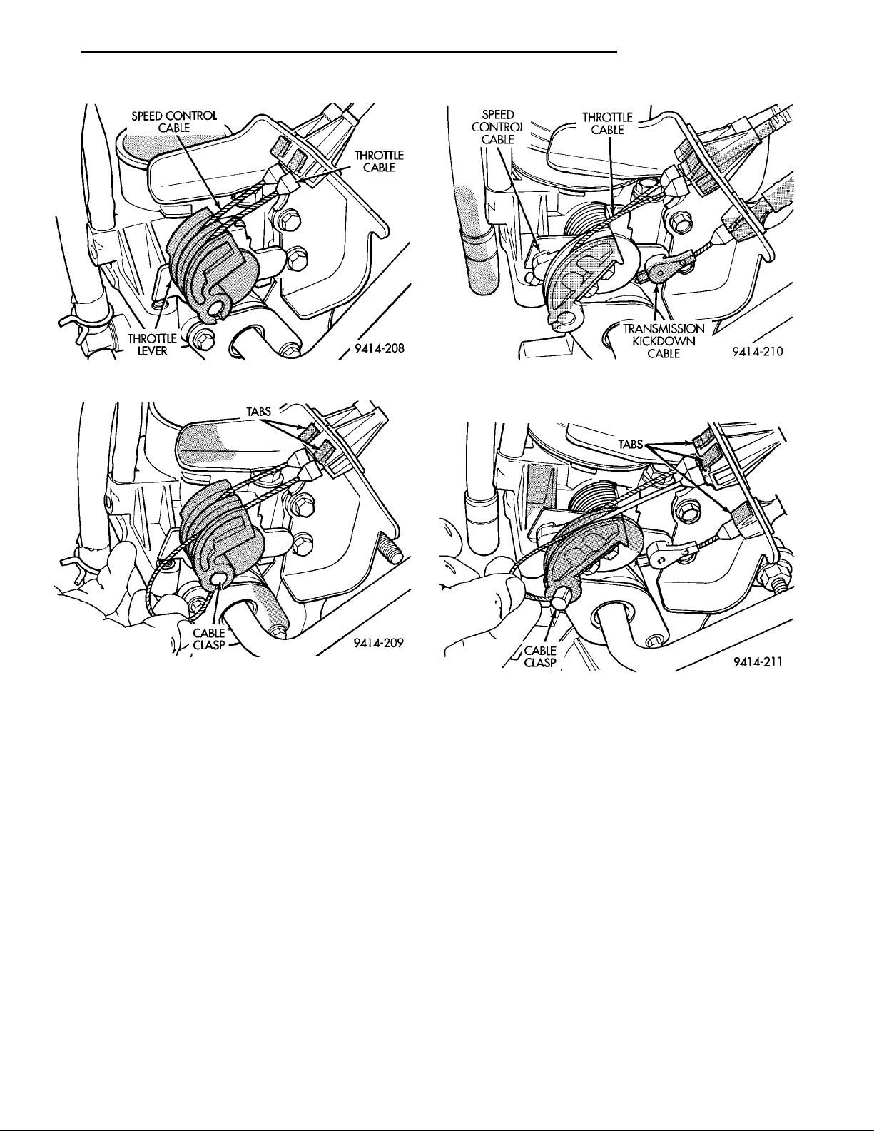
(3) Compress the retaining tabs on the cable and
slide cable out of bracket.
(4) From inside the vehicle, hold the accelerator
pedal up and remove the cable retainer and cable
from upper end of pedal shaft (Fig. 36) and (Fig. 37).
(5) Remove retainer clip from throttle cable and
grommet at the dash panel.
(6) From the engine compartment, pull the throttle
cable out of the dash panel grommet. The grommet
should remain in the dash panel.
Page 19
SPEED CONTROLCABLE THROTTLECABLETHROTTLELEVER
SPEED CON-TROL CABLE THROTTLECABLETRANSMISSIONKICKDOWNCABLE
TABSCABLECLASP
PL FUEL SYSTEM 14 - 19
REMOVAL AND INSTALLATION (Continued)
CLASP
TABSCABLE
Fig. 39 Throttle Cable Attachment to Throttle Body
Fig. 40 Disconnecting Throttle Cable
INSTALLATION
(1) From the engine compartment, push the hous-
ing end fitting into the dash panel grommet.
(2) Install cable housing (throttle body end) into
the cable mounting bracket on the engine.
(3) From inside the vehicle, hold up pedal and feed
throttle cable core wire through hole in upper end of
the pedal shaft. Install cable retainer.
(4) Install cable retainer clip.
(5) From the engine compartment, rotate the
throttle lever forward to the wide open position and
install cable clasp (Fig. 40).
(6) Install throttle control shield (Fig. 38). Tighten
screw to 5.6 N·m (50 in. lbs.).
THROTTLE CABLE—AUTOMATIC TRANSMISSION
REMOVAL
(1) Remove throttle control shield (Fig. 38).
(2) Working from the engine compartment, remove
throttle cable from throttle body cam (Fig. 41) and
(Fig. 42).
Fig. 41 Throttle Body Cables Attachment to Throttle
Body
Fig. 42 Disconnecting Throttle Cable
(3) Compress the retaining tabs on the cable and
slide cable out of bracket.
(4) From inside the vehicle, hold the throttle pedal
up and remove the cable retainer and cable from
upper end of pedal shaft (Fig. 36) and (Fig. 37).
(5) Remove retainer clip from throttle cable and
grommet at the dash panel.
(6) From the engine compartment, pull the throttle
cable out of the dash panel grommet. The grommet
should remain in the dash panel.
INSTALLATION
(1) From the engine compartment, push the housing end fitting into the dash panel grommet.
(2) Install cable housing (throttle body end) into
the cable mounting bracket on the engine.
(3) From inside the vehicle, hold up pedal and feed
throttle cable core wire through hole in upper end of
the pedal shaft. Install cable retainer (Fig. 37).
(4) Install cable retainer clip.
Page 20

14 - 20 FUEL SYSTEM PL
REMOVAL AND INSTALLATION (Continued)
(5) From the engine compartment, rotate the
throttle lever forward to the wide open position and
install cable clasp (Fig. 42).
(6) Install throttle ontrol shield (Fig. 38). Tighten
to 5.6 N·m (50 in. lbs.).
SPECIFICATIONS
TORQUE SPECIFICATION
DESCRIPTION TORQUE
Accelerator Pedal to Dash Nuts . 12 N·m (105 in. lbs.)
Fuel Pump Module Locknut ....55N·m(40ft.lbs.)
Fuel Tank Strap Bolts .......23N·m(250 in. lbs.)
Fuel Rail Bolts .............23N·m(195 in. lbs.)
Ignition Coil Mounting Bolts . . . 11 N·m (95 in. lbs.)
Intake Manifold Bolts ........11N·m(95in.lbs.)
Throttle Control Shield .......5.6N·m(50in.lbs.)
Page 21

PL FUEL SYSTEM 14 - 21
FUEL INJECTION SYSTEM
INDEX
page page
GENERAL INFORMATION
INTRODUCTION ....................... 22
MODES OF OPERATION ................. 22
DESCRIPTION AND OPERATION
AIR CONDITIONING CLUTCH RELAY—PCM
OUTPUT ............................ 33
AIR CONDITIONING PRESSURE
TRANSDUCER—PCM INPUT ............ 26
AUTOMATIC SHUTDOWN (ASD) SENSE—PCM
INPUT .............................. 26
AUTOMATIC SHUTDOWN RELAY—PCM
OUTPUT ............................ 33
BATTERY TEMPERATURE SENSOR—PCM
INPUT .............................. 26
BATTERY VOLTAGE—PCM INPUT .......... 26
BRAKE SWITCH—PCM INPUT ............. 26
CAMSHAFT POSITION SENSOR—PCM
INPUT .............................. 27
CHARGING SYSTEM INDICATOR LAMP—PCM
OUTPUT ............................ 33
CRANKSHAFT POSITION SENSOR—PCM
INPUT .............................. 27
DATA LINK CONNECTOR ................. 35
DUTY CYCLE EVAP PURGE SOLENOID—PCM
OUTPUT ............................ 34
ELECTRIC EGR TRANSDUCER—PCM
OUTPUT ............................ 34
ENGINE COOLANT TEMPERATURE SENSOR—
PCM INPUT ......................... 28
FUEL INJECTORS—PCM OUTPUT ......... 35
FUEL LEVEL SENSOR—PCM INPUT ........ 29
FUEL PUMP RELAY—PCM OUTPUT ........ 34
GENERATOR FIELD—PCM OUTPUT ........ 34
HEATED OXYGEN SENSOR (O2S SENSOR)—
PCM INPUT ......................... 29
IDLE AIR CONTROL MOTOR—PCM OUTPUT . 34
IGNITION CIRCUIT SENSE—PCM INPUT .... 30
IGNITION COIL—PCM OUTPUT ............ 36
INTAKE AIR TEMPERATURE SENSOR—PCM
INPUT .............................. 30
KNOCK SENSOR—PCM INPUT ............ 31
MALFUNCTION INDICATOR (CHECK ENGINE)
LAMP—PCM OUTPUT ................. 36
MANIFOLD ABSOLUTE PRESSURE (MAP)
SENSOR—PCM INPUT ................. 31
PARK/NEUTRAL POSITION SWITCH—PCM
INPUT .............................. 32
POWER DISTRIBUTION CENTER .......... 25
POWER STEERING PRESSURE SWITCH—
PCM INPUT ......................... 31
POWERTRAIN CONTROL MODULE ......... 25
RADIATOR FAN CONTROL MODULE—PCM
OUTPUT ............................ 36
SCI RECEIVE—PCM INPUT ............... 32
SCI RECEIVE—PCM INPUT ............... 37
SENSOR RETURN—PCM INPUT ........... 31
SPEED CONTROL—PCM INPUT ........... 31
SPEED CONTROL—PCM INPUT ........... 37
SYSTEM DIAGNOSIS .................... 24
TACHOMETER—PCM OUTPUT ............ 37
THROTTLE POSITION SENSOR—PCM
INPUT .............................. 32
TORQUE CONVERTOR CLUTCH SOLENOID—
PCM OUTPUT ........................ 37
VEHICLE SPEED SENSOR—PCM INPUT .... 33
DIAGNOSIS AND TESTING
ASD AND FUEL PUMP RELAYS ............ 47
CAMSHAFT AND CRANKSHAFT POSITION
SENSOR ............................ 47
ENGINE COOLANT TEMPERATURE SENSOR . 48
HEATED OXYGEN SENSOR .............. 48
IDLE AIR CONTROL (IAC) MOTOR TEST ..... 48
KNOCK SENSOR ....................... 48
MANIFOLD ABSOLUTE PRESSURE (MAP)
SENSOR ............................ 48
THROTTLE BODY MINIMUM AIR FLOW ..... 49
THROTTLE POSITION SENSOR ........... 49
VEHICLE SPEED SENSOR ............... 50
VISUAL INSPECTION—DOHC ............. 42
VISUAL INSPECTION—SOHC ............. 37
REMOVAL AND INSTALLATION
AIR CLEANER ELEMENT ................. 56
CAMSHAFT POSITION SENSOR ........... 55
CRANKSHAFT POSITION SENSOR ......... 55
DOWNSTREAM HEATED OXYGEN SENSOR . 56
DUTY CYCLE EVAP PURGE SOLENOID
VALVE .............................. 54
ENGINE COOLANT TEMPERATURE SENSOR . 57
IDLE AIR CONTROL MOTOR .............. 53
KNOCK SENSOR ....................... 58
MAP/IAT SENSOR—DOHC ................ 54
MAP/IAT SENSOR—SOHC ................ 53
POWERTRAIN CONTROL MODULE (PCM) . . . 54
THROTTLE BODY—AUTOMATIC
TRANSMISSION ...................... 51
Page 22

14 - 22 FUEL SYSTEM PL
SPECIFICATIONS (Continued)
THROTTLE BODY—MANUAL
TRANSMISSION ...................... 50
THROTTLE POSITION SENSOR (TPS) ...... 52
UPSTREAM HEATED OXYGEN SENSOR .... 55
VEHICLE SPEED SENSOR ............... 58
GENERAL INFORMATION
INTRODUCTION
All engines used in this section have a sequential
Multi-Port Electronic Fuel Injection system. The MPI
system is computer regulated and provides precise
air/fuel ratios for all driving conditions. The Powertrain Control Module (PCM) operates the fuel injection system.
The PCM regulates:
• Ignition timing
• Air/fuel ratio
• Emission control devices
• Cooling fan
• Charging system
• Idle speed
• Vehicle speed control
Various sensors provide the inputs necessary for
the PCM to correctly operate these systems. In addition to the sensors, various switches also provide
inputs to the PCM.
All inputs to the PCM are converted into signals.
The PCM can adapt its programming to meet changing operating conditions.
Fuel is injected into the intake port above the
intake valve in precise metered amounts through
electrically operated injectors. The PCM fires the
injectors in a specific sequence. Under most operating conditions, the PCM maintains an air fuel ratio
of 14.7 parts air to 1 part fuel by constantly adjusting injector pulse width. Injector pulse width is the
length of time the injector is open.
The PCM adjusts injector pulse width by opening
and closing the ground path to the injector. Engine
RPM (speed) and manifold absolute pressure (air
density) are the primary inputs that determine injector pulse width.
MODES OF OPERATION
As input signals to the PCM change, the PCM
adjusts its response to output devices. For example,
the PCM must calculate a different injector pulse
width and ignition timing for idle than it does for
Wide Open Throttle (WOT). There are several different modes of operation that determine how the PCM
responds to the various input signals.
There are two different areas of operation, OPEN
LOOP and CLOSED LOOP.
During OPEN LOOP modes the PCM receives
input signals and responds according to preset PCM
SPECIFICATIONS
TORQUE SPECIFICATIONS ............... 58
VECI LABEL ........................... 58
SPECIAL TOOLS
FUEL ................................ 59
programming. Inputs from the upstream and downstream heated oxygen sensors are not monitored during OPEN LOOP modes, except for heated oxygen
sensor diagnostics (they are checked for shorted conditions at all times).
During CLOSED LOOP modes the PCM monitors
the inputs from the upstream and downstream
heated oxygen sensors. The upstream heated oxygen
sensor input tells the PCM if the calculated injector
pulse width resulted in the ideal air-fuel ratio of 14.7
to one. By monitoring the exhaust oxygen content
through the upstream heated oxygen sensor, the
PCM can fine tune injector pulse width. Fine tuning
injector pulse width allows the PCM to achieve optimum fuel economy combined with low emissions.
For the PCM to enter CLOSED LOOP operation,
the following must occur:
(1) Engine coolant temperature must be over 35°F.
• If the coolant is over 35° the PCM will wait 44
seconds.
• If the coolant is over 50°F the PCM will wait 38
seconds.
• If the coolant is over 167°F the PCM will wait
11 seconds.
(2) For other temperatures the PCM will interpolate the correct waiting time.
(3) O2 sensor must read either greater than .745
volts or less than .1 volt.
(4) The multi-port fuel injection systems has the
following modes of operation:
• Ignition switch ON (Zero RPM)
• Engine start-up
• Engine warm-up
• Cruise
• Idle
• Acceleration
• Deceleration
• Wide Open Throttle
• Ignition switch OFF
(5) The engine start-up (crank), engine warm-up,
deceleration with fuel shutoff and wide open throttle
modes are OPEN LOOP modes. Under most operating conditions, the acceleration, deceleration (with
A/C on), idle and cruise modes, with the engine at
operating temperature are CLOSED LOOP modes.
IGNITION SWITCH ON (ZERO RPM) MODE
When the ignition switch activates the fuel injection system, the following actions occur:
Page 23

PL FUEL SYSTEM 14 - 23
GENERAL INFORMATION (Continued)
• The PCM monitors the engine coolant temperature sensor and throttle position sensor input. The
PCM determines basic fuel injector pulse width from
this input.
• The PCM determines atmospheric air pressure
from the MAP sensor input to modify injector pulse
width.
When the key is in the ON position and the engine
is not running (zero rpm), the Auto Shutdown (ASD)
and fuel pump relays de-energize after approximately
1 second. Therefore, battery voltage is not supplied to
the fuel pump, ignition coil, fuel injectors and heated
oxygen sensors.
ENGINE START-UP MODE
This is an OPEN LOOP mode. If the vehicle is in
park or neutral (automatic transaxles) or the clutch
pedal is depressed (manual transaxles) the ignition
switch energizes the starter relay. The following
actions occur when the starter motor is engaged.
• If the PCM receives the camshaft position sensor
and crankshaft position sensor signals, it energizes
the Auto Shutdown (ASD) and fuel pump relays. If
the PCM does not receive both signals within approximately one second, it will not energize the ASD
relay and fuel pump relay. The ASD and fuel pump
relays supply battery voltage to the fuel pump, fuel
injectors, ignition coil and heated oxygen sensors.
• The PCM energizes all four injectors (on the 69°
degree falling edge) for a calculated pulse width until
it determines crankshaft position from the camshaft
position sensor and crankshaft position sensor signals. The PCM determines crankshaft position within
1 engine revolution.
• After determining crankshaft position, the PCM
begins energizing the injectors in sequence. It adjusts
injector pulse width and controls injector synchronization by turning the individual ground paths to the
injectors On and Off.
• When the engine idles within 664 RPM of its
target RPM, the PCM compares current MAP sensor
value with the atmospheric pressure value received
during the Ignition Switch On (zero RPM) mode. If
the PCM does not detect a minimum difference
between the two values, it sets a MAP diagnostic
trouble code into memory.
Once the ASD and fuel pump relays have been
energized, the PCM determines injector pulse width
based on the following:
• Battery voltage
• Engine coolant temperature
• Engine RPM
• Intake air temperature (IAT)
• Throttle position
• The number of engine revolutions since cranking
was initiated
During Start-up the PCM maintains ignition tim-
ing at 9° BTDC.
ENGINE WARM-UP MODE
This is an OPEN LOOP mode. The following inputs
are received by the PCM:
• Engine coolant temperature
• Manifold Absolute Pressure (MAP)
• Intake air temperature (IAT)
• Crankshaft position (engine speed)
• Camshaft position
• Knock sensor
• Throttle position
• A/C switch
• Battery voltage
• Power steering pressure switch
• Vehicle speed
• Speed control
• Both O2 sensors
• All diagnostics
The PCM adjusts injector pulse width and controls
injector synchronization by turning the individual
ground paths to the injectors On and Off.
The PCM adjusts ignition timing and engine idle
speed. Engine idle speed is adjusted through the idle
air control motor.
CRUISE OR IDLE MODE
When the engine is at operating temperature this
is a CLOSED LOOP mode. During cruising or idle
the following inputs are received by the PCM:
• Intake air temperature
• Engine coolant temperature
• Manifold absolute pressure
• Crankshaft position (engine speed)
• Camshaft position
• Knock sensor
• Throttle position
• Exhaust gas oxygen content
• A/C control positions
• Power steering pressure switch
• Battery voltage
• Vehicle speed
The PCM adjusts injector pulse width and controls
injector synchronization by turning the individual
ground paths to the injectors On and Off.
The PCM adjusts engine idle speed and ignition
timing. The PCM adjusts the air/fuel ratio according
to the oxygen content in the exhaust gas (measured
by the upstream and downstream heated oxygen sensor).
The PCM monitors for engine misfire. During
active misfire and depending on the severity, the
PCM either continuously illuminates or flashes the
malfunction indicator lamp (Check Engine light on
instrument panel). Also, the PCM stores an engine
misfire DTC in memory.
Page 24

14 - 24 FUEL SYSTEM PL
GENERAL INFORMATION (Continued)
The PCM performs several diagnostic routines.
They include:
• Oxygen sensor monitor
• Downstream heated oxygen sensor diagnostics
during open loop operation (except for shorted)
• Fuel system monitor
• EGR monitor
• Purge system monitor
• All inputs monitored for proper voltage range.
• All monitored components (refer to Group 25 for
On-Board Diagnostics).
The PCM compares the upstream and downstream
heated oxygen sensor inputs to measure catalytic
convertor efficiency. If the catalyst efficiency drops
below the minimum acceptable percentage, the PCM
stores a diagnostic trouble code in memory.
During certain idle conditions, the PCM may enter
a variable idle speed strategy. During variable idle
speed strategy the PCM adjusts engine speed based
on the following inputs.
• A/C sense
• Battery voltage
• Battery temperature
• Engine coolant temperature
• Engine run time
• Power steering pressure switch
• Vehicle mileage
ACCELERATION MODE
This is a CLOSED LOOP mode. The PCM recognizes an abrupt increase in Throttle Position sensor
output voltage or MAP sensor output voltage as a
demand for increased engine output and vehicle
acceleration. The PCM increases injector pulse width
in response to increased fuel demand.
DECELERATION MODE
This is a CLOSED LOOP mode. During deceleration the following inputs are received by the PCM:
• A/C pressure transducer
• A/C sense
• Battery voltage
• Intake air temperature
• Engine coolant temperature
• Crankshaft position (engine speed)
• Exhaust gas oxygen content (upstream heated
oxygen sensor)
• Knock sensor
• Manifold absolute pressure
• Power steering pressure switch
• Throttle position
• IAC motor control changes in respones to MAP
sensor feedback
The PCM may receive a closed throttle input from
the Throttle Position Sensor (TPS) when it senses an
abrupt decrease in manifold pressure. This indicates
a hard deceleration. In response, the PCM may
momentarily turn off the injectors. This helps
improve fuel economy, emissions and engine braking.
If decel fuel shutoff is detected, downstream oxygen sensor diagnostics is performed.
WIDE-OPEN-THROTTLE MODE
This is an OPEN LOOP mode. During wide-openthrottle operation, the following inputs are received
by the PCM:
• Intake air temperature
• Engine coolant temperature
• Engine speed
• Knock sensor
• Manifold absolute pressure
• Throttle position
When the PCM senses a wide-open-throttle condition through the Throttle Position Sensor (TPS) it deenergizes the A/C compressor clutch relay. This
disables the air conditioning system.
The PCM does not monitor the heated oxygen sensor inputs during wide-open-throttle operation except
for downstream heated oxygen sensor and both
shorted diagnostics. The PCM adjusts injector pulse
width to supply a predetermined amount of additional fuel.
IGNITION SWITCH OFF MODE
When the operator turns the ignition switch to the
OFF position, the following occurs:
• All outputs are turned off, unless 02 Heater
Monitor test is being run. Refer to Group 25,
On-Board Diagnostics.
• No inputs are monitored except for the heated
oxygen sensors. The PCM monitors the heating elements in the oxygen sensors and then shuts down.
DESCRIPTION AND OPERATION
SYSTEM DIAGNOSIS
The PCM can test many of its own input and output circuits. If the PCM senses a fault in a major
system, the PCM stores a Diagnostic Trouble Code
(DTC) in memory.
Technicians can display stored DTC’s by two different methods.
For DTC information, refer to Group 25, Emission
Control Systems. See On-Board Diagnostics.
Page 25
PL FUEL SYSTEM 14 - 25
DESCRIPTION AND OPERATION (Continued)
POWER DISTRIBUTION CENTER
POWER DISTRI-BUTION CEN-TER FUSESRELAYS
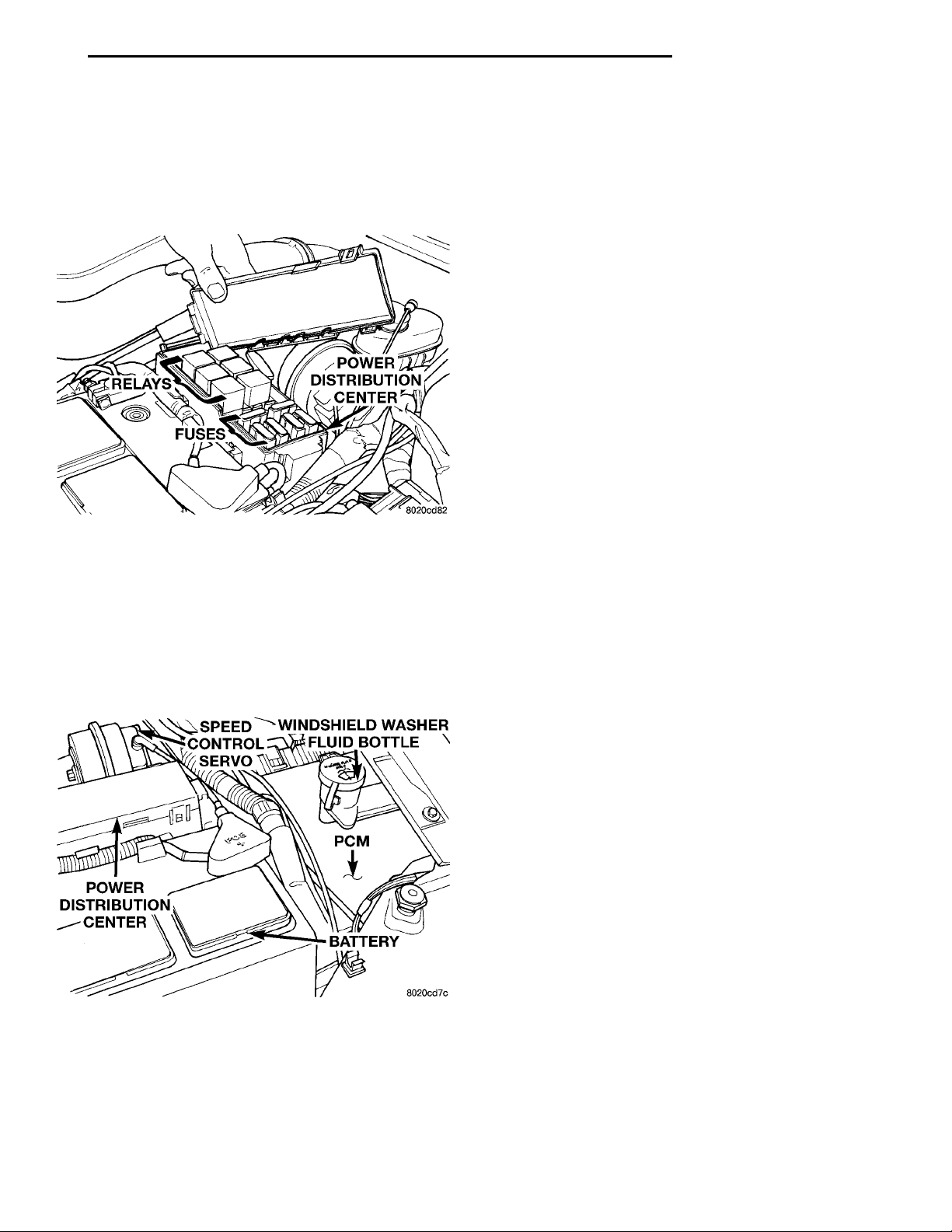
The power distribution center (PDC) is located next
to the battery (Fig. 1). The PDC contains the starter
relay, radiator fan relay, A/C compressor clutch relay,
auto shutdown relay, fuel pump relay and several
fuses.
Fig. 1 Power Distribution Center (PDC)
SPEED CON-TROL SERVO WINDSHIELDWASHER FLUIDBOTTLEPCMBATTERYPOWER DISTRI-BUTION CEN-TER
POWERTRAIN CONTROL MODULE
The Powertrain Control Module (PCM) is a digital
computer containing a microprocessor (Fig. 2). The
PCM receives input signals from various switches
and sensors that are referred to as PCM Inputs.
Based on these inputs, the PCM adjusts various
engine and vehicle operations through devices that
are referred to as PCM Outputs.
Fig. 2 Powertrain Control Module (PCM)
PCM Inputs:
• Air Conditioning Controls
• Battery Voltage
• Battery Temperature Sensor
• Brake Switch
• Camshaft Position Sensor
• Crankshaft Position Sensor
• Engine Coolant Temperature Sensor
• Fuel Level Sensor
• Ignition Switch
• Intake Air Temperature Sensor
• Knock Sensor
• Manifold Absolute Pressure (MAP) Sensor
• Oxygen Sensors
• Power Steering Pressure Switch
• SCI Receive
• Speed Control Switches
• Throttle Position Sensor
• Transmission Park/Neutral Switch (automatic
transmission)
• Vehicle Speed Sensor
PCM Outputs:
• Air Conditioning WOT Relay
• Auto Shutdown (ASD) Relay
• Charging Indicator Lamp
• Data Link Connector
• Duty Cycle EVAP Canister Purge Solenoid
• EGR Solenoid
• Fuel Injectors
• Fuel Pump Relay
• Generator Field
• Idle Air Control Motor
• Ignition Coils
• Malfunction Indicator (Check Engine) Lamp
• Radiator Fan Relay
• Speed Control Solenoids
• Tachometer
• Torque Convertor Clutch Solenoid
Based on inputs it receives, the PCM adjusts fuel
injector pulse width, idle speed, ignition spark
advance, ignition coil dwell and EVAP canister purge
operation. The PCM regulates the cooling fan, air
conditioning and speed control systems. The PCM
changes generator charge rate by adjusting the generator field. The PCM also performs diagnostics.
The PCM adjusts injector pulse width (air-fuel
ratio) based on the following inputs.
• Battery voltage
• Coolant temperature
• Intake air temperature
• Exhaust gas content (oxygen sensor)
• Engine speed (crankshaft position sensor)
• Manifold absolute pressure
• Throttle position
The PCM adjusts ignition timing based on the following inputs.
• Coolant temperature
• Intake air temperature
• Engine speed (crankshaft position sensor)
• Knock sensor
• Manifold absolute pressure
• Throttle position
Page 26

14 - 26 FUEL SYSTEM PL
DESCRIPTION AND OPERATION (Continued)
• Transmission gear selection (park/neutral
switch)
The PCM also adjusts engine idle speed through
the idle air control motor based on the following
inputs.
• Air conditioning sense
• Battery voltage
• Battery temperature
• Brake switch
• Coolant temperature
• Engine speed (crankshaft position sensor)
• Engine run time
• Manifold absolute pressure
• Power steering pressure switch
• Throttle position
• Transmission gear selection (park/neutral
switch)
• Vehicle distance (speed)
The Auto Shutdown (ASD) and fuel pump relays
are mounted externally, but turned on and off by the
PCM.
The crankshaft position sensor signal is sent to the
PCM. If the PCM does not receive the signal within
approximately one second of engine cranking, it deactivates the ASD relay and fuel pump relay. When
these relays deactivate, power is shut off from the
fuel injectors, ignition coils, heating element in the
oxygen sensors and the fuel pump.
The PCM contains a voltage converter that
changes battery voltage to a regulated 9 volts direct
current to power the camshaft position sensor, crankshaft position sensor and vehicle speed sensor. The
PCM also provides a 5 volt direct current supply for
the manifold absolute pressure sensor and throttle
position sensor.
AUTOMATIC SHUTDOWN (ASD) SENSE—PCM INPUT
The ASD sense circuit informs the PCM when the
ASD relay energizes. A 12 volt signal at this input
indicates to the PCM that the ASD has been activated. This input is used only to sense that the ASD
relay is energized.
When energized, the ASD relay supplies battery
voltage to the fuel injectors, ignition coils and the
heating element in each oxygen sensor. If the PCM
does not receive 12 volts from this input after
grounding the ASD relay, it sets a Diagnostic Trouble
Code (DTC).
BATTERY VOLTAGE—PCM INPUT
The PCM monitors the battery voltage input to
determine fuel injector pulse width and generator
field control.
If battery voltage is low the PCM will increase
injector pulse width (period of time that the injector
is energized).
BATTERY TEMPERATURE SENSOR—PCM INPUT
The PCM uses the temperature of the battery area
to control the charge rate. The signal is used to regulate the system voltage. The system voltage is
higher at cold temperatures and is gradually reduced
as temperature is increased.
BRAKE SWITCH—PCM INPUT
When the brake switch is activated, the PCM
receives an input indicating that the brakes are
being applied. The brake switch is mounted on the
brake pedal support bracket.
AIR CONDITIONING PRESSURE TRANSDUCER— PCM INPUT
The Powertrain Control Module (PCM) monitors
the A/C compressor discharge (high side) pressure
through the air conditioning pressure transducer.
The transducer supplies an input to the PCM. The
PCM engages the A/C compressor clutch if pressure
is sufficient for A/C system operation.
Page 27
PL FUEL SYSTEM 14 - 27
DESCRIPTION AND OPERATION (Continued)
CAMSHAFT POSITION SENSOR—PCM INPUT
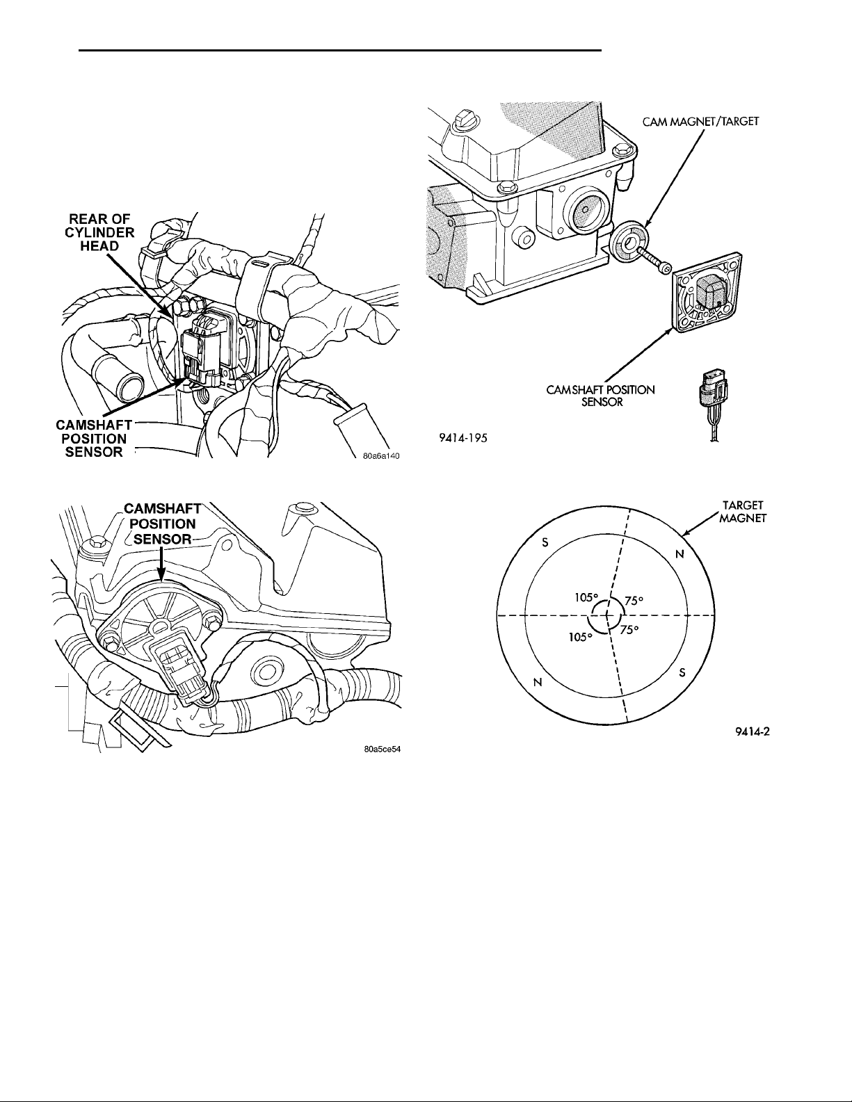
The PCM determines fuel injection synchronization
and cylinder identification from inputs provided by
the camshaft position sensor (Fig. 3) or (Fig. 4) and
crankshaft position sensor. From the two inputs, the
PCM determines crankshaft position.
CAMSHAFT POSITION SEN-SOR
Fig. 3 Camshaft Position Sensor—SOHC
Fig. 4 Camshaft Position Sensor—DOHC
The camshaft position sensor attaches to the rear
of the cylinder head. A target magnet attaches to the
rear of the camshaft and indexes to the correct position. The target magnet has four different poles
arranged in an asymmetrical pattern (Fig. 5). As the
target magnet rotates, the camshaft position sensor
senses the change in polarity (Fig. 6). The sensor output switch switches from high (5.0 volts) to low (0.5
volts) as the target magnet rotates. When the north
pole of the target magnet passes under the sensor,
the output switches high. The sensor output switches
low when the south pole of the target magnet passes
underneath.
The sensor also acts as a thrust plate to control
camshaft endplay.
TARGETMAGNET
Fig. 5 Target Magnet—Typical
Fig. 6 Target Magnet Polarity
CRANKSHAFT POSITION SENSOR—PCM INPUT
The PCM determines what cylinder to fire from the
crankshaft position sensor input and the camshaft
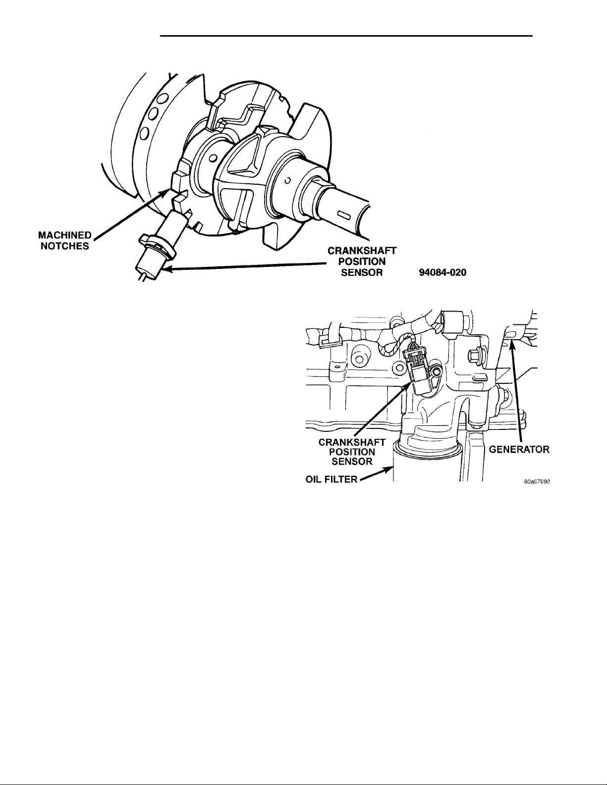
position sensor input. The second crankshaft counterweight has two sets of four timing reference notches
including a 60 degree signature notch (Fig. 7). From
the crankshaft position sensor input the PCM determines engine speed and crankshaft angle (position).
The notches generate pulses from high to low in
the crankshaft position sensor output voltage. When
a metal portion of the counterweight aligns with the
crankshaft position sensor, the sensor output voltage
goes low (less than 0.5 volts). When a notch aligns
with the sensor, voltage goes high (5.0 volts). As a
group of notches pass under the sensor, the output
Page 28
MACHINED NOTCHES CRANKSHAFT POSITIONSENSOR
CRANKSHAFT POSITIONSENSOROIL FILTERGENERATOR
14 - 28 FUEL SYSTEM PL
DESCRIPTION AND OPERATION (Continued)
Fig. 7 Timing Reference Notches
voltage switches from low (metal) to high (notch)
then back to low.
If available, an oscilloscope can display the square
wave patterns of each voltage pulses. From the width
of the output voltage pulses, the PCM calculates
engine speed. The width of the pulses represent the
amount of time the output voltage stays high before
switching back to low. The period of time the sensor
output voltage stays high before switching back to
low is referred to as pulse width. The faster the
engine is operating, the smaller the pulse width on
the oscilloscope.
By counting the pulses and referencing the pulse
from the 60 degree signature notch, the PCM calculates crankshaft angle (position). In each group of
timing reference notches, the first notch represents
69 degrees before top dead center (BTDC). The second notch represents 49 degrees BTDC. The third
notch represents 29 degrees. The last notch in each
set represents 9 degrees before top dead center
(TDC).
The timing reference notches are machined at 20°
increments. From the voltage pulse width the PCM
tells the difference between the timing reference
notches and the 60 degree signature notch. The 60
degree signature notch produces a longer pulse width
than the smaller timing reference notches. If the
camshaft position sensor input switches from high to
low when the 60 degree signature notch passes under
the crankshaft position sensor, the PCM knows cylinder number one is the next cylinder at TDC.
The crankshaft position sensor mounts to the
engine block behind the alternator, just above the oil
filter (Fig. 8).
Fig. 8 Crankshaft Position Sensor
ENGINE COOLANT TEMPERATURE SENSOR—PCM INPUT
The combination coolant temperature sensor has
two elements. One element supplies coolant temperature signal to the PCM. The other element supplies
coolant temperature signal to the instrument panel
gauge cluster. The PCM determines engine coolant
temperature from the coolant temperature sensor.
As coolant temperature varies the coolant temperature sensors resistance changes resulting in a different input voltage to the PCM and the instrument
panel gauge cluster.
When the engine is cold, the PCM will provide
slightly richer air- fuel mixtures and higher idle
speeds until normal operating temperatures are
reached.
Page 29
ENGINE COOLANTTEMPERATURESENSORCAMSHAFTPOSITIONSENSOR
FUEL RAIL
COOLANT TEMPER-ATURE SENSOR
PL FUEL SYSTEM 14 - 29
DESCRIPTION AND OPERATION (Continued)
SOHC
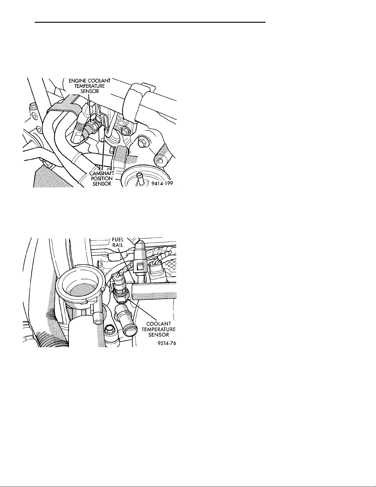
The coolant sensor threads into the rear of the cyl-
inder head, next to the camshaft position sensor (Fig.
9). New sensors have sealant applied to the threads.
Fig. 9 Engine Coolant Temperature Sensor—SOHC
DOHC
The coolant sensor threads into the intake manifold next to the thermostat housing (Fig. 10). New
sensors have sealant applied to the threads.
Fig. 10 Engine Coolant Temperature Sensor—DOHC
FUEL LEVEL SENSOR—PCM INPUT
The fuel level sensor (fuel gauge sending unit)
sends a signal to the PCM to indicate fuel level. The
purpose of this feature is to prevent a false setting of
misfire and fuel system monitor trouble codes if the
fuel level is less than approximately 15 percent of its
rated capacity. It is also used to send a signal for fuel
gauge operation via the CCD bus circuits.
HEATED OXYGEN SENSOR (O2S SENSOR)—PCM INPUT
As vehicles accumulate mileage, the catalytic convertor deteriorates. The deterioration results in a
less efficient catalyst. To monitor catalytic convertor
deterioration, the fuel injection system uses two
heated oxygen sensors. One sensor upstream of the
catalytic convertor, one downstream of the convertor.
The PCM compares the reading from the sensors to
calculate the catalytic convertor oxygen storage
capacity and converter efficiency. Also, the PCM uses
the upstream heated oxygen sensor input when
adjusting injector pulse width.
When the catalytic converter efficiency drops below
emission standards, the PCM stores a diagnostic
trouble code and illuminates the malfunction indicator lamp (MIL).
The O2S sensors produce voltages from 0 to 1 volt,
depending upon the oxygen content of the exhaust
gas in the exhaust manifold. When a large amount of
oxygen is present (caused by a lean air/fuel mixture),
the sensors produces a low voltage. When there is a
lesser amount present (rich air/fuel mixture) it produces a higher voltage. By monitoring the oxygen
content and converting it to electrical voltage, the
sensors act as a rich- lean switch.
The oxygen sensors are equipped with a heating
element that keeps the sensors at proper operating
temperature during all operating modes. Maintaining
correct sensor temperature at all times allows the
system to enter into closed loop operation sooner.
Also, it allows the system to remain in closed loop
operation during periods of extended idle.
In Closed Loop operation the PCM monitors the
O2S sensor input (along with other inputs) and
adjusts the injector pulse width accordingly. During
Open Loop operation the PCM ignores the O2 sensor
input. The PCM adjusts injector pulse width based
on preprogrammed (fixed) values and inputs from
other sensors.
The Automatic Shutdown (ASD) relay supplies battery voltage to both the upstream and downstream
heated oxygen sensors. The oxygen sensors are
equipped with a heating element. The heating elements reduce the time required for the sensors to
reach operating temperature.
UPSTREAM OXYGEN SENSOR
The input from the upstream heated oxygen sensor
tells the PCM the oxygen content of the exhaust gas.
Based on this input, the PCM fine tunes the air-fuel
ratio by adjusting injector pulse width.
The sensor input switches from 0 to 1 volt, depending
upon the oxygen content of the exhaust gas in the
exhaust manifold. When a large amount of oxygen is
present (caused by a lean air-fuel mixture), the sensor
produces voltage as low as 0.1 volt. When there is a
lesser amount of oxygen present (rich air-fuel mixture)
the sensor produces a voltage as high as 1.0 volt. By
monitoring the oxygen content and converting it to electrical voltage, the sensor acts as a rich-lean switch.
Page 30
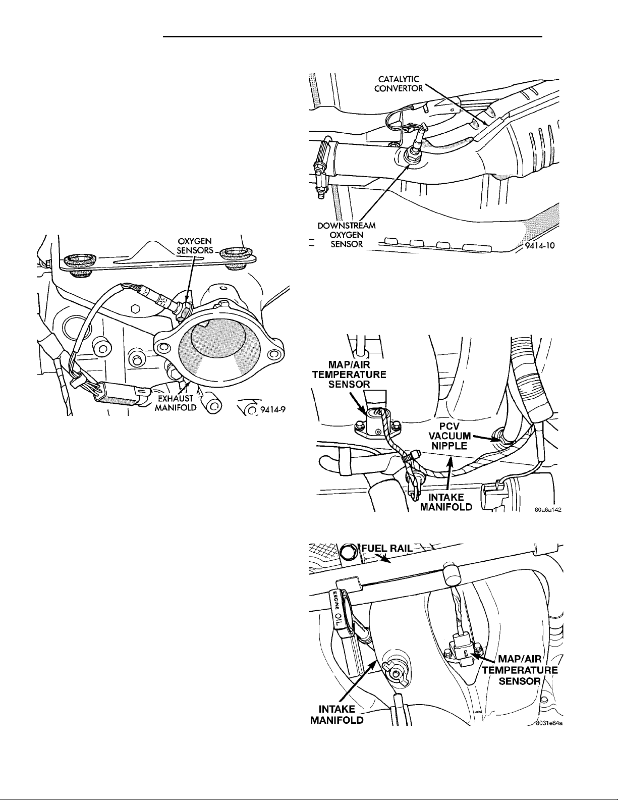
OXYGEN SEN-SORSEXHAUSTMANIFOLD
CATALYTIC CON-VERTORDOWNSTREAM OXYGENSENSOR
14 - 30 FUEL SYSTEM PL
DESCRIPTION AND OPERATION (Continued)
The heating element in the sensor provides heat to
the sensor ceramic element. Heating the sensor
allows the system to enter into closed loop operation
sooner. Also, it allows the system to remain in closed
loop operation during periods of extended idle.
In Closed Loop, the PCM adjusts injector pulse
width based on the upstream heated oxygen sensor
input along with other inputs. In Open Loop, the
PCM adjusts injector pulse width based on preprogrammed (fixed) values and inputs from other sensors.
The upstream oxygen sensor threads into the outlet flange of the exhaust manifold (Fig. 11).
Fig. 12 Downstream Heated Oxygen Sensor
The IAT sensor and Manifold Absolute Pressure
(MAP) switch are a combined into a single sensor
that attachs to the intake manifold (Fig. 13) or (Fig.
14).
Fig. 11 Upstream Heated Oxygen Sensor
DOWNSTREAM OXYGEN SENSOR
The downstream heated oxygen sensor threads into
the outlet pipe at the rear of the catalytic convertor
(Fig. 12). The downstream heated oxygen sensor
input is used to detect catalytic convertor deterioration. As the convertor deteriorates, the input from
the downstream sensor begins to match the upstream
sensor input except for a slight time delay. By comparing the downstream heated oxygen sensor input
to the input from the upstream sensor, the PCM calculates catalytic convertor efficiency.
IGNITION CIRCUIT SENSE—PCM INPUT
The ignition circuit sense input tells the Powertrain Control Module (PCM) the ignition switch has
energized the ignition circuit. Refer to the wiring diagrams for circuit information.
INTAKE AIR TEMPERATURE SENSOR—PCM INPUT
The Intake Air Temperature (IAT) sensor measures
the temperature of the intake air as it enters the
engine. The sensor supplies one of the inputs the
PCM uses to determine injector pulse width and
spark advance.
As Intake Air temperature varies the Intake Air
Temperature sensors resistance changes resulting in
a different input voltage to the PCM.
INTAKE MANI-FOLD MAP/AIR TEM-PERATURESENSOR
FUEL RAIL
Fig. 13 / MAP/Intake Air Temperature Sensor—SOHC
Fig. 14 MAP/Intake Air Temperature Sensor—DOHC
Page 31
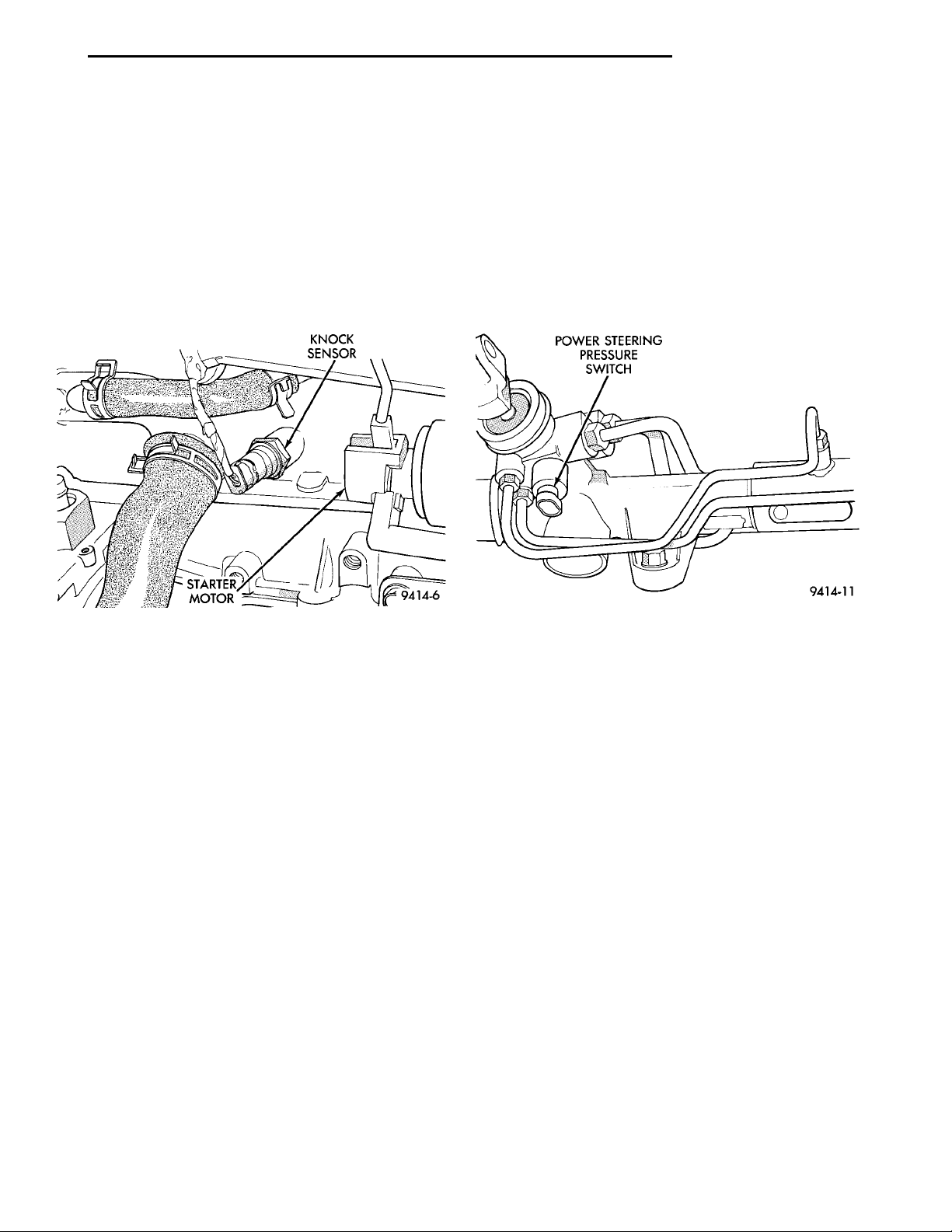
KNOCK SEN-SORSTARTERMOTOR
PL FUEL SYSTEM 14 - 31
DESCRIPTION AND OPERATION (Continued)
KNOCK SENSOR—PCM INPUT
The knock sensor threads into the side of the cylinder block in front of the starter (Fig. 15). When the
knock sensor detects a knock in one of the cylinders,
it sends an input signal to the PCM. In response, the
PCM retards ignition timing for all cylinders by a
scheduled amount.
Knock sensors contain a piezoelectric material
which sends an input voltage (signal) to the PCM. As
the intensity of the engine knock vibration increases,
the knock sensor output voltage also increases.
POWER STEERING PRESSURE SWITCH—PCM
INPUT
A pressure sensing switch is located on the power
steering gear. The switch (Fig. 16) provides an input
to the PCM during periods of high pump load and
low engine RPM; such as during parking maneuvers.
When power steering pump pressure exceeds 2758
kPa (400 psi), the switch is open. The PCM increases
idle air flow through the IAC motor to prevent
engine stalling. When pump pressure is low, the
switch is closed.
POWER STEERINGPRESSURE SWITCH
Fig. 15 Knock Sensor
MANIFOLD ABSOLUTE PRESSURE (MAP)
SENSOR—PCM INPUT
The PCM supplies 5 volts direct current to the
MAP sensor. The MAP sensor converts intake manifold pressure into voltage. The PCM monitors the
MAP sensor output voltage. As vacuum increases,
MAP sensor voltage decreases proportionately. Also,
as vacuum decreases, MAP sensor voltage increases
proportionately.
At key on, before the engine is started, the PCM
determines atmospheric air pressure from the MAP
sensor voltage. While the engine operates, the PCM
determines intake manifold pressure from the MAP
sensor voltage. Based on MAP sensor voltage and
inputs from other sensors, the PCM adjusts spark
advance and the air/fuel mixture.
The MAP/Intake Air Temperature sensor mounts to
the intake manifold (Fig. 13) and (Fig. 14).
Fig. 16 Power Steering Pressure Switch
SENSOR RETURN—PCM INPUT
The sensor return circuit provides a low electrical
noise ground reference for all of the systems sensors.
The sensor return circuit connects to internal ground
circuits within the powertrain control module.
SPEED CONTROL—PCM INPUT
The speed control system provides five separate
voltages (inputs) to the Powertrain Control Module
(PCM). The voltages correspond to the ON/OFF, SET,
RESUME and CANCEL.
The speed control ON voltage informs the PCM
that the speed control system has been activated.
The speed control SET voltage informs the PCM that
a fixed vehicle speed has been selected. The speed
control RESUME voltage indicates the previous fixed
speed is requested. The speed control CANCEL voltage tells the PCM to deactivate but retain set speed
in memory (same as depressing the brake pedal). The
speed control OFF voltage tells the PCM that the
speed control system has deactivated. Refer to Group
8H for more speed control information.
Page 32
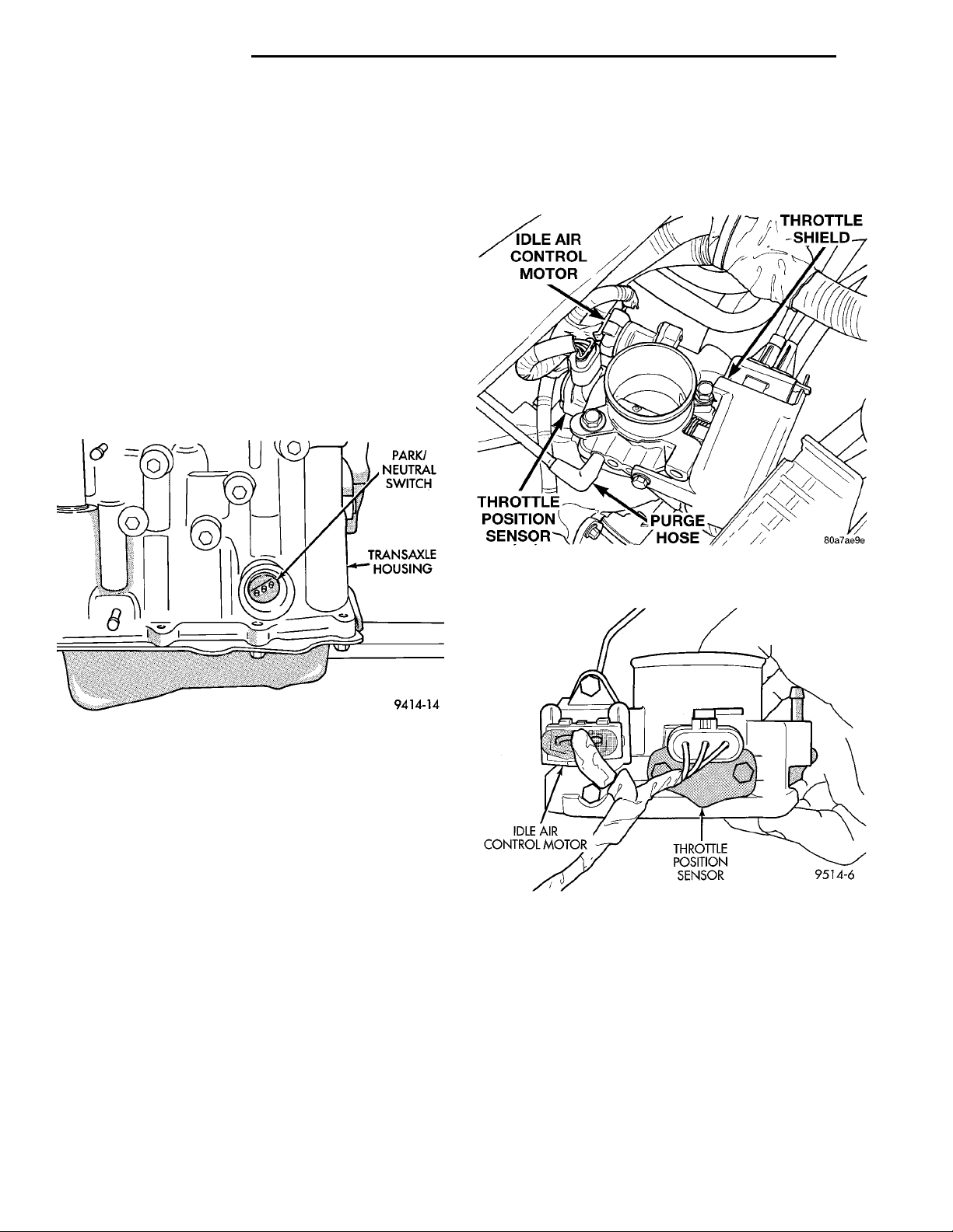
PARK/NEUTRALSWITCHTRANSAXLEHOUSING
14 - 32 FUEL SYSTEM PL
DESCRIPTION AND OPERATION (Continued)
THROTTLE SHIELDPURGE HOSETHROTTLE POSITION SEN-SORIDLE CONTROL MOTOR
IDLE AIR CONTROLMOTOR THROTTLEPOSITION SEN-SOR
SCI RECEIVE—PCM INPUT
SCI Receive is the serial data communication
receive circuit for the DRB scan tool. The Powertrain
Control Module (PCM) receives data from the DRB
through the SCI Receive circuit.
Along with inputs from other sensors, the PCM
uses the TPS input to determine current engine operating conditions. The PCM also adjusts fuel injector
pulse width and ignition timing based on these
inputs.
PARK/NEUTRAL POSITION SWITCH—PCM INPUT
The park/neutral position switch is located on the
automatic transaxle housing (Fig. 17). Manual transaxles do not use park/neutral switches. The switch
provides an input to the PCM to indicate whether
the automatic transaxle is in Park/Neutral, or a drive
gear selection. This input is used to determine idle
speed (varying with gear selection) and ignition timing advance. The park/neutral input is also used to
cancel vehicle speed control. The park/neutral switch
is sometimes referred to as the neutral safety switch.
Fig. 17 Park/Neutral Switch
THROTTLE POSITION SENSOR—PCM INPUT
The throttle position sensor mounts to the side of
the throttle body (Fig. 18) and (Fig. 19).
The Throttle Position Sensor (TPS) connects to the
throttle blade shaft. The TPS is a variable resistor
that provides the PCM with an input signal (voltage).
The signal represents throttle blade position. As the
position of the throttle blade changes, the resistance
of the TPS changes.
The PCM supplies approximately 5 volts DC to the
TPS. The TPS output voltage (input signal to the
powertrain control module) represents throttle blade
position. The TPS output voltage to the PCM varies
from approximately 0.35 to 1.03 volts at minimum
throttle opening (idle) to a maximum of 3.1 to 4.0
volts at wide open throttle.
Fig. 18 Throttle Position Sensor and Idle Air Control
Motor—SOHC
Fig. 19 Throttle Position Sensor and Idle Air Control
Motor—DOHC
Page 33
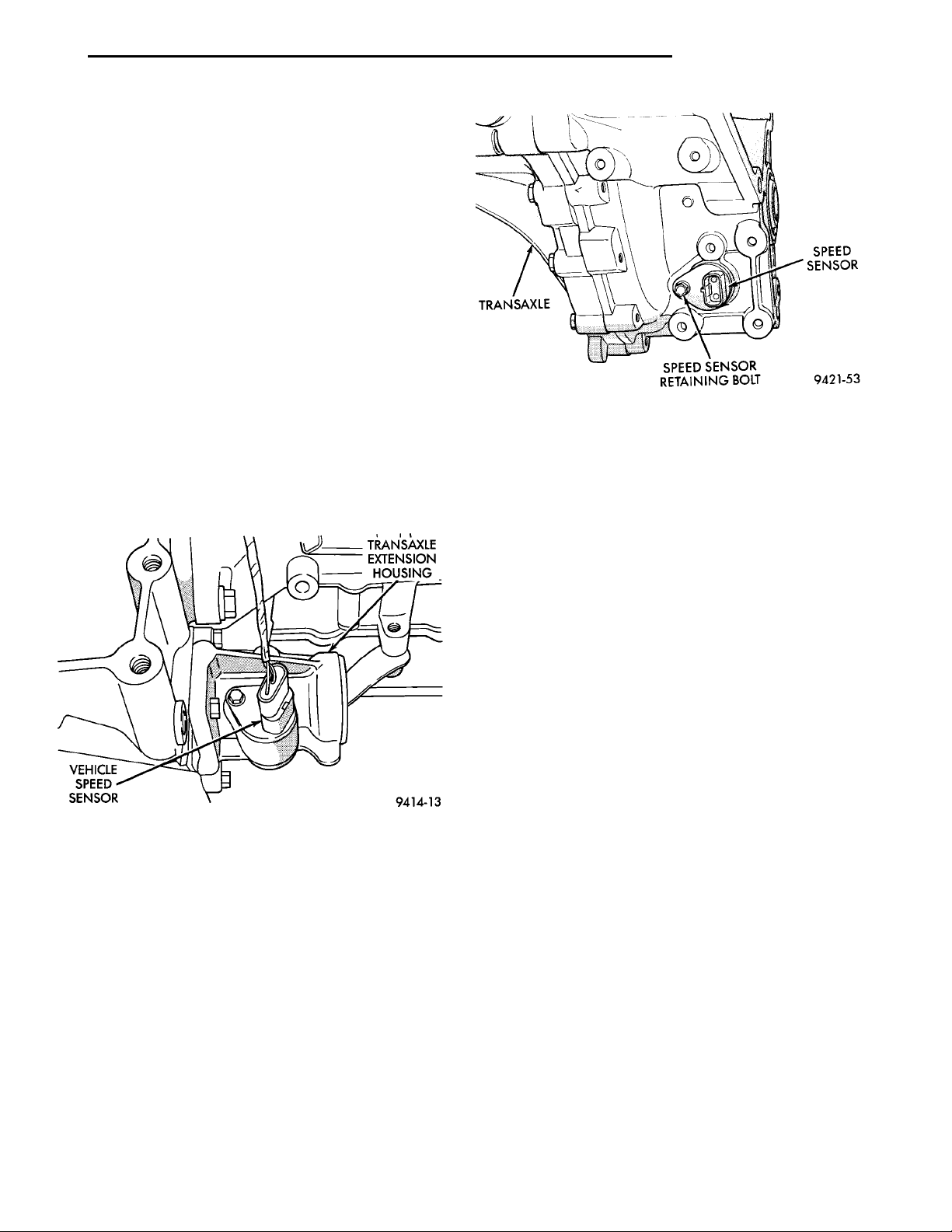
VEHICLESPEEDSENSOR
TRANSAXLE
EXTENSION
HOUSING
TRANSAXLE SPEEDSENSORSPEED SENSOR RETAININGBOLT
PL FUEL SYSTEM 14 - 33
DESCRIPTION AND OPERATION (Continued)
VEHICLE SPEED SENSOR—PCM INPUT
The vehicle speed sensor is located in the transmission extension housing (Fig. 20) and (Fig. 21). The
sensor input is used by the PCM to determine vehicle
speed and distance traveled.
The vehicle speed sensor generates 8 pulses per sensor revolution. These signals, in conjunction with a
closed throttle signal from the throttle position sensor,
indicate a closed throttle deceleration to the PCM.
Under deceleration conditions, the PCM adjusts the Idle
Air Control (IAC) motor to maintain a desired MAP
value.
When the vehicle is stopped at idle, a closed throttle signal is received by the PCM (but a speed sensor
signal is not received). Under idle conditions, the
PCM adjusts the IAC motor to maintain a desired
engine speed.
The vehicle speed sensor signal is also used to
operate the following functions or systems:
• Speedometer
• Speed control
Daytime Running Lights (Canadian Vehicles only).
•
PDC. The inside top of the PDC cover has a label
showing relay and fuse location.
Fig. 21 Vehicle Speed Sensor—Manual
Transmission
The air conditioning clutch relay is located in the
AUTOMATIC SHUTDOWN RELAY—PCM OUTPUT
The automatic shutdown (ASD) relay supplies battery voltage to the fuel injectors, electronic ignition
coil and the heating elements in the oxygen sensors.
A buss bar in the power distribution center (PDC)
supplies voltage to the solenoid side and contact side
of the relay. The ASD relay power circuit contains a
20 amp fuse between the buss bar in the PDC and
the relay. The fuse also protects the power circuit for
the fuel pump relay and pump. The fuse is located in
the PDC. Refer to Group 8W, Wiring Diagrams for
circuit information.
The PCM controls the relay by switching the
ground path for the solenoid side of the relay on and
off. The PCM turns the ground path off when the
ignition switch is in the Off position unless the 02
Fig. 20 Vehicle Speed Sensor—Automatic
Transmission
AIR CONDITIONING CLUTCH RELAY—PCM OUTPUT
The PCM controls the air conditioning clutch relay
ground circuit. Buss bars in the Power Distribution
Center (PDC) supply voltage to the solenoid side and
power side of the relay. When the PCM receives an
air conditioning input, it grounds the A/C compressor
clutch relay and the radiator fan relay.
When the PCM senses low idle speeds or wide open
throttle through the throttle position sensor, it removes
the ground for the A/C compressor clutch relay. When
the relay de-energizes, the contacts open preventing air
conditioning clutch engagement. Also, if the PCM senses
a part throttle launch condition, it disables the A/C compressor clutch for several seconds.
Heater Monitor test is being run. Refer to Group 25,
On-Board Diagnostics. When the ignition switch is in
the On or Crank position, the PCM monitors the
crankshaft position sensor and camshaft position sensor signals to determine engine speed and ignition
timing (coil dwell). If the PCM does not receive the
crankshaft position sensor and camshaft position sensor signals when the ignition switch is in the Run
position, it will de- energize the ASD relay.
The ASD relay is located in the PDC. The inside
top of the PDC cover has a label showing relay and
fuse location.
CHARGING SYSTEM INDICATOR LAMP—PCM OUTPUT
The PCM turns the instrument panel Charging
System Lamp on. Refer to Group 8C for charging system information.
Page 34
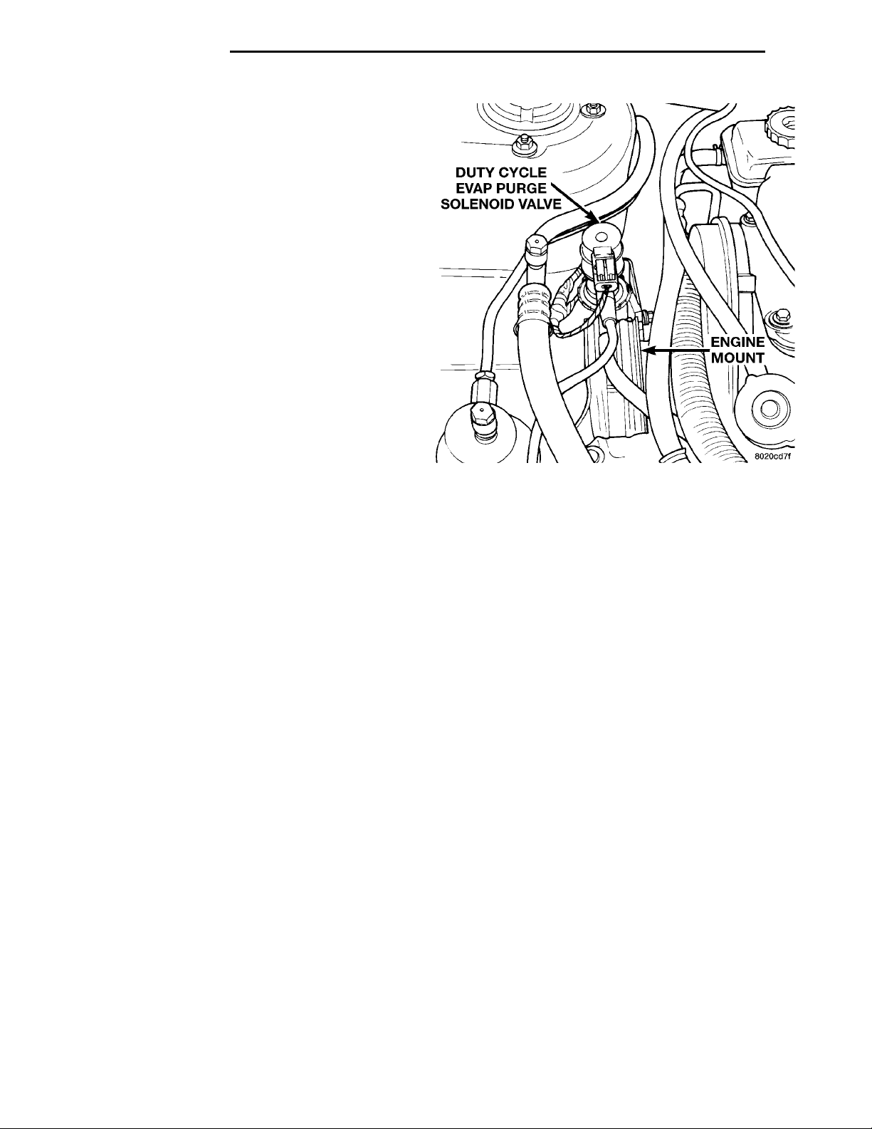
DUTY CYCLE EVAPPURGE SOLENOIDVALVE ENGINEMOUNT
14 - 34 FUEL SYSTEM PL
DESCRIPTION AND OPERATION (Continued)
FUEL PUMP RELAY—PCM OUTPUT
The fuel pump relay supplies battery voltage to the
fuel pump. A buss bar in the Power Distribution Center (PDC) supplies voltage to the solenoid side and
contact side of the relay. The fuel pump relay power
circuit contains a 20 amp fuse between the buss bar
in the PDC and the relay. The fuse also protects the
power circuit for the Automatic Shutdown (ASD)
relay. The fuse is located in the PDC. Refer to Group
8W, Wiring Diagrams for circuit information.
The PCM controls the fuel pump relay by switching the ground path for the solenoid side of the relay
on and off. The PCM turns the ground path off when
the ignition switch is in the Off position. When the
ignition switch is in the On position, the PCM energizes the fuel pump. If the crankshaft position sensor
does not detect engine rotation, the PCM de- energizes the relay after approximately one second.
The fuel pump relay is located in the PDC. The
inside top of the PDC cover has a label showing relay
and fuse location.
DUTY CYCLE EVAP PURGE SOLENOID—PCM OUTPUT
The duty cycle EVAP purge solenoid regulates the
rate of vapor flow from the EVAP canister to the
throttle body. The powertrain control module operates the solenoid.
During the cold start warm-up period and the hot
start time delay, the PCM does not energize the solenoid. When de-energized, no vapors are purged.
The engine enters closed loop operation after it
reaches a specified temperature and the programmed
time delay ends. During closed loop operation, the
PCM energizes and de-energizes the solenoid 5 to 10
times per second, depending upon operating conditions. The PCM varies the vapor flow rate by changing solenoid pulse width. Pulse width is the amount
of time the solenoid is energized.
The solenoid attaches to a bracket near the front
engine mount (Fig. 22). To operate correctly, the solenoid must be installed with the electrical connector
on top.
ELECTRIC EGR TRANSDUCER—PCM OUTPUT
The Electric EGR Transducer contains an electrically operated solenoid and a back-pressure controlled vacuum transducer (Fig. 23). The PCM
operates the solenoid based on inputs from the multiport fuel injection system. The transducer and EGR
valve are serviced as an assembly.
When the PCM energizes the solenoid, vacuum
does not reach the transducer. Vacuum flows to the
transducer when the PCM de-energizes the solenoid.
When exhaust system back-pressure becomes high
enough, it fully closes a bleed valve in the vacuum
Fig. 22 Duty Cycle EVAP Purge Solenoid
transducer. When the PCM de-energizes the solenoid
and back-pressure closes the transducer bleed valve,
vacuum flows through the transducer to operate the
EGR valve.
De-energizing the solenoid, but not fully closing the
transducer bleed hole (because of low back-pressure),
varies the strength of the vacuum signal applied to
the EGR valve. Varying the strength of the vacuum
signal changes the amount of EGR supplied to the
engine. This provides the correct amount of exhaust
gas recirculation for different operating conditions.
The transducer and EGR valve mount to the rear
of the cylinder head (Fig. 23).
GENERATOR FIELD—PCM OUTPUT
The PCM regulates the charging system voltage
within a range of 12.9 to 15.0 volts. Refer to Group
8A for Battery system information and 8C for charging system information.
IDLE AIR CONTROL MOTOR—PCM OUTPUT
The Idle Air Control (IAC) motor is mounted on the
throttle body. The PCM operates the idle air control
motor (Fig. 24). The PCM adjusts engine idle speed
through the idle air control motor to compensate for
engine load, coolant temperature or barometric pressure changes.
The throttle body has an air bypass passage that
provides air for the engine during closed throttle idle.
The idle air control motor pintle protrudes into the
air bypass passage and regulates air flow through it.
The PCM adjusts engine idle speed by moving the
IAC motor pintle in and out of the bypass passage.
Page 35
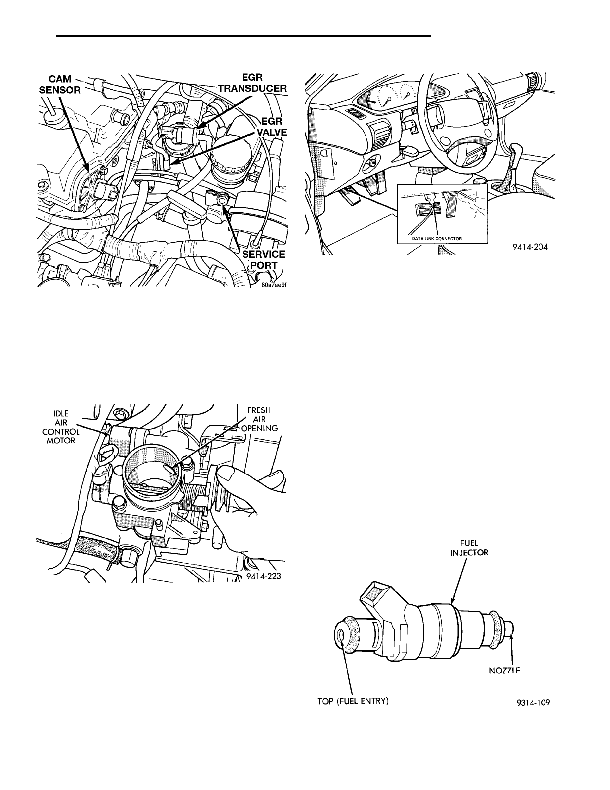
EGR TRANSDUCEREGR VALVESERVICE PORTCAM SENSOR
IDLE AIRCONTROLMOTOR FRESH AIROPENING
DATA LINK CONNECTOR
PL FUEL SYSTEM 14 - 35
DESCRIPTION AND OPERATION (Continued)
Fig. 25 Data Link Connector
FUEL INJECTORS—PCM OUTPUT
Fig. 23 Electric EGR Backpressure Transducer—
Typical
The adjustments are based on inputs the PCM
receives. The inputs are from the throttle position
sensor, crankshaft position sensor, coolant temperature sensor, MAP sensor, vehicle speed sensor and
various switch operations (brake, park/neutral, air
conditioning).
The 2.0L engine uses electrically operated top feed
fuel injectors (Fig. 26). The Automatic Shutdown
(ASD) relay supplies battery voltage to the fuel injectors. The PCM controls the ground path for each
injector in sequence. By switching the ground paths
on and off, the PCM fine-tunes injector pulse width.
Injector pulse width refers to the amount of time an
injector operates.
The PCM determines injector synchronization from
the camshaft position sensor and crankshaft position
sensor inputs. The PCM grounds the ASD and fuel
pump relays after receiving the camshaft position
sensor and crankshaft position sensor inputs.
The PCM energizes the injectors in a sequential
order during all engine operating conditions except
FUEL INJECTORTOP (FUEL ENTRY) NOZZLE
start-up. For the first injector pulse width during
start-up, all injectors are energized at the same time.
Once the PCM determines crankshaft position, it
begins energizing the injectors in sequence.
Fig. 24 Idle Air Control Motor Air Bypass Passage—
Typical
DATA LINK CONNECTOR
The data link connector (diagnostic connector)
links the DRB scan tool with the powertrain control
module (PCM). Refer to On-Board Diagnostics in the
General Diagnosis section of this group. The data
link connector is located inside the vehicle, under the
instrument panel, left of the steering column (Fig.
25).
Fig. 26 Fuel Injector
Page 36
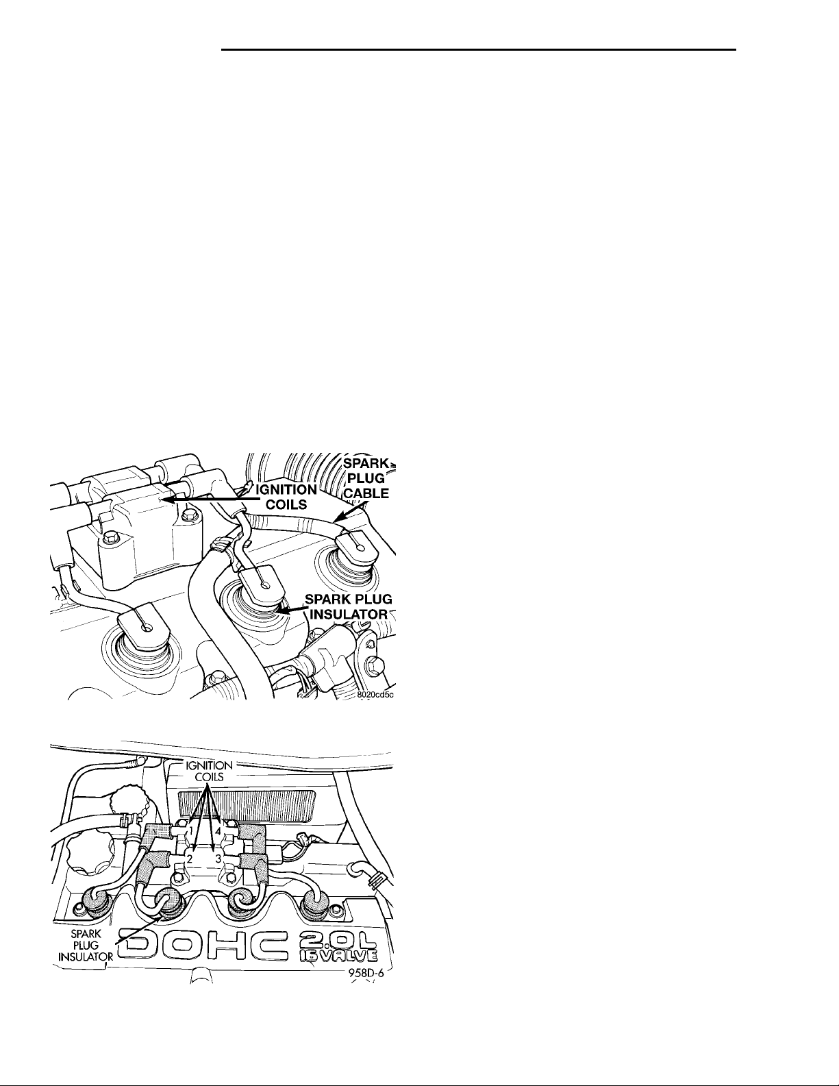
14 - 36 FUEL SYSTEM PL
DESCRIPTION AND OPERATION (Continued)
IGNITION COIL—PCM OUTPUT
The coil assembly consists of 2 coils molded
together. The coil assembly is mounted over the valve
cover (Fig. 27) or (Fig. 28). High tension leads route
to each cylinder from the coil. The coil fires two
spark plugs every power stroke. One plug is the cylinder under compression, the other cylinder fires on
the exhaust stroke. Coil number one fires cylinders 1
and 4. Coil number two fires cylinders 2 and 3. The
PCM determines which of the coils to charge and fire
at the correct time.
The Auto Shutdown (ASD) relay provides battery
voltage to the ignition coil. The PCM provides a
ground contact (circuit) for energizing the coil. When
the PCM breaks the contact, the energy in the coil
primary transfers to the secondary causing the
spark. The PCM will de-energize the ASD relay if it
does not receive the crankshaft position sensor and
camshaft position sensor inputs. Refer to Auto Shutdown (ASD) Relay—PCM Output in this section for
relay operation.
MALFUNCTION INDICATOR (CHECK ENGINE)
LAMP—PCM OUTPUT
The PCM supplies the malfunction indicator (check
engine) lamp on/off signal to the instrument panel
through the CCD Bus. The CCD Bus is a communications port. Various modules use the CCD Bus to
exchange information.
The Check Engine lamp comes on each time the
ignition key is turned ON and stays on for 3 seconds
as a bulb test.
The Malfunction Indicator Lamp (MIL) stays on
continuously, when the PCM has entered a Limp-In
mode or identified a failed emission component. During Limp-in Mode, the PCM attempts to keep the
system operational. The MIL signals the need for
immediate service. In limp-in mode, the PCM compensates for the failure of certain components that
send incorrect signals. The PCM substitutes for the
incorrect signals with inputs from other sensors.
If the PCM detects active engine misfire severe
enough to cause catalyst damage, it flashes the MIL.
At the same time the PCM also sets a Diagnostic
Trouble Code (DTC).
For signals that can trigger the MIL (Check
Engine Lamp) refer to Group 25, On-Board
Dianostics.
The MIL can also display diagnostic trouble codes.
Cycle the ignition switch on, off, on, off, on, within 5
seconds and any diagnostic trouble codes stored in
the PCM will be displayed. Refer to On-Board Diagnostics in Group 25, Emission Control Systems Diagnostic Trouble Code Descriptions.
IGNITIONCOILSSPARK PLUGINSULATOR
Fig. 27 Ignition Coil Pack—SOHC
Fig. 28 Ignition Coil Pack—DOHC
RADIATOR FAN CONTROL MODULE—PCM OUTPUT
The radiator fan runs when coolant temperature
and A/C system pressure demand cooling. The radiator fan circuit contains a Pulse Width Module
(PWM). Refer to the Group 8W for a circuit schematic.
A 5 volt signal is supplied to the PWM. The PCM
provides a pulsed ground for the PWM. Depending
upon the amount of pulse on time, the PWM puts out
a proportional voltage to the fan motor at the lower
speed. For instance, if the on time is 30 percent, then
the voltage to the fan motor will be 3.6 volts.
When engine coolant reaches approximately 99°C
(210°F) the PCM grounds the PWM relay. When the
PCM grounds the relay it operates at a 30% duty
cycle and immediately ramps up to 100% duty cycle.
The PCM de-energizes the PWM relay when coolant
temperature drops to approximately 93°C (199°F).
Also, when the air conditioning pressure switch
closes, the PCM grounds the PWM. The air conditioning switch closes at 285 psi 610 psi. When air
Page 37
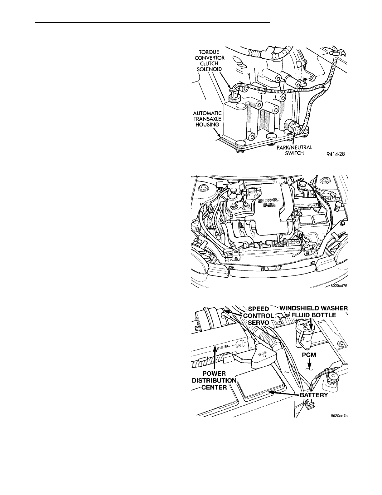
TORQUE CON-VERTORCLUTCH SOLE-NOIDAUTOMATICTRANSAXLEHOUSING PARK/NEUTRAL SWITCH
POWER DIS-TRIBUTIONCENTER SPEED CONTROLSERVOWINDSHIELDWASHER FLUIDBOTTLEPCMBATTERY
PL FUEL SYSTEM 14 - 37
DESCRIPTION AND OPERATION (Continued)
conditioning pressure drops approximately 40 psi, the
pressure switch opens and the fan turns off.
The PWM relay is located on the left front inner
frame just behind the radiator.
SPEED CONTROL—PCM INPUT
The speed control system provides five separate
voltages (inputs) to the Powertrain Control Module
(PCM). The voltages correspond to the ON/OFF, SET,
RESUME and CANCEL.
The speed control ON voltage informs the PCM
that the speed control system has been activated.
The speed control SET voltage informs the PCM that
a fixed vehicle speed has been selected. The speed
control RESUME voltage indicates the previous fixed
speed is requested. The speed control CANCEL voltage tells the PCM to deactivate but retain set speed
in memory (same as depressing the brake pedal). The
speed control OFF voltage tells the PCM that the
speed control system has deactivated. Refer to Group
8H for more speed control information.
Fig. 29 Torque Convertor Clutch Solenoid
SCI RECEIVE—PCM INPUT
SCI Receive is the serial data communication
receive circuit for the DRB scan tool. The Powertrain
Control Module (PCM) receives data from the DRB
through the SCI Receive circuit.
TACHOMETER—PCM OUTPUT
The PCM operates the tachometer on the instrument panel. The PCM calculates engine RPM from
the crankshaft position sensor input.
TORQUE CONVERTOR CLUTCH SOLENOID—PCM OUTPUT
Three-speed automatic transaxles use a torque converter clutch solenoid. The PCM controls the engagement of the torque converter clutch through the
solenoid (Fig. 29). The torque converter clutch is
engaged up only in direct drive mode. Refer to Group
21 for transmission information.
DIAGNOSIS AND TESTING
VISUAL INSPECTION—SOHC
Before diagnosing or servicing the fuel injection
system, perform a visual inspection for loose, disconnected, or misrouted wires and hoses (Fig. 30). A
thorough visual inspection that includes the following
checks saves unnecessary test and diagnostic time.
(1) Inspect the battery connections. Clean corroded
terminals (Fig. 31).
(2) Check the 2 PCM 40-way connector for
stretched wires on pushed out terminals (Fig. 31).
Fig. 30 2.0L SOHC Engine Compartment
Fig. 31 Battery, PCM, and PDC
Page 38
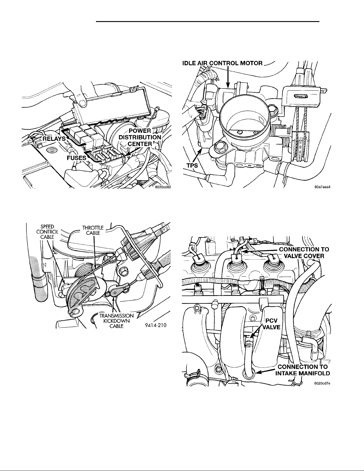
POWER DISTRI-BUTION CEN-TER FUSESRELAYS
SPEED CON-TROL CABLE THROTTLECABLETRANSMISSIONKICKDOWNCABLE
14 - 38 FUEL SYSTEM PL
IDLE AIR CONTROL MOTORTPS
DIAGNOSIS AND TESTING (Continued)
(3) Open the Power Distribution Center (PDC).
Check for blown fuses. Ensure the relays and fuses
are fully seated in the PDC (Fig. 32). A label on the
underside of the PDC cover shows the locations of
each relay and fuse.
(5) Check the electrical connections at the idle air
CONNECTION TO VALVECOVERPCV VALVECONNECTION TO INTAKEMANIFOLD
control motor and throttle position sensor (Fig. 34).
Fig. 32 Power Distribution Center
(4) Verify the throttle cable operates freely (Fig.
33).
Fig. 33 Throttle Cable—Automatic Transmission
Fig. 34 Idle Air Control Motor and Throttle Position
Sensor—Typical
(6) Check hose connections between the PCV
valve, vacuum port - intake manifold and the oil separator (Fig. 35).
Fig. 35 PCV Valve
Page 39
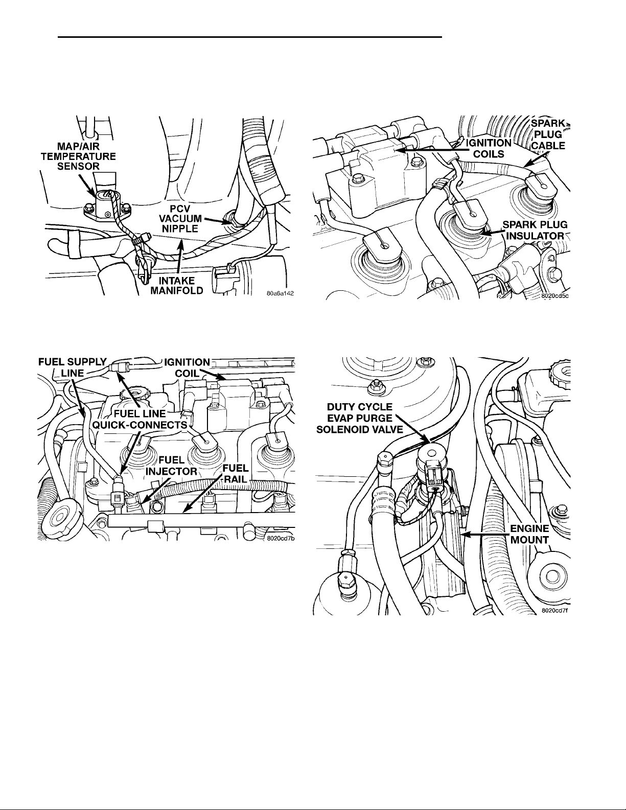
MAP/AIR TEMPERATURESENSORPCV VACUUM NIPPLEINTAKE MANIFOLD
FUEL SUP-
PLY LINE
FUEL LINEQUICK-CONNECTSIGNITION COILFUELRAIL
FUEL INJEC-
TOR
PL FUEL SYSTEM 14 - 39
DIAGNOSIS AND TESTING (Continued)
IGNITIONCOILSSPARK PLUG CABLESPARK PLUGINSULATOR
(7) Inspect the electrical connections at the MAP
sensor/intake air temperature sensor and the (Fig.
36).
Fig. 36 MAPIntake Air Temperature Sensor
(8) Inspect the fuel injector electrical connections
(Fig. 37).
(9) Inspect the ignition coil electrical connector.
DUTY CYCLE EVAPPURGE SOLENOIDVALVE ENGINEMOUNT
Ensure the spark plug insulators are firmly seated
over the spark plugs (Fig. 38).
Fig. 38 Ignition Coil and Spark Plugs—Typical
(10) Inspect the electrical and hose connections at
the duty cycle purge solenoid (Fig. 39).
Fig. 37 Fuel Injectors
Fig. 39 Duty Cycle Purge Solenoid
Page 40
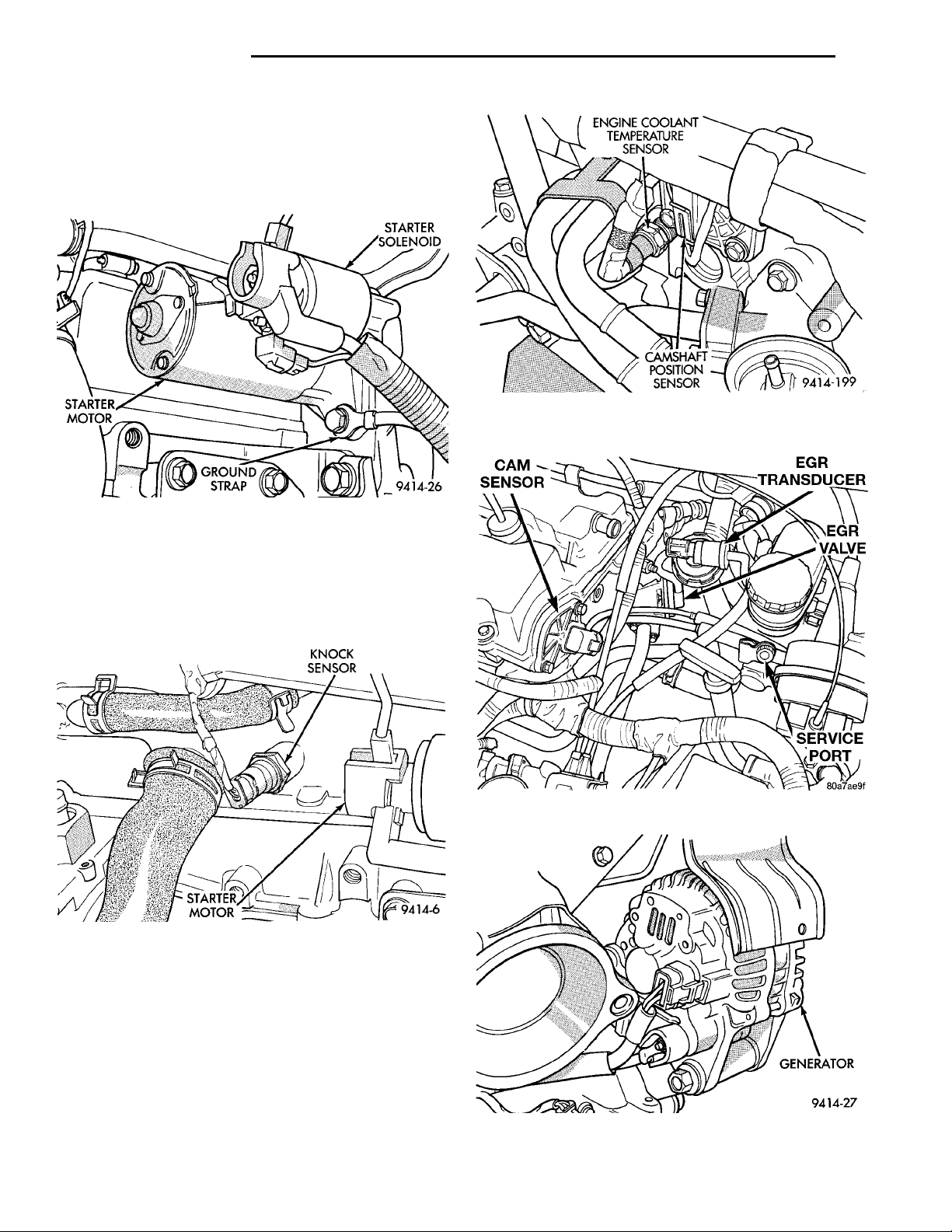
14 - 40 FUEL SYSTEM PL
DIAGNOSIS AND TESTING (Continued)
(11) Check the electrical connection to the radiator
STARTER
MOTOR
fan.
STARTER SOLENOIDGROUNDSTRAP
(12) Inspect for corrosion on the electrical connections at the starter motor solenoid. Check the ground
cable connection below the starter motor (Fig. 40).
Fig. 40 Starter Motor and Ground Strap
(13) Inspect the air cleaner filter element. Replace
KNOCK SEN-SORSTARTERMOTOR
as necessary. Check the air induction system for
restrictions.
(14) Check the electrical connection at the knock
sensor (Fig. 41).
Fig. 42 Camshaft Position Sensor and Engine
Coolant Temperature Sensor
Fig. 41 Knock Sensor
(15) Check the electrical connections at the camshaft position sensor and engine coolant temperature
sensor (Fig. 42).
(16) Check the electrical connector at the Electronic EGR Transducer. Inspect the vacuum and back
pressure hoses at the solenoid and transducer for
leaks (Fig. 43).
(17) Inspect the electrical connections at the generator (Fig. 44). Check the generator belt for glazing
or damage.
GENERATOR
Fig. 43 Electronic EGR Transducer
Fig. 44 Generator
Page 41
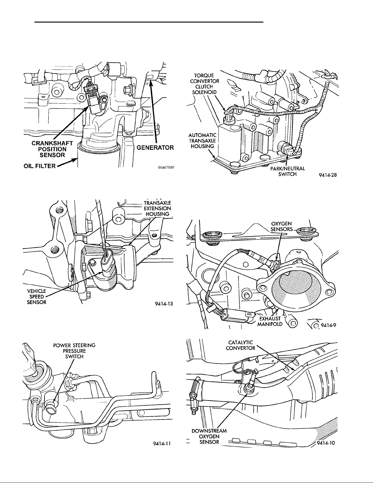
CRANKSHAFT POSITIONSENSOROIL FILTERGENERATOR
VEHICLESPEEDSENSOR
POWER STEERINGPRESSURE SWITCH
TRANSAXLE
EXTENSION
HOUSING
TORQUE CON-VERTORCLUTCH SOLE-NOIDAUTOMATICTRANSAXLEHOUSING PARK/NEUTRAL SWITCH
OXYGEN SEN-SORSEXHAUSTMANIFOLD
PL FUEL SYSTEM 14 - 41
DIAGNOSIS AND TESTING (Continued)
(18) Inspect the electrical connector at the crankshaft position sensor (Fig. 45).
Fig. 45 Crankshaft Position Sensor
(19) Check the electrical connection at the vehicle
speed sensor (Fig. 46).
(21) On vehicles with automatic transaxles, check
the electrical connections at the park/neutral switch
and the torque convertor clutch solenoid (Fig. 48).
Fig. 48 Park/Neutral Switch and Torque Convertor
Clutch Solenoid
(22) Inspect the electrical connections at the
upstream and downstream heated oxygen sensors
(Fig. 49) and (Fig. 50).
Fig. 46 Vehicle Speed Sensor
(20) Check the electrical connection at the power
steering pressure switch on the power steering gear
housing (Fig. 47).
Fig. 47 Power Steering Pressure Switch
CATALYTIC CON-VERTORDOWNSTREAM OXYGENSENSOR
Fig. 49 Upstream Heated Oxygen Sensor
Fig. 50 Downstream Heated Oxygen Sensor
Page 42
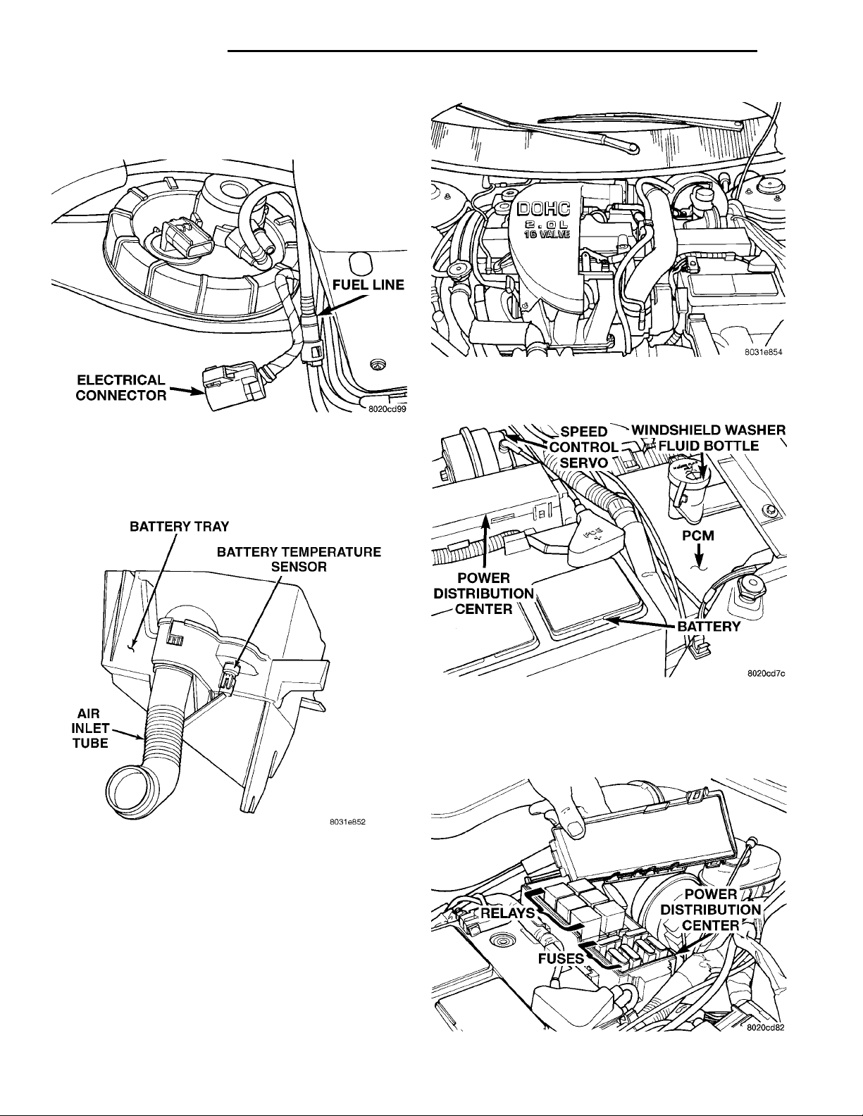
ELECTRICAL CON-
NECTOR
BATTERY TRAYBATTERY TEMPERATURESENSORAIR INLETTUBE
FUEL LINE
POWER DIS-TRIBUTIONCENTER SPEED CONTROLSERVOWINDSHIELDWASHER FLUIDBOTTLEPCMBATTERY
14 - 42 FUEL SYSTEM PL
DIAGNOSIS AND TESTING (Continued)
(23)
Inspect the fuel pump module electrical connection at the fuel tank for corrosion or damage (Fig. 51).
Check for pinched, kinked or damaged fuel supply tube.
Fig. 53 2.0L DOHC Engine Compartment
(2) Check the 2 PCM 40-way connector for
stretched wires on pushed out terminals (Fig. 54).
Fig. 51 Fuel Pump Module Electrical Connector
(24) Inspect the connections to the speed control
servo, if equipped (Fig. 31). Refer to Group 8H, Vehicle Speed Control.
Fig. 52 Battery Temp. Sensor Connectors
(25) Inspect the connection at the battery temperature sensor (Fig. 52).
VISUAL INSPECTION—DOHC
Before diagnosing or servicing the fuel injection
system, perform a visual inspection for loose, disconnected, or misrouted wires and hoses (Fig. 53). A
thorough visual inspection that includes the following
checks saves unnecessary test and diagnostic time.
(1) Inspect the battery connections. Clean corroded
terminals (Fig. 31).
Fig. 54 Battery, PCM, and PDC
POWER DISTRI-BUTION CEN-TER FUSESRELAYS
(3)
Open the Power Distribution Center (PDC). Check
for blown fuses. Ensure the relays and fuses are fully
seated in the PDC (Fig. 55). A label on the underside of
the PDC cover shows the locations of each relay and fuse.
Fig. 55 Power Distribution Center
Page 43
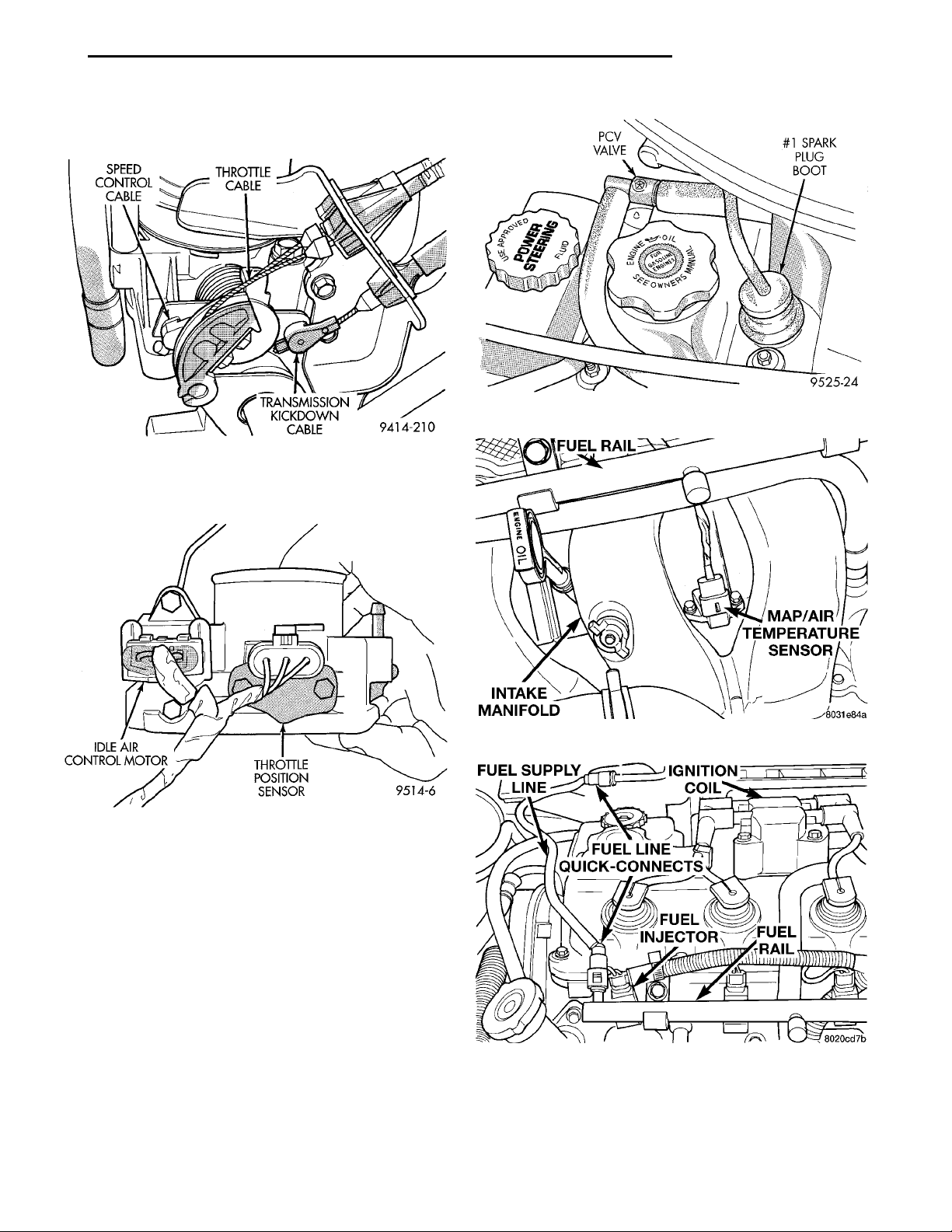
SPEED CON-TROL CABLE THROTTLECABLETRANSMISSIONKICKDOWNCABLE
IDLE AIR CONTROLMOTOR THROTTLEPOSITION SEN-SOR
INTAKE MANI-FOLD MAP/AIR TEM-PERATURESENSOR
FUEL SUP-
PLY LINE
PCV VALVE #1 SPARK PLUGBOOT
FUEL RAIL
FUEL LINEQUICK-CONNECTSIGNITION COILFUELRAIL
FUEL INJEC-
TOR
PL FUEL SYSTEM 14 - 43
DIAGNOSIS AND TESTING (Continued)
(4) Verify the throttle cable operates freely (Fig.
56).
Fig. 58 PCV Valve
Fig. 56 Throttle Cable—Automatic Transmission
(5) Check the electrical connections at the idle air
control motor and throttle position sensor (Fig. 57).
Fig. 57 Idle Air Control Motor and Throttle Position
Sensor—Typical
(6) Check hose connections between the PCV
valve, vacuum port - intake manifold and the oil separator (Fig. 58).
(7) Inspect the electrical connections at the MAP
sensor/intake air temperature sensor and the (Fig.
59).
(8) Inspect the fuel injector electrical connections
(Fig. 60).
Fig. 59 MAP/Intake Air Temperature Sensor
Fig. 60 Fuel Injectors—Typical
Page 44
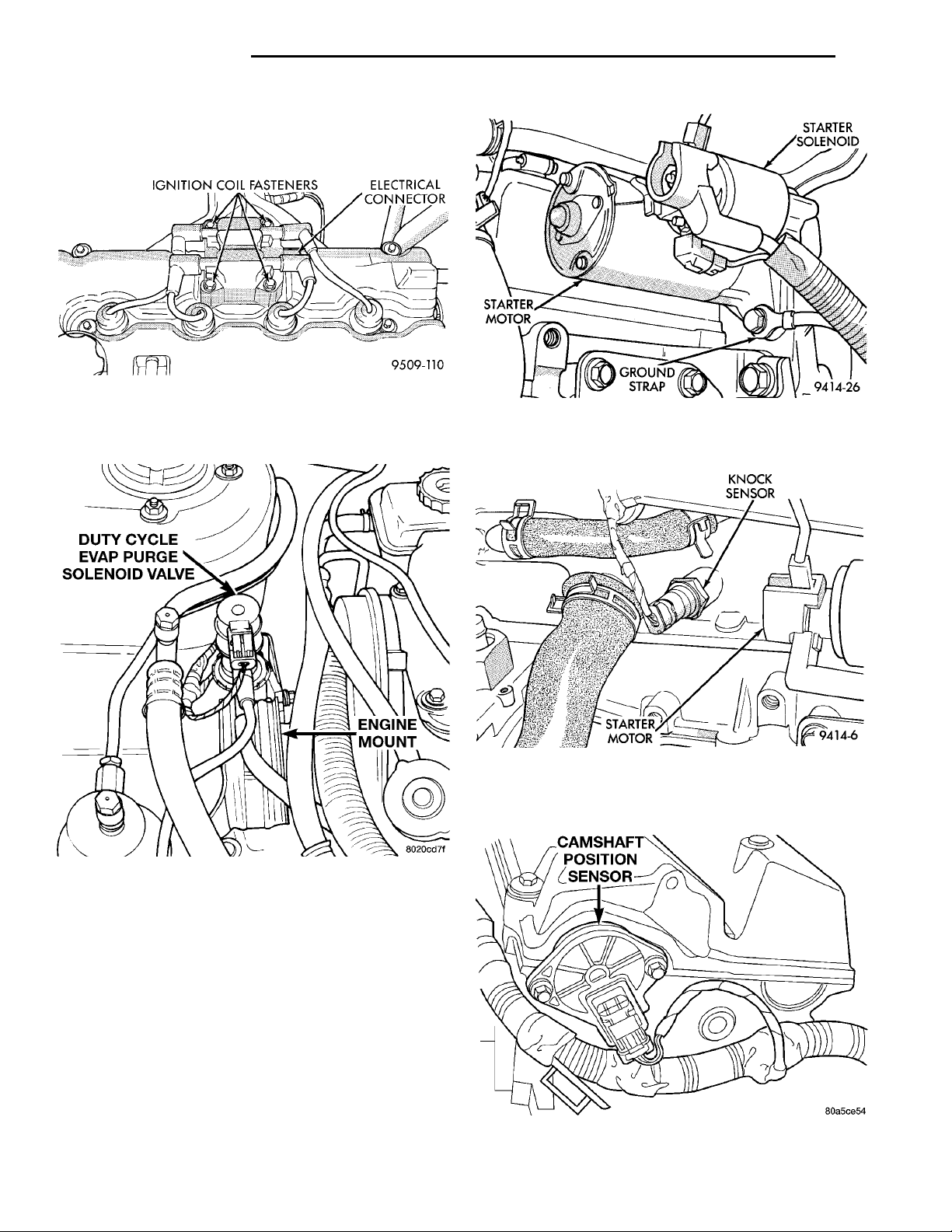
KNOCK SEN-SORSTARTERMOTOR
DUTY CYCLE EVAPPURGE SOLENOIDVALVE ENGINEMOUNT
IGNITION COIL FAS-
TENERS
ELECTRICALCONNECTOR
STARTER
MOTOR
STARTER SOLENOIDGROUNDSTRAP
14 - 44 FUEL SYSTEM PL
DIAGNOSIS AND TESTING (Continued)
(9) Inspect the ignition coil electrical connector.
Ensure the spark plug insulators are firmly seated
over the spark plugs (Fig. 61).
Fig. 61 Ignition Coil and Spark Plugs
(10) Inspect the electrical and hose connections at
the duty cycle purge solenoid (Fig. 62).
Fig. 63 Starter Motor and Ground Strap
(14) Check the electrical connection at the knock
sensor (Fig. 64).
CAMSHAFT POSITION SEN-SOR
Fig. 64 Knock Sensor
(15) Check the electrical connections at the camshaft position sensor (Fig. 65) and engine coolant
temperature sensor (Fig. 66).
Fig. 62 Duty Cycle Purge Solenoid
(11) Check the electrical connection to the radiator
fan.
(12) Inspect for corrosion on the electrical connections at the starter motor solenoid. Check the ground
cable connection below the starter motor (Fig. 63).
(13) Inspect the air cleaner filter element. Replace
as necessary. Check the air induction system for
restrictions.
Fig. 65 Camshaft Position Sensor
Page 45
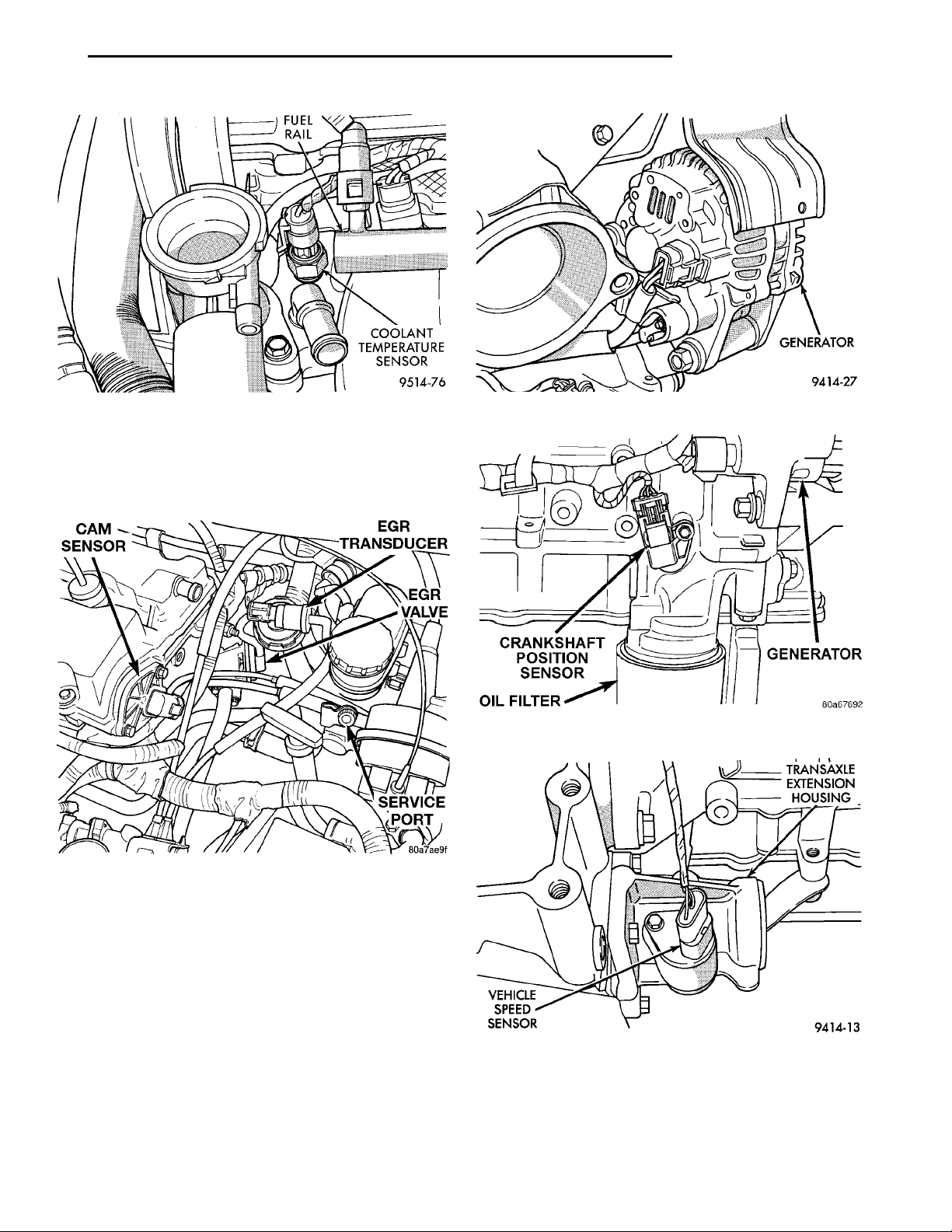
EGR TRANSDUCEREGR VALVESERVICE PORTCAM SENSOR
FUEL RAIL
COOLANT TEMPER-ATURE SENSOR
CRANKSHAFT POSITIONSENSOROIL FILTERGENERATOR
VEHICLESPEEDSENSOR
GENERATOR
TRANSAXLE
EXTENSION
HOUSING
PL FUEL SYSTEM 14 - 45
DIAGNOSIS AND TESTING (Continued)
Fig. 66 Engine Coolant Temperature Sensor
(16) Check the electrical connector at the Electronic EGR Transducer. Inspect the vacuum and back
pressure hoses at the solenoid and transducer for
leaks (Fig. 67).
Fig. 68 Generator
Fig. 69 Crankshaft Position Sensor
Fig. 67 Electronic EGR Transducer
(17) Inspect the electrical connections at the generator (Fig. 68). Check the generator belt for glazing
or damage.
(18) Inspect the electrical connector at the crankshaft position sensor (Fig. 69).
(19) Check the electrical connection at the vehicle
speed sensor (Fig. 70).
Fig. 70 Vehicle Speed Sensor
Page 46
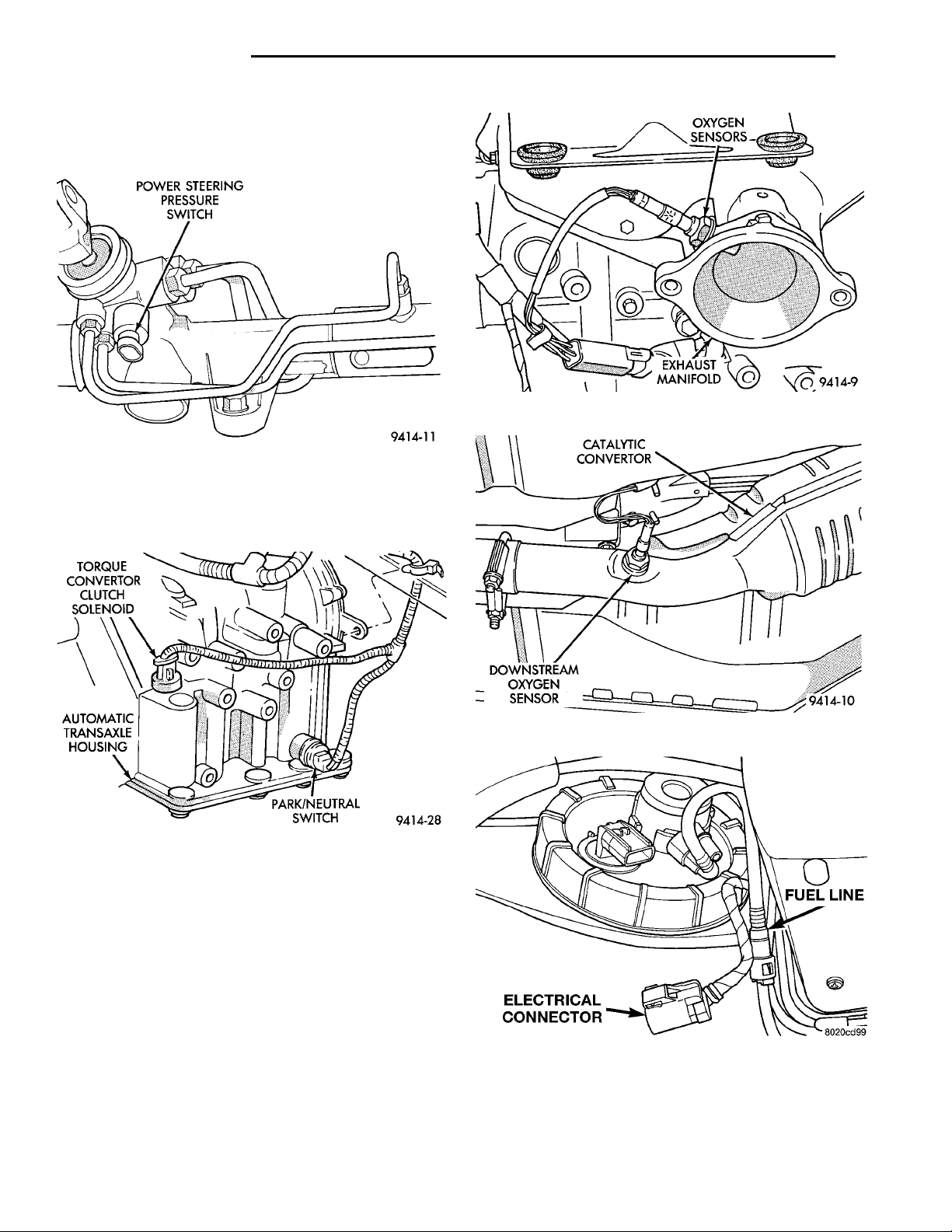
TORQUE CON-VERTORCLUTCH SOLE-NOIDAUTOMATICTRANSAXLEHOUSING PARK/NEUTRAL SWITCH
POWER STEERINGPRESSURE SWITCH
CATALYTIC CON-VERTORDOWNSTREAM OXYGENSENSOR
ELECTRICAL CON-
NECTOR
OXYGEN SEN-SORSEXHAUSTMANIFOLD
FUEL LINE
14 - 46 FUEL SYSTEM PL
DIAGNOSIS AND TESTING (Continued)
(20) Check the electrical connection at the power
steering pressure switch on the power steering gear
housing (Fig. 71).
Fig. 73 Upstream Heated Oxygen Sensor
Fig. 71 Power Steering Pressure Switch
(21) On vehicles with automatic transaxles, check
the electrical connections at the park/neutral switch
and the torque convertor clutch solenoid (Fig. 72).
Fig. 72 Park/Neutral Switch and Torque Convertor
Clutch Solenoid
(22) Inspect the electrical connections at the
upstream and downstream heated oxygen sensors
(Fig. 73) and (Fig. 74).
(23) Inspect the fuel pump module electrical connection at the fuel tank for corrosion or damage (Fig.
75). Check for pinched, kinked or damaged fuel supply tube.
Fig. 74 Downstream Heated Oxygen Sensor
Fig. 75 Fuel Pump Module Electrical Connector
Page 47
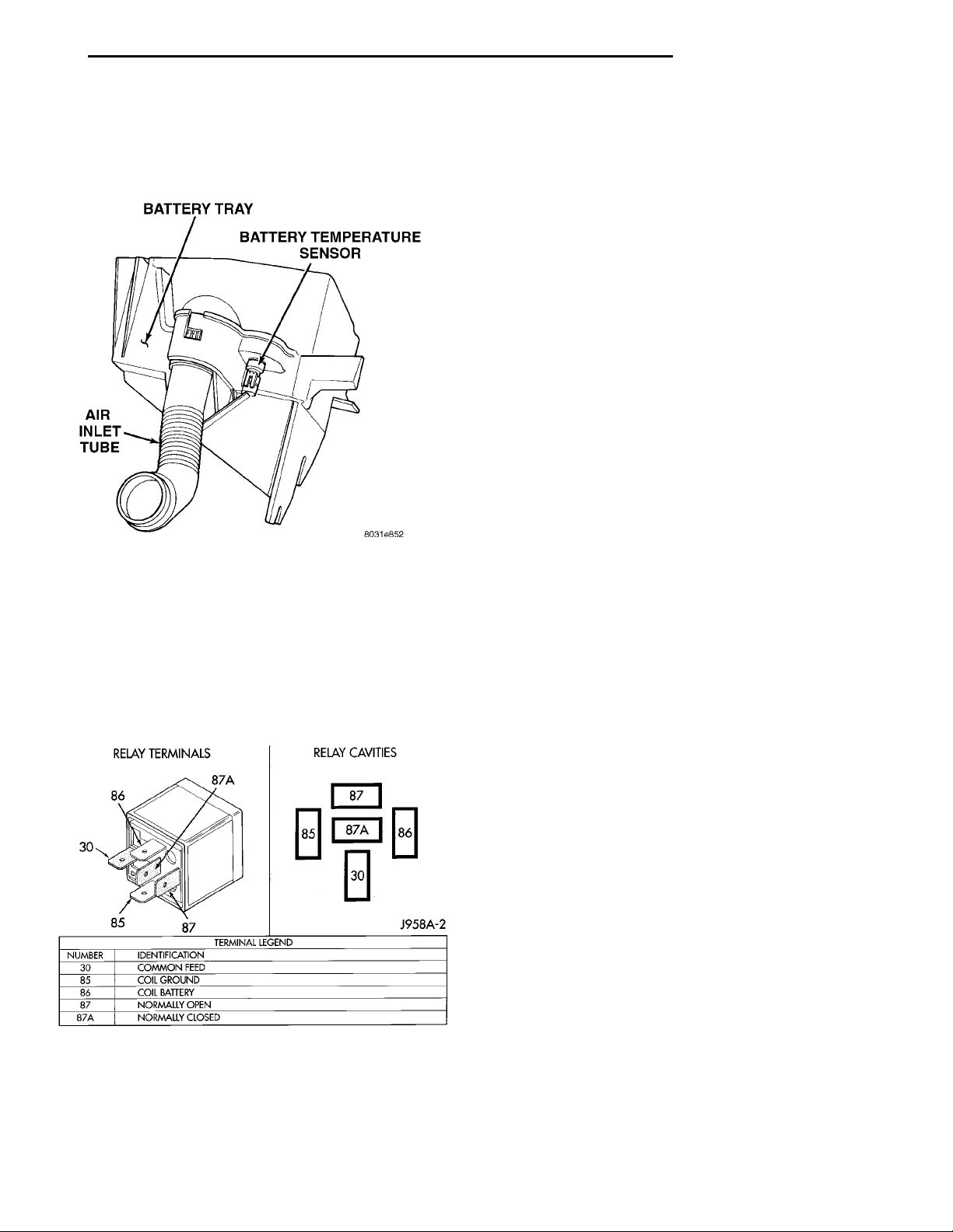
BATTERY TRAYBATTERY TEMPERATURESENSORAIR INLETTUBE
PL FUEL SYSTEM 14 - 47
DIAGNOSIS AND TESTING (Continued)
(24) Inspect the connections to the speed control
servo, if equipped (Fig. 54). Refer to Group 8H, Vehicle Speed Control.
Fig. 76 Battery Temp. Sensor Connectors
(25) Inspect the connection at the battery temperature sensor (Fig. 76).
ASD AND FUEL PUMP RELAYS
RELAY TERMINALSRELAY CAVITIES
The following description of operation and
tests apply only to the Automatic Shutdown
(ASD) and fuel pump relays . The terminals on
the bottom of each relay are numbered (Fig. 77).
• The Powertrain Control Module (PCM) grounds
the coil side of the relay through terminal number
85.
• Terminal number 86 supplies voltage to the coil
side of the relay.
• When PCM de-energizes the ASD and fuel pump
relays, terminal number 87A connects to terminal 30.
This is the Off position. In the off position, voltage is
not supplied to the rest of the circuit. Terminal 87A
is the center terminal on the relay. There is no wire
or terminal in the cavity.
• When the PCM energies ASD and fuel pump
relays energize, terminal 87 connects to terminal 30.
This is the On position. Terminal 87 supplies voltage
to the rest of the circuit.
TESTING
The following procedure applies to the ASD and
fuel pump relays.
(1) Remove relay from connector before testing.
(2) With the relay removed from the vehicle, use
an ohmmeter to check the resistance between terminals 85 and 86 of the relay. The resistance should be
between 75 65 ohms.
(3) Connect the ohmmeter between relay terminals
30 and 87A of the relay. The ohmmeter should show
continuity between terminals 30 and 87A.
(4) Connect the ohmmeter between relay terminals
87 and 30 of the relay. The ohmmeter should not
show continuity at this time.
(5) Connect one end of a jumper wire (16 gauge or
heavier) to relay terminal 85. Connect the other end
of the jumper wire to the ground side of a 12 volt
power source.
(6) Connect one end of another jumper wire (16
gauge or heavier) to the power side of the 12 volt
power source. Do not attach the other end of the
jumper wire to the relay at this time.
Fig. 77 ASD and Fuel Pump Relay Terminals
OPERATION
• Terminal number 30 is connected to battery voltage. For both the ASD relay and fuel pump relays,
terminal 30 is connected to battery voltage at all
times.
WARNING: DO NOT ALLOW OHMMETER TO CONTACT TERMINALS 85 OR 86 DURING THIS TEST.
(7) Attach the other end of the jumper wire to
relay terminal 86. This activates the relay. The ohmmeter should now show continuity between relay terminals 87 and 30. The ohmmeter should not show
continuity between relay terminals 87A and 30.
(8) Disconnect jumper wires.
(9) Replace the relay if it did not pass the continuity and resistance tests. If the relay passed the tests,
it operates properly. Check the remainder of the ASD
and fuel pump relay circuits. Refer to group 8W, Wiring Diagrams.
CAMSHAFT AND CRANKSHAFT POSITION SENSOR
Refer to Group 8D, Ignition for Diagnosis and Testing of Camshaft and Crankshaft Sensors.
Page 48
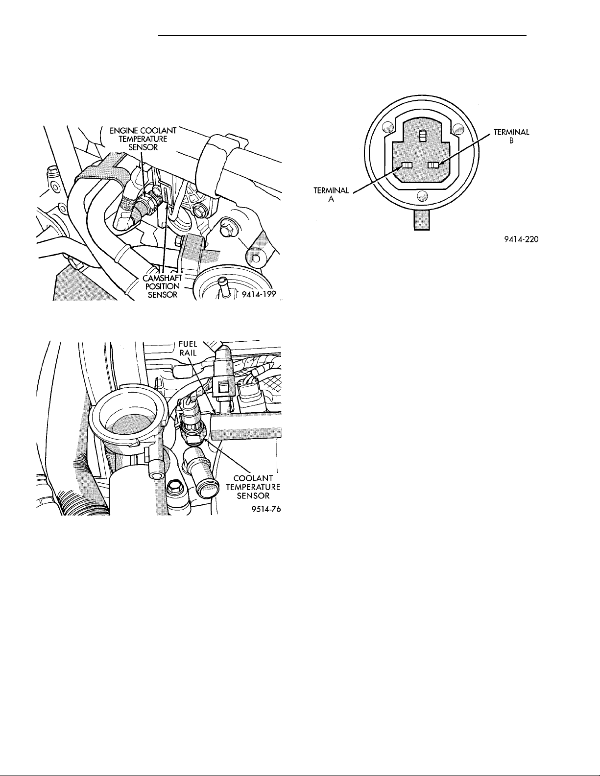
14 - 48 FUEL SYSTEM PL
DIAGNOSIS AND TESTING (Continued)
ENGINE COOLANT TEMPERATURE SENSOR
(1) With the key off, disconnect wire harness connector from coolant temperature sensor (Fig. 78) or
(Fig. 79).
Fig. 80 Engine Coolant Temperature Sensor
greater than 1 ohm, repair the wire harness as necessary.
Fig. 78 Engine Coolant Temperature Sensor
Location—SOHC
Fig. 79 Engine Coolant Temperature Sensor
Location—DOHC
(2) Connect a high input impedance (digital) voltohmmeter to terminals A and B (Fig. 80). The ohmmeter should read as follows:
• Engine/Sensor at normal operating temperature
around 200°F should read approximately 700 to
1,000 ohms.
• Engine/Sensor at room temperature around 70°F
ohmmeter should read approximately 7,000 to 13,000
ohms.
(3) Test the resistance of the wire harness between
the PCM 60-way connector terminal 28 and the sensor harness connector. Also check for continuity
between PCM 60-way connector terminal 51 and the
sensor harness connector. Refer to Group 8W, Wiring
diagrams for circuit information. If the resistance is
HEATED OXYGEN SENSOR
Use an ohmmeter to test the heating element of
the oxygen sensors. Disconnect the electrical connector from each oxygen sensor. The white wires in the
sensor connector are the power and ground circuits
for the heater. Connect the ohmmeter test leads to
terminals of the white wires in the heated oxygen
sensor connector. Replace the heated oxygen sensor if
the resistance is not between 4 and 7 ohms.
IDLE AIR CONTROL (IAC) MOTOR TEST
To preform a complete test of IAC motor and its
circuitry, refer to DRB scan tool and the appropriate
Powertrain Diagnostics Procedures manual.
KNOCK SENSOR
The knock sensor can be tested with a digital voltmeter. Sensor output should be between 80 mV and 4
volts with the engine running between 576 and 2208
rpm. If the output falls outside of this range a DTC
will be set.
MANIFOLD ABSOLUTE PRESSURE (MAP) SENSOR
To perform a complete test of the MAP sensor and
its circuitry, refer to the DRB scan tool and appropriate Powertrain Diagnostics Procedures manual. To
test the MAP sensor only, refer to the following:
CAUTION: When testing the MAP sensor, be sure
that the harness wires are not damaged by the test
meter probes.
(1) Test the MAP sensor output voltage at the
MAP sensor connector between terminals 1 and 4
(Fig. 81). With the ignition switch ON and the engine
not running, output voltage should be 4 to 5 volts.
Page 49
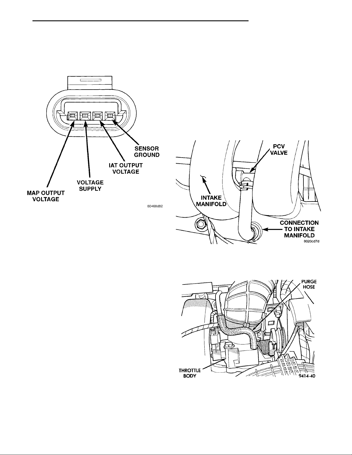
SENSOR GROUNDIAT OUTPUT VOLTAGEVOLTAGE SUPPLYMAP OUTPUT VOLTAGE
THROTTLEBODY
PCV VALVECONNECTION TOINTAKE MANIFOLDINTAKE MANI-FOLD
PURGE
HOSE
PL FUEL SYSTEM 14 - 49
DIAGNOSIS AND TESTING (Continued)
The voltage should drop to 1.5 to 2.1 volts with a hot,
neutral idle speed condition. If OK, go to next step. If
not OK, go to step 3.
Wide-Open-Throttle (WOT). At idle, TPS output voltage should be approximately 0.38 volts to 1.2 volts.
At wide open throttle, TPS output voltage should be
approximately 3.1 volts to 4.4 volts. The output voltage should gradually increase as the throttle plate
moves slowly from idle to WOT.
Check for spread terminals at the sensor and PCM
connections before replacing the TPS.
THROTTLE BODY MINIMUM AIR FLOW
(1) Turn ignition key to Off.
(2) Disconnect the PCV valve hose from the intake
manifold nipple (Fig. 82). Cap the PCV vacuum nipple.
Fig. 81 MAP Sensor Connector
(2) Test PCM terminal 36 for the same voltage
described in the previous step to verify wire harness
condition. Repair as required.
(3) Test the MAP sensor ground circuit at sensor
connector terminal 1 and PCM terminal 43. If OK, go
to next step. If not OK, repair as required.
(4) Test MAP sensor supply voltage between sensor connector terminals 3 and 1 with the key ON.
The voltage should be approximately 5 volts (6.5V).
Five volts (6.5V) should also be at terminal 61 of the
PCM. If OK, replace MAP sensor. If not OK, repair or
replace the wire harness as required.
THROTTLE POSITION SENSOR
To perform a complete test of the this sensor and
its circuitry, refer to the DRB scan tool and appropriate Powertrain Diagnostics Procedures manual. To
test the throttle position sensor only, refer to the following:
The Throttle Position Sensor (TPS) can be tested
with a digital voltmeter (DVM). The center terminal
of the sensor is the output terminal. One of the other
terminals is a 5 volt supply and the remaining terminal is ground.
Connect the DVM between the center and sensor
ground terminal. Refer to Group 8W - Wiring Diagrams for correct pinout.
With the ignition switch in the ON position, check
the output voltage at the center terminal wire of the
connector. Check the output voltage at idle and at
Fig. 82 PCV Vacuum Nipple
(3) Disconnect purge hose from the nipple on the
throttle body (Fig. 83).
Fig. 83 Purge Hose
Page 50
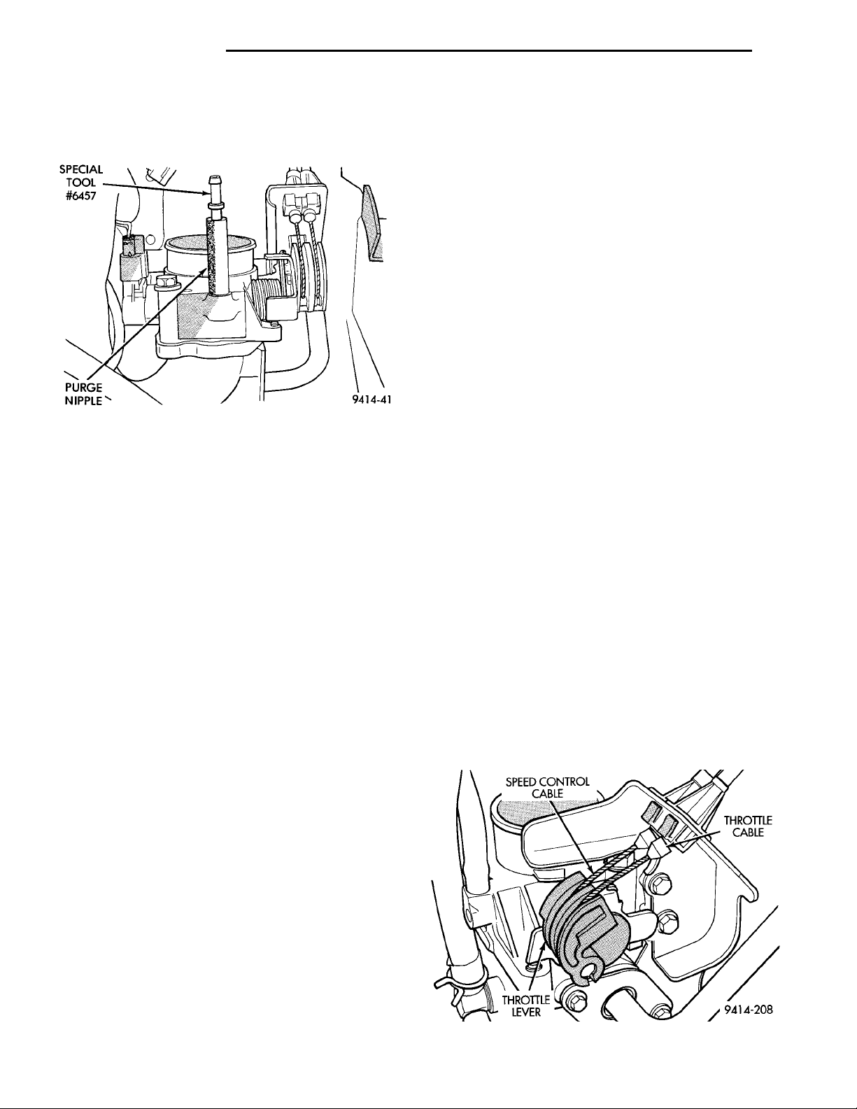
SPECIALTOOL #6457PURGE NIP-PLE
14 - 50 FUEL SYSTEM PL
SPEED CONTROLCABLE THROTTLECABLETHROTTLELEVER
DIAGNOSIS AND TESTING (Continued)
(4) Use a piece of hose to attach Air Metering Orifice 6457 (0.125 in. orifice) to the purge nipple on the
throttle body (Fig. 84).
Fig. 84 Orifice 6457 Attached to Purge Nipple
(5) Ensure that all accessories are off.
(6) Connect the DRB scan tool to the data link
connector inside the passenger compartment.
(7) Run engine in Park or Neutral until the cooling
fan has cycled on and off at least once (180°F).
(8) Using the DRB scan tool, access Minimum Airflow Idle Speed.
(9) The following will then occur:
• Idle air control motor will fully close
• Idle spark advance will become fixed
• PCM will go open loop enriched
• DRB scan tool displays engine RPM
(10) If idle RPM is within the range shown in the
Idle Specification chart, throttle body minimum airflow is set correctly.
IDLE SPECIFICATION —2.0L ENGINE
Odometer Reading Idle RPM
Below 1000 Miles ...............550–1300 RPM
Above 1000 Miles ...............600–1300 Miles
(b) While holding the throttle open, spray the
entire throttle body bore and the manifold side of
the throttle plate with Mopar Parts Cleaner. Only
use Mopar Parts Cleaner to clean the throttle
body.
(c) Using a soft scuff pad, clean the top and bottom of throttle body bore and the edges and manifold side of the throttle blade. The edges of the
throttle blade and portions of the throttle
bore that are closest to the throttle blade
when closed, must be free of deposits.
(d) Use compressed air to dry the throttle body.
(e) Inspect throttle body for foreign material.
(f) Install throttle body on manifold.
(g) Repeat steps 1 through 14. If the minimum
air flow is still not within specifications, the problem is not caused by the throttle body.
(12) Shut off engine.
(13) Remove Air Metering Orifice 6457. Install
purge hose.
(14) Remove cap from PCV valve. Connect hose to
PCV valve.
(15) Remove DRB scan tool.
VEHICLE SPEED SENSOR
To perform a complete test of the sensor and its
circuitry, refer to the DRB scan tool and appropriate
Powertrain Diagnostics Procedures Manual.
REMOVAL AND INSTALLATION
THROTTLE BODY—MANUAL TRANSMISSION
Remove throttle body cables using the following
procedures.
REMOVAL
(1) Remove throttle cable cover.
(2) Remove throttle cable from the throttle body
cam (Fig. 85) and (Fig. 86).
(11) If idle RPM is above specifications, use the
DRB scan tool to check idle air control motor operation. If idle air control motor is OK, replace throttle
body. If idle air flow is below specification, shut off
the engine and clean the throttle body as follows:
WARNING: CLEAN THROTTLE BODY IN A WELL
VENTILATED AREA. WEAR RUBBER OR BUTYL
GLOVES, DO NOT LET MOPAR PARTS CLEANER
COME IN CONTACT WITH EYES OR SKIN. AVOID
INGESTING THE CLEANER. WASH THOROUGHLY
AFTER USING CLEANER.
(a) Remove the throttle body from engine.
Fig. 85 Throttle Cable Attachment to Throttle Body
Page 51
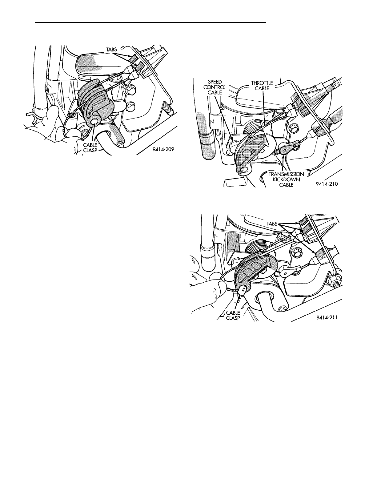
CLASP
TABSCABLE
SPEED CON-TROL CABLE THROTTLECABLETRANSMISSIONKICKDOWNCABLE
TABSCABLECLASP
PL FUEL SYSTEM 14 - 51
REMOVAL AND INSTALLATION (Continued)
(2) Remove throttle body cables using the following
procedures.
(3) Remove throttle cable from throttle body cam
(Fig. 87) and (Fig. 88).
Fig. 86 Disconnecting Throttle Cable
(3) Compress the retaining tabs on the cable and
slide cable out of bracket (Fig. 86).
(4) If equipped with speed control, remove speed
control cable from throttle lever by sliding clasp out
hole used for throttle cable.
(5) Remove 2 screws holding cable mounting
bracket and support bracket.
(6) Remove TPS connector.
(7) Remove Idle Air Control motor connector.
(8) Remove the EVAP purge hose.
(9) Remove throttle body mounting bolts. Remove
throttle body.
(10) The rubber O-ring gasket on the intake manifold is reusable. Wipe the O-ring clean before installing throttle body (Fig. 91).
Fig. 87 Throttle Body Cables Attachment to Throttle
Body
INSTALLATION
(1) Install throttle body on intake manifold.
Tighten mounting bolts.
(2) Attach cable mounting bracket and support
bracket with 2 screws.
(3) Connect the electrical connetion to the throttle
body.
(4) Connect the EVAP purge hose to the throttle
body.
(5) Install cable housing(s) retainer tabs into
bracket.
(6) If equipped with speed control, rotate the throttle lever forward to the wide open position and
install speed control cable clasp (Fig. 86).
(7) Rotate throttle lever to wide open position and
install throttle cable clasp (Fig. 86).
(8) Install throttle cable cover. Tighten bolt to 5.6
N·m (50 ins. lbs.).
THROTTLE BODY—AUTOMATIC TRANSMISSION
REMOVAL
(1) Remove throttle cable cover.
Fig. 88 Disconnecting Throttle Cable
(4) Compress the retaining tabs on the cable and
slide cable out of bracket (Fig. 88).
(5) Hold throttle lever in the wide open position.
Using finger pressure only, remove kickdown cable by
PUSHING connector off the lever nail head (Fig. 87)
and (Fig. 89). DO NOT try to pull connector off perpendicular to the lever.
(6) Compress the retaining tabs on the cable and
slide cable out of bracket (Fig. 88).
(7) if equipped with speed control, hold throttle
lever in the wide open position. Using finger pressure
only, remove speed control cable by PUSHING connector off the lever nail head (Fig. 87) and (Fig. 90).
DO NOT try to pull connector off perpendicular to
the lever.
Page 52
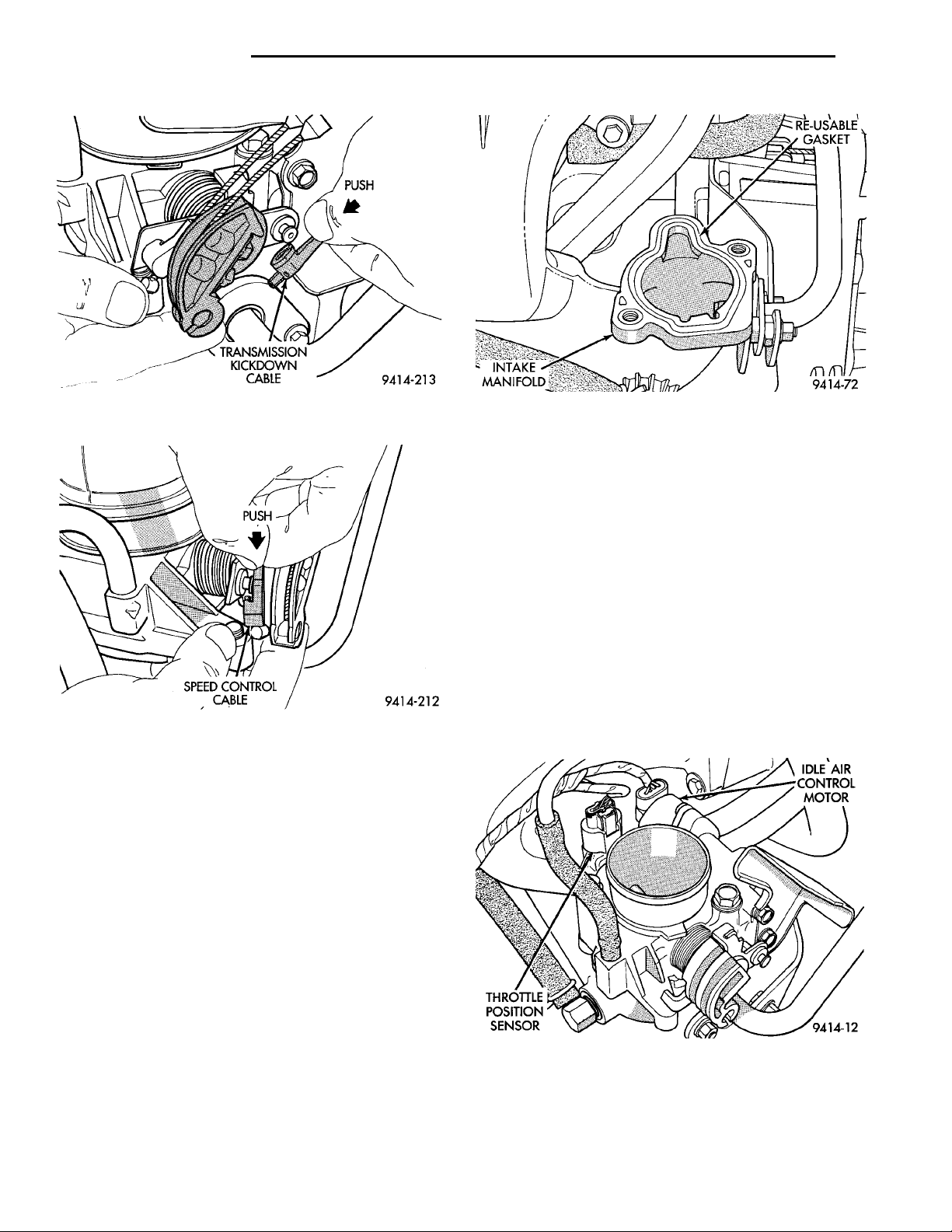
PUSHSPEED CONTROL CABLE
PUSHTRANSMISSION KICK-DOWN CABLE
INTAKEMANIFOLD
THROTTLEPOSITIONSENSOR
RE-USABLE
IDLE AIR CON-
GASKET
TROL MOTOR
14 - 52 FUEL SYSTEM PL
REMOVAL AND INSTALLATION (Continued)
Fig. 89 Transmission Kickdown Cable Connector
Fig. 90 Speed Control Cable Connector
(8) Compress the retaining tabs on the cable and
slide cable out of bracket (Fig. 88).
(9) Remove 2 screws holding cable mounting
bracket and support bracket.
(10) Remove TPS connector.
(11) Remove Idle Air Control motor connector.
(12) Remove EVAP purge hose.
(13) Remove throttle body mounting bolts. Remove
throttle body.
(14) The rubber O-ring gasket on the intake manifold is reusable. Wipe the O-ring clean before installing throttle body (Fig. 91).
Fig. 91 Re-Usable Throttle Body Gasket
(6) Install throttle body cables using the following
procedures.
(7) From the engine compartment, rotate the
throttle lever forward to the wide open position and
install throttle cable clasp (Fig. 88).
(8) If equipped with speed control, rotate throttle
lever forward to the wide open position and slide
speed control cable connector onto nail head.
(9) Rotate throttle lever forward to the wide open
position and slide kickdown cable connector onto nail
head.
(10) Install throttle cable cover. Tighten bolt to 5.6
N·m (50 ins. lbs.).
THROTTLE POSITION SENSOR (TPS)
The throttle position sensor attaches to the side of
the throttle body (Fig. 92).
INSTALLATION
(1) Install throttle body on intake manifold.
Tighten mounting bolts.
(2) Attach cable mounting bracket and support
bracket with 2 screws.
(3) Connect electrical connection to throttle body.
(4) Connect the EVAP purge hose.
(5) Install cable housing(s) retainer tabs into
bracket.
Fig. 92 Throttle Position Sensor and Idle Air Control
Motor
REMOVAL
(1) Disconnect EVAP purge hose from throttle body.
Page 53
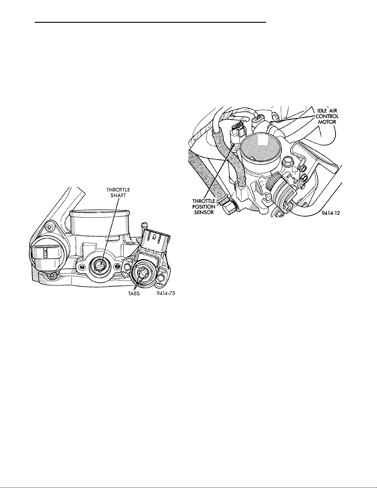
PL FUEL SYSTEM 14 - 53
REMOVAL AND INSTALLATION (Continued)
(2) Disconnect electrical connector from idle air
control motor and throttle position sensor.
(3) Remove throttle body. Refer to Throttle Body in
this section.
(4) Remove throttle position sensor mounting screws.
(5) Remove throttle position sensor.
INSTALLATION
(1) The throttle shaft end of the throttle body slides
into a socket in the TPS (Fig. 93). The socket has two
tabs inside it. The throttle shaft rests against the
tabs. When indexed correctly, the TPS can rotate
clockwise a few degrees to line up the mounting screw
holes with the screw holes in the throttle body. The
TPS has slight tension when rotated into position. If it
is difficult to rotate the TPS into position, install the
sensor with the throttle shaft on the other side of the
tabs in the socket. Tighten mounting screws to 2 N·m
(17 in. lbs.) torque.
(2) Remove electrical connector from idle air con-
trol motor and throttle position sensor.
(3) Remove the EVAP purge hose from the throttle
body.
(4) Remove throttle body. Refer to Throttle Body in
this section.
(5) Remove idle air control motor mounting screws
(Fig. 94).
Fig. 93 Throttle Position Sensor Installation
(2) After installing the TPS, the throttle plate
should be closed. If the throttle plate is open, install
the sensor on the other side of the tabs in the socket.
(3) Install throttle body. Refer to Throttle Body in
this section.
(4) Attach electrical connectors to idle air control
motor and throttle position sensor.
(5) Install EVAP purge hose to throttle body nipple.
IDLE AIR CONTROL MOTOR
When servicing throttle body components, always
reassemble components with new O-rings and seals
where applicable. Never use lubricants on O-rings or
seals, damage may result. If assembly of component is
difficult, use water to aid assembly. Use care when
removing hoses to prevent damage to hose or hose
nipple.
REMOVAL
(1) Disconnect negative cable from battery.
Fig. 94 Servicing Idle Air Control Motor
(6) Remove motor from throttle body. Ensure the
O-ring is removed with the motor.
INSTALLATION
(1) The new idle air control motor has a new
O-ring installed on it. If pintle measures more than 1
inch (25 mm) it must be retracted. Use the DRB Idle
Air Control Motor Open/Close Test to retract the
pintle (battery must be connected.)
(2) Carefully place idle air control motor into
throttle body.
(3) Install mounting screws. Tighten screws to 2
N·m (17 in. lbs.) torque.
(4) Install throttle body. Refer to Throttle Body in
this section.
(5) Connect electrical connector to idle air control
motor and throttle position sensor.
(6) Connect the EVAP purge hose to the throttle
body nipple.
(7) Connect negative cable to battery.
MAP/IAT SENSOR—SOHC
The MAP/IAT sensor attaches to the intake manifold plenum (Fig. 95).
REMOVAL
(1) Disconnect the electrical connector from the
MAP/IAT sensor.
(2) Remove sensor mounting screws.
(3) Remove sensor.
Page 54
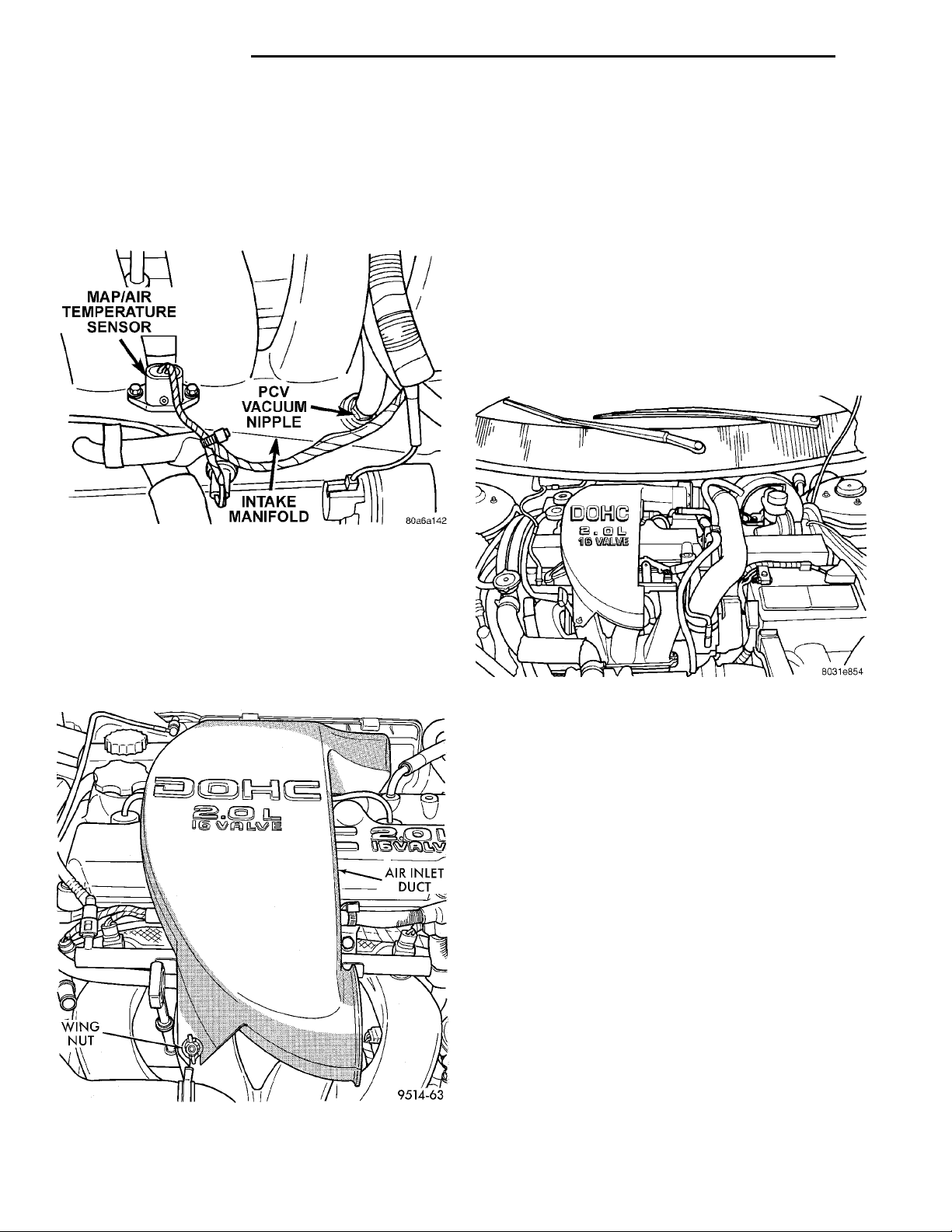
14 - 54 FUEL SYSTEM PL
REMOVAL AND INSTALLATION (Continued)
INSTALLATION
(1) Insert sensor into intake manifold while mak-
ing sure not to damage O-ring seal.
(2) Tighten mounting screws to 2 N·m (20 in. lbs)
torque for plastic manifold and 3 N·m (30 in. lbs.) for
aluminum manifold.
(3) Attach electrical connector to sensor.
Fig. 95 MAP/IAT Sensor—SOHC
(2) Disconnect the electrical connector from the
MAP/IAT sensor.
(3) Remove sensor mounting screws.
(4) Remove sensor.
INSTALLATION
(1) Insert sensor into intake manifold while mak-
ing sure not to damage O-ring seals.
(2) Tighten mounting screws to 2 N·m (20 in. lbs)
torque foe a plastic manifold and 3 N·m (30 in. lbs)
for a aluminum manifold.
(3) Attach electrical connector to sensor.
(4) Install air inlet duct wing nut and duct from
intake manifold, insure that the duct does not interfer with ignition cables.
MAP/IAT SENSOR—DOHC
The MAP/IAT sensor attaches to the intake mani-
fold plenum (Fig. 97).
REMOVAL
(1) Remove air inlet duct wing nut and duct from
intake manifold (Fig. 96).
WING NUTAIR INLETDUCT
Fig. 97 MAP/IAT Sensor—DOHC
DUTY CYCLE EVAP PURGE SOLENOID VALVE
The solenoid attaches to a bracket near the front
engine mount (Fig. 98). The solenoid will not operate
unless it is installed correctly.
REMOVAL
(1) Disconnect electrical connector from solenoid.
(2) Disconnect vacuum tubes from solenoid.
(3) Remove solenoid from bracket.
INSTALLATION
The top of the solenoid has TOP printed on it. The
solenoid will not operate unless it is installed correctly.
(1) Install solenoid on bracket.
(2) Connect vacuum tube to solenoid.
(3) Connect electrical connector to solenoid.
Fig. 96 Air Inlet Duct—DOHC
POWERTRAIN CONTROL MODULE (PCM)
The PCM attaches to the inner fender panel next
to the washer fluid bottle on the passenger side (Fig.
99).
Page 55
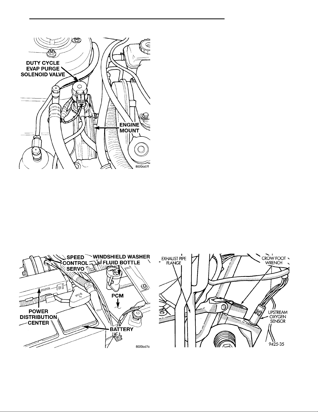
DUTY CYCLE EVAPPURGE SOLENOIDVALVE ENGINEMOUNT
SPEED CON-TROL SERVO WINDSHIELDWASHER FLUIDBOTTLEPCMBATTERYPOWER DISTRI-BUTION CEN-TER
PL FUEL SYSTEM 14 - 55
REMOVAL AND INSTALLATION (Continued)
(3) Install PDC by pushing down into brackets.
(4) Install washer bottle neck.
(5) Connect positive cable to battery.
(6) Connect negative cable to battery.
CRANKSHAFT POSITION SENSOR
For removal/installation procedures refer to group
8D - Ignition System, Service Procedures.
CAMSHAFT POSITION SENSOR
For removal/installation procedures refer to group
8D - Ignition System, Service Procedures.
UPSTREAM HEATED OXYGEN SENSOR
REMOVAL
(1) Raise and support vehicle.
(2) Unplug sensor connector.
(3) Remove sensor using an oxygen sensor crow
foot wrench such as Snap-On tool YA8875 or equivalent (Fig. 100).
(4) After removing the sensor, the exhaust manifold threads must be cleaned with an 18 mm X 1.5 +
Fig. 98 Duty Cycle EVAP Purge Solenoid Valve
REMOVAL
(1) Disconnect negative cable from battery.
(2) Disconnect positive cable from battery.
(3) Remove washer bottle neck.
(4) Squeeze tabs on PDC while pulling PDC up to
remove it from bracket. Lay PDC aside to gain access
to PCM bracket screws.
(5) Remove screws attaching PCM to body.
(6) Lift PCM up and disconnect the 2 40-way connector.
(7) Remove PCM.
6E tap. If reusing the original sensor, coat the sensor
threads with an anti-seize compound such as Loctitet
771-64 or equivalent.
INSTALLATION
New sensors have compound on the threads and do
not require an additional coating.
(1) Install sensor using an oxygen sensor crow foot
EXHAUSTPIPEFLANGE CROW FOOTWRENCHUPSTREAMOXYGEN SEN-SOR
wrench such as Snap-On tool YA8875 or equivalent
(Fig. 100). Tighten the sensor to 28 N·m (20 ft. lbs.)
torque.
(2) Plug sensor connector.
(3) Lower vehicle.
Fig. 99 Powertrain Control Module
INSTALLATION
(1) Attach the 2 40-way connector to PCM.
(2) Install PCM. Tighten mounting screws to 9
N·m (80 in. lbs.) torque.
Fig. 100 Upstream Heated Oxygen Sensor Removal/
Installation
Page 56
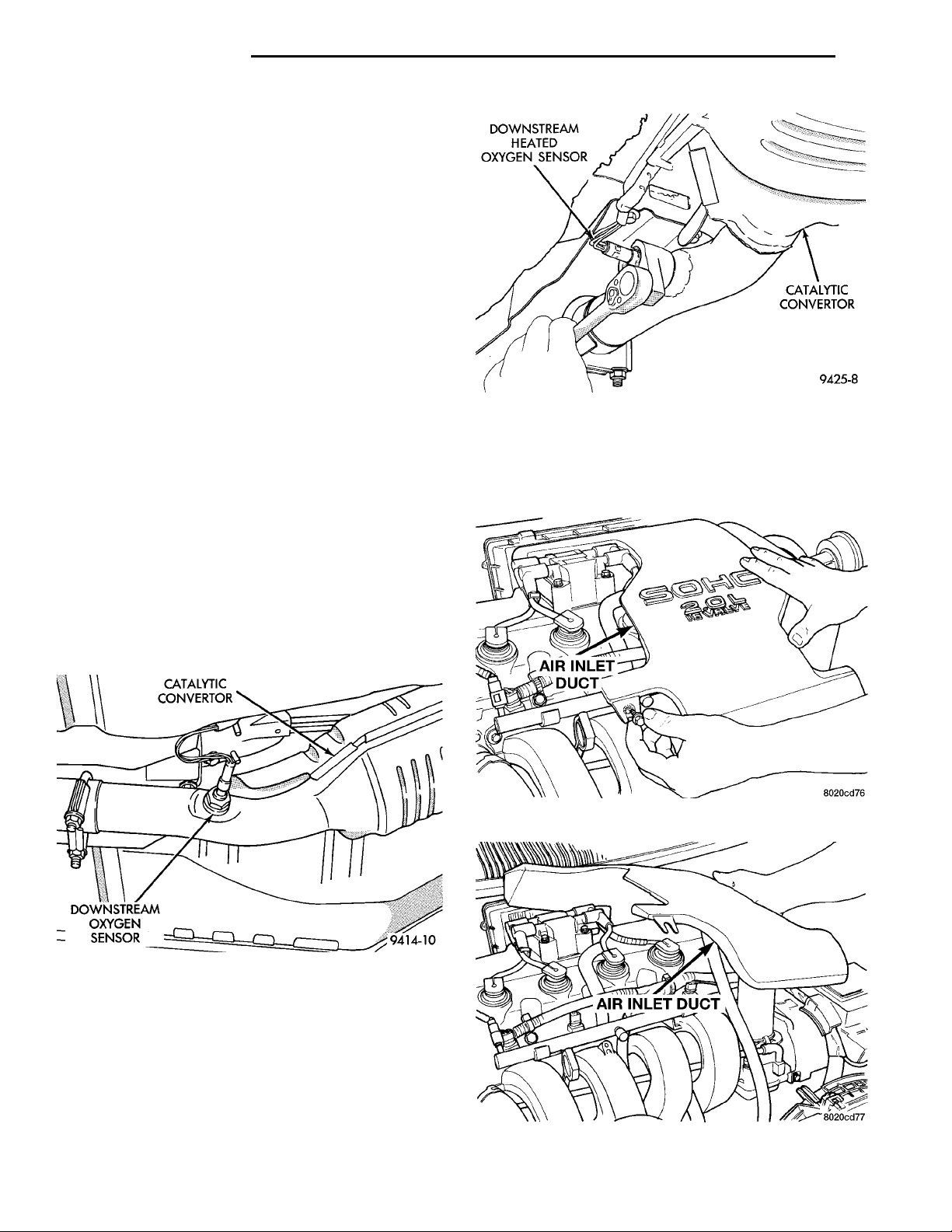
DOWNSTREAMHEATED OXYGENSENSOR CATALYTICCONVERTOR
14 - 56 FUEL SYSTEM PL
REMOVAL AND INSTALLATION (Continued)
DOWNSTREAM HEATED OXYGEN SENSOR
The downstream heated oxygen sensor threads into
the exhaust outlet pipe behind the catalytic convertor
(Fig. 101).
REMOVAL
(1) Raise vehicle.
(2) Disconnect electrical connector from sensor.
(3) Disconnect sensor electrical harness from clips
along body.
(4) Remove sensor using an oxygen sensor crow
foot wrench such as Snap-On tool YA8875 or equivalent (Fig. 102).
(5) After removing the sensor, the exhaust manifold threads must be cleaned with an 18 mm X 1.5 +
6E tap. If reusing the original sensor, coat the sensor
threads with an anti-seize compound such as Loctitet
771-64 or equivalent.
INSTALLATION
New sensors have compound on the threads and do
not require an additional coating.
(1) Install sensor using an oxygen sensor crow foot
wrench such as Snap-On tool YA8875 or equivalent
(Fig. 102). Tighten the sensor to 28 N·m (20 ft. lbs.)
torque.
(2) Connect sensor electrical harness from clips
along body.
(3) Connect electrical connector from sensor.
(4) Lower vehicle.
Fig. 102 Downstream Heated Oxygen Sensor
Removal/Installation
REMOVAL
(1) Remove air intake tube (Fig. 103) from air
cleaner and intake manifold (Fig. 104).
Fig. 101 Downstream Heated Oxygen Sensor
AIR CLEANER ELEMENT
Neon vehicles do not use a heated air inlet system.
The PCM adjusts fuel injector pulse width and ignition timing to compensate for different ambient temperatures.
The air cleaner attaches to a bracket on the rear of
the cylinder head. An ambient air duct supplies
underhood air for the engine.
AIR INLET DUCT
Fig. 103 Air Intake Duct
Fig. 104 Removal/Installation of Air Inlet Duct
Page 57
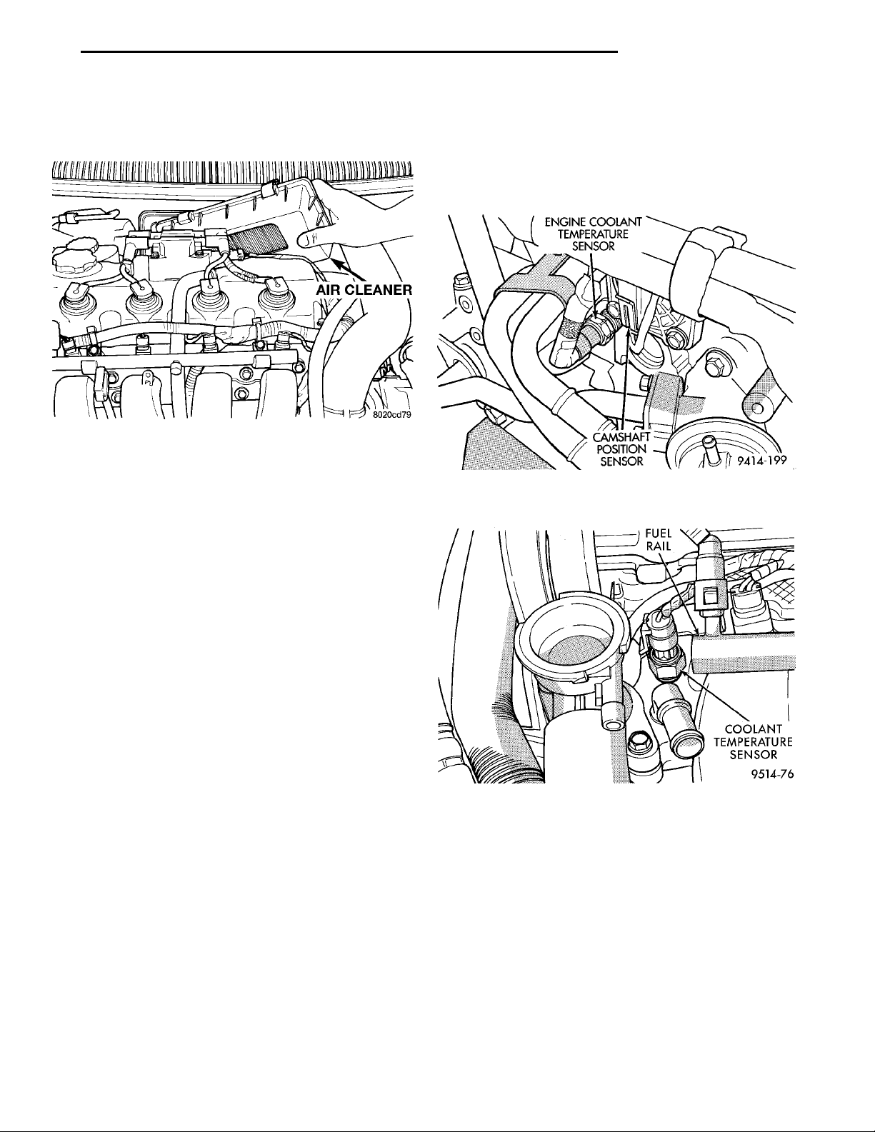
AIR CLEANER
PL FUEL SYSTEM 14 - 57
REMOVAL AND INSTALLATION (Continued)
(2) Unfasten clasps on top of air cleaner housing.
Rotate front of housing forward then lift front away
from air cleaner housing (Fig. 105).
Fig. 105 Removal/Installation Air Cleaner Front
Housing and Element
(3) Remove air cleaner element from front housing
(Fig. 105).
INSTALLATION
(1) Install air cleaner element into front housing.
(2) Rotate front of housing forward then lower into
place and locate tabs in slots. Fasten clasps on top of
air cleaner housing.
(3) Install air intake duct at air cleaner and intake
manifold.
INSTALLATION
(1) Install coolant sensor. Tighten sensor to 18
ENGINE COOLANTTEMPERATURESENSORCAMSHAFTPOSITIONSENSOR
FUEL RAIL
COOLANT TEMPER-ATURE SENSOR
N·m (165 in. lbs.) torque.
(2) Attach electrical connector to sensor.
(3) Fill cooling system. Refer to Group 7, Cooling
System.
Fig. 106 Engine Coolant Temperature Sensor—
SOHC
ENGINE COOLANT TEMPERATURE SENSOR
The engine coolant temperature sensor threads
into the rear of the cylinder head (Fig. 106) or (Fig.
107).
REMOVAL
(1) With the engine cold, drain coolant until level
drops below cylinder head. Refer to Group 7, Cooling
System.
(2) Disconnect coolant sensor electrical connector.
(3) Remove coolant sensor.
Fig. 107 Engine Coolant Temperature Sensor—
DOHC
Page 58
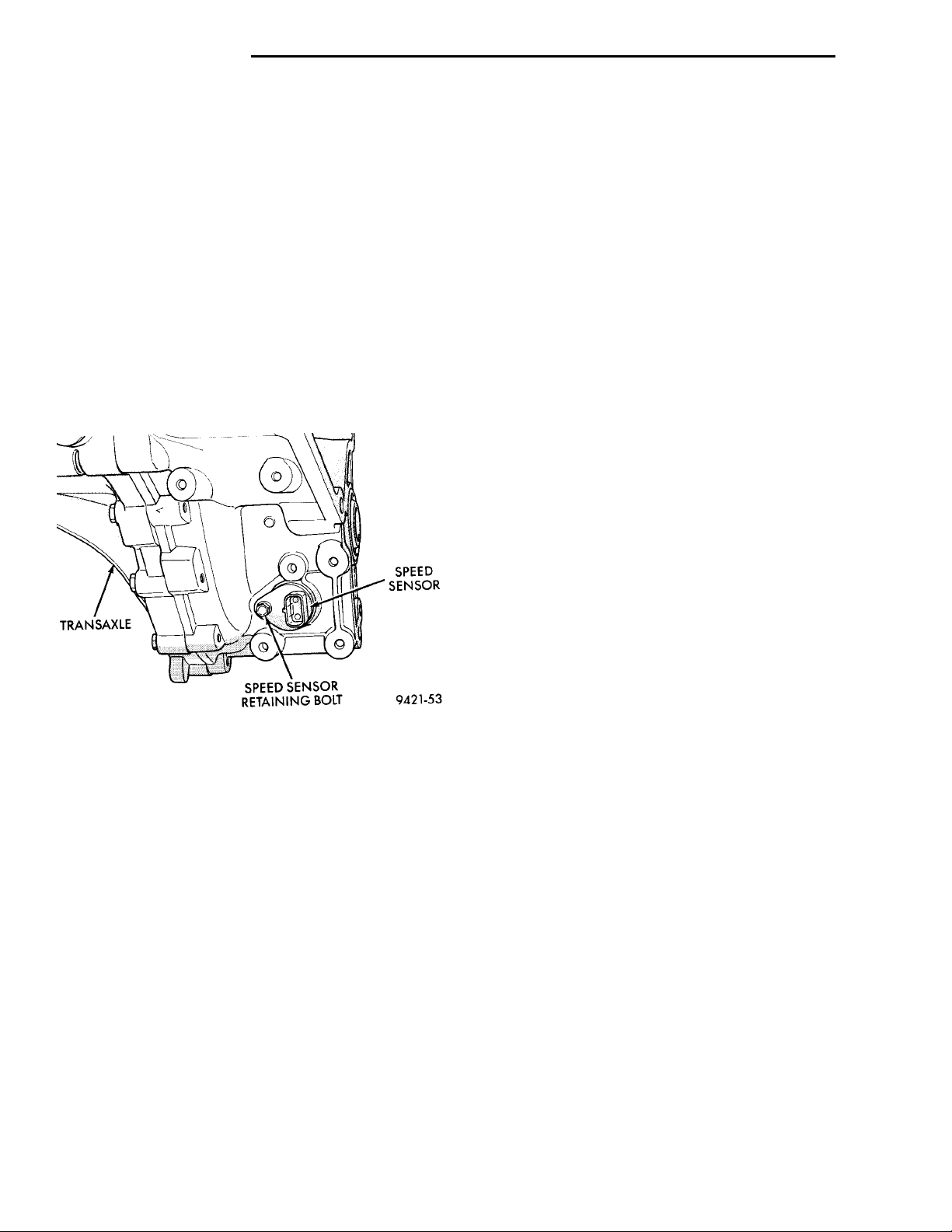
TRANSAXLE SPEEDSENSORSPEED SENSOR RETAININGBOLT
14 - 58 FUEL SYSTEM PL
REMOVAL AND INSTALLATION (Continued)
VEHICLE SPEED SENSOR
The vehicle speed sensor is located in the transmission extension housing (Fig. 108).
REMOVAL
(1) Disconnect electrical connector from sensor.
(2) Remove the sensor mounting bolt.
(3) Lift the sensor out of the transaxle extension
housing. Ensure the O-ring was removed with the
sensor.
INSTALLATION
The speed sensor gear meshes with a gear on the
output shaft.
(1) With O-ring in place, install sensor.
(2) Install mounting bolt.
(3) Connect electrical connector to sensor.
Fig. 108 Vehicle Speed Sensor
KNOCK SENSOR
For removal/installation procedures refer to Group
8D- Ignition System, Service Procedures.
SPECIFICATIONS
VECI LABEL
If anything differs between the specifications found
on the Vehicle Emission Control Information (VECI)
label and the following specifications, use specifications on VECI label. The VECI label is located in the
engine compartment.
TORQUE SPECIFICATIONS
DESCRIPTION TORQUE
Air Cleaner Wingnut .........1.5N·m(15in.lbs.)
Air Cleaner Mount. Stud-To-
Thrott. Body .............10N·m(90in.lbs.)
Crankshaft Position Sensor
Mounting Bolts ............8N·m(70in.lbs.)
Engine Coolant Temperature
Sensor .................18N·m(165 in. lbs.)
IAC Motor-To-Throttle Body
Bolts ....................7N·m(60in.lbs.)
MAP/IAT Sensor .............2N·m(20in.lbs.)
MAP/IAT Sensor .............3N·m(30in.lbs.)
Oxygen Sensor ..............28N·m(20ft.lbs.)
Powertrain Control Module
(PCM) Mounting Screws .....4N·m(35in.lbs.)
Throttle Body Mounting Bolts . 23 N·m (200 in. lbs.)
Throttle Position Sensor
Mounting Screws ...........2N·m(20in.lbs.)
Vehicle Speed Sensor
Mounting Bolt ............2.2N·m(20in.lbs.)
Page 59
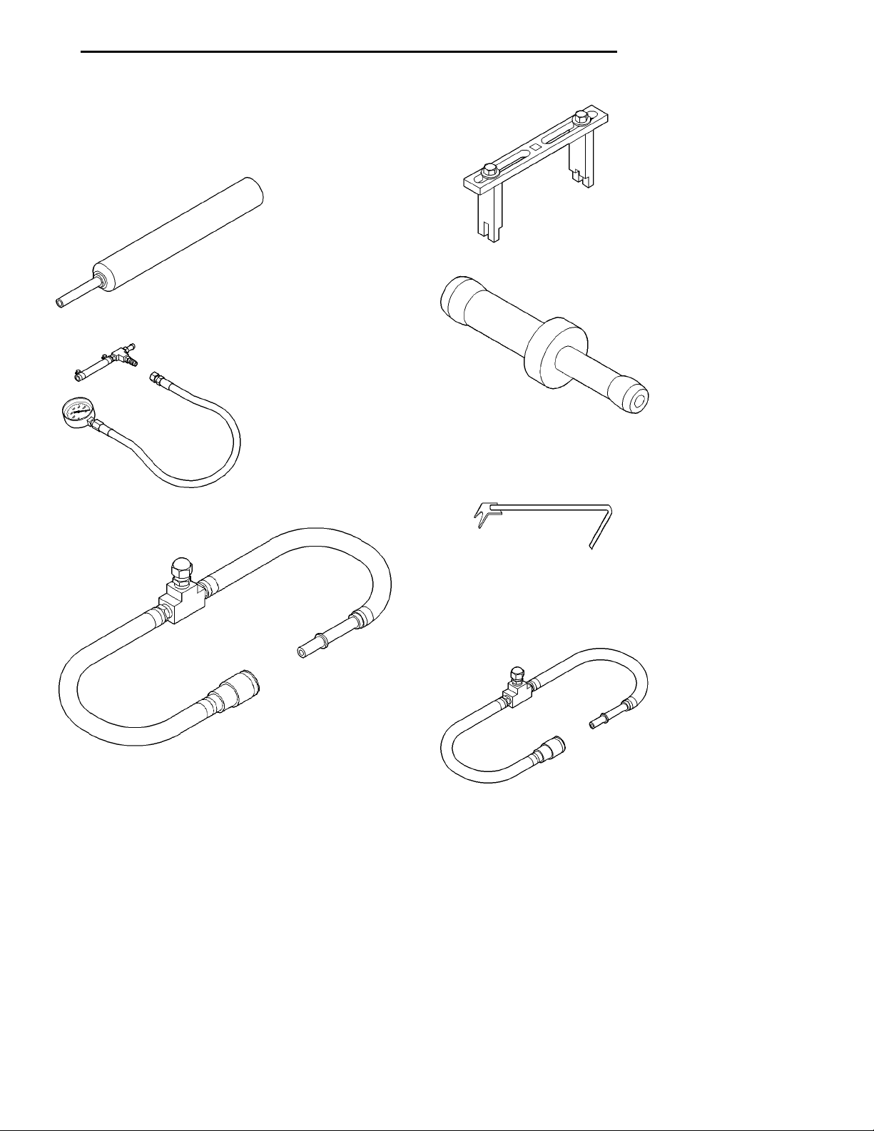
PL FUEL SYSTEM 14 - 59
SPECIAL TOOLS
FUEL
Spanner Wrench 6856
Extractor C–4334
Metering Orifice
Pressure Gauge Assembly C–4799–B
Fuel Pressure Test Adapter 6539
Fuel Line Tool
Fuel Line Adapter
Page 60

14 - 60 FUEL SYSTEM PL
SPECIAL TOOLS (Continued)
Fuel Line Adapter 1/4
 Loading...