

Page 1
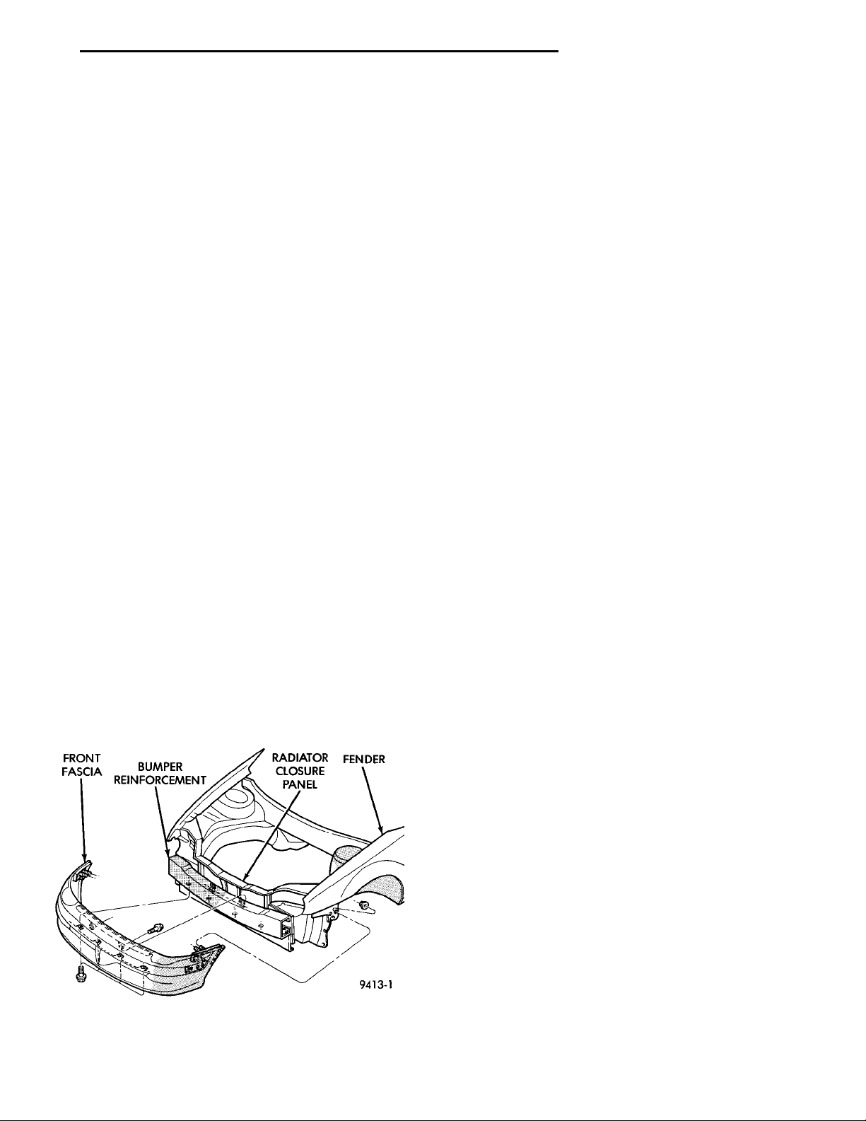
FRONT FASCIA BUMPERREIN-FORCE-MENT RADIATOR CLOSUREPANEL FENDER
PL FRAME AND BUMPERS 13 - 1
FRAME AND BUMPERS
CONTENTS
page page
BUMPERS .............................. 1 FRAMES ............................... 3
BUMPERS
INDEX
page page
REMOVAL AND INSTALLATION
FRONT BUMPER FASCIA ................. 1
FRONT BUMPER REINFORCEMENT ......... 1
REMOVAL AND INSTALLATION
FRONT BUMPER FASCIA
REMOVAL
(1) Remove nuts holding front bumper fascia
bracket to bottom of fender forward of front wheels.
(2) Remove screws holding front fascia to inner
wheelhouse.
(3) Remove bolts holding fascia to bumper rein-
forcement forward of radiator (Fig. 1).
(4) Remove bolts holding fascia to bottom of
bumper reinforcement.
(5) Separate fascia from vehicle.
REAR BUMPER FASCIA .................. 1
REAR BUMPER REINFORCEMENT .......... 2
INSTALLATION
(1) Position fascia on vehicle.
(2) Install bolts holding fascia to bottom of bumper
reinforcement.
(3) Install bolts holding fascia to bumper reinforce-
ment forward of radiator (Fig. 1).
(4) Install screws holding front fascia to inner
wheelhouse.
(5) Install radiator grille, refer to Group 23, Body
for proper procedures.
FRONT BUMPER REINFORCEMENT
REMOVAL
(1) Remove front fascia.
(2) Support bumper reinforcement on a suitable
lifting device.
(3) Remove nuts holding reinforcement to radiator
closure panel (Fig. 2).
(4) Separate bumper reinforcement from vehicle.
Fig. 1 Front Bumper Fascia
INSTALLATION
Reverse the preceding operation.
REAR BUMPER FASCIA
REMOVAL
(1) Release trunk lock and open trunk lid.
(2) Remove bolts holding fascia to tail closure
panel.
(3) Remove push–in fasteners holding fascia to
bottom of rear bumper reinforcement (Fig. 3).
Page 2
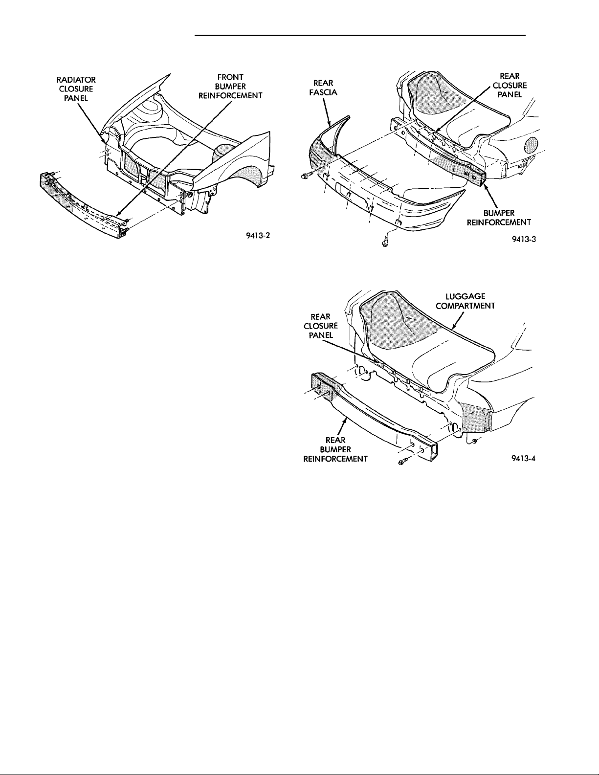
RADIATOR CLOSUREPANEL FRONT BUMPER REIN-FORCEMENT
13 - 2 FRAME AND BUMPERS PL
REMOVAL AND INSTALLATION (Continued)
REAR CLOSUREPANELREAR BUMPER REIN-FORCEMENT LUGGAGE COMPART-MENT
Fig. 2 Front Bumper Reinforcement
(4) Remove bolts holding fascia bracket to lower
quarter panels.
(5) Separate fascia from vehicle.
INSTALLATION
(1) Position fascia on vehicle.
(2) Install bolts holding fascia bracket to lower
quarter panels.
(3) Install push–in fasteners holding fascia to bot-
tom of rear bumper reinforcement (Fig. 3).
(4) Install bolts holding fascia to tail closure panel.
REAR BUMPER REINFORCEMENT
REMOVAL
(1) Remove rear fascia.
(2) Support bumper reinforcement on a suitable
lifting device.
(3) Remove nuts holding reinforcement to rear clo-
sure panel (Fig. 4).
Fig. 3 Rear Bumper Fascia
(4) Separate bumper reinforcement from vehicle.
Fig. 4 Rear Bumper Reinforcement
INSTALLATION
Reverse the preceding operation.
Page 3
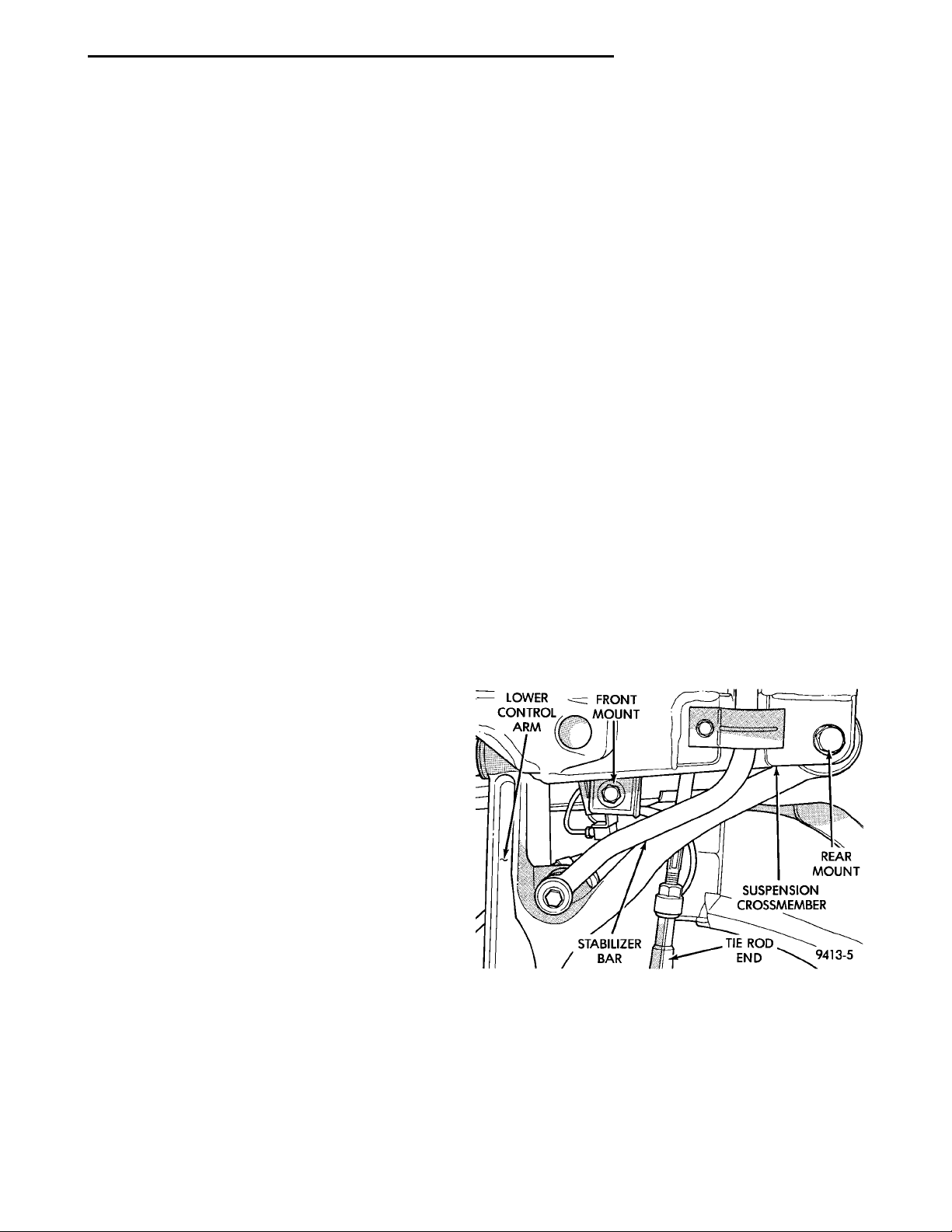
LOWER CON-TROL ARM FRONT MOUNTSTABILIZER BAR TIE RODENDSUSPENSION CROSS-MEMBERREAR MOUNT
PL FRAME AND BUMPERS 13 - 3
FRAMES
INDEX
page page
REMOVAL AND INSTALLATION
FRONT SUSPENSION CROSSMEMBER ...... 3
SPECIFICATIONS
STRUCTURAL DIMENSIONS ............... 5
REMOVAL AND INSTALLATION
FRONT SUSPENSION CROSSMEMBER
WARNING: IF SUSPENSION CROSSMEMBER IS
REPLACED DUE TO COLLISION DAMAGE, INSPECT
THE STEERING COLUMN TO STEERING GEAR
COUPLING FOR DAMAGE. REFER TO GROUP 19,
STEERING FOR INSTRUCTIONS.
Before removing front suspension crossmem-
ber, index mark location of crossmember on
frame to aid installation .
The front suspension crossmember must be properly installed to achieve design camber, caster settings and wheel stagger. The crossmember can be
installed out of position on the frame rails due to its
design. Bolts and cage nuts hold the rear of the
crossmember to the frame torque boxes. Bolts and
J-nuts hold the front of the crossmember to the
frame rails. No designed in locating device is used to
position the crossmember in the vehicle. Before
removing the crossmember mark the frame torque
box around the rear mounting location to aid installation. A crossmember that is removed during service
must be installed in the same position from which it
was removed. To verify that crossmember is in the
proper position, refer to the dimensions provided.
Front end dimensions are gauged from the principal
locating point (PLP) holes located under the frame
torque boxes rearward of the front wheels. After
removal and installation of the crossmember is performed, verify that front suspension alignment is
within specifications. If camber, caster settings and
wheel stagger is not within specifications, loosen and
reposition crossmember to bring suspension within
specifications. Refer to Group 2, Front Suspension
and Driveshaft for additional information.
REMOVAL
(1) Hoist and support vehicle on safety stands.
(2) Using a suitable marking device, mark the outline of the suspension crossmember on the frame
torque box around the rear mounting location.
TORQUE SPECIFICATIONS ............... 10
(3) Remove front wheels from vehicle.
(4) Remove pinch bolts holding front ball joints to
spindles.
(5) Separate ball joints from spindles.
(6) Position a suitable lifting device under the
crossmember.
(7) Remove bolts holding suspension crossmember
to frame rails above lower control arms (Fig. 1).
(8) Remove bolts holding crossmember to frame
torque boxes and allow front of crossmember to
swing down.
(9) Remove bolts holding steering gear to crossmember.
(10) Separate steering gear from crossmember.
(11) Tie steering gear to a suitable structure above
to support gear after crossmember is removed.
(12) Separate front suspension crossmember from
vehicle.
Fig. 1 Front Suspension Crossmember
INSTALLATION
If a new crossmember is to be installed, transfer
stabilizer bar and lower control arms from original
crossmember. Refer to Group 2, Suspension and
Driveshaft for proper procedures.
(1) Place front suspension crossmember in position
on vehicle.
(2) Remove tie device supporting steering gear.
Page 4
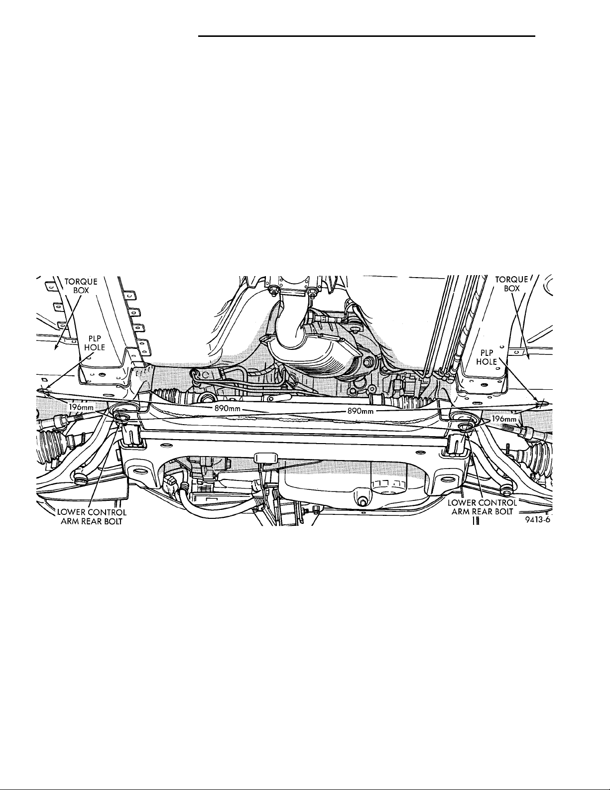
PLPHOLELOWER CONTROL ARMREAR BOLT
TORQUE BOX
LOWER CONTROL ARM REAR
PLP HOLE
TORQUE BOX
BOLT
13 - 4 FRAME AND BUMPERS PL
REMOVAL AND INSTALLATION (Continued)
(3) Place steering gear in position on crossmember.
(4) Install bolts to hold steering gear to crossmem-
ber.
(5) Position lifting device under the crossmember.
(6) Lift crossmember to frame rails.
(7) Engage bolts to hold crossmember rear mounts
into cage nuts in the frame torque boxes. Do not
tighten bolts.
(8) Install bolts to hold crossmember to frame rails
above lower control arms.
(9) Lower and remove lifting device.
(10) Align crossmember to index marks. Verify
that crossmember is at the specified dimensions from
the PLPs (Fig. 2).
(11) Tighten bolts to hold suspension crossmember
to frame rails and torque boxes.
(12) Insert ball joints into spindles.
(13) Install pinch bolts to hold front ball joints to
spindles.
(14) Install front wheels on vehicle.
(15) Lower vehicle and verify front suspension
alignment. If camber, caster settings and wheel stagger is not within specifications, loosen and reposition
crossmember to bring suspension within specifications. Refer to Group 2, Front Suspension and Driveshaft for additional information.
Fig. 2 Forward Frame and Suspension Crossmember
Page 5
PTMMPT MM
PL FRAME AND BUMPERS 13 - 5
SPECIFICATIONS
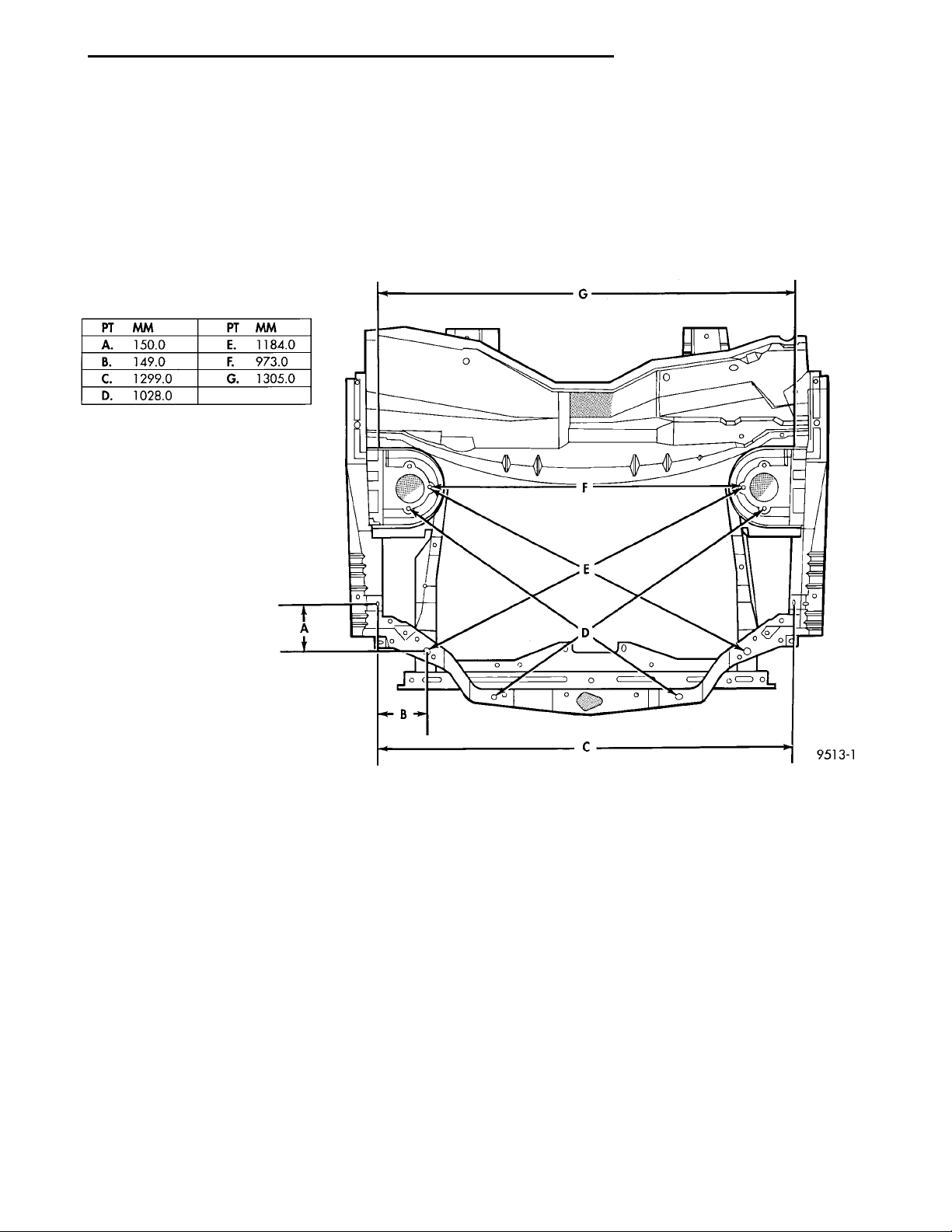
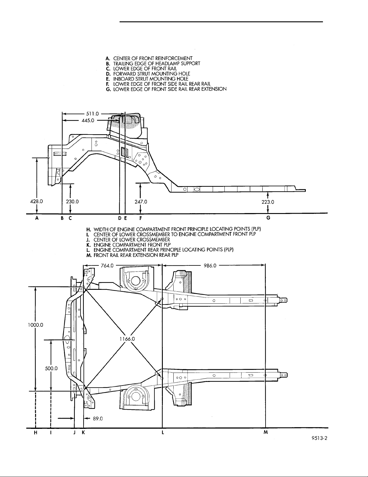
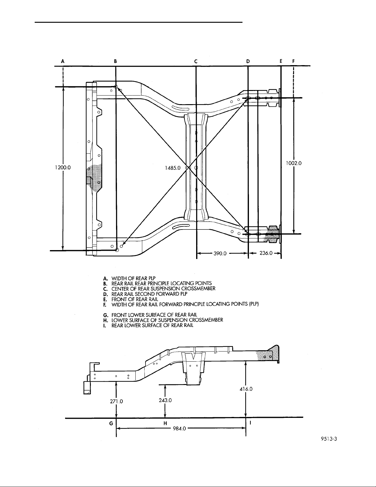
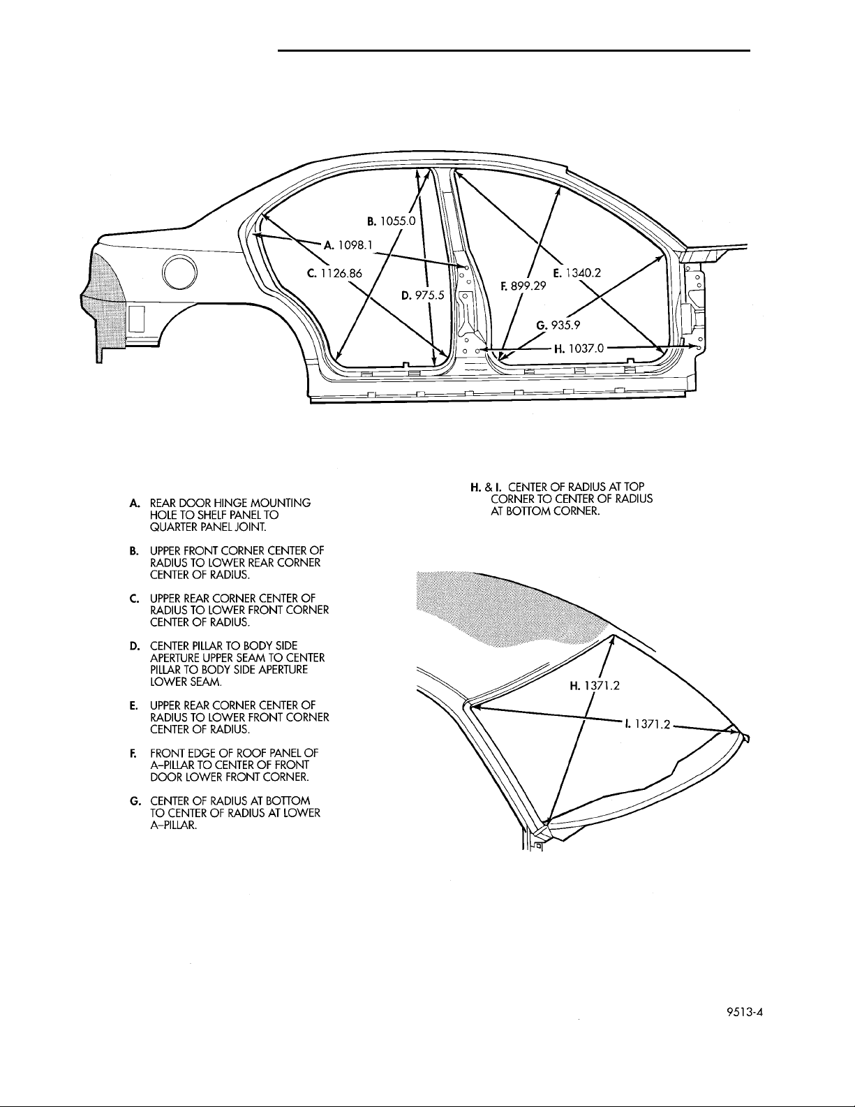
STRUCTURAL DIMENSIONS
Structural dimensions are listed in metric measurements. All dimensions are from center to center
of Principal Locating Point (PLP), or from center to
center of PLP and fastener location (Fig. 3), (Fig. 4),
(Fig. 5), (Fig. 6), (Fig. 7), and (Fig. 8).
Fig. 3 Engine Compartment Top View
Page 6
A. CENTER OF FRONT REINFORCEMENTB. TRAILING EDGE OF HEADLAMP SUPPORTC. LOWER EDGE OF FRONT RAILD. FORWARD STRUT MOUNTING HOLEE. INBOARD STRUT MOUNTING HOLEF. LOWER EDGE OF FRONT SIDE RAIL REAR RAILG. LOWER EDGE OF FRONT SIDE RAIL REAR EXTENSIONH. WIDTH OF ENGINE COMPARTMENT FRONT PRINCIPLE LOCATING POINTS(PLP)I. CENTER OF LOWER CROSSMEMBER TO ENGINE COMPARTMENT FRONT PLPJ. CENTER OF LOWER CROSSMEMBERK. ENGINE COMPARTMENT FRONT PLPL. ENGINE COMPARTMENT REAR PRINCIPLE LOCATING POINTS (PLP)M. FRONT RAIL REAR EXTENSION REAR PLP
13 - 6 FRAME AND BUMPERS PL
SPECIFICATIONS (Continued)
Fig. 4 Engine Compartment Side and Bottom View
Page 7
A. WIDTH OF REAR PLPB. REAR RAIL REAR PRINCIPLE LOCATING POINTSC. CENTER OF REAR SUSPENSION CROSSMEMBERD. REAR RAIL SECOND FORWARD PLPE. FRONT OF REAR RAILF. WIDTH OF REAR RAIL FORWARD PRINCIPLE LOCATING POINTS (PLP)G. FRONT LOWER SURFACE OF REAR RAILH. LOWER SURFACE OF SUSPENSION CROSSMEMBERI. REAR LOWER SURFACE OF REAR RAIL
PL FRAME AND BUMPERS 13 - 7
SPECIFICATIONS (Continued)
Fig. 5 Rear Frame Section Side and Bottom View
Page 8
A. REAR DOOR HINGE MOUNTING HOLE TO SHELFPANEL TO QUARTER PANEL JOINT.B. UPPER FRONT CORNER CENTER OF RADIUS TOLOWER REAR CORNER CENTER OF RADIUS.C. UPPER REAR CORNER CENTER OF RADIUS TOLOWER FRONT CORNER CENTER OF RADIUS.D. CENTER PILLAR TO BODY SIDE APERTURE UPPERSEAM TO CENTER PILLAR TO BODY SIDE APERTURELOWER SEAM.E. UPPER REAR CORNER CENTER OF RADIUS TOLOWER FRONT CORNER CENTER OF RADIUS.F. FRONT EDGE OF ROOF PANEL OF A-PILLAR TO CEN-TER OF FRONT DOOR LOWER FRONT CORNER.G. CENTER OF RADIUS AT BOTTOM TO CENTER OFRADIUS AT LOWER A-PILLAR. H. & I. CENTER OF RADIUS AT TOP CORNER TO CEN-TER OF RADIUS AT BOTTOM CORNER.
13 - 8 FRAME AND BUMPERS PL
SPECIFICATIONS (Continued)
Fig. 6 Door and Windshield Openings—4 Door
Page 9
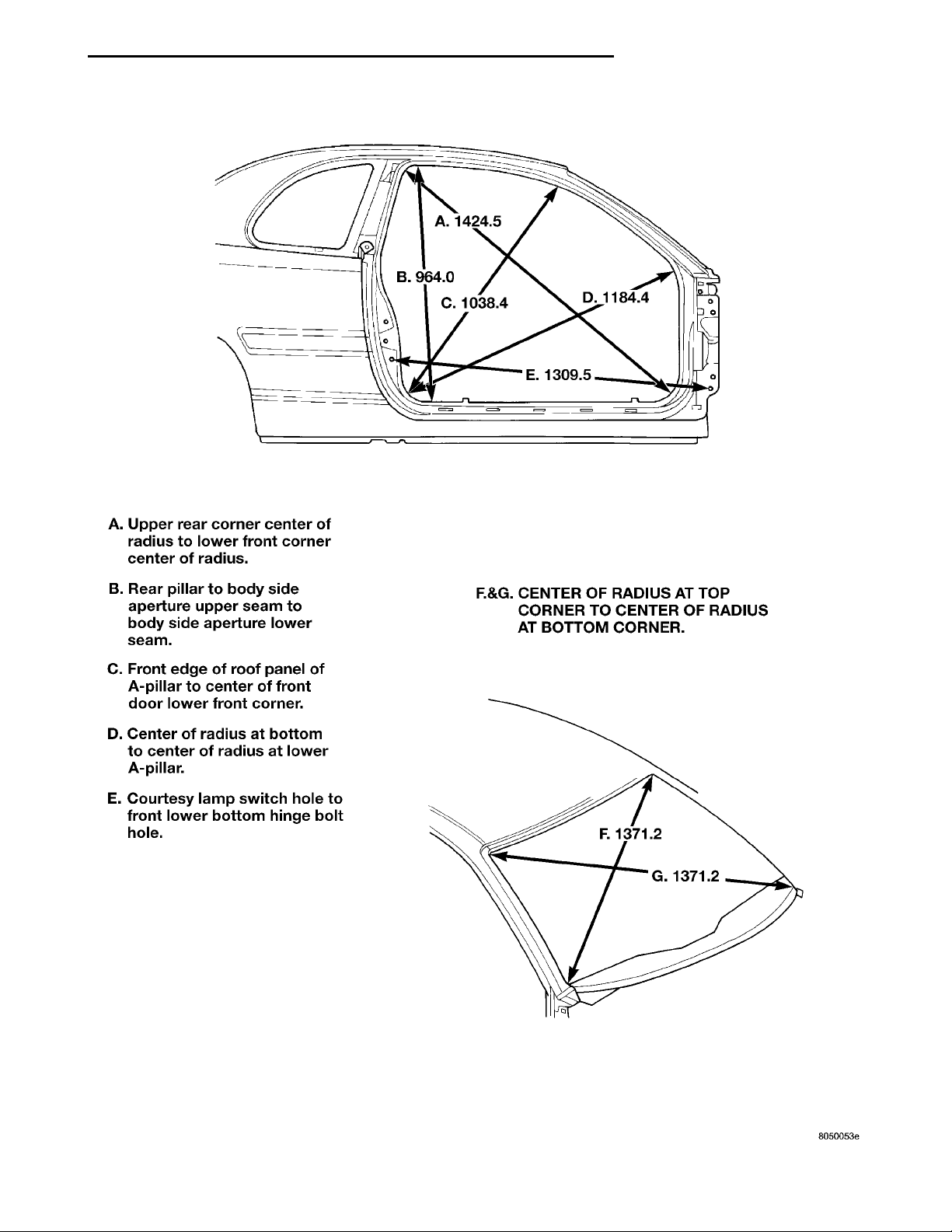
A. UPPER REAR CORNER CENTER OFRADIUS TO LOWER FRONT CORNERCENTER OF RADIUS.B. REAR PILLAR TO BODY SIDE APER-TURE UPPER SEAM TO BODY SIDEAPERTURE LOWER SEAM.C. FRONT EDGE OF ROOF PANEL OFA-PILLAR TO CENTER OF FRONTDOOR LOWER FRONT CORNER.D. CENTER OF RADIUS AT BOTTOM TOCENTER OF RADIUS AT LOWER A-PIL-LAR.E. COURTESY LAMP SWITCH HOLE TOFRONT LOWER BOTTOM HINGE BOLTHOLE. F. & G. CENTER OF RADIUS AT TOPCORNER TO CENTER OF RADIUS ATBOTTOM CORNER.
PL FRAME AND BUMPERS 13 - 9
SPECIFICATIONS (Continued)
Fig. 7 Door and Windshield Openings—2 Door
Page 10
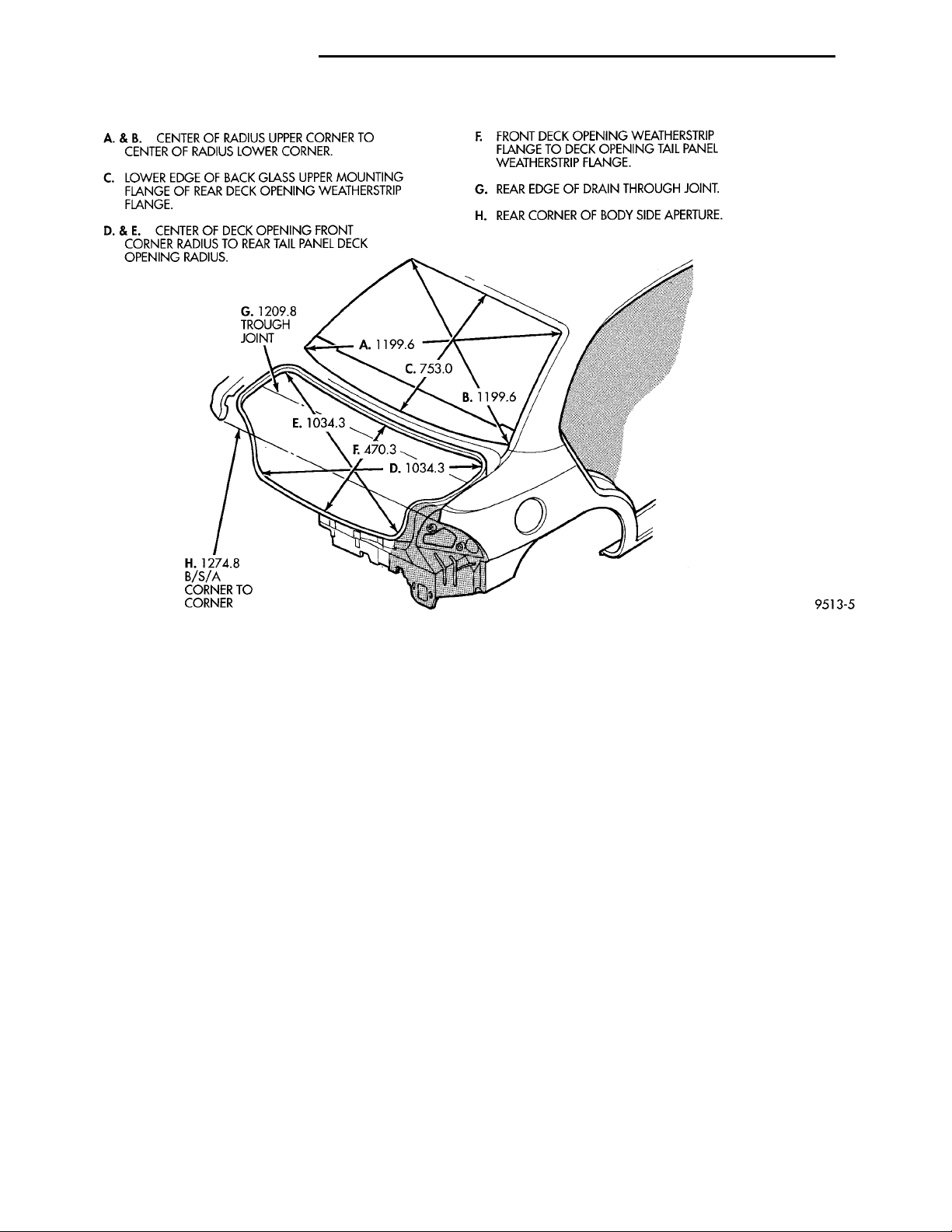
A. & B. CENTER OF RADIUS UPPERCORNER TO CENTER OF RADIUSLOWER CORNER.C. LOWER EDGE OF BACK GLASSUPPER MOUNTING FLANGE OF REARDECK OPENING WEATHERSTRIPFLANGE.D. & E. CENTER OF DECK OPENINGFRONT CORNER RADIUS TO REARTAIL PANEL DECK OPENING RADIUS. F. FRONT DECK OPENING WEATHER-STRIP FLANGE TO DECK OPENINGTAIL PANEL WEATHERSTRIP FLANGE.G. REAR EDGE OF DRAIN THROUGHJOINT.H. REAR CORNER OF BODY SIDEAPERTURE.THROUGH JOINTB/S/A CORNER TO CORNER
13 - 10 FRAME AND BUMPERS PL
SPECIFICATIONS (Continued)
Fig. 8 Rear Window and Trunk Openings
TORQUE SPECIFICATIONS
DESCRIPTION TORQUE
Front Bumper Reinforcement Nut. . 156 N·m (115 ft.
lbs)
RearBumperReinforcement Nut . 156 N·m (115ft. lbs)
FrontCrossmember ToBodyMountingBolts.163 N·m
(120 ft. lbs)
 Loading...